EP3526388B1 - Washing machine - Google Patents
Washing machine Download PDFInfo
- Publication number
- EP3526388B1 EP3526388B1 EP17873763.1A EP17873763A EP3526388B1 EP 3526388 B1 EP3526388 B1 EP 3526388B1 EP 17873763 A EP17873763 A EP 17873763A EP 3526388 B1 EP3526388 B1 EP 3526388B1
- Authority
- EP
- European Patent Office
- Prior art keywords
- tub
- air
- washing machine
- drum
- air inlet
- Prior art date
- Legal status (The legal status is an assumption and is not a legal conclusion. Google has not performed a legal analysis and makes no representation as to the accuracy of the status listed.)
- Active
Links
- 238000005406 washing Methods 0.000 title claims description 82
- XLYOFNOQVPJJNP-UHFFFAOYSA-N water Substances O XLYOFNOQVPJJNP-UHFFFAOYSA-N 0.000 claims description 33
- 230000007423 decrease Effects 0.000 claims description 4
- 238000001035 drying Methods 0.000 description 24
- 230000000052 comparative effect Effects 0.000 description 6
- 238000006073 displacement reaction Methods 0.000 description 4
- 239000011347 resin Substances 0.000 description 4
- 229920005989 resin Polymers 0.000 description 4
- 238000004891 communication Methods 0.000 description 3
- 238000000034 method Methods 0.000 description 3
- 238000012856 packing Methods 0.000 description 3
- 230000000149 penetrating effect Effects 0.000 description 3
- 230000001419 dependent effect Effects 0.000 description 2
- 230000000694 effects Effects 0.000 description 2
- 238000002347 injection Methods 0.000 description 2
- 239000007924 injection Substances 0.000 description 2
- 238000012986 modification Methods 0.000 description 2
- 230000004048 modification Effects 0.000 description 2
- 230000002093 peripheral effect Effects 0.000 description 2
- 238000010992 reflux Methods 0.000 description 2
- 239000000725 suspension Substances 0.000 description 2
- 239000000956 alloy Substances 0.000 description 1
- 229910045601 alloy Inorganic materials 0.000 description 1
- XAGFODPZIPBFFR-UHFFFAOYSA-N aluminium Chemical compound [Al] XAGFODPZIPBFFR-UHFFFAOYSA-N 0.000 description 1
- 229910052782 aluminium Inorganic materials 0.000 description 1
- 230000015572 biosynthetic process Effects 0.000 description 1
- 230000007812 deficiency Effects 0.000 description 1
- 238000009434 installation Methods 0.000 description 1
- 239000000463 material Substances 0.000 description 1
- 239000011148 porous material Substances 0.000 description 1
- 230000003014 reinforcing effect Effects 0.000 description 1
- 230000000717 retained effect Effects 0.000 description 1
- 239000000243 solution Substances 0.000 description 1
- 238000003756 stirring Methods 0.000 description 1
- 238000011144 upstream manufacturing Methods 0.000 description 1
Images


Classifications
-
- D—TEXTILES; PAPER
- D06—TREATMENT OF TEXTILES OR THE LIKE; LAUNDERING; FLEXIBLE MATERIALS NOT OTHERWISE PROVIDED FOR
- D06F—LAUNDERING, DRYING, IRONING, PRESSING OR FOLDING TEXTILE ARTICLES
- D06F37/00—Details specific to washing machines covered by groups D06F21/00 - D06F25/00
- D06F37/20—Mountings, e.g. resilient mountings, for the rotary receptacle, motor, tub or casing; Preventing or damping vibrations
- D06F37/22—Mountings, e.g. resilient mountings, for the rotary receptacle, motor, tub or casing; Preventing or damping vibrations in machines with a receptacle rotating or oscillating about a horizontal axis
- D06F37/225—Damping vibrations by displacing, supplying or ejecting a material, e.g. liquid, into or from counterbalancing pockets
-
- D—TEXTILES; PAPER
- D06—TREATMENT OF TEXTILES OR THE LIKE; LAUNDERING; FLEXIBLE MATERIALS NOT OTHERWISE PROVIDED FOR
- D06F—LAUNDERING, DRYING, IRONING, PRESSING OR FOLDING TEXTILE ARTICLES
- D06F35/00—Washing machines, apparatus, or methods not otherwise provided for
- D06F35/005—Methods for washing, rinsing or spin-drying
- D06F35/007—Methods for washing, rinsing or spin-drying for spin-drying only
-
- D—TEXTILES; PAPER
- D06—TREATMENT OF TEXTILES OR THE LIKE; LAUNDERING; FLEXIBLE MATERIALS NOT OTHERWISE PROVIDED FOR
- D06F—LAUNDERING, DRYING, IRONING, PRESSING OR FOLDING TEXTILE ARTICLES
- D06F23/00—Washing machines with receptacles, e.g. perforated, having a rotary movement, e.g. oscillatory movement, the receptacle serving both for washing and for centrifugally separating water from the laundry
- D06F23/02—Washing machines with receptacles, e.g. perforated, having a rotary movement, e.g. oscillatory movement, the receptacle serving both for washing and for centrifugally separating water from the laundry and rotating or oscillating about a horizontal axis
-
- D—TEXTILES; PAPER
- D06—TREATMENT OF TEXTILES OR THE LIKE; LAUNDERING; FLEXIBLE MATERIALS NOT OTHERWISE PROVIDED FOR
- D06F—LAUNDERING, DRYING, IRONING, PRESSING OR FOLDING TEXTILE ARTICLES
- D06F37/00—Details specific to washing machines covered by groups D06F21/00 - D06F25/00
- D06F37/02—Rotary receptacles, e.g. drums
-
- D—TEXTILES; PAPER
- D06—TREATMENT OF TEXTILES OR THE LIKE; LAUNDERING; FLEXIBLE MATERIALS NOT OTHERWISE PROVIDED FOR
- D06F—LAUNDERING, DRYING, IRONING, PRESSING OR FOLDING TEXTILE ARTICLES
- D06F37/00—Details specific to washing machines covered by groups D06F21/00 - D06F25/00
- D06F37/26—Casings; Tubs
- D06F37/267—Tubs specially adapted for mounting thereto components or devices not provided for in preceding subgroups
-
- D—TEXTILES; PAPER
- D06—TREATMENT OF TEXTILES OR THE LIKE; LAUNDERING; FLEXIBLE MATERIALS NOT OTHERWISE PROVIDED FOR
- D06F—LAUNDERING, DRYING, IRONING, PRESSING OR FOLDING TEXTILE ARTICLES
- D06F2103/00—Parameters monitored or detected for the control of domestic laundry washing machines, washer-dryers or laundry dryers
- D06F2103/28—Air properties
- D06F2103/36—Flow or velocity
-
- D—TEXTILES; PAPER
- D06—TREATMENT OF TEXTILES OR THE LIKE; LAUNDERING; FLEXIBLE MATERIALS NOT OTHERWISE PROVIDED FOR
- D06F—LAUNDERING, DRYING, IRONING, PRESSING OR FOLDING TEXTILE ARTICLES
- D06F2105/00—Systems or parameters controlled or affected by the control systems of washing machines, washer-dryers or laundry dryers
- D06F2105/16—Air properties
- D06F2105/24—Flow or velocity
-
- D—TEXTILES; PAPER
- D06—TREATMENT OF TEXTILES OR THE LIKE; LAUNDERING; FLEXIBLE MATERIALS NOT OTHERWISE PROVIDED FOR
- D06F—LAUNDERING, DRYING, IRONING, PRESSING OR FOLDING TEXTILE ARTICLES
- D06F25/00—Washing machines with receptacles, e.g. perforated, having a rotary movement, e.g. oscillatory movement, the receptacle serving both for washing and for centrifugally separating water from the laundry and having further drying means, e.g. using hot air
Definitions
- Embodiments of the present disclosure relate to a washing machine performing a series of processes of washing, rinsing, and spin-drying by rotating a drum containing clothes with respect to a horizontal axis.
- a drum type washing machine is provided with a laundry loading/unloading opening 101 that is closed by a door at the front of an outer case 100 and laundry such as clothes is introduced there into through the laundry loading/unloading opening 101.
- a cylindrical tub 102 with a bottom is placed horizontally in the outer case 100.
- a cylindrical drum 103 having a bottom and a circumferential wall provided with a plurality of through-holes is rotatably disposed in the tub 102.
- a series of processes of washing, rinsing, and spin-drying are automatically performed in a state where clothes are contained in the drum 103.
- the tub 102 may be disposed such that an opening is positioned adjacent to the laundry loading/unloading opening 101 to face the laundry loading/unloading opening 101.
- the tub 102 may be elastically supported by the outer case 100 by using a suspension or the like.
- a gap between the opening of the tub 102 and the laundry loading/unloading opening 101 may be sealed by an elastic packing material or the like to prevent water leakage.
- the tub 102 becomes in an approximately sealed state by closing the door of the laundry loading/unloading opening 101 when it is in use. However, it is not an airtight state but a so-called watertight state. That is, even in washing, rinsing, and spin-drying cycles, the inside of the tub 102 generally communicates with the outside via a water supply path or a drain path disposed at radially outward portions of the tub 102. Thus, air may flow out of the tub 102.
- the drum 103 rotates about a rotational axis J at a high speed to remove moisture from laundry during spin-drying.
- air contained in the drum 103 is also forced to flow in a radially outward direction as indicated by arrows A of FIG. 1 .
- air flowing out of the drum is returned into the drum 103 from areas surroundings of an opening of the drum 103 as indicated by arrows B if there is a sufficient gap between an outer circumferential surface of the drum 103 and an inner circumferential surface of the tub 102.
- a bottom surface of the drum 103 has holes, air, even in a small amount, may be returned into the drum 103 through the holes of the bottom surface of the drum 103 as indicated by an arrow B' of FIG. 1 .
- a part of air forced to flow out of the drum 103 flows out of the tub 102 through a water supply path or a drain path so that an amount of air contained in the tub 102 decreases.
- the capacity of the drum 103 has increased and thus a gap between the outer circumferential surface of the drum 103 and the inner circumferential surface of the tub 102 has narrowed.
- reflux of air into the drum 103 is inhibited and air easily flows out of the tub 102 through the water supply path or drain path.
- the tub 102 moves forward and brought into contact with surrounding members making noise and causing discomfort to a user.
- EP0795639 discloses a drum washer with a washing tub supported by suspension means in a housing.
- EP1314809 discloses a drum-type washing/drying machine having a large outer tub and a housing with an opening formed on the top.
- a drying air channel including a heater is disposed on an outer side of the tub.
- the air inflow channel may include an air inlet formed at a rear surface of the door.
- the air inlet may be formed at an upper portion than a rotational axis of the drum.
- a rib radially extending from the center of the end wall may be provided on the outer surface of the end wall, and the rib may constitute one surface of the air inflow channel.
- the cover member may further include a rib fitting part fitted to the rib.
- the tub may further include a cylindrical main body wall, an air outlet to discharge air is formed at one portion of the main body wall, and the air inflow channel may connect the air outlet with the air inlet.
- the washing machine may further include an auxiliary cover member mounted on an outer surface of the main body wall and configured to guide air from the air outlet to an upper portion of the cover member.
- an exemplary a washing machine may include a case comprising a laundry loading/unloading opening through which laundry is introduced, a door mounted at the case to open or close the laundry loading/unloading opening, a tub disposed inside the case and having an opening connected to the laundry loading/unloading opening, a drum rotatably disposed inside the tub, and an air inlet disposed at one surface of the tub or one surface of the door to allow air to flow to a central portion of the drum while the drum rotates.
- the tub may include an end wall facing the opening, and the air inlet may be formed at one portion of the end wall.
- the washing machine may further include a cover member mounted on one surface of the end wall and connected to the air inlet to constitute an air inflow channel configured to guide air.
- the air inflow channel may include an inlet through which air is introduced and an outlet through which air is discharged, and the inlet may be disposed at an upper portion than the outlet to prevent water contained in the tub from flowing out of the tub through the air inflow channel.
- the tub may include a cylindrical main body wall, and an air outlet formed at one portion of the main body wall to discharge air contained in the drum while the drum rotates.
- the washing machine further may include an auxiliary cover member mounted on an outer surface of the main body wall and configured to guide air from the air outlet to an upper portion of the cover member.
- a washing machine includes a case comprising a laundry loading/unloading opening through which laundry is introduced, a tub disposed inside the case and comprising an end wall facing the laundry loading/unloading opening and a cylindrical main body wall, a drum rotatably disposed inside the tub, and an air inflow channel configured to guide air toward a central portion of the drum while the drum rotates.
- the air inflow channel may be formed by designing a gap between at least one of a front end portion and a rear end portion of the circumferential wall and the main body wall to be greater than a gap between a middle portion of the circumferential wall and the main body wall.
- the air inflow channel may be formed by disposing a baffle plate extending between a rear end portion of the drum and the tub to face an inner surface of the tub with a gap therebetween.
- noise generated during spin-drying may be suppressed, thereby improving comport.
- FIGS. 1 through 13 discussed below, and the various embodiments used to describe the principles of the present disclosure in this patent document are by way of illustration only and should not be construed in any way to limit the scope of the disclosure. Those skilled in the art will understand that the principles of the present disclosure may be implemented in any suitably arranged system or device.
- FIGS. 2 and 3 illustrate a washing machine 1 according to an embodiment of the present disclosure.
- the washing machine 1 may be a fully automatic washing machine that automatically performs a series of processes of washing, rinsing, and spin-drying.
- the washing machine 1 is not provided with a function of a dryer, the present disclosure may also be applied to a combo washer dryer in which washing machine and clothes dryer are merged into a single device.
- the washing machine 1 may include an outer case 10, a tub 20, a drum 30, and a motor 40.
- the outer case 10 may be provided in a rectangular parallelepiped shape formed by assembling a front panel 11, a rear panel 12, a pair of side panels 13, a top panel 14, and a bottom panel 15.
- the front panel 11 is provided with a circular laundry loading/unloading opening 17 that is opened or closed by a door 18 mounted with an annular diaphragm 16.
- a control unit 19 such as a switch or a monitor allowing a user to drive the washing machine 1 may be disposed at an upper portion than the laundry loading/unloading opening 17.
- the tub 20 is formed of a cylindrical container with a bottom made of an injection molded member of a resin and includes a circular opening portion 21 having an opening 21a with the substantially same diameter as the laundry loading/unloading opening 17, a disk-shaped end wall 22 facing the opening portion 21, and a cylindrical main body wall 23 interposed therebetween.
- a bearing housing 23 having a shaft hole 23a and formed of an alloy of aluminum or the like is integrated with a resin at the central region of the end wall 22.
- the outer surface of the end wall 22 is provided with a plurality of diametric ribs 25 that radially extends from the central region and a plurality of circumferential ribs 26 that are arranged to as concentric circles around the central region to reduce weight of the tub 20 and increase rigidity thereof.
- the outer surface of the end wall 22 is also provided with a cover member 50 which will be described later.
- the tub 20 is horizontally located in the outer case 10 such that the opening portion 21 faces forward and the opening 21a and the laundry loading/unloading opening 17 are located to horizontally overlap each other.
- a pair of springs 2 is installed at front and rear upper portions inside the outer case 10 to be spaced apart from each other in the horizontal direction and a pair of dampers 3 is installed at left and right lower portions inside the outer case 10 to be spaced apart from each other in the horizontal direction.
- the tub 20 is elastically supported by the outer case 10 via the springs 2 and dampers 3.
- the opening portion 21 is connected to the diaphragm 16 and a gap between the laundry loading/unloading opening 17 and the opening 21a is sealed by the diaphragm 16. Thus, the opening 21a is sealed by closing the door 18.
- a water receiving container 5 that receives water supplied from the outside around an upper part of the tub 20.
- the water receiving container 5 is connected to a water supply port 27 installed at an upper portion of the tub 20 through a water supply hose 6 and a predetermined amount of water is supplied into the tub 20 via the water receiving container 5 and the water supply port 27 during the washing or rinsing cycle.
- Air contained in the tub 20 may be discharged out of the tub 20 via the water supply hose 6 and the water receiving container 5.
- a drain port 28 is installed at a lower portion of the tub 20.
- a drain hose 7 is connected to the drain port 28.
- One end portion of the drain hose 7 is exposed to the outside of the outer case 10.
- a circulation pump may be provided at an upstream side of the drain hose 7 to circulate water stored in the tub 20 during the washing or rinsing cycle.
- the inside of the tub 20 communicates with the outside of the tub 20 through the drain hose 7 so that air inside the tub 20 may flow out.
- the drum 30 is a cylindrical container slightly smaller than the tub 20 and includes a circular front portion 31 having a drum opening 31a with a slightly smaller diameter than the opening 21a, a flange shaft 32 facing the front portion 31, and a cylindrical circumferential wall 33 connecting the front portion 31 with the flange shaft 32.
- An outer circumferential surface of the circumferential wall 33 faces an inner circumferential surface of the main body wall 24 with a slight gap (micro-gap) therebetween.
- the circumferential wall 33 has a plurality of through-holes 33a (a group of pores) penetrating the circumferential wall 33 ( FIG. 2 illustrates a part thereof) and formed over the entire surface thereof.
- the flange shaft 32 includes a boss portion 32a to which one end of the shaft 34 is fixed, an arm portion 32b radially extending from the boss portion 32a, and a circular flange portion 32c leading to a tip end of each arm portion 32b and fixed to the circumferential wall 33.
- the front surface of the flange shaft 32 is covered with a disk-shaped cover 32d having a plurality of holes 32e.
- the cover 32d constitutes the bottom surface of the drum 30.
- the shaft 34 is supported in the shaft hole 23a of the bearing housing 23 by the bearing 35 and the drum 30 rotates about a substantially horizontal rotational axis J in the tub 20.
- the motor 40 is mounted under the tub 20 such that a drive shaft 41 thereof protrudes backward parallel to the rotational axis J.
- a sub pulley 42 having a smaller diameter is fixed to a tip end of the drive shaft 41.
- a main pulley 43 having a larger diameter is fixed to one end of the shaft 34 protruding out from the tub 20 through the shaft hole 23a.
- An endless belt 44 is installed at the sub pulley 42 and the main pulley 43.
- Driving of the motor 40 is controlled by a control device (not shown) that controls the overall operation of the washing machine 1.
- rotational direction or rotational speed of the driver shaft 41 vary at a predetermined timing.
- the drum 30 rotates at a low speed, e.g., 30 rpm, at which clothes are not in contact with the circumferential wall 33 in a state where wash water or rinse water is retained in the tub 20, and clothes are agitated with wash water.
- the drum 30 rotates at a speed at which clothes are forced to be in contact with the circumferential wall 33 to perform a spin-drying process. That is, the inside of the tub 20 communicates the outside thereof through the water supply hose 6 or the drain hose 7 and the drum 30 rotates at a high speed of 1000 rpm or higher for a predetermined time period in a state where air passes therethrough. Thus, water contained in the clothes flows out of the drum 30 through the through-holes 33a, contained in the tub 20, and drains via the drain hose 7.
- an air inflow structure that supplies air into the central portion of the drum 30 may be disposed between the drum 30 and the tub 20 in the washing machine 1 such that a pressure difference is not caused in the tub 20.
- an air inlet communicating with the outside of the tub 20 is formed at the central region of the end wall 22 facing the inside of the tub 20.
- the air inlet is located at the central portion of the tub 20, and thus air may flow into the central portion of the tub 20 without being disturbed by an airflow formed inside the drum 30 in a radially outward direction. Therefore, a pressure difference is not caused in the tub 20.
- an air inlet 60 penetrating the wall is formed at a central region of the end wall 22, particularly, around an upper portion of the bearing housing 23.
- the air inlet 60 is disposed in the vicinity of the upper portion of the bearing housing 23 since a resin is easily molded and it is difficult for water or bubbles to flow out of the tub 20 through the air inlet 60 during the washing or rinsing cycle among central regions.
- an air inflow path is formed in the washing machine 1 by mounting a cover member 50 on the outer surface of the end wall 22 to prevent water or bubbles from flowing into the outer case 10 even after water or bubbles flow out of the air inlet 60.
- the cover member 50 is illustrated in FIGS. 6 and 7 .
- the cover member 50 may be formed of an injection molded product of a plate type resin and may include a cover body 51 having a shape corresponding to a structure of the outer surface of the end wall 22 and fastening flanges 52 protruding from a plurality of portions of an outer circumference of the cover body 51.
- the cover body 51 has a plate-shaped first plate part 51a and a second plate part 51b that forms a channel having a small thickness at a portion of the first plate part 51a.
- the second plate part 51b has an external air inlet 53 having a large width at one end thereof and communicates a middle opening 54 formed at the center of the first plate part 51a with an external air input 53.
- the first plate part 51a has a rib fitting part 55 to engage the diametric rib 25 with the circumferential rib 26.
- the rib fitting part 55 is formed in a rim shape along the outer periphery of a predetermined region of the first plate part 51a including the middle opening 54.
- the rib fitting part 55 may be provided with an elastic packing 56.
- a path forming structure constituting an air inflow path may be formed using the diametric rib 25 and the circumferential rib 26 at a portion of the end wall 22 mounted with the cover body 51.
- fastening bosses 61 are provided at a plurality of locations of the outer surface of the end wall 22 to correspond to the arrangement of the fastening flanges 52.
- a first circumferential rib 26a, a second circumferential rib 26b, a third circumferential rib 26c, and a fourth circumferential rib 26d are sequentially disposed on the outer surface of the end wall 22 from the center thereof at predetermined intervals.
- the first circumferential rib 26a and the third circumferential rib 26c are sub ribs which are thinner than the second circumferential rib 26b and the fourth circumferential rib 26d which are main ribs.
- the main ribs and the sub ribs are alternately arranged in the radial direction.
- the diametric ribs 25 include thicker main ribs and thinner sub ribs which are alternately arranged in the circumferential direction. While main diametric ribs 25a of the diametric ribs 25 extend from the central portion to the outer circumferential side, sub diametric ribs 25b of the diametric ribs 25 extend from the outer circumference of the first circumferential rib 26a. Protruding ends of the diametric ribs 25 and protruding ends of the circumferential ribs 26 are connected with each other and located at the substantially same height.
- the air inlet 60 is formed to have a large area using a relatively large space between two adjacent main diametric ribs 25a which are disposed closer to the center than the first circumferential rib 26a.
- a communication path 62 is formed in the radial direction by removing a half of one portion of the first circumferential rib 26a defined by adjacent sub diametric ribs 25b.
- a reinforcing rib 63 is installed between adjacent main diametric ribs 25a disposed at both sides of the air inlet 60 at the center of the air inlet 60 in order to prevent a decrease in rigidity of the end wall 22 caused by formation of the communication path 62 and the air inlet 60.
- a portion of the second circumferential rib 26b (main rib) between the main diametric rib 25a and the sub diametric rib 25b adjacent to the communication path 62 may be formed to have a relatively low height, e.g., about half as high as the other portions (lower rib 64).
- the cover member 50 is mounted on the end wall 22 to cover a predetermined portion of the outer surface of the end wall 22 in a state where the external air inlet 53 faces upward by screw fixing each of the fastening flanges 52 overlapping each of the fastening bosses 61.
- the rib fitting part 55 is brought into close contact with a predetermined region (marked as oblique lines in FIG.
- the closed space 65 communicates with the second plate part 51b via the middle opening 54 by disposing the lower rib 64 below the middle opening 54.
- the air inflow path is formed upward from the central region of the outer surface of the end wall 22, and the air inlet 60 communicates with the outside of the tub 20 through the external air inlet 53 located at an upper portion of the tub 20.
- the cover member 50 Since side walls of the air inflow path are defined by the diametric rib 25 and the circumferential rib 26 installed at the outer surface of the end wall 22, the cover member 50 has a simple structure. In addition, since the side walls are coupled with the thin second plate part 51b, the air inflow path may have a large volume without protruding from the end wall 22. As indicated by arrows of FIG. 5 , air may be efficiently introduced into the center inside the tub 20. As the air inflow path protrudes farther from the end wall 22, the volume of the tub 20 should be reduced with respect to the outer case 10. However, there is no need to reduce the volume of the tub 20 in the washing machine 1, thereby increasing the volume of the tub 20.
- FIG. 8A is a graph illustrating the relationship between changes in revolutions per minute (rpm) of a drum and the degree of displacement (mm) of a tub moving forward during spin-drying of a washing machine as a comparative embodiment before the air inlet and the air inflow path are formed.
- FIG. 8B is a graph illustrating the relationship between changes in rpm of a drum and the degree of displacement (mm) of a tub moving forward during spin-drying of a washing machine having the abovementioned air inlet and air inflow path according to the present disclosure.
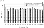
- FIG. 9 is a graph illustrating noise levels (PWL) during spin-drying of the washing machines according to the present embodiment and the comparative embodiment.
- the horizontal axis indicates frequency (Hz).
- the washing machine according to the present embodiment produces less noise than the washing machine according to the comparative embodiment. Therefore, it was confirmed that noise suppressing effect may be obtained during spin-drying according to the present embodiment.
- FIG. 10 illustrates a first modified embodiment of the washing machine 1 described above.
- a washing machine 1A according to the first modified embodiment has the same structure except for an air inflow structure in comparison with the aforementioned washing machine 1, and thus the same reference numerals are used and detailed descriptions thereof will not be repeated.
- an opening (external air introduction opening 70) penetrating the wall surface of the end wall 22 is formed at an upper end portion, not the central region, of the end wall 22.
- the external air introduction opening 70 is formed on the wall surface 22a of the end wall 22 defined by adjacent main diametric rib 25a, diametric rib 25b, third circumferential rib 26c, and fourth circumferential rib 26d.
- a bend-shaped guide member 71 having a door-shaped cross-section, a closed upper end, and an open lower end is mounted on the inner surface of the end wall 22.
- a channel (inner channel 72) extending downward from the upper end along the inner surface of the end wall 22 is formed.
- the upper end of the guide member 71 is disposed to cover the external air introduction opening 70, and the lower end of the guide member 71 is disposed at the central region of the end wall 22.
- an air inflow path is formed by the inner channel 72 communicating with the outside of the tub 20 via the external air introduction opening 70 and an air inlet is formed at a lower end 72a of the inner channel 72 communicating with the inside of the tub 20.
- the structure of the outer surface of the end wall 22 may be the same as those of conventional washing machines.
- installation of the tub 20 with regard to the outer case 10 is not limited. Since the external air introduction opening 70 is formed at an outer peripheral portion of the end wall 22, rigidity of the tub 20 may be improved.
- FIG. 11 illustrates a second modified embodiment of the washing machine 1 described above.
- a washing machine 1B according to the second modified embodiment has the same structure except for an air inflow structure in comparison with the aforementioned washing machine 1 or the washing machine A, and thus the same reference numerals are used and detailed descriptions thereof will not be repeated.
- An air inflow structure of the washing machine 1B includes an airing path 80 formed by designing a gap between a rear end portion of the circumferential wall 33 and the main body wall 24 to be greater than a gap between a middle portion of the circumferential wall 33 (between the front end portion and the rear end portion of the circumferential wall 33) and the main body wall 24. That is, the gap between the circumferential wall 33 and the main body wall 24 is very small as a result of increasing the capacity of the drum 30. Thus, air does not easily flow through the gap and reflux of air is inhibited, so that a large amount of air is discharged out of the tub 20 through the water supply hose 6 or the drain hose 7 causing a pressure difference in the tub 20.
- the airing path 80 is formed by increasing an inner diameter of the upper corner to be greater than the other portions in the rear end portion of the tub 20 to enlarge the gap therebetween. Since the rear end portion of the circumferential wall 33 faces the airing path 80, the rear end portion of the circumferential wall 33 communicates with a gap (rear gap) between the end wall 22 of the tub 20 and the flange shaft 32 of the drum 30. Thus, a part of air flowing out of from the circumferential wall 33 of the drum 30 may be returned to the central portion of the drum 30 via the airing path 80 and the rear gap. That is, in this washing machine 1B, the airing path 80 and the rear gap constitute the air inflow structure.
- the airing path 80 may be formed by making an outer diameter of the rear end portion of the drum 30 to be relatively small.
- FIG. 12 illustrates a third modified embodiment of the washing machine 1 described above.
- a washing machine 1C according to the third modified embodiment has the same structure except for an air inflow structure in comparison with the aforementioned washing machine 1 or the like, and thus the same reference numerals are used and detailed descriptions thereof will not be repeated.
- an air outlet 90 facing the circumferential wall 33 of the drum 30 is formed on a rear end portion of the main body wall 24 of the tub 20.
- the tub 20 is provided with an auxiliary cover member 91 and the auxiliary cover member constitutes a bypass communicating with the external air inlet 53.
- the air outlet 90 is covered by the auxiliary cover member 91.
- FIG. 13 illustrates a fourth embodiment of the washing machine 1 described above.
- a washing machine ID according to the fourth modified embodiment has the same structure except for an air inflow structure in comparison with the aforementioned washing machine 1 or the like, and thus the same reference numerals are used and detailed descriptions thereof will not be repeated.
- An air inflow structure of the washing machine ID includes a baffle plate 80 disposed between the rear end portion of the drum 30 and the tub 20.
- the baffle plate 80 is disposed to expand in a gap between the inner surface of the tub 20 from a rear upper portion of the main body wall 24 to at least the central region of the end wall 22 and the outer surface of the rear end portion (particularly, the rear end portion of the circumferential wall 3 and the flange shaft 32) of the drum 30 and to face the inner surface of the tub 20 at an interval.
- the baffle plate 80 is formed of a thin plate member and includes a main wall 80a expanding from the central portion of the end wall 22 to the upper end portion thereof along the inner surface of the wall surface 22a and a sub wall 80b connected to the main wall 80a and expanding forward along the inner surface of the main body wall 24.
- An air path that induces an airflow from a front end portion of the sub wall 80b to the center of the main wall 80a is formed by the gap between the baffle plate 80 and the inner surface of the tub 20.
- a wall mount type or pillar type support member (not shown) is provided on the inner surface of the tub 20 facing the baffle plate 80 not to block the airflow and the baffle plate 80 is supported by the support member.
- air flowing out from the rear end portion of the drum 30 in the circumferential direction collides with the inner surface of the tub 20 and flows out of the tub 20 or is diffused forming turbulence if there is no sub wall 80b.
- the air collides with the side wall 80b and the baffle path is not influenced thereby, and thus air may be smoothly introduced into the baffle path.
- An airflow in the radially outward direction from the central portion of the drum 30 is formed in the gap between the flange shaft 32 of the drum 30 and the inner surface of the wall surface 22a of the end wall 22 as shown by dashed lines of FIG. 13 when the drum 30 rotates at a high speed.
- a strong airflow may easily be generated by stirring the arm portions 32b.
- the gap may be partitioned into one side of the flange shaft 32 and the other side of the end wall 22 by installing the baffle plate 80 and influence of a reverse airflow is not applied to the baffle path.
- air may be smoothly introduced toward the central portion of the drum 30.
- air flowing out of the drum 30 in the radially outward direction during spin-drying may be smoothly returned to the central portion of the drum 30 via the baffle path, and thus a pressure difference is not caused, thereby suppressing the noise.
- the drum type washing machine is not limited to the aforementioned embodiments and may also include various other configurations.
- the air inlet is formed at the central region of the end wall 22 of the tub 20 in the washing machine 1 according to the present embodiment, an air inlet may also be formed at the center of the door 18 by mounting the guide member 71 described above with reference to the modified embodiments on the inner surface of the door 18 or the like.
- the air inflow structure of each modified embodiment may also be installed at a front portion of the drum 30 or at both front and rear portions thereof.
Landscapes
- Engineering & Computer Science (AREA)
- Textile Engineering (AREA)
- Main Body Construction Of Washing Machines And Laundry Dryers (AREA)
Description
- Embodiments of the present disclosure relate to a washing machine performing a series of processes of washing, rinsing, and spin-drying by rotating a drum containing clothes with respect to a horizontal axis.
- In general, as illustrated in
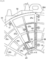
FIG. 1 , a drum type washing machine is provided with a laundry loading/unloadingopening 101 that is closed by a door at the front of anouter case 100 and laundry such as clothes is introduced there into through the laundry loading/unloadingopening 101. Acylindrical tub 102 with a bottom is placed horizontally in theouter case 100. Acylindrical drum 103 having a bottom and a circumferential wall provided with a plurality of through-holes is rotatably disposed in thetub 102. A series of processes of washing, rinsing, and spin-drying are automatically performed in a state where clothes are contained in thedrum 103. - The
tub 102 may be disposed such that an opening is positioned adjacent to the laundry loading/unloadingopening 101 to face the laundry loading/unloadingopening 101. Thetub 102 may be elastically supported by theouter case 100 by using a suspension or the like. A gap between the opening of thetub 102 and the laundry loading/unloading opening 101 may be sealed by an elastic packing material or the like to prevent water leakage. - The
tub 102 becomes in an approximately sealed state by closing the door of the laundry loading/unloading opening 101 when it is in use. However, it is not an airtight state but a so-called watertight state. That is, even in washing, rinsing, and spin-drying cycles, the inside of thetub 102 generally communicates with the outside via a water supply path or a drain path disposed at radially outward portions of thetub 102. Thus, air may flow out of thetub 102. - The
drum 103 rotates about a rotational axis J at a high speed to remove moisture from laundry during spin-drying. In this case, air contained in thedrum 103 is also forced to flow in a radially outward direction as indicated by arrows A ofFIG. 1 . In this case, air flowing out of the drum is returned into thedrum 103 from areas surroundings of an opening of thedrum 103 as indicated by arrows B if there is a sufficient gap between an outer circumferential surface of thedrum 103 and an inner circumferential surface of thetub 102. Also, since a bottom surface of thedrum 103 has holes, air, even in a small amount, may be returned into thedrum 103 through the holes of the bottom surface of thedrum 103 as indicated by an arrow B' ofFIG. 1 . - However, an airflow is formed in a radially outward direction in the
drum 103. Thus, the returned air is immediately drawn into the airflow when it enters thedrum 103. As a result, it is difficult for the air to reach a central portion of thedrum 103. - In addition, a part of air forced to flow out of the
drum 103 flows out of thetub 102 through a water supply path or a drain path so that an amount of air contained in thetub 102 decreases. - Particularly in recent years, the capacity of the
drum 103 has increased and thus a gap between the outer circumferential surface of thedrum 103 and the inner circumferential surface of thetub 102 has narrowed. Thus, reflux of air into thedrum 103 is inhibited and air easily flows out of thetub 102 through the water supply path or drain path. - As a result, a pressure at the central portion of the
tub 102 becomes lower than that of outer peripheral portions. Due to the pressure difference, thetub 102 elastically supported in thecase 100 is pulled forward as indicated by an arrow C ofFIG. 1 . - As a result, the
tub 102 moves forward and brought into contact with surrounding members making noise and causing discomfort to a user. - To address the above-discussed deficiencies, it is a primary object to provide a washing machine capable of suppressing noise during spin-drying caused by a pressure difference in a tub.
-
EP0795639 discloses a drum washer with a washing tub supported by suspension means in a housing. -
EP1314809 discloses a drum-type washing/drying machine having a large outer tub and a housing with an opening formed on the top. A drying air channel including a heater is disposed on an outer side of the tub. - Additional aspects of the disclosure will be set forth in part in the description which follows and, in part, will be obvious from the description, or may be learned by practice of the disclosure.
- In accordance with an aspect of the present invention, there is provided a washing machine according to
claim 1. - Optional features of the washing machine of the present invention are set out in the dependent claims.
- In the following description "aspects" and "embodiments" will be described. Particular embodiments of the invention are provided in the dependent claims.
- The air inflow channel may include an air inlet formed at a rear surface of the door.
- The air inlet may be formed at an upper portion than a rotational axis of the drum.
- A rib radially extending from the center of the end wall may be provided on the outer surface of the end wall, and the rib may constitute one surface of the air inflow channel.
- The cover member may further include a rib fitting part fitted to the rib.
- The tub may further include a cylindrical main body wall, an air outlet to discharge air is formed at one portion of the main body wall, and the air inflow channel may connect the air outlet with the air inlet.
- The washing machine may further include an auxiliary cover member mounted on an outer surface of the main body wall and configured to guide air from the air outlet to an upper portion of the cover member.
- The present disclosure also describes that an exemplary a washing machine may include a case comprising a laundry loading/unloading opening through which laundry is introduced, a door mounted at the case to open or close the laundry loading/unloading opening, a tub disposed inside the case and having an opening connected to the laundry loading/unloading opening, a drum rotatably disposed inside the tub, and an air inlet disposed at one surface of the tub or one surface of the door to allow air to flow to a central portion of the drum while the drum rotates.
- The tub may include an end wall facing the opening, and the air inlet may be formed at one portion of the end wall.
- The washing machine may further include a cover member mounted on one surface of the end wall and connected to the air inlet to constitute an air inflow channel configured to guide air.
- The air inflow channel may include an inlet through which air is introduced and an outlet through which air is discharged, and the inlet may be disposed at an upper portion than the outlet to prevent water contained in the tub from flowing out of the tub through the air inflow channel.
- The tub may include a cylindrical main body wall, and an air outlet formed at one portion of the main body wall to discharge air contained in the drum while the drum rotates.
- The washing machine further may include an auxiliary cover member mounted on an outer surface of the main body wall and configured to guide air from the air outlet to an upper portion of the cover member.
- In accordance with another aspect of the present disclosure, a washing machine includes a case comprising a laundry loading/unloading opening through which laundry is introduced, a tub disposed inside the case and comprising an end wall facing the laundry loading/unloading opening and a cylindrical main body wall, a drum rotatably disposed inside the tub, and an air inflow channel configured to guide air toward a central portion of the drum while the drum rotates.
- The air inflow channel may be formed by designing a gap between at least one of a front end portion and a rear end portion of the circumferential wall and the main body wall to be greater than a gap between a middle portion of the circumferential wall and the main body wall.
- The air inflow channel may be formed by disposing a baffle plate extending between a rear end portion of the drum and the tub to face an inner surface of the tub with a gap therebetween.
- According to the drum type washing machine of the present disclosure, noise generated during spin-drying may be suppressed, thereby improving comport.
- For a more complete understanding of the present disclosure and its advantages, reference is now made to the following description taken in conjunction with the accompanying drawings, in which like reference numerals represent like parts:
-
FIG. 1 is a schematic view illustrating a structure of a conventional drum type washing machine. -
FIG. 2 is a side sectional view illustrating an internal structure of a washing machine according to an embodiment of the present disclosure. -
FIG. 3 is a rear view illustrating an internal structure of a washing machine according to an embodiment of the present disclosure. -
FIG. 4 is a schematic view illustrating a main part of an outer surface of an end wall portion. -
FIG. 5 is a cross-sectional view taken along the line X-X inFIG. 4 . -
FIG. 6 is a perspective view illustrating an outer side of a cover member. -
FIG. 7 is a perspective view illustrating an inside of a cover member. -
FIG. 8A is a graph illustrating the relationship between change in revolution per minute (rpm) of a drum and the degree of displacement (mm) of a tub forward during spin-drying of a washing machine (Comparative Embodiment). -
FIG. 8B is a graph illustrating the relationship between change in revolution per minute (rpm) of a drum and the degree of displacement (mm) of a tub forward during spin-drying of a washing machine (Present Embodiment). -
FIG. 9 is a graph illustrating noise levels (power level: PWL) during spin-drying of the washing machines according to the present embodiment and the comparative embodiment. -
FIG. 10 is a schematic view (corresponding toFIG. 5 ) illustrating a first modified embodiment of the washing machine according to the present disclosure. -
FIG. 11 is a schematic view (corresponding toFIG. 5 ) illustrating a second modified embodiment of the washing machine according to the present disclosure. -
FIG. 12 is a schematic view (corresponding toFIG. 5 ) illustrating a third modified embodiment of the washing machine according to the present disclosure. -
FIG. 13 is a schematic view (corresponding toFIG. 5 ) illustrating a fourth modified embodiment of the washing machine according to the present disclosure. -
FIGS. 1 through 13 , discussed below, and the various embodiments used to describe the principles of the present disclosure in this patent document are by way of illustration only and should not be construed in any way to limit the scope of the disclosure. Those skilled in the art will understand that the principles of the present disclosure may be implemented in any suitably arranged system or device. -
FIGS. 2 and3 illustrate awashing machine 1 according to an embodiment of the present disclosure. Thewashing machine 1 may be a fully automatic washing machine that automatically performs a series of processes of washing, rinsing, and spin-drying. In addition, although thewashing machine 1 is not provided with a function of a dryer, the present disclosure may also be applied to a combo washer dryer in which washing machine and clothes dryer are merged into a single device. - The
washing machine 1 may include anouter case 10, atub 20, adrum 30, and amotor 40. Theouter case 10 may be provided in a rectangular parallelepiped shape formed by assembling afront panel 11, arear panel 12, a pair ofside panels 13, atop panel 14, and abottom panel 15. Thefront panel 11 is provided with a circular laundry loading/unloadingopening 17 that is opened or closed by adoor 18 mounted with anannular diaphragm 16. Acontrol unit 19 such as a switch or a monitor allowing a user to drive thewashing machine 1 may be disposed at an upper portion than the laundry loading/unloadingopening 17. - The
tub 20 is formed of a cylindrical container with a bottom made of an injection molded member of a resin and includes acircular opening portion 21 having anopening 21a with the substantially same diameter as the laundry loading/unloadingopening 17, a disk-shapedend wall 22 facing the openingportion 21, and a cylindricalmain body wall 23 interposed therebetween. A bearinghousing 23 having ashaft hole 23a and formed of an alloy of aluminum or the like is integrated with a resin at the central region of theend wall 22. - The outer surface of the
end wall 22 is provided with a plurality ofdiametric ribs 25 that radially extends from the central region and a plurality ofcircumferential ribs 26 that are arranged to as concentric circles around the central region to reduce weight of thetub 20 and increase rigidity thereof. The outer surface of theend wall 22 is also provided with acover member 50 which will be described later. - The
tub 20 is horizontally located in theouter case 10 such that the openingportion 21 faces forward and theopening 21a and the laundry loading/unloadingopening 17 are located to horizontally overlap each other. A pair ofsprings 2 is installed at front and rear upper portions inside theouter case 10 to be spaced apart from each other in the horizontal direction and a pair ofdampers 3 is installed at left and right lower portions inside theouter case 10 to be spaced apart from each other in the horizontal direction. Thetub 20 is elastically supported by theouter case 10 via thesprings 2 anddampers 3. - The opening
portion 21 is connected to thediaphragm 16 and a gap between the laundry loading/unloadingopening 17 and theopening 21a is sealed by thediaphragm 16. Thus, theopening 21a is sealed by closing thedoor 18. - A
water receiving container 5 that receives water supplied from the outside around an upper part of thetub 20. Thewater receiving container 5 is connected to awater supply port 27 installed at an upper portion of thetub 20 through awater supply hose 6 and a predetermined amount of water is supplied into thetub 20 via thewater receiving container 5 and thewater supply port 27 during the washing or rinsing cycle. Air contained in thetub 20 may be discharged out of thetub 20 via thewater supply hose 6 and thewater receiving container 5. - A
drain port 28 is installed at a lower portion of thetub 20. Adrain hose 7 is connected to thedrain port 28. One end portion of thedrain hose 7 is exposed to the outside of theouter case 10. A circulation pump may be provided at an upstream side of thedrain hose 7 to circulate water stored in thetub 20 during the washing or rinsing cycle. During draining or spin-drying or when not in use, the inside of thetub 20 communicates with the outside of thetub 20 through thedrain hose 7 so that air inside thetub 20 may flow out. - The
drum 30 is a cylindrical container slightly smaller than thetub 20 and includes acircular front portion 31 having adrum opening 31a with a slightly smaller diameter than theopening 21a, aflange shaft 32 facing thefront portion 31, and a cylindricalcircumferential wall 33 connecting thefront portion 31 with theflange shaft 32. An outer circumferential surface of thecircumferential wall 33 faces an inner circumferential surface of themain body wall 24 with a slight gap (micro-gap) therebetween. Thecircumferential wall 33 has a plurality of through-holes 33a (a group of pores) penetrating the circumferential wall 33 (FIG. 2 illustrates a part thereof) and formed over the entire surface thereof. - The
flange shaft 32 includes aboss portion 32a to which one end of theshaft 34 is fixed, anarm portion 32b radially extending from theboss portion 32a, and acircular flange portion 32c leading to a tip end of eacharm portion 32b and fixed to thecircumferential wall 33. - The front surface of the
flange shaft 32 is covered with a disk-shapedcover 32d having a plurality ofholes 32e. Thecover 32d constitutes the bottom surface of thedrum 30. Theshaft 34 is supported in theshaft hole 23a of the bearinghousing 23 by thebearing 35 and thedrum 30 rotates about a substantially horizontal rotational axis J in thetub 20. - The
motor 40 is mounted under thetub 20 such that adrive shaft 41 thereof protrudes backward parallel to the rotational axis J.A sub pulley 42 having a smaller diameter is fixed to a tip end of thedrive shaft 41. Meanwhile, amain pulley 43 having a larger diameter is fixed to one end of theshaft 34 protruding out from thetub 20 through theshaft hole 23a. Anendless belt 44 is installed at thesub pulley 42 and themain pulley 43. - Driving of the
motor 40 is controlled by a control device (not shown) that controls the overall operation of thewashing machine 1. In accordance with programs stored in the control device, rotational direction or rotational speed of thedriver shaft 41 vary at a predetermined timing. Thus, during the washing cycle or rinsing cycle, thedrum 30 rotates at a low speed, e.g., 30 rpm, at which clothes are not in contact with thecircumferential wall 33 in a state where wash water or rinse water is retained in thetub 20, and clothes are agitated with wash water. - In the spin-drying cycle during which water drains from the
tub 20, thedrum 30 rotates at a speed at which clothes are forced to be in contact with thecircumferential wall 33 to perform a spin-drying process. That is, the inside of thetub 20 communicates the outside thereof through thewater supply hose 6 or thedrain hose 7 and thedrum 30 rotates at a high speed of 1000 rpm or higher for a predetermined time period in a state where air passes therethrough. Thus, water contained in the clothes flows out of thedrum 30 through the through-holes 33a, contained in thetub 20, and drains via thedrain hose 7. - In this case, since air also flows out of the
drum 30 as described above, a pressure of the central portion of thetub 20 decreases so that thetub 20 is pulled and moved forward. Thus, thetub 20 may generate noise due to friction with members around thetub 20 causing discomfort to the user. Thus, an air inflow structure that supplies air into the central portion of thedrum 30 may be disposed between thedrum 30 and thetub 20 in thewashing machine 1 such that a pressure difference is not caused in thetub 20. - That is, since the pressure of the central portion of the
tub 20 is relatively low, an air inlet communicating with the outside of thetub 20 is formed at the central region of theend wall 22 facing the inside of thetub 20. The air inlet is located at the central portion of thetub 20, and thus air may flow into the central portion of thetub 20 without being disturbed by an airflow formed inside thedrum 30 in a radially outward direction. Therefore, a pressure difference is not caused in thetub 20. - More particularly, as illustrated in
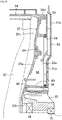
FIGS. 4 and5 , anair inlet 60 penetrating the wall is formed at a central region of theend wall 22, particularly, around an upper portion of the bearinghousing 23. Theair inlet 60 is disposed in the vicinity of the upper portion of the bearinghousing 23 since a resin is easily molded and it is difficult for water or bubbles to flow out of thetub 20 through theair inlet 60 during the washing or rinsing cycle among central regions. - In addition, an air inflow path is formed in the
washing machine 1 by mounting acover member 50 on the outer surface of theend wall 22 to prevent water or bubbles from flowing into theouter case 10 even after water or bubbles flow out of theair inlet 60. - The
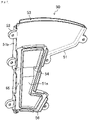
cover member 50 is illustrated inFIGS. 6 and7 . Thecover member 50 may be formed of an injection molded product of a plate type resin and may include acover body 51 having a shape corresponding to a structure of the outer surface of theend wall 22 andfastening flanges 52 protruding from a plurality of portions of an outer circumference of thecover body 51. - The
cover body 51 has a plate-shapedfirst plate part 51a and asecond plate part 51b that forms a channel having a small thickness at a portion of thefirst plate part 51a. Thesecond plate part 51b has anexternal air inlet 53 having a large width at one end thereof and communicates amiddle opening 54 formed at the center of thefirst plate part 51a with anexternal air input 53. - The
first plate part 51a has a ribfitting part 55 to engage thediametric rib 25 with thecircumferential rib 26. The ribfitting part 55 is formed in a rim shape along the outer periphery of a predetermined region of thefirst plate part 51a including themiddle opening 54. The ribfitting part 55 may be provided with anelastic packing 56. - Meanwhile, a path forming structure constituting an air inflow path may be formed using the
diametric rib 25 and thecircumferential rib 26 at a portion of theend wall 22 mounted with thecover body 51. - Specifically, as illustrated in
FIG. 4 ,fastening bosses 61 are provided at a plurality of locations of the outer surface of theend wall 22 to correspond to the arrangement of thefastening flanges 52. As thecircumferential ribs 26, a firstcircumferential rib 26a, a secondcircumferential rib 26b, a thirdcircumferential rib 26c, and a fourthcircumferential rib 26d are sequentially disposed on the outer surface of theend wall 22 from the center thereof at predetermined intervals. The firstcircumferential rib 26a and the thirdcircumferential rib 26c are sub ribs which are thinner than the secondcircumferential rib 26b and the fourthcircumferential rib 26d which are main ribs. The main ribs and the sub ribs are alternately arranged in the radial direction. - Also, the
diametric ribs 25 include thicker main ribs and thinner sub ribs which are alternately arranged in the circumferential direction. While maindiametric ribs 25a of thediametric ribs 25 extend from the central portion to the outer circumferential side, subdiametric ribs 25b of thediametric ribs 25 extend from the outer circumference of the firstcircumferential rib 26a. Protruding ends of thediametric ribs 25 and protruding ends of thecircumferential ribs 26 are connected with each other and located at the substantially same height. - The
air inlet 60 is formed to have a large area using a relatively large space between two adjacent maindiametric ribs 25a which are disposed closer to the center than the firstcircumferential rib 26a. Acommunication path 62 is formed in the radial direction by removing a half of one portion of the firstcircumferential rib 26a defined by adjacentsub diametric ribs 25b. - A reinforcing
rib 63 is installed between adjacent maindiametric ribs 25a disposed at both sides of theair inlet 60 at the center of theair inlet 60 in order to prevent a decrease in rigidity of theend wall 22 caused by formation of thecommunication path 62 and theair inlet 60. A portion of the secondcircumferential rib 26b (main rib) between the maindiametric rib 25a and thesub diametric rib 25b adjacent to thecommunication path 62 may be formed to have a relatively low height, e.g., about half as high as the other portions (lower rib 64). - As illustrated in
FIGS. 3 ,4 , and5 , thecover member 50 is mounted on theend wall 22 to cover a predetermined portion of the outer surface of theend wall 22 in a state where theexternal air inlet 53 faces upward by screw fixing each of thefastening flanges 52 overlapping each of thefastening bosses 61. Thus, the ribfitting part 55 is brought into close contact with a predetermined region (marked as oblique lines inFIG. 4 ) of the protruding ends of thediametric rib 25 and thecircumferential rib 26 via a packing 56, so that a closed space defined by thediametric rib 25 and thecircumferential rib 26 constituting the predetermined region, thewall surface 22a of theend wall 22 having theair inlet 60, and thefirst plate part 51a is formed on the outer surface of theend wall 22. - As illustrated in
FIG. 5 , the closedspace 65 communicates with thesecond plate part 51b via themiddle opening 54 by disposing thelower rib 64 below themiddle opening 54. Thus, the air inflow path is formed upward from the central region of the outer surface of theend wall 22, and theair inlet 60 communicates with the outside of thetub 20 through theexternal air inlet 53 located at an upper portion of thetub 20. - Since side walls of the air inflow path are defined by the
diametric rib 25 and thecircumferential rib 26 installed at the outer surface of theend wall 22, thecover member 50 has a simple structure. In addition, since the side walls are coupled with the thinsecond plate part 51b, the air inflow path may have a large volume without protruding from theend wall 22. As indicated by arrows ofFIG. 5 , air may be efficiently introduced into the center inside thetub 20. As the air inflow path protrudes farther from theend wall 22, the volume of thetub 20 should be reduced with respect to theouter case 10. However, there is no need to reduce the volume of thetub 20 in thewashing machine 1, thereby increasing the volume of thetub 20. - Even when water or bubbles flow out of the
tub 20 through theair inlet 60, the water or bubbles cannot flow out of theexternal air inlet 53 located at an upper portion of thetub 20 since the air inflow path is formed outside theair inlet 60. Thus, it is possible to prevent water or bubbles from flowing into theouter case 10. - Since the
lower rib 64 to prevent water or bubbles from flowing out is disposed in the middle of the air inflow path, water or bubbles may not flow into theouter case 10. -
FIG. 8A is a graph illustrating the relationship between changes in revolutions per minute (rpm) of a drum and the degree of displacement (mm) of a tub moving forward during spin-drying of a washing machine as a comparative embodiment before the air inlet and the air inflow path are formed.FIG. 8B is a graph illustrating the relationship between changes in rpm of a drum and the degree of displacement (mm) of a tub moving forward during spin-drying of a washing machine having the abovementioned air inlet and air inflow path according to the present disclosure. - As apparent from these graphs, while the tub moves forward 3 mm or more in the comparative embodiment, the tub does not move forward according to the present embodiment. Thus, it was confirmed that forward movement of the tub may be prevented by forming the air inlet.
- In addition,
FIG. 9 is a graph illustrating noise levels (PWL) during spin-drying of the washing machines according to the present embodiment and the comparative embodiment. The horizontal axis indicates frequency (Hz). - As a tub moves considerably farther forward tub, the tub pushes a diaphragm more, thereby increasing a noise level (about 160 Hz). The washing machine according to the present embodiment produces less noise than the washing machine according to the comparative embodiment. Therefore, it was confirmed that noise suppressing effect may be obtained during spin-drying according to the present embodiment.
-
FIG. 10 illustrates a first modified embodiment of thewashing machine 1 described above. Awashing machine 1A according to the first modified embodiment has the same structure except for an air inflow structure in comparison with theaforementioned washing machine 1, and thus the same reference numerals are used and detailed descriptions thereof will not be repeated. - In the
washing machine 1A, an opening (external air introduction opening 70) penetrating the wall surface of theend wall 22 is formed at an upper end portion, not the central region, of theend wall 22. Specifically, the external air introduction opening 70 is formed on thewall surface 22a of theend wall 22 defined by adjacent maindiametric rib 25a,diametric rib 25b, thirdcircumferential rib 26c, and fourthcircumferential rib 26d. - A bend-shaped
guide member 71 having a door-shaped cross-section, a closed upper end, and an open lower end is mounted on the inner surface of theend wall 22. Thus, a channel (inner channel 72) extending downward from the upper end along the inner surface of theend wall 22 is formed. - The upper end of the
guide member 71 is disposed to cover the external air introduction opening 70, and the lower end of theguide member 71 is disposed at the central region of theend wall 22. Thus, in thewashing machine 1A, an air inflow path is formed by theinner channel 72 communicating with the outside of thetub 20 via the external air introduction opening 70 and an air inlet is formed at alower end 72a of theinner channel 72 communicating with the inside of thetub 20. - Since air is also introduced into the central portion of the
tub 20 via the external air introduction opening 70, theinner channel 72, and thelower end 72a during spin-drying in thewashing machine 1A, a pressure difference is not caused in thetub 20 during spin-drying while preventing water or bubbles from flowing out thereof during washing or rinsing. - In the case of the
washing machine 1A, the structure of the outer surface of theend wall 22 may be the same as those of conventional washing machines. Thus, installation of thetub 20 with regard to theouter case 10 is not limited. Since the external air introduction opening 70 is formed at an outer peripheral portion of theend wall 22, rigidity of thetub 20 may be improved. -
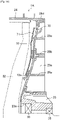
FIG. 11 illustrates a second modified embodiment of thewashing machine 1 described above. Awashing machine 1B according to the second modified embodiment has the same structure except for an air inflow structure in comparison with theaforementioned washing machine 1 or the washing machine A, and thus the same reference numerals are used and detailed descriptions thereof will not be repeated. - An air inflow structure of the
washing machine 1B includes an airingpath 80 formed by designing a gap between a rear end portion of thecircumferential wall 33 and themain body wall 24 to be greater than a gap between a middle portion of the circumferential wall 33 (between the front end portion and the rear end portion of the circumferential wall 33) and themain body wall 24. That is, the gap between thecircumferential wall 33 and themain body wall 24 is very small as a result of increasing the capacity of thedrum 30. Thus, air does not easily flow through the gap and reflux of air is inhibited, so that a large amount of air is discharged out of thetub 20 through thewater supply hose 6 or thedrain hose 7 causing a pressure difference in thetub 20. - Therefore, in the
washing machine 1B, the airingpath 80 is formed by increasing an inner diameter of the upper corner to be greater than the other portions in the rear end portion of thetub 20 to enlarge the gap therebetween. Since the rear end portion of thecircumferential wall 33 faces the airingpath 80, the rear end portion of thecircumferential wall 33 communicates with a gap (rear gap) between theend wall 22 of thetub 20 and theflange shaft 32 of thedrum 30. Thus, a part of air flowing out of from thecircumferential wall 33 of thedrum 30 may be returned to the central portion of thedrum 30 via the airingpath 80 and the rear gap. That is, in thiswashing machine 1B, the airingpath 80 and the rear gap constitute the air inflow structure. - In addition, the airing
path 80 may be formed by making an outer diameter of the rear end portion of thedrum 30 to be relatively small. -
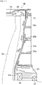
FIG. 12 illustrates a third modified embodiment of thewashing machine 1 described above. Awashing machine 1C according to the third modified embodiment has the same structure except for an air inflow structure in comparison with theaforementioned washing machine 1 or the like, and thus the same reference numerals are used and detailed descriptions thereof will not be repeated. - In the
washing machine 1C, anair outlet 90 facing thecircumferential wall 33 of thedrum 30 is formed on a rear end portion of themain body wall 24 of thetub 20. In addition, thetub 20 is provided with anauxiliary cover member 91 and the auxiliary cover member constitutes a bypass communicating with theexternal air inlet 53. Theair outlet 90 is covered by theauxiliary cover member 91. Thus, air flowing out of theair outlet 90 during spin-drying is returned to the central portion of thedrum 30 through the bypass, the air inflow path, and theair inlet 60, so that a pressure difference is not caused in thetub 20, thereby suppressing the noise. -
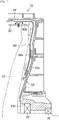
FIG. 13 illustrates a fourth embodiment of thewashing machine 1 described above. A washing machine ID according to the fourth modified embodiment has the same structure except for an air inflow structure in comparison with theaforementioned washing machine 1 or the like, and thus the same reference numerals are used and detailed descriptions thereof will not be repeated. - An air inflow structure of the washing machine ID includes a
baffle plate 80 disposed between the rear end portion of thedrum 30 and thetub 20. - Specifically, the
baffle plate 80 is disposed to expand in a gap between the inner surface of thetub 20 from a rear upper portion of themain body wall 24 to at least the central region of theend wall 22 and the outer surface of the rear end portion (particularly, the rear end portion of thecircumferential wall 3 and the flange shaft 32) of thedrum 30 and to face the inner surface of thetub 20 at an interval. - The
baffle plate 80 is formed of a thin plate member and includes amain wall 80a expanding from the central portion of theend wall 22 to the upper end portion thereof along the inner surface of thewall surface 22a and asub wall 80b connected to themain wall 80a and expanding forward along the inner surface of themain body wall 24. - An air path (baffle path) that induces an airflow from a front end portion of the
sub wall 80b to the center of themain wall 80a is formed by the gap between thebaffle plate 80 and the inner surface of thetub 20. A wall mount type or pillar type support member (not shown) is provided on the inner surface of thetub 20 facing thebaffle plate 80 not to block the airflow and thebaffle plate 80 is supported by the support member. - During spin-drying, air flowing out from the rear end portion of the
drum 30 in the circumferential direction collides with the inner surface of thetub 20 and flows out of thetub 20 or is diffused forming turbulence if there is nosub wall 80b. However, if there is thesub wall 80b, the air collides with theside wall 80b and the baffle path is not influenced thereby, and thus air may be smoothly introduced into the baffle path. - An airflow in the radially outward direction from the central portion of the
drum 30 is formed in the gap between theflange shaft 32 of thedrum 30 and the inner surface of thewall surface 22a of theend wall 22 as shown by dashed lines ofFIG. 13 when thedrum 30 rotates at a high speed. Particularly, due to thearm portions 32b, a strong airflow may easily be generated by stirring thearm portions 32b. Thus, it is difficult for air to flow toward the central portion of thedrum 30 in this gap. - Thus, the gap may be partitioned into one side of the
flange shaft 32 and the other side of theend wall 22 by installing thebaffle plate 80 and influence of a reverse airflow is not applied to the baffle path. Thus, air may be smoothly introduced toward the central portion of thedrum 30. - Therefore, air flowing out of the
drum 30 in the radially outward direction during spin-drying may be smoothly returned to the central portion of thedrum 30 via the baffle path, and thus a pressure difference is not caused, thereby suppressing the noise. - The drum type washing machine according to the present disclosure is not limited to the aforementioned embodiments and may also include various other configurations. For example, although the air inlet is formed at the central region of the
end wall 22 of thetub 20 in thewashing machine 1 according to the present embodiment, an air inlet may also be formed at the center of thedoor 18 by mounting theguide member 71 described above with reference to the modified embodiments on the inner surface of thedoor 18 or the like. Similarly, the air inflow structure of each modified embodiment may also be installed at a front portion of thedrum 30 or at both front and rear portions thereof. - Although the present disclosure has been described with an exemplary embodiment, various changes and modifications may be suggested to one skilled in the art. It is intended that the present disclosure encompass such changes and modifications as fall within the scope of the appended claims.
Claims (8)
- A washing machine (1) comprising:a case (10) including a front panel (11) having a laundry loading/unloading opening (17) through which laundry is introduced;a door (18) mounted at the case (10) to open or close the laundry loading/unloading opening (17);a tub (20) disposed inside the case (10), wherein the tub (20) includes an opening (21) connected to the laundry loading/unloading opening (17) and an end wall (22) facing the laundry loading/unloading opening (17);a drum (30) rotatably disposed inside the tub (20);an air inflow channel configured to guide air to flow through an air inlet (60) formed at one portion of the end wall (22) into a central portion of the drum (30) in which a pressure decreases while the drum (30) rotates; anda cover member (50) mounted on an outer surface of the end wall (22) to constitute the air inflow channel and including an external air inlet (53) through which air is introduced,wherein the external air inlet (53) is disposed at an upper portion of the tub (20).
- The washing machine according to claim 1, wherein the air inflow channel further includes an air inlet formed at a rear surface of the door (18).
- The washing machine according to claim 1, wherein the air inlet (60) is formed at a position higher than a rotational axis of the drum (30).
- The washing machine according to claim 1, wherein a rib (25) radially extending from a centre of the end wall (22) is provided on the outer surface of the end wall (22), and
the rib (25) constitutes one surface of the air inflow channel. - The washing machine according to claim 4, wherein the cover member (50) further comprises a rib fitting part (55) fitted to the rib (25).
- The washing machine according to claim 1, wherein the tub (20) further comprises a main body wall (24) that is cylindrical,an air outlet (90) to discharge air is formed at one portion of the main body wall (24), andthe air inflow channel connects the air outlet (90) with the air inlet (60).
- The washing machine according to claim 6, further comprising:
an auxiliary cover member (91) mounted on an outer surface of the main body wall (24) and configured to guide air from the air outlet (90) to an upper portion of the cover member (50). - The washing machine according to claim 1, wherein the external air inlet (53) is disposed at an upper portion than the air inlet (60) to prevent water contained in the tub (20) from flowing out of the tub (20) via the air inflow channel.
Applications Claiming Priority (4)
| Application Number | Priority Date | Filing Date | Title |
|---|---|---|---|
| JP2016228377 | 2016-11-24 | ||
| JP2017042126A JP2018086229A (en) | 2016-11-24 | 2017-03-06 | Drum type washing machine |
| KR1020170094635A KR102381040B1 (en) | 2016-11-24 | 2017-07-26 | Washing machine |
| PCT/KR2017/011887 WO2018097493A1 (en) | 2016-11-24 | 2017-10-26 | Washing machine |
Publications (3)
| Publication Number | Publication Date |
|---|---|
| EP3526388A1 EP3526388A1 (en) | 2019-08-21 |
| EP3526388A4 EP3526388A4 (en) | 2019-09-04 |
| EP3526388B1 true EP3526388B1 (en) | 2022-04-06 |
Family
ID=62195570
Family Applications (1)
| Application Number | Title | Priority Date | Filing Date |
|---|---|---|---|
| EP17873763.1A Active EP3526388B1 (en) | 2016-11-24 | 2017-10-26 | Washing machine |
Country Status (3)
| Country | Link |
|---|---|
| US (1) | US10538871B2 (en) |
| EP (1) | EP3526388B1 (en) |
| WO (1) | WO2018097493A1 (en) |
Families Citing this family (2)
| Publication number | Priority date | Publication date | Assignee | Title |
|---|---|---|---|---|
| CN111424403B (en) * | 2018-12-24 | 2023-05-16 | 重庆海尔洗衣机有限公司 | Wall-mounted washing machine |
| CN111691129B (en) * | 2019-03-13 | 2022-12-27 | 青岛海尔洗涤电器有限公司 | Drum washing machine |
Family Cites Families (17)
| Publication number | Priority date | Publication date | Assignee | Title |
|---|---|---|---|---|
| US2957330A (en) | 1954-02-26 | 1960-10-25 | Kermit R Cline | Combination washer and drier |
| ES242354Y (en) | 1979-03-16 | 1979-11-16 | DRYING DEVICE FOR CLOTHES WASHING MACHINES. | |
| JPS561198A (en) | 1979-06-20 | 1981-01-08 | Hitachi Ltd | Full automatic drying washing machine |
| KR100287027B1 (en) | 1996-03-14 | 2001-04-16 | 니시무로 타이죠 | Drum washer |
| US6088932A (en) | 1997-12-30 | 2000-07-18 | Amana Company, L.P. | Efficiency clothes dryer |
| KR100446758B1 (en) | 2001-08-22 | 2004-09-01 | 엘지전자 주식회사 | Diryer |
| JP3605067B2 (en) * | 2001-11-14 | 2004-12-22 | 三洋電機株式会社 | Drum type washer / dryer |
| US7017282B2 (en) | 2003-07-24 | 2006-03-28 | Samsung Electronics Co., Ltd. | Drying apparatus and washing machine having the same |
| JP4293114B2 (en) | 2004-11-09 | 2009-07-08 | パナソニック株式会社 | Drum type washer / dryer |
| JP4535968B2 (en) | 2005-08-23 | 2010-09-01 | シャープ株式会社 | Washing machine |
| JP4607718B2 (en) | 2005-09-08 | 2011-01-05 | パナソニック株式会社 | Drum washing machine |
| EP2019163B1 (en) | 2007-07-26 | 2018-02-28 | Candy S.p.A. | Washer dryer machine |
| WO2010123612A2 (en) | 2009-02-03 | 2010-10-28 | Mesocoat, Inc. | Coatings, composition, and method related to non-spalling low density hardface coatings |
| EP2412861B1 (en) | 2010-07-30 | 2013-03-13 | Electrolux Home Products Corporation N.V. | Laundry washing and drying machine |
| JP2012187235A (en) | 2011-03-10 | 2012-10-04 | Hitachi Appliances Inc | Drum washing machine |
| DE102011086142A1 (en) | 2011-11-11 | 2013-05-16 | BSH Bosch und Siemens Hausgeräte GmbH | Washing machine with reduced rewet and process for its operation |
| CN202865651U (en) | 2012-10-12 | 2013-04-10 | 苏州三星电子有限公司 | Condensing type drying device |
-
2017
- 2017-10-24 US US15/792,600 patent/US10538871B2/en active Active
- 2017-10-26 WO PCT/KR2017/011887 patent/WO2018097493A1/en unknown
- 2017-10-26 EP EP17873763.1A patent/EP3526388B1/en active Active
Non-Patent Citations (1)
| Title |
|---|
| None * |
Also Published As
| Publication number | Publication date |
|---|---|
| US10538871B2 (en) | 2020-01-21 |
| EP3526388A1 (en) | 2019-08-21 |
| WO2018097493A1 (en) | 2018-05-31 |
| EP3526388A4 (en) | 2019-09-04 |
| US20180142398A1 (en) | 2018-05-24 |
Similar Documents
| Publication | Publication Date | Title |
|---|---|---|
| US9328442B2 (en) | Washing machine | |
| EP2435612B1 (en) | Laundry machine | |
| EP3582373B1 (en) | Brushless dc motor and drain pump having the same | |
| US20140033772A1 (en) | Washing machine | |
| JP2007167263A (en) | Drum-type washing machine | |
| EP3526388B1 (en) | Washing machine | |
| JP2010094227A (en) | Drum washing machine | |
| US20230323588A1 (en) | Washing machine | |
| US10655262B2 (en) | Laundry treating appliance with a tub ring | |
| EP3850147B1 (en) | Water transmission device and washing machine including the same | |
| JP6286279B2 (en) | Washing machine | |
| CN111945392B (en) | Drain pump reaches clothing processing apparatus including it | |
| KR102549126B1 (en) | Washing Machine | |
| CN107429465B (en) | Washing machine | |
| JP5050177B2 (en) | Drum washing machine | |
| JP6712245B2 (en) | Washing machine | |
| JP2007209502A (en) | Drum type washing machine | |
| KR102381040B1 (en) | Washing machine | |
| CN110832133B (en) | Clothes treating apparatus | |
| KR20170089709A (en) | Drain Pump and Washing Machine Having the Same | |
| JP6967363B2 (en) | Washing machine | |
| JP6223274B2 (en) | Washing machine | |
| JP2018086229A (en) | Drum type washing machine | |
| JP2023173095A (en) | washing machine | |
| JP2023180279A (en) | washing machine |
Legal Events
| Date | Code | Title | Description |
|---|---|---|---|
| STAA | Information on the status of an ep patent application or granted ep patent |
Free format text: STATUS: THE INTERNATIONAL PUBLICATION HAS BEEN MADE |
|
| PUAI | Public reference made under article 153(3) epc to a published international application that has entered the european phase |
Free format text: ORIGINAL CODE: 0009012 |
|
| STAA | Information on the status of an ep patent application or granted ep patent |
Free format text: STATUS: REQUEST FOR EXAMINATION WAS MADE |
|
| 17P | Request for examination filed |
Effective date: 20190513 |
|
| AK | Designated contracting states |
Kind code of ref document: A1 Designated state(s): AL AT BE BG CH CY CZ DE DK EE ES FI FR GB GR HR HU IE IS IT LI LT LU LV MC MK MT NL NO PL PT RO RS SE SI SK SM TR |
|
| AX | Request for extension of the european patent |
Extension state: BA ME |
|
| A4 | Supplementary search report drawn up and despatched |
Effective date: 20190802 |
|
| RIC1 | Information provided on ipc code assigned before grant |
Ipc: D06F 37/26 20060101ALI20190729BHEP Ipc: D06F 37/22 20060101AFI20190729BHEP |
|
| DAV | Request for validation of the european patent (deleted) | ||
| DAX | Request for extension of the european patent (deleted) | ||
| STAA | Information on the status of an ep patent application or granted ep patent |
Free format text: STATUS: EXAMINATION IS IN PROGRESS |
|
| 17Q | First examination report despatched |
Effective date: 20200723 |
|
| STAA | Information on the status of an ep patent application or granted ep patent |
Free format text: STATUS: EXAMINATION IS IN PROGRESS |
|
| GRAP | Despatch of communication of intention to grant a patent |
Free format text: ORIGINAL CODE: EPIDOSNIGR1 |
|
| STAA | Information on the status of an ep patent application or granted ep patent |
Free format text: STATUS: GRANT OF PATENT IS INTENDED |
|
| INTG | Intention to grant announced |
Effective date: 20220117 |
|
| GRAS | Grant fee paid |
Free format text: ORIGINAL CODE: EPIDOSNIGR3 |
|
| GRAA | (expected) grant |
Free format text: ORIGINAL CODE: 0009210 |
|
| STAA | Information on the status of an ep patent application or granted ep patent |
Free format text: STATUS: THE PATENT HAS BEEN GRANTED |
|
| AK | Designated contracting states |
Kind code of ref document: B1 Designated state(s): AL AT BE BG CH CY CZ DE DK EE ES FI FR GB GR HR HU IE IS IT LI LT LU LV MC MK MT NL NO PL PT RO RS SE SI SK SM TR |
|
| REG | Reference to a national code |
Ref country code: GB Ref legal event code: FG4D |
|
| REG | Reference to a national code |
Ref country code: CH Ref legal event code: EP |
|
| REG | Reference to a national code |
Ref country code: AT Ref legal event code: REF Ref document number: 1481432 Country of ref document: AT Kind code of ref document: T Effective date: 20220415 |
|
| REG | Reference to a national code |
Ref country code: IE Ref legal event code: FG4D |
|
| REG | Reference to a national code |
Ref country code: DE Ref legal event code: R096 Ref document number: 602017055740 Country of ref document: DE |
|
| REG | Reference to a national code |
Ref country code: LT Ref legal event code: MG9D |
|
| REG | Reference to a national code |
Ref country code: NL Ref legal event code: MP Effective date: 20220406 |
|
| REG | Reference to a national code |
Ref country code: AT Ref legal event code: MK05 Ref document number: 1481432 Country of ref document: AT Kind code of ref document: T Effective date: 20220406 |
|
| PG25 | Lapsed in a contracting state [announced via postgrant information from national office to epo] |
Ref country code: NL Free format text: LAPSE BECAUSE OF FAILURE TO SUBMIT A TRANSLATION OF THE DESCRIPTION OR TO PAY THE FEE WITHIN THE PRESCRIBED TIME-LIMIT Effective date: 20220406 |
|
| PG25 | Lapsed in a contracting state [announced via postgrant information from national office to epo] |
Ref country code: SE Free format text: LAPSE BECAUSE OF FAILURE TO SUBMIT A TRANSLATION OF THE DESCRIPTION OR TO PAY THE FEE WITHIN THE PRESCRIBED TIME-LIMIT Effective date: 20220406 Ref country code: PT Free format text: LAPSE BECAUSE OF FAILURE TO SUBMIT A TRANSLATION OF THE DESCRIPTION OR TO PAY THE FEE WITHIN THE PRESCRIBED TIME-LIMIT Effective date: 20220808 Ref country code: NO Free format text: LAPSE BECAUSE OF FAILURE TO SUBMIT A TRANSLATION OF THE DESCRIPTION OR TO PAY THE FEE WITHIN THE PRESCRIBED TIME-LIMIT Effective date: 20220706 Ref country code: LT Free format text: LAPSE BECAUSE OF FAILURE TO SUBMIT A TRANSLATION OF THE DESCRIPTION OR TO PAY THE FEE WITHIN THE PRESCRIBED TIME-LIMIT Effective date: 20220406 Ref country code: HR Free format text: LAPSE BECAUSE OF FAILURE TO SUBMIT A TRANSLATION OF THE DESCRIPTION OR TO PAY THE FEE WITHIN THE PRESCRIBED TIME-LIMIT Effective date: 20220406 Ref country code: GR Free format text: LAPSE BECAUSE OF FAILURE TO SUBMIT A TRANSLATION OF THE DESCRIPTION OR TO PAY THE FEE WITHIN THE PRESCRIBED TIME-LIMIT Effective date: 20220707 Ref country code: FI Free format text: LAPSE BECAUSE OF FAILURE TO SUBMIT A TRANSLATION OF THE DESCRIPTION OR TO PAY THE FEE WITHIN THE PRESCRIBED TIME-LIMIT Effective date: 20220406 Ref country code: ES Free format text: LAPSE BECAUSE OF FAILURE TO SUBMIT A TRANSLATION OF THE DESCRIPTION OR TO PAY THE FEE WITHIN THE PRESCRIBED TIME-LIMIT Effective date: 20220406 Ref country code: BG Free format text: LAPSE BECAUSE OF FAILURE TO SUBMIT A TRANSLATION OF THE DESCRIPTION OR TO PAY THE FEE WITHIN THE PRESCRIBED TIME-LIMIT Effective date: 20220706 Ref country code: AT Free format text: LAPSE BECAUSE OF FAILURE TO SUBMIT A TRANSLATION OF THE DESCRIPTION OR TO PAY THE FEE WITHIN THE PRESCRIBED TIME-LIMIT Effective date: 20220406 |
|
| PG25 | Lapsed in a contracting state [announced via postgrant information from national office to epo] |
Ref country code: RS Free format text: LAPSE BECAUSE OF FAILURE TO SUBMIT A TRANSLATION OF THE DESCRIPTION OR TO PAY THE FEE WITHIN THE PRESCRIBED TIME-LIMIT Effective date: 20220406 Ref country code: PL Free format text: LAPSE BECAUSE OF FAILURE TO SUBMIT A TRANSLATION OF THE DESCRIPTION OR TO PAY THE FEE WITHIN THE PRESCRIBED TIME-LIMIT Effective date: 20220406 Ref country code: LV Free format text: LAPSE BECAUSE OF FAILURE TO SUBMIT A TRANSLATION OF THE DESCRIPTION OR TO PAY THE FEE WITHIN THE PRESCRIBED TIME-LIMIT Effective date: 20220406 Ref country code: IS Free format text: LAPSE BECAUSE OF FAILURE TO SUBMIT A TRANSLATION OF THE DESCRIPTION OR TO PAY THE FEE WITHIN THE PRESCRIBED TIME-LIMIT Effective date: 20220806 |
|
| REG | Reference to a national code |
Ref country code: DE Ref legal event code: R097 Ref document number: 602017055740 Country of ref document: DE |
|
| PG25 | Lapsed in a contracting state [announced via postgrant information from national office to epo] |
Ref country code: SM Free format text: LAPSE BECAUSE OF FAILURE TO SUBMIT A TRANSLATION OF THE DESCRIPTION OR TO PAY THE FEE WITHIN THE PRESCRIBED TIME-LIMIT Effective date: 20220406 Ref country code: SK Free format text: LAPSE BECAUSE OF FAILURE TO SUBMIT A TRANSLATION OF THE DESCRIPTION OR TO PAY THE FEE WITHIN THE PRESCRIBED TIME-LIMIT Effective date: 20220406 Ref country code: RO Free format text: LAPSE BECAUSE OF FAILURE TO SUBMIT A TRANSLATION OF THE DESCRIPTION OR TO PAY THE FEE WITHIN THE PRESCRIBED TIME-LIMIT Effective date: 20220406 Ref country code: EE Free format text: LAPSE BECAUSE OF FAILURE TO SUBMIT A TRANSLATION OF THE DESCRIPTION OR TO PAY THE FEE WITHIN THE PRESCRIBED TIME-LIMIT Effective date: 20220406 Ref country code: DK Free format text: LAPSE BECAUSE OF FAILURE TO SUBMIT A TRANSLATION OF THE DESCRIPTION OR TO PAY THE FEE WITHIN THE PRESCRIBED TIME-LIMIT Effective date: 20220406 Ref country code: CZ Free format text: LAPSE BECAUSE OF FAILURE TO SUBMIT A TRANSLATION OF THE DESCRIPTION OR TO PAY THE FEE WITHIN THE PRESCRIBED TIME-LIMIT Effective date: 20220406 |
|
| PLBE | No opposition filed within time limit |
Free format text: ORIGINAL CODE: 0009261 |
|
| STAA | Information on the status of an ep patent application or granted ep patent |
Free format text: STATUS: NO OPPOSITION FILED WITHIN TIME LIMIT |
|
| 26N | No opposition filed |
Effective date: 20230110 |
|
| PG25 | Lapsed in a contracting state [announced via postgrant information from national office to epo] |
Ref country code: AL Free format text: LAPSE BECAUSE OF FAILURE TO SUBMIT A TRANSLATION OF THE DESCRIPTION OR TO PAY THE FEE WITHIN THE PRESCRIBED TIME-LIMIT Effective date: 20220406 |
|
| PG25 | Lapsed in a contracting state [announced via postgrant information from national office to epo] |
Ref country code: SI Free format text: LAPSE BECAUSE OF FAILURE TO SUBMIT A TRANSLATION OF THE DESCRIPTION OR TO PAY THE FEE WITHIN THE PRESCRIBED TIME-LIMIT Effective date: 20220406 Ref country code: MC Free format text: LAPSE BECAUSE OF FAILURE TO SUBMIT A TRANSLATION OF THE DESCRIPTION OR TO PAY THE FEE WITHIN THE PRESCRIBED TIME-LIMIT Effective date: 20220406 |
|
| REG | Reference to a national code |
Ref country code: CH Ref legal event code: PL |
|
| REG | Reference to a national code |
Ref country code: BE Ref legal event code: MM Effective date: 20221031 |
|
| PG25 | Lapsed in a contracting state [announced via postgrant information from national office to epo] |
Ref country code: LU Free format text: LAPSE BECAUSE OF NON-PAYMENT OF DUE FEES Effective date: 20221026 |
|
| PG25 | Lapsed in a contracting state [announced via postgrant information from national office to epo] |
Ref country code: LI Free format text: LAPSE BECAUSE OF NON-PAYMENT OF DUE FEES Effective date: 20221031 Ref country code: FR Free format text: LAPSE BECAUSE OF NON-PAYMENT OF DUE FEES Effective date: 20221031 Ref country code: CH Free format text: LAPSE BECAUSE OF NON-PAYMENT OF DUE FEES Effective date: 20221031 |
|
| PG25 | Lapsed in a contracting state [announced via postgrant information from national office to epo] |
Ref country code: BE Free format text: LAPSE BECAUSE OF NON-PAYMENT OF DUE FEES Effective date: 20221031 |
|
| PG25 | Lapsed in a contracting state [announced via postgrant information from national office to epo] |
Ref country code: IE Free format text: LAPSE BECAUSE OF NON-PAYMENT OF DUE FEES Effective date: 20221026 |
|
| PGFP | Annual fee paid to national office [announced via postgrant information from national office to epo] |
Ref country code: GB Payment date: 20230920 Year of fee payment: 7 |
|
| PG25 | Lapsed in a contracting state [announced via postgrant information from national office to epo] |
Ref country code: IT Free format text: LAPSE BECAUSE OF FAILURE TO SUBMIT A TRANSLATION OF THE DESCRIPTION OR TO PAY THE FEE WITHIN THE PRESCRIBED TIME-LIMIT Effective date: 20220406 |
|
| PGFP | Annual fee paid to national office [announced via postgrant information from national office to epo] |
Ref country code: DE Payment date: 20230920 Year of fee payment: 7 |
|
| PG25 | Lapsed in a contracting state [announced via postgrant information from national office to epo] |
Ref country code: HU Free format text: LAPSE BECAUSE OF FAILURE TO SUBMIT A TRANSLATION OF THE DESCRIPTION OR TO PAY THE FEE WITHIN THE PRESCRIBED TIME-LIMIT; INVALID AB INITIO Effective date: 20171026 |
|
| PG25 | Lapsed in a contracting state [announced via postgrant information from national office to epo] |
Ref country code: CY Free format text: LAPSE BECAUSE OF FAILURE TO SUBMIT A TRANSLATION OF THE DESCRIPTION OR TO PAY THE FEE WITHIN THE PRESCRIBED TIME-LIMIT Effective date: 20220406 |
|
| PG25 | Lapsed in a contracting state [announced via postgrant information from national office to epo] |
Ref country code: MK Free format text: LAPSE BECAUSE OF FAILURE TO SUBMIT A TRANSLATION OF THE DESCRIPTION OR TO PAY THE FEE WITHIN THE PRESCRIBED TIME-LIMIT Effective date: 20220406 |
|
| PG25 | Lapsed in a contracting state [announced via postgrant information from national office to epo] |
Ref country code: TR Free format text: LAPSE BECAUSE OF FAILURE TO SUBMIT A TRANSLATION OF THE DESCRIPTION OR TO PAY THE FEE WITHIN THE PRESCRIBED TIME-LIMIT Effective date: 20220406 |