EP3526069B1 - A system for the reduction of slosh noises in a fuel tank - Google Patents
A system for the reduction of slosh noises in a fuel tank Download PDFInfo
- Publication number
- EP3526069B1 EP3526069B1 EP17780755.9A EP17780755A EP3526069B1 EP 3526069 B1 EP3526069 B1 EP 3526069B1 EP 17780755 A EP17780755 A EP 17780755A EP 3526069 B1 EP3526069 B1 EP 3526069B1
- Authority
- EP
- European Patent Office
- Prior art keywords
- fuel tank
- tank
- wall
- side wing
- fuel
- Prior art date
- Legal status (The legal status is an assumption and is not a legal conclusion. Google has not performed a legal analysis and makes no representation as to the accuracy of the status listed.)
- Not-in-force
Links
Images
Classifications
-
- B—PERFORMING OPERATIONS; TRANSPORTING
- B60—VEHICLES IN GENERAL
- B60K—ARRANGEMENT OR MOUNTING OF PROPULSION UNITS OR OF TRANSMISSIONS IN VEHICLES; ARRANGEMENT OR MOUNTING OF PLURAL DIVERSE PRIME-MOVERS IN VEHICLES; AUXILIARY DRIVES FOR VEHICLES; INSTRUMENTATION OR DASHBOARDS FOR VEHICLES; ARRANGEMENTS IN CONNECTION WITH COOLING, AIR INTAKE, GAS EXHAUST OR FUEL SUPPLY OF PROPULSION UNITS IN VEHICLES
- B60K15/00—Arrangement in connection with fuel supply of combustion engines or other fuel consuming energy converters, e.g. fuel cells; Mounting or construction of fuel tanks
- B60K15/03—Fuel tanks
- B60K15/077—Fuel tanks with means modifying or controlling distribution or motion of fuel, e.g. to prevent noise, surge, splash or fuel starvation
-
- B—PERFORMING OPERATIONS; TRANSPORTING
- B60—VEHICLES IN GENERAL
- B60K—ARRANGEMENT OR MOUNTING OF PROPULSION UNITS OR OF TRANSMISSIONS IN VEHICLES; ARRANGEMENT OR MOUNTING OF PLURAL DIVERSE PRIME-MOVERS IN VEHICLES; AUXILIARY DRIVES FOR VEHICLES; INSTRUMENTATION OR DASHBOARDS FOR VEHICLES; ARRANGEMENTS IN CONNECTION WITH COOLING, AIR INTAKE, GAS EXHAUST OR FUEL SUPPLY OF PROPULSION UNITS IN VEHICLES
- B60K15/00—Arrangement in connection with fuel supply of combustion engines or other fuel consuming energy converters, e.g. fuel cells; Mounting or construction of fuel tanks
- B60K15/03—Fuel tanks
- B60K2015/03243—Fuel tanks characterised by special pumps, the mounting thereof
-
- B—PERFORMING OPERATIONS; TRANSPORTING
- B60—VEHICLES IN GENERAL
- B60K—ARRANGEMENT OR MOUNTING OF PROPULSION UNITS OR OF TRANSMISSIONS IN VEHICLES; ARRANGEMENT OR MOUNTING OF PLURAL DIVERSE PRIME-MOVERS IN VEHICLES; AUXILIARY DRIVES FOR VEHICLES; INSTRUMENTATION OR DASHBOARDS FOR VEHICLES; ARRANGEMENTS IN CONNECTION WITH COOLING, AIR INTAKE, GAS EXHAUST OR FUEL SUPPLY OF PROPULSION UNITS IN VEHICLES
- B60K15/00—Arrangement in connection with fuel supply of combustion engines or other fuel consuming energy converters, e.g. fuel cells; Mounting or construction of fuel tanks
- B60K15/03—Fuel tanks
- B60K2015/03328—Arrangements or special measures related to fuel tanks or fuel handling
- B60K2015/0344—Arrangements or special measures related to fuel tanks or fuel handling comprising baffles
-
- B—PERFORMING OPERATIONS; TRANSPORTING
- B60—VEHICLES IN GENERAL
- B60K—ARRANGEMENT OR MOUNTING OF PROPULSION UNITS OR OF TRANSMISSIONS IN VEHICLES; ARRANGEMENT OR MOUNTING OF PLURAL DIVERSE PRIME-MOVERS IN VEHICLES; AUXILIARY DRIVES FOR VEHICLES; INSTRUMENTATION OR DASHBOARDS FOR VEHICLES; ARRANGEMENTS IN CONNECTION WITH COOLING, AIR INTAKE, GAS EXHAUST OR FUEL SUPPLY OF PROPULSION UNITS IN VEHICLES
- B60K15/00—Arrangement in connection with fuel supply of combustion engines or other fuel consuming energy converters, e.g. fuel cells; Mounting or construction of fuel tanks
- B60K15/03—Fuel tanks
- B60K15/077—Fuel tanks with means modifying or controlling distribution or motion of fuel, e.g. to prevent noise, surge, splash or fuel starvation
- B60K2015/0775—Fuel tanks with means modifying or controlling distribution or motion of fuel, e.g. to prevent noise, surge, splash or fuel starvation for reducing movement or slash noise of fuel
-
- B—PERFORMING OPERATIONS; TRANSPORTING
- B60—VEHICLES IN GENERAL
- B60K—ARRANGEMENT OR MOUNTING OF PROPULSION UNITS OR OF TRANSMISSIONS IN VEHICLES; ARRANGEMENT OR MOUNTING OF PLURAL DIVERSE PRIME-MOVERS IN VEHICLES; AUXILIARY DRIVES FOR VEHICLES; INSTRUMENTATION OR DASHBOARDS FOR VEHICLES; ARRANGEMENTS IN CONNECTION WITH COOLING, AIR INTAKE, GAS EXHAUST OR FUEL SUPPLY OF PROPULSION UNITS IN VEHICLES
- B60K15/00—Arrangement in connection with fuel supply of combustion engines or other fuel consuming energy converters, e.g. fuel cells; Mounting or construction of fuel tanks
- B60K15/03—Fuel tanks
- B60K15/077—Fuel tanks with means modifying or controlling distribution or motion of fuel, e.g. to prevent noise, surge, splash or fuel starvation
- B60K2015/0777—Fuel tanks with means modifying or controlling distribution or motion of fuel, e.g. to prevent noise, surge, splash or fuel starvation in-tank reservoirs or baffles integrally manufactured with the fuel Tank
Definitions
- the present invention relates to a system for the reduction of slosh noises (or splashing noises) in a fuel tank of a motor vehicle.
- Fuel tanks of motor vehicles generally comprise internal accessories.
- One particular case of such accessories is that of noise reduction baffles, the purpose of which is to absorb the noise (“slosh” noise) associated with the waves which may be generated inside the tank when the vehicle accelerates rapidly, brakes, turns, etc.
- Such baffles are also known as “anti-slosh baffles" in the automotive field.
- US4526286 discloses a plastic fuel tank having an integral splash baffle.
- US6408979 discloses a plastic fuel tank having a baffle with a filter media material.
- EP2323863 discloses a plastic fuel tank having a baffle with compression springs.
- a fuel tank baffle assembly provided for installation in a fuel tank is known from US 2014/144914 A1 .
- the object of the present invention is to provide an alternative system for the reduction of slosh noises of a fuel tank.
- the side wing is configured to slow the velocity of the moving waves and to guide the waves toward the damping rib.
- the side wing may be oriented such that the wave is guided to a top wall and/or a sidewall portion of the tank, and the wave reflects back from the wall portion and propagates toward the damping rib at a particularly low velocity.
- the wall portion may be shaped (i.e. formed) such that the wave deflected by the side wing flows silently along the wall portion.
- the wall portion of the fuel tank may be rounded in order to assist in reducing energy of any waves of liquid fuel that come in contact with the wall portion of the fuel tank.
- the side wing may be oriented such that the wave is guided directly to the damping rib at a particularly low velocity.
- the damping rib is configured to disperse the deflected or reflected waves to reduce the energy of the waves and reduce sloshing or other noises associated with movement of liquid fuel in the tank.
- a plurality of damping ribs may be formed at the top and/or bottom and/or side wall of the tank and may be arranged one to another in a manner such that it creates a cascading damping effect (i.e. successive dispersion of the energy of the waves).
- the side wing(s) may have any geometric shape including, for example, rectangular, triangular or any other shape.
- the side wing may be planar or non-planar (i.e. curved).
- the side wing is a rectangular plate.
- the side wing(s) may be shaped and oriented so that slosh noises do not occur when the flow of fuel impinges onto the side wing(s).
- a sharp impingement of the fuel onto the side wing(s) can be further damped in a simple way if the side wing(s) are designed resiliently.
- the side wing(s) may be attached to the main body by any means known in the art (welding, snap-riveting, screwing, gluing, etc.).
- the main body and the side wing(s) may be made of thermoplastic, for example HDPE.
- the side wing(s) is(are) molded in one piece with the main body.
- Such assembly can be easily manipulated and attached inside the fuel tank.
- such assembly can be attached during the manufacturing of the fuel tank.
- it can be used the attachment process disclosed in document EP2155469 in the name of the Applicant.
- the term "fuel tank” is understood to mean a substantially impermeable tank that can store fuel under diverse and varied environmental and usage conditions.
- the fuel tank according to the invention is preferably made of plastic, that is to say made of a material comprising at least one synthetic resin polymer. Particularly suitable are plastics that belong to the category of thermoplastics.
- thermoplastic is understood to mean any thermoplastic polymer, including thermoplastic elastomers, and blends thereof.
- polymer is understood to mean both homopolymers and copolymers (especially binary or ternary copolymers). Examples of such copolymers are: random copolymers, linear block copolymers, other block copolymers and graft copolymers.
- One polymer often employed is high-density polyethylene (HDPE). However, excellent results may also be obtained with polyamide.
- HDPE high-density polyethylene
- the tank also comprises a layer of a fuel-impermeable resin such as, for example, EVOH (a partially hydrolysed ethylene/vinyl acetate copolymer).
- EVOH a partially hydrolysed ethylene/vinyl acetate copolymer
- the tank may be subjected to a surface treatment (fluorination or sulphonation) for the purpose of making it impermeable to fuel.
- the fuel tank is produced from plastic by the blow molding method or by the injection molding method.
- the damping rib(s) is (are) molded in one piece with the top and/or bottom and/or side wall of the tank and manufactured at the same time as when the tank is produced.
- the damping rib(s) may also be formed on the top and/or bottom and/or side wall of the tank as a mounted portion, i.e. may be attached to a wall of the tank by any means known in the art (welding, snap-riveting, screwing, gluing, etc.).
- a motor vehicle comprising the fuel tank as described above.
- the following drawings are illustrative of exemplary embodiments and therefore do not limit the scope of the invention. They are presented to assist in providing a proper understanding of the invention.
- the present invention will hereinafter be described in conjunction with the accompanying figures, in which:
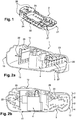
- FIG 1 represents a perspective view of a baffle according to a particular embodiment of the present invention.
- the baffle 2 is intended for use in a slosh noises reduction system for a fuel tank which will be further described with reference to Figures 2a and 2b .
- the illustrated baffle 2 comprises a main body 21.
- the main body comprises a peripheral wall 26 which delimits and forms a cradle.
- the peripheral wall 26 comprises a plurality of through holes 27 arranged in a predetermined pattern for controlling fuel flow in a fuel tank.
- the cradle comprises an opening 25 configured to accommodate a fuel pump module 4 (illustrated in Figures 2a and 2b ) inserted therethrough.
- the illustrated baffle 2 comprises two side wings (22, 23).
- the baffle 2 is made of plastic.
- the side wings (22, 23) are molded in one piece with the main body 21.
- the baffle 2 may be produced by the injection molding process.
- each side wing is radially extending from the peripheral wall 26 toward the sidewall of the tank.
- the surface of the side wing is essentially flat.
- the illustrated baffle 2 comprises a plurality of strengthening ribs 24 extending between each side wing and the main body.
- Figures 2a and 2b represent partial perspective and sectional views, respectively, of a fuel tank comprising a slosh noises reduction system according to a particular embodiment of the present invention.
- the illustrated fuel tank 1 has a bottom wall 11, a top wall 12 and a sidewall 13 connecting the bottom wall with the top wall.
- the system according to the invention comprises the baffle 2 of Figure 1 and further comprises a damping rib 3 molded in one piece with the bottom wall 11 of the fuel tank.
- the damping rib 3 protrudes inside the fuel tank and is configured to catch and disperse the waves generated inside the fuel tank.
- the illustrated damping rib 3 has a rounded shape. This allows a uniform and smooth dispersion of a surging wave.
- the vehicle brakes and a wave of liquid fuel is generated inside the tank.
- the side wing 23 receives the wave and acts as a first wave damper. More precisely, the side wing 23 slows the velocity of the wave and deflects the wave onto the sidewall 13 of the tank.
- the sidewall 13 is slightly rounded in order to assist in reducing energy of the deflected wave.
- the deflected wave then flows along the sidewall 13 and reflects back from the sidewall and propagates toward the damping rib 3 at a particularly low velocity.
- the damping rib 3 receives the wave and acts as a second wave damper. More precisely, the damping rib 3 breaks and disperses the reflected waves. In this way, the energy of the generated wave is sequentially reduced and sloshing or other noises associated with movement of liquid fuel in the tank are reduced.
- the ratio of the high of the damping rib 3 protruding in the tank by the distance between the top wall and the bottom wall is comprised between 5% and 20% and even more preferably around 12%.
- the ratio of the high of the side wing 23 in the tank by the distance between the top wall and the bottom wall is comprised between 30% and 55% from the top wall and even more preferably around 42%.
- the damping rib 3 preferably protrudes in the tank, along a vertical direction in Figure 2b , as high as between 5% and 20% of the total high in the tank from the bottom wall.
- the side wing 23 preferably locates in the tank, along a vertical direction in Figure 2b , as high as between 30% and 55% of the total high in the tank from the top wall.
- a plurality of damping ribs may be formed at the top and/or bottom and/or side wall of the tank and may be arranged one to another in a manner such that it creates a cascading damping effect (i.e. successive dispersion of the energy of the waves) from the end of time "t2".
- the side wing(s) may itself have a geometric shape improving said cascading damping effect of damping ribs by suitably orienting the wave of fuel during time "t2".
Landscapes
- Engineering & Computer Science (AREA)
- Life Sciences & Earth Sciences (AREA)
- Sustainable Development (AREA)
- Sustainable Energy (AREA)
- Chemical & Material Sciences (AREA)
- Combustion & Propulsion (AREA)
- Transportation (AREA)
- Mechanical Engineering (AREA)
- Cooling, Air Intake And Gas Exhaust, And Fuel Tank Arrangements In Propulsion Units (AREA)
Description
- The present invention relates to a system for the reduction of slosh noises (or splashing noises) in a fuel tank of a motor vehicle.
- Fuel tanks of motor vehicles generally comprise internal accessories. One particular case of such accessories is that of noise reduction baffles, the purpose of which is to absorb the noise ("slosh" noise) associated with the waves which may be generated inside the tank when the vehicle accelerates rapidly, brakes, turns, etc. Such baffles are also known as "anti-slosh baffles" in the automotive field.
-
- A fuel tank baffle assembly provided for installation in a fuel tank is known from
US 2014/144914 A1 . - There is a constant objective to reduce slosh noises to as great an extent as possible.
- The object of the present invention is to provide an alternative system for the reduction of slosh noises of a fuel tank.
- According to the present invention, there is provided a fuel tank as defined in
claim 1. - Thus, it is proposed a two-stage damping system, with the side wing(s) acting as a first wave damper and forming a primary damping stage; and the damping rib(s) acting as a second wave damper and forming a secondary damping stage. With this system, the energy of the waves generated inside the tank when for example the vehicle brakes, is sequentially reduced as the waves move inside the tank. Thus, splashing or breaking of a strong wave is avoided by virtue of this system.
- At the primary damping stage, the side wing is configured to slow the velocity of the moving waves and to guide the waves toward the damping rib.
- In a particular embodiment, the side wing may be oriented such that the wave is guided to a top wall and/or a sidewall portion of the tank, and the wave reflects back from the wall portion and propagates toward the damping rib at a particularly low velocity. Advantageously, the wall portion may be shaped (i.e. formed) such that the wave deflected by the side wing flows silently along the wall portion. In some examples, the wall portion of the fuel tank may be rounded in order to assist in reducing energy of any waves of liquid fuel that come in contact with the wall portion of the fuel tank.
- Alternatively, the side wing may be oriented such that the wave is guided directly to the damping rib at a particularly low velocity.
- At the secondary damping stage, the damping rib is configured to disperse the deflected or reflected waves to reduce the energy of the waves and reduce sloshing or other noises associated with movement of liquid fuel in the tank.
In a particular embodiment, a plurality of damping ribs may be formed at the top and/or bottom and/or side wall of the tank and may be arranged one to another in a manner such that it creates a cascading damping effect (i.e. successive dispersion of the energy of the waves). - The side wing(s) may have any geometric shape including, for example, rectangular, triangular or any other shape.
- The side wing may be planar or non-planar (i.e. curved).
- In a particular embodiment, the side wing is a rectangular plate. Advantageously, the side wing(s) may be shaped and oriented so that slosh noises do not occur when the flow of fuel impinges onto the side wing(s).
- According to another advantageous embodiment, a sharp impingement of the fuel onto the side wing(s) can be further damped in a simple way if the side wing(s) are designed resiliently.
- The side wing(s) may be attached to the main body by any means known in the art (welding, snap-riveting, screwing, gluing, etc.).
- In a particular embodiment, the main body and the side wing(s) may be made of thermoplastic, for example HDPE.
- In a particular embodiment, the side wing(s) is(are) molded in one piece with the main body. Such assembly can be easily manipulated and attached inside the fuel tank. For example, such assembly can be attached during the manufacturing of the fuel tank. For example, it can be used the attachment process disclosed in document
EP2155469 in the name of the Applicant. - The term "fuel tank" is understood to mean a substantially impermeable tank that can store fuel under diverse and varied environmental and usage conditions. The fuel tank according to the invention is preferably made of plastic, that is to say made of a material comprising at least one synthetic resin polymer. Particularly suitable are plastics that belong to the category of thermoplastics.
- The term "thermoplastic" is understood to mean any thermoplastic polymer, including thermoplastic elastomers, and blends thereof. The term "polymer" is understood to mean both homopolymers and copolymers (especially binary or ternary copolymers). Examples of such copolymers are: random copolymers, linear block copolymers, other block copolymers and graft copolymers. One polymer often employed is high-density polyethylene (HDPE). However, excellent results may also be obtained with polyamide.
- Preferably, the tank also comprises a layer of a fuel-impermeable resin such as, for example, EVOH (a partially hydrolysed ethylene/vinyl acetate copolymer). Alternatively, the tank may be subjected to a surface treatment (fluorination or sulphonation) for the purpose of making it impermeable to fuel.
- Advantageously, the fuel tank is produced from plastic by the blow molding method or by the injection molding method. Preferably, the damping rib(s) is (are) molded in one piece with the top and/or bottom and/or side wall of the tank and manufactured at the same time as when the tank is produced. However, the damping rib(s) may also be formed on the top and/or bottom and/or side wall of the tank as a mounted portion, i.e. may be attached to a wall of the tank by any means known in the art (welding, snap-riveting, screwing, gluing, etc.).
- According to a further aspect of the present invention, there is provided a motor vehicle comprising the fuel tank as described above. The following drawings are illustrative of exemplary embodiments and therefore do not limit the scope of the invention. They are presented to assist in providing a proper understanding of the invention. The present invention will hereinafter be described in conjunction with the accompanying figures, in which:
-
Figure 1 represents a perspective view of a baffle according to a particular embodiment of the present invention; and -
Figures 2a and 2b represent partial perspective and sectional views of a fuel tank comprising a system for the reduction of slosh noises according to a particular embodiment of the present invention. - Throughout the figures, like reference numbers are used to designate like elements.
-
Figure 1 represents a perspective view of a baffle according to a particular embodiment of the present invention. Thebaffle 2 is intended for use in a slosh noises reduction system for a fuel tank which will be further described with reference toFigures 2a and 2b . The illustratedbaffle 2 comprises amain body 21. The main body comprises aperipheral wall 26 which delimits and forms a cradle. Theperipheral wall 26 comprises a plurality of throughholes 27 arranged in a predetermined pattern for controlling fuel flow in a fuel tank. In the example ofFigure 1 , the cradle comprises anopening 25 configured to accommodate a fuel pump module 4 (illustrated inFigures 2a and 2b ) inserted therethrough. - The illustrated
baffle 2 comprises two side wings (22, 23). In the example ofFigure 1 , thebaffle 2 is made of plastic. The side wings (22, 23) are molded in one piece with themain body 21. For example, thebaffle 2 may be produced by the injection molding process. As illustrated inFigures 2a and 2b , each side wing is radially extending from theperipheral wall 26 toward the sidewall of the tank. In this particular embodiment, the surface of the side wing is essentially flat. - The illustrated
baffle 2 comprises a plurality of strengtheningribs 24 extending between each side wing and the main body. - Further elements of the invention will now be explained with reference to
Figures 2a and 2b. Figures 2a and 2b represent partial perspective and sectional views, respectively, of a fuel tank comprising a slosh noises reduction system according to a particular embodiment of the present invention. - The illustrated
fuel tank 1 has abottom wall 11, atop wall 12 and asidewall 13 connecting the bottom wall with the top wall. - The system according to the invention comprises the
baffle 2 ofFigure 1 and further comprises a dampingrib 3 molded in one piece with thebottom wall 11 of the fuel tank. In the illustrated examples ofFigures 2a and 2b , the dampingrib 3 protrudes inside the fuel tank and is configured to catch and disperse the waves generated inside the fuel tank. The illustrated dampingrib 3 has a rounded shape. This allows a uniform and smooth dispersion of a surging wave. - Now referring to
Figure 2b , at time 't1' the vehicle brakes and a wave of liquid fuel is generated inside the tank. At time 't2' theside wing 23 receives the wave and acts as a first wave damper. More precisely, theside wing 23 slows the velocity of the wave and deflects the wave onto thesidewall 13 of the tank. In the illustrated example, thesidewall 13 is slightly rounded in order to assist in reducing energy of the deflected wave. At time 't3' the deflected wave then flows along thesidewall 13 and reflects back from the sidewall and propagates toward the dampingrib 3 at a particularly low velocity. At time 't4' the dampingrib 3 receives the wave and acts as a second wave damper. More precisely, the dampingrib 3 breaks and disperses the reflected waves. In this way, the energy of the generated wave is sequentially reduced and sloshing or other noises associated with movement of liquid fuel in the tank are reduced. - Preferably, in the embodiment of
Figure 2b , the ratio of the high of the dampingrib 3 protruding in the tank by the distance between the top wall and the bottom wall is comprised between 5% and 20% and even more preferably around 12%. Moreover, the ratio of the high of theside wing 23 in the tank by the distance between the top wall and the bottom wall is comprised between 30% and 55% from the top wall and even more preferably around 42%. This means that the dampingrib 3 preferably protrudes in the tank, along a vertical direction inFigure 2b , as high as between 5% and 20% of the total high in the tank from the bottom wall. Finally, this means that theside wing 23 preferably locates in the tank, along a vertical direction inFigure 2b , as high as between 30% and 55% of the total high in the tank from the top wall. - In
Figure 2b , the arrows illustrate the flow of fuel inside the tank. - Whilst the principles of the invention have been set out above in connection with specific embodiments, it is to be understood that this description is merely made by way of example and not as a limitation of the scope of protection which is determined by the appended claims.
- Thus, for example, a plurality of damping ribs may be formed at the top and/or bottom and/or side wall of the tank and may be arranged one to another in a manner such that it creates a cascading damping effect (i.e. successive dispersion of the energy of the waves) from the end of time "t2". The side wing(s) may itself have a geometric shape improving said cascading damping effect of damping ribs by suitably orienting the wave of fuel during time "t2".
Claims (12)
- A fuel tank (1) for a motor vehicle having a bottom wall (11), a top wall (12) and a sidewall (13) connecting the bottom wall with the top wall, and comprising a system for the reduction of slosh noises comprising a baffle (2) having a main body (21) standing between the bottom wall and the top wall of the fuel tank (1), wherein the baffle (2) comprises at least one side wing (22, 23) extending from the main body (21), characterized in that the system comprises at least one damping rib (3) formed on at least one wall (11, 12, 13) and protruding inside the fuel tank (1), and in that the at least one side wing (22, 23) extends from the main body (21) so as to slow down a flow of fuel and deflect the flow of fuel onto the at least one damping rib (3).
- The fuel tank (1) according to claim 1, wherein the at least one side wing (22, 23) is molded in one piece with the main body (21).
- The fuel tank (1) according to claim 1 or 2, wherein the baffle (2) comprises a plurality of strengthening ribs (24) extending between the at least one side wing (22, 23) and the main body (21).
- The fuel tank (1) according to any of the preceding claims, wherein the at least one damping rib (3) is molded in one piece with the at least one wall (11, 12, 13) of the tank (1).
- The fuel tank (1) according to any of claims 1 to 3, wherein the at least one damping rib (3) is mounted on the at least one wall (11, 12, 13) of the tank (1).
- The fuel tank (1) according to any of the preceding claims, wherein the at least one damping rib (3) has a rounded shape.
- The fuel tank (1) according to any of the preceding claims, wherein the main body (21) comprises a peripheral wall (26), and the at least one side wing (22, 23) is radially extending from the peripheral wall (26) toward the sidewall (13) of the fuel tank (1).
- The fuel tank (1) according to the preceding claim, wherein the peripheral wall (26) delimits and forms a cradle, the cradle comprising at least one opening (25) configured to accommodate a fuel tank component inserted therethrough.
- The fuel tank (1) according to the preceding claim, wherein the fuel tank component is a pump module (4).
- The fuel tank (1) according to any of claims 7 to 9, wherein the peripheral wall (26) comprises a plurality of through holes (27).
- The fuel tank (1) according to any of the preceding claims, wherein the baffle is made of plastic.
- A motor vehicle comprising the fuel tank (1) according to any of the preceding claims.
Applications Claiming Priority (2)
| Application Number | Priority Date | Filing Date | Title |
|---|---|---|---|
| EP16193310 | 2016-10-11 | ||
| PCT/EP2017/075642 WO2018069228A1 (en) | 2016-10-11 | 2017-10-09 | A system for the reduction of slosh noises in a fuel tank |
Publications (2)
| Publication Number | Publication Date |
|---|---|
| EP3526069A1 EP3526069A1 (en) | 2019-08-21 |
| EP3526069B1 true EP3526069B1 (en) | 2021-02-24 |
Family
ID=57136703
Family Applications (1)
| Application Number | Title | Priority Date | Filing Date |
|---|---|---|---|
| EP17780755.9A Not-in-force EP3526069B1 (en) | 2016-10-11 | 2017-10-09 | A system for the reduction of slosh noises in a fuel tank |
Country Status (3)
| Country | Link |
|---|---|
| EP (1) | EP3526069B1 (en) |
| CN (1) | CN109789771A (en) |
| WO (1) | WO2018069228A1 (en) |
Families Citing this family (6)
| Publication number | Priority date | Publication date | Assignee | Title |
|---|---|---|---|---|
| KR102022557B1 (en) * | 2018-05-09 | 2019-09-18 | (주)동희산업 | Baffle for fuel tank |
| CN109334442A (en) * | 2018-11-21 | 2019-02-15 | 广州汽车集团股份有限公司 | New type of fuel tank wave board structure, fuel tank |
| KR102239702B1 (en) * | 2019-12-12 | 2021-04-14 | (주)동희산업 | Expandable baffle for vehicle fuel tank |
| KR102303724B1 (en) * | 2020-03-11 | 2021-09-23 | (주)동희산업 | Baffle of fuel tank for vehicle |
| CN111469656A (en) * | 2020-05-29 | 2020-07-31 | 斯睿蒙(宁波)新能源汽车零部件有限公司 | Built-in assembled integrated frame of metal fuel tank and metal fuel tank |
| TR2021019315A2 (en) * | 2021-12-07 | 2021-12-21 | Doenmez Oto Yedekleri Sanayi Ve Ticaret Ltd Sirketi | Fuel tank with bladed breakwater |
Family Cites Families (15)
| Publication number | Priority date | Publication date | Assignee | Title |
|---|---|---|---|---|
| DE3205592A1 (en) | 1982-02-17 | 1983-08-25 | Basf Ag, 6700 Ludwigshafen | FUEL TANK WITH A CALMING PLUG MADE OF THERMOPLASTIC PLASTIC |
| US6408979B1 (en) | 2000-03-15 | 2002-06-25 | Larry D. Forbes | Noise abatement filter for fuel tanks |
| KR20050036096A (en) * | 2003-10-15 | 2005-04-20 | 현대자동차주식회사 | Noise reducing apparatus of fuel tank |
| KR100569442B1 (en) * | 2004-06-12 | 2006-04-07 | 현대자동차주식회사 | Fuel Tank Structure for Automobile to Reduce Slushing Noise |
| KR100570044B1 (en) * | 2004-06-28 | 2006-04-10 | 현대자동차주식회사 | Fuel flow noise prevention device of automobile fuel tank |
| JP4157088B2 (en) * | 2004-10-06 | 2008-09-24 | 本田技研工業株式会社 | Vehicle fuel tank |
| KR100868445B1 (en) * | 2006-11-29 | 2008-11-11 | 쌍용자동차 주식회사 | Vehicle fuel tank |
| FR2915923B1 (en) | 2007-05-10 | 2009-07-10 | Inergy Automotive Systems Res | PROCESS FOR MANUFACTURING A FUEL TANK WITH INTERNAL ACCESSORY |
| BRPI0917107A8 (en) * | 2008-09-01 | 2017-12-12 | Inergy Automotive Systems Research Sa | PLASTIC FUEL TANK AND PROCESS FOR PRODUCING A PLASTIC FUEL TANK |
| US9296294B2 (en) | 2008-09-10 | 2016-03-29 | Inergy Automotive Systems Research (Societe Anonyme) | Noise reduction baffle and plastic fuel tank comprising such a baffle |
| ES2555547T3 (en) * | 2010-12-03 | 2016-01-04 | Salflex Polymers Ltd. | Folding fuel tank deflector and fuel tank system |
| KR20130070946A (en) * | 2011-12-20 | 2013-06-28 | 르노삼성자동차 주식회사 | Baffle of fuel tank |
| US9358878B2 (en) * | 2012-05-04 | 2016-06-07 | TransNav Inc. | Fluid energy reducing device |
| US10232703B2 (en) * | 2014-10-06 | 2019-03-19 | Ford Global Technologies, Llc | Louvered screen baffle for reduction of fuel slosh noise |
| DE102014222145B4 (en) * | 2014-10-30 | 2025-01-16 | Volkswagen Aktiengesellschaft | fuel tank for a motor vehicle |
-
2017
- 2017-10-09 EP EP17780755.9A patent/EP3526069B1/en not_active Not-in-force
- 2017-10-09 CN CN201780061754.XA patent/CN109789771A/en active Pending
- 2017-10-09 WO PCT/EP2017/075642 patent/WO2018069228A1/en not_active Ceased
Non-Patent Citations (1)
| Title |
|---|
| None * |
Also Published As
| Publication number | Publication date |
|---|---|
| WO2018069228A1 (en) | 2018-04-19 |
| CN109789771A (en) | 2019-05-21 |
| EP3526069A1 (en) | 2019-08-21 |
Similar Documents
| Publication | Publication Date | Title |
|---|---|---|
| EP3526069B1 (en) | A system for the reduction of slosh noises in a fuel tank | |
| KR101643433B1 (en) | Plastic fuel tank comprising a noise reduction baffle and process for manufacturing it | |
| US6293420B1 (en) | Fuel tank | |
| US8235241B2 (en) | Floating absorber assembly for reduced fuel slosh noise | |
| US10112561B2 (en) | Bumper unit of vehicle and method for manufacturing the same | |
| US6786350B2 (en) | Fuel container with attentuation element | |
| GB2393164A (en) | Fuel tank baffle with weld feet | |
| US10315602B2 (en) | Integrated knee bolster device for vehicle | |
| KR20040066183A (en) | Motor vehicle feul tank | |
| KR101693846B1 (en) | Bumper back-beam for vehicle | |
| US20030121550A1 (en) | Device for transporting fuel from a resorvoir to an internal combustion engine | |
| JP6140635B2 (en) | Fuel supply system | |
| WO2014161964A1 (en) | A component for a vehicle plastic article such as a fuel tank | |
| JP7010658B2 (en) | Filler pipe mounting structure | |
| CN210258001U (en) | Built-in breakwater of fuel tank | |
| CA2243812A1 (en) | Fuel tank | |
| KR100811948B1 (en) | Automotive Fuel Tanks | |
| US10322629B2 (en) | Tank with internal connecting member and method for assembling such a tank | |
| CN203752895U (en) | Motor vehicle plastic fuel tank with component welded to bottom surface | |
| JP7469179B2 (en) | Pump protector | |
| JP2015098840A (en) | Vehicle fuel tank | |
| CN222702030U (en) | Urea case unrestrained board and urea case | |
| JP2015202713A (en) | Protective construction of fuel tank for automobile | |
| EP1203686B1 (en) | Assembly of components for venting fuel vapor from a fuel tank | |
| CN120588778A (en) | Noise reduction structure, fluid tank and vehicle |
Legal Events
| Date | Code | Title | Description |
|---|---|---|---|
| STAA | Information on the status of an ep patent application or granted ep patent |
Free format text: STATUS: UNKNOWN |
|
| STAA | Information on the status of an ep patent application or granted ep patent |
Free format text: STATUS: THE INTERNATIONAL PUBLICATION HAS BEEN MADE |
|
| PUAI | Public reference made under article 153(3) epc to a published international application that has entered the european phase |
Free format text: ORIGINAL CODE: 0009012 |
|
| STAA | Information on the status of an ep patent application or granted ep patent |
Free format text: STATUS: REQUEST FOR EXAMINATION WAS MADE |
|
| 17P | Request for examination filed |
Effective date: 20190424 |
|
| AK | Designated contracting states |
Kind code of ref document: A1 Designated state(s): AL AT BE BG CH CY CZ DE DK EE ES FI FR GB GR HR HU IE IS IT LI LT LU LV MC MK MT NL NO PL PT RO RS SE SI SK SM TR |
|
| AX | Request for extension of the european patent |
Extension state: BA ME |
|
| RAP1 | Party data changed (applicant data changed or rights of an application transferred) |
Owner name: PLASTIC OMNIUM ADVANCED INNOVATION AND RESEARCH |
|
| DAV | Request for validation of the european patent (deleted) | ||
| DAX | Request for extension of the european patent (deleted) | ||
| GRAP | Despatch of communication of intention to grant a patent |
Free format text: ORIGINAL CODE: EPIDOSNIGR1 |
|
| STAA | Information on the status of an ep patent application or granted ep patent |
Free format text: STATUS: GRANT OF PATENT IS INTENDED |
|
| INTG | Intention to grant announced |
Effective date: 20200909 |
|
| GRAS | Grant fee paid |
Free format text: ORIGINAL CODE: EPIDOSNIGR3 |
|
| GRAA | (expected) grant |
Free format text: ORIGINAL CODE: 0009210 |
|
| STAA | Information on the status of an ep patent application or granted ep patent |
Free format text: STATUS: THE PATENT HAS BEEN GRANTED |
|
| AK | Designated contracting states |
Kind code of ref document: B1 Designated state(s): AL AT BE BG CH CY CZ DE DK EE ES FI FR GB GR HR HU IE IS IT LI LT LU LV MC MK MT NL NO PL PT RO RS SE SI SK SM TR |
|
| REG | Reference to a national code |
Ref country code: CH Ref legal event code: EP |
|
| REG | Reference to a national code |
Ref country code: AT Ref legal event code: REF Ref document number: 1364007 Country of ref document: AT Kind code of ref document: T Effective date: 20210315 |
|
| REG | Reference to a national code |
Ref country code: IE Ref legal event code: FG4D |
|
| REG | Reference to a national code |
Ref country code: DE Ref legal event code: R096 Ref document number: 602017033364 Country of ref document: DE |
|
| REG | Reference to a national code |
Ref country code: LT Ref legal event code: MG9D |
|
| REG | Reference to a national code |
Ref country code: NL Ref legal event code: MP Effective date: 20210224 |
|
| PG25 | Lapsed in a contracting state [announced via postgrant information from national office to epo] |
Ref country code: LT Free format text: LAPSE BECAUSE OF FAILURE TO SUBMIT A TRANSLATION OF THE DESCRIPTION OR TO PAY THE FEE WITHIN THE PRESCRIBED TIME-LIMIT Effective date: 20210224 Ref country code: BG Free format text: LAPSE BECAUSE OF FAILURE TO SUBMIT A TRANSLATION OF THE DESCRIPTION OR TO PAY THE FEE WITHIN THE PRESCRIBED TIME-LIMIT Effective date: 20210524 Ref country code: GR Free format text: LAPSE BECAUSE OF FAILURE TO SUBMIT A TRANSLATION OF THE DESCRIPTION OR TO PAY THE FEE WITHIN THE PRESCRIBED TIME-LIMIT Effective date: 20210525 Ref country code: FI Free format text: LAPSE BECAUSE OF FAILURE TO SUBMIT A TRANSLATION OF THE DESCRIPTION OR TO PAY THE FEE WITHIN THE PRESCRIBED TIME-LIMIT Effective date: 20210224 Ref country code: HR Free format text: LAPSE BECAUSE OF FAILURE TO SUBMIT A TRANSLATION OF THE DESCRIPTION OR TO PAY THE FEE WITHIN THE PRESCRIBED TIME-LIMIT Effective date: 20210224 Ref country code: NO Free format text: LAPSE BECAUSE OF FAILURE TO SUBMIT A TRANSLATION OF THE DESCRIPTION OR TO PAY THE FEE WITHIN THE PRESCRIBED TIME-LIMIT Effective date: 20210524 Ref country code: PT Free format text: LAPSE BECAUSE OF FAILURE TO SUBMIT A TRANSLATION OF THE DESCRIPTION OR TO PAY THE FEE WITHIN THE PRESCRIBED TIME-LIMIT Effective date: 20210624 |
|
| REG | Reference to a national code |
Ref country code: AT Ref legal event code: MK05 Ref document number: 1364007 Country of ref document: AT Kind code of ref document: T Effective date: 20210224 |
|
| PG25 | Lapsed in a contracting state [announced via postgrant information from national office to epo] |
Ref country code: SE Free format text: LAPSE BECAUSE OF FAILURE TO SUBMIT A TRANSLATION OF THE DESCRIPTION OR TO PAY THE FEE WITHIN THE PRESCRIBED TIME-LIMIT Effective date: 20210224 Ref country code: PL Free format text: LAPSE BECAUSE OF FAILURE TO SUBMIT A TRANSLATION OF THE DESCRIPTION OR TO PAY THE FEE WITHIN THE PRESCRIBED TIME-LIMIT Effective date: 20210224 Ref country code: NL Free format text: LAPSE BECAUSE OF FAILURE TO SUBMIT A TRANSLATION OF THE DESCRIPTION OR TO PAY THE FEE WITHIN THE PRESCRIBED TIME-LIMIT Effective date: 20210224 Ref country code: RS Free format text: LAPSE BECAUSE OF FAILURE TO SUBMIT A TRANSLATION OF THE DESCRIPTION OR TO PAY THE FEE WITHIN THE PRESCRIBED TIME-LIMIT Effective date: 20210224 Ref country code: LV Free format text: LAPSE BECAUSE OF FAILURE TO SUBMIT A TRANSLATION OF THE DESCRIPTION OR TO PAY THE FEE WITHIN THE PRESCRIBED TIME-LIMIT Effective date: 20210224 |
|
| PG25 | Lapsed in a contracting state [announced via postgrant information from national office to epo] |
Ref country code: IS Free format text: LAPSE BECAUSE OF FAILURE TO SUBMIT A TRANSLATION OF THE DESCRIPTION OR TO PAY THE FEE WITHIN THE PRESCRIBED TIME-LIMIT Effective date: 20210624 |
|
| PG25 | Lapsed in a contracting state [announced via postgrant information from national office to epo] |
Ref country code: AT Free format text: LAPSE BECAUSE OF FAILURE TO SUBMIT A TRANSLATION OF THE DESCRIPTION OR TO PAY THE FEE WITHIN THE PRESCRIBED TIME-LIMIT Effective date: 20210224 Ref country code: SM Free format text: LAPSE BECAUSE OF FAILURE TO SUBMIT A TRANSLATION OF THE DESCRIPTION OR TO PAY THE FEE WITHIN THE PRESCRIBED TIME-LIMIT Effective date: 20210224 Ref country code: EE Free format text: LAPSE BECAUSE OF FAILURE TO SUBMIT A TRANSLATION OF THE DESCRIPTION OR TO PAY THE FEE WITHIN THE PRESCRIBED TIME-LIMIT Effective date: 20210224 Ref country code: CZ Free format text: LAPSE BECAUSE OF FAILURE TO SUBMIT A TRANSLATION OF THE DESCRIPTION OR TO PAY THE FEE WITHIN THE PRESCRIBED TIME-LIMIT Effective date: 20210224 |
|
| REG | Reference to a national code |
Ref country code: DE Ref legal event code: R097 Ref document number: 602017033364 Country of ref document: DE |
|
| PG25 | Lapsed in a contracting state [announced via postgrant information from national office to epo] |
Ref country code: SK Free format text: LAPSE BECAUSE OF FAILURE TO SUBMIT A TRANSLATION OF THE DESCRIPTION OR TO PAY THE FEE WITHIN THE PRESCRIBED TIME-LIMIT Effective date: 20210224 Ref country code: DK Free format text: LAPSE BECAUSE OF FAILURE TO SUBMIT A TRANSLATION OF THE DESCRIPTION OR TO PAY THE FEE WITHIN THE PRESCRIBED TIME-LIMIT Effective date: 20210224 Ref country code: RO Free format text: LAPSE BECAUSE OF FAILURE TO SUBMIT A TRANSLATION OF THE DESCRIPTION OR TO PAY THE FEE WITHIN THE PRESCRIBED TIME-LIMIT Effective date: 20210224 |
|
| PLBE | No opposition filed within time limit |
Free format text: ORIGINAL CODE: 0009261 |
|
| STAA | Information on the status of an ep patent application or granted ep patent |
Free format text: STATUS: NO OPPOSITION FILED WITHIN TIME LIMIT |
|
| PG25 | Lapsed in a contracting state [announced via postgrant information from national office to epo] |
Ref country code: AL Free format text: LAPSE BECAUSE OF FAILURE TO SUBMIT A TRANSLATION OF THE DESCRIPTION OR TO PAY THE FEE WITHIN THE PRESCRIBED TIME-LIMIT Effective date: 20210224 Ref country code: ES Free format text: LAPSE BECAUSE OF FAILURE TO SUBMIT A TRANSLATION OF THE DESCRIPTION OR TO PAY THE FEE WITHIN THE PRESCRIBED TIME-LIMIT Effective date: 20210224 |
|
| 26N | No opposition filed |
Effective date: 20211125 |
|
| PG25 | Lapsed in a contracting state [announced via postgrant information from national office to epo] |
Ref country code: SI Free format text: LAPSE BECAUSE OF FAILURE TO SUBMIT A TRANSLATION OF THE DESCRIPTION OR TO PAY THE FEE WITHIN THE PRESCRIBED TIME-LIMIT Effective date: 20210224 |
|
| PG25 | Lapsed in a contracting state [announced via postgrant information from national office to epo] |
Ref country code: IT Free format text: LAPSE BECAUSE OF FAILURE TO SUBMIT A TRANSLATION OF THE DESCRIPTION OR TO PAY THE FEE WITHIN THE PRESCRIBED TIME-LIMIT Effective date: 20210224 |
|
| PG25 | Lapsed in a contracting state [announced via postgrant information from national office to epo] |
Ref country code: IS Free format text: LAPSE BECAUSE OF FAILURE TO SUBMIT A TRANSLATION OF THE DESCRIPTION OR TO PAY THE FEE WITHIN THE PRESCRIBED TIME-LIMIT Effective date: 20210624 |
|
| REG | Reference to a national code |
Ref country code: CH Ref legal event code: PL |
|
| REG | Reference to a national code |
Ref country code: BE Ref legal event code: MM Effective date: 20211031 |
|
| GBPC | Gb: european patent ceased through non-payment of renewal fee |
Effective date: 20211009 |
|
| PG25 | Lapsed in a contracting state [announced via postgrant information from national office to epo] |
Ref country code: MC Free format text: LAPSE BECAUSE OF FAILURE TO SUBMIT A TRANSLATION OF THE DESCRIPTION OR TO PAY THE FEE WITHIN THE PRESCRIBED TIME-LIMIT Effective date: 20210224 |
|
| PG25 | Lapsed in a contracting state [announced via postgrant information from national office to epo] |
Ref country code: LU Free format text: LAPSE BECAUSE OF NON-PAYMENT OF DUE FEES Effective date: 20211009 Ref country code: GB Free format text: LAPSE BECAUSE OF NON-PAYMENT OF DUE FEES Effective date: 20211009 Ref country code: BE Free format text: LAPSE BECAUSE OF NON-PAYMENT OF DUE FEES Effective date: 20211031 |
|
| PG25 | Lapsed in a contracting state [announced via postgrant information from national office to epo] |
Ref country code: LI Free format text: LAPSE BECAUSE OF NON-PAYMENT OF DUE FEES Effective date: 20211031 Ref country code: CH Free format text: LAPSE BECAUSE OF NON-PAYMENT OF DUE FEES Effective date: 20211031 |
|
| PG25 | Lapsed in a contracting state [announced via postgrant information from national office to epo] |
Ref country code: IE Free format text: LAPSE BECAUSE OF NON-PAYMENT OF DUE FEES Effective date: 20211009 |
|
| PGFP | Annual fee paid to national office [announced via postgrant information from national office to epo] |
Ref country code: FR Payment date: 20221028 Year of fee payment: 6 |
|
| PGFP | Annual fee paid to national office [announced via postgrant information from national office to epo] |
Ref country code: DE Payment date: 20221019 Year of fee payment: 6 |
|
| P01 | Opt-out of the competence of the unified patent court (upc) registered |
Effective date: 20230515 |
|
| PG25 | Lapsed in a contracting state [announced via postgrant information from national office to epo] |
Ref country code: CY Free format text: LAPSE BECAUSE OF FAILURE TO SUBMIT A TRANSLATION OF THE DESCRIPTION OR TO PAY THE FEE WITHIN THE PRESCRIBED TIME-LIMIT Effective date: 20210224 |
|
| PG25 | Lapsed in a contracting state [announced via postgrant information from national office to epo] |
Ref country code: HU Free format text: LAPSE BECAUSE OF FAILURE TO SUBMIT A TRANSLATION OF THE DESCRIPTION OR TO PAY THE FEE WITHIN THE PRESCRIBED TIME-LIMIT; INVALID AB INITIO Effective date: 20171009 |
|
| PG25 | Lapsed in a contracting state [announced via postgrant information from national office to epo] |
Ref country code: MK Free format text: LAPSE BECAUSE OF FAILURE TO SUBMIT A TRANSLATION OF THE DESCRIPTION OR TO PAY THE FEE WITHIN THE PRESCRIBED TIME-LIMIT Effective date: 20210224 |
|
| REG | Reference to a national code |
Ref country code: DE Ref legal event code: R119 Ref document number: 602017033364 Country of ref document: DE |
|
| PG25 | Lapsed in a contracting state [announced via postgrant information from national office to epo] |
Ref country code: FR Free format text: LAPSE BECAUSE OF NON-PAYMENT OF DUE FEES Effective date: 20231031 Ref country code: DE Free format text: LAPSE BECAUSE OF NON-PAYMENT OF DUE FEES Effective date: 20240501 |
|
| PG25 | Lapsed in a contracting state [announced via postgrant information from national office to epo] |
Ref country code: MT Free format text: LAPSE BECAUSE OF FAILURE TO SUBMIT A TRANSLATION OF THE DESCRIPTION OR TO PAY THE FEE WITHIN THE PRESCRIBED TIME-LIMIT Effective date: 20210224 |
|
| PG25 | Lapsed in a contracting state [announced via postgrant information from national office to epo] |
Ref country code: TR Free format text: LAPSE BECAUSE OF FAILURE TO SUBMIT A TRANSLATION OF THE DESCRIPTION OR TO PAY THE FEE WITHIN THE PRESCRIBED TIME-LIMIT Effective date: 20210224 |