EP3525662B1 - An intelligent model based patient positioning system - Google Patents
An intelligent model based patient positioning system Download PDFInfo
- Publication number
- EP3525662B1 EP3525662B1 EP17793847.9A EP17793847A EP3525662B1 EP 3525662 B1 EP3525662 B1 EP 3525662B1 EP 17793847 A EP17793847 A EP 17793847A EP 3525662 B1 EP3525662 B1 EP 3525662B1
- Authority
- EP
- European Patent Office
- Prior art keywords
- subject
- human subject
- reference point
- model
- frame
- Prior art date
- Legal status (The legal status is an assumption and is not a legal conclusion. Google has not performed a legal analysis and makes no representation as to the accuracy of the status listed.)
- Active
Links
Images


Classifications
-
- A—HUMAN NECESSITIES
- A61—MEDICAL OR VETERINARY SCIENCE; HYGIENE
- A61B—DIAGNOSIS; SURGERY; IDENTIFICATION
- A61B5/00—Measuring for diagnostic purposes; Identification of persons
- A61B5/0059—Measuring for diagnostic purposes; Identification of persons using light, e.g. diagnosis by transillumination, diascopy, fluorescence
- A61B5/0077—Devices for viewing the surface of the body, e.g. camera, magnifying lens
-
- A—HUMAN NECESSITIES
- A61—MEDICAL OR VETERINARY SCIENCE; HYGIENE
- A61B—DIAGNOSIS; SURGERY; IDENTIFICATION
- A61B5/00—Measuring for diagnostic purposes; Identification of persons
- A61B5/05—Detecting, measuring or recording for diagnosis by means of electric currents or magnetic fields; Measuring using microwaves or radio waves
- A61B5/055—Detecting, measuring or recording for diagnosis by means of electric currents or magnetic fields; Measuring using microwaves or radio waves involving electronic [EMR] or nuclear [NMR] magnetic resonance, e.g. magnetic resonance imaging
-
- A—HUMAN NECESSITIES
- A61—MEDICAL OR VETERINARY SCIENCE; HYGIENE
- A61B—DIAGNOSIS; SURGERY; IDENTIFICATION
- A61B5/00—Measuring for diagnostic purposes; Identification of persons
- A61B5/103—Measuring devices for testing the shape, pattern, colour, size or movement of the body or parts thereof, for diagnostic purposes
- A61B5/11—Measuring movement of the entire body or parts thereof, e.g. head or hand tremor or mobility of a limb
- A61B5/1113—Local tracking of patients, e.g. in a hospital or private home
- A61B5/1114—Tracking parts of the body
-
- A—HUMAN NECESSITIES
- A61—MEDICAL OR VETERINARY SCIENCE; HYGIENE
- A61B—DIAGNOSIS; SURGERY; IDENTIFICATION
- A61B5/00—Measuring for diagnostic purposes; Identification of persons
- A61B5/74—Details of notification to user or communication with user or patient; User input means
- A61B5/742—Details of notification to user or communication with user or patient; User input means using visual displays
- A61B5/7445—Display arrangements, e.g. multiple display units
-
- A—HUMAN NECESSITIES
- A61—MEDICAL OR VETERINARY SCIENCE; HYGIENE
- A61B—DIAGNOSIS; SURGERY; IDENTIFICATION
- A61B6/00—Apparatus or devices for radiation diagnosis; Apparatus or devices for radiation diagnosis combined with radiation therapy equipment
- A61B6/04—Positioning of patients; Tiltable beds or the like
- A61B6/0492—Positioning of patients; Tiltable beds or the like using markers or indicia for aiding patient positioning
-
- G—PHYSICS
- G01—MEASURING; TESTING
- G01R—MEASURING ELECTRIC VARIABLES; MEASURING MAGNETIC VARIABLES
- G01R33/00—Arrangements or instruments for measuring magnetic variables
- G01R33/20—Arrangements or instruments for measuring magnetic variables involving magnetic resonance
- G01R33/28—Details of apparatus provided for in groups G01R33/44 - G01R33/64
- G01R33/283—Intercom or optical viewing arrangements, structurally associated with NMR apparatus
-
- G—PHYSICS
- G01—MEASURING; TESTING
- G01R—MEASURING ELECTRIC VARIABLES; MEASURING MAGNETIC VARIABLES
- G01R33/00—Arrangements or instruments for measuring magnetic variables
- G01R33/20—Arrangements or instruments for measuring magnetic variables involving magnetic resonance
- G01R33/44—Arrangements or instruments for measuring magnetic variables involving magnetic resonance using nuclear magnetic resonance [NMR]
- G01R33/48—NMR imaging systems
- G01R33/54—Signal processing systems, e.g. using pulse sequences ; Generation or control of pulse sequences; Operator console
- G01R33/543—Control of the operation of the MR system, e.g. setting of acquisition parameters prior to or during MR data acquisition, dynamic shimming, use of one or more scout images for scan plane prescription
-
- G—PHYSICS
- G06—COMPUTING OR CALCULATING; COUNTING
- G06T—IMAGE DATA PROCESSING OR GENERATION, IN GENERAL
- G06T3/00—Geometric image transformations in the plane of the image
- G06T3/18—Image warping, e.g. rearranging pixels individually
-
- G—PHYSICS
- G06—COMPUTING OR CALCULATING; COUNTING
- G06T—IMAGE DATA PROCESSING OR GENERATION, IN GENERAL
- G06T7/00—Image analysis
- G06T7/0002—Inspection of images, e.g. flaw detection
- G06T7/0012—Biomedical image inspection
-
- G—PHYSICS
- G06—COMPUTING OR CALCULATING; COUNTING
- G06T—IMAGE DATA PROCESSING OR GENERATION, IN GENERAL
- G06T7/00—Image analysis
- G06T7/10—Segmentation; Edge detection
- G06T7/11—Region-based segmentation
-
- G—PHYSICS
- G06—COMPUTING OR CALCULATING; COUNTING
- G06T—IMAGE DATA PROCESSING OR GENERATION, IN GENERAL
- G06T7/00—Image analysis
- G06T7/30—Determination of transform parameters for the alignment of images, i.e. image registration
- G06T7/33—Determination of transform parameters for the alignment of images, i.e. image registration using feature-based methods
- G06T7/344—Determination of transform parameters for the alignment of images, i.e. image registration using feature-based methods involving models
-
- G—PHYSICS
- G06—COMPUTING OR CALCULATING; COUNTING
- G06V—IMAGE OR VIDEO RECOGNITION OR UNDERSTANDING
- G06V40/00—Recognition of biometric, human-related or animal-related patterns in image or video data
- G06V40/10—Human or animal bodies, e.g. vehicle occupants or pedestrians; Body parts, e.g. hands
- G06V40/103—Static body considered as a whole, e.g. static pedestrian or occupant recognition
-
- G—PHYSICS
- G06—COMPUTING OR CALCULATING; COUNTING
- G06V—IMAGE OR VIDEO RECOGNITION OR UNDERSTANDING
- G06V40/00—Recognition of biometric, human-related or animal-related patterns in image or video data
- G06V40/60—Static or dynamic means for assisting the user to position a body part for biometric acquisition
- G06V40/67—Static or dynamic means for assisting the user to position a body part for biometric acquisition by interactive indications to the user
-
- A—HUMAN NECESSITIES
- A61—MEDICAL OR VETERINARY SCIENCE; HYGIENE
- A61B—DIAGNOSIS; SURGERY; IDENTIFICATION
- A61B6/00—Apparatus or devices for radiation diagnosis; Apparatus or devices for radiation diagnosis combined with radiation therapy equipment
- A61B6/02—Arrangements for diagnosis sequentially in different planes; Stereoscopic radiation diagnosis
- A61B6/03—Computed tomography [CT]
- A61B6/032—Transmission computed tomography [CT]
-
- A—HUMAN NECESSITIES
- A61—MEDICAL OR VETERINARY SCIENCE; HYGIENE
- A61B—DIAGNOSIS; SURGERY; IDENTIFICATION
- A61B6/00—Apparatus or devices for radiation diagnosis; Apparatus or devices for radiation diagnosis combined with radiation therapy equipment
- A61B6/02—Arrangements for diagnosis sequentially in different planes; Stereoscopic radiation diagnosis
- A61B6/03—Computed tomography [CT]
- A61B6/037—Emission tomography
-
- A—HUMAN NECESSITIES
- A61—MEDICAL OR VETERINARY SCIENCE; HYGIENE
- A61B—DIAGNOSIS; SURGERY; IDENTIFICATION
- A61B6/00—Apparatus or devices for radiation diagnosis; Apparatus or devices for radiation diagnosis combined with radiation therapy equipment
- A61B6/04—Positioning of patients; Tiltable beds or the like
- A61B6/0407—Supports, e.g. tables or beds, for the body or parts of the body
-
- G—PHYSICS
- G01—MEASURING; TESTING
- G01R—MEASURING ELECTRIC VARIABLES; MEASURING MAGNETIC VARIABLES
- G01R33/00—Arrangements or instruments for measuring magnetic variables
-
- G—PHYSICS
- G06—COMPUTING OR CALCULATING; COUNTING
- G06T—IMAGE DATA PROCESSING OR GENERATION, IN GENERAL
- G06T2207/00—Indexing scheme for image analysis or image enhancement
- G06T2207/10—Image acquisition modality
- G06T2207/10028—Range image; Depth image; 3D point clouds
-
- G—PHYSICS
- G06—COMPUTING OR CALCULATING; COUNTING
- G06T—IMAGE DATA PROCESSING OR GENERATION, IN GENERAL
- G06T2207/00—Indexing scheme for image analysis or image enhancement
- G06T2207/10—Image acquisition modality
- G06T2207/10072—Tomographic images
- G06T2207/10088—Magnetic resonance imaging [MRI]
-
- G—PHYSICS
- G06—COMPUTING OR CALCULATING; COUNTING
- G06T—IMAGE DATA PROCESSING OR GENERATION, IN GENERAL
- G06T2207/00—Indexing scheme for image analysis or image enhancement
- G06T2207/20—Special algorithmic details
- G06T2207/20092—Interactive image processing based on input by user
- G06T2207/20101—Interactive definition of point of interest, landmark or seed
-
- G—PHYSICS
- G06—COMPUTING OR CALCULATING; COUNTING
- G06T—IMAGE DATA PROCESSING OR GENERATION, IN GENERAL
- G06T2207/00—Indexing scheme for image analysis or image enhancement
- G06T2207/20—Special algorithmic details
- G06T2207/20092—Interactive image processing based on input by user
- G06T2207/20104—Interactive definition of region of interest [ROI]
-
- G—PHYSICS
- G06—COMPUTING OR CALCULATING; COUNTING
- G06T—IMAGE DATA PROCESSING OR GENERATION, IN GENERAL
- G06T2207/00—Indexing scheme for image analysis or image enhancement
- G06T2207/30—Subject of image; Context of image processing
- G06T2207/30004—Biomedical image processing
-
- G—PHYSICS
- G06—COMPUTING OR CALCULATING; COUNTING
- G06T—IMAGE DATA PROCESSING OR GENERATION, IN GENERAL
- G06T2207/00—Indexing scheme for image analysis or image enhancement
- G06T2207/30—Subject of image; Context of image processing
- G06T2207/30196—Human being; Person
Definitions
- the following relates generally to the medical imaging arts, patient positioning arts, magnetic resonance imaging arts, and related arts.
- MRI magnetic resonance imaging
- This entails selecting a reference point on the patient, which will be positioned in the isocenter of the magnet.
- the reference point selection is performed using one or more lasers mounted in fixed position relative to the MRI device (for example, mounted on the MRI device at the entrance to the magnet bore). These lasers project alignment patterns (e.g. alignment lines or crosshairs) onto the patient.
- the MRI technician moves the subject support (e.g. table top of a patient couch) to locate the desired reference point of the patient at the center of the projected laser alignment pattern, thus selecting that point as the reference.
- the reference point on the patient has a known location in the frame of reference of the magnet (e.g. is located at a known distance from the magnet isocenter).
- the table top is then moved into the magnet bore, with all table top movements being referenced to this known magnet frame of reference.
- the magnet isocenter acts as the centre of gradient, the magnetic field strength increases and decreases based on isocenter position. The non-linear distortions are avoided by accurate positioning of gradient isocenter.
- US 2015/035942 A1 discloses a patient-support system that uses three-dimensional models, such as models of a radiation source and a patient support system, to render expected images of scenes in an imaging room.
- a patient positioning device according to claim 1 is provided.
- a patient positioning method according to claim 9 is disclosed.
- a patient positioning device comprises: a range camera configured to acquire two-dimensional (2D) range images having pixel values corresponding to distances from the range camera; a subject support configured to dock with a medical imaging device (50) with a fixed spatial relationship between the docked subject support and the medical imaging device; an electronic processor; and a non-transitory storage medium storing instructions readable and executable by the electronic processor to perform a positioning method to determine a reference point on or in a human subject in a frame of reference of the medical imaging device from a 2D range image acquired by the range camera of the subject support and the human subject disposed on the subject support.
- 2D two-dimensional
- One advantage resides in providing for patient positioning respective to an imaging device without being in the imaging examination room that contains the MRI device or other medical imaging device.
- Another advantage resides in providing for more accurate patient positioning respective to an imaging device.
- Another advantage resides in providing for patient positioning without the use of lasers or other high-intensity radiation.
- Another advantage resides in providing for patient positioning with reduced stress to the patient.
- Another advantage resides in providing for patient positioning with reduced likelihood of patient-bore collision.
- Another advantage resides in providing for patient positioning in which the reference point is located inside the patient.
- a given embodiment may provide none, one, two, more, or all of the foregoing advantages, and/or may provide other advantages as will become apparent to one of ordinary skill in the art upon reading and understanding the present disclosure.
- the invention may take form in various components and arrangements of components, and in various steps and arrangements of steps.
- the drawings are only for purposes of illustrating the preferred embodiments and are not to be construed as limiting the invention.
- the alignment projection laser produces relatively high intensity radiation that may disturb the patient, who is often already anxious due to the impending MRI session.
- the high intensity laser light can be uncomfortable (or even damaging to) the patient's eyes if the laser beam is inadvertently directed into the eyes. This can be prevented by having the patient wear a blindfold during positioning, but this is likely to further increase patient anxiety.
- Another disadvantage is the relatively high cost of typical external laser alignment systems. Setup and alignment of the external lasers with the MRI or other medical imaging device is also labor-intensive.
- a patient positioning device which can be located outside of the MRI examination room and which does not employ alignment projection lasers.
- the patient positioning device employs a range camera 10 to acquire a range image of a human subject 12 to be imaged (e.g. an MRI patient) and a subject support 14 on which the human subject is disposed.
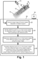
- a computer or other electronic data processing device 16 has a display 18 and an electronic processor and a non-transitory storage medium (details not shown) storing instructions readable and executable by the electronic processor to perform a positioning method 20 (diagrammatically indicated in FIGURE 1 ) including the operation 22 of receiving the range image acquired by the range camera 10 of the human subject 12 and a subject support 14 on which the human subject is disposed, and, using the range image, determining a reference point on or in the human subject in a frame of reference of the subject support.
- a positioning method 20 (diagrammatically indicated in FIGURE 1 ) including the operation 22 of receiving the range image acquired by the range camera 10 of the human subject 12 and a subject support 14 on which the human subject is disposed, and, using the range image, determining a reference point on or in the human subject in a frame of reference of the subject support.
- the non-transitory storage medium may, by way of non-limiting illustrative example, include a hard disk or other magnetic storage medium, an optical disk or other optical storage medium, a solid state drive, flash memory or other electronic storage medium, various combinations thereof, or so forth.
- the reference point determination includes the operation 24 of identifying a reference point on the human subject by detecting a hand or object (imaged) in the range image that is pointing to the reference point.
- the reference point on or in the human subject is determined in the reference frame of the subject support using the range image.
- the reference point on or in the human subject is translated from the reference frame of the subject support to a reference frame of the medical imaging device.
- the operation 28 is done using an a priori known fixed spatial relationship between the subject support docked with the medical imaging device. The operation 28 is described in further detail later herein with reference to FIGURE 5 .
- the range camera 10 is a camera that generates a range image.
- a range image comprises a two-dimensional (2D) image in which each pixel has a depth value.
- the range image captures three-dimensional (3D) information about the imaged subject.
- a range image acquired by the range camera 10 has pixel values corresponding to distances from the range camera 10.
- Range cameras may employ various technologies to generate the range (i.e. depth) value for each pixel, such as light coding technology employed in the range camera component of the Kinect TM multi-sensor device (available from Microsoft Corporation), sheet of light triangulation, time-of-flight depth coding, or so forth.
- some other suitable range cameras are available from Orbbec 3D Tech. Intl. Inc. and Intel Corporation (Intel ® RealSense TM Camera).
- Commercial range cameras typically operate in the infrared, although range cameras operating in other wavelength ranges are also available.
- the reference position can be located in 3D from the 3D information contained in the range image.
- the range image contains 3D information, this information is limited to the exterior surface of the imaging subject 12. In some embodiments, this is sufficient as it enables identifying a reference point on the visible exterior of the subject, thus providing capability comparable with existing laser projection positioning systems.
- the range image can be exploited in conjunction with anatomical modeling to provide additional information, which can have various uses such as identifying the reference point as a point inside the subject, and/or enabling simulation of the subject loading process to detect a potential subject-bore collision situation.
- a 3D generic human body model 30 is warped to generate a 3D human subject model 32 that is aligned with the range image of the human subject 12 disposed on the subject support 14.
- the warping is performed by skeletal tracking of a skeletal representation 34 of the human subject model 32.
- the human body is represented by a number of joints making up the skeletal representation 34 and representing body parts such as head, neck, shoulders, and arms.
- this is diagrammatically indicated by open circles in the 3D human subject model 32 each representing a joint indicated by a plus sign in the skeletal representation 34.
- Each joint is represented by its 3D coordinates in a body frame of reference F B of the human subject (the plus sign markers).
- the equivalent representation of joints are represented as markers in generic human subject model 30 (the open circle markers).
- the generic human subject model 30 acts as template model.
- the 3D coordinates (marker coordinates) are warped based on real-time 3D coordinates acquired from the range image to generate the 3D human subject model 32.
- the intermediate body parts are estimated and mapped on the adapted 3D human subject model 32.
- the estimated body parts may be classified as regions of interest based on predefined MRI scan protocols. Based the anatomical region for scan corresponding region of interest is highlighted to define the reference point.
- the region of interest representation on the 3D human subject model 32 is formed using per-pixel body part recognition using the range image.
- the per-pixel distribution may be computed using mean shift by evaluating each pixel separately.
- the per-pixel distribution is used to segment the region of interest in the resultant 3D human subject model 32.
- the region of interest can be distribution or same pixel value or combination of pixel values based on the region for scan.
- the 3D generic human body model 30 is not necessarily generic to all human bodies. For example, it is contemplated to have different 3D generic human body models for male and female, and/or for children (possibly of various ages) versus adults, and/or for different body mass index (BMI) values, and/or so forth. In this case, determining the reference point further includes selecting one of the 3D generic human body models for use in the warping based on a human body class input received by the computer 16 as part of the MRI examination setup process.
- the range image is preferably acquired in operation 22 before coil placement for precise patient model adaptation with appropriate patient position for mapping.
- the reference point may be generated in various ways.
- the reference point is placed at the center of the region of interest in the 3D human subject model 32.
- the region of interest may be identified by the technician pointing to it while the range image is acquired, or the region of interest may be determined automatically based on information entered during setup of the MRI examination, e.g. entry of the reason for examination.
- the reference point is typically the center of the field of view (FOV) for MRI scan acquisition.
- FOV field of view
- a user-defined reference point can be set manually.
- a rod 40 is used by the MRI technician to point to the reference point.
- the computer 16 analyzes the range image to detect the rod 40 is pointing to the head region, and automatically places a brain imaging reference point 42 at the center of the brain region of interest. This approach is semi-automated in that the computer 16 calculates the brain imaging reference point 42 as the center of the brain region of interest, so that the MRI technician need only direct the rod 40 to generally identify the head of the patient.
- the computer 16 generates a projection 44 of the rod into the (model of) the human head to locate the reference point 42.
- a representation such as that of FIGURE 3 may be displayed on the display 18 of the computer 16 and the user may operate a slider or other graphical user interface (GUI) dialog control to adjust the depth of the projection 44.
- GUI graphical user interface
- the reference point can be identified inside the human body; by contrast, laser projection patient positioning devices typically locate the reference point on the surface of the human body. Since MRI and other medical imaging techniques are imaging the interior of the human body, the ability to locate the reference point inside the human body provides better positioning of the region of interest at the isocenter of the MRI magnet (or, more generally, provides better positioning of the region of interest at the center of the examination region of the medical imaging device).
- the reference point on or in the human subject 12 is determined in the reference frame of the subject support 14.
- the reference features on the subject support 14 should be imaged by the range image, and accordingly may be dedicated features such as molded grooves or ridges (providing range variation) or features such as corners off the subject support.
- the overall spatial coordinates of patient table and patient model is extracted in this process.
- FIGURE 1 indicates the aforementioned body frame of reference F B of the human subject 12, and also a subject support frame of reference F S of the subject support 14.
- the two frames of reference are both Cartesian with x-, y-, and z-directions that are parallel in the two frames of reference F B , F S .
- the reference point in the body reference frame F B is given by the Cartesian coordinates (x B , y B , z B )
- the reference point in the subject support reference frame F S is given by the Cartesian coordinates (x S , ys, z S )
- the factors ⁇ x BS , ⁇ y BS , and ⁇ z BS are the translational shifts determined from the range image, and more particularly by the x-, y-, and z-directional distances between the body and subject support reference markers.
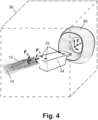
- the operation 28 translates the reference point from the frame of reference F S of the subject support to a frame of reference F D of a medical imaging device 50.
- the subject support 14 is designed to dock with the medical imaging device 50 with some defined spatial between the two components 14, 50 in the docked position.
- the subject support 14 includes mating features (not shown) that mate with mating features 52 of the medical imaging device 50 to dock the subject support 14 to the medical imaging device 50.
- the subject support 14 is a tabletop that has pegs, holes, or other mating features that mate with the mating features 52 comprising mating holes, pegs, or the like of a robotic patient loading couch 54 of the MRI imaging device 50.
- the subject support is a dockable couch or gurney, and the couch or gurney has wheels and a docking connector for connecting the couch or gurney to the MRI device.
- the patient positioning method 20 of FIGURE 1 can be performed entirely outside of the MRI examination room containing the MRI device 50.
- the MRI device 50 is typically located in a radio frequency shielded magnetic resonance imaging (MRI) examination room 56, so as to suppress radio frequency (RF) interference from outside reaching the MRI device 50 and so as to block the magnetic and RF and magnetic fields generated by the MRI device 50 from interfering with electronic equipment and devices located outside of the shielded MRI examination room 56.
- the disclosed approach leverages the subject support 14 and its frame of reference F S to provide a "bridge" for translating the reference point on the imaging subject 12 from the body reference frame F B to the imaging device reference frame F D .
- each of the operations 22, 24, 26, 28 can be performed outside of the shielded MRI examination room 56.
- This can increase patient throughput in an MRI laboratory as while one patient is being imaged in the shielded MRI examination room 56, the next patient can be prepared for examination including identifying the reference point in an adjacent room.
- this can be done using the range camera 10, without the need for using a laser projection system with its potential for introducing ocular discomfort.
- a range camera may additionally or alternatively be provided in the MRI examination room.
- the patient positioning method 20 is suitably performed in the MRI examination room.
- the patient positioning method 20 can be performed outside the MRI examination room and the result confirmed using the camera inside the MRI examination room, e.g. by repeating the patient modeling process of FIGURE 2 using a range image acquired using the range camera in the MRI examination room to correct for any changes in patient positioning that may have occurred as the patient is moved into the MRI examination room. If a range camera is located inside the MRI examination room, then it should be suitably shielded to control RF interference.
- the 3D coordinates of the reference point passed from the patient positioning process can also be used as an input for other examination setup actions, such as defining the slice thickness for the region of interest and different post-processing steps in MR image based application like diffusion weighted imaging.
- a graphical virtual 3D model of MRI device 50 along with a 3D model of the subject support 14 and the aforementioned 3D human subject model 32, is stored on the non-transitory storage medium of the computer 16 to enable graphical visualization of the entire patient loading process (and optionally the entire image acquisition process) on the display 18 of the computer 16.
- the 3D MRI device model represents the actual MRI device 50, and the adapted 3D human subject model 32 is placed over the 3D model of the subject support 14 to provide a visualization of the entire system.
- the reference point coordinates defined on the 3D human subject model 32 is translated into the 3D model of the MRI device 50.
- the coordinates of the reference point which are acquired using the range camer a 10 serve as reference between the simulation system and the actual setup.
- the simulation of the loading process can be performed to visualize the field of view of the scan and perform a pre-acquisition check.
- the 3D coordinates of the reference point are passed to the MRI device 50 which positions the subject support 14 automatically to the center of scanner bore or the field of view.
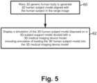
- FIGURE 5 depicts the loading simulation process, including operation 60 comprising the warping of the 3D generic human body model 30 to generate the 3D human subject model 32 as already described, e.g.
- an operation 62 comprising displaying a simulation of the 3D human subject model 32 disposed on a 3D subject support model (representing subject support 14 ) docked with a 3D medical imaging device model (representing the MRI device 50 ).
- the simulation includes simulation of loading the 3D human subject model 32 into the 3D medical imaging device model
- frame of reference transfers i.e. from the body reference frame F B to the subject support reference frame F S via Equation (1) followed by from the support reference frame F S to the MRI device reference frame F D via Equation (2), is merely an illustrative example, and other approaches can be employed.
- the use of body modeling as per FIGURE 2 can optionally be omitted, and the reference point directly defined from the range image in the frame of reference F S of the subject support 14. This can be done since the subject support 14 is imaged in the range image, so its coordinate system can be used directly.
- This approach makes it more difficult to define a reference point inside (rather than on an imaged surface of) the subject 12, but an approach such as the described projection 44 can be used, employing a "typical" depth of the brain center.
- This approach also omits the body frame of reference F B and the modeling of FIGURE 2 , and accordingly the dynamic loading simulation aspect described with reference to FIGURE 5 is not implementd.
- CT transmission computed tomography
- PET positron emission tomography
- SPECT single photon emission computed tomography
- hybrid medical imaging devices e.g., PET/CT
Landscapes
- Health & Medical Sciences (AREA)
- Engineering & Computer Science (AREA)
- Physics & Mathematics (AREA)
- Life Sciences & Earth Sciences (AREA)
- General Physics & Mathematics (AREA)
- Medical Informatics (AREA)
- General Health & Medical Sciences (AREA)
- Theoretical Computer Science (AREA)
- Surgery (AREA)
- Biophysics (AREA)
- Biomedical Technology (AREA)
- Heart & Thoracic Surgery (AREA)
- Molecular Biology (AREA)
- Pathology (AREA)
- Animal Behavior & Ethology (AREA)
- Public Health (AREA)
- Veterinary Medicine (AREA)
- Nuclear Medicine, Radiotherapy & Molecular Imaging (AREA)
- Computer Vision & Pattern Recognition (AREA)
- Radiology & Medical Imaging (AREA)
- High Energy & Nuclear Physics (AREA)
- Human Computer Interaction (AREA)
- Condensed Matter Physics & Semiconductors (AREA)
- Multimedia (AREA)
- Physiology (AREA)
- Dentistry (AREA)
- Oral & Maxillofacial Surgery (AREA)
- Quality & Reliability (AREA)
- Signal Processing (AREA)
- Optics & Photonics (AREA)
- Magnetic Resonance Imaging Apparatus (AREA)
Applications Claiming Priority (2)
| Application Number | Priority Date | Filing Date | Title |
|---|---|---|---|
| IN201641034779 | 2016-10-12 | ||
| PCT/EP2017/076137 WO2018069479A1 (en) | 2016-10-12 | 2017-10-12 | An intelligent model based patient positioning system for magnetic resonance imaging |
Publications (2)
| Publication Number | Publication Date |
|---|---|
| EP3525662A1 EP3525662A1 (en) | 2019-08-21 |
| EP3525662B1 true EP3525662B1 (en) | 2024-07-31 |
Family
ID=60245036
Family Applications (1)
| Application Number | Title | Priority Date | Filing Date |
|---|---|---|---|
| EP17793847.9A Active EP3525662B1 (en) | 2016-10-12 | 2017-10-12 | An intelligent model based patient positioning system |
Country Status (5)
| Country | Link |
|---|---|
| US (1) | US11647917B2 (enExample) |
| EP (1) | EP3525662B1 (enExample) |
| JP (1) | JP7080228B6 (enExample) |
| CN (1) | CN109862825B (enExample) |
| WO (1) | WO2018069479A1 (enExample) |
Families Citing this family (8)
| Publication number | Priority date | Publication date | Assignee | Title |
|---|---|---|---|---|
| EP3633622A1 (en) | 2018-10-02 | 2020-04-08 | Koninklijke Philips N.V. | Generation of pseudo radiographic images from optical images |
| EP3646794A1 (en) * | 2018-11-02 | 2020-05-06 | Koninklijke Philips N.V. | Positioning of a patient carrier |
| EP3998106B1 (en) * | 2018-12-17 | 2024-11-20 | Shanghai United Imaging Healthcare Co., Ltd. | Systems and methods for determining a region of interest of a subject |
| CN110286343B (zh) * | 2019-07-10 | 2021-06-25 | 苏州众志医疗科技有限公司 | 一种磁共振射频接收线圈和图像后处理方法 |
| JP7443965B2 (ja) * | 2020-07-13 | 2024-03-06 | オムロン株式会社 | 情報処理装置、補正方法、プログラム |
| CN112401919B (zh) * | 2020-11-17 | 2023-04-21 | 上海联影医疗科技股份有限公司 | 一种基于摆位模型的辅助摆位方法及系统 |
| US12308108B2 (en) * | 2021-08-20 | 2025-05-20 | GE Precision Healthcare LLC | Automatically detecting characteristics of a medical image series |
| EP4455704A1 (de) * | 2023-04-25 | 2024-10-30 | Siemens Healthineers AG | Verfahren zu einem bereitstellen eines kollisionsvermeidungsmodells für eine bewegung eines patiententischs in einem patientenaufnahmebereich einer magnetresonanzvorrichtung |
Family Cites Families (24)
| Publication number | Priority date | Publication date | Assignee | Title |
|---|---|---|---|---|
| US6405072B1 (en) * | 1991-01-28 | 2002-06-11 | Sherwood Services Ag | Apparatus and method for determining a location of an anatomical target with reference to a medical apparatus |
| JP2003310592A (ja) | 2002-04-22 | 2003-11-05 | Toshiba Corp | 遠隔x線撮像方法、遠隔x線撮像システム、医用画像診断装置のシミュレーション方法、情報処理サービス方法、及びモダリティシミュレータシステム |
| DE10346410A1 (de) | 2003-10-07 | 2005-05-04 | Martin Tank | Verfahren zur Bestimmung von patientenbezogenen Informationen zur Position und Orientierung von Schnittbildaufnahmen bei magnetresonanztomographischen Untersuchungen |
| JP2006288908A (ja) | 2005-04-14 | 2006-10-26 | Hitachi Medical Corp | 医用画像診断装置 |
| DE102005053488A1 (de) * | 2005-11-09 | 2007-05-16 | Siemens Ag | Bildgebungsvorrichtung und Therapieanlage mit einer solchen |
| US20070225588A1 (en) * | 2006-03-17 | 2007-09-27 | Michael Steckner | Automated Patient Localization in a Medical Imaging System |
| CN100536770C (zh) * | 2007-03-29 | 2009-09-09 | 新奥博为技术有限公司 | 一种磁共振图像引导下的手术系统及手术导航方法 |
| JP2011514828A (ja) | 2008-03-12 | 2011-05-12 | コーニンクレッカ フィリップス エレクトロニクス エヌ ヴィ | X線システムのためのモデルベース自己位置調整患者テーブル |
| EP2189945A1 (en) * | 2008-11-21 | 2010-05-26 | A&P ip B.V. | Method of and arrangement for linking image coordinates to coordinates of reference model |
| FR2970638B1 (fr) * | 2011-01-26 | 2014-03-07 | Inst Nat Rech Inf Automat | Procede et systeme d'aide au positionnement d'un outil medical sur la tete d'un sujet |
| KR20130057653A (ko) * | 2011-11-24 | 2013-06-03 | 삼성전자주식회사 | 의료영상기기 |
| CN103181764B (zh) * | 2011-12-30 | 2015-03-11 | 上海爱立峰医疗科技有限公司 | 磁共振扫描定位系统及指向性定位扫描方法 |
| US10925564B2 (en) * | 2012-04-20 | 2021-02-23 | Siemens Medical Solutions Usa, Inc. | Medical imaging system with range imaging-based control |
| GB2506903A (en) | 2012-10-12 | 2014-04-16 | Vision Rt Ltd | Positioning patient for radio-therapy using 3D models and reflective markers |
| US20150002419A1 (en) * | 2013-06-26 | 2015-01-01 | Microsoft Corporation | Recognizing interactions with hot zones |
| JP6433149B2 (ja) | 2013-07-30 | 2018-12-05 | キヤノン株式会社 | 姿勢推定装置、姿勢推定方法およびプログラム |
| US10493298B2 (en) | 2013-08-02 | 2019-12-03 | Varian Medical Systems, Inc. | Camera systems and methods for use in one or more areas in a medical facility |
| CN103431863B (zh) | 2013-09-03 | 2015-11-18 | 奥泰医疗系统有限责任公司 | 用于磁共振的定位方法 |
| EP3073926B1 (en) | 2013-11-27 | 2017-06-28 | Koninklijke Philips N.V. | Interventional x-ray system with automatic iso-centering |
| EP3113682A4 (en) | 2014-03-06 | 2017-03-29 | Virtual Reality Medical Applications, Inc. | Virtual reality medical application system |
| JP6262105B2 (ja) | 2014-09-04 | 2018-01-17 | 株式会社東芝 | 画像処理装置、画像処理システム、画像処理方法及びプログラム |
| DE102014218557B4 (de) * | 2014-09-16 | 2023-04-27 | Siemens Healthcare Gmbh | Benutzerschnittstelle und Verfahren zur automatisierten Positionierung eines Patiententisches relativ zu einer medizintechnischen Anlage |
| WO2016120073A1 (en) * | 2015-01-29 | 2016-08-04 | Koninklijke Philips N.V. | Camera system for automated measurement of patient biometric and physiological parameters for use in a medical imaging modality |
| US9886534B2 (en) * | 2016-02-03 | 2018-02-06 | Varian Medical Systems, Inc. | System and method for collision avoidance in medical systems |
-
2017
- 2017-10-12 JP JP2019519744A patent/JP7080228B6/ja active Active
- 2017-10-12 US US16/341,201 patent/US11647917B2/en active Active
- 2017-10-12 EP EP17793847.9A patent/EP3525662B1/en active Active
- 2017-10-12 WO PCT/EP2017/076137 patent/WO2018069479A1/en not_active Ceased
- 2017-10-12 CN CN201780063206.0A patent/CN109862825B/zh active Active
Also Published As
| Publication number | Publication date |
|---|---|
| CN109862825A (zh) | 2019-06-07 |
| EP3525662A1 (en) | 2019-08-21 |
| JP2019532728A (ja) | 2019-11-14 |
| CN109862825B (zh) | 2023-02-03 |
| US20200178839A1 (en) | 2020-06-11 |
| WO2018069479A1 (en) | 2018-04-19 |
| US11647917B2 (en) | 2023-05-16 |
| JP7080228B2 (ja) | 2022-06-03 |
| JP7080228B6 (ja) | 2022-06-23 |
Similar Documents
| Publication | Publication Date | Title |
|---|---|---|
| EP3525662B1 (en) | An intelligent model based patient positioning system | |
| CN113573641B (zh) | 使用二维图像投影的跟踪系统与图像的空间配准 | |
| EP3073926B1 (en) | Interventional x-ray system with automatic iso-centering | |
| US9990744B2 (en) | Image registration device, image registration method, and image registration program | |
| US10799119B2 (en) | Method and apparatus for provision of preparatory information for magnetic resonance imaging | |
| JP5486182B2 (ja) | 情報処理装置および情報処理方法 | |
| US20170032527A1 (en) | Method and system for head digitization and co-registration of medical imaging data | |
| US10786309B2 (en) | Radiation-free registration of an optical shape sensing system to an imaging system | |
| AU2015238800A1 (en) | Real-time simulation of fluoroscopic images | |
| US11989915B2 (en) | Intra-operative determination of a focal length of a camera for medical applications | |
| Frohwein et al. | PET attenuation correction for flexible MRI surface coils in hybrid PET/MRI using a 3D depth camera | |
| de Almeida et al. | A neuronavigation system using a mobile augmented reality solution | |
| CN112137621A (zh) | 医学成像测量期间的患者运动的确定 | |
| CN109907833A (zh) | 医学成像中的标记描绘 | |
| EP4128145B1 (en) | Combining angiographic information with fluoroscopic images | |
| Ahmadian et al. | An efficient method for estimating soft tissue deformation based on intraoperative stereo image features and point‐based registration | |
| Yano et al. | Accuracy verification of knife tip positioning with position and orientation estimation of the actual liver for liver surgery support system | |
| Hellwich et al. | Patient registration using photogrammetric surface reconstruction from smartphone imagery | |
| JP5808446B2 (ja) | 情報処理装置および情報処理方法 | |
| US20250022581A1 (en) | Item of Intervention Information in an Image Recording Region | |
| JP2024509590A (ja) | マルチステーションスキャンにおけるクリティカルステーションの自動検出 | |
| WO2025040243A1 (en) | Patient positioning using a surface model for medical imaging | |
| CN119924864A (zh) | 一种放射性射线成像的方法及设备 | |
| CN119270169A (zh) | 磁共振摄像装置及多通道接收线圈的自动通道选择方法 | |
| CN118234421A (zh) | 用于生成经引导经皮手术的不确定性图的方法和设备 |
Legal Events
| Date | Code | Title | Description |
|---|---|---|---|
| STAA | Information on the status of an ep patent application or granted ep patent |
Free format text: STATUS: UNKNOWN |
|
| STAA | Information on the status of an ep patent application or granted ep patent |
Free format text: STATUS: THE INTERNATIONAL PUBLICATION HAS BEEN MADE |
|
| PUAI | Public reference made under article 153(3) epc to a published international application that has entered the european phase |
Free format text: ORIGINAL CODE: 0009012 |
|
| STAA | Information on the status of an ep patent application or granted ep patent |
Free format text: STATUS: REQUEST FOR EXAMINATION WAS MADE |
|
| 17P | Request for examination filed |
Effective date: 20190513 |
|
| AK | Designated contracting states |
Kind code of ref document: A1 Designated state(s): AL AT BE BG CH CY CZ DE DK EE ES FI FR GB GR HR HU IE IS IT LI LT LU LV MC MK MT NL NO PL PT RO RS SE SI SK SM TR |
|
| AX | Request for extension of the european patent |
Extension state: BA ME |
|
| DAV | Request for validation of the european patent (deleted) | ||
| DAX | Request for extension of the european patent (deleted) | ||
| RAP1 | Party data changed (applicant data changed or rights of an application transferred) |
Owner name: KONINKLIJKE PHILIPS N.V. |
|
| STAA | Information on the status of an ep patent application or granted ep patent |
Free format text: STATUS: EXAMINATION IS IN PROGRESS |
|
| 17Q | First examination report despatched |
Effective date: 20220705 |
|
| GRAP | Despatch of communication of intention to grant a patent |
Free format text: ORIGINAL CODE: EPIDOSNIGR1 |
|
| STAA | Information on the status of an ep patent application or granted ep patent |
Free format text: STATUS: GRANT OF PATENT IS INTENDED |
|
| INTG | Intention to grant announced |
Effective date: 20240306 |
|
| GRAS | Grant fee paid |
Free format text: ORIGINAL CODE: EPIDOSNIGR3 |
|
| GRAA | (expected) grant |
Free format text: ORIGINAL CODE: 0009210 |
|
| STAA | Information on the status of an ep patent application or granted ep patent |
Free format text: STATUS: THE PATENT HAS BEEN GRANTED |
|
| AK | Designated contracting states |
Kind code of ref document: B1 Designated state(s): AL AT BE BG CH CY CZ DE DK EE ES FI FR GB GR HR HU IE IS IT LI LT LU LV MC MK MT NL NO PL PT RO RS SE SI SK SM TR |
|
| REG | Reference to a national code |
Ref country code: CH Ref legal event code: EP Ref country code: GB Ref legal event code: FG4D |
|
| REG | Reference to a national code |
Ref country code: DE Ref legal event code: R096 Ref document number: 602017083714 Country of ref document: DE |
|
| REG | Reference to a national code |
Ref country code: DE Ref legal event code: R084 Ref document number: 602017083714 Country of ref document: DE |
|
| REG | Reference to a national code |
Ref country code: IE Ref legal event code: FG4D |
|
| REG | Reference to a national code |
Ref country code: LT Ref legal event code: MG9D |
|
| REG | Reference to a national code |
Ref country code: NL Ref legal event code: MP Effective date: 20240731 |
|
| PG25 | Lapsed in a contracting state [announced via postgrant information from national office to epo] |
Ref country code: PT Free format text: LAPSE BECAUSE OF FAILURE TO SUBMIT A TRANSLATION OF THE DESCRIPTION OR TO PAY THE FEE WITHIN THE PRESCRIBED TIME-LIMIT Effective date: 20241202 |
|
| REG | Reference to a national code |
Ref country code: AT Ref legal event code: MK05 Ref document number: 1707674 Country of ref document: AT Kind code of ref document: T Effective date: 20240731 |
|
| PG25 | Lapsed in a contracting state [announced via postgrant information from national office to epo] |
Ref country code: PT Free format text: LAPSE BECAUSE OF FAILURE TO SUBMIT A TRANSLATION OF THE DESCRIPTION OR TO PAY THE FEE WITHIN THE PRESCRIBED TIME-LIMIT Effective date: 20241202 |
|
| PGFP | Annual fee paid to national office [announced via postgrant information from national office to epo] |
Ref country code: DE Payment date: 20241029 Year of fee payment: 8 |
|
| PG25 | Lapsed in a contracting state [announced via postgrant information from national office to epo] |
Ref country code: NO Free format text: LAPSE BECAUSE OF FAILURE TO SUBMIT A TRANSLATION OF THE DESCRIPTION OR TO PAY THE FEE WITHIN THE PRESCRIBED TIME-LIMIT Effective date: 20241031 |
|
| PG25 | Lapsed in a contracting state [announced via postgrant information from national office to epo] |
Ref country code: NL Free format text: LAPSE BECAUSE OF FAILURE TO SUBMIT A TRANSLATION OF THE DESCRIPTION OR TO PAY THE FEE WITHIN THE PRESCRIBED TIME-LIMIT Effective date: 20240731 Ref country code: PL Free format text: LAPSE BECAUSE OF FAILURE TO SUBMIT A TRANSLATION OF THE DESCRIPTION OR TO PAY THE FEE WITHIN THE PRESCRIBED TIME-LIMIT Effective date: 20240731 Ref country code: GR Free format text: LAPSE BECAUSE OF FAILURE TO SUBMIT A TRANSLATION OF THE DESCRIPTION OR TO PAY THE FEE WITHIN THE PRESCRIBED TIME-LIMIT Effective date: 20241101 Ref country code: FI Free format text: LAPSE BECAUSE OF FAILURE TO SUBMIT A TRANSLATION OF THE DESCRIPTION OR TO PAY THE FEE WITHIN THE PRESCRIBED TIME-LIMIT Effective date: 20240731 |
|
| PG25 | Lapsed in a contracting state [announced via postgrant information from national office to epo] |
Ref country code: BG Free format text: LAPSE BECAUSE OF FAILURE TO SUBMIT A TRANSLATION OF THE DESCRIPTION OR TO PAY THE FEE WITHIN THE PRESCRIBED TIME-LIMIT Effective date: 20240731 |
|
| PG25 | Lapsed in a contracting state [announced via postgrant information from national office to epo] |
Ref country code: LV Free format text: LAPSE BECAUSE OF FAILURE TO SUBMIT A TRANSLATION OF THE DESCRIPTION OR TO PAY THE FEE WITHIN THE PRESCRIBED TIME-LIMIT Effective date: 20240731 |
|
| PG25 | Lapsed in a contracting state [announced via postgrant information from national office to epo] |
Ref country code: IS Free format text: LAPSE BECAUSE OF FAILURE TO SUBMIT A TRANSLATION OF THE DESCRIPTION OR TO PAY THE FEE WITHIN THE PRESCRIBED TIME-LIMIT Effective date: 20241130 Ref country code: AT Free format text: LAPSE BECAUSE OF FAILURE TO SUBMIT A TRANSLATION OF THE DESCRIPTION OR TO PAY THE FEE WITHIN THE PRESCRIBED TIME-LIMIT Effective date: 20240731 |
|
| PGFP | Annual fee paid to national office [announced via postgrant information from national office to epo] |
Ref country code: FR Payment date: 20241025 Year of fee payment: 8 |
|
| PG25 | Lapsed in a contracting state [announced via postgrant information from national office to epo] |
Ref country code: HR Free format text: LAPSE BECAUSE OF FAILURE TO SUBMIT A TRANSLATION OF THE DESCRIPTION OR TO PAY THE FEE WITHIN THE PRESCRIBED TIME-LIMIT Effective date: 20240731 |
|
| PG25 | Lapsed in a contracting state [announced via postgrant information from national office to epo] |
Ref country code: RS Free format text: LAPSE BECAUSE OF FAILURE TO SUBMIT A TRANSLATION OF THE DESCRIPTION OR TO PAY THE FEE WITHIN THE PRESCRIBED TIME-LIMIT Effective date: 20241031 Ref country code: ES Free format text: LAPSE BECAUSE OF FAILURE TO SUBMIT A TRANSLATION OF THE DESCRIPTION OR TO PAY THE FEE WITHIN THE PRESCRIBED TIME-LIMIT Effective date: 20240731 |
|
| PG25 | Lapsed in a contracting state [announced via postgrant information from national office to epo] |
Ref country code: RS Free format text: LAPSE BECAUSE OF FAILURE TO SUBMIT A TRANSLATION OF THE DESCRIPTION OR TO PAY THE FEE WITHIN THE PRESCRIBED TIME-LIMIT Effective date: 20241031 Ref country code: PL Free format text: LAPSE BECAUSE OF FAILURE TO SUBMIT A TRANSLATION OF THE DESCRIPTION OR TO PAY THE FEE WITHIN THE PRESCRIBED TIME-LIMIT Effective date: 20240731 Ref country code: NO Free format text: LAPSE BECAUSE OF FAILURE TO SUBMIT A TRANSLATION OF THE DESCRIPTION OR TO PAY THE FEE WITHIN THE PRESCRIBED TIME-LIMIT Effective date: 20241031 Ref country code: NL Free format text: LAPSE BECAUSE OF FAILURE TO SUBMIT A TRANSLATION OF THE DESCRIPTION OR TO PAY THE FEE WITHIN THE PRESCRIBED TIME-LIMIT Effective date: 20240731 Ref country code: LV Free format text: LAPSE BECAUSE OF FAILURE TO SUBMIT A TRANSLATION OF THE DESCRIPTION OR TO PAY THE FEE WITHIN THE PRESCRIBED TIME-LIMIT Effective date: 20240731 Ref country code: IS Free format text: LAPSE BECAUSE OF FAILURE TO SUBMIT A TRANSLATION OF THE DESCRIPTION OR TO PAY THE FEE WITHIN THE PRESCRIBED TIME-LIMIT Effective date: 20241130 Ref country code: HR Free format text: LAPSE BECAUSE OF FAILURE TO SUBMIT A TRANSLATION OF THE DESCRIPTION OR TO PAY THE FEE WITHIN THE PRESCRIBED TIME-LIMIT Effective date: 20240731 Ref country code: GR Free format text: LAPSE BECAUSE OF FAILURE TO SUBMIT A TRANSLATION OF THE DESCRIPTION OR TO PAY THE FEE WITHIN THE PRESCRIBED TIME-LIMIT Effective date: 20241101 Ref country code: FI Free format text: LAPSE BECAUSE OF FAILURE TO SUBMIT A TRANSLATION OF THE DESCRIPTION OR TO PAY THE FEE WITHIN THE PRESCRIBED TIME-LIMIT Effective date: 20240731 Ref country code: ES Free format text: LAPSE BECAUSE OF FAILURE TO SUBMIT A TRANSLATION OF THE DESCRIPTION OR TO PAY THE FEE WITHIN THE PRESCRIBED TIME-LIMIT Effective date: 20240731 Ref country code: BG Free format text: LAPSE BECAUSE OF FAILURE TO SUBMIT A TRANSLATION OF THE DESCRIPTION OR TO PAY THE FEE WITHIN THE PRESCRIBED TIME-LIMIT Effective date: 20240731 Ref country code: AT Free format text: LAPSE BECAUSE OF FAILURE TO SUBMIT A TRANSLATION OF THE DESCRIPTION OR TO PAY THE FEE WITHIN THE PRESCRIBED TIME-LIMIT Effective date: 20240731 |
|
| PG25 | Lapsed in a contracting state [announced via postgrant information from national office to epo] |
Ref country code: RO Free format text: LAPSE BECAUSE OF FAILURE TO SUBMIT A TRANSLATION OF THE DESCRIPTION OR TO PAY THE FEE WITHIN THE PRESCRIBED TIME-LIMIT Effective date: 20240731 Ref country code: DK Free format text: LAPSE BECAUSE OF FAILURE TO SUBMIT A TRANSLATION OF THE DESCRIPTION OR TO PAY THE FEE WITHIN THE PRESCRIBED TIME-LIMIT Effective date: 20240731 Ref country code: SM Free format text: LAPSE BECAUSE OF FAILURE TO SUBMIT A TRANSLATION OF THE DESCRIPTION OR TO PAY THE FEE WITHIN THE PRESCRIBED TIME-LIMIT Effective date: 20240731 |
|
| PG25 | Lapsed in a contracting state [announced via postgrant information from national office to epo] |
Ref country code: EE Free format text: LAPSE BECAUSE OF FAILURE TO SUBMIT A TRANSLATION OF THE DESCRIPTION OR TO PAY THE FEE WITHIN THE PRESCRIBED TIME-LIMIT Effective date: 20240731 |
|
| PG25 | Lapsed in a contracting state [announced via postgrant information from national office to epo] |
Ref country code: CZ Free format text: LAPSE BECAUSE OF FAILURE TO SUBMIT A TRANSLATION OF THE DESCRIPTION OR TO PAY THE FEE WITHIN THE PRESCRIBED TIME-LIMIT Effective date: 20240731 |
|
| PG25 | Lapsed in a contracting state [announced via postgrant information from national office to epo] |
Ref country code: IT Free format text: LAPSE BECAUSE OF FAILURE TO SUBMIT A TRANSLATION OF THE DESCRIPTION OR TO PAY THE FEE WITHIN THE PRESCRIBED TIME-LIMIT Effective date: 20240731 Ref country code: SK Free format text: LAPSE BECAUSE OF FAILURE TO SUBMIT A TRANSLATION OF THE DESCRIPTION OR TO PAY THE FEE WITHIN THE PRESCRIBED TIME-LIMIT Effective date: 20240731 |
|
| REG | Reference to a national code |
Ref country code: DE Ref legal event code: R097 Ref document number: 602017083714 Country of ref document: DE |
|
| REG | Reference to a national code |
Ref country code: CH Ref legal event code: PL |
|
| PLBE | No opposition filed within time limit |
Free format text: ORIGINAL CODE: 0009261 |
|
| STAA | Information on the status of an ep patent application or granted ep patent |
Free format text: STATUS: NO OPPOSITION FILED WITHIN TIME LIMIT |
|
| GBPC | Gb: european patent ceased through non-payment of renewal fee |
Effective date: 20241031 |
|
| PG25 | Lapsed in a contracting state [announced via postgrant information from national office to epo] |
Ref country code: MC Free format text: LAPSE BECAUSE OF FAILURE TO SUBMIT A TRANSLATION OF THE DESCRIPTION OR TO PAY THE FEE WITHIN THE PRESCRIBED TIME-LIMIT Effective date: 20240731 |
|
| 26N | No opposition filed |
Effective date: 20250501 |
|
| PG25 | Lapsed in a contracting state [announced via postgrant information from national office to epo] |
Ref country code: GB Free format text: LAPSE BECAUSE OF NON-PAYMENT OF DUE FEES Effective date: 20241031 |
|
| PG25 | Lapsed in a contracting state [announced via postgrant information from national office to epo] |
Ref country code: LU Free format text: LAPSE BECAUSE OF NON-PAYMENT OF DUE FEES Effective date: 20241012 Ref country code: BE Free format text: LAPSE BECAUSE OF NON-PAYMENT OF DUE FEES Effective date: 20241031 |
|
| PG25 | Lapsed in a contracting state [announced via postgrant information from national office to epo] |
Ref country code: CH Free format text: LAPSE BECAUSE OF NON-PAYMENT OF DUE FEES Effective date: 20241031 |
|
| REG | Reference to a national code |
Ref country code: BE Ref legal event code: MM Effective date: 20241031 |
|
| PG25 | Lapsed in a contracting state [announced via postgrant information from national office to epo] |
Ref country code: SE Free format text: LAPSE BECAUSE OF FAILURE TO SUBMIT A TRANSLATION OF THE DESCRIPTION OR TO PAY THE FEE WITHIN THE PRESCRIBED TIME-LIMIT Effective date: 20240731 |
|
| PG25 | Lapsed in a contracting state [announced via postgrant information from national office to epo] |
Ref country code: IE Free format text: LAPSE BECAUSE OF NON-PAYMENT OF DUE FEES Effective date: 20241012 |