EP3525280B1 - Fluidverteilermodul für ein modulares temperiersystem und temperiersystem - Google Patents
Fluidverteilermodul für ein modulares temperiersystem und temperiersystem Download PDFInfo
- Publication number
- EP3525280B1 EP3525280B1 EP19156284.2A EP19156284A EP3525280B1 EP 3525280 B1 EP3525280 B1 EP 3525280B1 EP 19156284 A EP19156284 A EP 19156284A EP 3525280 B1 EP3525280 B1 EP 3525280B1
- Authority
- EP
- European Patent Office
- Prior art keywords
- section
- module
- interface
- fluid distributor
- fluid
- Prior art date
- Legal status (The legal status is an assumption and is not a legal conclusion. Google has not performed a legal analysis and makes no representation as to the accuracy of the status listed.)
- Active
Links
Images


Classifications
-
- H—ELECTRICITY
- H01—ELECTRIC ELEMENTS
- H01M—PROCESSES OR MEANS, e.g. BATTERIES, FOR THE DIRECT CONVERSION OF CHEMICAL ENERGY INTO ELECTRICAL ENERGY
- H01M10/00—Secondary cells; Manufacture thereof
- H01M10/60—Heating or cooling; Temperature control
- H01M10/61—Types of temperature control
- H01M10/613—Cooling or keeping cold
-
- H—ELECTRICITY
- H01—ELECTRIC ELEMENTS
- H01M—PROCESSES OR MEANS, e.g. BATTERIES, FOR THE DIRECT CONVERSION OF CHEMICAL ENERGY INTO ELECTRICAL ENERGY
- H01M10/00—Secondary cells; Manufacture thereof
- H01M10/60—Heating or cooling; Temperature control
- H01M10/62—Heating or cooling; Temperature control specially adapted for specific applications
- H01M10/625—Vehicles
-
- H—ELECTRICITY
- H01—ELECTRIC ELEMENTS
- H01M—PROCESSES OR MEANS, e.g. BATTERIES, FOR THE DIRECT CONVERSION OF CHEMICAL ENERGY INTO ELECTRICAL ENERGY
- H01M10/00—Secondary cells; Manufacture thereof
- H01M10/60—Heating or cooling; Temperature control
- H01M10/65—Means for temperature control structurally associated with the cells
- H01M10/655—Solid structures for heat exchange or heat conduction
- H01M10/6556—Solid parts with flow channel passages or pipes for heat exchange
-
- H—ELECTRICITY
- H01—ELECTRIC ELEMENTS
- H01M—PROCESSES OR MEANS, e.g. BATTERIES, FOR THE DIRECT CONVERSION OF CHEMICAL ENERGY INTO ELECTRICAL ENERGY
- H01M10/00—Secondary cells; Manufacture thereof
- H01M10/60—Heating or cooling; Temperature control
- H01M10/65—Means for temperature control structurally associated with the cells
- H01M10/656—Means for temperature control structurally associated with the cells characterised by the type of heat-exchange fluid
- H01M10/6567—Liquids
- H01M10/6568—Liquids characterised by flow circuits, e.g. loops, located externally to the cells or cell casings
-
- H—ELECTRICITY
- H01—ELECTRIC ELEMENTS
- H01M—PROCESSES OR MEANS, e.g. BATTERIES, FOR THE DIRECT CONVERSION OF CHEMICAL ENERGY INTO ELECTRICAL ENERGY
- H01M2220/00—Batteries for particular applications
- H01M2220/20—Batteries in motive systems, e.g. vehicle, ship, plane
-
- Y—GENERAL TAGGING OF NEW TECHNOLOGICAL DEVELOPMENTS; GENERAL TAGGING OF CROSS-SECTIONAL TECHNOLOGIES SPANNING OVER SEVERAL SECTIONS OF THE IPC; TECHNICAL SUBJECTS COVERED BY FORMER USPC CROSS-REFERENCE ART COLLECTIONS [XRACs] AND DIGESTS
- Y02—TECHNOLOGIES OR APPLICATIONS FOR MITIGATION OR ADAPTATION AGAINST CLIMATE CHANGE
- Y02E—REDUCTION OF GREENHOUSE GAS [GHG] EMISSIONS, RELATED TO ENERGY GENERATION, TRANSMISSION OR DISTRIBUTION
- Y02E60/00—Enabling technologies; Technologies with a potential or indirect contribution to GHG emissions mitigation
- Y02E60/10—Energy storage using batteries
Definitions
- the present invention relates to a fluid distribution module for a modular temperature control system of an energy store, in particular a cooling system for vehicle batteries, with at least one first module interface for connection to at least one further fluid distribution module, at least one first distribution interface for connection to at least one cooling element and at least one fluid channel as well as a temperature control system.
- Temperature control systems known from the prior art have through-flow cooling plates, in particular aluminum cooling plates, on which the battery cells are positioned. The size and number of cooling plates depends on the geometry and number of battery cells.
- the cooling plates are typically individually flowed through with a temperature control medium, for example a mixture of water and glycol.
- a temperature control medium for example a mixture of water and glycol.
- the inflow and outflows of the cooling plates are each fed into a collecting line as a flow or return.
- the temperature control system In addition to distributing the temperature control medium to the individual cooling plates, the temperature control system, in particular the fluid distribution modules arranged in it, must compensate for the tolerances between the cooling plates and between the connections on a cooling plate and enable simple installation and removal.
- Temperature control systems known from the prior art are usually assembled from a large number of individual connectors and pipe sections. For example, assembly takes place by expanding or plugging together.
- WO 2017/095172 A1 discloses a cooling system for batteries.
- the cooling system comprises a plurality of pipelines which are connected to form a fluid system.
- the cooling system comprises at least two different materials for the pipelines.
- the straight pipe sections are made of a harder plastic.
- the curved pipe sections are made of a flexible rubber with high elasticity. The straight and curved elements are joined together by thermal shrinkage.
- EP 2 980 882 A1 discloses a frame for electrochemical cells with an integrated cooling channel. Plug-in pieces are arranged in the cooling channel in order to establish a connection.
- the frame and the plug-in piece can be made of the same or different materials.
- the connecting element comprises a base body, a connecting piece and two sealing elements, the sealing elements being materially connected to the connecting piece.
- EP 3 188 303 A1 discloses a cooling device disposed between a plurality of battery cells for an electric vehicle.
- the cooling device comprises one or more fluid lines which are arranged in a meandering shape between the individual battery cells.
- molded bodies are arranged on the fluid lines which adapt to the contour of the battery cells.
- the temperature control systems known from the prior art have the disadvantage that extensive assembly work is required and that the presence of a large number of connection points increases the risk of leakage.
- the present invention is therefore based on the object of specifying a fluid distribution module for a modular temperature control system and a temperature control system in which the assembly effort is reduced and in which the number of connection points is reduced.
- a first section of the fluid distribution module is formed from a first material and at least one second section is formed from a second material, in particular different from the first material that the second section at least partially has a lower rigidity than the first section, and that the first section and the second section are integrally formed on one another
- the fluid distribution module is a component for producing a fluid-conducting temperature control system for an energy store, preferably a fluid-conducting cooling system for vehicle batteries, in particular for conducting a pressurized fluid.
- the fluid distribution module has at least one first module interface which is designed and set up to connect the fluid distribution module to at least one further fluid distribution module, in particular to connect it fluidically.
- a plurality of interconnected fluid distribution modules form, for example, a flow or return of a temperature control system.
- a plurality of fluid distribution modules are designed and arranged for a serial flow through cooling elements.
- the module interface is designed, for example, as a plug connector, snap-in connector, clamp connector, bayonet lock or as another detachable or non-detachable connector.
- the first module interface is as formed to be plugged in or receiving part of a connector.
- the module interface enables a sealing connection to be established between two fluid distribution modules.
- the fluid distribution module has at least one first distribution interface which is designed and configured to connect the fluid distribution module to at least one cooling element, in particular at least one cooling plate.
- the distributor interface is designed, for example, as a plug connector, coupling, snap-in connector, clamp connector, bayonet lock or other detachable or non-detachable connector.
- the distributor interface is preferably arranged at an angle of 90 ° to the module interface.
- the fluid distribution module also has at least one fluid channel, which extends in particular between the module interface and the distribution interface.
- the fluid distribution module is characterized in that at least a first section of the fluid distribution module is formed from a first material and at least one second section is formed from a second material, in particular different from the first material, the second section having a lower rigidity than the first section .
- Rigidity is understood to mean the resistance of the first and second sections to elastic deformation by a force or a moment.
- the lower rigidity is achieved through the choice of material and / or the geometric design of the first section and / or the second section.
- the second material is softer, that is to say has a lower hardness, and / or has a lower modulus of elasticity than the first material.
- the second material or the second section has a lower resistance to elastic deformation than the first material or the first section.
- the second section or the second material is preferably more stretchable, bendable and / or compressible than the first material or the first section.
- the lower rigidity of the second section is preferably achieved exclusively through the choice of material, that is to say in that the second material is softer than the first material.
- the first section and / or the second section preferably delimit at least part of the fluid channel.
- the first section and the second section are molded onto one another, in particular molded onto one another during manufacture.
- "Shaping" here is to be understood as the production of a material connection which is formed when the first and / or the second section is produced.
- the first section is molded onto the second or the second segment onto the first, or both are molded onto one another at the same time during manufacture.
- the fluid distribution module is manufactured as a multicomponent part using a multicomponent manufacturing process, for example multicomponent injection molding or an additive manufacturing process, e.g. B. 3D printing.
- the fluid distribution module with the first section and the second section is produced in one piece from two different materials.
- a fourth or fifth section is formed, the fourth or fifth section or the material also having a lower rigidity than in the first section.
- the fluid distribution module thus has a plurality of flexible sections that allow easy deformation during assembly.
- the second section is less rigid, assembly is simplified and tolerances can be compensated for by elastic deformation of the second section. During assembly, the second section can be temporarily deformed in a simple manner in order to bring the fluid distribution module into its installation situation. Furthermore, the second section can be used to compensate for pressure pulsations in the temperature control system and a possible increase in the volume of the fluid.
- first section and the second section are molded onto one another increases the number of connection interfaces and thus the risk of leakage reduced.
- purity and quality requirements are met in a simple manner, since no post-processing is required. Post-processing can therefore be dispensed with in particular because only a one-piece component is present after production.
- a second distributor interface is present for connection to a cooling element.
- the flow through a connected cooling element can be increased through the second distributor interface.
- the second distributor interface is arranged, for example, parallel to the first distributor interface.
- first distributor interface and the second distributor interface are formed on the first section.
- first section serves to connect to a cooling element
- second section and, if applicable, the third section only serve to connect to a further fluid distribution module or to increase flexibility.
- first distributor interface and the second distributor interface are formed in one piece with the first section and, in particular, are formed from the first material.
- the module interface also ensures that at least two fluid distribution modules can be easily joined together, as a result of which a fluid can flow through two cooling elements arranged next to one another.
- the modular structure also enables temperature control systems of various sizes to be implemented.
- a second module interface is present for connection to a further fluid distribution module, in particular that the second module interface is formed on the second section or on a third section.
- the second module interface is designed in such a way that a connection to a further fluid distribution module can be established.
- the second module interface is a plug connector or a hose-shaped connection piece educated.
- the second module interface is preferably designed to correspond to the first module interface.
- the first module interface is preferably designed as a receiving part of a connector and the second module interface is designed as a part of a connector to be inserted.
- Two fluid distribution modules can thus be easily connected to one another in a sealing manner by plugging them together by means of the first and the second module interface.
- the first module interface and the second module interface are arranged in sections that are made from the first material.
- the first module interface and the second module interface are preferably arranged on a common longitudinal axis of the fluid distribution module.
- a further embodiment of the fluid distribution module provides that the fluid channel has a constant cross section at least in the course between the first module interface and the second module interface.
- the fluid channel runs along the longitudinal axis of the fluid distribution module.
- the first distributor interface is preferably connected in terms of fluid technology via a side arm of the fluid channel extending from the fluid channel with the constant cross section.
- a third section is formed and that the third section, in particular, is molded onto the second section. It is preferred that the second section is arranged between the first section and the third section, in particular it is provided that the third section is formed from the first material.
- the first section and the third section are preferably formed from the same material. The fact that the second section is formed between the first section and the third section ensures increased flexibility and mobility in the second section, which simplify assembly.
- the first section, the second section and the third section are each molded onto one another so that they are formed in one piece, in particular are produced together. This further reduces the number of connection points required for a temperature control system.
- At least one section of the first distributor interface and / or the second distributor interface is formed from the second material.
- the section of the first or second distributor interface formed from the second material is preferably molded onto the remaining sections of the respective distributor interface, so that they are formed in one piece.
- the assembly of the fluid distribution module is simplified by the presence of a section made of a second material with a lower rigidity than the first material.
- the second distributor interface is preferably designed identically to the first distributor interface.
- the length of the second section corresponds to at least 5% of the total length of the fluid distribution module, in particular between the outer ends of the first and second module interface, preferably between 5% and 35% of the total length. Because of this minimum length, it can be ensured that the second section has sufficient flexibility or deflectability to simplify assembly. In this context, according to a further embodiment, it is also advantageous if the second section has a length between 15 mm and 100 mm.
- the minimum length of the second Section corresponds to at least the minimum inner diameter of the fluid channel between the first module interface and the second module interface.
- the length of the second section consequently corresponds at least to the smallest diameter of the fluid channel in the course between the first and second module interfaces. This ensures that an advantageous assembly can be realized.
- the fluid distributor module is developed in that the first distributor interface and / or the second distributor interface have an assembly offset, and that the length of the second section corresponds approximately to twice the value of the assembly offset.
- the assembly offset is the path that the first distributor interface and / or the second distributor interface takes when being pushed or pushed into or onto a cooling element in order to be fluidically connected. This path corresponds to the assembly offset.
- the assembly offset is the plug-in path of a connector. Because the length of the second section corresponds approximately to twice the value of the assembly offset, it can be ensured that a plurality of fluid distribution modules can be easily assembled next to one another and one after the other.
- the assembly offset is between 15 mm and 25 mm, so that the preferred length of the second section is between 30 mm and 50 mm, advantageously 40 mm.
- the second section has a plurality of, in particular radially circumferential, elevations, preferably ribs or waves, on the outside and / or inside, in particular that the second section has its inner surface forming the fluid channel is smooth.
- the elevations formed on the outside and / or the inside, in particular ribs or waves, particularly preferably evenly distributed ribs or waves, locally strengthen the wall thickness of the second section, thereby increasing its compressive strength.
- the The spacing of the elevations from one another reliably ensures bendability of the second section.
- the second section is designed, for example, as a corrugated pipe with a smooth inner surface.
- the smooth inner surface prevents turbulence or adverse effects on the flow.
- the inside diameter is constant at least in the second section.
- easy removal from the mold during manufacture by means of injection molding can be guaranteed.
- the height of the elevations based on the wall thickness in areas without an elevation, preferably corresponds approximately to the wall thickness, so that the second section in the area of the elevations has twice the wall thickness.
- the elevations in the form of waves have different radii for wave crests and wave troughs, in particular that the distance between two wave crests is between 3 mm and 10 mm.
- the wall thickness in the second section between two elevations corresponds to between 5% and 20%, in particular about 7%, of the inner diameter of the fluid channel in the second section, in particular of the fluid channel between the first module interface and the second Module interface. This minimum wall thickness ensures sufficient compressive strength in the second section.
- the elevations, in particular on the inside, in the form of waves have different flank inclinations, in particular with respect to a longitudinal axis L, on adjacent flanks.
- a wave profile with different angles of the flanks is provided.
- the flank slopes extend over the entire Circumference, in particular the flank inclinations are constant over the respective circumference.
- the flanks inclined away from one end of the second section are preferably less inclined than the flanks facing or opposite the end.
- steeper flanks have an angle ⁇ 2 between 40 ° and 75 °, preferably 50 °, and flatter flanks an angle ⁇ 1 between 20 ° and 40 °, preferably 30 °, in particular to a longitudinal axis L.
- the adjacent flanks are generally inclined opposite to one another, but they have a different angle in terms of amount - a different inclination.
- flanks are curved and have a flank radius.
- the flanks with a larger radius correspond to the flatter flanks and the flanks with a smaller radius correspond to the steeper flanks.
- a smaller flank radius is followed by a larger flank radius and vice versa.
- the flatter flanks or larger flank radii ensure easy removal from the mold during manufacture along the flatter flanks or flanks with a larger flank radius, while the steeper flanks or smaller flank radii ensure increased flexibility of the second section.
- flanks are provided in the course of the second section with the same flank inclination or the same flank radius on opposite flanks.
- the flanks with the different flank inclinations are arranged in such a way that, starting from each end side, a steeper flank is initially arranged.
- a flatter flank is initially arranged. Starting from the two end sides, the respective flatter flanks or the steeper flanks are at the same angle, but inclined in opposite directions for each end side. This is followed by a steeper flank on a flatter flank or vice versa.
- two oppositely inclined flatter flanks meet. At this point, demolding takes place in opposite directions during production, so that demolding can advantageously take place along the flatter flanks.
- the flatter flanks are inclined or arranged in the demolding direction.
- the elevations with the flatter and steeper flanks or larger and smaller flank radii are preferably arranged at least on the inside. If the wall thickness of the second section is constant, these are also arranged on the outside.
- the compressive strength in the second section can be increased in particular in that the second section has a wall thickness that varies at least in sections, in particular in the region of the wave troughs, preferably has a wall thickness that is convex in the direction of its central region. Consequently, the minimum wall thickness varies in the area of the wave troughs such that the minimum wall thickness is greatest in the middle of the second section and decreases in the direction of the two ends. Furthermore, it is provided that the wall thickness of the second section increases, starting from the same wall thickness at the ends, in the direction of the center. As an alternative or in addition to this, it is provided that the inner diameter decreases starting from the two ends in the direction of the center. As a result, good internal pressure resistance can be ensured with, at the same time, good demoldability of an inner core.
- the second section has an essentially constant wall thickness.
- the wall thickness is preferably between 0.5 mm and 2 mm, in particular 1 mm.
- the second section has a convex wall thickness in cross section and / or that the inner wall is curved inward in the unpressurized state. If the temperature control system is then pressurized, the second section is arched outward by the applied pressure in such a way that that in the pressurized operating state a constant diameter is formed in the second section.
- the assembly of the fluid distribution module can in particular be further simplified in that the second material has a greater elasticity and / or less hardness than the first material.
- the fluid distribution module in the second section can be deformed in a simple manner and has a lower rigidity, as a result of which assembly on the cooling elements is simplified.
- the first material is made of polypropylene (PP), preferably with a proportion of up to 50% glass fibers, and / or the second material is a thermoplastic elastomer (TPE), preferably with a hardness Shore A in the range between 40 and 95, particularly preferably 60 and 90.
- PP polypropylene
- TPE thermoplastic elastomer
- the first and third sections are preferably made of polypropylene (PP), since with PP compared to polyamide (PA) the water absorption is significantly lower and thus the mechanical long-term properties are better. Furthermore, compared to PA, PP has a significantly lower swelling in water / glycol, which reduces the stresses in the operating state. When drying the system (e.g. in the event of service or longer shutdown times), the risk of possible stress cracks as a result of re-drying is excluded. Depending on the required strength, the first section and / or the third section is reinforced with a proportion of glass fiber (up to 50%) as required.
- the second section is preferably made from a thermoplastic elastomer (TPE) which has a material or chemical connection to the first or third section.
- TPE thermoplastic elastomer
- a TPE with a low compression set or high creep resistance is used in order to minimize the expansion of the compensation element under internal pressure loads.
- the material can be adapted to the application-specific via the Shore hardness of the TPE Pressure requirements of the temperature control medium in the temperature control system can be adjusted. This choice of material ensures that the fluid distribution module has high compressive strength and, at the same time, material properties that are easy to assemble.
- the second material is a thermoplastic polyolefin (TPO) or a thermoplastic polyolefin vulcanizate (TPV) or the second section has such a material.
- the second section is preferably made from a thermoplastic polyolefin (TPO) or a thermoplastic polyolefin vulcanizate (TPV).
- TPO thermoplastic polyolefin
- TPV thermoplastic polyolefin vulcanizate
- the second section has a Shore hardness greater than or equal to 35D, preferably 40D.
- the second material is jet-crosslinked.
- the second material or the second section has been subjected to at least one beam crosslinking.
- beam crosslinking for example, high-energy beta or gamma rays trigger chemical reactions in the plastic and lead to crosslinking of the molecules. This has the advantage that good internal pressure resistance is achieved with good long-term creep resistance and temperature resistance at the same time.
- the first material is polyamide 6.10 (PA 6.10) or polyamide 12 (PA 12) and / or the second material is a thermoplastic elastomer based on urethane (TPU), preferably with a glass fiber filling, particularly preferably with a Shore D hardness greater than or equal to 50.
- PA 6.10 polyamide 6.10
- PA 12 polyamide 12
- TPU thermoplastic elastomer based on urethane
- first section - as described above - to be formed from polypropylene and the second section to be formed from a thermoplastic elastomer based on urethane.
- thermoplastic elastomer based on urethane there is also a combination of polyamide, for example PA 6.10 or PA 12, in the first section and one thermoplastic elastomer provided in the second section.
- polypropylene with a thermoplastic elastomer based on urethane an - at least local - plasma activation of the polypropylene is carried out.
- TPU has very good long-term strength and, on the other hand, it can be optimized with regard to internal pressure resistance through glass fiber reinforcements.
- TPU as a material requires PA as a material in the first section in order to achieve a robust connection.
- PA 6.10 or PA12 is used, as these polyamides have a significantly lower water absorption compared to PA6 or PA6.6 types.
- PA6.10 has better mechanical properties and a higher temperature resistance. This choice of material also ensures good material properties with ease of installation at the same time.
- the stability of the fluid distribution module and the connection between the sections can be increased in particular by increasing the area in a contact area between the first section and the second section and / or between the second section and the third section, in particular compared to a circular cylindrical area , preferably by waves and projections and / or recesses.
- the sections are each molded onto one another, so that the enlargement of the contact area leads to a larger area for an integral connection.
- a tongue and groove geometry preferably with at least one groove and at least one tongue, is formed in a contact area between the first section and the second section and / or the second section and the third section.
- An additional form fit can be generated by a tongue and groove geometry, which has a positive effect on the stability of the fluid distribution module.
- At least one holding frame is formed, in particular that the base body has at least one holding frame.
- the holding frame preferably extends on the side opposite the distributor interfaces.
- the holding frame is designed, for example, as a bracket and has at least one access opening.
- At least one seal is formed on the first module interface and / or on the second module interface and / or on the first distributor interface and / or on the second distributor interface.
- the seal is preferably molded on during manufacture so that the fluid distribution module can be used immediately. Because the seal is molded on, it is already advantageously materially connected to the respective interface, which ensures reliable tightness.
- At least one fluid distribution module according to the invention is produced from at least two components, for the fluidic connection of cooling elements on a vehicle battery for temperature control purposes.
- the object mentioned at the beginning is also achieved with a cooling system, in particular for vehicle batteries, with at least one cooling plate and at least one fluid distribution module configured according to the invention.
- At least two fluid distribution modules are preferably connected to one another by means of the module interfaces, in particular at least one fluid distribution module being closed with an end cap on the second module interface.
- the end of the entire fluid channel is defined by the end cap, so that a flow only takes place through the cooling element arranged on this fluid distributor module, namely through the distributor interfaces.
- the end cap is designed, for example, as a separate component or in one piece with the third section. In the case of a one-piece configuration, the third section is closed during manufacture.
- Fig. 1 shows a fluid distribution module 1 for a modular temperature control system of an energy store, in particular for a cooling system for a vehicle battery - not shown in detail.
- the fluid distribution module 1 has at least one first module interface 2 for connecting the fluid distribution module 1 to at least one further fluid distribution module 1 - see for example Fig. 4 .
- the first module interface 2 is designed here as a receiving part of a plug connector.
- the fluid distribution module 1 also has at least one first distribution interface 3 for connection to a - for example in Fig. 4 - cooling element 20 and at least one fluid channel 4.
- the first distributor interface 3 is designed as a plug-in part of a connector.
- a first section 5 of the fluid distribution module 1 is formed from a first material, here polypropylene, while a second section 6 is formed from a second material different from the first material, here a thermoplastic elastomer.
- the second section 6 has a lower rigidity than the first section 5, so that the second section 6 can be deformed more easily than the first section 5.
- the second section 6 can be deformed during assembly, which simplifies assembly .
- the fluid distribution module 1 also has a second module interface 7, which is designed as a part of a connector that can be plugged into a receiving part of a connector - according to the first module interface 2.
- the second module interface 7 is formed on a third section 8, which is molded onto the second section 6, identically to the first section 5.
- the first section 5, the second section 6 and the third section 8 are consequently formed in one piece.
- the third section 8 is formed from the first material, so that the second section 6 due to its lower rigidity represents a flexible connecting link between the first section 5 and the third section 8.
- the length of the second section 6, in particular along the longitudinal axis L corresponds to about 30% of the total length of the fluid distribution module 1.
- the first section 5, the second section 6 and the third section 8 delimit the fluid channel 4 between the first module interface 2 and the second module interface 7th
- the fluid channel 4 has a constant cross section in the course between the first module interface 2 and the second module interface 7.
- first section 5 in addition to the first distributor interface 3, there is a second distributor interface 9 for connection to a - for example in Fig. 4 - cooling element 20 formed.
- Both the first distributor interface 3 and the second distributor interface 9 are connected to the fluid channel 4 via fluid channel side paths 4a with a smaller cross section.
- the second distributor interface 9, like the first distributor interface 3, is designed as a plug-in part of a connector.
- the second section 6 has a plurality of elevations 10 on the outside, the second section 6 being completely smooth on its inner surface 11 forming the fluid channel 4, so that the fluid channel 4 has a constant cross section between the first module interface 2 and the second module interface 7.
- the second section 6 is designed as a corrugated pipe with a smooth inner surface 11.
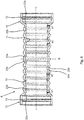
- Fig. 2 shows an embodiment of a second section 6 according to the embodiment of FIG Fig. 1 .
- the radially extending elevations 10 are designed as waves with wave crests 10a and wave troughs 10b, the wave crests 10a having a radius R1 and the wave troughs 10b having a radius R2.
- the radius R2 is different from the radius R1.
- the compressive strength of the second section 6 can advantageously be increased.
- Embodiments are also provided in which the radius R1 and the radius R2 are identical.
- the contact area 12 to the first section 5 or in the contact area 12 to the third section 8 is enlarged by the formation of a groove 13, so that an advantageous material connection is realized.
- the groove 13 In the assembled state, the groove 13 also interacts with a spring 14 in a form-fitting manner.
- the fluid distribution module 1 also has a holding frame 15 with which the fluid distribution module 1 can be fastened.
- a seal 16 is arranged on the second module interface 7, a seal 17 each being arranged on the first and second distributor interfaces 3, 9. It is also provided that the seals 16, 17 are integrally formed.
- Fig. 3 shows an embodiment of a second section 6, the wall thickness of which varies, namely is convex in the direction of the central region 18, so that the greatest wall thickness is present in the central region 18, which decreases in the direction of the two end regions.
- the radii R1 and R2 for wave crests 10a and wave troughs 10b are identical in this embodiment.
- Fig. 4 shows part of an embodiment of a temperature control system 19 with two cooling elements 20 designed as cooling plates as well as a first fluid distribution module 1a and a second fluid distribution module 1b, which fluidly connect the cooling elements 20.
- the fluid distribution modules 1 a, 1 b are connected to one another via the first module interface 2 and the second module interface 7.
- the second fluid distribution module 1b also has an end cap 21 at its second module interface 7, so that the flow is guided exclusively through the cooling element 20 guided with the second fluid distribution module 1b.
- the cooling elements 20 are already fixed in a frame - not shown - prior to the assembly of the fluid distributor modules 1a, 1b, so that the assembly of the Fluid distribution modules 1a, 1b is simplified in that the second section 6 of the first fluid distribution module 1a can be flexibly deformed.
- Fig. 5 shows a further embodiment of a fluid distribution module 1 in a sectional side view.
- the module interface 2 is connected to the distributor interfaces 3, 9 via the fluid channel 4 and the fluid channel side paths 4a.
- the fluid channel 4 is closed at the end along the longitudinal axis opposite the module interface 2.
- the fluid distribution module 1 serves as the last module of a flow or return, so that no further fluid distribution module 1 is flowed through here, but only the connected cooling element - not shown here.
- Fig. 6 shows an embodiment of a second section 6 for a fluid distribution module 1, for example according to the embodiment of FIG Fig. 1 .
- the radially extending elevations 10 are provided on the inside and on the outside due to the constant wall thickness.
- the respective adjacent flanks 22a, 22b have different flank inclinations.
- the adjacent flanks 22a, 22b are inclined in opposite directions with respect to the longitudinal axis L and have a different angle ⁇ 1, ⁇ 2 in terms of amount, that is to say a different flank inclination.
- the flank 22a with the angle ⁇ 1 is steeper in terms of amount than the flatter flank 22b with the angle ⁇ 2 to the longitudinal axis L.
- the steeper flanks 22a are aligned in such a way that they lie opposite the ends.
- the flatter flanks 22b face away from the nearest end in order to enable removal from the mold in the direction of the respective end, that is to say to remove an inner core in the direction of the end.
- two flanks 23a, 23b with identical flank inclination are arranged in the middle of the second section.
- the flanks 23a, 23b each correspond to a flatter flank 22b with a different orientation.
- a line of symmetry S lies between the two flanks 23a, 23b. It is also provided that the flanks 23a, 23b of a steeper one Flank 22a correspond.
- flanks 22a, 22b On the flanks 23a, 23b or on the line of symmetry S, the alternating arrangement of the flanks 22a, 22b is reversed, starting from the respective end.
- the alternating arrangement of steeper flanks 22a and flatter flanks 22b begins, starting from each end, with a steeper flank 22a in each case.
- the flatter flanks 22b are each inclined in the demolding direction - starting from the line of symmetry S - in the direction of the respective end of the second section 6.
- the contact surface 12 to the first section 5 or in the contact area 12 to the third section 8 - for example according to FIG Fig. 1 - is the contact surface enlarged by the formation of a groove 13, so that an advantageous material connection is realized.
- the groove 13 In the assembled state, the groove 13 also interacts positively with a spring 14.
- the invention is not restricted to the illustrated and described exemplary embodiments, but rather also includes all embodiments that have the same effect within the meaning of the invention. It is expressly emphasized that the exemplary embodiments are not limited to all features in combination; rather, each individual sub-feature can also have an inventive significance in isolation from all other sub-features. Furthermore, the invention has not yet been restricted to the combination of features defined in claim 1, but can also be defined by any other combination of specific features of all of the individual features disclosed. This means that in principle practically every individual feature of claim 1 can be omitted or replaced by at least one individual feature disclosed elsewhere in the application.
Landscapes
- Engineering & Computer Science (AREA)
- Manufacturing & Machinery (AREA)
- Chemical & Material Sciences (AREA)
- Chemical Kinetics & Catalysis (AREA)
- Electrochemistry (AREA)
- General Chemical & Material Sciences (AREA)
- Secondary Cells (AREA)
- Battery Mounting, Suspending (AREA)
Description
- Die vorliegende Erfindung betrifft ein Fluidverteilermodul für ein modulares Temperiersystem eines Energiespeichers, insbesondere ein Kühlsystem für Fahrzeugbatterien, mit mindestens einer ersten Modulschnittstelle zum Anschluss an mindestens ein weiteres Fluidverteilermodul, mindestens einer ersten Verteilerschnittstelle zum Anschluss an mindestens ein Kühlelement und mindestens einen Fluidkanal sowie ein Temperiersystem.
- Batterien bzw. Akkuzellen von Elektro- und Hybridfahrzeugen müssen in einem definierten Temperaturfenster betrieben werden, um deren Haltbarkeit zu gewährleisten und eine Schädigung zu vermeiden. Aus dem Stand der Technik bekannte Temperiersysteme weisen durchströmbare Kühlplatten, insbesondere Aluminium-Kühlplatten, auf, an denen die Akkuzellen positioniert sind. Die Größe und Anzahl der Kühlplatten ist abhängig von der Geometrie und Anzahl der Akkuzellen.
- Um eine homogene Temperierung zu ermöglichen, werden die Kühlplatten typischerweise einzeln mit einem Temperiermedium, beispielsweise einem Gemisch aus Wasser und Glykol, durchströmt. Die Zu- und Abläufe der Kühlplatten werden jeweils in eine Sammelleitung als Vor- bzw. Rücklauf geführt.
- Neben der Verteilung des Temperiermediums auf die einzelnen Kühlplatten muss das Temperiersystem, insbesondere die darin angeordneten Fluidverteilermodule, die Toleranzen zwischen den Kühlplatten und zwischen den Anschlüssen an einer Kühlplatte ausgleichen sowie einen einfachen Ein- und Ausbau ermöglichen.
- Aus dem Stand der Technik bekannte Temperiersysteme werden üblicherweise aus einer Vielzahl von einzelnen Verbindern und Rohrstücken montiert. Beispielsweise erfolgt die Montage durch Aufdornen oder Zusammenstecken.
-
WO 2017/095172 A1 offenbart ein Kühlungssystem für Batterien. Das Kühlungssystem umfasst eine Mehrzahl von Rohrleitungen, die zu einem Fluidsystem verbunden sind. Das Kühlsystem umfasst zumindest zwei unterschiedliche Materialien für die Rohrleitungen. Die geraden Rohrabschnitte sind aus einem härteren Kunststoff gefertigt. Die gekrümmten Rohrabschnitte sind aus einem flexiblen Gummi mit hoher Elastizität hergestellt. Die geraden und die gekrümmten Elemente sind durch thermisches Schrumpfen zusammengefügt. -
EP 2 980 882 A1 offenbart einen Rahmen für elektrochemische Zellen mit einem integrierten Kühlkanal. In dem Kühlkanal sind Steckstücke angeordnet, um eine Verbindung herzustellen. Der Rahmen und das Steckstück können aus gleichen oder unterschiedlichen Materialien hergestellt sein. -
DE 20 2015 103 455 U1 offenbart ein Verbindungselement zum Verbinden eines Rohres mit einer Komponente einer Klimaanlage. Das Verbindungselement umfasst einen Grundkörper, einen Stutzen und zwei Dichtelemente, wobei die Dichtelemente stoffschlüssig mit dem Stutzen verbunden sind. -
EP 3 188 303 A1 offenbart eine Kühleinrichtung, die zwischen einer Mehrzahl von Batteriezellen für ein elektrisches Fahrzeug angeordnet wird. Die Kühleinrichtung umfasst eine oder mehrere Fluidleitungen, die mäanderförmig zwischen den einzelnen Batteriezellen angeordnet werden. Um den Wärmeübergang zwischen den Batteriezellen und dem in den Fluidleitungen führbaren Fluid zu verbessern, ist vorgesehen, an den Fluidleitungen Formkörper anzuordnen, die sich der Kontur der Batteriezellen anpassen. - Die aus dem Stand der Technik bekannten Temperiersysteme weisen dabei den Nachteil auf, dass ein umfangreicher Montageaufwand erforderlich ist, und dass das Vorhandensein einer Vielzahl von Verbindungsstellen das Leckagerisiko steigert.
- Der vorliegenden Erfindung liegt daher die Aufgabe zugrunde, ein Fluidverteilermodul für ein modulares Temperiersystem und ein Temperiersystem anzugeben, bei dem der Montageaufwand reduziert ist, und bei dem die Anzahl der Verbindungsstellen reduziert ist.
- Die vorgenannte Aufgabe ist bei einem gattungsgemäßen Fluidverteilermodul gelöst durch die kennzeichnenden Merkmale des Anspruchs 1, nämlich dadurch, dass mindestens ein erster Abschnitt des Fluidverteilermoduls aus einem ersten Material und mindestens ein zweiter Abschnitt aus einem, insbesondere von dem ersten Material verschiedenen, zweiten Material gebildet ist, dass der zweite Abschnitt zumindest teilweise eine geringere Steifigkeit als der erste Abschnitt aufweist, und dass der erste Abschnitt und der zweite Abschnitt stoffschlüssig aneinander angeformt sind
- Das Fluidverteilermodul ist ein Bauteil zur Herstellung eines fluidführenden Temperiersystems für einen Energiespeicher, bevorzugt eines fluidführenden Kühlsystems für Fahrzeugbatterien, insbesondere zum Leiten eines unter Druck stehenden Fluids. Das Fluidverteilermodul weist mindestens eine erste Modulschnittstelle auf, die dazu ausgebildet und eingerichtet ist, das Fluidverteilermodul mit mindestens einem weiteren Fluidverteilermodul zu verbinden, insbesondere fluidtechnisch zu verbinden. Eine Mehrzahl miteinander verbundener Fluidverteilermodule bilden beispielsweise einen Vor- oder Rücklauf eines Temperiersystems. Alternativ dazu ist auch vorgesehen, dass eine Mehrzahl Fluidverteilermodule für eine serielle Durchströmung von Kühlelementen ausgebildet und angeordnet sind.
- Die Modulschnittstelle ist beispielsweise als Steckverbinder, Rastverbinder, Klemmverbinder, Bajonettverschluss oder als anderer lösbarer oder unlösbarer Verbinder ausgebildet. Beispielsweise ist die erste Modulschnittstelle als einzusteckender oder aufnehmender Teil eines Steckverbinders ausgebildet. Die Modulschnittstelle ermöglicht die Herstellung einer dichtenden Verbindung zwischen zwei Fluidverteilermodulen.
- Ferner weist das Fluidverteilermodul mindestens eine erste Verteilerschnittstelle auf, die dazu ausgebildet und eingerichtet ist, das Fluidverteilermodul mit mindestens einem Kühlelement, insbesondere mindestens einer Kühlplatte, zu verbinden. Die Verteilerschnittstelle ist beispielsweise als Steckverbinder, Kupplung, Rastverbinder, Klemmverbinder, Bajonettverschluss oder als anderer lösbarer oder unlösbarer Verbinder ausgebildet. Vorzugsweise ist die Verteilerschnittstelle in einem Winkel von 90° zur Modulschnittstelle angeordnet. Das Fluidverteilermodul weist zudem mindestens einen Fluidkanal auf, der sich insbesondere zwischen Modulschnittstelle und Verteilerschnittstelle erstreckt.
- Das Fluidverteilermodul zeichnet sich dadurch aus, dass mindestens ein erster Abschnitt des Fluidverteilermoduls aus einem ersten Material und mindestens ein zweiter Abschnitt aus einem, insbesondere von dem ersten Material verschiedenen, zweiten Material gebildet ist, wobei der zweite Abschnitt eine geringere Steifigkeit als der erste Abschnitt aufweist. Unter Steifigkeit wird der Widerstand des ersten und zweiten Abschnitts gegen elastische Verformung durch eine Kraft oder ein Moment verstanden. Die geringere Steifigkeit wird durch die Materialwahl und/oder die geometrische Gestaltung des ersten Abschnitts und/oder des zweiten Abschnittes erreicht. Beispielsweise ist das zweite Material weicher, weist also eine geringere Härte auf, und/oder weist einen kleineren Elastizitätsmodul als das erste Material auf. Insbesondere weist das zweite Material bzw. der zweite Abschnitt einen geringeren Widerstand gegen elastische Verformung als das erste Material bzw. der erste Abschnitt auf. Der zweite Abschnitt bzw. das zweite Material ist vorzugsweise dehnbarer, biegbarer und/oder stauchbarer als das erste Material bzw. der erste Abschnitt. Bevorzugt wird die geringere Steifigkeit des zweiten Abschnitts ausschließlich durch die Materialwahl erzielt, also dadurch, dass das zweite Material weicher als das erste Material ist.
- Vorzugsweise begrenzen der erste Abschnitt und/oder der zweite Abschnitt zumindest einen Teil des Fluidkanals. Der erste Abschnitt und der zweite Abschnitt sind aneinander angeformt, insbesondere bei der Herstellung aneinander angeformt. Unter "anformen" ist hier das Herstellen einer stoffschlüssigen Verbindung zu verstehen, die beim Herstellen des ersten und/oder des zweiten Abschnitts ausgebildet wird. Beispielsweise ist der erste Abschnitt an den zweiten oder der zweite Abschnitt an den ersten angeformt oder beide werden gleichzeitig bei der Herstellung aneinander angeformt. Beispielsweise ist das Fluidverteilermodul als Mehrkomponentenbauteil mit einem Mehrkomponenten-Fertigungsverfahren hergestellt, beispielsweise Mehrkomponenten-Spritzguss oder ein additives Herstellungsverfahren, z. B. 3D-Druck. Das Fluidverteilermodul mit dem ersten Abschnitt und dem zweiten Abschnitt ist einstückig aus zwei unterschiedlichen Materialien hergestellt.
- Es ist ferner vorgesehen, dass ein vierter oder fünfter Abschnitt ausgebildet ist, wobei der vierte oder fünfte Abschnitt bzw. das Material ebenfalls eine geringere Steifigkeit aufweist als im ersten Abschnitt. Das Fluidverteilermodul weist also eine Mehrzahl flexibler Abschnitte auf, die eine einfache Verformung bei der Montage ermöglichen.
- Durch die Verwendung von zwei unterschiedlichen Materialien können verschiedene mechanische Eigenschaften in einem Fluidverteilermodul kombiniert und integriert werden. Dadurch, dass der zweite Abschnitt eine geringere Steifigkeit aufweist, wird die Montage vereinfacht und Toleranzen können durch elastische Verformung des zweiten Abschnitts ausgeglichen werden. Bei der Montage kann eine temporäre Verformung des zweiten Abschnitts auf einfache Weise erfolgen, um das Fluidverteilermodul in seine Einbausituation zu verbringen. Des Weiteren können mit dem zweiten Abschnitt Druckpulsationen im Temperiersystem und eine mögliche Volumenzunahme des Fluids ausgeglichen werden.
- Dadurch, dass der erste Abschnitt und der zweite Abschnitt aneinander angeformt sind, wird die Anzahl an Verbindungsschnittstellen und damit das Leckagerisiko reduziert. Gleichzeitig werden auf einfache Weise Reinheits- und Qualitätsanforderungen erfüllt, da keine Nachbearbeitung erforderlich ist. Eine Nachbearbeitung kann insbesondere deshalb entfallen, da nach der Herstellung nur ein einstückiges Bauteil vorliegt.
- Ferner ist vorgesehen, dass eine zweite Verteilerschnittstelle zum Anschluss an ein Kühlelement vorhanden ist. Durch die zweite Verteilerschnittstelle kann der Durchfluss durch ein angeschlossenes Kühlelement gesteigert werden. Die zweite Verteilerschnittstelle ist beispielsweise parallel zur ersten Verteilerschnittstelle angeordnet.
- Zudem ist vorgesehen, dass die erste Verteilerschnittstelle und die zweite Verteilerschnittstelle am ersten Abschnitt ausgebildet sind. Der erste Abschnitt dient in diesem Fall der Verbindung mit einem Kühlelement, während der zweite Abschnitt und gegebenenfalls der dritte Abschnitt lediglich der Verbindung mit einem weiteren Fluidverteilermodul bzw. der Steigerung der Flexibilität dienen. Es ist auch vorgesehen, dass die erste Verteilerschnittstelle und die zweite Verteilerschnittstelle einstückig mit dem ersten Abschnitt ausgebildet sind und insbesondere aus dem ersten Material ausgebildet sind.
- Die Modulschnittstelle gewährleistet zudem ein einfaches Zusammenfügen von mindestens zwei Fluidverteilermodulen, wodurch zwei nebeneinander angeordnete Kühlelemente mit einem Fluid durchströmbar werden. Der modulare Aufbau ermöglicht zudem die Realisierung von Temperiersystemen verschiedenster Größe.
- Gemäß einer ersten Ausgestaltung des Fluidverteilermoduls ist vorgesehen, dass eine zweite Modulschnittstelle zum Anschluss an ein weiteres Fluidverteilermodul vorhanden ist, insbesondere dass die zweite Modulschnittstelle am zweiten Abschnitt oder an einem dritten Abschnitt ausgebildet ist. Die zweite Modulschnittstelle ist so ausgebildet, dass eine Verbindung mit einem weiteren Fluidverteilermodul hergestellt werden kann. Beispielsweise ist die zweite Modulschnittstelle als Steckverbinder oder als schlauchförmiges Anschlussstück ausgebildet. Vorzugsweise ist die zweite Modulschnittstelle korrespondierend zur ersten Modulschnittstelle ausgebildet. Vorzugsweise ist die erste Modulschnittstelle als aufnehmender Teil eines Steckverbinders und die zweite Modulschnittstelle als einzusteckender Teil eines Steckverbinders ausgebildet. Zwei Fluidverteilermodule können so auf einfache Weise durch Zusammenstecken mittels der ersten und der zweiten Modulschnittstelle miteinander dichtend verbunden werden. Beispielsweise sind die erste Modulschnittstelle und die zweite Modulschnittstelle in Abschnitten angeordnet, die aus dem ersten Material hergestellt sind. Vorzugsweise sind die erste Modulschnittstelle und die zweite Modulschnittstelle auf einer gemeinsamen Längsachse des Fluidverteilermoduls angeordnet.
- Insbesondere um den Herstellungsprozess zu vereinfachen, ist gemäß einer weiteren Ausgestaltung des Fluidverteilermoduls vorgesehen, dass der Fluidkanal zumindest im Verlauf zwischen erster Modulschnittstelle und zweiter Modulschnittstelle einen konstanten Querschnitt aufweist. Insbesondere verläuft der Fluidkanal entlang der Längsachse des Fluidverteilermoduls. Dadurch ist das Fluidverteilermodul beispielsweise bei einer Herstellung durch Spritzgießen auf einfache Weise entformbar. Ferner wird gewährleistet, dass keine Verwirbelungen bzw. Druckverluste erzeugt werden. Vorzugsweise ist die erste Verteilerschnittstelle über einen von dem Fluidkanal mit dem konstanten Querschnitt abgehender Seitenarm des Fluidkanals fluidtechnisch angebunden.
- Als besonders vorteilhaft hat sich gemäß einer weiteren Ausgestaltung herausgestellt, wenn vorgesehen ist, dass ein dritter Abschnitt ausgebildet ist, und dass der dritte Abschnitt, insbesondere an den zweiten Abschnitt, angeformt ist. Bevorzugt, dass der zweite Abschnitt zwischen dem ersten Abschnitt und dem dritten Abschnitt angeordnet ist, insbesondere ist vorgesehen, dass der dritte Abschnitt aus dem ersten Material ausgebildet ist. Vorzugsweise sind der erste Abschnitt und der dritte Abschnitt aus dem gleichen Material ausgebildet. Dadurch, dass der zweite Abschnitt zwischen dem ersten Abschnitt und dem dritten Abschnitt ausgebildet ist, wird eine gesteigerte Flexibilität und Beweglichkeit im zweiten Abschnitt gewährleistet, die die Montage vereinfachen.
- Der erste Abschnitt, der zweite Abschnitt und der dritte Abschnitt sind jeweils aneinander angeformt, so dass sie einstückig ausgebildet sind, insbesondere gemeinsam hergestellt werden. Dadurch wird die Anzahl an erforderlichen Verbindungsstellen für ein Temperiersystem weiter verringert.
- Als besonders vorteilhaft hat sich zudem herausgestellt, wenn vorgesehen ist, dass mindestens ein Abschnitt der ersten Verteilerschnittstelle und/oder der zweiten Verteilerschnittstelle aus dem zweiten Material ausgebildet ist. Vorzugsweise ist der aus dem zweiten Material ausgebildete Abschnitt der ersten oder zweiten Verteilerschnittstelle jeweils an die verbleibenden Abschnitte der jeweiligen Verteilerschnittstelle angeformt, so dass sie einstückig ausgebildet sind. Durch das Vorhandensein eines Abschnitts aus einem zweiten Material mit einer geringeren Steifigkeit als das erste Material wird die Montage des Fluidverteilermoduls vereinfacht. Die zweite Verteilerschnittstelle ist vorzugsweise identisch wie die erste Verteilerschnittstelle ausgebildet.
- Vorzugsweise ist gemäß einer weiteren Ausgestaltung zur Vereinfachung der Montage vorgesehen, dass die Länge des zweiten Abschnitts mindestens 5 % der Gesamtlänge des Fluidverteilermoduls, insbesondere zwischen den äußeren Enden der ersten und zweiten Modulschnittstelle, bevorzugt zwischen 5 % und 35 % der Gesamtlänge, entspricht. Aufgrund dieser Mindestlänge kann gewährleistet werden, dass der zweite Abschnitt eine ausreichende Flexibilität bzw. Auslenkbarkeit zur Vereinfachung der Montage aufweist. In diesem Zusammenhang ist gemäß einer weiteren Ausgestaltung zudem vorteilhaft, wenn der zweite Abschnitt eine Länge zwischen 15 mm und 100 mm aufweist.
- Es hat sich zudem gemäß einer weiteren Ausgestaltung als vorteilhaft herausgestellt, wenn vorgesehen ist, dass die minimale Länge des zweiten Abschnitts mindestens dem minimalen Innendurchmesser des Fluidkanals zwischen erster Modulschnittstelle und zweiter Modulschnittstelle entspricht. Die Länge des zweiten Abschnitts entspricht folglich mindestens dem kleinsten Durchmesser des Fluidkanals im Verlauf zwischen erster und zweiter Modulschnittstelle. Dadurch wird gewährleistet, dass eine vorteilhafte Montage realisierbar ist.
- Das Fluidverteilermodul wird gemäß einer weiteren Ausgestaltung dadurch fortgebildet, dass die erste Verteilerschnittstelle und/oder die zweite Verteilerschnittstelle einen Montageversatz aufweisen, und dass die Länge des zweiten Abschnitts etwa dem doppelten Wert des Montageversatzes entspricht. Der Montageversatz ist der Weg, den die erste Verteilerschnittstelle und/oder die zweite Verteilerschnittstelle beim Aufschieben bzw. Einschieben in bzw. auf ein Kühlelement vollzieht, um fluidtechnisch verbunden zu werden. Dieser Weg entspricht dem Montageversatz. Beispielsweise handelt es sich bei dem Montageversatz um den Steckweg eines Steckverbinders. Dadurch, dass die Länge des zweiten Abschnitts etwa dem doppelten Wert des Montageversatzes entspricht, kann gewährleistet werden, dass eine Mehrzahl von Fluidverteilermodulen nebeneinander und nacheinander auf einfache Weise montierbar sind. Beispielsweise beträgt der Montageversatz zwischen 15 mm und 25 mm, so dass die bevorzugte Länge des zweiten Abschnitts zwischen 30 mm und 50 mm, vorteilhaft 40 mm, entspricht.
- Um eine ausreichende Druckfestigkeit des zweiten Abschnitts zu gewährleisten, ist gemäß einer weiteren Ausgestaltung vorzugsweise vorgesehen, dass der zweite Abschnitt außenseitig und/oder innenseitig eine Mehrzahl von, insbesondere radial umlaufenden, Erhebungen, bevorzugt Rippen oder Wellen, aufweist, insbesondere dass der zweite Abschnitt an seiner den Fluidkanal bildenden Innenfläche glatt ausgebildet ist. Die auf der Außenseite und/oder der Innenseite ausgebildeten Erhebungen, insbesondere Rippen oder Wellen, besonders bevorzugt gleichmäßig verteilte Rippen oder Wellen, verstärken die Wandstärke des zweiten Abschnitts lokal, wodurch dessen Druckfestigkeit gesteigert wird. Gleichzeitig wird durch die Beabstandung der Erhebungen zueinander eine Biegbarkeit des zweiten Abschnitts zuverlässig gewährleistet.
- Der zweite Abschnitt ist beispielsweise als Wellrohr mit glatter Innenfläche ausgebildet. Durch die glatte Innenfläche werden Verwirbelungen bzw. eine nachteilige Beeinflussung der Strömung verhindert. Insbesondere ist der Innendurchmesser zumindest im zweiten Abschnitt konstant. Zudem kann eine einfache Entformbarkeit beim Herstellen mittels Spritzgießen gewährleistet werden. Die Höhe der Erhebungen ausgehend von der Wandstärke in Bereichen ohne Erhebung entspricht vorzugsweise etwa der Wandstärke, so dass der zweite Abschnitt im Bereich der Erhebungen eine zweifache Wandstärke aufweist.
- Es ist ferner gemäß einer weiteren Ausgestaltung bevorzugt, wenn vorgesehen ist, dass die Erhebungen in Form von Wellen unterschiedliche Radien für Wellenberge und Wellentäler aufweisen, insbesondere dass der Abstand zwischen zwei Wellenbergen zwischen 3 mm und 10 mm beträgt. Bei einer derartigen Ausgestaltung hat sich herausgestellt, dass die Verformbarkeit des zweiten Abschnitts bei gleichzeitig ausreichender Druckstabilität zuverlässig gewährleistet werden kann.
- Ferner ist gemäß einer weiteren Ausgestaltung der Erfindung vorgesehen, dass die Wandstärke im zweiten Abschnitt zwischen zwei Erhebungen zwischen 5 % und 20 %, insbesondere etwa 7 %, des Innendurchmessers des Fluidkanals im zweiten Abschnitt entspricht, insbesondere des Fluidkanals zwischen der ersten Modulschnittstelle und der zweiten Modulschnittstelle. Diese Mindestwandstärke gewährleistet eine ausreichende Druckfestigkeit im zweiten Abschnitt.
- Eine weitere Ausgestaltung der Erfindung sieht vor, dass die Erhebungen, insbesondere auf der Innenseite, in Form von Wellen unterschiedliche Flankenneigungen, insbesondere in Bezug auf eine Längsachse L, an benachbarten Flanken aufweisen. Insbesondere ist ein Wellenprofil mit unterschiedlichen Winkeln der Flanken vorgesehen. Die Flankenneigungen erstrecken sich über den gesamten Umfang, insbesondere sind die Flankenneigungen über den jeweiligen Umfang konstant. Vorzugsweise sind die von einem Ende des zweiten Abschnitts weggeneigten Flanken weniger stark geneigt, als die dem Ende zugewandten bzw. gegenüberliegenden Flanken. Vorzugsweise weisen steilere Flanken einen Winkel α2 zwischen 40° und 75°, bevorzugt 50°, und flachere Flanken einen Winkel α1 zwischen 20° und 40°, bevorzugt 30°, insbesondere zu einer Längsachse L, auf. Die benachbarten Flanken sind grundsätzlich entgegengesetzt zueinander geneigt, allerdings weisen sie betragsmäßig einen anderen Winkel - eine andere Neigung - auf.
- Eine gleiche Systematik ergibt sich, wenn die Flanken gewölbt sind und einen Flankenradius aufweisen. Die Flanken mit einem größeren Radius entsprechen den flacheren Flanken und die Flanken mit einem kleineren Radius entsprechen den steileren Flanken. Auf einen kleineren Flankenradius folgt ein größerer Flankenradius und umgekehrt.
- Durch die flacheren Flanken bzw. größeren Flankenradien ist eine einfache Entformbarkeit bei der Herstellung entlang der flacheren Flanken bzw. Flanken mit größerem Flankenradius gewährleistet, während die steileren Flanken bzw. kleineren Flankenradien für eine gesteigerte Flexibilität des zweiten Abschnitts sorgen.
- Insbesondere um eine Entformung in zwei Richtungen zu ermöglichen, ist vorgesehen, dass mindestens zwei benachbarte Flanken im Verlauf des zweiten Abschnitts mit gleicher Flankenneigung oder gleichem Flankenradius an gegenüberliegenden Flanken vorgesehen sind. Die Flanken mit den unterschiedlichen Flankenneigungen sind so angeordnet, dass ausgehend von jeder Endseite zunächst eine steilere Flanke angeordnet ist. Es ist auch vorgesehen, dass zunächst eine flachere Flanke angeordnet ist. Ausgehend von den beiden Endseiten sind die jeweiligen flacheren Flanken bzw. die steileren Flanken im gleichen Winkel, aber für jede Endseite entgegengesetzt geneigt. Anschließend folgt jeweils eine steilere Flanke auf eine flachere Flanke bzw. umgekehrt. Vorzugsweise in der Mitte des zweiten Abschnitts, insbesondere an einer Symmetrielinie S, treffen zwei entgegengesetzt geneigte flachere Flanken aufeinander. An dieser Stelle erfolgt bei der Herstellung die Entformung in entgegengesetzte Richtungen, so dass eine Entformung vorteilhaft entlang der flacheren Flanken erfolgen kann. Die flacheren Flanken sind in Entformungsrichtung geneigt bzw. angeordnet.
- Die Erhebungen mit den flacheren und steileren Flanken bzw. größeren und kleineren Flankenradien sind vorzugsweise zumindest auf der Innenseite angeordnet. Bei konstanter Wandstärke des zweiten Abschnitts sind diese ebenfalls auf der Außenseite angeordnet.
- Die Druckfestigkeit im zweiten Abschnitt lässt sich insbesondere dadurch steigern, dass der zweite Abschnitt eine zumindest abschnittsweise, insbesondere im Bereich der Wellentäler, variierende Wandstärke aufweist, vorzugsweise eine in Richtung seines Mittelbereiches ballig ausgebildete Wandstärke aufweist. Folglich variiert die Mindestwandstärke im Bereich der Wellentäler derart, dass die Mindestwandstärke in der Mitte des zweiten Abschnitts am größten ist und in Richtung der beiden Enden abnimmt. Ferner ist vorgesehen, dass die Wandstärke des zweiten Abschnitts ausgehend von einer gleichen Wandstärke an den Enden in Richtung der Mitte zunimmt. Alternativ oder zusätzlich dazu ist vorgesehen, dass der Innendurchmesser ausgehend von den beiden Enden in Richtung der Mitte abnimmt. Dadurch kann eine gute Innendruckresistenz bei gleichzeitig guter Entformbarkeit eines Innenkerns gewährleistet werden.
- Es ist auch vorgesehen, dass der zweite Abschnitt eine im Wesentlichen konstante Wandstärke aufweist. Vorzugsweise beträgt die Wandstärke zwischen 0,5 mm und 2 mm, insbesondere 1 mm.
- Es ist auch vorgesehen, dass der zweite Abschnitt im Querschnitt eine ballige Wandstärke aufweist, und/oder dass die Innenwandung im drucklosen Zustand nach innen gewölbt ist. Wird das Temperiersystem dann mit einem Druck beaufschlagt, wird der zweite Abschnitt durch den anliegenden Druck derart nach außen gewölbt, dass im druckbeaufschlagten Betriebszustand im zweiten Abschnitt ein konstanter Durchmesser ausgebildet ist.
- Die Montage des Fluidverteilermoduls lässt sich insbesondere dadurch weiter vereinfachen, dass das zweite Material eine größere Elastizität und/oder geringere Härte als das erste Material aufweist. Durch diese Ausgestaltung ist das Fluidverteilermodul im zweiten Abschnitt auf einfache Weise verformbar und weist eine geringere Steifigkeit auf, wodurch die Montage an den Kühlelementen vereinfacht wird.
- Gemäß einer weiteren Ausgestaltung hat sich zudem als vorteilhaft herausgestellt, wenn das erste Material aus Polypropylen (PP), bevorzugt mit einem Anteil von bis zu 50 % Glasfasern, ist und/oder das zweite Material ein thermoplastisches Elastomer (TPE), bevorzugt mit einer Härte Shore A im Bereich zwischen 40 und 95, besonders bevorzugt 60 und 90.
- Der erste und der dritte Abschnitt werden vorzugsweise aus Polypropylen (PP) hergestellt, da bei PP im Vergleich zu Polyamid (PA) die Wasseraufnahme deutlich geringer ist und somit die mechanischen Langzeiteigenschaften besser sind. Ferner weist PP gegenüber PA eine erheblich geringere Quellung in Wasser/Glykol auf, wodurch sich die Spannungen im Betriebszustand reduzieren. Beim Trocknen des Systems (z. B. im Servicefall oder bei längeren Abstellzeiten) wird das Risiko von möglichen Spannungsrissen infolge der Rücktrocknung ausgeschlossen. In Abhängigkeit der erforderlichen Festigkeit wird der erste Abschnitt und/oder der dritte Abschnitt nach Bedarf mit einem Glasfaseranteil verstärkt (bis zu 50%).
- Der zweite Abschnitt wird vorzugsweise aus einem thermoplastischen Elastomer (TPE) hergestellt, das eine stoffschlüssige bzw. chemische Verbindung zum ersten bzw. dritten Abschnitt aufweist. Hierzu wird ein TPE mit einem geringen Druckverformungsrest bzw. hoher Kriechbeständigkeit verwendet, um die Aufweitung des Ausgleichselementes unter Innendruckbelastung zu minimieren. Über die Shore-Härte des TPE kann der Werkstoff anwendungsspezifisch an die Druckanforderungen des Temperiermediums im Temperiersystem angepasst werden. Durch diese Materialwahl wird sichergestellt, dass das Fluidverteilermodul eine hohe Druckfestigkeit bei gleichzeitig montagefreundlichen Materialeigenschaften aufweist.
- Ferner ist vorzugsweise vorgesehen, dass das zweite Material ein thermoplastisches Polyolefin (TPO) oder ein thermoplastischen Polyolefine-Vulkanisat (TPV) ist oder der zweite Abschnitt ein derartiges Material aufweist. Vorzugsweise ist der zweite Abschnitt aus einem thermoplastischen Polyolefin (TPO) oder einem thermoplastischen Polyolefine-Vulkanisat (TPV) hergestellt. Insbesondere weist der zweite Abschnitt eine Shore-Härte größer gleich 35D, bevorzugt 40D, auf. Dadurch kann eine gute Langzeit-Innendruckbeständigkeit bei guter Haftung zum ersten Abschnitt erreicht werden.
- Ferner ist gemäß einer weiteren Ausgestaltung vorgesehen, dass das zweite Material strahlvernetzt ist. Das zweite Material bzw. der zweite Abschnitt ist mindestens einer Strahlvernetzung unterzogen worden. Bei der Strahlvernetzung lösen beispielsweise energiereiche Beta- oder Gammastrahlen chemische Reaktionen in dem Kunststoff aus und führen zu einer Vernetzung der Moleküle. Das hat den Vorteil, dass eine gute Innendruckfestigkeit bei gleichzeitig guter Langzeit-Kriechbeständigkeit und Temperaturbeständigkeit erreicht wird.
- Des Weiteren hat sich gemäß einer weiteren Ausgestaltung als vorteilhaft herausgestellt, wenn das erste Material Polyamid 6.10 (PA 6.10) oder Polyamid 12 (PA 12) und/oder das zweite Material ein thermoplastisches Elastomer auf Urethanbasis (TPU) ist, bevorzugt mit einer Glasfaserfüllung, besonders bevorzugt mit einer Härte Shore D größer gleich 50.
- Es ist auch vorgesehen, den ersten Abschnitt - wie vorstehend beschrieben - aus Polypropylen auszubilden und den zweiten Abschnitt aus einem thermoplastischen Elastomer auf Urethanbasis auszubilden. Gleichermaßen ist auch eine Kombination von Polyamid, beispielsweise PA 6.10 oder PA 12, im ersten Abschnitt und einem thermoplastischen Elastomer im zweiten Abschnitt vorgesehen. Bei einer Kombination von Polypropylen mit einem thermoplastischen Elastomer auf Urethanbasis wird eine - zumindest lokale - Plasmaaktivierung des Polypropylen durchgeführt.
- TPU weist zum einen eine sehr gute Langzeitfestigkeiten auf und kann zum anderen durch Glasfaserverstärkungen hinsichtlich der Innendruckresistenz optimiert werden. TPU als Werkstoff erfordert PA als Material im ersten Abschnitt, um eine robuste Verbindung zu erreichen. In diesem Fall kommt PA 6.10 bzw. PA12 zum Einsatz, da diese Polyamide eine deutlich geringere Wasseraufnahme im Vergleich zu PA6 bzw. PA6.6 Typen haben. PA6.10 hat im Vergleich zum PA12 bessere mechanische Eigenschaften und eine höhere Temperaturbeständigkeit. Auch diese Materialwahl gewährleistet gute Materialeigenschaften bei gleichzeitiger Montagefreundlichkeit.
- Die Stabilität des Fluidverteilermoduls und der Verbindung zwischen den Abschnitten lässt sich insbesondere dadurch steigern, dass die Fläche in einem Kontaktbereich zwischen dem ersten Abschnitt und dem zweiten Abschnitt und/oder zwischen dem zweiten Abschnitt und dem dritten Abschnitt, insbesondere gegenüber einer kreiszylindrischen Fläche, vergrößert ist, vorzugsweise durch Wellen und Vorsprünge und/oder Rücksprünge. Die Abschnitte sind jeweils aneinander angeformt, so dass die Vergrößerung der Kontaktfläche zu einer größeren Fläche für eine stoffschlüssige Verbindung führt. Ferner ist auch vorgesehen, dass in einem Kontaktbereich zwischen dem ersten Abschnitt und dem zweiten Abschnitt und/oder dem zweiten Abschnitt und dem dritten Abschnitt eine Nut-Feder-Geometrie, vorzugsweise mit mindestens einer Nut und mindestens einer Feder, ausgebildet ist. Durch eine Nut-Feder-Geometrie lässt sich ein zusätzlicher Formschluss erzeugen, der sich positiv auf die Stabilität des Fluidverteilermoduls auswirkt.
- Vorzugsweise um das Fluidverteilermodul im Einbau zu fixieren, ist gemäß einer weiteren Ausgestaltung vorgesehen, dass mindestens ein Halterahmen ausgebildet ist, insbesondere dass der Grundkörper mindestens einen Halterahmen aufweist.
- Vorzugsweise erstreckt sich der Halterahmen auf der zu den Verteilerschnittstellen gegenüberliegenden Seite. Der Halterahmen ist beispielsweise als Bügel ausgebildet und weist mindestens eine Durchgriffsöffnung auf.
- Gemäß einer weiteren Ausgestaltung des Fluidverteilermoduls ist vorgesehen, dass an der ersten Modulschnittstelle und/oder an der zweiten Modulschnittstelle und/oder an der ersten Verteilerschnittstelle und/oder an der zweiten Verteilerschnittstelle mindestens eine Dichtung angeformt ist. Vorzugsweise wird die Dichtung bereits bei der Herstellung angeformt, so dass das Fluidverteilermodul unmittelbar verwendbar ist. Dadurch, dass die Dichtung angeformt ist, ist sie bereits vorteilhaft stoffschlüssig mit der jeweiligen Schnittstelle verbunden, wodurch eine zuverlässige Dichtigkeit gewährleistet ist.
- Besonders bevorzugt ist eine Verwendung mindestens eines aus mindestens zwei Komponenten hergestellten, erfindungsgemäßen Fluidverteilermoduls zum fluidtechnischen Verbinden von Kühlelementen an einer Fahrzeugbatterie zu Temperierungszwecken.
- Die eingangs genannte Aufgabe ist ferner gelöst mit einem Kühlsystem, insbesondere für Fahrzeugbatterien, mit mindestens einer Kühlplatte und mindestens einem erfindungsgemäß ausgestalteten Fluidverteilermodul.
- In einem derartigen Kühlsystem sind vorzugsweise mindestens zwei Fluidverteilermodule mittels der Modulschnittstellen miteinander verbunden, wobei insbesondere mindestens ein Fluidverteilermodul mit einer Endkappe auf der zweiten Modulschnittstelle verschlossen ist. Durch die Endkappe wird das Ende des Gesamtfluidkanals festgelegt, so dass eine Durchströmung nur noch durch das an diesem Fluidverteilermodul angeordnete Kühlelement, nämlich durch die Verteilerschnittstellen erfolgt. Die Endkappe ist beispielsweise als separates Bauteil oder einstückig mit dem dritten Abschnitt ausgebildet. Bei einstückiger Ausgestaltung ist der dritte Abschnitt bei der Herstellung verschlossen.
- Weitere vorteilhafte Ausgestaltungen der Erfindung ergeben sich aus der folgenden Figurenbeschreibung und den abhängigen Unteransprüchen.
- Es zeigen:
- Fig. 1
- ein Ausführungsbeispiel eines Fluidverteilermoduls für ein modulares Temperiersystem in Schnittansicht,
- Fig. 2
- ein Ausführungsbeispiel eines zweiten Abschnitts für ein Fluidverteilermodul,
- Fig. 3
- ein weiteres Ausführungsbeispiel eines zweiten Abschnitts für ein Fluidverteilermodul,
- Fig. 4
- ein Ausführungsbeispiel eines Teils eines Temperiersystems,
- Fig. 5
- ein Ausführungsbeispiel eines Fluidverteilermoduls in Schnittansicht, und
- Fig. 6
- ein Ausführungsbeispiel eines zweiten Abschnitts für ein Fluidverteilermodul.
- In den verschiedenen Figuren der Zeichnung sind gleiche Teile stets mit denselben Bezugszeichen versehen.
- Zu der anschließenden Beschreibung wird beansprucht, dass die Erfindung nicht auf die Ausführungsbeispiele und dabei nicht auf alle oder mehrere Merkmale von beschriebenen Merkmalskombinationen beschränkt ist, vielmehr ist jedes einzelne Teilmerkmal des/jedes Ausführungsbeispiels auch losgelöst von allen anderen im Zusammenhang damit beschriebenen Teilmerkmalen für sich und auch in Kombination mit beliebigen Merkmalen eines anderen Ausführungsbeispiels von Bedeutung für den Gegenstand der Erfindung.
-
Fig. 1 zeigt ein Fluidverteilermodul 1 für ein modulares Temperiersystem eines Energiespeichers, insbesondere für ein Kühlsystem für eine Fahrzeugbatterie - nicht näher dargestellt. Das Fluidverteilermodul 1 weist mindestens eine erste Modulschnittstelle 2 zum Anschluss des Fluidverteilermoduls 1 an mindestens ein weiteres Fluidverteilermodul 1 auf - siehe beispielsweiseFig. 4 . Die erste Modulschnittstelle 2 ist hier als aufnehmender Teil eines Steckverbinders ausgebildet. - Das Fluidverteilermodul 1 weist ferner mindestens eine erste Verteilerschnittstelle 3 zum Anschluss an ein - beispielsweise in
Fig. 4 dargestelltes - Kühlelement 20 und mindestens einen Fluidkanal 4 auf. Die erste Verteilerschnittstelle 3 ist als einzusteckender Teil eines Steckverbinders ausgebildet. Ein erster Abschnitt 5 des Fluidverteilermoduls 1 ist aus einem ersten Material, hier Polypropylen, gebildet, während ein zweiter Abschnitt 6 aus einem von dem ersten Material verschiedenen, zweiten Material, hier ein thermoplastisches Elastomer, ausgebildet ist. Durch die Materialwahl weist der zweite Abschnitt 6 eine geringere Steifigkeit als der erste Abschnitt 5 auf, so dass sich der zweite Abschnitt 6 leichter verformen lässt als der erste Abschnitt 5. Der zweite Abschnitt 6 lässt sich während der Montage verformen, wodurch die Montage vereinfacht wird. - Dadurch, dass der erste Abschnitt 5 und der zweite Abschnitt 6 aneinander angeformt sind, sind der erste Abschnitt 5 und der zweite Abschnitt 6 einstückig ausgebildet. Das Fluidverteilermodul 1 weist ferner eine zweite Modulschnittstelle 7 auf, die als in einen aufnehmenden Teil eines Steckverbinders - gemäß der ersten Modulschnittstelle 2 - einsteckbarer Teil eines Steckverbinders ausgebildet ist.
- Die zweite Modulschnittstelle 7 ist an einem dritten Abschnitt 8 ausgebildet, der an den zweiten Abschnitt 6, identisch wie an den ersten Abschnitt 5, angeformt ist. Der erste Abschnitt 5, der zweite Abschnitt 6 und der dritte Abschnitt 8 sind folglich einstückig ausgebildet. Ferner ist der dritte Abschnitt 8 aus dem ersten Material ausgebildet, so dass der zweite Abschnitt 6 aufgrund seiner geringeren Steifigkeit ein flexibles Verbindungsglied zwischen dem ersten Abschnitt 5 und dem dritten Abschnitt 8 darstellt. Die Länge des zweiten Abschnitts 6, insbesondere entlang der Längsachse L, entspricht etwa 30% der Gesamtlänge des Fluidverteilermoduls 1. Der erste Abschnitt 5, der zweite Abschnitt 6 und der dritte Abschnitt 8 begrenzen den Fluidkanal 4 zwischen der ersten Modulschnittstelle 2 und der zweiten Modulschnittstelle 7.
- Der Fluidkanal 4 weist im Verlauf zwischen der ersten Modulschnittstelle 2 und der zweiten Modulschnittstelle 7 einen konstanten Querschnitt auf. Im ersten Abschnitt 5 ist zusätzlich zur ersten Verteilerschnittstelle 3 eine zweite Verteilerschnittstelle 9 zum Anschluss an ein - beispielhaft in
Fig. 4 dargestelltes - Kühlelement 20 ausgebildet. Sowohl die erste Verteilerschnittstelle 3 als auch die zweite Verteilerschnittstelle 9 sind über Fluidkanalseitenpfade 4a mit geringerem Querschnitt mit dem Fluidkanal 4 verbunden. Die zweite Verteilerschnittstelle 9 ist, wie die erste Verteilerschnittstelle 3, als einzusteckender Teil eines Steckverbinders ausgebildet. - Der zweite Abschnitt 6 weist außenseitig eine Mehrzahl an Erhebungen 10 auf, wobei der zweite Abschnitt 6 an seiner den Fluidkanal 4 bildenden Innenfläche 11 vollständig glatt ausgebildet ist, so dass der Fluidkanal 4 zwischen erster Modulschnittstelle 2 und zweiter Modulschnittstelle 7 einen konstanten Querschnitt aufweist. Der zweite Abschnitt 6 ist als Wellrohr mit glatter Innenfläche 11 ausgebildet.
-
Fig. 2 zeigt ein Ausführungsbeispiel eines zweiten Abschnitts 6 gemäß dem Ausführungsbeispiel derFig. 1 . Die radial verlaufenden Erhebungen 10 sind bei diesem Ausführungsbeispiel als Wellen mit Wellenbergen 10a und Wellentälern 10b ausgebildet, wobei die Wellenberge 10a einen Radius R1 und die Wellentäler 10b einen Radius R2 aufweisen. Der Radius R2 ist von Radius R1 verschieden. Durch diese Ausgestaltung lässt sich die Druckfestigkeit des zweiten Abschnitts 6 vorteilhaft steigern. Es sind auch Ausführungsbeispiele vorgesehen, bei denen der Radius R1 und der Radius R2 identisch sind. - In dem Kontaktbereich 12 zum ersten Abschnitt 5 bzw. im Kontaktbereich 12 zum dritten Abschnitt 8 ist die Kontaktfläche durch die Ausbildung einer Nut 13 vergrößert, so dass eine vorteilhafte stoffschlüssige Verbindung realisiert ist. Die Nut 13 wirkt im montierten Zustand mit einer Feder 14 zusätzlich formschlüssig zusammen.
- Gemäß
Fig. 1 weist das Fluidverteilermodul 1 ferner einen Halterahmen 15 auf, mit dem das Fluidverteilermodul 1 befestigbar ist. An der zweiten Modulschnittstelle 7 ist zudem eine Dichtung 16 angeordnet, wobei an der ersten und zweiten Verteilerschnittstelle 3, 9 jeweils eine Dichtung 17 angeordnet ist. Es ist auch vorgesehen, dass die Dichtungen 16, 17 angeformt sind. -
Fig. 3 zeigt ein Ausführungsbeispiel eines zweiten Abschnitts 6, dessen Wandstärke variiert, nämlich in Richtung des Mittelbereiches 18 ballig ausgebildet ist, so dass im Mittelbereich 18 die größte Wandstärke vorhanden ist, die in Richtung der beiden Endbereiche abnimmt. Die Radien R1 und R2 für Wellenberge 10a und Wellentäler 10b sind bei diesem Ausführungsbeispiel identisch. -
Fig. 4 zeigt einen Teil eines Ausführungsbeispiels eines Temperiersystems 19 mit zwei als Kühlplatten ausgebildeten Kühlelementen 20 sowie einem ersten Fluidverteilermodul 1a und einem zweiten Fluidverteilermodul 1b, die die Kühlelemente 20 fluidtechnisch verbinden. Die Fluidverteilermodule 1a, 1b sind über die erste Modulschnittstelle 2 und die zweite Modulschnittstelle 7 miteinander verbunden. Das zweite Fluidverteilermodul 1b weist zudem an seiner zweiten Modulschnittstelle 7 eine Endkappe 21 auf, so dass die Strömung ausschließlich durch das mit dem zweiten Fluidverteilermodul 1b geführte Kühlelement 20 geleitet wird. - Die Kühlelemente 20 sind bereits vor der Montage der Fluidverteilermodule 1a, 1b in einem Rahmen - nicht dargestellt - fest angeordnet, so dass die Montage der Fluidverteilermodule 1a, 1b dadurch vereinfacht wird, dass der zweite Abschnitt 6 des ersten Fluidverteilermoduls 1a flexibel verformt werden kann.
-
Fig. 5 zeigt ein weiteres Ausführungsbeispiel eines Fluidverteilermoduls 1 in einer geschnittenen Seitenansicht. Die Modulschnittstelle 2 ist über den Fluidkanal 4 und die Fluidkanalseitenpfade 4a mit den Verteilerschnittstellen 3, 9 verbunden. Entlang der Längsachse gegenüberliegend zur Modulschnittstelle 2 ist der Fluidkanal 4 endseitig verschlossen. Das Fluidverteilermodul 1 dient als letztes Modul eines Vor- oder Rücklaufs, so dass hier kein weiteres Fluidverteilermodul 1 durchströmt wird, sondern lediglich das angeschlossene Kühlelement - hier nicht dargestellt. -
Fig. 6 zeigt ein Ausführungsbeispiel eines zweiten Abschnitts 6 für ein Fluidverteilermodul 1, beispielsweise gemäß dem Ausführungsbeispiel derFig. 1 . Die radial verlaufenden Erhebungen 10 sind bei diesem Ausführungsbeispiel aufgrund der konstanten Wandstärke auf der Innenseite und auf der Außenseite vorgesehen. Die jeweils benachbarten Flanken 22a, 22b weisen eine unterschiedliche Flankenneigung auf. Grundsätzlich sind die benachbarten Flanken 22a, 22b in Bezug auf die Längsachse L entgegengesetzt geneigt und weisen betragsmäßig einen unterschiedlichen Winkel α1, α2, also eine unterschiedliche Flankenneigung, auf. Die Flanke 22a mit dem Winkel α1 ist betragsmäßig steiler als die flachere Flanke 22b mit dem Winkel α2 zur Längsachse L. - Ausgehend von den beiden Enden des zweiten Abschnitts 6 sind die steileren Flanken 22a so ausgerichtet, dass sie den Enden gegenüberliegen. Die flacheren Flanken 22b sind von dem nächstliegenden Ende abgewandt, um eine Entformung in Richtung des jeweiligen Endes zu ermöglichen, also einen Innenkern in Richtung des Endes zu entfernen. Um die jeweilige Ausrichtung in Bezug auf das Ende zu gewährleisten, sind in der Mitte des zweiten Abschnitts zwei Flanken 23a, 23b mit identischer Flankenneigung angeordnet. Bei diesem Ausführungsbeispiel entsprechen die Flanken 23a, 23b jeweils einer flacheren Flanke 22b mit unterschiedlicher Ausrichtung. Zwischen den beiden Flanken 23a, 23b liegt eine Symmetrielinie S. Es ist auch vorgesehen, dass die Flanken 23a, 23b einer steileren Flanke 22a entsprechen. An den Flanken 23a, 23b bzw. an der Symmetrielinie S erfolgt eine Umkehr der abwechselnden Anordnung der Flanken 22a, 22b, ausgehend von dem jeweiligen Ende. Bei diesem Ausführungsbeispiel beginnt die alternierende Anordnung von steileren Flanken 22a und flacheren Flanken 22b ausgehend von jedem Ende mit jeweils einer steileren Flanke 22a. Die flacheren Flanken 22b sind jeweils in Entformungsrichtung - ausgehend von der Symmetrielinie S - in Richtung des jeweiligen Endes des zweiten Abschnitts 6 geneigt.
- In dem Kontaktbereich 12 zum ersten Abschnitt 5 bzw. im Kontaktbereich 12 zum dritten Abschnitt 8 - beispielsweise gemäß
Fig. 1 -ist die Kontaktfläche durch die Ausbildung einer Nut 13 vergrößert, so dass eine vorteilhafte stoffschlüssige Verbindung realisiert ist. Die Nut 13 wirkt im montierten Zustand mit einer Feder 14 zusätzlich formschlüssig zusammen. - Die Erfindung ist nicht auf die dargestellten und beschriebenen Ausführungsbeispiele beschränkt, sondern umfasst auch alle im Sinne der Erfindung gleichwirkenden Ausführungen. Es wird ausdrücklich betont, dass die Ausführungsbeispiele nicht auf alle Merkmale in Kombination beschränkt sind, vielmehr kann jedes einzelne Teilmerkmal auch losgelöst von allen anderen Teilmerkmalen für sich eine erfinderische Bedeutung haben. Ferner ist die Erfindung bislang auch noch nicht auf die im Anspruch 1 definierte Merkmalskombination beschränkt, sondern kann auch durch jede beliebige andere Kombination von bestimmten Merkmalen aller insgesamt offenbarten Einzelmerkmale definiert sind. Dies bedeutet, dass grundsätzlich praktisch jedes Einzelmerkmal des Anspruchs 1 weggelassen beziehungsweise durch mindestens ein an anderer Stelle der Anmeldung offenbartes Einzelmerkmal ersetzt werden kann.
-
- 1
- Fluidverteilermodul
- 1a
- Erstes Fluidverteilermodul
- 1b
- Zweites Fluidverteilermodul
- 2
- Erste Modulschnittstelle
- 3
- Erste Verteilerschnittstelle
- 4
- Fluidkanal
- 4a
- Fluidkanalseitenpfade
- 5
- Erster Abschnitt
- 6
- Zweiter Abschnitt
- 7
- Zweite Modulschnittstelle
- 8
- Dritter Abschnitt
- 9
- Zweite Verteilerschnittstelle
- 10
- Erhebungen
- 10a
- Wellenberge
- 10b
- Wellentäler
- 11
- Innenfläche
- 12
- Kontaktbereich
- 13
- Nut
- 14
- Feder
- 15
- Halterahmen
- 16
- Dichtung an 7
- 17
- Dichtung an 3, 9
- 18
- Mittelbereich
- 19
- Temperiersystem
- 20
- Kühlelement
- 21
- Endkappe
- 22a
- Steilere Flanke
- 22b
- Flachere Flanke
- 23a
- Flanke
- 23b
- Flanke
- L
- Längsachse
- S
- Symmetrielinie
- R1
- Radius Wellenberge
- R2
- Radius Wellentäler
- α1
- Winkel
- α2
- Winkel
Claims (15)
- Fluidverteilermodul (1) für ein modulares Temperiersystem (19) eines Energiespeichers, insbesondere ein Kühlsystem für Fahrzeugbatterien, mit mindestens einer ersten Modulschnittstelle (2) zum Anschluss an mindestens ein weiteres Fluidverteilermodul, mindestens einer ersten Verteilerschnittstelle (3) zum Anschluss an mindestens ein Kühlelement (20) und mindestens einem Fluidkanal (4), wobei
mindestens ein erster Abschnitt (5) des Fluidverteilermoduls (1) aus einem ersten Material und mindestens ein zweiter Abschnitt (6) des Fluidverteilermoduls (1) aus einem zweiten Material ausgebildet ist, wobei der zweite Abschnitt (6) eine geringere Steifigkeit als das erste Material aufweist, und wobei eine zweite Verteilerschnittstelle (9) zum Anschluss an ein Kühlelement (20) vorhanden ist,
dadurch gekennzeichnet, dass
die erste Verteilerschnittstelle (3) und die zweite Verteilerschnittstelle (9) im ersten Abschnitt (5) ausgebildet sind, und dass der erste Abschnitt (5) und der zweite Abschnitt (6) aneinander stoffschlüssig angeformt sind. - Fluidverteilermodul (1) nach Anspruch 1,
dadurch gekennzeichnet, dass
eine zweite Modulschnittstelle (7) zum Anschluss an ein weiteres Fluidverteilermodul vorhanden ist, insbesondere dass die zweite Modulschnittstelle (7) am zweiten Abschnitt (6) oder an einem dritten Abschnitt (8) ausgebildet ist. - Fluidverteilermodul (1) nach Anspruch 2,
dadurch gekennzeichnet, dass
der Fluidkanal (4) zumindest zwischen erster Modulschnittstelle (2) und zweiter Modulschnittstelle (7) einen konstanten Querschnitt aufweist. - Fluidverteilermodul (1) nach einem der vorhergehenden Ansprüche,
dadurch gekennzeichnet, dass
ein dritter Abschnitt (8) ausgebildet ist, und dass der dritte Abschnitt (8) angeformt ist, bevorzugt dass der zweite Abschnitt (6) zwischen dem ersten Abschnitt (5) und dem dritten Abschnitt (8) angeordnet ist, insbesondere dass der dritte Abschnitt (8) aus dem ersten Material ausgebildet ist. - Fluidverteilermodul (1) nach einem der vorhergehenden Ansprüche,
dadurch gekennzeichnet, dass
mindestens ein Abschnitt der ersten Verteilerschnittstelle (3) und/oder der zweiten Verteilerschnittstelle (9) aus dem zweiten Material ausgebildet ist. - Fluidverteilermodul (1) nach einem der vorhergehenden Ansprüche,
dadurch gekennzeichnet, dass
der zweite Abschnitt (6) außenseitig und/oder innenseitig eine Mehrzahl von Erhebungen (10), insbesondere Rippen oder Wellen, aufweist, insbesondere dass der zweite Abschnitt (6) an seiner den Fluidkanal (4) begrenzenden Innenfläche (11) glatt ausgebildet ist. - Fluidverteilermodul nach Anspruch 6,
dadurch gekennzeichnet, dass
die Erhebungen (10) in Form von Wellen unterschiedliche Radien (R1, R2) für Wellenberge (10a) und Wellentäler (10b) aufweisen, insbesondere dass der Abstand zwischen zwei Wellenbergen (10a) zwischen 3 mm und 10 mm beträgt. - Fluidverteilermodul nach Anspruch 6 oder 7,
dadurch gekennzeichnet, dass
die Erhebungen (10) in Form von Wellen unterschiedliche Flankenneigungen (α1, α2) an benachbarten Flanken (22a, 22b) oder unterschiedlichen Flankenradien an benachbarten Flanken (22a, 22b) aufweisen, bevorzugt dass die Erhebungen (10) zumindest innenseitig angeordnet sind, insbesondere dass mindestens zwei benachbarte Flanken (23a, 23b) im Verlauf des zweiten Abschnitts (6) mit gleicher Flankenneigung oder gleichem Flankenradius an gegenüberliegenden Flanken (22a, 22b) vorgesehen ist. - Fluidverteilermodul (1) nach einem der vorhergehenden Ansprüche,
dadurch gekennzeichnet, dass
der zweite Abschnitt (6) eine zumindest abschnittsweise, insbesondere zwischen Wellentälern (10b), variierende Wandstärke aufweist, vorzugsweise in Richtung eines Mittelbereiches (18) ballig ausgebildet ist. - Fluidverteilermodul (1) nach einem der vorhergehenden Ansprüche,
dadurch gekennzeichnet, dass
das erste Material Polypropylen (PP), bevorzugt mit einem Anteil von bis zu 50% Glasfasern, ist, oder dass das erste Material Polyamid 6.10 (PA 6.10) oder Polyamid 12 (PA 12) ist. - Fluidverteilermodul (1) nach einem der vorhergehenden Ansprüche,
dadurch gekennzeichnet, dass
das zweite Material ein thermoplastisches Elastomer (TPE) ist, vorteilhaft mit einer Härte Shore A im Bereich zwischen 40 und 95, bevorzugt im Bereich zwischen 60 und 90, oder dass das zweite Material ein thermoplastisches Elastomer auf Urethanbasis (TPU) ist, bevorzugt mit einer Glasfaserfüllung, besonders bevorzugt mit einer Härte Shore D größer gleich 50, oder dass das zweite Material ein thermoplastisches Polyolefin (TPO) oder ein thermoplastisches Polyolefine-Vulkanisat (TPV) ist, insbesondere mit einer Härte Shore D größer gleich 35, bevorzugt 40. - Fluidverteilermodul (1) nach einem der vorhergehenden Ansprüche,
dadurch gekennzeichnet, dass
das zweite Material strahlvernetzt ist. - Verwendung mindestens eines aus mindestens zwei Komponenten hergestellten Fluidverteilermoduls (1) nach einem der Ansprüche 1 bis 12 zum fluidtechnischen Verbinden von Kühlelementen (20) an einer Fahrzeugbatterie zu Temperierungszwecken.
- Temperiersystem (19), insbesondere für Fahrzeugbatterien, mit mindestens einem Kühlelement (20) und mindestens einem Fluidverteilermodul (1)
dadurch gekennzeichnet, dass
das Fluidverteilermodul (1) nach einem der Ansprüche 1 bis 12 ausgebildet ist. - Temperiersystem (19) nach Anspruch 14,
dadurch gekennzeichnet, dass
mindestens zwei Fluidverteilermodule (1a, 1b) miteinander verbunden sind, bevorzugt eine Mehrzahl von Fluidverteilermodulen, insbesondere dass mindestens ein Fluidverteilermodul (1b) mit einer Endkappe (21) auf der zweiten Modulschnittstelle (7) verschlossen ist.
Applications Claiming Priority (1)
| Application Number | Priority Date | Filing Date | Title |
|---|---|---|---|
| DE102018102927.6A DE102018102927A1 (de) | 2018-02-09 | 2018-02-09 | Fluidverteilermodul für ein modulares Temperiersystem und Temperiersystem |
Publications (3)
| Publication Number | Publication Date |
|---|---|
| EP3525280A2 EP3525280A2 (de) | 2019-08-14 |
| EP3525280A3 EP3525280A3 (de) | 2019-10-23 |
| EP3525280B1 true EP3525280B1 (de) | 2021-04-07 |
Family
ID=65365899
Family Applications (1)
| Application Number | Title | Priority Date | Filing Date |
|---|---|---|---|
| EP19156284.2A Active EP3525280B1 (de) | 2018-02-09 | 2019-02-08 | Fluidverteilermodul für ein modulares temperiersystem und temperiersystem |
Country Status (2)
| Country | Link |
|---|---|
| EP (1) | EP3525280B1 (de) |
| DE (1) | DE102018102927A1 (de) |
Cited By (3)
| Publication number | Priority date | Publication date | Assignee | Title |
|---|---|---|---|---|
| DE102022004861A1 (de) * | 2022-06-16 | 2024-04-11 | Voss Automotive Gmbh | Fluidleitendes Strukturbauteil, Verfahren zum Entformen eines im Spitzgussverfahren hergestellten fluidleitenden Strukturbauteils, Thermomanagementmodul mit einer solchen und Fahrzeug mit einem solchen |
| DE102023126089A1 (de) | 2023-09-26 | 2025-03-27 | Voss Automotive Gmbh | "Fluidverteileranordnung eines Temperierkreislaufes" |
| EP4647706A1 (de) | 2024-05-08 | 2025-11-12 | Voss Automotive GmbH | Konnektorblock für eine fluidleitungsstruktur sowie fluidleitungsstruktur eines modularen temperiersystems |
Families Citing this family (8)
| Publication number | Priority date | Publication date | Assignee | Title |
|---|---|---|---|---|
| SE544028C2 (en) * | 2020-03-17 | 2021-11-09 | Scania Cv Ab | Coolant Distribution Manifold, Propulsion Battery Cooling System, and Vehicle. |
| DE102021117432A1 (de) | 2021-07-06 | 2023-01-12 | Bayerische Motoren Werke Aktiengesellschaft | Verfahren zum Herstellen eines Konditionierelements, Konditionierelement sowie elektrischer Energiespeicher |
| DE102021126429A1 (de) | 2021-10-12 | 2023-04-13 | Witzenmann Gmbh | Verfahren zum fluidleitenden Verbinden von mittels eines Fluids temperierten Funktionsmodulen, entsprechend temperierte Funktionsmodule und zugehörige Verbindungsvorrichtung |
| DE102022126656A1 (de) * | 2022-10-13 | 2024-04-18 | Bayerische Motoren Werke Aktiengesellschaft | Elektrischer Energiespeicher für ein Kraftfahrzeug, insbesondere für einen Kraftwagen |
| DE102024110583A1 (de) * | 2024-04-16 | 2025-10-16 | Dr. Ing. H.C. F. Porsche Aktiengesellschaft | Batteriemodul, Herstellung und Verwendung desselben sowie Kraftfahrzeug mit einem solchen Batteriemodul |
| DE102024120437A1 (de) * | 2024-07-18 | 2026-02-12 | Ti Automotive Technology Center Gmbh | Leitungssystem mit mehreren Abgängen |
| DE102024120452A1 (de) * | 2024-07-18 | 2026-01-22 | Ti Automotive Technology Center Gmbh | Leitungssystem mit einer Mehrzahl an Abgängen |
| WO2026046373A1 (zh) * | 2024-08-30 | 2026-03-05 | A.雷蒙德公司 | 流体连接器、流体系统及流体系统制造方法 |
Family Cites Families (10)
| Publication number | Priority date | Publication date | Assignee | Title |
|---|---|---|---|---|
| JP3652634B2 (ja) * | 2001-10-05 | 2005-05-25 | 本田技研工業株式会社 | 高圧電装部品の冷却構造 |
| US7846573B2 (en) * | 2007-06-01 | 2010-12-07 | Cobasys, Llc | Coolant manifold |
| JP5860598B2 (ja) * | 2011-02-25 | 2016-02-16 | 住友理工株式会社 | 冷媒輸送ホースおよびその製法 |
| US8734975B2 (en) * | 2011-12-21 | 2014-05-27 | Ford Global Technologies, Llc | Modular fluid transport system |
| DE102012009492A1 (de) * | 2012-05-14 | 2013-11-14 | Voss Automotive Gmbh | Mediumverteilvorrichtung zum Anschließen an ein Temperiersystem für einen modularen Energiespeicher sowie Energiespeicher mit zumindest einer solchen Mediumverteilvorrichtung |
| EP2980882B1 (de) * | 2014-07-28 | 2019-05-15 | Carl Freudenberg KG | Rahmen für elektrochemische zellen |
| DE202015103455U1 (de) * | 2015-07-01 | 2015-07-14 | Ti Automotive Engineering Centre (Heidelberg) Gmbh | Verbindungselement zum Verbinden eines Rohrendes mit einer Komponente einer Klimaanlage |
| US20170104251A1 (en) * | 2015-10-13 | 2017-04-13 | Ford Global Technologies, Llc | Battery pack retention device and method |
| KR102044426B1 (ko) * | 2015-12-04 | 2019-11-13 | 주식회사 엘지화학 | 전지모듈들을 균일하게 냉각시킬 수 있는 간접 냉각 시스템 및 이를 포함하는 전지팩 |
| US9865905B2 (en) * | 2015-12-30 | 2018-01-09 | Thunder Power New Energy Vehicle Development Company Limited | Battery coolant loop pad for electric vehicles |
-
2018
- 2018-02-09 DE DE102018102927.6A patent/DE102018102927A1/de not_active Withdrawn
-
2019
- 2019-02-08 EP EP19156284.2A patent/EP3525280B1/de active Active
Non-Patent Citations (1)
| Title |
|---|
| None * |
Cited By (7)
| Publication number | Priority date | Publication date | Assignee | Title |
|---|---|---|---|---|
| DE102022004861A1 (de) * | 2022-06-16 | 2024-04-11 | Voss Automotive Gmbh | Fluidleitendes Strukturbauteil, Verfahren zum Entformen eines im Spitzgussverfahren hergestellten fluidleitenden Strukturbauteils, Thermomanagementmodul mit einer solchen und Fahrzeug mit einem solchen |
| DE102022004861A9 (de) * | 2022-06-16 | 2024-06-13 | Voss Automotive Gmbh | Fluidleitendes Strukturbauteil, Verfahren zum Entformen eines im Spitzgussverfahren hergestellten fluidleitenden Strukturbauteils, Thermomanagementmodul mit einer solchen und Fahrzeug mit einem solchen |
| DE102023126089A1 (de) | 2023-09-26 | 2025-03-27 | Voss Automotive Gmbh | "Fluidverteileranordnung eines Temperierkreislaufes" |
| EP4530120A2 (de) | 2023-09-26 | 2025-04-02 | Voss Automotive GmbH | Fluidverteileranordnung eines temperierkreislaufes |
| EP4530120A3 (de) * | 2023-09-26 | 2025-05-07 | Voss Automotive GmbH | Fluidverteileranordnung eines temperierkreislaufes |
| EP4647706A1 (de) | 2024-05-08 | 2025-11-12 | Voss Automotive GmbH | Konnektorblock für eine fluidleitungsstruktur sowie fluidleitungsstruktur eines modularen temperiersystems |
| DE102024112888A1 (de) * | 2024-05-08 | 2025-11-13 | Voss Automotive Gmbh | Konnektorblock für eine Fluidleitungsstruktur sowie Fluidleitungsstruktur eines modularen Temperiersystems |
Also Published As
| Publication number | Publication date |
|---|---|
| EP3525280A3 (de) | 2019-10-23 |
| DE102018102927A1 (de) | 2019-08-14 |
| EP3525280A2 (de) | 2019-08-14 |
Similar Documents
| Publication | Publication Date | Title |
|---|---|---|
| EP3525280B1 (de) | Fluidverteilermodul für ein modulares temperiersystem und temperiersystem | |
| EP1651898B1 (de) | Rohr zur führung von gas bzw. flüssigkeit | |
| DE102008037740B3 (de) | Fluidleitung | |
| EP2330326B1 (de) | Rohrförmiges Bauteil | |
| DE102017207513A1 (de) | Befestigungsvorrichtung für Schläuche | |
| EP2828600B1 (de) | Wärmetauscher für einen oxygenator und verfahren zur herstellung eines derartigen wärmetauschers | |
| EP2986878B1 (de) | Manschette | |
| EP3791101B1 (de) | Luftleitung für kraftfahrzeuge | |
| EP3271980B1 (de) | Wellrohr aus kunststoff zum ummanteln von leitungen | |
| EP1151220B1 (de) | Rohrkupplung für kunststoffrohre | |
| DE102015012334B3 (de) | Hülsenförmige Federstruktur mit mehreren Bandfedern und Verfahren zur Herstellung einer Bandfeder einer derartigen Federstruktur | |
| DE102013103113A1 (de) | Medienleitung mit radialen Erhebungen bzw. Vertiefungen | |
| DE102017117021A1 (de) | Einstückiges Kunststoff-Abgasrohr sowie Abgassystem | |
| WO2008058583A2 (de) | Filterelement für eine filterpressenplatte | |
| WO2011128042A1 (de) | Federstruktur aus mehreren federelementen | |
| DE19638321C2 (de) | Gleitringdichtung mit Stützring | |
| EP4077999B1 (de) | Steckverbinder und steckverbinderanordnung | |
| DE102018111192A1 (de) | Luftleitung für Kraftfahrzeuge | |
| DE102018122104B3 (de) | Verfahren zur Herstellung eines Faltenbalgs | |
| DE102010036363A1 (de) | Rollbalg für eine Luftfeder | |
| DE102017210663A1 (de) | Anordnung zum Entgasen eines elektrochemischen Energiespeichers sowie Rohrverbinder dazu | |
| DE102007063641B4 (de) | Verbindungsanordnung für den Installationsbereich | |
| DE102013223037A1 (de) | Schlauchelement | |
| EP1715221B1 (de) | Befestigung eines Endabschnitts eines Rollbalgs an einem Anschlussteil | |
| DE102018220497A1 (de) | Batteriegehäuse |
Legal Events
| Date | Code | Title | Description |
|---|---|---|---|
| PUAI | Public reference made under article 153(3) epc to a published international application that has entered the european phase |
Free format text: ORIGINAL CODE: 0009012 |
|
| STAA | Information on the status of an ep patent application or granted ep patent |
Free format text: STATUS: THE APPLICATION HAS BEEN PUBLISHED |
|
| AK | Designated contracting states |
Kind code of ref document: A2 Designated state(s): AL AT BE BG CH CY CZ DE DK EE ES FI FR GB GR HR HU IE IS IT LI LT LU LV MC MK MT NL NO PL PT RO RS SE SI SK SM TR |
|
| AX | Request for extension of the european patent |
Extension state: BA ME |
|
| PUAL | Search report despatched |
Free format text: ORIGINAL CODE: 0009013 |
|
| AK | Designated contracting states |
Kind code of ref document: A3 Designated state(s): AL AT BE BG CH CY CZ DE DK EE ES FI FR GB GR HR HU IE IS IT LI LT LU LV MC MK MT NL NO PL PT RO RS SE SI SK SM TR |
|
| AX | Request for extension of the european patent |
Extension state: BA ME |
|
| RIC1 | Information provided on ipc code assigned before grant |
Ipc: H01M 10/6556 20140101ALI20190916BHEP Ipc: H01M 10/613 20140101ALI20190916BHEP Ipc: H01M 10/625 20140101AFI20190916BHEP Ipc: H01M 10/6568 20140101ALI20190916BHEP |
|
| STAA | Information on the status of an ep patent application or granted ep patent |
Free format text: STATUS: REQUEST FOR EXAMINATION WAS MADE |
|
| 17P | Request for examination filed |
Effective date: 20200408 |
|
| RBV | Designated contracting states (corrected) |
Designated state(s): AL AT BE BG CH CY CZ DE DK EE ES FI FR GB GR HR HU IE IS IT LI LT LU LV MC MK MT NL NO PL PT RO RS SE SI SK SM TR |
|
| GRAP | Despatch of communication of intention to grant a patent |
Free format text: ORIGINAL CODE: EPIDOSNIGR1 |
|
| STAA | Information on the status of an ep patent application or granted ep patent |
Free format text: STATUS: GRANT OF PATENT IS INTENDED |
|
| GRAJ | Information related to disapproval of communication of intention to grant by the applicant or resumption of examination proceedings by the epo deleted |
Free format text: ORIGINAL CODE: EPIDOSDIGR1 |
|
| STAA | Information on the status of an ep patent application or granted ep patent |
Free format text: STATUS: REQUEST FOR EXAMINATION WAS MADE |
|
| INTG | Intention to grant announced |
Effective date: 20200930 |
|
| GRAP | Despatch of communication of intention to grant a patent |
Free format text: ORIGINAL CODE: EPIDOSNIGR1 |
|
| STAA | Information on the status of an ep patent application or granted ep patent |
Free format text: STATUS: GRANT OF PATENT IS INTENDED |
|
| INTC | Intention to grant announced (deleted) | ||
| INTG | Intention to grant announced |
Effective date: 20201111 |
|
| GRAS | Grant fee paid |
Free format text: ORIGINAL CODE: EPIDOSNIGR3 |
|
| GRAA | (expected) grant |
Free format text: ORIGINAL CODE: 0009210 |
|
| STAA | Information on the status of an ep patent application or granted ep patent |
Free format text: STATUS: THE PATENT HAS BEEN GRANTED |
|
| AK | Designated contracting states |
Kind code of ref document: B1 Designated state(s): AL AT BE BG CH CY CZ DE DK EE ES FI FR GB GR HR HU IE IS IT LI LT LU LV MC MK MT NL NO PL PT RO RS SE SI SK SM TR |
|
| REG | Reference to a national code |
Ref country code: GB Ref legal event code: FG4D Free format text: NOT ENGLISH |
|
| REG | Reference to a national code |
Ref country code: AT Ref legal event code: REF Ref document number: 1380851 Country of ref document: AT Kind code of ref document: T Effective date: 20210415 Ref country code: CH Ref legal event code: EP |
|
| REG | Reference to a national code |
Ref country code: DE Ref legal event code: R096 Ref document number: 502019001136 Country of ref document: DE |
|
| REG | Reference to a national code |
Ref country code: IE Ref legal event code: FG4D Free format text: LANGUAGE OF EP DOCUMENT: GERMAN |
|
| REG | Reference to a national code |
Ref country code: LT Ref legal event code: MG9D |
|
| REG | Reference to a national code |
Ref country code: NL Ref legal event code: MP Effective date: 20210407 |
|
| PG25 | Lapsed in a contracting state [announced via postgrant information from national office to epo] |
Ref country code: BG Free format text: LAPSE BECAUSE OF FAILURE TO SUBMIT A TRANSLATION OF THE DESCRIPTION OR TO PAY THE FEE WITHIN THE PRESCRIBED TIME-LIMIT Effective date: 20210707 Ref country code: NL Free format text: LAPSE BECAUSE OF FAILURE TO SUBMIT A TRANSLATION OF THE DESCRIPTION OR TO PAY THE FEE WITHIN THE PRESCRIBED TIME-LIMIT Effective date: 20210407 Ref country code: HR Free format text: LAPSE BECAUSE OF FAILURE TO SUBMIT A TRANSLATION OF THE DESCRIPTION OR TO PAY THE FEE WITHIN THE PRESCRIBED TIME-LIMIT Effective date: 20210407 Ref country code: LT Free format text: LAPSE BECAUSE OF FAILURE TO SUBMIT A TRANSLATION OF THE DESCRIPTION OR TO PAY THE FEE WITHIN THE PRESCRIBED TIME-LIMIT Effective date: 20210407 Ref country code: FI Free format text: LAPSE BECAUSE OF FAILURE TO SUBMIT A TRANSLATION OF THE DESCRIPTION OR TO PAY THE FEE WITHIN THE PRESCRIBED TIME-LIMIT Effective date: 20210407 |
|
| PG25 | Lapsed in a contracting state [announced via postgrant information from national office to epo] |
Ref country code: IS Free format text: LAPSE BECAUSE OF FAILURE TO SUBMIT A TRANSLATION OF THE DESCRIPTION OR TO PAY THE FEE WITHIN THE PRESCRIBED TIME-LIMIT Effective date: 20210807 Ref country code: GR Free format text: LAPSE BECAUSE OF FAILURE TO SUBMIT A TRANSLATION OF THE DESCRIPTION OR TO PAY THE FEE WITHIN THE PRESCRIBED TIME-LIMIT Effective date: 20210708 Ref country code: NO Free format text: LAPSE BECAUSE OF FAILURE TO SUBMIT A TRANSLATION OF THE DESCRIPTION OR TO PAY THE FEE WITHIN THE PRESCRIBED TIME-LIMIT Effective date: 20210707 Ref country code: PL Free format text: LAPSE BECAUSE OF FAILURE TO SUBMIT A TRANSLATION OF THE DESCRIPTION OR TO PAY THE FEE WITHIN THE PRESCRIBED TIME-LIMIT Effective date: 20210407 Ref country code: LV Free format text: LAPSE BECAUSE OF FAILURE TO SUBMIT A TRANSLATION OF THE DESCRIPTION OR TO PAY THE FEE WITHIN THE PRESCRIBED TIME-LIMIT Effective date: 20210407 Ref country code: PT Free format text: LAPSE BECAUSE OF FAILURE TO SUBMIT A TRANSLATION OF THE DESCRIPTION OR TO PAY THE FEE WITHIN THE PRESCRIBED TIME-LIMIT Effective date: 20210809 Ref country code: SE Free format text: LAPSE BECAUSE OF FAILURE TO SUBMIT A TRANSLATION OF THE DESCRIPTION OR TO PAY THE FEE WITHIN THE PRESCRIBED TIME-LIMIT Effective date: 20210407 Ref country code: RS Free format text: LAPSE BECAUSE OF FAILURE TO SUBMIT A TRANSLATION OF THE DESCRIPTION OR TO PAY THE FEE WITHIN THE PRESCRIBED TIME-LIMIT Effective date: 20210407 |
|
| REG | Reference to a national code |
Ref country code: DE Ref legal event code: R097 Ref document number: 502019001136 Country of ref document: DE |
|
| PG25 | Lapsed in a contracting state [announced via postgrant information from national office to epo] |
Ref country code: SK Free format text: LAPSE BECAUSE OF FAILURE TO SUBMIT A TRANSLATION OF THE DESCRIPTION OR TO PAY THE FEE WITHIN THE PRESCRIBED TIME-LIMIT Effective date: 20210407 Ref country code: ES Free format text: LAPSE BECAUSE OF FAILURE TO SUBMIT A TRANSLATION OF THE DESCRIPTION OR TO PAY THE FEE WITHIN THE PRESCRIBED TIME-LIMIT Effective date: 20210407 Ref country code: EE Free format text: LAPSE BECAUSE OF FAILURE TO SUBMIT A TRANSLATION OF THE DESCRIPTION OR TO PAY THE FEE WITHIN THE PRESCRIBED TIME-LIMIT Effective date: 20210407 Ref country code: RO Free format text: LAPSE BECAUSE OF FAILURE TO SUBMIT A TRANSLATION OF THE DESCRIPTION OR TO PAY THE FEE WITHIN THE PRESCRIBED TIME-LIMIT Effective date: 20210407 Ref country code: SM Free format text: LAPSE BECAUSE OF FAILURE TO SUBMIT A TRANSLATION OF THE DESCRIPTION OR TO PAY THE FEE WITHIN THE PRESCRIBED TIME-LIMIT Effective date: 20210407 Ref country code: DK Free format text: LAPSE BECAUSE OF FAILURE TO SUBMIT A TRANSLATION OF THE DESCRIPTION OR TO PAY THE FEE WITHIN THE PRESCRIBED TIME-LIMIT Effective date: 20210407 Ref country code: CZ Free format text: LAPSE BECAUSE OF FAILURE TO SUBMIT A TRANSLATION OF THE DESCRIPTION OR TO PAY THE FEE WITHIN THE PRESCRIBED TIME-LIMIT Effective date: 20210407 |
|
| PLBE | No opposition filed within time limit |
Free format text: ORIGINAL CODE: 0009261 |
|
| STAA | Information on the status of an ep patent application or granted ep patent |
Free format text: STATUS: NO OPPOSITION FILED WITHIN TIME LIMIT |
|
| 26N | No opposition filed |
Effective date: 20220110 |
|
| PG25 | Lapsed in a contracting state [announced via postgrant information from national office to epo] |
Ref country code: IS Free format text: LAPSE BECAUSE OF FAILURE TO SUBMIT A TRANSLATION OF THE DESCRIPTION OR TO PAY THE FEE WITHIN THE PRESCRIBED TIME-LIMIT Effective date: 20210807 Ref country code: AL Free format text: LAPSE BECAUSE OF FAILURE TO SUBMIT A TRANSLATION OF THE DESCRIPTION OR TO PAY THE FEE WITHIN THE PRESCRIBED TIME-LIMIT Effective date: 20210407 |
|
| PG25 | Lapsed in a contracting state [announced via postgrant information from national office to epo] |
Ref country code: IT Free format text: LAPSE BECAUSE OF FAILURE TO SUBMIT A TRANSLATION OF THE DESCRIPTION OR TO PAY THE FEE WITHIN THE PRESCRIBED TIME-LIMIT Effective date: 20210407 |
|
| PG25 | Lapsed in a contracting state [announced via postgrant information from national office to epo] |
Ref country code: MC Free format text: LAPSE BECAUSE OF FAILURE TO SUBMIT A TRANSLATION OF THE DESCRIPTION OR TO PAY THE FEE WITHIN THE PRESCRIBED TIME-LIMIT Effective date: 20210407 |
|
| REG | Reference to a national code |
Ref country code: CH Ref legal event code: PL |
|
| REG | Reference to a national code |
Ref country code: BE Ref legal event code: MM Effective date: 20220228 |
|
| PG25 | Lapsed in a contracting state [announced via postgrant information from national office to epo] |
Ref country code: LU Free format text: LAPSE BECAUSE OF NON-PAYMENT OF DUE FEES Effective date: 20220208 |
|
| PG25 | Lapsed in a contracting state [announced via postgrant information from national office to epo] |
Ref country code: FR Free format text: LAPSE BECAUSE OF NON-PAYMENT OF DUE FEES Effective date: 20220228 |
|
| PG25 | Lapsed in a contracting state [announced via postgrant information from national office to epo] |
Ref country code: LI Free format text: LAPSE BECAUSE OF NON-PAYMENT OF DUE FEES Effective date: 20220228 Ref country code: IE Free format text: LAPSE BECAUSE OF NON-PAYMENT OF DUE FEES Effective date: 20220208 Ref country code: CH Free format text: LAPSE BECAUSE OF NON-PAYMENT OF DUE FEES Effective date: 20220228 |
|
| PG25 | Lapsed in a contracting state [announced via postgrant information from national office to epo] |
Ref country code: BE Free format text: LAPSE BECAUSE OF NON-PAYMENT OF DUE FEES Effective date: 20220228 |
|
| GBPC | Gb: european patent ceased through non-payment of renewal fee |
Effective date: 20230208 |
|
| PG25 | Lapsed in a contracting state [announced via postgrant information from national office to epo] |
Ref country code: GB Free format text: LAPSE BECAUSE OF NON-PAYMENT OF DUE FEES Effective date: 20230208 |
|
| PG25 | Lapsed in a contracting state [announced via postgrant information from national office to epo] |
Ref country code: GB Free format text: LAPSE BECAUSE OF NON-PAYMENT OF DUE FEES Effective date: 20230208 |
|
| PG25 | Lapsed in a contracting state [announced via postgrant information from national office to epo] |
Ref country code: MK Free format text: LAPSE BECAUSE OF FAILURE TO SUBMIT A TRANSLATION OF THE DESCRIPTION OR TO PAY THE FEE WITHIN THE PRESCRIBED TIME-LIMIT Effective date: 20210407 Ref country code: CY Free format text: LAPSE BECAUSE OF FAILURE TO SUBMIT A TRANSLATION OF THE DESCRIPTION OR TO PAY THE FEE WITHIN THE PRESCRIBED TIME-LIMIT Effective date: 20210407 |
|
| PG25 | Lapsed in a contracting state [announced via postgrant information from national office to epo] |
Ref country code: HU Free format text: LAPSE BECAUSE OF FAILURE TO SUBMIT A TRANSLATION OF THE DESCRIPTION OR TO PAY THE FEE WITHIN THE PRESCRIBED TIME-LIMIT; INVALID AB INITIO Effective date: 20190208 |
|
| PG25 | Lapsed in a contracting state [announced via postgrant information from national office to epo] |
Ref country code: TR Free format text: LAPSE BECAUSE OF FAILURE TO SUBMIT A TRANSLATION OF THE DESCRIPTION OR TO PAY THE FEE WITHIN THE PRESCRIBED TIME-LIMIT Effective date: 20210407 |
|
| PG25 | Lapsed in a contracting state [announced via postgrant information from national office to epo] |
Ref country code: MT Free format text: LAPSE BECAUSE OF FAILURE TO SUBMIT A TRANSLATION OF THE DESCRIPTION OR TO PAY THE FEE WITHIN THE PRESCRIBED TIME-LIMIT Effective date: 20210407 |
|
| REG | Reference to a national code |
Ref country code: AT Ref legal event code: MM01 Ref document number: 1380851 Country of ref document: AT Kind code of ref document: T Effective date: 20240208 |
|
| PG25 | Lapsed in a contracting state [announced via postgrant information from national office to epo] |
Ref country code: AT Free format text: LAPSE BECAUSE OF NON-PAYMENT OF DUE FEES Effective date: 20240208 |
|
| PGFP | Annual fee paid to national office [announced via postgrant information from national office to epo] |
Ref country code: DE Payment date: 20250422 Year of fee payment: 7 |
|
| PGFP | Annual fee paid to national office [announced via postgrant information from national office to epo] |
Ref country code: AT Payment date: 20260410 Year of fee payment: 5 |