EP3525259B1 - Flugzeug oder raumfahrzeug aufweisend ein tragendes bauteil mit einer darin integrierten batterieanordnung - Google Patents
Flugzeug oder raumfahrzeug aufweisend ein tragendes bauteil mit einer darin integrierten batterieanordnung Download PDFInfo
- Publication number
- EP3525259B1 EP3525259B1 EP19156600.9A EP19156600A EP3525259B1 EP 3525259 B1 EP3525259 B1 EP 3525259B1 EP 19156600 A EP19156600 A EP 19156600A EP 3525259 B1 EP3525259 B1 EP 3525259B1
- Authority
- EP
- European Patent Office
- Prior art keywords
- battery
- aircraft
- spacecraft
- layer
- batteries
- Prior art date
- Legal status (The legal status is an assumption and is not a legal conclusion. Google has not performed a legal analysis and makes no representation as to the accuracy of the status listed.)
- Active
Links
Images

Classifications
-
- H—ELECTRICITY
- H01—ELECTRIC ELEMENTS
- H01M—PROCESSES OR MEANS, e.g. BATTERIES, FOR THE DIRECT CONVERSION OF CHEMICAL ENERGY INTO ELECTRICAL ENERGY
- H01M10/00—Secondary cells; Manufacture thereof
- H01M10/60—Heating or cooling; Temperature control
- H01M10/65—Means for temperature control structurally associated with the cells
- H01M10/655—Solid structures for heat exchange or heat conduction
- H01M10/6553—Terminals or leads
-
- B—PERFORMING OPERATIONS; TRANSPORTING
- B64—AIRCRAFT; AVIATION; COSMONAUTICS
- B64D—EQUIPMENT FOR FITTING IN OR TO AIRCRAFT; FLIGHT SUITS; PARACHUTES; ARRANGEMENT OR MOUNTING OF POWER PLANTS OR PROPULSION TRANSMISSIONS IN AIRCRAFT
- B64D27/00—Arrangement or mounting of power plants in aircraft; Aircraft characterised by the type or position of power plants
- B64D27/02—Aircraft characterised by the type or position of power plants
- B64D27/24—Aircraft characterised by the type or position of power plants using steam or spring force
-
- B—PERFORMING OPERATIONS; TRANSPORTING
- B64—AIRCRAFT; AVIATION; COSMONAUTICS
- B64C—AEROPLANES; HELICOPTERS
- B64C3/00—Wings
- B64C3/18—Spars; Ribs; Stringers
- B64C3/185—Spars
-
- B—PERFORMING OPERATIONS; TRANSPORTING
- B64—AIRCRAFT; AVIATION; COSMONAUTICS
- B64D—EQUIPMENT FOR FITTING IN OR TO AIRCRAFT; FLIGHT SUITS; PARACHUTES; ARRANGEMENT OR MOUNTING OF POWER PLANTS OR PROPULSION TRANSMISSIONS IN AIRCRAFT
- B64D27/00—Arrangement or mounting of power plants in aircraft; Aircraft characterised by the type or position of power plants
- B64D27/02—Aircraft characterised by the type or position of power plants
- B64D27/30—Aircraft characterised by electric power plants
- B64D27/31—Aircraft characterised by electric power plants within, or attached to, wings
-
- B—PERFORMING OPERATIONS; TRANSPORTING
- B64—AIRCRAFT; AVIATION; COSMONAUTICS
- B64D—EQUIPMENT FOR FITTING IN OR TO AIRCRAFT; FLIGHT SUITS; PARACHUTES; ARRANGEMENT OR MOUNTING OF POWER PLANTS OR PROPULSION TRANSMISSIONS IN AIRCRAFT
- B64D27/00—Arrangement or mounting of power plants in aircraft; Aircraft characterised by the type or position of power plants
- B64D27/02—Aircraft characterised by the type or position of power plants
- B64D27/30—Aircraft characterised by electric power plants
- B64D27/35—Arrangements for on-board electric energy production, distribution, recovery or storage
- B64D27/357—Arrangements for on-board electric energy production, distribution, recovery or storage using batteries
-
- B—PERFORMING OPERATIONS; TRANSPORTING
- B64—AIRCRAFT; AVIATION; COSMONAUTICS
- B64G—COSMONAUTICS; VEHICLES OR EQUIPMENT THEREFOR
- B64G1/00—Cosmonautic vehicles
- B64G1/22—Parts of, or equipment specially adapted for fitting in or to, cosmonautic vehicles
- B64G1/42—Arrangements or adaptations of power supply systems
-
- B—PERFORMING OPERATIONS; TRANSPORTING
- B64—AIRCRAFT; AVIATION; COSMONAUTICS
- B64G—COSMONAUTICS; VEHICLES OR EQUIPMENT THEREFOR
- B64G1/00—Cosmonautic vehicles
- B64G1/22—Parts of, or equipment specially adapted for fitting in or to, cosmonautic vehicles
- B64G1/42—Arrangements or adaptations of power supply systems
- B64G1/425—Power storage
-
- H—ELECTRICITY
- H01—ELECTRIC ELEMENTS
- H01M—PROCESSES OR MEANS, e.g. BATTERIES, FOR THE DIRECT CONVERSION OF CHEMICAL ENERGY INTO ELECTRICAL ENERGY
- H01M10/00—Secondary cells; Manufacture thereof
- H01M10/60—Heating or cooling; Temperature control
- H01M10/61—Types of temperature control
- H01M10/613—Cooling or keeping cold
-
- H—ELECTRICITY
- H01—ELECTRIC ELEMENTS
- H01M—PROCESSES OR MEANS, e.g. BATTERIES, FOR THE DIRECT CONVERSION OF CHEMICAL ENERGY INTO ELECTRICAL ENERGY
- H01M10/00—Secondary cells; Manufacture thereof
- H01M10/60—Heating or cooling; Temperature control
- H01M10/62—Heating or cooling; Temperature control specially adapted for specific applications
- H01M10/625—Vehicles
-
- H—ELECTRICITY
- H01—ELECTRIC ELEMENTS
- H01M—PROCESSES OR MEANS, e.g. BATTERIES, FOR THE DIRECT CONVERSION OF CHEMICAL ENERGY INTO ELECTRICAL ENERGY
- H01M10/00—Secondary cells; Manufacture thereof
- H01M10/60—Heating or cooling; Temperature control
- H01M10/65—Means for temperature control structurally associated with the cells
- H01M10/653—Means for temperature control structurally associated with the cells characterised by electrically insulating or thermally conductive materials
-
- H—ELECTRICITY
- H01—ELECTRIC ELEMENTS
- H01M—PROCESSES OR MEANS, e.g. BATTERIES, FOR THE DIRECT CONVERSION OF CHEMICAL ENERGY INTO ELECTRICAL ENERGY
- H01M10/00—Secondary cells; Manufacture thereof
- H01M10/60—Heating or cooling; Temperature control
- H01M10/65—Means for temperature control structurally associated with the cells
- H01M10/655—Solid structures for heat exchange or heat conduction
-
- H—ELECTRICITY
- H01—ELECTRIC ELEMENTS
- H01M—PROCESSES OR MEANS, e.g. BATTERIES, FOR THE DIRECT CONVERSION OF CHEMICAL ENERGY INTO ELECTRICAL ENERGY
- H01M10/00—Secondary cells; Manufacture thereof
- H01M10/60—Heating or cooling; Temperature control
- H01M10/65—Means for temperature control structurally associated with the cells
- H01M10/655—Solid structures for heat exchange or heat conduction
- H01M10/6554—Rods or plates
-
- H—ELECTRICITY
- H01—ELECTRIC ELEMENTS
- H01M—PROCESSES OR MEANS, e.g. BATTERIES, FOR THE DIRECT CONVERSION OF CHEMICAL ENERGY INTO ELECTRICAL ENERGY
- H01M10/00—Secondary cells; Manufacture thereof
- H01M10/60—Heating or cooling; Temperature control
- H01M10/65—Means for temperature control structurally associated with the cells
- H01M10/655—Solid structures for heat exchange or heat conduction
- H01M10/6556—Solid parts with flow channel passages or pipes for heat exchange
-
- H—ELECTRICITY
- H01—ELECTRIC ELEMENTS
- H01M—PROCESSES OR MEANS, e.g. BATTERIES, FOR THE DIRECT CONVERSION OF CHEMICAL ENERGY INTO ELECTRICAL ENERGY
- H01M50/00—Constructional details or processes of manufacture of the non-active parts of electrochemical cells other than fuel cells, e.g. hybrid cells
- H01M50/20—Mountings; Secondary casings or frames; Racks, modules or packs; Suspension devices; Shock absorbers; Transport or carrying devices; Holders
- H01M50/204—Racks, modules or packs for multiple batteries or multiple cells
- H01M50/207—Racks, modules or packs for multiple batteries or multiple cells characterised by their shape
- H01M50/213—Racks, modules or packs for multiple batteries or multiple cells characterised by their shape adapted for cells having curved cross-section, e.g. round or elliptic
-
- H—ELECTRICITY
- H01—ELECTRIC ELEMENTS
- H01M—PROCESSES OR MEANS, e.g. BATTERIES, FOR THE DIRECT CONVERSION OF CHEMICAL ENERGY INTO ELECTRICAL ENERGY
- H01M50/00—Constructional details or processes of manufacture of the non-active parts of electrochemical cells other than fuel cells, e.g. hybrid cells
- H01M50/20—Mountings; Secondary casings or frames; Racks, modules or packs; Suspension devices; Shock absorbers; Transport or carrying devices; Holders
- H01M50/249—Mountings; Secondary casings or frames; Racks, modules or packs; Suspension devices; Shock absorbers; Transport or carrying devices; Holders specially adapted for aircraft or vehicles, e.g. cars or trains
-
- H—ELECTRICITY
- H01—ELECTRIC ELEMENTS
- H01M—PROCESSES OR MEANS, e.g. BATTERIES, FOR THE DIRECT CONVERSION OF CHEMICAL ENERGY INTO ELECTRICAL ENERGY
- H01M50/00—Constructional details or processes of manufacture of the non-active parts of electrochemical cells other than fuel cells, e.g. hybrid cells
- H01M50/20—Mountings; Secondary casings or frames; Racks, modules or packs; Suspension devices; Shock absorbers; Transport or carrying devices; Holders
- H01M50/271—Lids or covers for the racks or secondary casings
- H01M50/273—Lids or covers for the racks or secondary casings characterised by the material
- H01M50/276—Inorganic material
-
- H—ELECTRICITY
- H01—ELECTRIC ELEMENTS
- H01M—PROCESSES OR MEANS, e.g. BATTERIES, FOR THE DIRECT CONVERSION OF CHEMICAL ENERGY INTO ELECTRICAL ENERGY
- H01M50/00—Constructional details or processes of manufacture of the non-active parts of electrochemical cells other than fuel cells, e.g. hybrid cells
- H01M50/20—Mountings; Secondary casings or frames; Racks, modules or packs; Suspension devices; Shock absorbers; Transport or carrying devices; Holders
- H01M50/271—Lids or covers for the racks or secondary casings
- H01M50/273—Lids or covers for the racks or secondary casings characterised by the material
- H01M50/278—Organic material
-
- H—ELECTRICITY
- H01—ELECTRIC ELEMENTS
- H01M—PROCESSES OR MEANS, e.g. BATTERIES, FOR THE DIRECT CONVERSION OF CHEMICAL ENERGY INTO ELECTRICAL ENERGY
- H01M50/00—Constructional details or processes of manufacture of the non-active parts of electrochemical cells other than fuel cells, e.g. hybrid cells
- H01M50/50—Current conducting connections for cells or batteries
- H01M50/502—Interconnectors for connecting terminals of adjacent batteries; Interconnectors for connecting cells outside a battery casing
- H01M50/507—Interconnectors for connecting terminals of adjacent batteries; Interconnectors for connecting cells outside a battery casing comprising an arrangement of two or more busbars within a container structure, e.g. busbar modules
-
- H—ELECTRICITY
- H01—ELECTRIC ELEMENTS
- H01M—PROCESSES OR MEANS, e.g. BATTERIES, FOR THE DIRECT CONVERSION OF CHEMICAL ENERGY INTO ELECTRICAL ENERGY
- H01M2220/00—Batteries for particular applications
- H01M2220/20—Batteries in motive systems, e.g. vehicle, ship, plane
-
- H—ELECTRICITY
- H01—ELECTRIC ELEMENTS
- H01M—PROCESSES OR MEANS, e.g. BATTERIES, FOR THE DIRECT CONVERSION OF CHEMICAL ENERGY INTO ELECTRICAL ENERGY
- H01M50/00—Constructional details or processes of manufacture of the non-active parts of electrochemical cells other than fuel cells, e.g. hybrid cells
- H01M50/20—Mountings; Secondary casings or frames; Racks, modules or packs; Suspension devices; Shock absorbers; Transport or carrying devices; Holders
- H01M50/218—Mountings; Secondary casings or frames; Racks, modules or packs; Suspension devices; Shock absorbers; Transport or carrying devices; Holders characterised by the material
- H01M50/22—Mountings; Secondary casings or frames; Racks, modules or packs; Suspension devices; Shock absorbers; Transport or carrying devices; Holders characterised by the material of the casings or racks
- H01M50/231—Mountings; Secondary casings or frames; Racks, modules or packs; Suspension devices; Shock absorbers; Transport or carrying devices; Holders characterised by the material of the casings or racks having a layered structure
-
- Y—GENERAL TAGGING OF NEW TECHNOLOGICAL DEVELOPMENTS; GENERAL TAGGING OF CROSS-SECTIONAL TECHNOLOGIES SPANNING OVER SEVERAL SECTIONS OF THE IPC; TECHNICAL SUBJECTS COVERED BY FORMER USPC CROSS-REFERENCE ART COLLECTIONS [XRACs] AND DIGESTS
- Y02—TECHNOLOGIES OR APPLICATIONS FOR MITIGATION OR ADAPTATION AGAINST CLIMATE CHANGE
- Y02E—REDUCTION OF GREENHOUSE GAS [GHG] EMISSIONS, RELATED TO ENERGY GENERATION, TRANSMISSION OR DISTRIBUTION
- Y02E60/00—Enabling technologies; Technologies with a potential or indirect contribution to GHG emissions mitigation
- Y02E60/10—Energy storage using batteries
-
- Y—GENERAL TAGGING OF NEW TECHNOLOGICAL DEVELOPMENTS; GENERAL TAGGING OF CROSS-SECTIONAL TECHNOLOGIES SPANNING OVER SEVERAL SECTIONS OF THE IPC; TECHNICAL SUBJECTS COVERED BY FORMER USPC CROSS-REFERENCE ART COLLECTIONS [XRACs] AND DIGESTS
- Y02—TECHNOLOGIES OR APPLICATIONS FOR MITIGATION OR ADAPTATION AGAINST CLIMATE CHANGE
- Y02T—CLIMATE CHANGE MITIGATION TECHNOLOGIES RELATED TO TRANSPORTATION
- Y02T50/00—Aeronautics or air transport
- Y02T50/40—Weight reduction
-
- Y—GENERAL TAGGING OF NEW TECHNOLOGICAL DEVELOPMENTS; GENERAL TAGGING OF CROSS-SECTIONAL TECHNOLOGIES SPANNING OVER SEVERAL SECTIONS OF THE IPC; TECHNICAL SUBJECTS COVERED BY FORMER USPC CROSS-REFERENCE ART COLLECTIONS [XRACs] AND DIGESTS
- Y02—TECHNOLOGIES OR APPLICATIONS FOR MITIGATION OR ADAPTATION AGAINST CLIMATE CHANGE
- Y02T—CLIMATE CHANGE MITIGATION TECHNOLOGIES RELATED TO TRANSPORTATION
- Y02T50/00—Aeronautics or air transport
- Y02T50/60—Efficient propulsion technologies, e.g. for aircraft
Definitions
- the present invention relates to an aircraft or spacecraft having a structural component with a battery arrangement integrated therein.
- Lithium-ion batteries can be encountered as rechargeable energy accumulators in the most diverse sectors of the art. In particular, they serve in electromobility as energy accumulators for electric cars and hybrid vehicles. For this purpose, many manufacturers implement a multiplicity of batteries or battery cells in the form of what are referred to as battery packs in a vehicle structure, for example a motor vehicle body. In a battery pack or set of batteries of this type, it is entirely possible for several thousand individual cells to be connected to one another, e.g. lithium-ion round cells having a cylinder diameter of approximately 20 mm and a length of approximately 100 mm.
- document DE 10 2012 213 273 A1 describes an apparatus for contacting electrical energy storage cells of an energy storage device, which are each connected at their poles via an electrically and thermally conductive contact element to a printed circuit board, which is provided for separating an electrical current flowing from the respective energy storage cell via the contact element from a heat flow obtained via the contact element.
- Document WO 2011/149868 A1 describes a cooling system comprising a pump that pumps cooling fluid, tubing coupled to the pump for receiving, at an upstream end of the tubing, the cooling fluid pumped by the pump, cold plates thermally coupled to the tubing, for cooling separate objects to be cooled and a spring plate that presses the cold plates against the respective separate objects.
- the present invention is based on the object of finding solutions for efficient and light-weight integration of a large number of battery cells in a vehicle.
- a concept on which the present invention is based consists in integrating cooling plates together with current collectors and further parts in the form of a layered laminate structure in a single component so that all of these parts together carry out both thermal and mechanical functions.
- additional structure-reinforcing components can be saved, which in turn optimizes the number of components and ultimately the weight.
- the weight-dependent energy and power density of a battery arrangement or of a vehicle can be improved with these measures.
- the battery arrangement can to a certain extent replace existing structures since loads can be conducted through the battery arrangement. Compressive and shearing forces can be conducted here directly through the at least one battery or battery cell, i.e. the at least one battery can take on at least a portion of the loads.
- the current collector layer here can comprise an electrically conductive material, and therefore said current collector layer can replace a customarily used busbar, for example a copper rail.
- the multi-layered structural laminate therefore combines properties of a busbar, a cooling plate and a structural component in one single element.
- a laminate or a laminate structure within the context of the invention refers to a material or a component which is composed of two or more layers connected in a planar manner to one another in an integrally bonded manner.
- Said layers can be composed of identical or different materials and can carry out different functions.
- the individual layers can be, for example, adhesively bonded, pressed, welded and/or baked or the like to one another.
- the individual layers can be connected to one another via a connecting substance or via a matrix material, for example with an adhesive and/or a synthetic resin.
- Individual layers or a plurality of layers can also be embedded in a material of this type.
- a battery within the context of the invention is a general, rechargeable electric accumulator element. It may be a secondary cell, i.e. an individual accumulator element in the sense of a secondary element, an accumulator cell, a rechargeable cell, a battery cell or the like. However, batteries according to the invention in principle also comprise interconnected secondary cells and/or interconnected accumulator elements, i.e. a battery consisting of secondary cells. Batteries within the context of the invention in particular comprise lithium-ion batteries.
- the multi-layered structural laminates can furthermore each comprise a signal conducting layer to which the at least one battery is electrically coupled.
- the signal conducting layer can serve, for example, to control and/or regulate the at least one battery or battery cell. Alternatively or additionally, currents, voltages and/or temperatures of the at least one battery or battery arrangement can be measured.
- the data on the basis therefrom can be transmitted via the signal conducting layers to a battery management system (BMS).
- BMS battery management system
- the at least one battery can be communicatively coupled to a central computing unit via the signal conducting layer(s), wherein the computing unit can be designed to monitor, evaluate and optionally to regulate a state or status of the at least one battery.
- the multi-layered structural laminates can furthermore each comprise at least one electrical insulating layer.
- an insulating layer can be arranged between a metallic current collector layer and a metallic cooling plate layer in order to avoid short circuits between said two layers.
- an insulating layer can electrically insulate, for example, one or more signal conducting layers, current collector layers and/or cooling plate layers, from one another.
- the cooling plate layer can in each case form a core of the multi-layered structural laminate.
- the cooling plate layer can therefore constitute a structural core of the laminate making said laminate resistant to different loads.
- the cooling plate layer can be formed from a metal material having high resistance and strength.
- At least one of the multi-layered structural laminates can comprise a plurality of current collector layers, signal conducting layers and/or electrical insulating layers which are arranged on both sides around the cooling plate layer.
- a battery holder can be connected on both sides in each case to the structural laminate, for example can be adhesively bonded thereto or baked therewith.
- two structural laminates with the batteries fastened therebetween can be considered here to a certain extent as a battery module or battery segment which can be followed on both sides in each case by further battery modules in order to construct larger structures from a multiplicity of individual modules.
- the at least one battery can be coupled at least on one side via an electrically conductive spring to the current collector layer.
- welding of the at least one battery to the current collector layer is unnecessary (as customarily takes place for the connection of batteries to busbars).
- Batteries can therefore be mounted in a simple manner, for example by simple plugging and/or pushing of individual batteries into the battery holder. In general, the accessibility of the battery arrangement during the installation is significantly improved.
- a spring of this type automatically compensates for tolerances.
- the battery holders can be designed with a battery receptacle for receiving the at least one battery on one side.
- the at least one battery can be mounted on both sides in a form-fitting manner in the battery holders.
- the at least one battery can be introduced at first on one side in a battery holder of a structural laminate and fastened, with it being possible for the at least one battery to be held in a precisely fitting manner in the corresponding battery receptacle.
- a battery holder of a further structural laminate can be fitted and plugged together with the structure in such a manner that the at least one battery is introduced by the other side into the further battery holder.
- the battery holders can be manufactured from a plastic and can be connected in an integrally bonded manner to the multi-layered structural laminate and/or can be fastened thereto.
- the battery receptacles can furthermore be formed with a through hole or a through opening towards the corresponding current collector layer.
- the at least one battery can be fastened to the battery holder via an integrally bonded connection.
- the at least one battery can be fastened to the battery holder, for example, via a thermally conductive adhesive.
- mechanical holders and/or plug-in, clip-type and/or snap-action mechanisms or the like are also possible for the fastening of the at least one battery.
- the cooling plate layer can be manufactured integrally with a multiplicity of fluid ducts from a metal material.
- the cooling plate layer can be manufactured from a metal, a metal alloy, a metallic material and/or a combination of said materials.
- the cooling plate layer is manufactured from titanium.
- use can be made of an additive method for manufacturing the cooling plate layer in which said cooling plate layer is completely manufactured in an integral manner without a particular outlay, additional installation steps or even manual work being necessary.
- the cooling plate layers can be manufactured from all materials or material combinations for which additive methods are known.
- 3D printing methods In generative or additive manufacturing methods, also generally referred to as "3D printing methods", proceeding from a digitized geometric model of an object, one or more starting materials are layered sequentially one above another and hardened.
- SLM selective laser melting
- a component is built up in layers from a modelling material, for example a plastic or a metal, by the modelling material being applied in powder form to a support and being liquefied in a targeted manner by local laser irradiation, with the result that, after cooling, a solid, coherent component is obtained.
- SLM selective laser melting
- 3D printing offers extraordinary design freedom and makes it possible to produce, inter alia, objects with negligible outlay which would not be able to be produced, or would be able to be produced only with considerable outlay, with conventional methods. For this reason, 3D printing methods are currently widespread in industrial design, in the automotive industry, in the air and space travel industry or generally in industrial product development in which a resource-efficient process chain is used for the need-based small and large series manufacturing of
- 3D printing methods are particularly advantageous in the present case since they allow the production of three-dimensional parts in primary forming methods without requiring specific manufacturing tools tailored to the outer shape of the parts. This makes possible highly efficient, material-saving and time-saving production processes for components and parts.
- Such 3D printing methods are particularly advantageous in the air and space travel sector, since very many different components tailored to specific use purposes are used there, and these components can be produced in such 3D printing methods with low costs, short manufacturing lead time and with little complexity in the manufacturing plants required for the production.
- 3D printing methods within the context of the present application comprise all generative or additive manufacturing methods in which, on the basis of geometric models, objects of predefined shape are produced from shapeless materials such as liquids and powders or shape-neutral semifinished products, such as, for example, strip- or wire-like material by means of chemical and/or physical processes in a specific generative manufacturing system.
- 3D printing methods within the context of the present application use additive processes in which the starting material is built up sequentially in layers in predetermined shapes.
- At least two cover plates can furthermore be provided, which close off the multi-layered structural laminates with the at least one battery lying in between.
- the cover plates can be manufactured, for example, from a plastic, a ceramic material, a metal material or a combination of said materials.
- the cover plates in cooperation with the multi-layered structural laminates can therefore to a certain extent form a housing of the battery arrangement, wherein at least the multi-layered structural laminates, however, also take on structural tasks.
- At least one of the cover plates can be designed as a heat exchanger with a multiplicity of cooling fins.
- the cooling fins are particularly advantageous in order to dissipate towards the outside heat generated by the batteries.
- the cover plates can close off a multiplicity of multi-layered structural laminates with batteries lying in between.
- a set of two multi-layered structural laminates with the batteries held in between can in each case be understood as a battery module.
- a multiplicity of such battery modules can be combined with one another in order to form a battery set with a large number of individual cells.
- the multiplicity of battery modules can be closed off here by the cover plates.
- the battery arrangement can form part of a structural component of the aircraft or spacecraft.
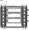
- Figure 1 shows a schematic sectional view of the individual parts of a battery arrangement 10 according to one embodiment of the invention, while Figure 2 depicts the battery arrangement from Figure 1 in a mounted state.
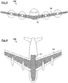
- the battery arrangement 10 serves for structurally integrating batteries 1 in a vehicle, in particular an aircraft 100 (e.g. a passenger aircraft), as can be seen schematically in Figures 5 and 6 .
- the battery arrangement 10 comprises a multiplicity of batteries 1 (for example individual lithium-ion battery cells) which are held between two supporting, multi-layered structural laminates 2 on both sides via battery holders 3.
- the multi-layered structural laminate 2 comprises a core consisting of a cooling plate layer 4 which is surrounded by current collector layers 5 and signal conducting layers 9 which are each separated from one another and from the cooling plate layer 4 via electrical insulating layers 11.
- the cooling plate layers 4 have a multiplicity of fluid ducts 7 which are designed for the passage of a fluid, i.e. a gas and/or a liquid.
- the batteries 1 are coupled electrically here on both sides in each case to a current collector layer 5 and to a signal conducting layer 9.
- the batteries 1 are in contact here via an electrically conductive spring 12 which is in each case arranged on both sides of each battery 1 within a battery receptacle 6 of the battery holder 3.
- the batteries 1 themselves are fastened to the battery holder 3 via an adhesive 19.
- the batteries 1 can be, for example, a known type of lithium-ion secondary battery which is in the form of a round cell and is frequently used, for example, in the electric car sector.
- the battery arrangement 10 comprises two cover plates 8 (which cannot be seen in Figure 1 ) which close off the multi-layered structural laminates 2 with the batteries 1 lying in between.
- the cover plates 8 are fixedly connected here to the multi-layered structural laminate 2 via connecting elements 14, such as screws, rivets, bolts or the like.
- the cover plates 8 can close off a multiplicity of multi-layered structural laminates 2 with batteries 1 lying in between.
- the battery arrangement 10 in Figure 2 can be understood as being a battery module, of which as many as desired can be arranged next to one another, above one another and/or behind one another.
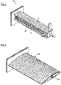
- FIG 3 shows a schematic perspective view of a structural component 15 with one or more of the battery arrangements 10 from Figure 2 .
- a structural component 15 can form part of a wing structure 16, as is illustrated in Figure 4 .
- it can likewise form part of a fuselage structure 17 (cf. Figures 5 and 6 ).
- loads which are in action are identified by arrows, and it is intended as a result to clarify that the battery arrangement 10 itself takes on a supporting structural function.
- the multi-layered structural laminates 2 serve here not only for holding and fixing the batteries 1 in the aircraft 100.
- the multi-layered structural laminates 2 furthermore contribute to the structure of the aircraft 100 as such, with the batteries 1 also being part of the primary structure.
- the load path extends here from the individual batteries 1 or battery cells via the battery holders 3 to the multi-layered structural laminates 2 and from there via the cover plates 8 into the wing structure 16 or fuselage structure 17 of the aircraft 100.
- the battery arrangement 10 can in particular to a certain extent replace and/or supplement existing structures since loads can be conducted through the battery arrangement 10. It is thereby possible to save on further structure-reinforcing components and therefore to save on weight and ultimately fuel and costs.
- the cooling plate layers 4 themselves as a structural core of the multi-layered structural laminates 2 are advantageously manufactured integrally with an additive method from titanium or a titanium alloy, i.e. a highly resistant material having a high strength and relatively low density.
- cooling plate layers 4 including the fluid ducts 7 completely in one process step which would at best be possible with a considerable outlay by conventional methods.
- the cooling plate layers 4 can furthermore be connected to a separate, external heat exchanger (not shown) in order to remove the generated heat or power loss.
- a battery arrangement 10 is thereby therefore integrated structurally in an aircraft 100, wherein multi-layered structural laminates 2 not only carry out structural functions, but furthermore can be used for diverse purposes including the electrical coupling together and control or regulation of the batteries and control of the temperature of the batteries. Furthermore, the multi-layered structural laminate 2, for example in cooperation with the cover plates 8, can serve as a fire protection layer or protective encapsulation of the battery arrangement 10.
Landscapes
- Engineering & Computer Science (AREA)
- Chemical & Material Sciences (AREA)
- Chemical Kinetics & Catalysis (AREA)
- Electrochemistry (AREA)
- General Chemical & Material Sciences (AREA)
- Manufacturing & Machinery (AREA)
- Aviation & Aerospace Engineering (AREA)
- Remote Sensing (AREA)
- Inorganic Chemistry (AREA)
- Mechanical Engineering (AREA)
- Battery Mounting, Suspending (AREA)
- Secondary Cells (AREA)
Claims (9)
- Luftfahrzeug oder Raumfahrzeug (100) mit einem Strukturbauteil (1) mit einer darin integrierten Batterieanordnung (10), wobei die Batterieanordnung (10) umfasst:mindestens eine Batterie (1); undzwei tragende, einstückig verbundene, mehrschichtige Laminate (2), zwischen denen die mindestens eine Batterie (1) beidseitig über Batteriehalter (3) gehalten wird, wobei jedes mehrschichtige Laminat eine Kühlplattenschicht (4) und eine Stromkollektorschicht (5) aufweist, wobei die mindestens eine Batterie (1) elektrisch mit der Stromkollektorschicht (5) gekoppelt ist, wobei die Kühlplattenschicht (4) einstückig mit einer Vielzahl von Fluidkanälen (7) aus einem metallischen Werkstoff hergestellt ist.
- Luft- oder Raumfahrzeug (100) nach Anspruch 1,
wobei die mehrschichtigen Laminate (2) ferner jeweils eine signalleitende Schicht (9) aufweisen, mit der die mindestens eine Batterie (1) elektrisch gekoppelt ist. - Luftfahrzeug oder Raumfahrzeug (100) nach Anspruch 1 oder 2,
wobei die mehrschichtigen Laminate (2) ferner jeweils mindestens eine elektrisch isolierende Schicht (11) aufweisen. - Luftfahrzeug oder Raumfahrzeug (100) nach einem der Ansprüche 1 bis 3,
wobei mindestens eines der mehrschichtigen Laminate (2) eine Vielzahl von Stromabnehmerschichten (5), signalleitenden Schichten (9) und/oder elektrisch isolierenden Schichten (11) aufweist, die beidseitig um die Kühlplattenschicht (4) herum angeordnet sind. - Luft- oder Raumfahrzeug (100) nach einem der Ansprüche 1 bis 4,
wobei die mindestens eine Batterie (1) mindestens auf einer Seite über eine elektrisch leitende Feder (12) mit der Stromkollektorschicht gekoppelt ist. - Luftfahrzeug oder Raumfahrzeug (100) nach einem der Ansprüche 1 bis 5,
wobei die Batteriehalter (3) mit einer Batterieaufnahme (6) zur Aufnahme der mindestens einen Batterie (1) auf einer Seite ausgebildet sind. - Luftfahrzeug oder Raumfahrzeug (100) nach einem der Ansprüche 1 bis 6,
wobei die mindestens eine Batterie (1) an dem Batteriehalter (3) über eine einstückig geklebte Verbindung befestigt ist. - Luftfahrzeug oder Raumfahrzeug (100) nach einem der Ansprüche 1 bis 7, ferner umfassend:
mindestens zwei Deckplatten (8), die die mehrschichtigen Laminate (2) unter Zwischenlage der mindestens einen Batterie (1) verschließen. - Luftfahrzeug oder Raumfahrzeug (100) nach Anspruch 8,
wobei die Deckplatten (8) eine Vielzahl von mehrschichtigen Laminaten (2) mit dazwischen liegenden Batterien (1) verschließen.
Applications Claiming Priority (1)
| Application Number | Priority Date | Filing Date | Title |
|---|---|---|---|
| DE102018202120.1A DE102018202120A1 (de) | 2018-02-12 | 2018-02-12 | Batterieanordnung zur strukturellen Integration von Batterien in ein Fahrzeug |
Publications (2)
| Publication Number | Publication Date |
|---|---|
| EP3525259A1 EP3525259A1 (de) | 2019-08-14 |
| EP3525259B1 true EP3525259B1 (de) | 2020-12-23 |
Family
ID=65411789
Family Applications (1)
| Application Number | Title | Priority Date | Filing Date |
|---|---|---|---|
| EP19156600.9A Active EP3525259B1 (de) | 2018-02-12 | 2019-02-12 | Flugzeug oder raumfahrzeug aufweisend ein tragendes bauteil mit einer darin integrierten batterieanordnung |
Country Status (4)
| Country | Link |
|---|---|
| US (1) | US11302979B2 (de) |
| EP (1) | EP3525259B1 (de) |
| CN (1) | CN110165100A (de) |
| DE (1) | DE102018202120A1 (de) |
Cited By (4)
| Publication number | Priority date | Publication date | Assignee | Title |
|---|---|---|---|---|
| US11217839B2 (en) | 2018-02-12 | 2022-01-04 | Airbus Defence and Space GmbH | Battery arrangement for structurally integrating batteries in a vehicle |
| US11302979B2 (en) | 2018-02-12 | 2022-04-12 | Airbus Defence and Space GmbH | Battery arrangement for the structural integration of batteries in a vehicle |
| US11316224B2 (en) | 2018-03-22 | 2022-04-26 | Airbus Defence and Space GmbH | Battery arrangement for the load-bearing structural integration of batteries into a vehicle |
| EP4611123A1 (de) * | 2024-02-29 | 2025-09-03 | fischer Power Solutions GmbH | Zellträger für mindestens eine elektrische zelle und ein zellmodul mit einem zellträger und einer mehrzahl an elektrischen zellen |
Families Citing this family (23)
| Publication number | Priority date | Publication date | Assignee | Title |
|---|---|---|---|---|
| US10934013B2 (en) * | 2017-09-22 | 2021-03-02 | The Boeing Company | Aircraft fuselage apparatus having embedded structural batteries |
| DE102018116169B4 (de) * | 2018-07-04 | 2022-02-24 | Dr. Ing. H.C. F. Porsche Aktiengesellschaft | Luftfahrzeug |
| US12043126B2 (en) * | 2019-02-21 | 2024-07-23 | The Boeing Company | Structurally integrated energy supply systems for aircraft and methods of forming the structurally integrated energy supply systems |
| EP3813144A1 (de) * | 2019-10-24 | 2021-04-28 | Siemens Aktiengesellschaft | Batteriemodul und verwendung davon |
| NO346251B1 (en) * | 2019-12-11 | 2022-05-09 | Griff Aviation As | An aerial vehicle |
| DE102019220014A1 (de) * | 2019-12-18 | 2021-07-15 | Siemens Aktiengesellschaft | Kühlkörper für eine Batteriezelle, Batteriemodul und Fluggerät |
| KR102163447B1 (ko) * | 2020-05-19 | 2020-10-12 | 김경임 | 배터리 효율이 개선된 드론 |
| KR102729323B1 (ko) * | 2020-06-05 | 2024-11-11 | 삼성에스디아이 주식회사 | 이차 전지 팩 |
| US11685502B2 (en) | 2020-06-30 | 2023-06-27 | Textron Innovations Inc. | Modular hybrid airframe structure for battery thermal event protection and repair |
| CN112018290A (zh) * | 2020-09-04 | 2020-12-01 | 四川长虹电源有限责任公司 | 电池组安装架结构 |
| KR20220066789A (ko) * | 2020-11-16 | 2022-05-24 | 현대모비스 주식회사 | 전기차용 배터리 냉각장치 및 그 제조방법 |
| US12115881B2 (en) | 2021-02-10 | 2024-10-15 | Textron Innovations Inc. | Non-integral battery cold plate |
| US12176506B2 (en) | 2021-02-10 | 2024-12-24 | Textron Innovations Inc. | Battery cold plate and chassis with interlocking joints |
| CN115117497B (zh) * | 2021-03-18 | 2025-04-22 | 辉能科技股份有限公司 | 具散热匣体的电池模块及其电池系统 |
| DE102021116017A1 (de) * | 2021-06-21 | 2022-12-22 | Webasto SE | Batteriemodul zum Aufbau einer Batterie für ein Fahrzeug |
| US11705601B2 (en) | 2021-08-18 | 2023-07-18 | Lockheed Martin Corporation | Structural battery for an aircraft vehicle |
| GB2634659A (en) | 2022-05-13 | 2025-04-16 | Firestorm Labs Inc | Mission-adaptable aerial vehicle and methods for in-field assembly and use |
| CN115520370A (zh) * | 2022-09-22 | 2022-12-27 | 中国商用飞机有限责任公司 | 集成有动力电池模组的机翼系统和电动飞机 |
| WO2024069361A1 (en) * | 2022-09-30 | 2024-04-04 | Bombardier Recreational Products Inc. | Battery pack for an electric vehicle |
| US12591247B2 (en) | 2023-05-08 | 2026-03-31 | Firestorm Labs, Inc. | Unmanned vehicle management system and method |
| DE102023119062A1 (de) | 2023-07-19 | 2025-01-23 | Dr. Ing. H.C. F. Porsche Aktiengesellschaft | Abstandshalter, Batterie, Fahrzeug mit der Batterie, Verfahren zur Herstellung der Batterie |
| WO2025193944A1 (en) | 2024-03-13 | 2025-09-18 | Firestorm Labs, Inc. | Additive manufactured integral fastening system for mission adaptable unmanned aerial vehicles |
| CN120073163B (zh) * | 2025-04-30 | 2025-10-31 | 宁德时代新能源科技股份有限公司 | 电池装置以及用电装置 |
Family Cites Families (34)
| Publication number | Priority date | Publication date | Assignee | Title |
|---|---|---|---|---|
| SE528899C2 (sv) | 2004-11-16 | 2007-03-13 | Saab Automobile | Batterienhet, jämte fordon utrustat med en sådan batterienhet |
| US20100047682A1 (en) | 2007-03-01 | 2010-02-25 | Johnson Controls - SAFT Advanced Power Solutions, LLC | Battery system and thermal management system therefor |
| US20080280198A1 (en) * | 2007-05-07 | 2008-11-13 | Ajith Kuttannair Kumar | Battery mechanical packaging |
| US8845762B2 (en) | 2008-04-09 | 2014-09-30 | GM Global Technology Operations LLC | Batteries and components thereof and methods of making and assembling the same |
| DE102009030016A1 (de) * | 2009-06-23 | 2010-12-30 | Bayerische Motoren Werke Aktiengesellschaft | Vorrichtung zur Spannungsversorung eines Kraftfahrzeugs mit einem Kühlerblock |
| JP2011009402A (ja) * | 2009-06-25 | 2011-01-13 | Panasonic Corp | 蓄電ユニット |
| WO2011094286A2 (en) | 2010-01-26 | 2011-08-04 | Cymbet Corporation | Battery arrays, constructions and method |
| US8383260B2 (en) | 2010-02-26 | 2013-02-26 | GM Global Technology Operations LLC | U-formed cooling plate with solid fins for lithium pouch cells |
| WO2011149868A1 (en) | 2010-05-24 | 2011-12-01 | Parker-Hannifin Corporation | Cooling system and method |
| KR101403779B1 (ko) | 2010-05-26 | 2014-06-03 | 스미도모쥬기가이고교 가부시키가이샤 | 축전모듈을 구비한 쇼벨 |
| US8286743B2 (en) | 2010-12-22 | 2012-10-16 | Tesla Motors, Inc. | Vehicle battery pack ballistic shield |
| US8967529B1 (en) | 2011-03-25 | 2015-03-03 | Odyssian Technology, Llc | Battery-structure |
| DE102011016738A1 (de) | 2011-04-11 | 2012-10-11 | Valeo Klimasysteme Gmbh | Batteriekühlvorrichtung und Batteriebaugruppe |
| DE102012213273B4 (de) | 2012-07-27 | 2021-08-05 | Hydac Technology Gmbh | Energiespeichervorrichtung |
| WO2014125642A1 (ja) | 2013-02-18 | 2014-08-21 | 日立ビークルエナジー株式会社 | 電池ブロック及び二次電池モジュール |
| US9296310B2 (en) | 2014-03-18 | 2016-03-29 | Ford Global Technologies, Llc | Traction battery thermal management system |
| JP2015210894A (ja) * | 2014-04-24 | 2015-11-24 | 株式会社東芝 | 組電池モジュール |
| US9478779B2 (en) | 2014-08-20 | 2016-10-25 | Ford Global Technologies, Llc | Cell to cell terminal connections for a high voltage battery |
| GB2535546B (en) * | 2015-02-18 | 2017-09-20 | Tata Motors European Technical Ct Plc | Battery modules and methods for their manufacture |
| JP6394448B2 (ja) * | 2015-03-16 | 2018-09-26 | 豊田合成株式会社 | 電池モジュールおよびその製造方法 |
| WO2017004078A1 (en) | 2015-06-30 | 2017-01-05 | Faraday&Future Inc. | Vehicle energy-storage systems |
| DE102015214185B4 (de) | 2015-07-27 | 2017-03-30 | Audi Ag | Batteriemodul für ein Kraftfahrzeug, Modulanordnung und Kraftfahrzeug |
| US10622687B2 (en) | 2015-08-10 | 2020-04-14 | Ford Global Technologies, Llc | Battery pack enclosure including integrated fluid channel |
| EP3220444B1 (de) | 2016-03-14 | 2026-04-22 | Miba Battery Systems GmbH | Batterie |
| CN205583100U (zh) | 2016-03-18 | 2016-09-14 | 王建排 | 一种适应于高寒地区模块式电池组 |
| DE102016120838A1 (de) * | 2016-11-02 | 2018-05-03 | E-Seven Systems Technology Management Ltd | Platine zur elektrisch gesicherten Verbindung von Batteriezellen |
| CN205828468U (zh) * | 2016-07-01 | 2016-12-21 | 上海星历新能源科技有限公司 | 圆柱型电池模块的散热结构 |
| DE102016010830A1 (de) | 2016-09-08 | 2017-03-30 | Daimler Ag | Zellblock für eine Kraftfahrzeugbatterie mit einem Abschirmelement zur Abschirmung einer Zellhalterung und/oder einer Batteriezelle |
| CN106240798B (zh) | 2016-09-14 | 2018-05-18 | 北京航空航天大学 | 一种翼梁/储能电池一体化结构 |
| KR102731553B1 (ko) | 2016-12-15 | 2024-11-18 | 현대자동차주식회사 | 냉각 구조가 구비된 배터리 모듈 |
| US11322793B2 (en) * | 2016-12-27 | 2022-05-03 | Panasonic Inteilectual Property Management Co., Ltd. | Battery module |
| DE102018202120A1 (de) | 2018-02-12 | 2019-08-14 | Airbus Defence and Space GmbH | Batterieanordnung zur strukturellen Integration von Batterien in ein Fahrzeug |
| DE102018202114A1 (de) | 2018-02-12 | 2019-08-14 | Airbus Defence and Space GmbH | Batterieanordnung zur strukturellen Integration von Batterien in ein Fahrzeug |
| DE102018204420A1 (de) | 2018-03-22 | 2019-09-26 | Airbus Defence and Space GmbH | Batterieanordnung zur lasttragenden strukturellen Integration von Batterien in ein Fahrzeug |
-
2018
- 2018-02-12 DE DE102018202120.1A patent/DE102018202120A1/de not_active Ceased
-
2019
- 2019-02-11 US US16/272,363 patent/US11302979B2/en active Active
- 2019-02-12 CN CN201910116550.2A patent/CN110165100A/zh active Pending
- 2019-02-12 EP EP19156600.9A patent/EP3525259B1/de active Active
Non-Patent Citations (1)
| Title |
|---|
| None * |
Cited By (4)
| Publication number | Priority date | Publication date | Assignee | Title |
|---|---|---|---|---|
| US11217839B2 (en) | 2018-02-12 | 2022-01-04 | Airbus Defence and Space GmbH | Battery arrangement for structurally integrating batteries in a vehicle |
| US11302979B2 (en) | 2018-02-12 | 2022-04-12 | Airbus Defence and Space GmbH | Battery arrangement for the structural integration of batteries in a vehicle |
| US11316224B2 (en) | 2018-03-22 | 2022-04-26 | Airbus Defence and Space GmbH | Battery arrangement for the load-bearing structural integration of batteries into a vehicle |
| EP4611123A1 (de) * | 2024-02-29 | 2025-09-03 | fischer Power Solutions GmbH | Zellträger für mindestens eine elektrische zelle und ein zellmodul mit einem zellträger und einer mehrzahl an elektrischen zellen |
Also Published As
| Publication number | Publication date |
|---|---|
| CN110165100A (zh) | 2019-08-23 |
| DE102018202120A1 (de) | 2019-08-14 |
| US20190252655A1 (en) | 2019-08-15 |
| EP3525259A1 (de) | 2019-08-14 |
| US11302979B2 (en) | 2022-04-12 |
Similar Documents
| Publication | Publication Date | Title |
|---|---|---|
| US11302979B2 (en) | Battery arrangement for the structural integration of batteries in a vehicle | |
| EP3525257B1 (de) | Batterieanordnung zur strukturellen integration von batterien in einem fahrzeug | |
| US11316224B2 (en) | Battery arrangement for the load-bearing structural integration of batteries into a vehicle | |
| EP4027433B1 (de) | Stromverbrauchsvorrichtung, verfahren zur herstellung einer stromverbrauchsvorrichtung und vorrichtung zur herstellung der stromverbrauchsvorrichtung | |
| US8778528B2 (en) | Electricity storage device | |
| JP6049745B2 (ja) | 中大型電池パックアセンブリ | |
| CN104916797B (zh) | 电池单池的模块承载体和制造模块承载体的方法及电池模块、电池组、电池和电池系统 | |
| US10665914B2 (en) | Battery system housing with integrated cooling pipe | |
| US10396410B2 (en) | Battery system housing with internal busbar | |
| CN207690851U (zh) | 电池包和电动车辆 | |
| US10622686B2 (en) | Battery thermal management system including bimetallic member | |
| EP2983239A1 (de) | Batteriepack für ein automobil mit erhöhter kühlungseffizienz | |
| KR101748645B1 (ko) | 배터리 모듈 | |
| CN207265170U (zh) | 一种电池系统组件压具 | |
| US20170141366A1 (en) | Battery module, electricity storage device, electricity storage system, electronic device, electric-powered vehicle, and power system | |
| CN212113791U (zh) | 一种软包电芯的成组结构电池包 | |
| CN207097904U (zh) | 用于电动汽车的蓄电池组及由其供能的电动汽车 | |
| CN107799683A (zh) | 具有汇流条网格固定的电池系统壳体 | |
| CN207381441U (zh) | 用于电动车的电池组 | |
| JP2013037969A (ja) | 電源装置、車両及び電源装置の製造方法 | |
| CN219498098U (zh) | 电池模组装置、动力电池包及用电设备 | |
| CN218586106U (zh) | 一种液冷板、电池包及用电设备 | |
| CN220189845U (zh) | 具有高散热性能的汇流条和包括该汇流条的电池组 | |
| US20240162556A1 (en) | High-Voltage Accumulator Module Having a Multiplicity of Battery Cells | |
| CN222355280U (zh) | 电池箱体及电池包 |
Legal Events
| Date | Code | Title | Description |
|---|---|---|---|
| PUAI | Public reference made under article 153(3) epc to a published international application that has entered the european phase |
Free format text: ORIGINAL CODE: 0009012 |
|
| STAA | Information on the status of an ep patent application or granted ep patent |
Free format text: STATUS: THE APPLICATION HAS BEEN PUBLISHED |
|
| AK | Designated contracting states |
Kind code of ref document: A1 Designated state(s): AL AT BE BG CH CY CZ DE DK EE ES FI FR GB GR HR HU IE IS IT LI LT LU LV MC MK MT NL NO PL PT RO RS SE SI SK SM TR |
|
| AX | Request for extension of the european patent |
Extension state: BA ME |
|
| STAA | Information on the status of an ep patent application or granted ep patent |
Free format text: STATUS: REQUEST FOR EXAMINATION WAS MADE |
|
| STAA | Information on the status of an ep patent application or granted ep patent |
Free format text: STATUS: EXAMINATION IS IN PROGRESS |
|
| 17P | Request for examination filed |
Effective date: 20200206 |
|
| RBV | Designated contracting states (corrected) |
Designated state(s): AL AT BE BG CH CY CZ DE DK EE ES FI FR GB GR HR HU IE IS IT LI LT LU LV MC MK MT NL NO PL PT RO RS SE SI SK SM TR |
|
| 17Q | First examination report despatched |
Effective date: 20200320 |
|
| GRAP | Despatch of communication of intention to grant a patent |
Free format text: ORIGINAL CODE: EPIDOSNIGR1 |
|
| STAA | Information on the status of an ep patent application or granted ep patent |
Free format text: STATUS: GRANT OF PATENT IS INTENDED |
|
| INTG | Intention to grant announced |
Effective date: 20200716 |
|
| GRAS | Grant fee paid |
Free format text: ORIGINAL CODE: EPIDOSNIGR3 |
|
| GRAA | (expected) grant |
Free format text: ORIGINAL CODE: 0009210 |
|
| STAA | Information on the status of an ep patent application or granted ep patent |
Free format text: STATUS: THE PATENT HAS BEEN GRANTED |
|
| AK | Designated contracting states |
Kind code of ref document: B1 Designated state(s): AL AT BE BG CH CY CZ DE DK EE ES FI FR GB GR HR HU IE IS IT LI LT LU LV MC MK MT NL NO PL PT RO RS SE SI SK SM TR |
|
| REG | Reference to a national code |
Ref country code: GB Ref legal event code: FG4D |
|
| REG | Reference to a national code |
Ref country code: DE Ref legal event code: R096 Ref document number: 602019001804 Country of ref document: DE |
|
| REG | Reference to a national code |
Ref country code: AT Ref legal event code: REF Ref document number: 1348584 Country of ref document: AT Kind code of ref document: T Effective date: 20210115 |
|
| REG | Reference to a national code |
Ref country code: IE Ref legal event code: FG4D |
|
| PG25 | Lapsed in a contracting state [announced via postgrant information from national office to epo] |
Ref country code: GR Free format text: LAPSE BECAUSE OF FAILURE TO SUBMIT A TRANSLATION OF THE DESCRIPTION OR TO PAY THE FEE WITHIN THE PRESCRIBED TIME-LIMIT Effective date: 20210324 Ref country code: NO Free format text: LAPSE BECAUSE OF FAILURE TO SUBMIT A TRANSLATION OF THE DESCRIPTION OR TO PAY THE FEE WITHIN THE PRESCRIBED TIME-LIMIT Effective date: 20210323 Ref country code: FI Free format text: LAPSE BECAUSE OF FAILURE TO SUBMIT A TRANSLATION OF THE DESCRIPTION OR TO PAY THE FEE WITHIN THE PRESCRIBED TIME-LIMIT Effective date: 20201223 Ref country code: RS Free format text: LAPSE BECAUSE OF FAILURE TO SUBMIT A TRANSLATION OF THE DESCRIPTION OR TO PAY THE FEE WITHIN THE PRESCRIBED TIME-LIMIT Effective date: 20201223 |
|
| REG | Reference to a national code |
Ref country code: AT Ref legal event code: MK05 Ref document number: 1348584 Country of ref document: AT Kind code of ref document: T Effective date: 20201223 |
|
| REG | Reference to a national code |
Ref country code: NL Ref legal event code: MP Effective date: 20201223 |
|
| PG25 | Lapsed in a contracting state [announced via postgrant information from national office to epo] |
Ref country code: LV Free format text: LAPSE BECAUSE OF FAILURE TO SUBMIT A TRANSLATION OF THE DESCRIPTION OR TO PAY THE FEE WITHIN THE PRESCRIBED TIME-LIMIT Effective date: 20201223 Ref country code: SE Free format text: LAPSE BECAUSE OF FAILURE TO SUBMIT A TRANSLATION OF THE DESCRIPTION OR TO PAY THE FEE WITHIN THE PRESCRIBED TIME-LIMIT Effective date: 20201223 Ref country code: BG Free format text: LAPSE BECAUSE OF FAILURE TO SUBMIT A TRANSLATION OF THE DESCRIPTION OR TO PAY THE FEE WITHIN THE PRESCRIBED TIME-LIMIT Effective date: 20210323 |
|
| PG25 | Lapsed in a contracting state [announced via postgrant information from national office to epo] |
Ref country code: HR Free format text: LAPSE BECAUSE OF FAILURE TO SUBMIT A TRANSLATION OF THE DESCRIPTION OR TO PAY THE FEE WITHIN THE PRESCRIBED TIME-LIMIT Effective date: 20201223 Ref country code: NL Free format text: LAPSE BECAUSE OF FAILURE TO SUBMIT A TRANSLATION OF THE DESCRIPTION OR TO PAY THE FEE WITHIN THE PRESCRIBED TIME-LIMIT Effective date: 20201223 |
|
| REG | Reference to a national code |
Ref country code: LT Ref legal event code: MG9D |
|
| PG25 | Lapsed in a contracting state [announced via postgrant information from national office to epo] |
Ref country code: LT Free format text: LAPSE BECAUSE OF FAILURE TO SUBMIT A TRANSLATION OF THE DESCRIPTION OR TO PAY THE FEE WITHIN THE PRESCRIBED TIME-LIMIT Effective date: 20201223 Ref country code: PT Free format text: LAPSE BECAUSE OF FAILURE TO SUBMIT A TRANSLATION OF THE DESCRIPTION OR TO PAY THE FEE WITHIN THE PRESCRIBED TIME-LIMIT Effective date: 20210423 Ref country code: RO Free format text: LAPSE BECAUSE OF FAILURE TO SUBMIT A TRANSLATION OF THE DESCRIPTION OR TO PAY THE FEE WITHIN THE PRESCRIBED TIME-LIMIT Effective date: 20201223 Ref country code: CZ Free format text: LAPSE BECAUSE OF FAILURE TO SUBMIT A TRANSLATION OF THE DESCRIPTION OR TO PAY THE FEE WITHIN THE PRESCRIBED TIME-LIMIT Effective date: 20201223 Ref country code: EE Free format text: LAPSE BECAUSE OF FAILURE TO SUBMIT A TRANSLATION OF THE DESCRIPTION OR TO PAY THE FEE WITHIN THE PRESCRIBED TIME-LIMIT Effective date: 20201223 Ref country code: SK Free format text: LAPSE BECAUSE OF FAILURE TO SUBMIT A TRANSLATION OF THE DESCRIPTION OR TO PAY THE FEE WITHIN THE PRESCRIBED TIME-LIMIT Effective date: 20201223 Ref country code: SM Free format text: LAPSE BECAUSE OF FAILURE TO SUBMIT A TRANSLATION OF THE DESCRIPTION OR TO PAY THE FEE WITHIN THE PRESCRIBED TIME-LIMIT Effective date: 20201223 |
|
| PG25 | Lapsed in a contracting state [announced via postgrant information from national office to epo] |
Ref country code: AT Free format text: LAPSE BECAUSE OF FAILURE TO SUBMIT A TRANSLATION OF THE DESCRIPTION OR TO PAY THE FEE WITHIN THE PRESCRIBED TIME-LIMIT Effective date: 20201223 Ref country code: PL Free format text: LAPSE BECAUSE OF FAILURE TO SUBMIT A TRANSLATION OF THE DESCRIPTION OR TO PAY THE FEE WITHIN THE PRESCRIBED TIME-LIMIT Effective date: 20201223 |
|
| REG | Reference to a national code |
Ref country code: DE Ref legal event code: R097 Ref document number: 602019001804 Country of ref document: DE |
|
| PG25 | Lapsed in a contracting state [announced via postgrant information from national office to epo] |
Ref country code: MC Free format text: LAPSE BECAUSE OF FAILURE TO SUBMIT A TRANSLATION OF THE DESCRIPTION OR TO PAY THE FEE WITHIN THE PRESCRIBED TIME-LIMIT Effective date: 20201223 Ref country code: IS Free format text: LAPSE BECAUSE OF FAILURE TO SUBMIT A TRANSLATION OF THE DESCRIPTION OR TO PAY THE FEE WITHIN THE PRESCRIBED TIME-LIMIT Effective date: 20210423 |
|
| REG | Reference to a national code |
Ref country code: BE Ref legal event code: MM Effective date: 20210228 |
|
| PG25 | Lapsed in a contracting state [announced via postgrant information from national office to epo] |
Ref country code: IT Free format text: LAPSE BECAUSE OF FAILURE TO SUBMIT A TRANSLATION OF THE DESCRIPTION OR TO PAY THE FEE WITHIN THE PRESCRIBED TIME-LIMIT Effective date: 20201223 Ref country code: LU Free format text: LAPSE BECAUSE OF NON-PAYMENT OF DUE FEES Effective date: 20210212 Ref country code: AL Free format text: LAPSE BECAUSE OF FAILURE TO SUBMIT A TRANSLATION OF THE DESCRIPTION OR TO PAY THE FEE WITHIN THE PRESCRIBED TIME-LIMIT Effective date: 20201223 |
|
| PLBE | No opposition filed within time limit |
Free format text: ORIGINAL CODE: 0009261 |
|
| STAA | Information on the status of an ep patent application or granted ep patent |
Free format text: STATUS: NO OPPOSITION FILED WITHIN TIME LIMIT |
|
| PG25 | Lapsed in a contracting state [announced via postgrant information from national office to epo] |
Ref country code: DK Free format text: LAPSE BECAUSE OF FAILURE TO SUBMIT A TRANSLATION OF THE DESCRIPTION OR TO PAY THE FEE WITHIN THE PRESCRIBED TIME-LIMIT Effective date: 20201223 |
|
| 26N | No opposition filed |
Effective date: 20210924 |
|
| PG25 | Lapsed in a contracting state [announced via postgrant information from national office to epo] |
Ref country code: IE Free format text: LAPSE BECAUSE OF NON-PAYMENT OF DUE FEES Effective date: 20210212 Ref country code: ES Free format text: LAPSE BECAUSE OF FAILURE TO SUBMIT A TRANSLATION OF THE DESCRIPTION OR TO PAY THE FEE WITHIN THE PRESCRIBED TIME-LIMIT Effective date: 20201223 |
|
| PG25 | Lapsed in a contracting state [announced via postgrant information from national office to epo] |
Ref country code: SI Free format text: LAPSE BECAUSE OF FAILURE TO SUBMIT A TRANSLATION OF THE DESCRIPTION OR TO PAY THE FEE WITHIN THE PRESCRIBED TIME-LIMIT Effective date: 20201223 |
|
| PG25 | Lapsed in a contracting state [announced via postgrant information from national office to epo] |
Ref country code: IS Free format text: LAPSE BECAUSE OF FAILURE TO SUBMIT A TRANSLATION OF THE DESCRIPTION OR TO PAY THE FEE WITHIN THE PRESCRIBED TIME-LIMIT Effective date: 20210423 |
|
| PG25 | Lapsed in a contracting state [announced via postgrant information from national office to epo] |
Ref country code: BE Free format text: LAPSE BECAUSE OF NON-PAYMENT OF DUE FEES Effective date: 20210228 |
|
| REG | Reference to a national code |
Ref country code: CH Ref legal event code: PL |
|
| PG25 | Lapsed in a contracting state [announced via postgrant information from national office to epo] |
Ref country code: LI Free format text: LAPSE BECAUSE OF NON-PAYMENT OF DUE FEES Effective date: 20220228 Ref country code: CH Free format text: LAPSE BECAUSE OF NON-PAYMENT OF DUE FEES Effective date: 20220228 |
|
| PG25 | Lapsed in a contracting state [announced via postgrant information from national office to epo] |
Ref country code: CY Free format text: LAPSE BECAUSE OF FAILURE TO SUBMIT A TRANSLATION OF THE DESCRIPTION OR TO PAY THE FEE WITHIN THE PRESCRIBED TIME-LIMIT Effective date: 20201223 |
|
| PG25 | Lapsed in a contracting state [announced via postgrant information from national office to epo] |
Ref country code: HU Free format text: LAPSE BECAUSE OF FAILURE TO SUBMIT A TRANSLATION OF THE DESCRIPTION OR TO PAY THE FEE WITHIN THE PRESCRIBED TIME-LIMIT; INVALID AB INITIO Effective date: 20190212 |
|
| PG25 | Lapsed in a contracting state [announced via postgrant information from national office to epo] |
Ref country code: MK Free format text: LAPSE BECAUSE OF FAILURE TO SUBMIT A TRANSLATION OF THE DESCRIPTION OR TO PAY THE FEE WITHIN THE PRESCRIBED TIME-LIMIT Effective date: 20201223 |
|
| PG25 | Lapsed in a contracting state [announced via postgrant information from national office to epo] |
Ref country code: TR Free format text: LAPSE BECAUSE OF FAILURE TO SUBMIT A TRANSLATION OF THE DESCRIPTION OR TO PAY THE FEE WITHIN THE PRESCRIBED TIME-LIMIT Effective date: 20201223 |
|
| PG25 | Lapsed in a contracting state [announced via postgrant information from national office to epo] |
Ref country code: MT Free format text: LAPSE BECAUSE OF FAILURE TO SUBMIT A TRANSLATION OF THE DESCRIPTION OR TO PAY THE FEE WITHIN THE PRESCRIBED TIME-LIMIT Effective date: 20201223 |
|
| PGFP | Annual fee paid to national office [announced via postgrant information from national office to epo] |
Ref country code: GB Payment date: 20260219 Year of fee payment: 8 |
|
| PGFP | Annual fee paid to national office [announced via postgrant information from national office to epo] |
Ref country code: DE Payment date: 20260218 Year of fee payment: 8 |
|
| PGFP | Annual fee paid to national office [announced via postgrant information from national office to epo] |
Ref country code: FR Payment date: 20260218 Year of fee payment: 8 |