EP3525257A1 - Battery arrangement for structurally integrating batteries in a vehicle - Google Patents
Battery arrangement for structurally integrating batteries in a vehicle Download PDFInfo
- Publication number
- EP3525257A1 EP3525257A1 EP19155733.9A EP19155733A EP3525257A1 EP 3525257 A1 EP3525257 A1 EP 3525257A1 EP 19155733 A EP19155733 A EP 19155733A EP 3525257 A1 EP3525257 A1 EP 3525257A1
- Authority
- EP
- European Patent Office
- Prior art keywords
- battery
- cooling plates
- arrangement
- batteries
- battery arrangement
- Prior art date
- Legal status (The legal status is an assumption and is not a legal conclusion. Google has not performed a legal analysis and makes no representation as to the accuracy of the status listed.)
- Granted
Links
Images


Classifications
-
- H—ELECTRICITY
- H01—ELECTRIC ELEMENTS
- H01M—PROCESSES OR MEANS, e.g. BATTERIES, FOR THE DIRECT CONVERSION OF CHEMICAL ENERGY INTO ELECTRICAL ENERGY
- H01M10/00—Secondary cells; Manufacture thereof
- H01M10/60—Heating or cooling; Temperature control
- H01M10/65—Means for temperature control structurally associated with the cells
- H01M10/655—Solid structures for heat exchange or heat conduction
- H01M10/6556—Solid parts with flow channel passages or pipes for heat exchange
-
- B—PERFORMING OPERATIONS; TRANSPORTING
- B60—VEHICLES IN GENERAL
- B60L—PROPULSION OF ELECTRICALLY-PROPELLED VEHICLES; SUPPLYING ELECTRIC POWER FOR AUXILIARY EQUIPMENT OF ELECTRICALLY-PROPELLED VEHICLES; ELECTRODYNAMIC BRAKE SYSTEMS FOR VEHICLES IN GENERAL; MAGNETIC SUSPENSION OR LEVITATION FOR VEHICLES; MONITORING OPERATING VARIABLES OF ELECTRICALLY-PROPELLED VEHICLES; ELECTRIC SAFETY DEVICES FOR ELECTRICALLY-PROPELLED VEHICLES
- B60L50/00—Electric propulsion with power supplied within the vehicle
- B60L50/50—Electric propulsion with power supplied within the vehicle using propulsion power supplied by batteries or fuel cells
- B60L50/60—Electric propulsion with power supplied within the vehicle using propulsion power supplied by batteries or fuel cells using power supplied by batteries
- B60L50/66—Arrangements of batteries
-
- B—PERFORMING OPERATIONS; TRANSPORTING
- B64—AIRCRAFT; AVIATION; COSMONAUTICS
- B64D—EQUIPMENT FOR FITTING IN OR TO AIRCRAFT; FLIGHT SUITS; PARACHUTES; ARRANGEMENT OR MOUNTING OF POWER PLANTS OR PROPULSION TRANSMISSIONS IN AIRCRAFT
- B64D27/00—Arrangement or mounting of power plants in aircraft; Aircraft characterised by the type or position of power plants
- B64D27/02—Aircraft characterised by the type or position of power plants
- B64D27/30—Aircraft characterised by electric power plants
- B64D27/35—Arrangements for on-board electric energy production, distribution, recovery or storage
- B64D27/357—Arrangements for on-board electric energy production, distribution, recovery or storage using batteries
-
- B—PERFORMING OPERATIONS; TRANSPORTING
- B64—AIRCRAFT; AVIATION; COSMONAUTICS
- B64D—EQUIPMENT FOR FITTING IN OR TO AIRCRAFT; FLIGHT SUITS; PARACHUTES; ARRANGEMENT OR MOUNTING OF POWER PLANTS OR PROPULSION TRANSMISSIONS IN AIRCRAFT
- B64D27/00—Arrangement or mounting of power plants in aircraft; Aircraft characterised by the type or position of power plants
- B64D27/40—Arrangements for mounting power plants in aircraft
-
- B—PERFORMING OPERATIONS; TRANSPORTING
- B64—AIRCRAFT; AVIATION; COSMONAUTICS
- B64D—EQUIPMENT FOR FITTING IN OR TO AIRCRAFT; FLIGHT SUITS; PARACHUTES; ARRANGEMENT OR MOUNTING OF POWER PLANTS OR PROPULSION TRANSMISSIONS IN AIRCRAFT
- B64D33/00—Arrangement in aircraft of power plant parts or auxiliaries not otherwise provided for
- B64D33/08—Arrangement in aircraft of power plant parts or auxiliaries not otherwise provided for of power plant cooling systems
-
- B—PERFORMING OPERATIONS; TRANSPORTING
- B64—AIRCRAFT; AVIATION; COSMONAUTICS
- B64G—COSMONAUTICS; VEHICLES OR EQUIPMENT THEREFOR
- B64G1/00—Cosmonautic vehicles
- B64G1/22—Parts of, or equipment specially adapted for fitting in or to, cosmonautic vehicles
- B64G1/42—Arrangements or adaptations of power supply systems
- B64G1/425—Power storage
-
- B—PERFORMING OPERATIONS; TRANSPORTING
- B64—AIRCRAFT; AVIATION; COSMONAUTICS
- B64G—COSMONAUTICS; VEHICLES OR EQUIPMENT THEREFOR
- B64G1/00—Cosmonautic vehicles
- B64G1/22—Parts of, or equipment specially adapted for fitting in or to, cosmonautic vehicles
- B64G1/46—Arrangements or adaptations of devices for control of environment or living conditions
- B64G1/50—Arrangements or adaptations of devices for control of environment or living conditions for temperature control
-
- H—ELECTRICITY
- H01—ELECTRIC ELEMENTS
- H01M—PROCESSES OR MEANS, e.g. BATTERIES, FOR THE DIRECT CONVERSION OF CHEMICAL ENERGY INTO ELECTRICAL ENERGY
- H01M10/00—Secondary cells; Manufacture thereof
- H01M10/60—Heating or cooling; Temperature control
- H01M10/61—Types of temperature control
- H01M10/613—Cooling or keeping cold
-
- H—ELECTRICITY
- H01—ELECTRIC ELEMENTS
- H01M—PROCESSES OR MEANS, e.g. BATTERIES, FOR THE DIRECT CONVERSION OF CHEMICAL ENERGY INTO ELECTRICAL ENERGY
- H01M10/00—Secondary cells; Manufacture thereof
- H01M10/60—Heating or cooling; Temperature control
- H01M10/62—Heating or cooling; Temperature control specially adapted for specific applications
-
- H—ELECTRICITY
- H01—ELECTRIC ELEMENTS
- H01M—PROCESSES OR MEANS, e.g. BATTERIES, FOR THE DIRECT CONVERSION OF CHEMICAL ENERGY INTO ELECTRICAL ENERGY
- H01M10/00—Secondary cells; Manufacture thereof
- H01M10/60—Heating or cooling; Temperature control
- H01M10/62—Heating or cooling; Temperature control specially adapted for specific applications
- H01M10/625—Vehicles
-
- H—ELECTRICITY
- H01—ELECTRIC ELEMENTS
- H01M—PROCESSES OR MEANS, e.g. BATTERIES, FOR THE DIRECT CONVERSION OF CHEMICAL ENERGY INTO ELECTRICAL ENERGY
- H01M10/00—Secondary cells; Manufacture thereof
- H01M10/60—Heating or cooling; Temperature control
- H01M10/64—Heating or cooling; Temperature control characterised by the shape of the cells
- H01M10/643—Cylindrical cells
-
- H—ELECTRICITY
- H01—ELECTRIC ELEMENTS
- H01M—PROCESSES OR MEANS, e.g. BATTERIES, FOR THE DIRECT CONVERSION OF CHEMICAL ENERGY INTO ELECTRICAL ENERGY
- H01M10/00—Secondary cells; Manufacture thereof
- H01M10/60—Heating or cooling; Temperature control
- H01M10/65—Means for temperature control structurally associated with the cells
- H01M10/655—Solid structures for heat exchange or heat conduction
- H01M10/6551—Surfaces specially adapted for heat dissipation or radiation, e.g. fins or coatings
-
- H—ELECTRICITY
- H01—ELECTRIC ELEMENTS
- H01M—PROCESSES OR MEANS, e.g. BATTERIES, FOR THE DIRECT CONVERSION OF CHEMICAL ENERGY INTO ELECTRICAL ENERGY
- H01M10/00—Secondary cells; Manufacture thereof
- H01M10/60—Heating or cooling; Temperature control
- H01M10/65—Means for temperature control structurally associated with the cells
- H01M10/655—Solid structures for heat exchange or heat conduction
- H01M10/6554—Rods or plates
-
- H—ELECTRICITY
- H01—ELECTRIC ELEMENTS
- H01M—PROCESSES OR MEANS, e.g. BATTERIES, FOR THE DIRECT CONVERSION OF CHEMICAL ENERGY INTO ELECTRICAL ENERGY
- H01M10/00—Secondary cells; Manufacture thereof
- H01M10/60—Heating or cooling; Temperature control
- H01M10/65—Means for temperature control structurally associated with the cells
- H01M10/655—Solid structures for heat exchange or heat conduction
- H01M10/6554—Rods or plates
- H01M10/6555—Rods or plates arranged between the cells
-
- H—ELECTRICITY
- H01—ELECTRIC ELEMENTS
- H01M—PROCESSES OR MEANS, e.g. BATTERIES, FOR THE DIRECT CONVERSION OF CHEMICAL ENERGY INTO ELECTRICAL ENERGY
- H01M10/00—Secondary cells; Manufacture thereof
- H01M10/60—Heating or cooling; Temperature control
- H01M10/65—Means for temperature control structurally associated with the cells
- H01M10/656—Means for temperature control structurally associated with the cells characterised by the type of heat-exchange fluid
- H01M10/6561—Gases
- H01M10/6562—Gases with free flow by convection only
-
- H—ELECTRICITY
- H01—ELECTRIC ELEMENTS
- H01M—PROCESSES OR MEANS, e.g. BATTERIES, FOR THE DIRECT CONVERSION OF CHEMICAL ENERGY INTO ELECTRICAL ENERGY
- H01M50/00—Constructional details or processes of manufacture of the non-active parts of electrochemical cells other than fuel cells, e.g. hybrid cells
- H01M50/20—Mountings; Secondary casings or frames; Racks, modules or packs; Suspension devices; Shock absorbers; Transport or carrying devices; Holders
- H01M50/204—Racks, modules or packs for multiple batteries or multiple cells
-
- H—ELECTRICITY
- H01—ELECTRIC ELEMENTS
- H01M—PROCESSES OR MEANS, e.g. BATTERIES, FOR THE DIRECT CONVERSION OF CHEMICAL ENERGY INTO ELECTRICAL ENERGY
- H01M50/00—Constructional details or processes of manufacture of the non-active parts of electrochemical cells other than fuel cells, e.g. hybrid cells
- H01M50/20—Mountings; Secondary casings or frames; Racks, modules or packs; Suspension devices; Shock absorbers; Transport or carrying devices; Holders
- H01M50/249—Mountings; Secondary casings or frames; Racks, modules or packs; Suspension devices; Shock absorbers; Transport or carrying devices; Holders specially adapted for aircraft or vehicles, e.g. cars or trains
-
- H—ELECTRICITY
- H01—ELECTRIC ELEMENTS
- H01M—PROCESSES OR MEANS, e.g. BATTERIES, FOR THE DIRECT CONVERSION OF CHEMICAL ENERGY INTO ELECTRICAL ENERGY
- H01M50/00—Constructional details or processes of manufacture of the non-active parts of electrochemical cells other than fuel cells, e.g. hybrid cells
- H01M50/50—Current conducting connections for cells or batteries
- H01M50/502—Interconnectors for connecting terminals of adjacent batteries; Interconnectors for connecting cells outside a battery casing
- H01M50/521—Interconnectors for connecting terminals of adjacent batteries; Interconnectors for connecting cells outside a battery casing characterised by the material
- H01M50/522—Inorganic material
-
- B—PERFORMING OPERATIONS; TRANSPORTING
- B60—VEHICLES IN GENERAL
- B60L—PROPULSION OF ELECTRICALLY-PROPELLED VEHICLES; SUPPLYING ELECTRIC POWER FOR AUXILIARY EQUIPMENT OF ELECTRICALLY-PROPELLED VEHICLES; ELECTRODYNAMIC BRAKE SYSTEMS FOR VEHICLES IN GENERAL; MAGNETIC SUSPENSION OR LEVITATION FOR VEHICLES; MONITORING OPERATING VARIABLES OF ELECTRICALLY-PROPELLED VEHICLES; ELECTRIC SAFETY DEVICES FOR ELECTRICALLY-PROPELLED VEHICLES
- B60L2200/00—Type of vehicles
- B60L2200/10—Air crafts
-
- B—PERFORMING OPERATIONS; TRANSPORTING
- B60—VEHICLES IN GENERAL
- B60Y—INDEXING SCHEME RELATING TO ASPECTS CROSS-CUTTING VEHICLE TECHNOLOGY
- B60Y2200/00—Type of vehicle
- B60Y2200/90—Vehicles comprising electric prime movers
- B60Y2200/91—Electric vehicles
-
- B—PERFORMING OPERATIONS; TRANSPORTING
- B60—VEHICLES IN GENERAL
- B60Y—INDEXING SCHEME RELATING TO ASPECTS CROSS-CUTTING VEHICLE TECHNOLOGY
- B60Y2200/00—Type of vehicle
- B60Y2200/90—Vehicles comprising electric prime movers
- B60Y2200/92—Hybrid vehicles
-
- H—ELECTRICITY
- H01—ELECTRIC ELEMENTS
- H01M—PROCESSES OR MEANS, e.g. BATTERIES, FOR THE DIRECT CONVERSION OF CHEMICAL ENERGY INTO ELECTRICAL ENERGY
- H01M2220/00—Batteries for particular applications
- H01M2220/20—Batteries in motive systems, e.g. vehicle, ship, plane
-
- Y—GENERAL TAGGING OF NEW TECHNOLOGICAL DEVELOPMENTS; GENERAL TAGGING OF CROSS-SECTIONAL TECHNOLOGIES SPANNING OVER SEVERAL SECTIONS OF THE IPC; TECHNICAL SUBJECTS COVERED BY FORMER USPC CROSS-REFERENCE ART COLLECTIONS [XRACs] AND DIGESTS
- Y02—TECHNOLOGIES OR APPLICATIONS FOR MITIGATION OR ADAPTATION AGAINST CLIMATE CHANGE
- Y02E—REDUCTION OF GREENHOUSE GAS [GHG] EMISSIONS, RELATED TO ENERGY GENERATION, TRANSMISSION OR DISTRIBUTION
- Y02E60/00—Enabling technologies; Technologies with a potential or indirect contribution to GHG emissions mitigation
- Y02E60/10—Energy storage using batteries
-
- Y—GENERAL TAGGING OF NEW TECHNOLOGICAL DEVELOPMENTS; GENERAL TAGGING OF CROSS-SECTIONAL TECHNOLOGIES SPANNING OVER SEVERAL SECTIONS OF THE IPC; TECHNICAL SUBJECTS COVERED BY FORMER USPC CROSS-REFERENCE ART COLLECTIONS [XRACs] AND DIGESTS
- Y02—TECHNOLOGIES OR APPLICATIONS FOR MITIGATION OR ADAPTATION AGAINST CLIMATE CHANGE
- Y02T—CLIMATE CHANGE MITIGATION TECHNOLOGIES RELATED TO TRANSPORTATION
- Y02T10/00—Road transport of goods or passengers
- Y02T10/60—Other road transportation technologies with climate change mitigation effect
- Y02T10/70—Energy storage systems for electromobility, e.g. batteries
Definitions
- the present invention relates to a battery arrangement for structurally integrating batteries in a vehicle, in particular an aircraft or spacecraft.
- Lithium ion rechargeable batteries can be found as rechargeable energy stores in a wide variety of fields of technology. In particular, they are used as energy stores for electric cars and hybrid vehicles in electric mobility. For this purpose, many manufacturers implement a multiplicity of batteries or battery cells in the form of so-called battery packs in a vehicle structure, for example a motor vehicle body. Several thousand individual cells may be connected to one another in such a battery pack or battery set, for example lithium ion round cells having a cylinder diameter of approximately 20 mm and a length of approximately 100 mm.
- the present invention is based on the object of finding solutions for integrating a large number of battery cells in a vehicle in an efficient and lightweight manner.
- this object is achieved by means of a battery arrangement having the features of Patent Claim 1 and by means of an aircraft or spacecraft having the features of Patent Claim 12.
- the battery arrangement comprises at least one battery; two supporting cooling plates between which the at least one battery is held on both sides via battery holders; and a plurality of connecting rods which connect the two cooling plates to one another.
- An aircraft and spacecraft having a battery arrangement according to the invention are also provided.
- cooling plates are used to control the temperature of the batteries, that is to say to dissipate the heat produced by the batteries, in particular.
- the cooling plates according to the invention are used as structural components and in this manner contribute to the structural integrity of the battery arrangement or the vehicle.
- the battery arrangement according to the invention and therefore the batteries themselves are carried by two cooling plates for this purpose.
- Additional connecting rods are used to reinforce the arrangement with respect to tensile stresses.
- compressive and shear forces can also be directly conducted through the at least one battery or battery cell, that is to say the at least one battery can assume at least some of the loads.
- a battery in the sense of the invention is a general rechargeable electrical storage element. This may be a secondary cell, that is to say an individual storage element in the sense of a secondary element, a rechargeable battery cell, a battery cell or the like. In principle, however, batteries according to the invention likewise comprise interconnected secondary cells and/or interconnected storage elements, that is to say a battery comprising secondary cells. Batteries in the sense of the invention comprise lithium ion rechargeable batteries, in particular. The battery holders can be designed, in particular, to accommodate cylindrical batteries or battery cells.
- one cooling plate can be connected to one battery holder in each case via shear pins.
- the shear pins are used, inter alia, to absorb shear forces which act on the batteries or the cooling plates.
- the battery holders can be connected to the cooling plate in another manner, for example using an integral material connection such as an adhesive or welded connection.
- the shear pins may contain a plastic material.
- the shear pins may be produced from a plastic material. Selecting a plastic material makes it possible to save weight in comparison with a variant having a metal material. Since the shear forces which occur in many applications are considerably lower than, for example, the tensile and/or compressive forces acting on the battery arrangement, a plastic material provides a weight-efficient solution. Furthermore, electrical short circuits with the electrical connections of the at least one battery are excluded in this manner.
- the at least one battery can be mounted on both sides in the battery holders in a form-fitting manner.
- the battery holders may be produced from a plastic.
- a form-fitting connection avoids tolerances to the greatest possible extent.
- the batteries may be coupled on one side or on two sides to the current collector via an electrically conductive spring without the battery having to be connected to said current collector in another manner, for example using a welded connection, as is conventionally customary.
- a spring automatically compensates for tolerances.
- the at least one battery may be fastened to the battery holder using a thermally conductive adhesive, for example.
- mechanical holders and/or plug-in, click and/or snap mechanisms or the like are likewise provided for the purpose of fastening the at least one battery.
- the battery holders may be in the form of plates having a battery receptacle for accommodating the at least one battery on one side.
- each battery holder can be releasably or non-releasably fastened to the corresponding cooling plate, for example via an adhesive connection and/or a screw, plug-in or rivet connection or the like.
- the at least one battery can be initially introduced into the battery holder of one cooling plate on one side and fastened.
- the battery holder of the second cooling plate can be attached and can be plugged together with the structure in such a manner that the other side of the at least one battery is introduced into the further battery holder.
- two current collectors may also be provided, to which the at least one battery is respectively electrically coupled on both sides.
- a bus bar for example a copper rail, to which the battery holder can in turn be adhesively bonded (the battery holder may have a plastic and/or may be produced from a plastic, for example), can be respectively applied to each cooling plate.
- the battery holders may also have battery receptacles which are designed with a through-hole or a passage opening to the corresponding current collector.
- the at least one battery can be welded to the bus bar in the conventional manner, for example, or can be electrically coupled to the bus bar in another manner.
- an electrical insulation layer may also be applied to the cooling plate under the current collector.
- the specific electrical wiring and connection of the batteries can be carried out in any desired manner familiar to a person skilled in the art, for example as a serial and/or parallel circuit.
- the cooling plates can be integrally produced from a metal material having a multiplicity of fluid channels.
- the battery holders can be formed from a plastic or from another lightweight material for the purpose of reducing weight.
- the cooling plate may be produced from a metal, a metal alloy, a metal material and/or a combination of these materials.
- the cooling plate is produced from titanium.
- the cooling plates it is possible to use, for example, an additive method in which the cooling plates are completely produced in an integral manner without the need for special effort, additional mounting steps or even manual work.
- the cooling plates can be produced from all materials or material combinations for which additive methods are known.
- 3-D printing methods In generative or additive production methods, also generally referred to as “3-D printing methods", one or more starting materials are sequentially layered above one another in layers, starting from a digitized geometrical model of an object, and are hardened.
- SLM selective laser melting
- a component is constructed in layers from a modelling material, for example a plastic or a metal, by applying the modelling material in powder form to a substrate and liquefying it in a targeted manner by means of local laser radiation, thus resulting in a solid cohesive component after cooling.
- 3-D printing provides extraordinary design freedom and allows, inter alia, objects, which could not be produced using conventional methods or could be produced only with considerable effort, to be produced with reasonable effort. For this reason, 3-D printing methods are currently widespread in industrial design, in the automotive industry, the aviation and aerospace industries or generally in industrial product development in which a resource-efficient process chain is used for the appropriate small-scale and large-scale production of individualized components.
- 3-D printing methods are particularly advantageous in the present case since they make it possible to produce three-dimensional components in casting methods without requiring special production tools matched to the outer shape of the components. This enables highly efficient, material-saving and time-saving production processes for parts and components.
- Such 3-D printing methods are particularly advantageous in the aviation and aerospace sectors since very many different components which are matched to specific intended purposes are used there and can be produced in such 3-D printing methods at low cost, with a short production lead time and with little complexity in the production installations required for production.
- 3-D printing methods in the sense of the present application comprise all generative or additive production methods in which objects of a predefined shape are produced on the basis of geometrical models from shapeless materials such as liquids and powders or neutrally shaped semifinished products, for instance material in the form of tape or wire, by means of chemical and/or physical processes in a special generative production system.
- 3-D printing methods in the sense of the present application use additive processes in this case in which the starting material is sequentially constructed in layers in predefined shapes.
- the connecting rods can contain a metal material.
- the connecting rods may be produced from a metal material.
- the connecting rods may contain and/or be produced from a metal, a metal alloy, a metal material and/or a combination of these materials. In this manner, the connecting rods can accordingly have a robust design for absorbing relatively large tensile and/or compressive loads.
- At least two side walls may also be provided, which close off the cooling plates with the at least one battery in between.
- the side walls may be produced, for example, from a plastic, a ceramic material, a metal material or a combination of these materials.
- the side walls can therefore form, to some extent, a housing of the battery arrangement in interaction with the cooling plates, but at least the cooling plates also undertake structural tasks.
- At least one of the side walls may be in the form of a heat exchanger having a multiplicity of cooling ribs.
- a design of the corresponding side wall(s) from a metal material is appropriate, in particular.
- the cooling ribs are particularly advantageous for dissipating heat produced by the batteries to the outside.
- the side walls may close off a multiplicity of cooling plates with batteries in between.
- a set of two cooling plates with the batteries held in between can be respectively interpreted as a battery module.
- a multiplicity of such battery modules can be combined with one another in order to form a battery set having a large number of individual cells.
- the multiplicity of battery modules can be closed off by the side walls.
- the battery arrangement can be coupled to the aircraft or spacecraft via at least two side walls which close off the cooling plates with the at least one battery in between.
- the side walls may have fastening points and/or devices for coupling to the vehicle, for example lugs, holes etc.
- the side walls are therefore used as mounting interfaces to the corresponding vehicle.
- the load path therefore extends from the individual batteries or battery cells, via the battery holders, to the cooling plates and, from there, to the vehicle via the side walls.
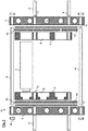
- Figure 1 shows a schematic sectional view of the individual parts of a battery arrangement 10 according to one embodiment of the invention, whereas Figs. 2 and 3 depict the battery arrangement from Fig. 1 in the mounted state ( Fig. 3 shows only an individual battery in a simplifying manner).
- the battery arrangement 10 is used to structurally integrate batteries 1 in a vehicle, in particular an aircraft 100 (for example a passenger aircraft), as can be schematically seen in Fig. 6 .
- the battery arrangement 10 comprises a multiplicity of batteries 1 (for example individual lithium ion battery cells) which are held between two supporting cooling plates 2 on both sides via battery holders 3.
- the cooling plates 2 have a multiplicity of fluid channels 7 which are designed to conduct a fluid, that is to say a gas and/or a liquid.
- the battery arrangement 10 also comprises a plurality of connecting rods 4, which connect the two cooling plates 2 to one another, and a plurality of shear pins 5 which couple the cooling plates 2 to the battery holders 3.
- the cooling plates 2 and the battery holders 3 have accordingly designed through-holes 13, through which the pins or rods can be passed.
- the connecting rods 4 and/or shear pins 5 can be adhesively bonded to the cooling plates 2 or battery holders 3 using an adhesive.
- the connecting rods 4 and/or shear pins 5 may have external threads onto which fastening nuts 14 can be screwed, for example.
- the through-holes 13 may comprise corresponding internal threads.
- the battery holders 3 can be additionally adhesively bonded to the cooling plates 2.
- the cooling plates 2 are used as supporting structural components which not only hold and fix the batteries 1 in the aircraft 100 but are also used to structurally reinforce the aircraft 100 as such. Stability with respect to tensile or compressive forces and shear forces is achieved in this case by means of the connecting rods 4 and the shear pins 5 which connect the cooling plates 2 to one another and to the battery holders 3.
- the cooling plates 2 are advantageously integrally produced from titanium or a titanium alloy using an additive method, that is to say a highly stable material with a high strength with a relatively low density.
- 3-D printing methods make it possible to produce the cooling plates 2, including the through-holes 13 and the fluid channels 7, completely in one process step, which would be possible at best with considerable effort using conventional methods.
- the connecting rods 4 are likewise formed from a metal material, for example likewise titanium or a titanium alloy.
- a plastic material is provided for the shear pins 5 in this exemplary embodiment, for the purpose of minimizing weight.
- the battery holders 3 also have battery receptacles 6 which accommodate each of the individual batteries 1 with an accurate fit.
- the battery receptacles 6 may be cylindrical, for example, for accommodating one or more cylindrical batteries 1.
- the batteries 1 may be, for example, a known type of lithium ion secondary battery which is in the form of a round cell and is often used in the field of electric cars, for example.
- each battery 1 can be fastened in the battery receptacle 6, for example using a thermally conductive adhesive or a mechanical holder.
- a current collector 12, for example a bus bar such as a copper rail or the like, is respectively arranged between each battery holder 3 and the respective cooling plate 2, with the result that the respective battery 1 can be electrically coupled inside the battery receptacle 6.
- the batteries can be welded to the bus bar, for example.
- an insulation layer 11 is also provided between the corresponding cooling plate and the current collector 12.
- the battery holders 3 may be produced in the form of plates from a material having a high thermal conductivity.
- the cooling plates 2 are not only used to cool or control the temperature of the batteries 1.
- the batteries 1 are fixed via the cooling plates 2.
- the cooling plates 2 are structural components having supporting or reinforcing functions and are therefore multifunctional. This makes it possible to save advanced structure-reinforcing components and therefore weight and ultimately fuel.
- the cooling plates 2 can also be connected to a separate, external heat exchanger (not depicted) in order to dissipate the heat or power loss produced.
- Fig. 4 shows a schematic perspective view of the battery arrangement 10 from Figs. 2 and 3 with two additional side walls 8.
- the two side walls 8 enclose the cooling plates 2 with the batteries 1 in between in a housing-like manner and are also used to mount or couple the battery arrangement 10 inside the aircraft 100.
- the side walls 8 have (fastening) lugs 15.
- the side walls 8 are also at least partially designed with cooling ribs 9 for the purpose of dissipating the heat produced by the batteries 1.
- the side walls 8 may also be produced from a metal material, for example titanium.
- Fig. 5 shows, purely by way of example, a fully assembled battery arrangement 10 according to another embodiment of the invention in which a multiplicity of batteries 1 are held by a plurality of cooling plates 2.
- the fundamental structure can correspond in this case to that in Figs. 1 to 4 .
- the batteries 1 are also enclosed here in a housing-like manner by the cooling plates 2 and the side walls 8.
- the load path therefore extends from the individual batteries 1 or battery cells, via the battery holders 3, to the cooling plates 2 and, from there, to the aircraft 100 via the side walls 8.
- Fig. 5 shows, by way of example, two modules of batteries 1 which are each held between two cooling plates 2. This is intended to indicate that a multiplicity of such modules or similar modules can be enclosed by the side walls 8, in principle, without installing a very large number of batteries 1.
Landscapes
- Engineering & Computer Science (AREA)
- Chemical & Material Sciences (AREA)
- Chemical Kinetics & Catalysis (AREA)
- Electrochemistry (AREA)
- General Chemical & Material Sciences (AREA)
- Manufacturing & Machinery (AREA)
- Aviation & Aerospace Engineering (AREA)
- Remote Sensing (AREA)
- Inorganic Chemistry (AREA)
- Mechanical Engineering (AREA)
- Life Sciences & Earth Sciences (AREA)
- Combustion & Propulsion (AREA)
- Toxicology (AREA)
- Biodiversity & Conservation Biology (AREA)
- Environmental & Geological Engineering (AREA)
- Environmental Sciences (AREA)
- General Health & Medical Sciences (AREA)
- Health & Medical Sciences (AREA)
- Sustainable Development (AREA)
- Sustainable Energy (AREA)
- Power Engineering (AREA)
- Transportation (AREA)
- Secondary Cells (AREA)
- Battery Mounting, Suspending (AREA)
- Connection Of Batteries Or Terminals (AREA)
Abstract
Description
- The present invention relates to a battery arrangement for structurally integrating batteries in a vehicle, in particular an aircraft or spacecraft.
- Although usable in various applications, the present invention and the problem on which it is based are explained in more detail with respect to passenger aircraft. However, the described methods and apparatuses may likewise be used in different vehicles and in all sectors of the transport industry, for example for road vehicles, for rail vehicles, for aircraft or for watercraft.
- Lithium ion rechargeable batteries can be found as rechargeable energy stores in a wide variety of fields of technology. In particular, they are used as energy stores for electric cars and hybrid vehicles in electric mobility. For this purpose, many manufacturers implement a multiplicity of batteries or battery cells in the form of so-called battery packs in a vehicle structure, for example a motor vehicle body. Several thousand individual cells may be connected to one another in such a battery pack or battery set, for example lithium ion round cells having a cylinder diameter of approximately 20 mm and a length of approximately 100 mm.
- However, the generic integration concepts pursued here are not always suitable for satisfying the technical requirements and boundary conditions for aircraft in terms of structure. Additional reinforcement measures, for example additional reinforcing structures, would immediately increase the weight and ultimately therefore the fuel consumption.
- In order to operate such batteries as efficiently as possible, it is necessary, in typical applications, to provide active temperature control of the batteries. This is relevant not least in the aviation and aerospace sectors on account of the highly fluctuating operating or ambient temperatures. In order to suitably control the temperature of the batteries in a battery pack, it is possible to use, for example, apparatuses such as cooling plates or the like in which a liquid and/or a gas is flushed through fluid channels, see, for example, the documents
US 8,383,260 B2 andUS 2017/0047624 A1 . Such cooling apparatuses additionally increase the weight. - Against this background, the present invention is based on the object of finding solutions for integrating a large number of battery cells in a vehicle in an efficient and lightweight manner.
- According to the invention, this object is achieved by means of a battery arrangement having the features of
Patent Claim 1 and by means of an aircraft or spacecraft having the features ofPatent Claim 12. - Accordingly, a battery arrangement for structurally integrating batteries in a vehicle is provided. The battery arrangement comprises at least one battery; two supporting cooling plates between which the at least one battery is held on both sides via battery holders; and a plurality of connecting rods which connect the two cooling plates to one another.
- An aircraft and spacecraft having a battery arrangement according to the invention are also provided.
- One idea on which the present invention is based is to make cooling plates multifunctional in such a manner that they also undertake structural functions in addition to thermal functions. On the one hand, the cooling plates are used to control the temperature of the batteries, that is to say to dissipate the heat produced by the batteries, in particular. On the other hand, the cooling plates according to the invention are used as structural components and in this manner contribute to the structural integrity of the battery arrangement or the vehicle. The battery arrangement according to the invention and therefore the batteries themselves are carried by two cooling plates for this purpose. Additional connecting rods are used to reinforce the arrangement with respect to tensile stresses. However, compressive and shear forces can also be directly conducted through the at least one battery or battery cell, that is to say the at least one battery can assume at least some of the loads. This makes it possible to save additional structure-reinforcing components, which in turn optimizes the number of components and ultimately the weight. Viewed differently, these measures can be used to improve the weight-dependent energy or power density of a battery arrangement or a vehicle. Furthermore, the battery arrangement can replace existing structures to some extent since loads can be conducted through the battery arrangement.
- A battery in the sense of the invention is a general rechargeable electrical storage element. This may be a secondary cell, that is to say an individual storage element in the sense of a secondary element, a rechargeable battery cell, a battery cell or the like. In principle, however, batteries according to the invention likewise comprise interconnected secondary cells and/or interconnected storage elements, that is to say a battery comprising secondary cells. Batteries in the sense of the invention comprise lithium ion rechargeable batteries, in particular. The battery holders can be designed, in particular, to accommodate cylindrical batteries or battery cells.
- Advantageous configurations and developments emerge from the further subclaims and from the description with reference to the figures.
- According to one development, one cooling plate can be connected to one battery holder in each case via shear pins. In this case, the shear pins are used, inter alia, to absorb shear forces which act on the batteries or the cooling plates. Alternatively or additionally, the battery holders can be connected to the cooling plate in another manner, for example using an integral material connection such as an adhesive or welded connection.
- According to one development, the shear pins may contain a plastic material. In particular, the shear pins may be produced from a plastic material. Selecting a plastic material makes it possible to save weight in comparison with a variant having a metal material. Since the shear forces which occur in many applications are considerably lower than, for example, the tensile and/or compressive forces acting on the battery arrangement, a plastic material provides a weight-efficient solution. Furthermore, electrical short circuits with the electrical connections of the at least one battery are excluded in this manner.
- According to one development, the at least one battery can be mounted on both sides in the battery holders in a form-fitting manner. For example, the battery holders may be produced from a plastic. A form-fitting connection avoids tolerances to the greatest possible extent. In principle, however, alternative embodiments are likewise provided. For example, the batteries may be coupled on one side or on two sides to the current collector via an electrically conductive spring without the battery having to be connected to said current collector in another manner, for example using a welded connection, as is conventionally customary. On the other hand, such a spring automatically compensates for tolerances. The at least one battery may be fastened to the battery holder using a thermally conductive adhesive, for example. In principle, however, mechanical holders and/or plug-in, click and/or snap mechanisms or the like are likewise provided for the purpose of fastening the at least one battery.
- According to one development, the battery holders may be in the form of plates having a battery receptacle for accommodating the at least one battery on one side. For example, each battery holder can be releasably or non-releasably fastened to the corresponding cooling plate, for example via an adhesive connection and/or a screw, plug-in or rivet connection or the like. For mounting, the at least one battery can be initially introduced into the battery holder of one cooling plate on one side and fastened. In a second step, the battery holder of the second cooling plate can be attached and can be plugged together with the structure in such a manner that the other side of the at least one battery is introduced into the further battery holder.
- According to one development, two current collectors may also be provided, to which the at least one battery is respectively electrically coupled on both sides. For example, a bus bar, for example a copper rail, to which the battery holder can in turn be adhesively bonded (the battery holder may have a plastic and/or may be produced from a plastic, for example), can be respectively applied to each cooling plate. The battery holders may also have battery receptacles which are designed with a through-hole or a passage opening to the corresponding current collector. The at least one battery can be welded to the bus bar in the conventional manner, for example, or can be electrically coupled to the bus bar in another manner. In order to avoid electrical short circuits between the cooling plate and the current collector or the bus bar in the case of a metal cooling plate, an electrical insulation layer may also be applied to the cooling plate under the current collector. The specific electrical wiring and connection of the batteries can be carried out in any desired manner familiar to a person skilled in the art, for example as a serial and/or parallel circuit.
- According to one development, the cooling plates can be integrally produced from a metal material having a multiplicity of fluid channels. On the other hand, the battery holders can be formed from a plastic or from another lightweight material for the purpose of reducing weight. For example, the cooling plate may be produced from a metal, a metal alloy, a metal material and/or a combination of these materials. In one specific example, the cooling plate is produced from titanium. In order to produce the cooling plates, it is possible to use, for example, an additive method in which the cooling plates are completely produced in an integral manner without the need for special effort, additional mounting steps or even manual work. In principle, the cooling plates can be produced from all materials or material combinations for which additive methods are known.
- In generative or additive production methods, also generally referred to as "3-D printing methods", one or more starting materials are sequentially layered above one another in layers, starting from a digitized geometrical model of an object, and are hardened. In the case of selective laser melting (SLM) for example, a component is constructed in layers from a modelling material, for example a plastic or a metal, by applying the modelling material in powder form to a substrate and liquefying it in a targeted manner by means of local laser radiation, thus resulting in a solid cohesive component after cooling. 3-D printing provides extraordinary design freedom and allows, inter alia, objects, which could not be produced using conventional methods or could be produced only with considerable effort, to be produced with reasonable effort. For this reason, 3-D printing methods are currently widespread in industrial design, in the automotive industry, the aviation and aerospace industries or generally in industrial product development in which a resource-efficient process chain is used for the appropriate small-scale and large-scale production of individualized components.
- 3-D printing methods are particularly advantageous in the present case since they make it possible to produce three-dimensional components in casting methods without requiring special production tools matched to the outer shape of the components. This enables highly efficient, material-saving and time-saving production processes for parts and components. Such 3-D printing methods are particularly advantageous in the aviation and aerospace sectors since very many different components which are matched to specific intended purposes are used there and can be produced in such 3-D printing methods at low cost, with a short production lead time and with little complexity in the production installations required for production. 3-D printing methods in the sense of the present application comprise all generative or additive production methods in which objects of a predefined shape are produced on the basis of geometrical models from shapeless materials such as liquids and powders or neutrally shaped semifinished products, for instance material in the form of tape or wire, by means of chemical and/or physical processes in a special generative production system. 3-D printing methods in the sense of the present application use additive processes in this case in which the starting material is sequentially constructed in layers in predefined shapes.
- According to one development, the connecting rods can contain a metal material. In particular, the connecting rods may be produced from a metal material. For example, the connecting rods may contain and/or be produced from a metal, a metal alloy, a metal material and/or a combination of these materials. In this manner, the connecting rods can accordingly have a robust design for absorbing relatively large tensile and/or compressive loads.
- According to one development, at least two side walls may also be provided, which close off the cooling plates with the at least one battery in between. The side walls may be produced, for example, from a plastic, a ceramic material, a metal material or a combination of these materials. In principle, the side walls can therefore form, to some extent, a housing of the battery arrangement in interaction with the cooling plates, but at least the cooling plates also undertake structural tasks.
- According to one development, at least one of the side walls may be in the form of a heat exchanger having a multiplicity of cooling ribs. In this embodiment, a design of the corresponding side wall(s) from a metal material is appropriate, in particular. The cooling ribs are particularly advantageous for dissipating heat produced by the batteries to the outside.
- According to one development, the side walls may close off a multiplicity of cooling plates with batteries in between. Generally, a set of two cooling plates with the batteries held in between can be respectively interpreted as a battery module. For example, a multiplicity of such battery modules can be combined with one another in order to form a battery set having a large number of individual cells. In this case, the multiplicity of battery modules can be closed off by the side walls.
- According to one development, the battery arrangement can be coupled to the aircraft or spacecraft via at least two side walls which close off the cooling plates with the at least one battery in between. For example, the side walls may have fastening points and/or devices for coupling to the vehicle, for example lugs, holes etc. In this configuration of the invention, the side walls are therefore used as mounting interfaces to the corresponding vehicle. In this embodiment, the load path therefore extends from the individual batteries or battery cells, via the battery holders, to the cooling plates and, from there, to the vehicle via the side walls.
- The above configurations and developments can be combined with one another in any desired manner if useful. Further possible configurations, developments and implementations of the invention also comprise not explicitly mentioned combinations of features of the invention which are described above or below with respect to the exemplary embodiments. In particular, a person skilled in the art will also add individual aspects as improvements or additions to the respective basic form of the present invention.
- The present invention is explained in more detail below on the basis of the exemplary embodiments indicated in the schematic figures, in which:
- Fig. 1
- shows a schematic sectional view of the individual parts of a battery arrangement according to one embodiment of the invention;
- Fig. 2
- shows a schematic sectional view of the battery arrangement from
Fig. 1 in the mounted state; - Fig. 3
- shows a schematic perspective view of the battery arrangement from
Fig. 2 ; - Fig. 4
- shows a schematic perspective view of the battery arrangement from
Fig. 2 with additional side walls; - Fig. 5
- shows a schematic perspective view of a battery arrangement according to another embodiment of the invention; and
- Fig. 6
- shows a schematic side view of an aircraft having one of the battery arrangements from
Figs. 1-5 . - The accompanying figures are intended to provide a further understanding of the embodiments of the invention. They illustrate embodiments and are used, in connection with the description, to explain principles and concepts of the invention. Other embodiments and many of the advantages mentioned emerge with regard to the drawings. The elements in the drawings are not necessarily shown true to scale with respect to one another.
- In the figures of the drawing, identical, functionally identical and identically acting elements, features and components are each provided with the same reference signs, unless stated otherwise.
-
Figure 1 shows a schematic sectional view of the individual parts of abattery arrangement 10 according to one embodiment of the invention, whereasFigs. 2 and3 depict the battery arrangement fromFig. 1 in the mounted state (Fig. 3 shows only an individual battery in a simplifying manner). - The
battery arrangement 10 is used to structurally integratebatteries 1 in a vehicle, in particular an aircraft 100 (for example a passenger aircraft), as can be schematically seen inFig. 6 . Thebattery arrangement 10 comprises a multiplicity of batteries 1 (for example individual lithium ion battery cells) which are held between two supportingcooling plates 2 on both sides viabattery holders 3. In this case, thecooling plates 2 have a multiplicity offluid channels 7 which are designed to conduct a fluid, that is to say a gas and/or a liquid. Thebattery arrangement 10 also comprises a plurality of connectingrods 4, which connect the twocooling plates 2 to one another, and a plurality ofshear pins 5 which couple thecooling plates 2 to thebattery holders 3. For the mounting of the connectingrods 4 andshear pins 5, thecooling plates 2 and thebattery holders 3 have accordingly designed through-holes 13, through which the pins or rods can be passed. Different measures can be pursued for fastening. For example, the connectingrods 4 and/orshear pins 5 can be adhesively bonded to thecooling plates 2 orbattery holders 3 using an adhesive. In another example, the connectingrods 4 and/orshear pins 5 may have external threads onto whichfastening nuts 14 can be screwed, for example. Additionally or alternatively, the through-holes 13 may comprise corresponding internal threads. A multiplicity of solutions of how the individual components can be connected to one another will be revealed to a person skilled in the art. For example, thebattery holders 3 can be additionally adhesively bonded to thecooling plates 2. - In this embodiment, the
cooling plates 2 are used as supporting structural components which not only hold and fix thebatteries 1 in theaircraft 100 but are also used to structurally reinforce theaircraft 100 as such. Stability with respect to tensile or compressive forces and shear forces is achieved in this case by means of the connectingrods 4 and the shear pins 5 which connect thecooling plates 2 to one another and to thebattery holders 3. In this embodiment, thecooling plates 2 are advantageously integrally produced from titanium or a titanium alloy using an additive method, that is to say a highly stable material with a high strength with a relatively low density. In this case, 3-D printing methods make it possible to produce thecooling plates 2, including the through-holes 13 and thefluid channels 7, completely in one process step, which would be possible at best with considerable effort using conventional methods. The connectingrods 4 are likewise formed from a metal material, for example likewise titanium or a titanium alloy. In contrast, a plastic material is provided for the shear pins 5 in this exemplary embodiment, for the purpose of minimizing weight. - The
battery holders 3 also havebattery receptacles 6 which accommodate each of theindividual batteries 1 with an accurate fit. Thebattery receptacles 6 may be cylindrical, for example, for accommodating one or morecylindrical batteries 1. Thebatteries 1 may be, for example, a known type of lithium ion secondary battery which is in the form of a round cell and is often used in the field of electric cars, for example. In principle, eachbattery 1 can be fastened in thebattery receptacle 6, for example using a thermally conductive adhesive or a mechanical holder. Acurrent collector 12, for example a bus bar such as a copper rail or the like, is respectively arranged between eachbattery holder 3 and therespective cooling plate 2, with the result that therespective battery 1 can be electrically coupled inside thebattery receptacle 6. For this purpose, the batteries can be welded to the bus bar, for example. For the purpose of avoiding electrical short circuits, aninsulation layer 11 is also provided between the corresponding cooling plate and thecurrent collector 12. Thebattery holders 3 may be produced in the form of plates from a material having a high thermal conductivity. - In this exemplary embodiment, the
cooling plates 2 are not only used to cool or control the temperature of thebatteries 1. In addition, thebatteries 1 are fixed via thecooling plates 2. In this case, thecooling plates 2 are structural components having supporting or reinforcing functions and are therefore multifunctional. This makes it possible to save advanced structure-reinforcing components and therefore weight and ultimately fuel. Thecooling plates 2 can also be connected to a separate, external heat exchanger (not depicted) in order to dissipate the heat or power loss produced. -
Fig. 4 shows a schematic perspective view of thebattery arrangement 10 fromFigs. 2 and3 with twoadditional side walls 8. The twoside walls 8 enclose thecooling plates 2 with thebatteries 1 in between in a housing-like manner and are also used to mount or couple thebattery arrangement 10 inside theaircraft 100. For this purpose, theside walls 8 have (fastening) lugs 15. Theside walls 8 are also at least partially designed with coolingribs 9 for the purpose of dissipating the heat produced by thebatteries 1. Just like thecooling plates 2, theside walls 8 may also be produced from a metal material, for example titanium. -
Fig. 5 shows, purely by way of example, a fully assembledbattery arrangement 10 according to another embodiment of the invention in which a multiplicity ofbatteries 1 are held by a plurality ofcooling plates 2. The fundamental structure can correspond in this case to that inFigs. 1 to 4 . Accordingly, thebatteries 1 are also enclosed here in a housing-like manner by thecooling plates 2 and theside walls 8. The load path therefore extends from theindividual batteries 1 or battery cells, via thebattery holders 3, to thecooling plates 2 and, from there, to theaircraft 100 via theside walls 8. However,Fig. 5 shows, by way of example, two modules ofbatteries 1 which are each held between two coolingplates 2. This is intended to indicate that a multiplicity of such modules or similar modules can be enclosed by theside walls 8, in principle, without installing a very large number ofbatteries 1. - In the preceding detailed description, various features have been combined in one or more examples for the purpose of improving the rigorousness of the illustration. It should be clear here, however, that the above description is of merely illustrative, but in no way restrictive nature. It serves to cover all alternatives, modifications and equivalents of the various features and exemplary embodiments. Many other examples will be immediately and directly clear to a person skilled in the art on the basis of the latter's technical knowledge in view of the above description.
- The exemplary embodiments have been chosen and described in order to be able to present the principles underlying the invention and their application possibilities in practice in the best possible way. As a result, those skilled in the art can optimally modify and utilize the invention and its various exemplary embodiments with regard to the intended purpose of use. In the claims and the description, the terms "including" and "having" are used as neutral linguistic concepts for the corresponding terms "comprising". Furthermore, use of the terms "a", "an" and "one" shall not in principle exclude a plurality of features and components described in this way.
-
- 1 Battery
- 2 Cooling plate
- 3 Battery holder
- 4 Connecting rod
- 5 Shear pin
- 6 Battery receptacle
- 7 Fluid channel
- 8 Side wall
- 9 Cooling rib
- 10 Battery arrangement
- 11 Insulation
- 12 Current collector
- 13 (Through-)hole
- 14 Fastening nut
- 15 Lug
- 100 Aircraft
Claims (13)
- Battery arrangement (10) for structurally integrating batteries (1) in a vehicle, in particular an aircraft or spacecraft (100), having:at least one battery (1);two supporting cooling plates (2) between which the at least one battery (1) is held on both sides via battery holders (3); anda plurality of connecting rods (4) which connect the two cooling plates (2) to one another.
- Battery arrangement (10) according to Claim 1, wherein one cooling plate (2) is connected to one battery holder (3) in each case via shear pins (5).
- Battery arrangement (10) according to Claim 2, wherein the shear pins (5) contain a plastic material.
- Battery arrangement (10) according to one of Claims 1 to 3, wherein the at least one battery (1) is mounted on both sides in the battery holders (3) in a form-fitting manner.
- Battery arrangement (10) according to one of Claims 1 to 4, wherein the battery holders (3) are in the form of plates having a battery receptacle (6) for accommodating the at least one battery (1) on one side.
- Battery arrangement (10) according to one of Claims 1 to 5, also having:
two current collectors (12) to which the at least one battery (1) is respectively electrically coupled on both sides. - Battery arrangement (10) according to one of Claims 1 to 6, wherein the cooling plates (2) are integrally produced from a metal material having a multiplicity of fluid channels (7).
- Battery arrangement (10) according to one of Claims 1 to 7, wherein the connecting rods (4) contain a metal material.
- Battery arrangement (10) according to one of Claims 1 to 8, also having:
at least two side walls (8) which close off the cooling plates (2) with the at least one battery (1) in between. - Battery arrangement (10) according to Claim 9, wherein at least one of the side walls (8) is in the form of a heat exchanger having a multiplicity of cooling ribs (9).
- Battery arrangement (10) according to Claim 9 or 10, wherein the side walls (8) close off a multiplicity of cooling plates (2) with batteries (1) in between.
- Aircraft or spacecraft (100) having a battery arrangement (10) according to one of Claims 1 to 11.
- Aircraft or spacecraft (100) according to Claim 12, wherein the battery arrangement (10) is coupled to the aircraft or spacecraft (100) via at least two side walls (8) which close off the cooling plates (2) with the at least one battery (1) in between.
Applications Claiming Priority (1)
| Application Number | Priority Date | Filing Date | Title |
|---|---|---|---|
| DE102018202114.7A DE102018202114A1 (en) | 2018-02-12 | 2018-02-12 | Battery assembly for the structural integration of batteries in a vehicle |
Publications (2)
| Publication Number | Publication Date |
|---|---|
| EP3525257A1 true EP3525257A1 (en) | 2019-08-14 |
| EP3525257B1 EP3525257B1 (en) | 2020-08-26 |
Family
ID=65351927
Family Applications (1)
| Application Number | Title | Priority Date | Filing Date |
|---|---|---|---|
| EP19155733.9A Active EP3525257B1 (en) | 2018-02-12 | 2019-02-06 | Battery arrangement for structurally integrating batteries in a vehicle |
Country Status (6)
| Country | Link |
|---|---|
| US (1) | US11217839B2 (en) |
| EP (1) | EP3525257B1 (en) |
| JP (1) | JP7340935B2 (en) |
| KR (1) | KR102767229B1 (en) |
| CN (1) | CN110165098B (en) |
| DE (1) | DE102018202114A1 (en) |
Cited By (6)
| Publication number | Priority date | Publication date | Assignee | Title |
|---|---|---|---|---|
| EP3796413A1 (en) * | 2019-09-20 | 2021-03-24 | Airbus Defence and Space | Battery arrangement for integration in a vehicle |
| EP3883041A1 (en) * | 2020-03-17 | 2021-09-22 | Aurora Flight Sciences Corporation, a subsidiary of The Boeing Company | Battery cooling systems and methods |
| US11217839B2 (en) | 2018-02-12 | 2022-01-04 | Airbus Defence and Space GmbH | Battery arrangement for structurally integrating batteries in a vehicle |
| US11302979B2 (en) | 2018-02-12 | 2022-04-12 | Airbus Defence and Space GmbH | Battery arrangement for the structural integration of batteries in a vehicle |
| US11316224B2 (en) | 2018-03-22 | 2022-04-26 | Airbus Defence and Space GmbH | Battery arrangement for the load-bearing structural integration of batteries into a vehicle |
| CN115922266A (en) * | 2022-11-24 | 2023-04-07 | 海目星激光科技集团股份有限公司 | Cage mounting device |
Families Citing this family (17)
| Publication number | Priority date | Publication date | Assignee | Title |
|---|---|---|---|---|
| EP3573127A1 (en) * | 2018-05-25 | 2019-11-27 | E-Seven Systems Technology Management Ltd | Arrangement for cells for storing electrical energy with spring contact element |
| JP7466108B2 (en) * | 2018-07-31 | 2024-04-12 | パナソニックIpマネジメント株式会社 | Battery module and battery pack |
| GB2587670A (en) * | 2019-10-02 | 2021-04-07 | Advanced Mobility Res And Development Ltd | Systems and methods for aircraft |
| HRP20201569B1 (en) * | 2020-10-02 | 2023-06-23 | Rimac Automobili D.O.O. | Battery module and method for cooling the battery module |
| SE544711C2 (en) * | 2020-11-30 | 2022-10-25 | Reliefed Ab | Battery pack |
| CN112591144B (en) * | 2020-12-28 | 2023-07-07 | 中国科学院微小卫星创新研究院 | Laminated satellite array configuration and transmitting method thereof |
| US12176506B2 (en) * | 2021-02-10 | 2024-12-24 | Textron Innovations Inc. | Battery cold plate and chassis with interlocking joints |
| US12115881B2 (en) | 2021-02-10 | 2024-10-15 | Textron Innovations Inc. | Non-integral battery cold plate |
| US12136720B2 (en) * | 2021-02-10 | 2024-11-05 | Textron Innovations Inc. | Battery structural assembly |
| US11728540B2 (en) | 2021-02-10 | 2023-08-15 | Textron Innovations Inc. | Double sided battery mounting apparatus |
| US11787554B2 (en) * | 2021-06-07 | 2023-10-17 | Textron Innovations Inc. | Aircraft airframes having integral fuel tanks |
| US11597528B2 (en) | 2021-06-16 | 2023-03-07 | Joby Aero, Inc. | Aircraft energy storage mounting system |
| US11817567B2 (en) | 2021-12-28 | 2023-11-14 | Beta Air, Llc | System for battery temperature management in an electric aircraft |
| KR20240141356A (en) * | 2023-03-20 | 2024-09-27 | 현대자동차주식회사 | Battery load support structure of the fuselage |
| KR20240150197A (en) * | 2023-04-07 | 2024-10-15 | 현대자동차주식회사 | Battery detachment structure of the fuselage |
| CN220065796U (en) * | 2023-05-08 | 2023-11-21 | 远景动力技术(江苏)有限公司 | Battery module and battery pack |
| EP4475305A1 (en) * | 2023-06-09 | 2024-12-11 | Vaeridion GmbH | Battery assembly, wing of an aircraft, aircraft, and method for installing a battery assembly |
Citations (3)
| Publication number | Priority date | Publication date | Assignee | Title |
|---|---|---|---|---|
| US20090255109A1 (en) * | 2008-04-09 | 2009-10-15 | Gm Global Technology Operations, Inc. | Batteries and components thereof and methods of making and assembling the same |
| US20110212355A1 (en) * | 2010-02-26 | 2011-09-01 | Gm Global Technology Operations, Inc. | U-formed cooling plate with solid fins for lithium pouch cells |
| EP3220444A1 (en) * | 2016-03-14 | 2017-09-20 | Nordfels GmbH | Battery |
Family Cites Families (46)
| Publication number | Priority date | Publication date | Assignee | Title |
|---|---|---|---|---|
| JP3458239B2 (en) * | 1993-06-17 | 2003-10-20 | 三菱アルミニウム株式会社 | In-vehicle battery case |
| SE528899C2 (en) | 2004-11-16 | 2007-03-13 | Saab Automobile | Battery unit as well as vehicles equipped with such a battery unit |
| EP1705743B1 (en) * | 2005-03-25 | 2007-09-26 | Samsung SDI Co., Ltd. | Battery module |
| JP4902164B2 (en) | 2005-09-28 | 2012-03-21 | 三洋電機株式会社 | Power supply |
| JP4868889B2 (en) * | 2006-02-28 | 2012-02-01 | 三洋電機株式会社 | Assembled battery |
| JP4986489B2 (en) * | 2006-03-30 | 2012-07-25 | 三洋電機株式会社 | Power supply for vehicle |
| JP5018119B2 (en) | 2007-02-16 | 2012-09-05 | パナソニック株式会社 | Power storage unit |
| JP4442628B2 (en) * | 2007-03-30 | 2010-03-31 | トヨタ自動車株式会社 | Power supply device and vehicle |
| JP2009205979A (en) * | 2008-02-28 | 2009-09-10 | Sanyo Electric Co Ltd | Battery pack |
| EP2443687B1 (en) | 2009-06-18 | 2017-05-31 | Johnson Controls Advanced Power Solutions LLC | Battery module having a cell tray with thermal management features |
| JP2011009402A (en) | 2009-06-25 | 2011-01-13 | Panasonic Corp | Electricity accumulation unit |
| JP5672000B2 (en) | 2009-12-25 | 2015-02-18 | 株式会社Gsユアサ | Single cell and battery pack using the single cell |
| WO2011094286A2 (en) | 2010-01-26 | 2011-08-04 | Cymbet Corporation | Battery arrays, constructions and method |
| JP2011187275A (en) * | 2010-03-08 | 2011-09-22 | Hitachi Ltd | Battery module, battery box housing the same, and rolling stock equipped with the same |
| WO2011149868A1 (en) | 2010-05-24 | 2011-12-01 | Parker-Hannifin Corporation | Cooling system and method |
| KR101403779B1 (en) * | 2010-05-26 | 2014-06-03 | 스미도모쥬기가이고교 가부시키가이샤 | Shovel having electricity storing module |
| JP2011253746A (en) * | 2010-06-03 | 2011-12-15 | Nippon Telegr & Teleph Corp <Ntt> | Storage battery module and storage battery system |
| JP5490652B2 (en) * | 2010-09-10 | 2014-05-14 | タイガースポリマー株式会社 | Battery structure |
| DE102010050826A1 (en) * | 2010-11-09 | 2012-05-10 | Volkswagen Aktiengesellschaft | Arrangement for traction battery in electrically driven motor vehicle, particularly electrically-powered passenger vehicle, has battery placed in battery container at underbody of vehicle structure |
| CN102064291B (en) * | 2010-12-14 | 2013-04-10 | 长丰集团有限责任公司 | Integrally-impacted stacking battery module |
| US8286743B2 (en) | 2010-12-22 | 2012-10-16 | Tesla Motors, Inc. | Vehicle battery pack ballistic shield |
| US8967529B1 (en) | 2011-03-25 | 2015-03-03 | Odyssian Technology, Llc | Battery-structure |
| DE102011016738A1 (en) * | 2011-04-11 | 2012-10-11 | Valeo Klimasysteme Gmbh | Cooling device for cooling cylindrical battery cells for e.g. vehicle with electrical drive, has separate coolant line fastened at monolithic cooling body and thermally conductively contacted with cooling body |
| JP2014197452A (en) | 2011-08-03 | 2014-10-16 | パナソニック株式会社 | Battery module |
| JP2013122821A (en) * | 2011-12-09 | 2013-06-20 | Honda Motor Co Ltd | Fixing structure of battery module |
| DE102012213273B4 (en) | 2012-07-27 | 2021-08-05 | Hydac Technology Gmbh | Energy storage device |
| DE102012108762A1 (en) * | 2012-09-18 | 2014-03-20 | Dr. Ing. H.C. F. Porsche Aktiengesellschaft | battery means |
| CN103700904B (en) * | 2012-09-27 | 2018-04-20 | 高达能源科技股份有限公司 | Battery pack with heat dissipation system |
| WO2014125642A1 (en) | 2013-02-18 | 2014-08-21 | 日立ビークルエナジー株式会社 | Battery block and secondary battery module |
| US9296310B2 (en) | 2014-03-18 | 2016-03-29 | Ford Global Technologies, Llc | Traction battery thermal management system |
| JP6245048B2 (en) | 2014-04-16 | 2017-12-13 | 株式会社デンソー | Battery module |
| JP2016091959A (en) | 2014-11-10 | 2016-05-23 | トヨタ自動車株式会社 | Assembled battery |
| ES2948893T3 (en) * | 2015-02-26 | 2023-09-21 | Airbus Defence & Space Gmbh | Battery layout |
| JP6394448B2 (en) | 2015-03-16 | 2018-09-26 | 豊田合成株式会社 | Battery module and manufacturing method thereof |
| DE102015104741A1 (en) * | 2015-03-27 | 2016-09-29 | H-Tech Ag | Battery block, and method of making a battery pack |
| WO2017004078A1 (en) | 2015-06-30 | 2017-01-05 | Faraday&Future Inc. | Vehicle energy-storage systems |
| DE102015214185B4 (en) | 2015-07-27 | 2017-03-30 | Audi Ag | Battery module for a motor vehicle, module assembly and motor vehicle |
| US10622687B2 (en) | 2015-08-10 | 2020-04-14 | Ford Global Technologies, Llc | Battery pack enclosure including integrated fluid channel |
| CN205583100U (en) * | 2016-03-18 | 2016-09-14 | 王建排 | Be adapted to severe cold district modular group battery |
| DE102016120838A1 (en) * | 2016-11-02 | 2018-05-03 | E-Seven Systems Technology Management Ltd | Board for the electrically secured connection of battery cells |
| DE102016010830A1 (en) * | 2016-09-08 | 2017-03-30 | Daimler Ag | Cell block for a motor vehicle battery with a shielding element for shielding a cell holder and / or a battery cell |
| CN106240798B (en) | 2016-09-14 | 2018-05-18 | 北京航空航天大学 | A kind of spar/energy-storage battery integral structure |
| KR102731553B1 (en) * | 2016-12-15 | 2024-11-18 | 현대자동차주식회사 | Battery module having cooling structure |
| DE102018202114A1 (en) | 2018-02-12 | 2019-08-14 | Airbus Defence and Space GmbH | Battery assembly for the structural integration of batteries in a vehicle |
| DE102018202120A1 (en) | 2018-02-12 | 2019-08-14 | Airbus Defence and Space GmbH | Battery assembly for the structural integration of batteries in a vehicle |
| DE102018204420A1 (en) | 2018-03-22 | 2019-09-26 | Airbus Defence and Space GmbH | Battery assembly for load-bearing structural integration of batteries in a vehicle |
-
2018
- 2018-02-12 DE DE102018202114.7A patent/DE102018202114A1/en not_active Withdrawn
-
2019
- 2019-02-06 EP EP19155733.9A patent/EP3525257B1/en active Active
- 2019-02-11 US US16/272,010 patent/US11217839B2/en active Active
- 2019-02-11 KR KR1020190015349A patent/KR102767229B1/en active Active
- 2019-02-12 JP JP2019022579A patent/JP7340935B2/en active Active
- 2019-02-12 CN CN201910111452.XA patent/CN110165098B/en active Active
Patent Citations (3)
| Publication number | Priority date | Publication date | Assignee | Title |
|---|---|---|---|---|
| US20090255109A1 (en) * | 2008-04-09 | 2009-10-15 | Gm Global Technology Operations, Inc. | Batteries and components thereof and methods of making and assembling the same |
| US20110212355A1 (en) * | 2010-02-26 | 2011-09-01 | Gm Global Technology Operations, Inc. | U-formed cooling plate with solid fins for lithium pouch cells |
| EP3220444A1 (en) * | 2016-03-14 | 2017-09-20 | Nordfels GmbH | Battery |
Cited By (7)
| Publication number | Priority date | Publication date | Assignee | Title |
|---|---|---|---|---|
| US11217839B2 (en) | 2018-02-12 | 2022-01-04 | Airbus Defence and Space GmbH | Battery arrangement for structurally integrating batteries in a vehicle |
| US11302979B2 (en) | 2018-02-12 | 2022-04-12 | Airbus Defence and Space GmbH | Battery arrangement for the structural integration of batteries in a vehicle |
| US11316224B2 (en) | 2018-03-22 | 2022-04-26 | Airbus Defence and Space GmbH | Battery arrangement for the load-bearing structural integration of batteries into a vehicle |
| EP3796413A1 (en) * | 2019-09-20 | 2021-03-24 | Airbus Defence and Space | Battery arrangement for integration in a vehicle |
| EP3883041A1 (en) * | 2020-03-17 | 2021-09-22 | Aurora Flight Sciences Corporation, a subsidiary of The Boeing Company | Battery cooling systems and methods |
| US11646461B2 (en) | 2020-03-17 | 2023-05-09 | The Boeing Company | Battery cooling systems and methods |
| CN115922266A (en) * | 2022-11-24 | 2023-04-07 | 海目星激光科技集团股份有限公司 | Cage mounting device |
Also Published As
| Publication number | Publication date |
|---|---|
| KR102767229B1 (en) | 2025-02-12 |
| CN110165098A (en) | 2019-08-23 |
| KR20190098705A (en) | 2019-08-22 |
| US20190252744A1 (en) | 2019-08-15 |
| JP7340935B2 (en) | 2023-09-08 |
| EP3525257B1 (en) | 2020-08-26 |
| DE102018202114A1 (en) | 2019-08-14 |
| US11217839B2 (en) | 2022-01-04 |
| CN110165098B (en) | 2023-07-11 |
| JP2019194972A (en) | 2019-11-07 |
Similar Documents
| Publication | Publication Date | Title |
|---|---|---|
| EP3525257B1 (en) | Battery arrangement for structurally integrating batteries in a vehicle | |
| EP3525259B1 (en) | Aircraft or spacecraft having a structural component with a battery arrangement integrated therein | |
| EP3200256B1 (en) | Battery module comprising cartridge having gripping parts | |
| EP4456262A1 (en) | Battery and electrical device | |
| US9876207B2 (en) | Battery module | |
| US8778528B2 (en) | Electricity storage device | |
| US9537340B2 (en) | Method for sending an electrical current between a battery and a device | |
| EP3920314B1 (en) | Battery pack and vehicle including same | |
| CN104620411B (en) | Carrier elements for housings of vehicle traction batteries | |
| US20220359942A1 (en) | Cell holder | |
| CN111670508A (en) | Fixing element for vehicle battery pack and vehicle battery pack comprising the same | |
| KR102813801B1 (en) | Battery cells, batteries, electrical devices and methods for manufacturing battery cells | |
| CN115692937A (en) | Liquid cooling board, battery package and consumer | |
| CN223450998U (en) | Battery devices and power-consuming devices | |
| CN218586106U (en) | Liquid cooling board, battery package and consumer | |
| CN222483579U (en) | Battery box, battery and electrical device | |
| CN218827434U (en) | Power battery's busbar cooling device and electric vehicle | |
| CN119108712A (en) | Batteries and electrical equipment | |
| CN221841959U (en) | Battery, energy storage device and electricity utilization device | |
| Yang et al. | Vehicle Applications | |
| CN220172297U (en) | Lower shell structure, power battery pack and electric equipment | |
| CN223260777U (en) | Battery device and electricity utilization device | |
| Mehta et al. | Design of an Accumulator Container for a Formula Student Electric Race Car | |
| US20240162556A1 (en) | High-Voltage Accumulator Module Having a Multiplicity of Battery Cells | |
| EP4044353B1 (en) | Assembly set for assembling a carrier framework for a stack of battery cell blocks |
Legal Events
| Date | Code | Title | Description |
|---|---|---|---|
| PUAI | Public reference made under article 153(3) epc to a published international application that has entered the european phase |
Free format text: ORIGINAL CODE: 0009012 |
|
| STAA | Information on the status of an ep patent application or granted ep patent |
Free format text: STATUS: THE APPLICATION HAS BEEN PUBLISHED |
|
| AK | Designated contracting states |
Kind code of ref document: A1 Designated state(s): AL AT BE BG CH CY CZ DE DK EE ES FI FR GB GR HR HU IE IS IT LI LT LU LV MC MK MT NL NO PL PT RO RS SE SI SK SM TR |
|
| AX | Request for extension of the european patent |
Extension state: BA ME |
|
| STAA | Information on the status of an ep patent application or granted ep patent |
Free format text: STATUS: REQUEST FOR EXAMINATION WAS MADE |
|
| GRAP | Despatch of communication of intention to grant a patent |
Free format text: ORIGINAL CODE: EPIDOSNIGR1 |
|
| STAA | Information on the status of an ep patent application or granted ep patent |
Free format text: STATUS: GRANT OF PATENT IS INTENDED |
|
| 17P | Request for examination filed |
Effective date: 20200214 |
|
| RBV | Designated contracting states (corrected) |
Designated state(s): AL AT BE BG CH CY CZ DE DK EE ES FI FR GB GR HR HU IE IS IT LI LT LU LV MC MK MT NL NO PL PT RO RS SE SI SK SM TR |
|
| INTG | Intention to grant announced |
Effective date: 20200320 |
|
| GRAS | Grant fee paid |
Free format text: ORIGINAL CODE: EPIDOSNIGR3 |
|
| GRAA | (expected) grant |
Free format text: ORIGINAL CODE: 0009210 |
|
| STAA | Information on the status of an ep patent application or granted ep patent |
Free format text: STATUS: THE PATENT HAS BEEN GRANTED |
|
| AK | Designated contracting states |
Kind code of ref document: B1 Designated state(s): AL AT BE BG CH CY CZ DE DK EE ES FI FR GB GR HR HU IE IS IT LI LT LU LV MC MK MT NL NO PL PT RO RS SE SI SK SM TR |
|
| REG | Reference to a national code |
Ref country code: GB Ref legal event code: FG4D |
|
| REG | Reference to a national code |
Ref country code: CH Ref legal event code: EP |
|
| REG | Reference to a national code |
Ref country code: AT Ref legal event code: REF Ref document number: 1307252 Country of ref document: AT Kind code of ref document: T Effective date: 20200915 |
|
| REG | Reference to a national code |
Ref country code: IE Ref legal event code: FG4D |
|
| REG | Reference to a national code |
Ref country code: DE Ref legal event code: R096 Ref document number: 602019000521 Country of ref document: DE |
|
| REG | Reference to a national code |
Ref country code: DE Ref legal event code: R079 Ref document number: 602019000521 Country of ref document: DE Free format text: PREVIOUS MAIN CLASS: H01M0002100000 Ipc: H01M0050200000 |
|
| REG | Reference to a national code |
Ref country code: LT Ref legal event code: MG4D |
|
| PG25 | Lapsed in a contracting state [announced via postgrant information from national office to epo] |
Ref country code: FI Free format text: LAPSE BECAUSE OF FAILURE TO SUBMIT A TRANSLATION OF THE DESCRIPTION OR TO PAY THE FEE WITHIN THE PRESCRIBED TIME-LIMIT Effective date: 20200826 Ref country code: LT Free format text: LAPSE BECAUSE OF FAILURE TO SUBMIT A TRANSLATION OF THE DESCRIPTION OR TO PAY THE FEE WITHIN THE PRESCRIBED TIME-LIMIT Effective date: 20200826 Ref country code: PT Free format text: LAPSE BECAUSE OF FAILURE TO SUBMIT A TRANSLATION OF THE DESCRIPTION OR TO PAY THE FEE WITHIN THE PRESCRIBED TIME-LIMIT Effective date: 20201228 Ref country code: HR Free format text: LAPSE BECAUSE OF FAILURE TO SUBMIT A TRANSLATION OF THE DESCRIPTION OR TO PAY THE FEE WITHIN THE PRESCRIBED TIME-LIMIT Effective date: 20200826 Ref country code: NO Free format text: LAPSE BECAUSE OF FAILURE TO SUBMIT A TRANSLATION OF THE DESCRIPTION OR TO PAY THE FEE WITHIN THE PRESCRIBED TIME-LIMIT Effective date: 20201126 Ref country code: GR Free format text: LAPSE BECAUSE OF FAILURE TO SUBMIT A TRANSLATION OF THE DESCRIPTION OR TO PAY THE FEE WITHIN THE PRESCRIBED TIME-LIMIT Effective date: 20201127 Ref country code: SE Free format text: LAPSE BECAUSE OF FAILURE TO SUBMIT A TRANSLATION OF THE DESCRIPTION OR TO PAY THE FEE WITHIN THE PRESCRIBED TIME-LIMIT Effective date: 20200826 Ref country code: BG Free format text: LAPSE BECAUSE OF FAILURE TO SUBMIT A TRANSLATION OF THE DESCRIPTION OR TO PAY THE FEE WITHIN THE PRESCRIBED TIME-LIMIT Effective date: 20201126 |
|
| REG | Reference to a national code |
Ref country code: NL Ref legal event code: MP Effective date: 20200826 |
|
| REG | Reference to a national code |
Ref country code: AT Ref legal event code: MK05 Ref document number: 1307252 Country of ref document: AT Kind code of ref document: T Effective date: 20200826 |
|
| PG25 | Lapsed in a contracting state [announced via postgrant information from national office to epo] |
Ref country code: PL Free format text: LAPSE BECAUSE OF FAILURE TO SUBMIT A TRANSLATION OF THE DESCRIPTION OR TO PAY THE FEE WITHIN THE PRESCRIBED TIME-LIMIT Effective date: 20200826 Ref country code: RS Free format text: LAPSE BECAUSE OF FAILURE TO SUBMIT A TRANSLATION OF THE DESCRIPTION OR TO PAY THE FEE WITHIN THE PRESCRIBED TIME-LIMIT Effective date: 20200826 Ref country code: NL Free format text: LAPSE BECAUSE OF FAILURE TO SUBMIT A TRANSLATION OF THE DESCRIPTION OR TO PAY THE FEE WITHIN THE PRESCRIBED TIME-LIMIT Effective date: 20200826 Ref country code: LV Free format text: LAPSE BECAUSE OF FAILURE TO SUBMIT A TRANSLATION OF THE DESCRIPTION OR TO PAY THE FEE WITHIN THE PRESCRIBED TIME-LIMIT Effective date: 20200826 Ref country code: IS Free format text: LAPSE BECAUSE OF FAILURE TO SUBMIT A TRANSLATION OF THE DESCRIPTION OR TO PAY THE FEE WITHIN THE PRESCRIBED TIME-LIMIT Effective date: 20201226 |
|
| PG25 | Lapsed in a contracting state [announced via postgrant information from national office to epo] |
Ref country code: EE Free format text: LAPSE BECAUSE OF FAILURE TO SUBMIT A TRANSLATION OF THE DESCRIPTION OR TO PAY THE FEE WITHIN THE PRESCRIBED TIME-LIMIT Effective date: 20200826 Ref country code: RO Free format text: LAPSE BECAUSE OF FAILURE TO SUBMIT A TRANSLATION OF THE DESCRIPTION OR TO PAY THE FEE WITHIN THE PRESCRIBED TIME-LIMIT Effective date: 20200826 Ref country code: CZ Free format text: LAPSE BECAUSE OF FAILURE TO SUBMIT A TRANSLATION OF THE DESCRIPTION OR TO PAY THE FEE WITHIN THE PRESCRIBED TIME-LIMIT Effective date: 20200826 Ref country code: DK Free format text: LAPSE BECAUSE OF FAILURE TO SUBMIT A TRANSLATION OF THE DESCRIPTION OR TO PAY THE FEE WITHIN THE PRESCRIBED TIME-LIMIT Effective date: 20200826 Ref country code: SM Free format text: LAPSE BECAUSE OF FAILURE TO SUBMIT A TRANSLATION OF THE DESCRIPTION OR TO PAY THE FEE WITHIN THE PRESCRIBED TIME-LIMIT Effective date: 20200826 |
|
| REG | Reference to a national code |
Ref country code: DE Ref legal event code: R097 Ref document number: 602019000521 Country of ref document: DE |
|
| PG25 | Lapsed in a contracting state [announced via postgrant information from national office to epo] |
Ref country code: AT Free format text: LAPSE BECAUSE OF FAILURE TO SUBMIT A TRANSLATION OF THE DESCRIPTION OR TO PAY THE FEE WITHIN THE PRESCRIBED TIME-LIMIT Effective date: 20200826 Ref country code: AL Free format text: LAPSE BECAUSE OF FAILURE TO SUBMIT A TRANSLATION OF THE DESCRIPTION OR TO PAY THE FEE WITHIN THE PRESCRIBED TIME-LIMIT Effective date: 20200826 Ref country code: ES Free format text: LAPSE BECAUSE OF FAILURE TO SUBMIT A TRANSLATION OF THE DESCRIPTION OR TO PAY THE FEE WITHIN THE PRESCRIBED TIME-LIMIT Effective date: 20200826 |
|
| PG25 | Lapsed in a contracting state [announced via postgrant information from national office to epo] |
Ref country code: SK Free format text: LAPSE BECAUSE OF FAILURE TO SUBMIT A TRANSLATION OF THE DESCRIPTION OR TO PAY THE FEE WITHIN THE PRESCRIBED TIME-LIMIT Effective date: 20200826 |
|
| PLBE | No opposition filed within time limit |
Free format text: ORIGINAL CODE: 0009261 |
|
| STAA | Information on the status of an ep patent application or granted ep patent |
Free format text: STATUS: NO OPPOSITION FILED WITHIN TIME LIMIT |
|
| 26N | No opposition filed |
Effective date: 20210527 |
|
| PG25 | Lapsed in a contracting state [announced via postgrant information from national office to epo] |
Ref country code: SI Free format text: LAPSE BECAUSE OF FAILURE TO SUBMIT A TRANSLATION OF THE DESCRIPTION OR TO PAY THE FEE WITHIN THE PRESCRIBED TIME-LIMIT Effective date: 20200826 |
|
| PG25 | Lapsed in a contracting state [announced via postgrant information from national office to epo] |
Ref country code: MC Free format text: LAPSE BECAUSE OF FAILURE TO SUBMIT A TRANSLATION OF THE DESCRIPTION OR TO PAY THE FEE WITHIN THE PRESCRIBED TIME-LIMIT Effective date: 20200826 |
|
| REG | Reference to a national code |
Ref country code: BE Ref legal event code: MM Effective date: 20210228 |
|
| PG25 | Lapsed in a contracting state [announced via postgrant information from national office to epo] |
Ref country code: LU Free format text: LAPSE BECAUSE OF NON-PAYMENT OF DUE FEES Effective date: 20210206 |
|
| PG25 | Lapsed in a contracting state [announced via postgrant information from national office to epo] |
Ref country code: IE Free format text: LAPSE BECAUSE OF NON-PAYMENT OF DUE FEES Effective date: 20210206 |
|
| PG25 | Lapsed in a contracting state [announced via postgrant information from national office to epo] |
Ref country code: BE Free format text: LAPSE BECAUSE OF NON-PAYMENT OF DUE FEES Effective date: 20210228 |
|
| REG | Reference to a national code |
Ref country code: CH Ref legal event code: PL |
|
| PG25 | Lapsed in a contracting state [announced via postgrant information from national office to epo] |
Ref country code: LI Free format text: LAPSE BECAUSE OF NON-PAYMENT OF DUE FEES Effective date: 20220228 Ref country code: CH Free format text: LAPSE BECAUSE OF NON-PAYMENT OF DUE FEES Effective date: 20220228 |
|
| PG25 | Lapsed in a contracting state [announced via postgrant information from national office to epo] |
Ref country code: CY Free format text: LAPSE BECAUSE OF FAILURE TO SUBMIT A TRANSLATION OF THE DESCRIPTION OR TO PAY THE FEE WITHIN THE PRESCRIBED TIME-LIMIT Effective date: 20200826 |
|
| P01 | Opt-out of the competence of the unified patent court (upc) registered |
Effective date: 20230530 |
|
| PG25 | Lapsed in a contracting state [announced via postgrant information from national office to epo] |
Ref country code: HU Free format text: LAPSE BECAUSE OF FAILURE TO SUBMIT A TRANSLATION OF THE DESCRIPTION OR TO PAY THE FEE WITHIN THE PRESCRIBED TIME-LIMIT; INVALID AB INITIO Effective date: 20190206 |
|
| PG25 | Lapsed in a contracting state [announced via postgrant information from national office to epo] |
Ref country code: MK Free format text: LAPSE BECAUSE OF FAILURE TO SUBMIT A TRANSLATION OF THE DESCRIPTION OR TO PAY THE FEE WITHIN THE PRESCRIBED TIME-LIMIT Effective date: 20200826 |
|
| PG25 | Lapsed in a contracting state [announced via postgrant information from national office to epo] |
Ref country code: MT Free format text: LAPSE BECAUSE OF FAILURE TO SUBMIT A TRANSLATION OF THE DESCRIPTION OR TO PAY THE FEE WITHIN THE PRESCRIBED TIME-LIMIT Effective date: 20200826 |
|
| PG25 | Lapsed in a contracting state [announced via postgrant information from national office to epo] |
Ref country code: TR Free format text: LAPSE BECAUSE OF FAILURE TO SUBMIT A TRANSLATION OF THE DESCRIPTION OR TO PAY THE FEE WITHIN THE PRESCRIBED TIME-LIMIT Effective date: 20200826 |
|
| PGFP | Annual fee paid to national office [announced via postgrant information from national office to epo] |
Ref country code: GB Payment date: 20260219 Year of fee payment: 8 |
|
| PGFP | Annual fee paid to national office [announced via postgrant information from national office to epo] |
Ref country code: DE Payment date: 20260218 Year of fee payment: 8 |
|
| PGFP | Annual fee paid to national office [announced via postgrant information from national office to epo] |
Ref country code: IT Payment date: 20260224 Year of fee payment: 8 |
|
| PGFP | Annual fee paid to national office [announced via postgrant information from national office to epo] |
Ref country code: FR Payment date: 20260218 Year of fee payment: 8 |