EP3524860A1 - Control member - Google Patents
Control member Download PDFInfo
- Publication number
- EP3524860A1 EP3524860A1 EP19156682.7A EP19156682A EP3524860A1 EP 3524860 A1 EP3524860 A1 EP 3524860A1 EP 19156682 A EP19156682 A EP 19156682A EP 3524860 A1 EP3524860 A1 EP 3524860A1
- Authority
- EP
- European Patent Office
- Prior art keywords
- housing
- piston
- bore
- control member
- sealing ring
- Prior art date
- Legal status (The legal status is an assumption and is not a legal conclusion. Google has not performed a legal analysis and makes no representation as to the accuracy of the status listed.)
- Granted
Links
- 238000007789 sealing Methods 0.000 claims abstract description 28
- 230000006835 compression Effects 0.000 claims abstract description 19
- 238000007906 compression Methods 0.000 claims abstract description 19
- 239000012530 fluid Substances 0.000 claims description 47
- 238000006073 displacement reaction Methods 0.000 claims description 4
- -1 polytetrafluoroethylene Polymers 0.000 claims description 4
- 229920001343 polytetrafluoroethylene Polymers 0.000 claims description 4
- 239000004810 polytetrafluoroethylene Substances 0.000 claims description 4
- 239000000654 additive Substances 0.000 claims description 3
- 229920002313 fluoropolymer Polymers 0.000 claims description 3
- 229920001169 thermoplastic Polymers 0.000 claims description 3
- 229930182556 Polyacetal Natural products 0.000 claims description 2
- 229920006324 polyoxymethylene Polymers 0.000 claims description 2
- 208000031968 Cadaver Diseases 0.000 description 8
- 241001080024 Telles Species 0.000 description 4
- 239000000463 material Substances 0.000 description 3
- 239000004033 plastic Substances 0.000 description 3
- 229920003023 plastic Polymers 0.000 description 3
- 230000036316 preload Effects 0.000 description 3
- 230000001276 controlling effect Effects 0.000 description 2
- 238000001125 extrusion Methods 0.000 description 2
- 230000001105 regulatory effect Effects 0.000 description 2
- 230000035945 sensitivity Effects 0.000 description 2
- RYGMFSIKBFXOCR-UHFFFAOYSA-N Copper Chemical compound [Cu] RYGMFSIKBFXOCR-UHFFFAOYSA-N 0.000 description 1
- 230000001154 acute effect Effects 0.000 description 1
- 230000033228 biological regulation Effects 0.000 description 1
- 230000000903 blocking effect Effects 0.000 description 1
- 230000007423 decrease Effects 0.000 description 1
- 230000003247 decreasing effect Effects 0.000 description 1
- 239000011152 fibreglass Substances 0.000 description 1
- 239000007788 liquid Substances 0.000 description 1
- CWQXQMHSOZUFJS-UHFFFAOYSA-N molybdenum disulfide Chemical compound S=[Mo]=S CWQXQMHSOZUFJS-UHFFFAOYSA-N 0.000 description 1
- 229910052982 molybdenum disulfide Inorganic materials 0.000 description 1
- 210000000056 organ Anatomy 0.000 description 1
- 229920000642 polymer Polymers 0.000 description 1
- 229920002635 polyurethane Polymers 0.000 description 1
- 239000004814 polyurethane Substances 0.000 description 1
- 239000000454 talc Substances 0.000 description 1
- 229910052623 talc Inorganic materials 0.000 description 1
- 239000004416 thermosoftening plastic Substances 0.000 description 1
Images


Classifications
-
- F—MECHANICAL ENGINEERING; LIGHTING; HEATING; WEAPONS; BLASTING
- F16—ENGINEERING ELEMENTS AND UNITS; GENERAL MEASURES FOR PRODUCING AND MAINTAINING EFFECTIVE FUNCTIONING OF MACHINES OR INSTALLATIONS; THERMAL INSULATION IN GENERAL
- F16J—PISTONS; CYLINDERS; SEALINGS
- F16J15/00—Sealings
- F16J15/16—Sealings between relatively-moving surfaces
- F16J15/18—Sealings between relatively-moving surfaces with stuffing-boxes for elastic or plastic packings
- F16J15/184—Tightening mechanisms
- F16J15/185—Tightening mechanisms with continuous adjustment of the compression of the packing
-
- F—MECHANICAL ENGINEERING; LIGHTING; HEATING; WEAPONS; BLASTING
- F16—ENGINEERING ELEMENTS AND UNITS; GENERAL MEASURES FOR PRODUCING AND MAINTAINING EFFECTIVE FUNCTIONING OF MACHINES OR INSTALLATIONS; THERMAL INSULATION IN GENERAL
- F16J—PISTONS; CYLINDERS; SEALINGS
- F16J15/00—Sealings
- F16J15/16—Sealings between relatively-moving surfaces
- F16J15/164—Sealings between relatively-moving surfaces the sealing action depending on movements; pressure difference, temperature or presence of leaking fluid
-
- F—MECHANICAL ENGINEERING; LIGHTING; HEATING; WEAPONS; BLASTING
- F16—ENGINEERING ELEMENTS AND UNITS; GENERAL MEASURES FOR PRODUCING AND MAINTAINING EFFECTIVE FUNCTIONING OF MACHINES OR INSTALLATIONS; THERMAL INSULATION IN GENERAL
- F16J—PISTONS; CYLINDERS; SEALINGS
- F16J15/00—Sealings
- F16J15/16—Sealings between relatively-moving surfaces
- F16J15/18—Sealings between relatively-moving surfaces with stuffing-boxes for elastic or plastic packings
- F16J15/184—Tightening mechanisms
- F16J15/185—Tightening mechanisms with continuous adjustment of the compression of the packing
- F16J15/186—Tightening mechanisms with continuous adjustment of the compression of the packing using springs
-
- F—MECHANICAL ENGINEERING; LIGHTING; HEATING; WEAPONS; BLASTING
- F16—ENGINEERING ELEMENTS AND UNITS; GENERAL MEASURES FOR PRODUCING AND MAINTAINING EFFECTIVE FUNCTIONING OF MACHINES OR INSTALLATIONS; THERMAL INSULATION IN GENERAL
- F16J—PISTONS; CYLINDERS; SEALINGS
- F16J15/00—Sealings
- F16J15/56—Other sealings for reciprocating rods
-
- F—MECHANICAL ENGINEERING; LIGHTING; HEATING; WEAPONS; BLASTING
- F16—ENGINEERING ELEMENTS AND UNITS; GENERAL MEASURES FOR PRODUCING AND MAINTAINING EFFECTIVE FUNCTIONING OF MACHINES OR INSTALLATIONS; THERMAL INSULATION IN GENERAL
- F16K—VALVES; TAPS; COCKS; ACTUATING-FLOATS; DEVICES FOR VENTING OR AERATING
- F16K31/00—Actuating devices; Operating means; Releasing devices
- F16K31/12—Actuating devices; Operating means; Releasing devices actuated by fluid
- F16K31/122—Actuating devices; Operating means; Releasing devices actuated by fluid the fluid acting on a piston
- F16K31/1221—Actuating devices; Operating means; Releasing devices actuated by fluid the fluid acting on a piston one side of the piston being spring-loaded
Definitions
- the present invention relates to a control member in particular for controlling the opening and closing of hydraulic circuits and in particular for example valves of pressure-sensitive sequences. It relates more particularly to low speed and high sensitivity control members and which, moreover, are of small dimensions.
- the present invention also relates to hydraulic pushers, that is to say devices intended to exert a clamping force of elements on automated tools for example. It preferably relates to small hydraulic pushers.
- control members which are intended to manage the operation of hydraulic circuits and in particular hydraulic power circuits able to provide high hydraulic fluid flow rates, must nevertheless be of great sensitivity and be able to operate under extremely low hydraulic flows.
- the present invention aims to provide such a steering member which is adapted to constitute a hydraulic pusher and a control member especially for hydraulic valves and regulators or pressure limiters.
- the sealing ring may preferably consist of a thermoplastic polymer or a fluorinated polymer with or without one or more additives capable of reducing its coefficient of friction and its hardness will notably be between 85 and 97 shore A.
- the present invention also relates to a steering assembly comprising a control member as previously, which is characterized in that it comprises a cylindrical housing in which the body is fixed and which is in communication with a fluid supply duct. pressure pilot, the depth of this housing being such that, when the piston head is in contact with the bottom of the housing, the spring is in a compressed state.
- the body will be cylindrical in shape and have on its periphery a thread by which it will be screwed into an internal thread of the housing.
- the outlet of the valve seat may be in communication with the outlet duct via a chamber.
- control member 1 which consists of a cylindrical body 3 which is hollowed over its entire length by a cylindrical axial bore 5 which opens into a cylindrical housing 7 of larger diameter which is open on the outside in its posterior part.
- the anterior part of the body 3 is provided with a shoulder 8 which is intended to rest on a support structure and which is followed by a threading 10 intended to fix the control member on this support structure as explained herein. -after.
- the axial bore 5 receives a cylindrical piston 11 of longitudinal axis xx 'which is slidably mounted therein and which terminates at its rear part by a piston head 13.
- the anterior portion of the housing 7 terminates in a frustoconical surface 15 which is inclined with respect to the axis xx 'of the control member of an acute angle ⁇ open towards the rear part of this housing, as shown in FIGS. figures 1 and the.
- the angle ⁇ is equal to 45 ° but, in other embodiments, it can of course take other values, in particular between 30 ° and 65 °, and this especially in depending on the value of the fluid pressure P , or the desired pressures on the fixed and mobile sealing surfaces.
- a seal ring 17 of the so-called "triangle" type is slidably mounted on the piston 11.
- this ring 17 has an anterior face 17a also of frustoconical shape whose conicity ⁇ is preferentially identical to that of the bottom of the housing 7 and its internal diameter is such that it allows it to fit freely on the piston 11.
- the ring 17 comprises preloading means which, in the absence of pressurized fluid, apply the frustoconical face 17a of the ring 17 against the frustoconical surface 15 of the housing 7.
- preloading means consist in this case of a compression spring 19 which is threaded on the piston 11 and which is supported on the one hand on the rear face 17b of the ring 17 and on the head 13 of the piston 11
- the preloading force exerted by the spring 19 on the ring 17 is a function of the stiffness of the latter and of its compression state which is itself a function of the longitudinal position of the ring. the piston head 13 with respect to the frustoconical surface 15.
- control member 1 is intended to take place in a blind bore 21 of a support structure 9 whose front portion has a thread in which its threading 10 is screwed so that its shoulder 8 is applied to the support structure 9.
- the length e of the blind bore 21 will be determined so that, given the stiffness of the spring 19, the latter is in a state of compression able to exert on the rear surface 17b of the ring 17 a preloading force. f corresponding to the preload that it is desired to apply to the sealing ring 17.
- the support structure 9 is pierced with a conduit 23 which opens into the rear part of the bore 21 and through which a hydraulic fluid arrives under a pressure P , called piloting fluid.
- the spring 19 provides two functions, namely, on the one hand, the preload of the sealing ring 17 and, on the other hand, the return of the piston 21 when stopping the arrival of the pilot fluid.
- the sealing ring 17 which is used on this control member 1 allows a miniaturization thereof, insofar as, due to its triangle shape and its nature, especially a polytetrafluoroethylene type material, it is able to be rigid enough to be directly biased by a compression spring and yet sufficiently plastic to deform and, because of its shape, tighten on the piston to seal the hydraulic fluid under pressure.
- the drive member according to the invention is a so-called "open groove” device since the cylindrical housing 7 receiving the piston 11 and the sealing ring 17 is open on the outside, it makes it possible to receive sealing rings whose plasticity is lower than that of polytetrafluoroethylene.
- the spring will be interposed compression ring and the sealing ring a rigid washer which will distribute on the surface of the ring the force exerted by the spring.
- the ring may thus be made of polyacetal, technical plastics loaded in particular with talc, molybdenum disulfide, fiberglass or bronze powder.
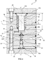
- the hydraulic valve and the control member are arranged in the same body in two parts, namely an anterior part 30 and a rear part 30 ', and are aligned on a longitudinal axis xx'.
- the hydraulic valve comprises a bore 32 of axis xx 'which is made from the anterior face 30a of the anterior part 30 of the body, and which terminates in a frustoconical surface 32a open towards this anterior face 30a and forming a seat of valve against which a ball 36 forming a valve is applied by a compression spring 38.
- the inlet of the bore 32 is closed by a cover 39.
- the front portion 30 of the body is pierced with a conduit 40 of arrival of a hydraulic fluid under pressure which it is desired to control the passage and which opens into the bore 32.
- the latter is extended downstream of the valve seat 32a by a conduit 42 which opens into a chamber 44 which is in communication with an outlet conduit 46 of the fluid under pressure.
- control of this valve that is to say the control of its opening and closing, will be provided by the control member.
- the latter is made from the posterior face 30b of the rear portion 30 'of the body and comprises a cylindrical housing 48 closed at its posterior end by a cover 45 and terminates at its front end by a frustoconical surface 48a against which comes supporting the frustoconical surface 17a of a sealing ring 50 which is traversed by a piston 52.
- the latter is provided with an anterior extension 52 'of smaller diameter which is slidably mounted in a bore 54 which opens into the chamber 44 and which then extends to the valve seat 32a through the conduit 42 so as to be placed in communication with the bore 32.
- a conduit 57 connects the chamber 48 with the outside.
- a spring-compressed triangle seal seals between the body 30 'and the valve extension 52'.
- the piston 52 extends from its anterior end 52a to the vicinity of the ball 36 and has at its rear end a piston head 55 provided with a boss 52b.
- the stroke of this piston 52 is such that it allows it to push the ball 36 as explained below.
- a conduit 53 brings into the housing 48 the control fluid of the control member 1.
- a compression spring 56 is disposed between the rear face 17b of the ring 50 and the piston head 55. As described above, the spring 56 provides both a pre-compression function of the ring 50 and a function of removing the piston 52 when the pilot pressure is removed.
- the conduit 53 is admitted via the conduit into the housing 48, so that it displaces the piston 52 against the action of the spring 38 so that it pushes the ball 36 and opens the valve thus allowing the hydraulic fluid, via the chamber 44, out of the hydraulic valve 29 through the conduit 46.
- the present embodiment of the control member according to the invention is interesting in that it allows, with a low flow and low pressure piloting fluid, to control the passage in a valve of a hydraulic fluid. high flow and high pressure.
- a third example of implementation of the control member according to the invention which is applied to the control of a pressure regulator assembly 59 can also be used as a pressure limiter.
- the pressure regulator assembly 59 comprises a two-part body, namely an anterior portion 60 and a posterior portion 60 '.
- This body comprises a hydraulic fluid inlet duct 62 of longitudinal axis xx 'which is made from the front face 60a of the lower part of the body 60, and which opens into a chamber 64 whose bottom forms a frustoconical surface 66 open towards its rear part and which forms a valve seat.
- the chamber 64 communicates with the outside through an outlet duct 67 of the hydraulic fluid.
- the hydraulic fluid whose pressure is to be regulated arrives in the regulator 59 via the conduit 62 and leaves it via the conduit 67.
- the regulation of the pressure is carried out by a control member 1 according to the invention.
- the latter is made from the rear face 60b of the body 60 'and comprises a cylindrical housing 68 closed by a cover 65 which terminates in a frustoconical surface 69 against which abuts the frustoconical surface 17a of a sealing ring 70 which is traversed by the body of a piston 72.
- the latter comprises a front portion 72 'of smaller diameter which is slidably mounted in a bore 74 which opens into the chamber 64.
- the front portion 72 'of the piston 72 terminates in a hemispherical portion 72a and its rear end terminates in a piston head 75 provided with a boss 72b.
- the stroke of this piston 72 is such that it allows it to come into contact with the valve seat 66 so as to ensure, in this position, the closure of the conduit 62.
- a conduit 71 connects the inlet duct of the fluid 62 hydraulic housing 68 and a conduit 77 connects this housing to the open air.
- a compression spring 76 is disposed between the rear face 17b of the ring 70 and the piston head 75. This spring is compressed so as, on the one hand, to exert on the ring 70 a pre-compression force in the measure of, for example, deforming it so that its cylindrical internal surface comes into contact with the external surface of the piston 72 and, secondly, at a level of compression such as to adjust the value of the level of the pressure P regulated by the pressure regulator assembly 59 .
- the conduit 62 When a pressurized hydraulic fluid is admitted through the conduit 62, the conduit 62 enters the housing 68, via the conduit 71, and exerts on the piston head 75 a force directed towards the front part of the assembly, at the against the compressive force F R of the spring 76.
- the pressure P A of the hydraulic fluid admitted via the conduit 62 remains lower than a value generating on the piston a force F A less than the compression force F R of the spring 76, the hemispherical end 72a thereof remains remote from the valve seat 66 and the pressurized fluid flows freely from its intake duct 62 to its outlet duct 67.
- the compression spring 76 provides three functions, namely: firstly it creates a preload of the sealing ring 70, secondly it adjusts the value of the pressure of the fluid to control and, thirdly, it returns the piston to its open position of the valve.
- the sealing ring is preferably made of a relatively rigid plastic material, such as in particular polytetrafluoroethylene, polyurethane, a polymer thermoplastic or a fluorinated polymer loaded or not with one or more additives able to reduce its coefficient of friction.
- a relatively rigid plastic material such as in particular polytetrafluoroethylene, polyurethane, a polymer thermoplastic or a fluorinated polymer loaded or not with one or more additives able to reduce its coefficient of friction.
- this sealing ring 7 The rigid nature of the material used to form this sealing ring 7 means that the latter is not subject to the phenomenon of extrusion between the piston and the bore when the pressurized fluid is admitted, which considerably simplifies the constitution of the sealing assembly by eliminating the need for the establishment of an anti-extrusion ring.
Abstract
La présente invention concerne un organe de pilotage (1) comprenant un corps (3) percé d'un alésage axial (5) dans lequel est monté mobile en translation un piston (11) dont l'extrémité antérieure (11a) est apte à sortir du corps (3). Cet organe de pilotage est caractérisé en ce que :- l'alésage (5) débouche dans un logement (7) de plus grand diamètre, qui comporte au niveau de l'intersection de celui-ci avec l'alésage (5) une surface tronconique (15) ouverte vers sa partie postérieure et inclinée par rapport à l'axe longitudinal (xx') de l'alésage (5) d'un angle (α) compris entre 30° et 65°,- une bague d'étanchéité (17) pourvue d'une face antérieure tronconique est enfilée sur le piston (11) de façon telle que cette face tronconique soit en appui sur la surface tronconique (15) du logement (7),- le piston (11) possède à son extrémité postérieure une tête (13),- un ressort de compression (19) est disposé entre cette tête (13) et la face postérieure de la bague d'étanchéité (17).The present invention relates to a control member (1) comprising a body (3) pierced with an axial bore (5) in which is mounted movably in translation a piston (11) whose front end (11a) is able to exit of the body (3). This control member is characterized in that: - the bore (5) opens into a housing (7) of larger diameter, which comprises at the intersection thereof with the bore (5) a surface frustoconical section (15) open towards its posterior part and inclined relative to the longitudinal axis (xx ') of the bore (5) by an angle (α) of between 30 ° and 65 °, - a sealing ring (17) provided with a frustoconical anterior face is threaded on the piston (11) so that the frustoconical face bears on the frustoconical surface (15) of the housing (7), - the piston (11) has on its posterior end a head (13), - a compression spring (19) is disposed between this head (13) and the rear face of the sealing ring (17).
Description
La présente invention concerne un organe de pilotage notamment destiné à contrôler l'ouverture et la fermeture de circuits hydrauliques et notamment par exemple des valves de séquences sensibles à la pression. Elle concerne plus particulièrement les organes de pilotage de faibles débits et grande sensibilité et qui, de plus, sont de faibles dimensions.The present invention relates to a control member in particular for controlling the opening and closing of hydraulic circuits and in particular for example valves of pressure-sensitive sequences. It relates more particularly to low speed and high sensitivity control members and which, moreover, are of small dimensions.
La présente invention concerne également les poussoirs hydrauliques c'est à dire des dispositifs destinés à exercer une force de bridage d'éléments sur des outillages automatisés par exemple. Elle concerne préférentiellement des poussoirs hydrauliques de petites dimensions.The present invention also relates to hydraulic pushers, that is to say devices intended to exert a clamping force of elements on automated tools for example. It preferably relates to small hydraulic pushers.
On sait par ailleurs que les organes de commande qui sont destinés à gérer le fonctionnement des circuits hydrauliques et notamment des circuits hydrauliques de puissance aptes à fournir de forts débits de fluide hydraulique, doivent néanmoins être d'une grande sensibilité et être en mesure de fonctionner sous des débits hydrauliques extrêmement faibles.It is also known that the control members which are intended to manage the operation of hydraulic circuits and in particular hydraulic power circuits able to provide high hydraulic fluid flow rates, must nevertheless be of great sensitivity and be able to operate under extremely low hydraulic flows.
Il en résulte que de tels circuits font appel à des éléments actionneurs qui sont constitués de pistons de faible diamètre qui doivent être déplacés dans des conditions de faible frottement à l'intérieur d'un alésage.As a result, such circuits use actuator elements which consist of small diameter pistons which must be moved under low friction conditions within a bore.
La présente invention a pour but de proposer un tel organe de pilotage qui est apte à constituer un poussoir hydraulique ainsi qu'un organe de pilotage notamment pour des vannes hydrauliques et des régulateurs ou des limiteurs de pression.The present invention aims to provide such a steering member which is adapted to constitute a hydraulic pusher and a control member especially for hydraulic valves and regulators or pressure limiters.
Elle a ainsi pour objet un organe de pilotage comprenant un corps percé d'un alésage axial dans lequel est monté mobile en translation un piston dont l'extrémité antérieure est apte à sortir du corps, caractérisé en ce que :
- l'alésage débouche dans un logement de plus grand diamètre, qui comporte au niveau de l'intersection de celui-ci avec l'alésage une surface tronconique ouverte vers sa partie postérieure et inclinée par rapport à l'axe longitudinal de l'alésage d'un angle compris entre 30° et 65°,
- une bague d'étanchéité pourvue d'une face antérieure tronconique est enfilée sur le piston de façon telle que cette face tronconique soit en appui sur la surface tronconique du logement,
- le piston possède à son extrémité postérieure une tête,
- un ressort de compression est disposé entre cette tête et la face postérieure de la bague d'étanchéité.
- the bore opens into a housing of larger diameter, which comprises at the intersection thereof with the bore a frustoconical surface open towards its posterior part and inclined with respect to the longitudinal axis of the bore by an angle of between 30 ° and 65 °,
- a sealing ring provided with a frustoconical front face is threaded onto the piston so that this frustoconical face bears against the frustoconical surface of the housing,
- the piston has at its rear end a head,
- a compression spring is disposed between this head and the rear face of the sealing ring.
La bague d'étanchéité pourra être préférentiellement constituée d'un polymère thermoplastique ou d'un polymère fluoré chargé ou non d'un ou plusieurs additifs aptes à diminuer son coefficient de frottement et sa dureté sera notamment comprise entre 85 et 97 shore A.The sealing ring may preferably consist of a thermoplastic polymer or a fluorinated polymer with or without one or more additives capable of reducing its coefficient of friction and its hardness will notably be between 85 and 97 shore A.
La présente invention a également pour objet un ensemble de pilotage comportant un organe de pilotage tel que précédemment qui est caractérisé en ce qu'il comporte un logement cylindrique dans lequel est fixé le corps et qui est en communication avec un conduit d'alimentation en fluide de pilotage sous pression, la profondeur de ce logement étant telle que, lorsque la tête de piston est en contact avec le fond du logement, le ressort est dans un état comprimé.The present invention also relates to a steering assembly comprising a control member as previously, which is characterized in that it comprises a cylindrical housing in which the body is fixed and which is in communication with a fluid supply duct. pressure pilot, the depth of this housing being such that, when the piston head is in contact with the bottom of the housing, the spring is in a compressed state.
Préférentiellement le corps sera de forme cylindrique et comportera sur sa périphérie un filetage par lequel il sera vissé dans un filetage interne du logement.Preferably the body will be cylindrical in shape and have on its periphery a thread by which it will be screwed into an internal thread of the housing.
La présente invention a également pour objet un ensemble de pilotage comportant un organe de pilotage tel que défini précédemment caractérisé en ce que :
- le corps est un corps de vanne à partir d'une face antérieure de laquelle est creusé un alésage axial cylindrique se terminant par une surface tronconique orientée vers la face antérieure du corps et formant un siège de clapet, contre lequel est appliqué un élément obturateur sous l'action de moyens élastiques, cet alésage étant alimenté en fluide sous pression par un conduit,
- la sortie du siège de clapet est en communication avec l'extérieur par un conduit de sortie de fluide hydraulique,
- l'organe de pilotage est disposé dans un logement du corps de vanne qui est coaxial à l'alésage et orienté de façon telle que l'extrémité antérieure du piston soit apte à repousser et à relâcher l'élément obturateur lors de son déplacement en translation,
- la profondeur du logement est telle que lorsque la tête de piston est en contact avec le fond de ce logement, le ressort est dans un état comprimé,
- le logement est alimenté en fluide de pilotage sous pression par un conduit.
- the body is a valve body from an anterior face of which is hollowed a cylindrical axial bore ending in a frustoconical surface facing the front face of the body and forming a valve seat, against which is applied an element obturator under the action of elastic means, this bore being fed with pressurized fluid by a conduit,
- the outlet of the valve seat is in communication with the outside by a hydraulic fluid outlet duct,
- the control member is disposed in a housing of the valve body which is coaxial with the bore and oriented so that the anterior end of the piston is able to push back and release the shutter member during its displacement in translation ,
- the depth of the housing is such that when the piston head is in contact with the bottom of this housing, the spring is in a compressed state,
- the housing is supplied with piloting fluid under pressure through a conduit.
Suivant l'invention la sortie du siège de clapet pourra être en communication avec le conduit de sortie par l'intermédiaire d'une chambre.According to the invention the outlet of the valve seat may be in communication with the outlet duct via a chamber.
La présente invention a également pour objet un ensemble de pilotage comportant un organe de pilotage tel que défini précédemment caractérisé en ce que :
- le corps est un corps de régulateur/limiteur de pression à partir d'une face antérieure de laquelle est creusé un alésage axial cylindrique en communication avec des moyens d'alimentation en fluide sous pression se terminant par une surface tronconique ouverte vers la partie postérieure du corps et formant un siège de clapet,
- l'organe de pilotage est disposé dans un logement du corps coaxial à l'alésage et orienté de façon telle que l'extrémité antérieure du piston soit apte à venir obturer et à libérer le siège de clapet lors de son déplacement en translation,
- le logement de l'organe de pilotage est en communication par un conduit avec le conduit d'alimentation en fluide hydraulique sous pression.
- the body is a body of regulator / pressure limiter from an anterior face of which is hollowed a cylindrical axial bore in communication with pressurized fluid supply means terminating in a frustoconical surface open towards the posterior portion of the body and forming a valve seat,
- the control member is disposed in a housing of the body coaxial with the bore and oriented so that the front end of the piston is adapted to close and release the valve seat during its displacement in translation,
- the housing of the control member is in communication with a conduit with the conduit for supplying hydraulic fluid under pressure.
On décrira ci-après, à titre d'exemple non limitatif, des formes d'exécution de la présente invention, en référence au dessin annexé sur lequel :
- la
figure 1 est une vue en coupe axiale et longitudinale d'un organe de pilotage suivant l'invention avant sa mise en place dans un logement récepteur, - la figure la et une vue partielle agrandie d'une partie de l'organe de pilotage représenté sur la
figure 1 , - la
figure 2 est une vue en coupe axiale et longitudinale de l'organe de pilotage représenté sur lesfigures 1 et la après sa mise en place dans un logement récepteur, dans une application de poussoir hydraulique, - les
figures 3a et 3b sont des vues en coupe diamétrale de deux variantes de réalisation d'une bague d'étanchéité mise en oeuvre dans l'organe de pilotage suivant la présente invention, - la
figure 4 est une vue en coupe axiale et longitudinale d'un second mode de mise en oeuvre d'un organe de pilotage suivant l'invention dans une application de pilotage d'une vanne hydraulique, - la
figure 5 est une vue en coupe axiale et longitudinale d'un troisième mode de mise en oeuvre d'un organe de pilotage suivant l'invention dans une application de pilotage d'un ensemble régulateur/limiteur de pression.
- the
figure 1 is a view in axial and longitudinal section of a control member according to the invention before it is placed in a receiver housing, - Figure la and an enlarged partial view of a portion of the steering member shown on the
figure 1 , - the
figure 2 is an axial and longitudinal sectional view of the steering member shown in FIGS.figures 1 and after it is put in place in a receiver housing, in a hydraulic pusher application, - the
Figures 3a and 3b are views in diametral section of two embodiments of a sealing ring implemented in the control member according to the present invention, - the
figure 4 is a view in axial and longitudinal section of a second embodiment of a control member according to the invention in an application for controlling a hydraulic valve, - the
figure 5 is a view in axial and longitudinal section of a third embodiment of a control member according to the invention in a control application of a regulator / pressure limiter assembly.
On a représenté sur la
L'alésage axial 5 reçoit un piston cylindrique 11 d'axe longitudinal xx' qui est monté à coulissement dans celui-ci et qui se termine à sa partie postérieure par une tête de piston 13.The
La partie antérieure du logement 7 se termine par une surface tronconique 15 qui est inclinée par rapport à l'axe xx' de l'organe de pilotage d'un angle aigu α ouvert vers la partie postérieure de ce logement, ainsi que représenté sur les
Une bague d'étanchéité 17 de type dit « triangle » est montée coulissante sur le piston 11.A
Ainsi que représenté sur les
La bague 17 comporte des moyens de précharge qui, en l'absence de fluide sous pression, appliquent la face tronconique 17a de la bague 17 contre la surface tronconique 15 du logement 7.The
Ces moyens de précharge sont constitués en l'espèce d'un ressort de compression 19 qui est enfilé sur le piston 11 et qui est en appui d'une part sur la face postérieure 17b de la bague 17 et sur la tête 13 du piston 11. On comprend que, dans ces conditions la force de précharge exercée par le ressort 19 sur la bague 17 est fonction d'une part de la raideur de celui-ci et d'autre part de son état de compression qui est lui-même fonction de la position longitudinale de la tête de piston 13 par rapport à la surface tronconique 15.These preloading means consist in this case of a
Ainsi que représenté sur la
On déterminera la longueur e de l'alésage borgne 21 de façon que, compte tenu de la raideur du ressort 19 ce dernier se trouve dans un état de compression en mesure d'exercer sur la face postérieure 17b de la bague 17 une force de précharge f correspondant à la précharge que l'on souhaite appliquer à la bague d'étanchéité 17.The length e of the blind bore 21 will be determined so that, given the stiffness of the
La structure support 9 est percée d'un conduit 23 qui débouche dans la partie postérieure de l'alésage 21 et par lequel arrive un fluide hydraulique sous une pression P, dit fluide de pilotage.The
On comprend que, dans ces conditions, lorsque ce dernier n'est pas admis par le conduit 23, le ressort 19, qui est comprimé, applique à la bague d'étanchéité 17 la force de précharge axiale f, si bien que la composante radiale fr de celle-ci applique la surface 17c de la bague sur la surface externe du piston 11.It is understood that, under these conditions, when the latter is not admitted through
Lorsque le fluide de pilotage P est admis par le conduit 23 dans l'alésage 21, il repousse alors le piston 11 vers la partie antérieure de l'organe de pilotage en comprimant le ressort 19 qui, dès lors, exerce sur la bague d'étanchéité 17 une force axiale supplémentaire F dont la composante radiale Fr applique alors la surface 17c de la bague sur la surface externe du piston, assurant ainsi l'étanchéité entre ce dernier et le corps cylindrique 3.When the piloting fluid P is admitted via the
Ensuite, lorsque l'on stoppe l'arrivée du fluide de pilotage, le ressort 19 ramène alors le piston 11 à sa position primitive en état de précharge de la bague d'étanchéité 17.Then, when the arrival of the piloting fluid is stopped, the
La présente invention est intéressante en ce que, dans un tel mode de mise en oeuvre, le ressort 19 assure deux fonctions, à savoir, d'une part, la précharge de la bague d'étanchéité 17 et, d'autre part, le retour du piston 21 lorsque l'on stoppe l'arrivée du fluide de pilotage.The present invention is interesting in that, in such an embodiment, the
On comprend qu'un tel mode de mise en oeuvre peut être avantageusement utilisé dans toutes les applications du type précédemment décrit, mais également dans des applications de vérin simple effet à gorge ouverte, et notamment dans celles où il est nécessaire de disposer d'un organe de pilotage sous une forme miniaturisée.It is understood that such an implementation mode can be advantageously used in all applications of the type previously described, but also in single-jack open-throat jack applications, particularly in those where it is necessary to have a steering organ in a miniaturized form.
En effet la bague d'étanchéité 17 qui est utilisée sur cet organe de pilotage 1 permet une miniaturisation de celui-ci, dans la mesure où, en raison de sa forme en triangle et de sa nature, notamment un matériau de type polytétrafluoréthylène, elle est en mesure d'être suffisamment rigide pour être sollicitée directement par un ressort de compression et néanmoins suffisamment plastique pour se déformer et, en raison de sa forme, se serrer sur le piston pour assurer l'étanchéité au fluide hydraulique sous pression.Indeed, the sealing
Dans la mesure où l'organe de pilotage suivant l'invention est un dispositif dit «en gorge ouverte» puisque le logement cylindrique 7 recevant le piston 11 et la bague d'étanchéité 17 est ouvert sur l'extérieur, il permet de recevoir des bagues d'étanchéité dont la plasticité est plus faible que celle du polytétrafluoréthylène. Dans une telle forme de mise en oeuvre on interposera entre le ressort de compression et la bague d'étanchéité une rondelle rigide qui répartira sur la surface de la bague la force exercée par le ressort. La bague pourra ainsi être constituée de polyacétal, de plastiques techniques chargés notamment par du talc, du bisulfure de molybdène, de la fibre de verre ou de la poudre de bronze.Insofar as the drive member according to the invention is a so-called "open groove" device since the
On a représenté sous forme schématique sur la
Dans ce mode de mise en oeuvre la vanne hydraulique et l'organe de pilotage sont disposés dans un même corps en deux parties, à savoir une partie antérieure 30 et une partie postérieure 30', et sont alignés sur un axe longitudinal xx' . La vanne hydraulique comprend un alésage 32 d'axe xx' qui est réalisé à partir de la face antérieure 30a de la partie antérieure 30 du corps, et qui se termine par une surface tronconique 32a ouverte vers cette face antérieure 30a et formant un siège de clapet contre lequel une bille 36 formant clapet est appliquée par un ressort de compression 38. L'entrée de l'alésage 32 est fermée par un couvercle 39. La partie antérieure 30 du corps est percée d'un conduit 40 d'arrivée d'un fluide hydraulique sous pression dont on souhaite contrôler le passage et qui débouche dans l'alésage 32.In this embodiment, the hydraulic valve and the control member are arranged in the same body in two parts, namely an
Ce dernier se prolonge en aval du siège de clapet 32a par un conduit 42 qui débouche dans une chambre 44 qui est en communication avec un conduit de sortie 46 du fluide sous pression.The latter is extended downstream of the
En l'état, lorsque le liquide sous pression est admis par le conduit 40 dans l'alésage 32 il repousse conjointement au ressort 38 la bille 36 et applique cette dernière contre le siège de clapet 32a bloquant ainsi la sortie du fluide sous pression.In the state, when the pressurized liquid is admitted through the
Suivant l'invention le pilotage de cette vanne, c'est-à-dire le contrôle de son ouverture et de sa fermeture, sera assuré par l'organe de pilotage.According to the invention the control of this valve, that is to say the control of its opening and closing, will be provided by the control member.
Ce dernier est réalisé à partir de la face postérieure 30b de la partie 30' postérieure du corps et comprend un logement cylindrique 48 fermé à son extrémité postérieure par un couvercle 45 et se termine à son extrémité antérieure par une surface tronconique 48a contre laquelle vient en appui la surface tronconique 17a d'une bague d'étanchéité 50 qui est traversée par un piston 52. Ce dernier est pourvu d'une prolongation antérieure 52' de plus petit diamètre qui est montée à coulissement dans un alésage 54 qui débouche dans la chambre 44 et qui se prolonge ensuite jusqu'au siège de clapet 32a par le conduit 42 de façon à pouvoir être mis en communication avec l'alésage 32. Un conduit 57 relie la chambre 48 avec l'extérieur. Un joint triangle comprimé par un ressort assure l'étanchéité entre le corps 30' et la prolongation de clapet 52'.The latter is made from the
Le piston 52 s'étend par son extrémité antérieure 52a jusqu'au voisinage de la bille 36 et possède à son extrémité postérieure une tête de piston 55 pourvue d'un bossage 52b. La course de ce piston 52 est telle qu'elle lui permet de repousser la bille 36 ainsi qu'expliqué ci-après. Un conduit 53 amène dans le logement 48 le fluide de pilotage de l'organe de pilotage 1.The
Un ressort de compression 56 est disposé entre la face postérieure 17b de la bague 50 et la tête de piston 55. Ainsi que décrit précédemment le ressort 56 assure à la fois une fonction de pré-compression de la bague 50 et une fonction de retrait du piston 52 lorsque la pression de pilotage est supprimée.A
Lorsque l'on souhaite ouvrir la vanne hydraulique, on admet par le conduit 53 le fluide de pilotage dans le logement 48, si bien que celui-ci déplace le piston 52 à l'encontre de l'action du ressort 38 de façon qu'il repousse la bille 36 et ouvre la vanne permettant ainsi au fluide hydraulique, via la chambre 44, de sortir de la vanne hydraulique 29 par le conduit 46.When it is desired to open the hydraulic valve, the
Lorsque l'on souhaite fermer cette dernière, on interrompt l'alimentation de l'organe de pilotage en fluide de pilotage et le ressort de compression 56 ramène alors le piston 52 dans sa position initiale et le fluide hydraulique alimentant la vanne 29 applique alors la bille 36 contre le siège de clapet 32a assurant ainsi la fermeture de ladite vanne.When it is desired to close the latter, it interrupts the supply of the piloting fluid control fluid and the
Le présent mode de mise en oeuvre de l'organe de pilotage suivant l'invention est intéressant en ce qu'il permet, avec un fluide de pilotage de faible débit et faible pression, de commander le passage dans une vanne d'un fluide hydraulique de grand débit et forte pression.The present embodiment of the control member according to the invention is interesting in that it allows, with a low flow and low pressure piloting fluid, to control the passage in a valve of a hydraulic fluid. high flow and high pressure.
On a représenté sous forme schématique sur la
L'ensemble régulateur de pression 59 comprend un corps en deux parties, à savoir une partie antérieure 60 et une partie postérieure 60'. Ce corps comprend un conduit d'arrivée de fluide hydraulique 62 d'axe longitudinal xx' qui est réalisé à partir de la face antérieure 60a de la partie inférieure du corps 60, et qui débouche dans une chambre 64 dont le fond forme une surface tronconique 66 ouverte vers sa partie postérieure et qui forme un siège de clapet. La chambre 64 communique avec l'extérieur par un conduit de sortie 67 du fluide hydraulique. Ainsi le fluide hydraulique dont on souhaite réguler la pression arrive dans le régulateur 59 par le conduit 62 et en ressort par le conduit 67.The
Suivant l'invention la régulation de la pression est effectuée par un organe de pilotage 1 suivant l'invention.According to the invention the regulation of the pressure is carried out by a
Ce dernier est réalisé à partir de la face postérieure 60b du corps 60' et comprend un logement cylindrique 68 fermé par un couvercle 65 qui se termine par une surface tronconique 69 contre laquelle vient en appui la surface tronconique 17a d'une bague d'étanchéité 70 qui est traversée par le corps d'un piston 72. Ce dernier comporte une partie antérieure 72' de plus petit diamètre qui est montée à coulissement dans un alésage 74 qui débouche dans la chambre 64. Un joint d'étanchéité 73 de type triangle comprimé par un ressort assure l'étanchéité entre le corps 60 et la partie antérieure 72' du piston 72. Cette dernière se prolonge jusqu'au voisinage du siège de clapet 66 de façon à pouvoir être mise en contact avec celui-ci lors de son déplacement longitudinal.The latter is made from the
La partie antérieure 72' du piston 72 se termine par une partie hémisphérique 72a et son extrémité postérieure se termine par une tête de piston 75 pourvue d'un bossage 72b. La course de ce piston 72 est telle qu'elle lui permet de venir en contact avec le siège de clapet 66 de façon à assurer, dans cette position, l'obturation du conduit 62. Un conduit 71 relie le conduit d'admission du fluide hydraulique 62 au logement 68 et un conduit 77 relie ce logement à l'air libre.The front portion 72 'of the
Un ressort de compression 76 est disposé entre la face postérieure 17b de la bague 70 et la tête de piston 75. Ce ressort est comprimé de façon d'une part à exercer sur la bague 70 un effort de précompression en mesure, par exemple, de le déformer de façon que sa surface interne cylindrique vienne en contact avec la surface externe du piston 72 et, de seconde part à un niveau de compression tel permettant de régler la valeur du niveau de la pression P régulé par l'ensemble régulateur de pression 59.A
Lorsqu'un fluide hydraulique sous pression est admis par le conduit 62, celui-ci pénètre dans le logement 68, via le conduit 71, et exerce sur la tête de piston 75 une force dirigée vers la partie antérieure de l'ensemble, à l'encontre de la force de compression F R du ressort 76. Tant que la pression P A du fluide hydraulique admis par le conduit 62 reste inférieure à une valeur générant sur le piston une force F A inférieure à la force de compression F R du ressort 76, l'extrémité hémisphérique 72a de celui-ci reste éloignée du siège de clapet 66 et le fluide sous pression circule librement de son conduit d'admission 62 vers son conduit de sortie 67.When a pressurized hydraulic fluid is admitted through the
Lorsque la pression du fluide hydraulique vient à atteindre une valeur P A' telle que la force F A' qu'il exerce sur le piston 72 dépasse la force F R générée par le ressort 76, alors le piston 72 se déplace et son extrémité hémisphérique 72a vient au contact du siège de clapet 66 obturant ainsi l'arrivée du fluide sous pression.When the pressure of the hydraulic fluid reaches a value P A ' such that the force F A' that it exerts on the
A l'inverse, dès que la pression P A du fluide hydraulique diminue et que la force F A qu'il exerce sur le piston devient inférieure à la force de compression F R du ressort, ce dernier ramène le piston à sa positon initiale, si bien que ce dernier libère le siège de clapet 66 permettant alors la libre circulation du fluide sous pression.Conversely, as soon as the pressure P A of the hydraulic fluid decreases and the force F A that it exerts on the piston becomes lower than the compression force F R of the spring, the latter returns the piston to its initial position, so that it releases the
On notera que dans le présent mode de mise en oeuvre le ressort de compression 76 assure trois fonctions, à savoir : de première part il crée une précharge de la bague d'étanchéité 70, de seconde part il règle la valeur de la pression du fluide à contrôler et, de troisième part, il ramène le piston à sa position d'ouverture de la vanne.Note that in the present embodiment of the
Suivant l'invention, la bague d'étanchéité, est préférentiellement constituée d'un matériau plastique relativement rigide, tel que notamment du polytétrafluoréthylène, du polyuréthane, un polymère thermoplastique ou un polymère fluoré chargé ou non d'un ou plusieurs additifs aptes à diminuer son coefficient de frottement.According to the invention, the sealing ring is preferably made of a relatively rigid plastic material, such as in particular polytetrafluoroethylene, polyurethane, a polymer thermoplastic or a fluorinated polymer loaded or not with one or more additives able to reduce its coefficient of friction.
La nature rigide du matériau utilisé pour constituer cette bague d'étanchéité 7 fait que cette dernière n'est pas sujette au phénomène d'extrusion entre le piston et l'alésage lorsque le fluide sous pression est admis, ce qui simplifie notablement la constitution de l'ensemble d'étanchéité en supprimant la nécessité de la mise en place d'une bague anti-extrusion.The rigid nature of the material used to form this
On notera par ailleurs qu'en faisant varier la valeur de l'angle α on fait varier du même coup la valeur de la composante radiale Fr de la force exercée par le fluide sous pression sur le piston. On permet ainsi au concepteur de contrôler cette force d'application et ceci, notamment en fonction d'une part des applications à réaliser et, d'autre part, de la valeur de la pression P du fluide de pilotage. Ainsi, si l'on souhaite réaliser un organe de pilotage qui soit sensible à la pression du fluide sous pression, autrement dit dans lequel la pression exercée sur le piston augmente plus rapidement avec la pression du fluide, on diminuera la valeur de l'angle α et, à l'inverse, on augmentera celui-ci.Note also that by varying the value of the angle α is simultaneously changing the value of the radial component Fr of the force exerted by the fluid under pressure on the piston. This allows the designer to control this application force and this, in particular as a function, on the one hand, of the applications to be performed and, on the other hand, of the value of the pressure P of the piloting fluid. Thus, if it is desired to provide a control member which is sensitive to the pressure of the fluid under pressure, in other words in which the pressure exerted on the piston increases more rapidly with the pressure of the fluid, the value of the angle will be decreased. α and, conversely, we will increase it.
Claims (9)
Priority Applications (1)
| Application Number | Priority Date | Filing Date | Title |
|---|---|---|---|
| PL19156682T PL3524860T3 (en) | 2018-02-13 | 2019-02-12 | Control member |
Applications Claiming Priority (1)
| Application Number | Priority Date | Filing Date | Title |
|---|---|---|---|
| FR1870154A FR3077859B1 (en) | 2018-02-13 | 2018-02-13 | AXIAL PRELOAD SEALING ASSEMBLY |
Publications (2)
| Publication Number | Publication Date |
|---|---|
| EP3524860A1 true EP3524860A1 (en) | 2019-08-14 |
| EP3524860B1 EP3524860B1 (en) | 2021-04-07 |
Family
ID=61764040
Family Applications (1)
| Application Number | Title | Priority Date | Filing Date |
|---|---|---|---|
| EP19156682.7A Active EP3524860B1 (en) | 2018-02-13 | 2019-02-12 | Control member |
Country Status (5)
| Country | Link |
|---|---|
| EP (1) | EP3524860B1 (en) |
| ES (1) | ES2882059T3 (en) |
| FR (1) | FR3077859B1 (en) |
| HU (1) | HUE054959T2 (en) |
| PL (1) | PL3524860T3 (en) |
Citations (3)
| Publication number | Priority date | Publication date | Assignee | Title |
|---|---|---|---|---|
| US1597254A (en) * | 1924-08-06 | 1926-08-24 | Joseph A Vogel | Stuffing box for water-closet or hydrant valves, pumps, etc. |
| US3029061A (en) * | 1959-07-16 | 1962-04-10 | Don R Hoxworth | Air-hydraulic control unit |
| DE202008005469U1 (en) * | 2008-04-18 | 2008-07-03 | Bürkert Werke GmbH & Co.KG | Valve with pneumatic drive unit |
Family Cites Families (7)
| Publication number | Priority date | Publication date | Assignee | Title |
|---|---|---|---|---|
| US1827903A (en) * | 1930-01-15 | 1931-10-20 | George V Panyard | Piston packing |
| GB638164A (en) * | 1947-04-25 | 1950-05-31 | Jean Alfred Troendle | Improvements relating to fluid-tight packing means |
| US3269737A (en) * | 1963-11-12 | 1966-08-30 | Cessna Aircraft Co | Unbalanced pressure shaft seal |
| DE2629142A1 (en) * | 1976-06-29 | 1978-01-12 | United Stirling Ab & Co | Wedge section oil scraper ring - of glass reinforced PTFE, for piston rod of double acting engine |
| GB2115518A (en) * | 1982-02-16 | 1983-09-07 | John Harbidge | Sealing means |
| FR2590641B1 (en) * | 1985-11-25 | 1989-07-13 | Snecma | COMPOSITE SEALING DEVICE |
| US10107401B2 (en) * | 2014-09-24 | 2018-10-23 | Nok Corporation | Sealing structure |
-
2018
- 2018-02-13 FR FR1870154A patent/FR3077859B1/en active Active
-
2019
- 2019-02-12 PL PL19156682T patent/PL3524860T3/en unknown
- 2019-02-12 EP EP19156682.7A patent/EP3524860B1/en active Active
- 2019-02-12 HU HUE19156682A patent/HUE054959T2/en unknown
- 2019-02-12 ES ES19156682T patent/ES2882059T3/en active Active
Patent Citations (3)
| Publication number | Priority date | Publication date | Assignee | Title |
|---|---|---|---|---|
| US1597254A (en) * | 1924-08-06 | 1926-08-24 | Joseph A Vogel | Stuffing box for water-closet or hydrant valves, pumps, etc. |
| US3029061A (en) * | 1959-07-16 | 1962-04-10 | Don R Hoxworth | Air-hydraulic control unit |
| DE202008005469U1 (en) * | 2008-04-18 | 2008-07-03 | Bürkert Werke GmbH & Co.KG | Valve with pneumatic drive unit |
Also Published As
| Publication number | Publication date |
|---|---|
| PL3524860T4 (en) | 2021-11-02 |
| PL3524860T3 (en) | 2021-11-02 |
| FR3077859B1 (en) | 2020-06-19 |
| FR3077859A1 (en) | 2019-08-16 |
| EP3524860B1 (en) | 2021-04-07 |
| ES2882059T3 (en) | 2021-12-01 |
| HUE054959T2 (en) | 2021-10-28 |
Similar Documents
| Publication | Publication Date | Title |
|---|---|---|
| EP1106212B1 (en) | Nozzle for fire-fighting | |
| CA2774320C (en) | Fuel flowmeter having an improved control device | |
| FR2469988A1 (en) | PROJECTION ADJUSTMENT OF A HIGH PRESSURE CUTTING JET | |
| FR2834016A1 (en) | Jet pump for transferring fuel between different compartments in multi-compartment fuel tanks, has sealing elements each adapted to open when pressure of injected fluid exceeds predetermined level | |
| EP2006587A1 (en) | Watertight valve system | |
| FR2941762A1 (en) | DEVICE FOR SELECTIVELY SEALING A FLUID PASSAGE, AND TAP COMPRISING SUCH A DEVICE | |
| EP3002499B1 (en) | Valve closure device by actuating the expansion valve | |
| EP0342091B1 (en) | Controlled valve for an antilock system | |
| FR2551525A1 (en) | AXIAL FLOW PRESSURE REGULATOR | |
| FR2790812A1 (en) | DIRECTIONAL VALVE WITH TRIP THRESHOLD AND DEVICE PROVIDED WITH SUCH A VALVE | |
| EP3524860B1 (en) | Control member | |
| EP3308235B1 (en) | Compact and pressure-balanced fluid regulator | |
| FR2543504A1 (en) | PRESSURE LIMIT VALVE FOR COMPRESSED AIR BRAKING SYSTEMS ON MOTOR VEHICLES | |
| FR2955170A1 (en) | Gas expander integrated tap for use in pressurized gas cylinder, has push-valve and pressure valve arranged in same housing of body, where push-valve is selectively moved independent of pressure valve for actuating insulation valve | |
| EP0378947B1 (en) | Vent valve | |
| FR2563312A1 (en) | PRESSURE REDUCTION VALVE | |
| EP3477415B1 (en) | Thermostatic valve | |
| FR2746154A1 (en) | HYDROPNEUMATIC CONTROL BRAKE | |
| FR3000773A1 (en) | Hydraulic control device for controlling clutch of car, has elastic element placed between portable unit and end of piston, and locking unit for alternatively locking portable unit with body or piston | |
| FR2834017A1 (en) | Jet pump comprises body housing jet and suction orifice, auxiliary chamber upstream of jet outlet associated with sealed element able to break when pre-specified pressure is exceeded by injected fluid | |
| FR2724212A1 (en) | IMPROVED REGULATOR FOR A PRESSURIZED FLUID | |
| FR3018931A1 (en) | COMPENSATION AND COMPACT REGULATOR FOR PRESSURE FLUID DISTRIBUTION | |
| FR2805004A1 (en) | Throttle, esp for fuel injector, comprises insert set in bore cavity with lining sleeve of softer material | |
| FR3069610A1 (en) | THERMOSTATIC VALVE | |
| WO1990002899A1 (en) | High pressure valve usable particularly in a fluid jet cutting tool |
Legal Events
| Date | Code | Title | Description |
|---|---|---|---|
| PUAI | Public reference made under article 153(3) epc to a published international application that has entered the european phase |
Free format text: ORIGINAL CODE: 0009012 |
|
| STAA | Information on the status of an ep patent application or granted ep patent |
Free format text: STATUS: THE APPLICATION HAS BEEN PUBLISHED |
|
| AK | Designated contracting states |
Kind code of ref document: A1 Designated state(s): AL AT BE BG CH CY CZ DE DK EE ES FI FR GB GR HR HU IE IS IT LI LT LU LV MC MK MT NL NO PL PT RO RS SE SI SK SM TR |
|
| AX | Request for extension of the european patent |
Extension state: BA ME |
|
| STAA | Information on the status of an ep patent application or granted ep patent |
Free format text: STATUS: REQUEST FOR EXAMINATION WAS MADE |
|
| 17P | Request for examination filed |
Effective date: 20200213 |
|
| RBV | Designated contracting states (corrected) |
Designated state(s): AL AT BE BG CH CY CZ DE DK EE ES FI FR GB GR HR HU IE IS IT LI LT LU LV MC MK MT NL NO PL PT RO RS SE SI SK SM TR |
|
| GRAP | Despatch of communication of intention to grant a patent |
Free format text: ORIGINAL CODE: EPIDOSNIGR1 |
|
| STAA | Information on the status of an ep patent application or granted ep patent |
Free format text: STATUS: GRANT OF PATENT IS INTENDED |
|
| INTG | Intention to grant announced |
Effective date: 20201207 |
|
| GRAS | Grant fee paid |
Free format text: ORIGINAL CODE: EPIDOSNIGR3 |
|
| GRAA | (expected) grant |
Free format text: ORIGINAL CODE: 0009210 |
|
| STAA | Information on the status of an ep patent application or granted ep patent |
Free format text: STATUS: THE PATENT HAS BEEN GRANTED |
|
| AK | Designated contracting states |
Kind code of ref document: B1 Designated state(s): AL AT BE BG CH CY CZ DE DK EE ES FI FR GB GR HR HU IE IS IT LI LT LU LV MC MK MT NL NO PL PT RO RS SE SI SK SM TR |
|
| REG | Reference to a national code |
Ref country code: GB Ref legal event code: FG4D Free format text: NOT ENGLISH |
|
| REG | Reference to a national code |
Ref country code: AT Ref legal event code: REF Ref document number: 1380100 Country of ref document: AT Kind code of ref document: T Effective date: 20210415 Ref country code: CH Ref legal event code: EP |
|
| REG | Reference to a national code |
Ref country code: DE Ref legal event code: R096 Ref document number: 602019003650 Country of ref document: DE |
|
| REG | Reference to a national code |
Ref country code: IE Ref legal event code: FG4D Free format text: LANGUAGE OF EP DOCUMENT: FRENCH |
|
| REG | Reference to a national code |
Ref country code: LT Ref legal event code: MG9D |
|
| REG | Reference to a national code |
Ref country code: NL Ref legal event code: MP Effective date: 20210407 Ref country code: AT Ref legal event code: MK05 Ref document number: 1380100 Country of ref document: AT Kind code of ref document: T Effective date: 20210407 |
|
| REG | Reference to a national code |
Ref country code: HU Ref legal event code: AG4A Ref document number: E054959 Country of ref document: HU |
|
| PG25 | Lapsed in a contracting state [announced via postgrant information from national office to epo] |
Ref country code: FI Free format text: LAPSE BECAUSE OF FAILURE TO SUBMIT A TRANSLATION OF THE DESCRIPTION OR TO PAY THE FEE WITHIN THE PRESCRIBED TIME-LIMIT Effective date: 20210407 Ref country code: HR Free format text: LAPSE BECAUSE OF FAILURE TO SUBMIT A TRANSLATION OF THE DESCRIPTION OR TO PAY THE FEE WITHIN THE PRESCRIBED TIME-LIMIT Effective date: 20210407 Ref country code: LT Free format text: LAPSE BECAUSE OF FAILURE TO SUBMIT A TRANSLATION OF THE DESCRIPTION OR TO PAY THE FEE WITHIN THE PRESCRIBED TIME-LIMIT Effective date: 20210407 Ref country code: NL Free format text: LAPSE BECAUSE OF FAILURE TO SUBMIT A TRANSLATION OF THE DESCRIPTION OR TO PAY THE FEE WITHIN THE PRESCRIBED TIME-LIMIT Effective date: 20210407 Ref country code: BG Free format text: LAPSE BECAUSE OF FAILURE TO SUBMIT A TRANSLATION OF THE DESCRIPTION OR TO PAY THE FEE WITHIN THE PRESCRIBED TIME-LIMIT Effective date: 20210707 Ref country code: AT Free format text: LAPSE BECAUSE OF FAILURE TO SUBMIT A TRANSLATION OF THE DESCRIPTION OR TO PAY THE FEE WITHIN THE PRESCRIBED TIME-LIMIT Effective date: 20210407 |
|
| PG25 | Lapsed in a contracting state [announced via postgrant information from national office to epo] |
Ref country code: PT Free format text: LAPSE BECAUSE OF FAILURE TO SUBMIT A TRANSLATION OF THE DESCRIPTION OR TO PAY THE FEE WITHIN THE PRESCRIBED TIME-LIMIT Effective date: 20210809 Ref country code: SE Free format text: LAPSE BECAUSE OF FAILURE TO SUBMIT A TRANSLATION OF THE DESCRIPTION OR TO PAY THE FEE WITHIN THE PRESCRIBED TIME-LIMIT Effective date: 20210407 Ref country code: RS Free format text: LAPSE BECAUSE OF FAILURE TO SUBMIT A TRANSLATION OF THE DESCRIPTION OR TO PAY THE FEE WITHIN THE PRESCRIBED TIME-LIMIT Effective date: 20210407 Ref country code: LV Free format text: LAPSE BECAUSE OF FAILURE TO SUBMIT A TRANSLATION OF THE DESCRIPTION OR TO PAY THE FEE WITHIN THE PRESCRIBED TIME-LIMIT Effective date: 20210407 Ref country code: NO Free format text: LAPSE BECAUSE OF FAILURE TO SUBMIT A TRANSLATION OF THE DESCRIPTION OR TO PAY THE FEE WITHIN THE PRESCRIBED TIME-LIMIT Effective date: 20210707 Ref country code: GR Free format text: LAPSE BECAUSE OF FAILURE TO SUBMIT A TRANSLATION OF THE DESCRIPTION OR TO PAY THE FEE WITHIN THE PRESCRIBED TIME-LIMIT Effective date: 20210708 Ref country code: IS Free format text: LAPSE BECAUSE OF FAILURE TO SUBMIT A TRANSLATION OF THE DESCRIPTION OR TO PAY THE FEE WITHIN THE PRESCRIBED TIME-LIMIT Effective date: 20210807 |
|
| REG | Reference to a national code |
Ref country code: ES Ref legal event code: FG2A Ref document number: 2882059 Country of ref document: ES Kind code of ref document: T3 Effective date: 20211201 |
|
| REG | Reference to a national code |
Ref country code: DE Ref legal event code: R097 Ref document number: 602019003650 Country of ref document: DE |
|
| PG25 | Lapsed in a contracting state [announced via postgrant information from national office to epo] |
Ref country code: SM Free format text: LAPSE BECAUSE OF FAILURE TO SUBMIT A TRANSLATION OF THE DESCRIPTION OR TO PAY THE FEE WITHIN THE PRESCRIBED TIME-LIMIT Effective date: 20210407 Ref country code: RO Free format text: LAPSE BECAUSE OF FAILURE TO SUBMIT A TRANSLATION OF THE DESCRIPTION OR TO PAY THE FEE WITHIN THE PRESCRIBED TIME-LIMIT Effective date: 20210407 Ref country code: CZ Free format text: LAPSE BECAUSE OF FAILURE TO SUBMIT A TRANSLATION OF THE DESCRIPTION OR TO PAY THE FEE WITHIN THE PRESCRIBED TIME-LIMIT Effective date: 20210407 Ref country code: DK Free format text: LAPSE BECAUSE OF FAILURE TO SUBMIT A TRANSLATION OF THE DESCRIPTION OR TO PAY THE FEE WITHIN THE PRESCRIBED TIME-LIMIT Effective date: 20210407 Ref country code: SK Free format text: LAPSE BECAUSE OF FAILURE TO SUBMIT A TRANSLATION OF THE DESCRIPTION OR TO PAY THE FEE WITHIN THE PRESCRIBED TIME-LIMIT Effective date: 20210407 Ref country code: EE Free format text: LAPSE BECAUSE OF FAILURE TO SUBMIT A TRANSLATION OF THE DESCRIPTION OR TO PAY THE FEE WITHIN THE PRESCRIBED TIME-LIMIT Effective date: 20210407 |
|
| PLBE | No opposition filed within time limit |
Free format text: ORIGINAL CODE: 0009261 |
|
| STAA | Information on the status of an ep patent application or granted ep patent |
Free format text: STATUS: NO OPPOSITION FILED WITHIN TIME LIMIT |
|
| 26N | No opposition filed |
Effective date: 20220110 |
|
| PG25 | Lapsed in a contracting state [announced via postgrant information from national office to epo] |
Ref country code: IS Free format text: LAPSE BECAUSE OF FAILURE TO SUBMIT A TRANSLATION OF THE DESCRIPTION OR TO PAY THE FEE WITHIN THE PRESCRIBED TIME-LIMIT Effective date: 20210807 Ref country code: AL Free format text: LAPSE BECAUSE OF FAILURE TO SUBMIT A TRANSLATION OF THE DESCRIPTION OR TO PAY THE FEE WITHIN THE PRESCRIBED TIME-LIMIT Effective date: 20210407 |
|
| PG25 | Lapsed in a contracting state [announced via postgrant information from national office to epo] |
Ref country code: MC Free format text: LAPSE BECAUSE OF FAILURE TO SUBMIT A TRANSLATION OF THE DESCRIPTION OR TO PAY THE FEE WITHIN THE PRESCRIBED TIME-LIMIT Effective date: 20210407 |
|
| REG | Reference to a national code |
Ref country code: BE Ref legal event code: MM Effective date: 20220228 |
|
| PG25 | Lapsed in a contracting state [announced via postgrant information from national office to epo] |
Ref country code: LU Free format text: LAPSE BECAUSE OF NON-PAYMENT OF DUE FEES Effective date: 20220212 |
|
| PG25 | Lapsed in a contracting state [announced via postgrant information from national office to epo] |
Ref country code: IE Free format text: LAPSE BECAUSE OF NON-PAYMENT OF DUE FEES Effective date: 20220212 |
|
| PG25 | Lapsed in a contracting state [announced via postgrant information from national office to epo] |
Ref country code: BE Free format text: LAPSE BECAUSE OF NON-PAYMENT OF DUE FEES Effective date: 20220228 |
|
| PGFP | Annual fee paid to national office [announced via postgrant information from national office to epo] |
Ref country code: FR Payment date: 20230222 Year of fee payment: 5 Ref country code: ES Payment date: 20230301 Year of fee payment: 5 Ref country code: CH Payment date: 20230307 Year of fee payment: 5 |
|
| PGFP | Annual fee paid to national office [announced via postgrant information from national office to epo] |
Ref country code: PL Payment date: 20230124 Year of fee payment: 5 Ref country code: IT Payment date: 20230228 Year of fee payment: 5 Ref country code: HU Payment date: 20230127 Year of fee payment: 5 Ref country code: GB Payment date: 20230220 Year of fee payment: 5 Ref country code: DE Payment date: 20230223 Year of fee payment: 5 |
|
| PGFP | Annual fee paid to national office [announced via postgrant information from national office to epo] |
Ref country code: ES Payment date: 20240301 Year of fee payment: 6 |