EP3524397B1 - Printing system with cutter accessory - Google Patents
Printing system with cutter accessory Download PDFInfo
- Publication number
- EP3524397B1 EP3524397B1 EP19166664.3A EP19166664A EP3524397B1 EP 3524397 B1 EP3524397 B1 EP 3524397B1 EP 19166664 A EP19166664 A EP 19166664A EP 3524397 B1 EP3524397 B1 EP 3524397B1
- Authority
- EP
- European Patent Office
- Prior art keywords
- controller
- printing device
- access door
- cutting blade
- cutter accessory
- Prior art date
- Legal status (The legal status is an assumption and is not a legal conclusion. Google has not performed a legal analysis and makes no representation as to the accuracy of the status listed.)
- Active
Links
Images


Classifications
-
- B—PERFORMING OPERATIONS; TRANSPORTING
- B41—PRINTING; LINING MACHINES; TYPEWRITERS; STAMPS
- B41J—TYPEWRITERS; SELECTIVE PRINTING MECHANISMS, i.e. MECHANISMS PRINTING OTHERWISE THAN FROM A FORME; CORRECTION OF TYPOGRAPHICAL ERRORS
- B41J11/00—Devices or arrangements of selective printing mechanisms, e.g. ink-jet printers or thermal printers, for supporting or handling copy material in sheet or web form
- B41J11/66—Applications of cutting devices
- B41J11/70—Applications of cutting devices cutting perpendicular to the direction of paper feed
- B41J11/703—Cutting of tape
-
- B—PERFORMING OPERATIONS; TRANSPORTING
- B26—HAND CUTTING TOOLS; CUTTING; SEVERING
- B26D—CUTTING; DETAILS COMMON TO MACHINES FOR PERFORATING, PUNCHING, CUTTING-OUT, STAMPING-OUT OR SEVERING
- B26D1/00—Cutting through work characterised by the nature or movement of the cutting member or particular materials not otherwise provided for; Apparatus or machines therefor; Cutting members therefor
- B26D1/01—Cutting through work characterised by the nature or movement of the cutting member or particular materials not otherwise provided for; Apparatus or machines therefor; Cutting members therefor involving a cutting member which does not travel with the work
- B26D1/04—Cutting through work characterised by the nature or movement of the cutting member or particular materials not otherwise provided for; Apparatus or machines therefor; Cutting members therefor involving a cutting member which does not travel with the work having a linearly-movable cutting member
- B26D1/06—Cutting through work characterised by the nature or movement of the cutting member or particular materials not otherwise provided for; Apparatus or machines therefor; Cutting members therefor involving a cutting member which does not travel with the work having a linearly-movable cutting member wherein the cutting member reciprocates
- B26D1/08—Cutting through work characterised by the nature or movement of the cutting member or particular materials not otherwise provided for; Apparatus or machines therefor; Cutting members therefor involving a cutting member which does not travel with the work having a linearly-movable cutting member wherein the cutting member reciprocates of the guillotine type
- B26D1/085—Cutting through work characterised by the nature or movement of the cutting member or particular materials not otherwise provided for; Apparatus or machines therefor; Cutting members therefor involving a cutting member which does not travel with the work having a linearly-movable cutting member wherein the cutting member reciprocates of the guillotine type for thin material, e.g. for sheets, strips or the like
-
- B—PERFORMING OPERATIONS; TRANSPORTING
- B26—HAND CUTTING TOOLS; CUTTING; SEVERING
- B26D—CUTTING; DETAILS COMMON TO MACHINES FOR PERFORATING, PUNCHING, CUTTING-OUT, STAMPING-OUT OR SEVERING
- B26D5/00—Arrangements for operating and controlling machines or devices for cutting, cutting-out, stamping-out, punching, perforating, or severing by means other than cutting
- B26D5/08—Means for actuating the cutting member to effect the cut
- B26D5/16—Cam means
-
- B—PERFORMING OPERATIONS; TRANSPORTING
- B41—PRINTING; LINING MACHINES; TYPEWRITERS; STAMPS
- B41J—TYPEWRITERS; SELECTIVE PRINTING MECHANISMS, i.e. MECHANISMS PRINTING OTHERWISE THAN FROM A FORME; CORRECTION OF TYPOGRAPHICAL ERRORS
- B41J11/00—Devices or arrangements of selective printing mechanisms, e.g. ink-jet printers or thermal printers, for supporting or handling copy material in sheet or web form
- B41J11/66—Applications of cutting devices
- B41J11/663—Controlling cutting, cutting resulting in special shapes of the cutting line, e.g. controlling cutting positions, e.g. for cutting in the immediate vicinity of a printed image
-
- B—PERFORMING OPERATIONS; TRANSPORTING
- B41—PRINTING; LINING MACHINES; TYPEWRITERS; STAMPS
- B41J—TYPEWRITERS; SELECTIVE PRINTING MECHANISMS, i.e. MECHANISMS PRINTING OTHERWISE THAN FROM A FORME; CORRECTION OF TYPOGRAPHICAL ERRORS
- B41J11/00—Devices or arrangements of selective printing mechanisms, e.g. ink-jet printers or thermal printers, for supporting or handling copy material in sheet or web form
- B41J11/66—Applications of cutting devices
- B41J11/70—Applications of cutting devices cutting perpendicular to the direction of paper feed
- B41J11/706—Applications of cutting devices cutting perpendicular to the direction of paper feed using a cutting tool mounted on a reciprocating carrier
Definitions
- the present subject matter relates to printing systems. More particularly, the present subject matter relates to cutter accessories that may be removably mounted to a printing device.
- Printing devices such as thermal printers, are used to generate printed material. If the substrate of the printed material is provided on a roll or otherwise not provided in discrete units or pieces (e.g., individual sheets or labels), then the printed material must be cut to size.
- the printing device includes a built-in cutter, which cuts the substrate to size after print has been applied to the substrate. While built-in cutters may provide adequate functionality, they may also result in various disadvantages when maintenance is required. For example, if the substrate becomes caught or jammed in the cutter while passing through the printing device or if the cutter otherwise becomes inoperative, then the cutter must be accessed to correct the error. Traditional printing devices require several guard plates to be removed to access the built-in cutter, which increases the time that the printing device is inoperative. Accordingly, it would be advantageous to provide a printing system with a cutter that may be more easily serviced.
- EP 2 106 887 A1 discloses a device consisting of an electric motor with connection to the check and on/off card and with a shaft connected to an eccentric cam having a pin to be inserted into a shutter with blade. Counterposed to the blade an immovable blade is present, onto staggered planes, with said blades place near a slot of getting out of the printed ticket so to cut the same ticket. A body then determines an anti-breaking and containment structure of the shutter, which is kept inside a sliding seat by a spring.
- EP 2 106 887 A1 discloses a cutter accessory for use in combination with a printing device, comprising a body configured to be mounted onto a printing device; a slot configured to receive printed material from the printing device; a cutting blade movably mounted to the body; and at least one cam associated with the cutting blade and operable to move the cutting blade with respect to the slot to cut the printed material from the printing device.
- a printing system which includes a printing device and a cutter accessory.
- the printing device includes a housing and an opening, which is defined in the housing and configured to issue printed material.
- the cutter accessory includes a body that is mounted to the housing of the printing device.
- An access door is mounted to the body and movable between a closed position and an open position.
- a slot is defined in the access door and at least partially aligned with the opening of the printing device to receive printed material issuing from the opening of the printing device when the access door is in the closed position.
- a cutting blade is movably mounted to the body, with at least one cam being associated with the cutting blade. The at least one cam is operable to move the cutting blade with respect to the slot to cut the printed material issuing from the printing device and is accessible when the access door is in the open position, but not accessible when the access door is in the closed position.
- Fig. 1 shows such a printing device 10 configured as a thermal printer, but it is also within the scope of the present disclosure for the printing device 10 to incorporate other printing technology (e.g., laser or inkjet). It should also be understood that the illustrated printing device 10 is merely exemplary and that the configuration may vary without departing from the scope of the present disclosure.
- the illustrated printing device 10 includes an enclosure or housing 12, which may be formed of any suitable material or materials (e.g., a generally rigid metal material and/or generally rigid plastic material).
- the housing 12 contains various components, which may include a supply of substrate material, a mechanism for applying print to the substrate material, and a mechanism for moving the substrate material through the interior of the housing 12 and out of the housing 12 via an opening 14, where it exits the printing device 10 as printed material.
- the printing device 10 may also include a controller (e.g., a microprocessor) that controls the operation of the other components of the printing device 10.
- the printing device 10 may include assorted other components and functionality (e.g., a display screen 16 and user interface 18 and an antenna 20 for wireless communication) without departing from the scope of the present disclosure.
- the printing device 10 may be combined with a cutter accessory 22 ( Figs. 2 and 3 ) to provide a printing system 24 ( Fig. 2 ).
- the cutter accessory 22 is configured to receive printed material from the printing device 10 for cutting the printed material to size, so the way in which the cutter accessory 22 is mounted to the printing device 10 depends at least in part upon the position of the opening 14 from which printed material exits the printing device 10.
- the opening 14 is defined in a front face or front panel 26 of the printing device 10 ( Fig. 1 ), such that the cutter accessory 22 may be mounted to the front panel 26 of the printing device 10 to receive the printed material.
- the associated cutter accessory may be differently configured for a different mounting arrangement. It may be advantageous for the cutter accessory 22 to be removably mounted to the printing device 10 (e.g., being fastened to the printing device 10 by screws or the like), although it is also within the scope of the present disclosure for the cutter accessory 22 to be fixedly secured to the printing device 10 (e.g., by a welding operation).
- the cutter accessory 22 has a body or base 28 that may be contoured or configured to match the portion of the printing device housing 12 adjacent to the opening 14. For example, in the illustrated embodiment, in which printed material issues from an opening 14 defined in the front panel 26 of the printing device 10, the configuration and shape of the body 28 of the cutter accessory 22 may be informed by the configuration of the portion of the front panel 26 of the printing device 10 in the vicinity of the opening 14.
- the body 28 of the cutter accessory 22 may be formed of any suitable material or materials, such as a generally rigid metal material and/or a generally rigid plastic material.
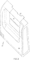
- An access door or cover 30 is mounted to the body 28 and movable between a closed position ( Fig. 3 ) and an open position ( Fig. 4 ), as will be described in greater detail.
- the illustrated access door 30 is hingedly connected to the body 28 of the cutter accessory 22, which allows the access door 30 to move between its closed and open positions by pivotal movement, but it is also within the scope of the present disclosure for the access door 30 to move between its closed and open positions in a different manner (e.g., by sliding or translational movement). It is also within the scope of the present disclosure for the access door 30 to be detached to move it from the closed position to the open position.
- the functionality of the cutter accessory 22 preferably depends upon the position of the access door 30.
- the cutter accessory 22 may be in an operative or functional state when the access door 30 is in its closed position ( Fig. 3 ) and in an inoperative or partial-functionality state when the access door 30 is in its open position ( Fig. 4 ).
- the cutter accessory 22 may be provided with a controller (e.g., a microprocessor) that is programmed with an active state (for when the access door 30 is in its closed position) and an inactive state (for when the access door 30 is in its open position).
- a controller e.g., a microprocessor
- an active state for when the access door 30 is in its closed position
- an inactive state for when the access door 30 is in its open position
- FIG. 5 shows an exemplary electrical circuit 32 by which the controller 34 of the cutter accessory 22 may be electrically coupled to a door sensor or interlock open switch 36, which monitors the position of the access door 30, thereby allowing the controller 34 to determine which state it should be in.
- the electrical circuit 32 will be described in greater detail herein.
- Fig. 6 illustrates a protocol that may be executed by the controller 34 when the access door 30 is in its open position or during an error condition, which will be described in greater detail.
- the controller 34 may transmit a signal to the printing device 10 (e.g., to instruct the printing device 10 to move to an inoperative or partial-functionality state and/or to display an image on the display screen 16).
- the cutter accessory 22 may be provided with one or more cables 38 ( Fig. 7 ) to electrically couple the cutter accessory 22 to the printing device 10, which may provide the cutter accessory 22 with power and/or allow the cutter accessory 22 and the printing device 10 to communicate with each other.
- the cutter accessory 22 may be electrically uncoupled from the printing device 10, in which case the cutter accessory 22 may include an independent power source and may communicate wirelessly with the printing device 10 (either directly or through a separate system controller).
- a slot 40 may be defined therein, with the slot 40 being configured and oriented to receive the printed material that issues from the opening 14 of the printed device 10. Accordingly, the slot 40 may be at least partially aligned with the opening 14 of the printed device 10 when the cutter accessory 22 is mounted to the printing device 10, with the access door 30 in the closed position, as in Fig. 2 .
- a cutting blade 42 ( Fig. 7 ) is movably mounted to the body 28 of the cutter accessory 22.
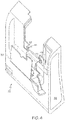
- At least one cam 44 (illustrated in Figs. 4 and 7 as two cams) is associated with the cutting blade 42 and operable to move the cutting blade 42 with respect to the slot 40.
- the cams 44 may be rotated under control of the controller 34 to move the cutting blade 42 in a reciprocating up-and-down motion (in the orientation of Fig. 7 ) to cut printed material positioned within the slot 40.
- the cutting blade 42 and/or cams 44 may be differently configured, positioned, and/or oriented and/or move in a different manner to cut the printed material to size.
- the controller 34 only instructs the cams 44 to move the cutting blade 42 when the access door 30 is in its closed position.
- the controller 34 is in its inactive state and does not instruct the cams 44 to move the cutting blade 42.
- the cams 44 may be manually operated to service the cutter accessory 22.
- the cams 44 may be configured and oriented such that they may be accessed when the access door 30 is in its open condition ( Fig.4 ).
- the cams 44 are covered or otherwise inaccessible when the access door 30 is in its closed condition ( Fig. 3 ) to prevent the cams 44 from being manually manipulated during normal operation of the printing system 24.
- each cam 44 includes an exposed surface or portion 46 ( Fig. 4 ) that faces away from the printing device 10 when the cutter accessory 22 is mounted to the printing device 10.
- Each exposed surface 46 is configured to accommodate a tool (e.g., by defining a socket that can receive the end of a hex key or Allen key) that may be used to manually rotate the associated cam 44 when the access door 30 is in its open position.
- a tool e.g., by defining a socket that can receive the end of a hex key or Allen key
- each exposed surface 46 may be configured to allow for the associated cam 44 to be rotated using one or more digits (e.g., by pressing a finger against the exposed surface 46 and moving the finger in a way that rotates the cam 44 or gripping an extension or formation of the exposed surface 46).
- Rotating the cam 44 causes the cutting blade 42 to also move, which may be necessary to free printed material that has become jammed or caught on the cutting blade 42.
- the access door 30 may be closed, which causes the controller 34 to determine whether the cutter accessory 34 is in condition for normal operation ( Fig. 6 ).
- cutter accessory 22 of Figs. 3 and 4 is merely exemplary and that a cutter accessory according to the present disclosure may be differently configured without departing from the scope of the present disclosure.
- the cutter accessory may be differently configured, include additional components (e.g., a display screen), and/or have additional functionality.
- the printing system 24 is ready for normal operation.
- a user instructs the printing device 10 (e.g., using the user interface 18) or the printing device 10 otherwise receives a command (e.g., via the antenna 20) to apply print to the substrate material.
- the substrate material is moved through the interior of the printing device 10, with print being applied to a portion of it. At least the printed portion of the substrate material exits the printing device 10 via the opening 14 and passes into the slot 40 of the cutter accessory 22.
- the cam or cams 44 of the cutter accessory 22 are operated under command of the controller 34 to move the cutting blade 42 to cut the substrate material to size as it passes through the slot 40, resulting in a properly sized unit or piece of printed material.
- the controllers of the cutter accessory 22 and the printing device 10 may communicate with each other to coordinate the actions of the printing device 10 and the cutter accessory 22.
- they may each communicate with a separate system controller that monitors and coordinates the actions of the printing device 10 and the cutter accessory 22.
- Error/Open Door Condit ion In the event of an error (e.g., if the substrate material becomes stuck within the printing device 10), normal operation of the printing system 24 may be temporarily interrupted.
- An error condition may be diagnosed by the any of the controllers associated with the printing system 24 according to any suitable approach (e.g., by electrically coupling a sensor that monitors the expected movement of the cams 44 and/or the cutting blade 42 to the controller 34 of the cutter accessory 22). If the printing system 24 includes more than one controller, then the controller that diagnoses an error condition may alert the other controller(s) to move all of the necessary components to an inoperative or partial-functionality state (e.g., to prevent additional substrate material from issuing from the printing device 10 if the cutting blade 42 is jammed).
- the printing device 10 and/or the cutter accessory 22 has a display screen (as in the illustrated embodiment, in which the printing device 10 includes a display screen 16), at least one image may be displayed to indicate an error condition.
- the image may be a letter or letters, a symbol or icon or pictogram, a change in color and/or brightness, or any combination thereof and may be accompanied by an audible alert to draw the attention of a user or service technician to the display screen.
- the image may indicate the occurrence of an error, identify the nature and/or location of the error, and/or offer suggested corrective actions to take to address the error.
- the display screen 16 may instruct a user to open the access door 30 of the cutter accessory 22.
- the cutter accessory 22 may be provided with an interlock that prevents the controller 34 from causing the cams 44 to move while the access door 30 is in its open position by placing the controller 34 in an inactive state.
- this interlock may include a door sensor or interlock open switch 36 that is associated with the access door 30.
- Fig. 5 shows an exemplary circuit 32 that may be used to electrically couple the door sensor 36 to the controller 34, in which the door sensor 36 is driven with input voltage 48 and transmits an output or signal 50, which represents the position of the access door 30.
- the output 50 has a low voltage state (equivalent to a digital or binary 0) when the access door 30 is in its closed position and a high voltage state (equivalent to a digital or binary 1) when the access door 30 is in its open position.
- a low voltage state equivalent to a digital or binary 0
- a high voltage state equivalent to a digital or binary 1
- the nature of the output 50 from the door sensor 36 may be reversed, with its low voltage state representing the access door 30 being in its open position and its high voltage state representing the access door 30 being in its closed position, as will be described in greater detail.
- the output 50 from the door sensor 36 is an input to an AND gate 52, with a diode 54 and a resistor 56 being electrically coupled to the output 50. If provided, the diode 54 may prevent excessive positive or negative voltages, while the resistor 56 may prevent unnecessary ringing or echoes on the conductor between the door sensor 36 and the AND gate 52.
- the AND gate 52 receives a second input 58, which may be provided with an associated resistor 60 to prevent static voltages from impacting the result value.
- the second input 58 may be a ground input to the AND gate, with the second input 58 being at a high voltage state (equivalent to a digital or binary 1).
- the second input 58 may represent some other source and/or provide some other function, as will be described in greater detail.
- the AND gate 52 may be configured and function according to conventional design, by only outputting an output or signal 62 with a high voltage state (equivalent to a digital or binary 1) when both of its inputs 50 and 58 are at a high voltage state (i.e., when the AND gate 52 receives two inputs 50 and 58 that are equivalent to a digital or binary 1).
- the output 62 from the AND gate 52 may only be at a high voltage state when the access door 30 is in its open position.
- the output 62 from the AND gate 52 is fed into the controller 34, which may use the output 62 as the basis for (or at least a factor in) determining whether to operate in its active state or its inactive state.
- the controller 34 may be programmed such that, when the output 62 of the AND gate 52 is at a low voltage state (i.e., when the access door 30 is in its closed position), the controller 34 is in its active state, in which the controller 34 may drive the cams 44 to move the cutting blade 42.
- the controller 34 may be further programmed such that, when the output 62 of the AND gate 52 is at a high voltage state (i.e., when the access door 30 is in its open position), the controller 34 is in an inactive state, in which the controller 34 may not drive the cams 44 to move the cutting blade 42.
- the cutting blade 42 is only moved under command of the controller 34 when the access door 30 is closed, which prevents the cutting blade 42 from being driven during maintenance.
- a circuit that is comparable to the circuit 32 of Fig. 5 may be used to electrically couple the controller 34 with one or more sensors that monitor the operation of one or more components of the printing system 24 (e.g., the cams 44). If one of these sensors transmits a signal to the controller 34 that is indicative of an error condition (e.g., the cams 44 not rotating when instructed by the controller 34), then the controller 34 may transition to its inactive state, similar to the way in which the controller 34 transitions to its inactive state when the access door 30 is opened. Thus, by such a configuration, the controller 34 only allows normal operation of the cutter accessory 22 when the access door 30 is closed and the various components of the printing system 24 are functioning properly.
- the door and error monitoring functions may be incorporated into a single circuit of the type shown in Fig. 5 .
- the output 50 of the door sensor 36 is reversed compared to the previously described embodiment, such that the output 50 has a high voltage state (equivalent to a digital or binary 1) when the access door 30 is in its closed position and a low voltage state (equivalent to a digital or binary 0) when the access door 30 is in its open position.
- the second input 58 of the AND gate 52 comes from one or more sensors that monitor the operation of one or more components of the printing system 24.
- the second input 58 may be at a high voltage state (equivalent to a digital or binary 1) when the monitored component(s) of the printing system 24 are operating properly and at a low voltage state (equivalent to a digital or binary 0) when the component(s) of the printing system 24 are not operating properly (e.g., in the event that the cams 44 and/or cutting blade 42 becomes jammed). It is also within the scope of the present disclosure for the second input 58 to be associated only with sensors that monitor the operation of the cutter accessory 22, with the controller 34 receiving a separate input that is indicative of normal operation or an error condition of the printing device 10.
- the AND gate 52 may be configured and function according to conventional design, such that the output 62 from the AND gate 52 may only be at a high voltage state when both of its inputs 50 and 58 are at a high voltage state (i.e., when the access door 30 is in its closed position and the components of the printing system 24 are operating properly). As describe previously, the output 62 from the AND gate 52 is fed into the controller 34, which may use the output 62 as the basis for (or at least a factor in) determining whether to operate in its active state or its inactive state.
- the controller 34 may be programmed such that, when the output 62 of the AND gate 52 is at a high voltage state (i.e., when the access door 30 is in its closed position and the components of the printing system 24 are operating properly), the controller 34 is in its active state, in which the controller 34 may drive the cams 44 to move the cutting blade 42.
- the controller 34 may be further programmed such that, when the output 62 of the AND gate 52 is at a low voltage state (i.e., when the access door 30 is in its open position and/or the components of the printing system 24 are not operating properly), the controller 34 is in an inactive state, in which the controller 34 may not drive the cams 44 to move the cutting blade 42.
- the cutting blade 42 is only moved under command of the controller 34 when the access door 30 is closed and the printing system 24 is operating properly, which prevents the cutting blade 42 from being driven during maintenance and during an error condition (which could damage the cutter accessory 22).
- the controller 34 of the cutter accessory 22 may execute a protocol of the type shown in Fig. 6 .
- the controller 34 monitors or is informed of the access door 30 being open or the existence of an error condition, which is represented at 64. This stage may correspond to the functionality represented in Fig. 5 , in which the controller 34 enters an inactive state when the access door 30 is open and/or there is an error condition.
- controller 34 may be advantageous to provide the controller 34 with additional functionality, such as the ability to distinguish between the reason for its inactive state (i.e., determining whether the access door 30 is open and there is no error condition, there is an error condition and the access door 30 is closed, or the access door 30 is open and there is an error condition), which would allow the controller 34 to transmit a variety of different signals to the printing device 10.
- the controller 34 determines that the access door 30 is open and/or there is an error condition (represented in Fig. 6 as a "YES" decision)
- the controller 34 moves from its active state into its inactive state (as described previously), which is represented in Fig. 6 at 66.
- the controller 34 halts operation of the cams 44 and transmits a signal to instruct the printing device 10 (either directly or via a separate system controller) to move from an operative or functional state to an inoperative or partial-functionality state.
- the signal may include additional information about the nature of the interruption of normal operation.
- the signal may be an "open door signal” (indicating that the access door 30 is open and there is no error condition), an "error signal” (indicating that there is an error condition and the access door 30 is closed), or a “combined interruption” signal (indicating that the access door 30 is open and there is an error condition).
- the cutter accessory 22 may transition from its inactive state to its active state (as described previously), thereby transmitting a "ready signal" to the printing device 10 (either directly or through a separate system controller) that it may return to its operative or functional state.
- Fig. 8 showing an exemplary protocol that may be executed by a controller of the printing device 10 during an error or open door condition, at least partially concurrent with the Fig. 6 protocol carried out by the controller 34 of the cutter accessory 22.
- the controller of the printing device 10 checks for a signal from the cutter accessory 22 or a separate system controller that signifies an error or open door condition.
- the printing device 10 moves from an operative or functional state to an inoperative or partial-functionality state.
- transitioning from the operative or functional state to the inoperative or partial-functionality state represented in Fig.
- operation of the various components of the printing device 10 may be paused or halted to prevent the creation of additional printed material.
- the signal received from the controller 34 of the cutter accessory 22 may also cause at least one image to be displayed on the display screen 16 of the printing device 10 (if provided), as described previously, which may vary depending on the nature of the signal.
- an "error signal” (described previously) may result in the display screen 16 identifying the error and instructing a user or service technician to open the access door 30 to correct the error.
- An "open door” signal (described previously) may result in the display screen 16 instructing a user or service technician to close the access door 30 to resume normal operation of the printing system 24.
- a “combined interruption” signal (described previously) may result in the display screen 16 providing a user or service technician with instructions for correcting the error and instructing them to close the access door 30 upon carrying out the recommended process.
- the printing device 10 may perform any necessary actions as part of the recovery process, such as providing additional messages to a user or service technician via the display screen 16 (represented in Fig. 8 at 74).
- the controller of the printing device 10 also checks for the "ready signal" from the cutter accessory 22 or a separate system controller, which indicates that the error condition (if any) has been addressed and the access door 30 has been moved to its closed position (represented in Fig. 8 at 76). If the signal received by the controller of the printing device 10 indicates that the access door 30 is still open and/or there remains an error condition (represented in Fig. 8 by a "NO" decision), the printing device 10 returns to stage 74 and performs any necessary actions as part of the recovery process.
- the printing device 10 may transition from its inoperative or partial-functionality state to its operative or functional state. This causes the protocol of Fig. 8 to repeat, with the controller of the printing device 10 waiting to receive a signal indicating an error or open door condition.
- the controller of the printing device 10 may be capable of instructing the cutter accessory 22 to pause its operation in the event of an error in the operation of the printing device 10 (if the cutter accessory 22 does not itself detect such an error due to a disruption in the expected flow of the substrate material out of the printing device 10). Accordingly, either controller may take the lead in resolving an error condition, depending on whether the error arises in operation of a component of the printing device 10 or the cutter accessory 22.
- the access door 30 While the access door 30 is typically opened only to resolve an error condition, it may be opened at any time, at which point the controller 34 of the cutter accessory 22 will be placed into its inactive state, as described above. If the controller 34 does not register an error condition, then it may automatically transition from its inactive state to its active state upon the access door 30 being closed, although it is also within the scope of the present disclosure for the controller 34 to be programmed to execute a preliminary error check upon the access door 30 moving to its closed position to ensure that the printing device 10 is also ready for normal operation.
- One of the reasons for opening the access door 30 in the absence of an error condition is to perform regular, periodic maintenance on the cams 44 and/or the cutting blade 44. It may be advantageous to perform regular, periodic maintenance on the components of the cutter accessory 22 to better ensure consistent performance of the printing system 24 as intended. Maintenance of the printing system 24 by necessity requires down time until the maintenance is complete, but the configuration of the cutter accessory 22 is such that minimal down time is required to perform routine maintenance.
- Fig. 9 is an exemplary protocol that may be carried out by the controller 34 of the cutter accessory 22 to determine whether maintenance is recommended.
- the process begins when a user or service technician requests information regarding the number of times that the cutting blade 42 has been moved at the command of the controller 34 (represented in Fig. 9 at 78).
- the controller 34 may be programmed to count and keep track of the number of times that the cutting blade 42 has been moved at the command of the controller 34, so it may access this count at stage 80.
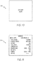
- the controller 34 may inform the user or service technician of the count by transmitting a signal to the printing device 10 to display at least one image 82 that is indicative of the count on the display screen 16, as shown in Fig. 10 .
- the count on the display stream could appear as an informative message to the user during normal operation of the device. When the number of cuts reaches the service level a message can briefly appear to the user to inform them of the need to provide maintenance. This count can be reset after the cutter door is opened providing access for service.
- the controller 34 may instruct the printing device 10 to generate a unit or piece of printed material 84 ( Fig. 11 ) with at least one image that is indicative of the count and may also include additional diagnostic information.
- the controller 34 may compare the count to a preselected number (represented in Fig. 9 at 86).
- the preselected number may correspond to the recommended number of times that the cutting blade 42 is moved under command of the controller 34 before periodic maintenance is performed.
- the preselected number is 100,000, but any other preselected number may be used without departing from the scope of the present disclosure.
- the controller 34 may reset the count and recommend that maintenance be performed on the cutter accessory 22 (represented in Fig. 9 at 90).
- the user or service technician may service the cutter accessory 22 by opening the access door 30 to expose the cams 44.
- the user or service technician then uses a cotton swab to add grease to the cams 44.
- the cams 44 can be rotated manually to expose all the surface area to facilitate the maintenance process.
- the access door 30 is then closed, which causes the process of Fig. 9 to be exited.
- the controller 34 may be programmed to recognize when the cut count equals or exceeds the preselected number. When the controller 34 determines that the cut count meets or exceeds the preselected number, it may alert a user or service technician by instructing the printing device 10 to generate a piece or unit of printed material with this recommendation and/or to display the recommendation on the display screen 16 or may otherwise alert a user or service technician that periodic maintenance is recommended.
Landscapes
- Life Sciences & Earth Sciences (AREA)
- Forests & Forestry (AREA)
- Engineering & Computer Science (AREA)
- Mechanical Engineering (AREA)
- Handling Of Sheets (AREA)
Description
- The present subject matter relates to printing systems. More particularly, the present subject matter relates to cutter accessories that may be removably mounted to a printing device.
- Printing devices, such as thermal printers, are used to generate printed material. If the substrate of the printed material is provided on a roll or otherwise not provided in discrete units or pieces (e.g., individual sheets or labels), then the printed material must be cut to size. Typically, the printing device includes a built-in cutter, which cuts the substrate to size after print has been applied to the substrate. While built-in cutters may provide adequate functionality, they may also result in various disadvantages when maintenance is required. For example, if the substrate becomes caught or jammed in the cutter while passing through the printing device or if the cutter otherwise becomes inoperative, then the cutter must be accessed to correct the error. Traditional printing devices require several guard plates to be removed to access the built-in cutter, which increases the time that the printing device is inoperative. Accordingly, it would be advantageous to provide a printing system with a cutter that may be more easily serviced.
-
EP 2 106 887 A1 discloses a device consisting of an electric motor with connection to the check and on/off card and with a shaft connected to an eccentric cam having a pin to be inserted into a shutter with blade. Counterposed to the blade an immovable blade is present, onto staggered planes, with said blades place near a slot of getting out of the printed ticket so to cut the same ticket. A body then determines an anti-breaking and containment structure of the shutter, which is kept inside a sliding seat by a spring. - Therefore,
EP 2 106 887 A1 discloses a cutter accessory for use in combination with a printing device, comprising a body configured to be mounted onto a printing device; a slot configured to receive printed material from the printing device; a cutting blade movably mounted to the body; and at least one cam associated with the cutting blade and operable to move the cutting blade with respect to the slot to cut the printed material from the printing device. - In an aspect, there is provided a printing system, which includes a printing device and a cutter accessory. The printing device includes a housing and an opening, which is defined in the housing and configured to issue printed material. The cutter accessory includes a body that is mounted to the housing of the printing device. An access door is mounted to the body and movable between a closed position and an open position. A slot is defined in the access door and at least partially aligned with the opening of the printing device to receive printed material issuing from the opening of the printing device when the access door is in the closed position. A cutting blade is movably mounted to the body, with at least one cam being associated with the cutting blade. The at least one cam is operable to move the cutting blade with respect to the slot to cut the printed material issuing from the printing device and is accessible when the access door is in the open position, but not accessible when the access door is in the closed position.
-
-
Fig. 1 is a front perspective view of a printing device; -
Fig. 2 is a front perspective view of a printing system incorporating the printing device ofFig. 1 ; -
Fig. 3 is a front perspective view of a cutter accessory of the printing system ofFig. 2 , with an access door of the cutter accessory being in a closed position; -
Fig. 4 is a front perspective view of the cutter accessory ofFig. 3 , with the access door in an open position; -
Fig. 5 is a diagrammatic view of an electrical circuit that electrically couples a controller of the cutter accessory to a door sensor; -
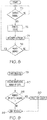
Fig. 6 is a diagrammatic view of a protocol executed by the controller of the cutter accessory when the access door is in the open position or in the event of an error condition; -
Fig. 7 is a rear perspective view of the cutter accessory ofFig. 3 ; -
Fig. 8 is a diagrammatic view of a protocol executed by a controller of the printing device when the access door of the cutter accessory is open or in the event of an error condition; -
Fig. 9 is a diagrammatic view of a protocol executed by the controller of the cutter accessory to determine whether periodic maintenance is required; -
Fig. 10 illustrates an exemplary image that may be displayed on a display screen of the printing device ofFig. 1 to indicate the number of times that the cutter accessory has cut printed material issued by the printing device; and -
Fig. 11 illustrates an exemplary unit or piece of printed material that may be issued by the printing device to indicate the number of times that the cutter accessory has cut printed material issued by the printing device. - As required, detailed embodiments of the present invention are disclosed herein; however, it is to be understood that the disclosed embodiments are merely exemplary of the invention, which may be embodied in various forms. Therefore, specific details disclosed herein are not to be interpreted as limiting, but merely as a basis for the claims and as a representative basis for teaching one skilled in the art to variously employ the present invention in virtually any appropriate manner.
- Printing Device. To address the disadvantages of known systems, it has been found to be convenient to provide a cutter accessory that may be removably mounted to a printing device not having a built-in cutter.
Fig. 1 shows such a printing device 10 configured as a thermal printer, but it is also within the scope of the present disclosure for the printing device 10 to incorporate other printing technology (e.g., laser or inkjet). It should also be understood that the illustrated printing device 10 is merely exemplary and that the configuration may vary without departing from the scope of the present disclosure. - The illustrated printing device 10 includes an enclosure or
housing 12, which may be formed of any suitable material or materials (e.g., a generally rigid metal material and/or generally rigid plastic material). Thehousing 12 contains various components, which may include a supply of substrate material, a mechanism for applying print to the substrate material, and a mechanism for moving the substrate material through the interior of thehousing 12 and out of thehousing 12 via anopening 14, where it exits the printing device 10 as printed material. The printing device 10 may also include a controller (e.g., a microprocessor) that controls the operation of the other components of the printing device 10. The printing device 10 may include assorted other components and functionality (e.g., adisplay screen 16 anduser interface 18 and anantenna 20 for wireless communication) without departing from the scope of the present disclosure. - Cutter Accessory. The printing device 10 may be combined with a cutter accessory 22 (
Figs. 2 and3 ) to provide a printing system 24 (Fig. 2 ). Thecutter accessory 22 is configured to receive printed material from the printing device 10 for cutting the printed material to size, so the way in which thecutter accessory 22 is mounted to the printing device 10 depends at least in part upon the position of theopening 14 from which printed material exits the printing device 10. In the illustrated embodiment, theopening 14 is defined in a front face orfront panel 26 of the printing device 10 (Fig. 1 ), such that thecutter accessory 22 may be mounted to thefront panel 26 of the printing device 10 to receive the printed material. In other embodiments, in which printed material may issue from the printing device at a different location, the associated cutter accessory may be differently configured for a different mounting arrangement. It may be advantageous for thecutter accessory 22 to be removably mounted to the printing device 10 (e.g., being fastened to the printing device 10 by screws or the like), although it is also within the scope of the present disclosure for thecutter accessory 22 to be fixedly secured to the printing device 10 (e.g., by a welding operation). - The
cutter accessory 22 has a body orbase 28 that may be contoured or configured to match the portion of theprinting device housing 12 adjacent to theopening 14. For example, in the illustrated embodiment, in which printed material issues from anopening 14 defined in thefront panel 26 of the printing device 10, the configuration and shape of thebody 28 of thecutter accessory 22 may be informed by the configuration of the portion of thefront panel 26 of the printing device 10 in the vicinity of theopening 14. Thebody 28 of thecutter accessory 22 may be formed of any suitable material or materials, such as a generally rigid metal material and/or a generally rigid plastic material. - An access door or
cover 30 is mounted to thebody 28 and movable between a closed position (Fig. 3 ) and an open position (Fig. 4 ), as will be described in greater detail. The illustratedaccess door 30 is hingedly connected to thebody 28 of thecutter accessory 22, which allows theaccess door 30 to move between its closed and open positions by pivotal movement, but it is also within the scope of the present disclosure for theaccess door 30 to move between its closed and open positions in a different manner (e.g., by sliding or translational movement). It is also within the scope of the present disclosure for theaccess door 30 to be detached to move it from the closed position to the open position. - The functionality of the
cutter accessory 22 preferably depends upon the position of theaccess door 30. As will be described in greater detail, thecutter accessory 22 may be in an operative or functional state when theaccess door 30 is in its closed position (Fig. 3 ) and in an inoperative or partial-functionality state when theaccess door 30 is in its open position (Fig. 4 ). To that end, thecutter accessory 22 may be provided with a controller (e.g., a microprocessor) that is programmed with an active state (for when theaccess door 30 is in its closed position) and an inactive state (for when theaccess door 30 is in its open position). Alternately, when the door is in the open state the driver could disengage the knife motor preventing accidental firing of the knife while it is being serviced.Fig. 5 shows an exemplaryelectrical circuit 32 by which thecontroller 34 of thecutter accessory 22 may be electrically coupled to a door sensor or interlockopen switch 36, which monitors the position of theaccess door 30, thereby allowing thecontroller 34 to determine which state it should be in. Theelectrical circuit 32 will be described in greater detail herein. -
Fig. 6 illustrates a protocol that may be executed by thecontroller 34 when theaccess door 30 is in its open position or during an error condition, which will be described in greater detail. As a part of this protocol, thecontroller 34 may transmit a signal to the printing device 10 (e.g., to instruct the printing device 10 to move to an inoperative or partial-functionality state and/or to display an image on the display screen 16). Thecutter accessory 22 may be provided with one or more cables 38 (Fig. 7 ) to electrically couple thecutter accessory 22 to the printing device 10, which may provide thecutter accessory 22 with power and/or allow thecutter accessory 22 and the printing device 10 to communicate with each other. In an alternative embodiment, thecutter accessory 22 may be electrically uncoupled from the printing device 10, in which case thecutter accessory 22 may include an independent power source and may communicate wirelessly with the printing device 10 (either directly or through a separate system controller). - Turning back now to the configuration of the
access door 30, aslot 40 may be defined therein, with theslot 40 being configured and oriented to receive the printed material that issues from theopening 14 of the printed device 10. Accordingly, theslot 40 may be at least partially aligned with theopening 14 of the printed device 10 when thecutter accessory 22 is mounted to the printing device 10, with theaccess door 30 in the closed position, as inFig. 2 . - A cutting blade 42 (
Fig. 7 ) is movably mounted to thebody 28 of thecutter accessory 22. At least one cam 44 (illustrated inFigs. 4 and7 as two cams) is associated with thecutting blade 42 and operable to move thecutting blade 42 with respect to theslot 40. When theaccess door 30 is in its closed position (Fig. 3 ), thecams 44 may be rotated under control of thecontroller 34 to move thecutting blade 42 in a reciprocating up-and-down motion (in the orientation ofFig. 7 ) to cut printed material positioned within theslot 40. In other embodiments, thecutting blade 42 and/orcams 44 may be differently configured, positioned, and/or oriented and/or move in a different manner to cut the printed material to size. - The
controller 34 only instructs thecams 44 to move thecutting blade 42 when theaccess door 30 is in its closed position. When theaccess door 30 is in its open position, thecontroller 34 is in its inactive state and does not instruct thecams 44 to move thecutting blade 42. While thecontroller 34 does not operate thecams 44 when it is in its inactive state, thecams 44 may be manually operated to service thecutter accessory 22. For improved maintenance, thecams 44 may be configured and oriented such that they may be accessed when theaccess door 30 is in its open condition (Fig.4 ). Preferably, thecams 44 are covered or otherwise inaccessible when theaccess door 30 is in its closed condition (Fig. 3 ) to prevent thecams 44 from being manually manipulated during normal operation of the printing system 24. By such a configuration, an operator or service technician can service thecams 44 by simply opening the access door 30 (thereby placing thecontroller 34 into an inactive state), rather than requiring several guard plates to be removed (as in typically required with built-in cutters). - In the illustrated embodiment, each
cam 44 includes an exposed surface or portion 46 (Fig. 4 ) that faces away from the printing device 10 when thecutter accessory 22 is mounted to the printing device 10. Each exposedsurface 46 is configured to accommodate a tool (e.g., by defining a socket that can receive the end of a hex key or Allen key) that may be used to manually rotate the associatedcam 44 when theaccess door 30 is in its open position. Alternatively, rather than being configured to accommodate a tool, each exposedsurface 46 may be configured to allow for the associatedcam 44 to be rotated using one or more digits (e.g., by pressing a finger against the exposedsurface 46 and moving the finger in a way that rotates thecam 44 or gripping an extension or formation of the exposed surface 46). - Rotating the
cam 44 causes thecutting blade 42 to also move, which may be necessary to free printed material that has become jammed or caught on thecutting blade 42. After at least one of thecams 44 has been manually manipulated or other corrective action has been taken (e.g., reorienting printed material passing from the printing device 10 through the cutter accessory 22), theaccess door 30 may be closed, which causes thecontroller 34 to determine whether thecutter accessory 34 is in condition for normal operation (Fig. 6 ). - It should be understood that the
cutter accessory 22 ofFigs. 3 and4 is merely exemplary and that a cutter accessory according to the present disclosure may be differently configured without departing from the scope of the present disclosure. For example, it is contemplated that the cutter accessory may be differently configured, include additional components (e.g., a display screen), and/or have additional functionality. - Normal Operation. When the
cutter accessory 22 is fully connected to the printing device 10, with theaccess door 30 in its closed position (Fig. 2 ), the printing system 24 is ready for normal operation. During normal operation, a user instructs the printing device 10 (e.g., using the user interface 18) or the printing device 10 otherwise receives a command (e.g., via the antenna 20) to apply print to the substrate material. The substrate material is moved through the interior of the printing device 10, with print being applied to a portion of it. At least the printed portion of the substrate material exits the printing device 10 via theopening 14 and passes into theslot 40 of thecutter accessory 22. - The cam or
cams 44 of thecutter accessory 22 are operated under command of thecontroller 34 to move thecutting blade 42 to cut the substrate material to size as it passes through theslot 40, resulting in a properly sized unit or piece of printed material. The controllers of thecutter accessory 22 and the printing device 10 may communicate with each other to coordinate the actions of the printing device 10 and thecutter accessory 22. Alternatively, rather than the printing device 10 and thecutter accessory 22 communicating with each other, they may each communicate with a separate system controller that monitors and coordinates the actions of the printing device 10 and thecutter accessory 22. - Error/Open Door Condit ion. In the event of an error (e.g., if the substrate material becomes stuck within the printing device 10), normal operation of the printing system 24 may be temporarily interrupted. An error condition may be diagnosed by the any of the controllers associated with the printing system 24 according to any suitable approach (e.g., by electrically coupling a sensor that monitors the expected movement of the
cams 44 and/or thecutting blade 42 to thecontroller 34 of the cutter accessory 22). If the printing system 24 includes more than one controller, then the controller that diagnoses an error condition may alert the other controller(s) to move all of the necessary components to an inoperative or partial-functionality state (e.g., to prevent additional substrate material from issuing from the printing device 10 if thecutting blade 42 is jammed). - If the printing device 10 and/or the
cutter accessory 22 has a display screen (as in the illustrated embodiment, in which the printing device 10 includes a display screen 16), at least one image may be displayed to indicate an error condition. The image may be a letter or letters, a symbol or icon or pictogram, a change in color and/or brightness, or any combination thereof and may be accompanied by an audible alert to draw the attention of a user or service technician to the display screen. The image may indicate the occurrence of an error, identify the nature and/or location of the error, and/or offer suggested corrective actions to take to address the error. - Access Door Monitoring. If the
cutter accessory 22 stops operating normally due to thecutting blade 42 becoming jammed, thedisplay screen 16 may instruct a user to open theaccess door 30 of thecutter accessory 22. As a safety feature, thecutter accessory 22 may be provided with an interlock that prevents thecontroller 34 from causing thecams 44 to move while theaccess door 30 is in its open position by placing thecontroller 34 in an inactive state. As described above and as shown inFig. 5 , this interlock may include a door sensor or interlockopen switch 36 that is associated with theaccess door 30.Fig. 5 shows anexemplary circuit 32 that may be used to electrically couple thedoor sensor 36 to thecontroller 34, in which thedoor sensor 36 is driven withinput voltage 48 and transmits an output or signal 50, which represents the position of theaccess door 30. In one embodiment, theoutput 50 has a low voltage state (equivalent to a digital or binary 0) when theaccess door 30 is in its closed position and a high voltage state (equivalent to a digital or binary 1) when theaccess door 30 is in its open position. In other embodiments, the nature of theoutput 50 from thedoor sensor 36 may be reversed, with its low voltage state representing theaccess door 30 being in its open position and its high voltage state representing theaccess door 30 being in its closed position, as will be described in greater detail. - In the
circuit 32 ofFig. 5 , theoutput 50 from thedoor sensor 36 is an input to an ANDgate 52, with adiode 54 and a resistor 56 being electrically coupled to theoutput 50. If provided, thediode 54 may prevent excessive positive or negative voltages, while the resistor 56 may prevent unnecessary ringing or echoes on the conductor between thedoor sensor 36 and the ANDgate 52. - The AND
gate 52 receives asecond input 58, which may be provided with an associated resistor 60 to prevent static voltages from impacting the result value. Thesecond input 58 may be a ground input to the AND gate, with thesecond input 58 being at a high voltage state (equivalent to a digital or binary 1). In other embodiments, thesecond input 58 may represent some other source and/or provide some other function, as will be described in greater detail. - The AND
gate 52 may be configured and function according to conventional design, by only outputting an output or signal 62 with a high voltage state (equivalent to a digital or binary 1) when both of itsinputs gate 52 receives twoinputs output 62 from the ANDgate 52 may only be at a high voltage state when theaccess door 30 is in its open position. - The
output 62 from the ANDgate 52 is fed into thecontroller 34, which may use theoutput 62 as the basis for (or at least a factor in) determining whether to operate in its active state or its inactive state. Thecontroller 34 may be programmed such that, when theoutput 62 of the ANDgate 52 is at a low voltage state (i.e., when theaccess door 30 is in its closed position), thecontroller 34 is in its active state, in which thecontroller 34 may drive thecams 44 to move thecutting blade 42. Thecontroller 34 may be further programmed such that, when theoutput 62 of the ANDgate 52 is at a high voltage state (i.e., when theaccess door 30 is in its open position), thecontroller 34 is in an inactive state, in which thecontroller 34 may not drive thecams 44 to move thecutting blade 42. Thus, by such a configuration, thecutting blade 42 is only moved under command of thecontroller 34 when theaccess door 30 is closed, which prevents thecutting blade 42 from being driven during maintenance. - It may be advantageous for the
controller 34 to also monitor whether the printing system 24 is experiencing an error condition. In one embodiment, a circuit that is comparable to thecircuit 32 ofFig. 5 may be used to electrically couple thecontroller 34 with one or more sensors that monitor the operation of one or more components of the printing system 24 (e.g., the cams 44). If one of these sensors transmits a signal to thecontroller 34 that is indicative of an error condition (e.g., thecams 44 not rotating when instructed by the controller 34), then thecontroller 34 may transition to its inactive state, similar to the way in which thecontroller 34 transitions to its inactive state when theaccess door 30 is opened. Thus, by such a configuration, thecontroller 34 only allows normal operation of thecutter accessory 22 when theaccess door 30 is closed and the various components of the printing system 24 are functioning properly. - In another embodiment, the door and error monitoring functions may be incorporated into a single circuit of the type shown in
Fig. 5 . In such an embodiment, theoutput 50 of thedoor sensor 36 is reversed compared to the previously described embodiment, such that theoutput 50 has a high voltage state (equivalent to a digital or binary 1) when theaccess door 30 is in its closed position and a low voltage state (equivalent to a digital or binary 0) when theaccess door 30 is in its open position. - In this embodiment, rather than being a ground input, the
second input 58 of the ANDgate 52 comes from one or more sensors that monitor the operation of one or more components of the printing system 24. Thesecond input 58 may be at a high voltage state (equivalent to a digital or binary 1) when the monitored component(s) of the printing system 24 are operating properly and at a low voltage state (equivalent to a digital or binary 0) when the component(s) of the printing system 24 are not operating properly (e.g., in the event that thecams 44 and/or cuttingblade 42 becomes jammed). It is also within the scope of the present disclosure for thesecond input 58 to be associated only with sensors that monitor the operation of thecutter accessory 22, with thecontroller 34 receiving a separate input that is indicative of normal operation or an error condition of the printing device 10. - The AND
gate 52 may be configured and function according to conventional design, such that theoutput 62 from the ANDgate 52 may only be at a high voltage state when both of itsinputs access door 30 is in its closed position and the components of the printing system 24 are operating properly). As describe previously, theoutput 62 from the ANDgate 52 is fed into thecontroller 34, which may use theoutput 62 as the basis for (or at least a factor in) determining whether to operate in its active state or its inactive state. In this embodiment, thecontroller 34 may be programmed such that, when theoutput 62 of the ANDgate 52 is at a high voltage state (i.e., when theaccess door 30 is in its closed position and the components of the printing system 24 are operating properly), thecontroller 34 is in its active state, in which thecontroller 34 may drive thecams 44 to move thecutting blade 42. Thecontroller 34 may be further programmed such that, when theoutput 62 of the ANDgate 52 is at a low voltage state (i.e., when theaccess door 30 is in its open position and/or the components of the printing system 24 are not operating properly), thecontroller 34 is in an inactive state, in which thecontroller 34 may not drive thecams 44 to move thecutting blade 42. Thus, by such a configuration, thecutting blade 42 is only moved under command of thecontroller 34 when theaccess door 30 is closed and the printing system 24 is operating properly, which prevents thecutting blade 42 from being driven during maintenance and during an error condition (which could damage the cutter accessory 22). - Cutter Accessory During Error/Open Door Condition. When the
access door 30 is open and/or thecutter accessory 22 is in an error condition, thecontroller 34 of thecutter accessory 22 may execute a protocol of the type shown inFig. 6 . In the exemplary protocol ofFig. 6 , thecontroller 34 monitors or is informed of theaccess door 30 being open or the existence of an error condition, which is represented at 64. This stage may correspond to the functionality represented inFig. 5 , in which thecontroller 34 enters an inactive state when theaccess door 30 is open and/or there is an error condition. It may be advantageous to provide thecontroller 34 with additional functionality, such as the ability to distinguish between the reason for its inactive state (i.e., determining whether theaccess door 30 is open and there is no error condition, there is an error condition and theaccess door 30 is closed, or theaccess door 30 is open and there is an error condition), which would allow thecontroller 34 to transmit a variety of different signals to the printing device 10. - When the
controller 34 determines that theaccess door 30 is open and/or there is an error condition (represented inFig. 6 as a "YES" decision), thecontroller 34 moves from its active state into its inactive state (as described previously), which is represented inFig. 6 at 66. Upon transitioning to its inactive state, thecontroller 34 halts operation of thecams 44 and transmits a signal to instruct the printing device 10 (either directly or via a separate system controller) to move from an operative or functional state to an inoperative or partial-functionality state. The signal may include additional information about the nature of the interruption of normal operation. For example, the signal may be an "open door signal" (indicating that theaccess door 30 is open and there is no error condition), an "error signal" (indicating that there is an error condition and theaccess door 30 is closed), or a "combined interruption" signal (indicating that theaccess door 30 is open and there is an error condition). - When the error condition (if any) has been addressed and the
access door 30 is moved to its closed position (represented inFig. 6 at 68), thecutter accessory 22 may transition from its inactive state to its active state (as described previously), thereby transmitting a "ready signal" to the printing device 10 (either directly or through a separate system controller) that it may return to its operative or functional state. This causes the protocol ofFig. 6 to repeat, with thecontroller 34 of thecutter accessory 22 monitoring whether theaccess door 30 is open and/or there is an error condition. - Printing Device During Error/Open Door Condition.
Fig. 8 showing an exemplary protocol that may be executed by a controller of the printing device 10 during an error or open door condition, at least partially concurrent with theFig. 6 protocol carried out by thecontroller 34 of thecutter accessory 22. Atstage 70 ofFig. 8 , the controller of the printing device 10 checks for a signal from thecutter accessory 22 or a separate system controller that signifies an error or open door condition. Upon receiving such a signal (represented inFig. 8 as a "YES" decision), the printing device 10 moves from an operative or functional state to an inoperative or partial-functionality state. In transitioning from the operative or functional state to the inoperative or partial-functionality state (represented inFig. 8 at 72), operation of the various components of the printing device 10 may be paused or halted to prevent the creation of additional printed material. At this time, the signal received from thecontroller 34 of thecutter accessory 22 may also cause at least one image to be displayed on thedisplay screen 16 of the printing device 10 (if provided), as described previously, which may vary depending on the nature of the signal. For example, an "error signal" (described previously) may result in thedisplay screen 16 identifying the error and instructing a user or service technician to open theaccess door 30 to correct the error. An "open door" signal (described previously) may result in thedisplay screen 16 instructing a user or service technician to close theaccess door 30 to resume normal operation of the printing system 24. A "combined interruption" signal (described previously) may result in thedisplay screen 16 providing a user or service technician with instructions for correcting the error and instructing them to close theaccess door 30 upon carrying out the recommended process. - While in its inoperative or partial-functionality state, the printing device 10 may perform any necessary actions as part of the recovery process, such as providing additional messages to a user or service technician via the display screen 16 (represented in
Fig. 8 at 74). During this time, the controller of the printing device 10 also checks for the "ready signal" from thecutter accessory 22 or a separate system controller, which indicates that the error condition (if any) has been addressed and theaccess door 30 has been moved to its closed position (represented inFig. 8 at 76). If the signal received by the controller of the printing device 10 indicates that theaccess door 30 is still open and/or there remains an error condition (represented inFig. 8 by a "NO" decision), the printing device 10 returns to stage 74 and performs any necessary actions as part of the recovery process. Otherwise, if the signal received by the controller of the printing device 10 is the "ready signal" and indicates that theaccess door 30 has been closed and that the error condition has been successfully resolved (i.e., upon thecontroller 34 of thecutter accessory 22 moving to its active state), then the printing device 10 may transition from its inoperative or partial-functionality state to its operative or functional state. This causes the protocol ofFig. 8 to repeat, with the controller of the printing device 10 waiting to receive a signal indicating an error or open door condition. - In another embodiment, in addition to the
controller 34 of thecutter accessory 22 being capable of instructing the printing device 10 to pause its operation (as in the protocol ofFig. 8 ), the controller of the printing device 10 may be capable of instructing thecutter accessory 22 to pause its operation in the event of an error in the operation of the printing device 10 (if thecutter accessory 22 does not itself detect such an error due to a disruption in the expected flow of the substrate material out of the printing device 10). Accordingly, either controller may take the lead in resolving an error condition, depending on whether the error arises in operation of a component of the printing device 10 or thecutter accessory 22. - Periodic Maintenance. While the
access door 30 is typically opened only to resolve an error condition, it may be opened at any time, at which point thecontroller 34 of thecutter accessory 22 will be placed into its inactive state, as described above. If thecontroller 34 does not register an error condition, then it may automatically transition from its inactive state to its active state upon theaccess door 30 being closed, although it is also within the scope of the present disclosure for thecontroller 34 to be programmed to execute a preliminary error check upon theaccess door 30 moving to its closed position to ensure that the printing device 10 is also ready for normal operation. - One of the reasons for opening the
access door 30 in the absence of an error condition is to perform regular, periodic maintenance on thecams 44 and/or thecutting blade 44. It may be advantageous to perform regular, periodic maintenance on the components of thecutter accessory 22 to better ensure consistent performance of the printing system 24 as intended. Maintenance of the printing system 24 by necessity requires down time until the maintenance is complete, but the configuration of thecutter accessory 22 is such that minimal down time is required to perform routine maintenance. -
Fig. 9 is an exemplary protocol that may be carried out by thecontroller 34 of thecutter accessory 22 to determine whether maintenance is recommended. The process begins when a user or service technician requests information regarding the number of times that thecutting blade 42 has been moved at the command of the controller 34 (represented inFig. 9 at 78). Thecontroller 34 may be programmed to count and keep track of the number of times that thecutting blade 42 has been moved at the command of thecontroller 34, so it may access this count atstage 80. - The
controller 34 may inform the user or service technician of the count by transmitting a signal to the printing device 10 to display at least one image 82 that is indicative of the count on thedisplay screen 16, as shown inFig. 10 . The count on the display stream could appear as an informative message to the user during normal operation of the device. When the number of cuts reaches the service level a message can briefly appear to the user to inform them of the need to provide maintenance. This count can be reset after the cutter door is opened providing access for service. Alternatively, or additionally, thecontroller 34 may instruct the printing device 10 to generate a unit or piece of printed material 84 (Fig. 11 ) with at least one image that is indicative of the count and may also include additional diagnostic information. - Upon reporting the count to the user or service technician, the
controller 34 may compare the count to a preselected number (represented inFig. 9 at 86). The preselected number may correspond to the recommended number of times that thecutting blade 42 is moved under command of thecontroller 34 before periodic maintenance is performed. In the illustrated embodiment, the preselected number is 100,000, but any other preselected number may be used without departing from the scope of the present disclosure. - If the count is less than preselected number (represented in
Fig. 9 by a "NO" decision), then the process is exited (represented inFig. 9 at 88). On the other hand, if the count is greater than the preselected number (represented inFig. 9 by a "YES" decision), then thecontroller 34 may reset the count and recommend that maintenance be performed on the cutter accessory 22 (represented inFig. 9 at 90). The user or service technician may service thecutter accessory 22 by opening theaccess door 30 to expose thecams 44. The user or service technician then uses a cotton swab to add grease to thecams 44. Thecams 44 can be rotated manually to expose all the surface area to facilitate the maintenance process. Theaccess door 30 is then closed, which causes the process ofFig. 9 to be exited. - In another embodiment, rather than relying upon a cut count to be requested by a user or service technician, the
controller 34 may be programmed to recognize when the cut count equals or exceeds the preselected number. When thecontroller 34 determines that the cut count meets or exceeds the preselected number, it may alert a user or service technician by instructing the printing device 10 to generate a piece or unit of printed material with this recommendation and/or to display the recommendation on thedisplay screen 16 or may otherwise alert a user or service technician that periodic maintenance is recommended.
Claims (13)
- A printing system (24), comprising:a printing device (10) comprising a housing (12) and an opening (14) defined in the housing (12) and configured to issue printed material; anda cutter accessory (22) comprisinga body (28) mounted to the housing (12) of the printing device (10),an access door (30) mounted to the body (12) and movable between a closed position and an open position,a slot (40) defined in the access door (30) and at least partially aligned with the opening (14) of the printing device (10) to receive printed material issuing from the opening (14) of the printing device (10) when the access door (30) is in the closed position,a cutting blade (42) movably mounted to the body (28), andat least one cam (44) associated with the cutting blade (42) and operable to move the cutting blade (42) with respect to the slot (40) to cut the printed material issuing from the printing device (10), wherein the at least one cam (44) is accessible when the access door (30) is in the open position and inaccessible when the access door (30) is in the closed position.
- The printing system (24) of claim 1, wherein the access door (30) is hingedly connected to the body (28).
- The printing system (24) of claim 1, wherein the cutter accessory (22) is removably mounted to the printing device (10).
- The printing system (24) of claim 1, wherein the cutter accessory (22) further includes a controller (34) programmed with an active state and an inactive state, wherein
the controller (34) controls the at least one cam (44) to move the cutting blade (42) in the active state and not in the inactive state, and
the controller (34) transitions from the active state to the inactive state upon detecting an error condition. - The printing system (24) of claim 4, wherein
the printing device (10) includes a display screen (16), and
the controller (34) is programmed to transmit an error signal to the printing device (10) upon transitioning from the active state to the inactive state to cause the display screen (16) to display at least one image indicative of the error condition. - The printing system (24) of claim 4, wherein the controller (34) is programmed to transmit a ready signal to the printing device (10) upon resolution of the error condition to cause the display screen (16) to display at least one image indicative of the error condition being resolved.
- The printing system (24) of claim 1, wherein the cutter accessory (22) further includes a controller (34) programmed with an active state and an inactive state, wherein
the controller (34) controls the at least one cam (44) to move the cutting blade (42) in the active state and not in the inactive state, and
the controller (34) transitions from the active state to the inactive state when the access door (30) is moved from the closed position to the open position. - The printing system (24) of claim 7, wherein
the printing device (10) includes a display screen (16), and
the controller (34) is programmed to transmit an open door signal to the printing device (10) upon transitioning from the active state to the inactive state to cause the display screen (16) to display at least one image indicative of the access door (30) being in the open position. - The printing system (24) of claim 1, wherein the cutter accessory (22) further includes a controller (34) programmed with an active state and an inactive state, wherein
the controller (34) controls the at least one cam (44) to move the cutting blade (42) in the active state and not in the inactive state, and
the controller (34) transitions from the active state to the inactive state when the access door (30) is moved from the closed position to the open position and/or upon detecting an error condition. - The printing system (24) of claim 9, wherein the controller (34) is programmed to transition from the inactive state to the active state when the error condition has been resolved and the access door (30) is in the closed position.
- The printing system (24) of claim 1, wherein the cutter accessory (22) further includes a controller (34) programmed to count the number of times that the at least one cam (44) has been operated to move the cutting blade (42).
- The printing system (24) of claim 11, wherein
the printing device (10) includes a display screen (16), and
the controller (34) is programmed to transmit a count signal to the printing device (10) to cause the display screen (16) to display at least one image indicative of the number of times that the at least one cam (44) has been operated to move the cutting blade (42). - The printing system (24) of claim 11, wherein the controller (34) is programmed to transmit a count signal to the printing device (10) to cause the printing device (10) to issue printed material indicative of the number of times that the at least one cam (44) has been operated to move the cutting blade (42).
Applications Claiming Priority (3)
| Application Number | Priority Date | Filing Date | Title |
|---|---|---|---|
| US201562263974P | 2015-12-07 | 2015-12-07 | |
| PCT/US2016/065386 WO2017100325A1 (en) | 2015-12-07 | 2016-12-07 | Cutter accessory for printing system |
| EP16816144.6A EP3386689B1 (en) | 2015-12-07 | 2016-12-07 | Cutter accessory for printing system |
Related Parent Applications (2)
| Application Number | Title | Priority Date | Filing Date |
|---|---|---|---|
| EP16816144.6A Division EP3386689B1 (en) | 2015-12-07 | 2016-12-07 | Cutter accessory for printing system |
| EP16816144.6A Division-Into EP3386689B1 (en) | 2015-12-07 | 2016-12-07 | Cutter accessory for printing system |
Publications (2)
| Publication Number | Publication Date |
|---|---|
| EP3524397A1 EP3524397A1 (en) | 2019-08-14 |
| EP3524397B1 true EP3524397B1 (en) | 2021-01-20 |
Family
ID=57589263
Family Applications (2)
| Application Number | Title | Priority Date | Filing Date |
|---|---|---|---|
| EP16816144.6A Active EP3386689B1 (en) | 2015-12-07 | 2016-12-07 | Cutter accessory for printing system |
| EP19166664.3A Active EP3524397B1 (en) | 2015-12-07 | 2016-12-07 | Printing system with cutter accessory |
Family Applications Before (1)
| Application Number | Title | Priority Date | Filing Date |
|---|---|---|---|
| EP16816144.6A Active EP3386689B1 (en) | 2015-12-07 | 2016-12-07 | Cutter accessory for printing system |
Country Status (8)
| Country | Link |
|---|---|
| US (1) | US10179465B2 (en) |
| EP (2) | EP3386689B1 (en) |
| CN (1) | CN108472822B (en) |
| BR (1) | BR112018011425B1 (en) |
| CA (1) | CA3006458C (en) |
| ES (2) | ES2863969T3 (en) |
| HK (1) | HK1253561A1 (en) |
| WO (1) | WO2017100325A1 (en) |
Families Citing this family (2)
| Publication number | Priority date | Publication date | Assignee | Title |
|---|---|---|---|---|
| WO2018204397A1 (en) | 2017-05-01 | 2018-11-08 | Avery Dennison Retail Information Services, Llc | Combination printer and cutting apparatus |
| JP2023050317A (en) * | 2021-09-30 | 2023-04-11 | ブラザー工業株式会社 | image recorder |
Family Cites Families (94)
| Publication number | Priority date | Publication date | Assignee | Title |
|---|---|---|---|---|
| US3099212A (en) | 1960-08-22 | 1963-07-30 | Allen O Sohn | Variable length printer for labels and the like |
| US3955502A (en) | 1966-01-28 | 1976-05-11 | Njm, Inc. | Method of printing labels |
| US3749626A (en) | 1971-06-28 | 1973-07-31 | H Buck | Rotary die apparatus and process for manufacturing labels or the like |
| US4042939A (en) * | 1975-09-12 | 1977-08-16 | Xerox Corporation | Printer/plotter style system for confined installation and method |
| US4035808A (en) | 1976-04-30 | 1977-07-12 | Sanitary Scale Company | Label printer |
| US4111121A (en) | 1976-06-07 | 1978-09-05 | Hobart Corporation | Multi-impression printer for pressure sensitive labels |
| US4905558A (en) | 1980-11-13 | 1990-03-06 | Sean Corcoran | Apparatus for cutting slits in flexible plastics sheeting |
| JPS57142836A (en) | 1981-02-23 | 1982-09-03 | Sato Co Ltd | Cutter for price tag printer |
| IT1135600B (en) | 1981-02-24 | 1986-08-27 | Honeywell Inf Systems | SERIAL PRINTER WITH CUTTER |
| US4525088A (en) | 1983-08-22 | 1985-06-25 | Ncr Corporation | Compact rotary knife mechanism |
| FR2564346B1 (en) * | 1984-05-17 | 1987-11-13 | Promecan Sisson Lehmann | HYDRAULIC SHEAR |
| US4936177A (en) * | 1986-06-19 | 1990-06-26 | Fuji Photo Film Co., Ltd. | Cutter |
| GB2218541B (en) | 1988-05-11 | 1993-04-21 | Instance Ltd David J | Method of and apparatus for producing labels |
| JP2796720B2 (en) | 1988-09-16 | 1998-09-10 | エヌシーアール インターナショナル インコーポレイテッド | Recording paper cutting device |
| JPH0292660A (en) | 1988-09-16 | 1990-04-03 | Ncr Corp | Paper cutting controller in printer device |
| US5000812A (en) | 1989-07-28 | 1991-03-19 | Imtec, Inc. | Printer cutter laminator |
| US5017257A (en) | 1989-12-26 | 1991-05-21 | Imtec Inc. | Variable length die cutter and method of cutting composite label |
| US5235887A (en) * | 1990-03-22 | 1993-08-17 | Citizen Watch Co., Ltd. | Cutter apparatus |
| US5001955A (en) | 1990-04-13 | 1991-03-26 | Sumitsu & Company, Limited | Paper-cutter |
| AU7859491A (en) | 1990-05-10 | 1991-11-27 | Byron L. Buck | Rotary die cutting system for sheet material |
| CA2092908A1 (en) | 1990-09-27 | 1992-03-28 | Douglas Treat | Rotary die cutting mechanism |
| CA2100014C (en) | 1992-07-14 | 1999-12-28 | Fuminori Murakami | Paper cutting device using a movable cutting wheel |
| TW226004B (en) * | 1993-05-10 | 1994-07-01 | Siemens Nixdorf Inf Syst | A cutting device for cutting prints in the printing machine |
| US5480081A (en) | 1993-09-24 | 1996-01-02 | Diamant Boart, Inc. | Scoring and breaking device with a carrying case therefor |
| US5584218A (en) * | 1994-06-17 | 1996-12-17 | Hecon Corporation | Cutter having a pair of cooperating flexible blades providing a pair of moving point cutting edges |
| US5524996A (en) * | 1994-11-22 | 1996-06-11 | Grand Rapids Label Company | Linerless label printing apparatus |
| FR2732638B1 (en) | 1995-04-10 | 1997-05-09 | Kodak Pathe | CUTTING MODULE FOR A STRIP PRODUCT AND CUTTING DEVICE PROVIDED WITH AT LEAST ONE SUCH MODULE |
| US5784077A (en) | 1995-04-12 | 1998-07-21 | Eastman Kodak Company | Digital printing using plural cooperative modular printing devices |
| CN1093800C (en) * | 1995-09-19 | 2002-11-06 | 精工爱普生株式会社 | Printing apparatus provided with auto cutter |
| US6118469A (en) * | 1995-11-21 | 2000-09-12 | Seiko Epson Corporation | Thermal printer |
| CN1093799C (en) * | 1995-11-21 | 2002-11-06 | 精工爱普生株式会社 | Printer with paper cutter |
| KR100237653B1 (en) | 1996-03-19 | 2000-01-15 | 혼다 미츠히로 | Cutting carrier for sheet cutting and sheet cutting machine using the same |
| US6014921A (en) | 1996-05-14 | 2000-01-18 | Esselte N.V. | Printing device with an automatic cutting mechanism |
| JP3364779B2 (en) | 1996-05-31 | 2003-01-08 | 日本電気エンジニアリング株式会社 | Cutter mechanism |
| US6152007A (en) * | 1997-02-05 | 2000-11-28 | Japan Cbm Corporation | Sheet cutter |
| EP0901890A4 (en) | 1997-02-20 | 2009-08-26 | Panasonic Corp | CUTTING PRINTING DEVICE |
| JP3629117B2 (en) * | 1997-03-18 | 2005-03-16 | 富士通コンポーネント株式会社 | Sheet cutter |
| US6155731A (en) * | 1997-10-17 | 2000-12-05 | Axiohm Transaction Solutions, Inc. | Printing apparatus with cover actuated drive source |
| US6212984B1 (en) | 1998-03-18 | 2001-04-10 | Roger G. Kane | Rotary label die cutter |
| ATE346751T1 (en) | 1998-09-29 | 2006-12-15 | Seiko Epson Corp | CUTTING DEVICE AND PRINTER ASSOCIATED THEREOF |
| EP1044819A3 (en) | 1999-04-14 | 2001-06-27 | Star Micronics Co., Ltd. | Cutter apparatus and printer |
| JP3661506B2 (en) * | 1999-08-12 | 2005-06-15 | セイコーエプソン株式会社 | Tape printer |
| DE10049752A1 (en) | 1999-10-11 | 2001-05-10 | Heidelberger Druckmasch Ag | Procedure for exploring the precision of marking and placing edges, folds or cuts on printed samples, comprises use of detector such as CCD camera and hatched field to find jumps in contrast |
| FR2800315B1 (en) * | 1999-10-29 | 2002-01-04 | Poste | PRINTING MODULE FOR TWO PRINTING MEDIA AND DISPENSERS EQUIPPED WITH SUCH MODULES |
| JP3837156B2 (en) | 2000-08-28 | 2006-10-25 | シチズン時計株式会社 | Paper cutting device |
| FR2817796B1 (en) | 2000-12-11 | 2003-08-08 | Axiohm | DEVICE FOR PRINTING A PAPER TAPE AND CUTTING THE TAPE FROM PRINTED TICKETS |
| JP2002307377A (en) | 2001-04-17 | 2002-10-23 | Nagano Fujitsu Component Kk | Rolled paper cutter |
| JP3730153B2 (en) | 2001-10-18 | 2005-12-21 | セイコーインスツル株式会社 | Printer cutter device |
| JP3736449B2 (en) * | 2001-12-14 | 2006-01-18 | ソニー株式会社 | Printer |
| US20030144853A1 (en) | 2002-01-25 | 2003-07-31 | Stehouwer William J. | Carton labeling system and process |
| US6664995B2 (en) | 2002-02-06 | 2003-12-16 | Brady Worldwide, Inc. | Label media-specific plotter cutter depth control |
| US6742858B2 (en) | 2002-02-06 | 2004-06-01 | Brady Worldwide, Inc. | Label printer-cutter with mutually exclusive printing and cutting operations |
| US6616360B2 (en) | 2002-02-06 | 2003-09-09 | Brady Worldwide, Inc. | Label printer end and plotter cutting assembly |
| US20040028505A1 (en) * | 2002-06-07 | 2004-02-12 | Bilbrey Robert A. | Document tape binding system with automatic tape feed, tape indicia sensing, spine printing method and post-bind automation mechanisms |
| WO2004108428A2 (en) | 2003-06-03 | 2004-12-16 | Precision Press, Inc | Bundled printed sheets |
| JP4107261B2 (en) * | 2003-11-14 | 2008-06-25 | セイコーエプソン株式会社 | Printer with cutter mechanism |
| JP4947904B2 (en) | 2005-01-21 | 2012-06-06 | カール事務器株式会社 | Paper cutting machine |
| JP4562590B2 (en) * | 2005-06-06 | 2010-10-13 | 東芝テック株式会社 | Printer |
| US20070095179A1 (en) | 2005-10-28 | 2007-05-03 | Mccarty Michael J | Systems and methods for cutting woven blinds |
| JP4715612B2 (en) | 2006-04-19 | 2011-07-06 | セイコーエプソン株式会社 | Sheet cutting apparatus and printing apparatus provided with the same |
| US20080060535A1 (en) | 2006-09-08 | 2008-03-13 | Electronics For Imaging, Inc. | Method for inline die cutting that compensates for image variances |
| US7815382B2 (en) | 2007-01-26 | 2010-10-19 | Hewlett-Packard Development Company, L.P. | Cutter assembly for a printer |
| US20080223512A1 (en) | 2007-03-15 | 2008-09-18 | Pitney Bowes Incorporated | Method and system for printing variable length adhesive labels |
| EP1974877A1 (en) | 2007-03-26 | 2008-10-01 | Espo S.R.L. | Cutting assembly for cutting machines of sheet material |
| JP4844531B2 (en) * | 2007-10-26 | 2011-12-28 | ブラザー工業株式会社 | Printing device |
| US8651003B1 (en) * | 2008-02-19 | 2014-02-18 | Bernard M. Vercellone | Power-operated toilet paper dispensing device and associated method |
| EP2106887A1 (en) * | 2008-03-31 | 2009-10-07 | Custom Engineering SpA | Fastener with cutting blade for roller printer |
| US8898257B1 (en) | 2008-10-20 | 2014-11-25 | At&T Intellectual Property I, L.P. | Multi-device complexity broker |
| JP5444761B2 (en) | 2009-03-02 | 2014-03-19 | セイコーエプソン株式会社 | Auto cutter and printer with auto cutter |
| US8663410B2 (en) | 2009-09-14 | 2014-03-04 | Primera Technology, Inc. | System for finishing printed labels using multiple X-Y cutters |
| US8167017B2 (en) | 2009-11-13 | 2012-05-01 | Pitney Bowes Inc. | Multi-mode system for dispensing adhesive-backed labels |
| US8047250B2 (en) | 2009-11-23 | 2011-11-01 | Pitney Bowes Inc. | Postage label dispensing system and repositionable peeler guide therefor |
| US20110155324A1 (en) | 2009-12-29 | 2011-06-30 | Godex International Co., Ltd. | Cutting device for label printer |
| JP5498802B2 (en) * | 2010-01-08 | 2014-05-21 | セイコーインスツル株式会社 | Cutter mechanism and printer with cutter |
| JP2011235428A (en) | 2010-05-13 | 2011-11-24 | Toshiba Tec Corp | Cutter device and printer |
| JP2011251346A (en) | 2010-05-31 | 2011-12-15 | Toshiba Tec Corp | Cutter and printer |
| US9004790B2 (en) | 2011-02-24 | 2015-04-14 | Citizen Holdings Co., Ltd. | Cutter unit to be incorporated into a printer, having a control element |
| US8529145B2 (en) | 2011-05-27 | 2013-09-10 | Hewlett-Packard Development Company, L. P. | Image forming apparatus, cutting device usable therewith and method thereof |
| KR101368918B1 (en) | 2011-06-02 | 2014-03-25 | 후지쯔 콤포넌트 가부시끼가이샤 | Printer apparatus and method for controlling printer apparatus |
| US8960064B2 (en) | 2012-03-14 | 2015-02-24 | Transact Technologies Incorporated | Configurable cutter mechanism for a printer and method for configuring a cutter mechanism for a printer |
| IL222907A (en) | 2012-10-14 | 2017-11-30 | Matan Digital Printing Ltd | Method and system for sectioning artwork from medium |
| US20140210896A1 (en) | 2012-10-14 | 2014-07-31 | Matan Digital Printing Ltd | Method and system for sectioning artwork from medium |
| GB2508584B (en) | 2012-10-15 | 2020-02-26 | Sanford Lp | Printing apparatus |
| US8866861B2 (en) | 2012-10-19 | 2014-10-21 | Zink Imaging, Inc. | Systems and methods for automatic print alignment |
| JP6036425B2 (en) | 2013-03-15 | 2016-11-30 | ブラザー工業株式会社 | Cutter cartridge device, adjustment jig, and cutting device |
| US20160303892A1 (en) * | 2014-04-16 | 2016-10-20 | Provo Craft & Novelty, Inc. | Method and Apparatus for Variable Pressure Cutting |
| JP2016030417A (en) * | 2014-07-30 | 2016-03-07 | ソニー株式会社 | Medical printer |
| JP2016055378A (en) | 2014-09-09 | 2016-04-21 | キヤノン株式会社 | Cutting device and recording device |
| JP2016055380A (en) | 2014-09-09 | 2016-04-21 | キヤノン株式会社 | Cutting device and recording device |
| JP2016055379A (en) | 2014-09-09 | 2016-04-21 | キヤノン株式会社 | Cutting device and recording device |
| US9760749B2 (en) | 2014-10-13 | 2017-09-12 | Avery Dennison Retail Information Services, Llc | Reduce inlay pitch singulation |
| US10549558B2 (en) | 2015-09-28 | 2020-02-04 | Canon Kabushiki Kaisha | Cutting apparatus and printing apparatus |
| JP6456265B2 (en) | 2015-09-28 | 2019-01-23 | キヤノン株式会社 | Printing device |
| JP6686447B2 (en) | 2016-01-08 | 2020-04-22 | セイコーエプソン株式会社 | Printer |
-
2016
- 2016-12-07 CA CA3006458A patent/CA3006458C/en active Active
- 2016-12-07 BR BR112018011425-1A patent/BR112018011425B1/en active IP Right Grant
- 2016-12-07 US US15/371,993 patent/US10179465B2/en active Active
- 2016-12-07 EP EP16816144.6A patent/EP3386689B1/en active Active
- 2016-12-07 HK HK18112765.8A patent/HK1253561A1/en unknown
- 2016-12-07 ES ES19166664T patent/ES2863969T3/en active Active
- 2016-12-07 EP EP19166664.3A patent/EP3524397B1/en active Active
- 2016-12-07 WO PCT/US2016/065386 patent/WO2017100325A1/en not_active Ceased
- 2016-12-07 CN CN201680079005.5A patent/CN108472822B/en active Active
- 2016-12-07 ES ES16816144T patent/ES2777638T3/en active Active
Non-Patent Citations (1)
| Title |
|---|
| None * |
Also Published As
| Publication number | Publication date |
|---|---|
| BR112018011425B1 (en) | 2020-12-08 |
| ES2863969T3 (en) | 2021-10-13 |
| CA3006458C (en) | 2020-08-18 |
| BR112018011425A2 (en) | 2018-11-27 |
| US20170157957A1 (en) | 2017-06-08 |
| HK1253561A1 (en) | 2019-06-21 |
| CN108472822B (en) | 2020-04-03 |
| EP3524397A1 (en) | 2019-08-14 |
| CN108472822A (en) | 2018-08-31 |
| ES2777638T3 (en) | 2020-08-05 |
| EP3386689B1 (en) | 2019-10-02 |
| EP3386689A1 (en) | 2018-10-17 |
| US10179465B2 (en) | 2019-01-15 |
| CA3006458A1 (en) | 2017-06-15 |
| WO2017100325A1 (en) | 2017-06-15 |
Similar Documents
| Publication | Publication Date | Title |
|---|---|---|
| CN101633057B (en) | Drilling machine and method for controlling the drilling machine | |
| JP4068502B2 (en) | Thermal printer | |
| EP3524397B1 (en) | Printing system with cutter accessory | |
| EP2624054B1 (en) | Information processing apparatus and method for controlling the same | |
| US20170132502A1 (en) | Control method of a printer, and printer | |
| CN111452520B (en) | Printing apparatus and control method for printing apparatus | |
| JP5915060B2 (en) | AUTO CUTTER DEVICE, PRINTER DEVICE, AND AUTO CUTTER DEVICE CONTROL METHOD | |
| US11279152B2 (en) | Printing apparatus and method of controlling printing apparatus | |
| JP3552066B2 (en) | PRINTING APPARATUS, CONTROL METHOD THEREOF, AND INFORMATION PROCESSOR USING THE PRINTING APPARATUS | |
| CN108859433A (en) | A kind of continuous paper feed and the wide-format printer with cutter | |
| CN113199873A (en) | Thermal printer capable of realizing double-sided printing function and printing method | |
| JP2011062986A (en) | Tape printer | |
| JP2008094008A (en) | Electronic equipment | |
| JP2008120094A (en) | Printing device | |
| US6000865A (en) | Printing apparatus and a control method thereof | |
| CN208855250U (en) | A kind of continuous paper feed and the wide-format printer with cutter | |
| JP4877050B2 (en) | Electronic device, printer, reset effective setting method and program for electronic device | |
| JP2004005758A (en) | Printing equipment | |
| JPH10138614A (en) | Printer | |
| JP4422457B2 (en) | Printing device | |
| KR20240085417A (en) | Portable power tools | |
| EP2933113B1 (en) | Printer and method for controlling printer | |
| JP2017226170A (en) | Printer apparatus and control method | |
| JP2011207073A (en) | Recording device, recording system and method of controlling the recording device | |
| JPH01135676A (en) | Printer device |
Legal Events
| Date | Code | Title | Description |
|---|---|---|---|
| PUAI | Public reference made under article 153(3) epc to a published international application that has entered the european phase |
Free format text: ORIGINAL CODE: 0009012 |
|
| STAA | Information on the status of an ep patent application or granted ep patent |
Free format text: STATUS: THE APPLICATION HAS BEEN PUBLISHED |
|
| STAA | Information on the status of an ep patent application or granted ep patent |
Free format text: STATUS: REQUEST FOR EXAMINATION WAS MADE |
|
| AC | Divisional application: reference to earlier application |
Ref document number: 3386689 Country of ref document: EP Kind code of ref document: P |
|
| AK | Designated contracting states |
Kind code of ref document: A1 Designated state(s): AL AT BE BG CH CY CZ DE DK EE ES FI FR GB GR HR HU IE IS IT LI LT LU LV MC MK MT NL NO PL PT RO RS SE SI SK SM TR |
|
| 17P | Request for examination filed |
Effective date: 20190711 |
|
| RBV | Designated contracting states (corrected) |
Designated state(s): AL AT BE BG CH CY CZ DE DK EE ES FI FR GB GR HR HU IE IS IT LI LT LU LV MC MK MT NL NO PL PT RO RS SE SI SK SM TR |
|
| RIN1 | Information on inventor provided before grant (corrected) |
Inventor name: WILLIAMS, LARRI Inventor name: NEUHARD, LANCE Inventor name: JOHNSON, KELLY Inventor name: ENTINGH, TIMOTHY |
|
| RIN1 | Information on inventor provided before grant (corrected) |
Inventor name: WILLIAMS, LARRI Inventor name: NEUHARD, LANCE Inventor name: JOHNSON, KELLY Inventor name: ENTINGH, TIMOTHY |
|
| GRAP | Despatch of communication of intention to grant a patent |
Free format text: ORIGINAL CODE: EPIDOSNIGR1 |
|
| STAA | Information on the status of an ep patent application or granted ep patent |
Free format text: STATUS: GRANT OF PATENT IS INTENDED |
|
| INTG | Intention to grant announced |
Effective date: 20200622 |
|
| GRAS | Grant fee paid |
Free format text: ORIGINAL CODE: EPIDOSNIGR3 |
|
| GRAA | (expected) grant |
Free format text: ORIGINAL CODE: 0009210 |
|
| STAA | Information on the status of an ep patent application or granted ep patent |
Free format text: STATUS: THE PATENT HAS BEEN GRANTED |
|
| AC | Divisional application: reference to earlier application |
Ref document number: 3386689 Country of ref document: EP Kind code of ref document: P |
|
| AK | Designated contracting states |
Kind code of ref document: B1 Designated state(s): AL AT BE BG CH CY CZ DE DK EE ES FI FR GB GR HR HU IE IS IT LI LT LU LV MC MK MT NL NO PL PT RO RS SE SI SK SM TR |
|
| REG | Reference to a national code |
Ref country code: GB Ref legal event code: FG4D |
|
| REG | Reference to a national code |
Ref country code: CH Ref legal event code: NV Representative=s name: BOHEST AG, CH Ref country code: CH Ref legal event code: EP |
|
| REG | Reference to a national code |
Ref country code: AT Ref legal event code: REF Ref document number: 1355981 Country of ref document: AT Kind code of ref document: T Effective date: 20210215 |
|
| REG | Reference to a national code |
Ref country code: IE Ref legal event code: FG4D |
|
| REG | Reference to a national code |
Ref country code: DE Ref legal event code: R096 Ref document number: 602016051939 Country of ref document: DE |
|
| REG | Reference to a national code |
Ref country code: NL Ref legal event code: FP |
|
| REG | Reference to a national code |
Ref country code: LT Ref legal event code: MG9D |
|
| REG | Reference to a national code |
Ref country code: AT Ref legal event code: MK05 Ref document number: 1355981 Country of ref document: AT Kind code of ref document: T Effective date: 20210120 |
|
| PG25 | Lapsed in a contracting state [announced via postgrant information from national office to epo] |
Ref country code: FI Free format text: LAPSE BECAUSE OF FAILURE TO SUBMIT A TRANSLATION OF THE DESCRIPTION OR TO PAY THE FEE WITHIN THE PRESCRIBED TIME-LIMIT Effective date: 20210120 Ref country code: GR Free format text: LAPSE BECAUSE OF FAILURE TO SUBMIT A TRANSLATION OF THE DESCRIPTION OR TO PAY THE FEE WITHIN THE PRESCRIBED TIME-LIMIT Effective date: 20210421 Ref country code: HR Free format text: LAPSE BECAUSE OF FAILURE TO SUBMIT A TRANSLATION OF THE DESCRIPTION OR TO PAY THE FEE WITHIN THE PRESCRIBED TIME-LIMIT Effective date: 20210120 Ref country code: BG Free format text: LAPSE BECAUSE OF FAILURE TO SUBMIT A TRANSLATION OF THE DESCRIPTION OR TO PAY THE FEE WITHIN THE PRESCRIBED TIME-LIMIT Effective date: 20210420 Ref country code: NO Free format text: LAPSE BECAUSE OF FAILURE TO SUBMIT A TRANSLATION OF THE DESCRIPTION OR TO PAY THE FEE WITHIN THE PRESCRIBED TIME-LIMIT Effective date: 20210420 Ref country code: PT Free format text: LAPSE BECAUSE OF FAILURE TO SUBMIT A TRANSLATION OF THE DESCRIPTION OR TO PAY THE FEE WITHIN THE PRESCRIBED TIME-LIMIT Effective date: 20210520 Ref country code: LT Free format text: LAPSE BECAUSE OF FAILURE TO SUBMIT A TRANSLATION OF THE DESCRIPTION OR TO PAY THE FEE WITHIN THE PRESCRIBED TIME-LIMIT Effective date: 20210120 |
|
| PG25 | Lapsed in a contracting state [announced via postgrant information from national office to epo] |
Ref country code: AT Free format text: LAPSE BECAUSE OF FAILURE TO SUBMIT A TRANSLATION OF THE DESCRIPTION OR TO PAY THE FEE WITHIN THE PRESCRIBED TIME-LIMIT Effective date: 20210120 Ref country code: RS Free format text: LAPSE BECAUSE OF FAILURE TO SUBMIT A TRANSLATION OF THE DESCRIPTION OR TO PAY THE FEE WITHIN THE PRESCRIBED TIME-LIMIT Effective date: 20210120 Ref country code: PL Free format text: LAPSE BECAUSE OF FAILURE TO SUBMIT A TRANSLATION OF THE DESCRIPTION OR TO PAY THE FEE WITHIN THE PRESCRIBED TIME-LIMIT Effective date: 20210120 Ref country code: LV Free format text: LAPSE BECAUSE OF FAILURE TO SUBMIT A TRANSLATION OF THE DESCRIPTION OR TO PAY THE FEE WITHIN THE PRESCRIBED TIME-LIMIT Effective date: 20210120 Ref country code: SE Free format text: LAPSE BECAUSE OF FAILURE TO SUBMIT A TRANSLATION OF THE DESCRIPTION OR TO PAY THE FEE WITHIN THE PRESCRIBED TIME-LIMIT Effective date: 20210120 |
|
| PG25 | Lapsed in a contracting state [announced via postgrant information from national office to epo] |
Ref country code: IS Free format text: LAPSE BECAUSE OF FAILURE TO SUBMIT A TRANSLATION OF THE DESCRIPTION OR TO PAY THE FEE WITHIN THE PRESCRIBED TIME-LIMIT Effective date: 20210520 |
|
| REG | Reference to a national code |
Ref country code: ES Ref legal event code: FG2A Ref document number: 2863969 Country of ref document: ES Kind code of ref document: T3 Effective date: 20211013 |
|
| REG | Reference to a national code |
Ref country code: DE Ref legal event code: R097 Ref document number: 602016051939 Country of ref document: DE |
|
| PG25 | Lapsed in a contracting state [announced via postgrant information from national office to epo] |
Ref country code: SM Free format text: LAPSE BECAUSE OF FAILURE TO SUBMIT A TRANSLATION OF THE DESCRIPTION OR TO PAY THE FEE WITHIN THE PRESCRIBED TIME-LIMIT Effective date: 20210120 Ref country code: CZ Free format text: LAPSE BECAUSE OF FAILURE TO SUBMIT A TRANSLATION OF THE DESCRIPTION OR TO PAY THE FEE WITHIN THE PRESCRIBED TIME-LIMIT Effective date: 20210120 Ref country code: EE Free format text: LAPSE BECAUSE OF FAILURE TO SUBMIT A TRANSLATION OF THE DESCRIPTION OR TO PAY THE FEE WITHIN THE PRESCRIBED TIME-LIMIT Effective date: 20210120 |
|
| PLBE | No opposition filed within time limit |
Free format text: ORIGINAL CODE: 0009261 |
|
| STAA | Information on the status of an ep patent application or granted ep patent |
Free format text: STATUS: NO OPPOSITION FILED WITHIN TIME LIMIT |
|
| PG25 | Lapsed in a contracting state [announced via postgrant information from national office to epo] |
Ref country code: DK Free format text: LAPSE BECAUSE OF FAILURE TO SUBMIT A TRANSLATION OF THE DESCRIPTION OR TO PAY THE FEE WITHIN THE PRESCRIBED TIME-LIMIT Effective date: 20210120 Ref country code: SK Free format text: LAPSE BECAUSE OF FAILURE TO SUBMIT A TRANSLATION OF THE DESCRIPTION OR TO PAY THE FEE WITHIN THE PRESCRIBED TIME-LIMIT Effective date: 20210120 Ref country code: RO Free format text: LAPSE BECAUSE OF FAILURE TO SUBMIT A TRANSLATION OF THE DESCRIPTION OR TO PAY THE FEE WITHIN THE PRESCRIBED TIME-LIMIT Effective date: 20210120 |
|
| 26N | No opposition filed |
Effective date: 20211021 |
|
| PG25 | Lapsed in a contracting state [announced via postgrant information from national office to epo] |
Ref country code: AL Free format text: LAPSE BECAUSE OF FAILURE TO SUBMIT A TRANSLATION OF THE DESCRIPTION OR TO PAY THE FEE WITHIN THE PRESCRIBED TIME-LIMIT Effective date: 20210120 |
|
| PG25 | Lapsed in a contracting state [announced via postgrant information from national office to epo] |
Ref country code: SI Free format text: LAPSE BECAUSE OF FAILURE TO SUBMIT A TRANSLATION OF THE DESCRIPTION OR TO PAY THE FEE WITHIN THE PRESCRIBED TIME-LIMIT Effective date: 20210120 |
|
| PG25 | Lapsed in a contracting state [announced via postgrant information from national office to epo] |
Ref country code: IS Free format text: LAPSE BECAUSE OF FAILURE TO SUBMIT A TRANSLATION OF THE DESCRIPTION OR TO PAY THE FEE WITHIN THE PRESCRIBED TIME-LIMIT Effective date: 20210520 |
|
| REG | Reference to a national code |
Ref country code: ES Ref legal event code: PC2A Owner name: AVERY DENNISON RETAIL INFORMATION SERVICES LLC Effective date: 20220705 |
|
| REG | Reference to a national code |
Ref country code: DE Ref legal event code: R081 Ref document number: 602016051939 Country of ref document: DE Owner name: AVERY DENNISON RETAIL INFORMATION SERVICES LLC, US Free format text: FORMER OWNER: AVERY DENNISON RETAIL INFORMATION SERVICES, LLC, MENTOR, OH, US Ref country code: DE Ref legal event code: R081 Ref document number: 602016051939 Country of ref document: DE Owner name: AVERY DENNISON RETAIL INFORMATION SERVICES LLC, US Free format text: FORMER OWNER: AVERY DENNISON RETAIL INFORMATION SERVICES LLC, MENTOR, OH, US |
|
| PG25 | Lapsed in a contracting state [announced via postgrant information from national office to epo] |
Ref country code: MC Free format text: LAPSE BECAUSE OF FAILURE TO SUBMIT A TRANSLATION OF THE DESCRIPTION OR TO PAY THE FEE WITHIN THE PRESCRIBED TIME-LIMIT Effective date: 20210120 |
|
| REG | Reference to a national code |
Ref country code: BE Ref legal event code: MM Effective date: 20211231 |
|
| PG25 | Lapsed in a contracting state [announced via postgrant information from national office to epo] |
Ref country code: LU Free format text: LAPSE BECAUSE OF NON-PAYMENT OF DUE FEES Effective date: 20211207 Ref country code: IE Free format text: LAPSE BECAUSE OF NON-PAYMENT OF DUE FEES Effective date: 20211207 |
|
| REG | Reference to a national code |
Ref country code: NL Ref legal event code: HC Owner name: AVERY DENNISON RETAIL INFORMATION SERVICES LLC; US Free format text: DETAILS ASSIGNMENT: CHANGE OF OWNER(S), CHANGE OF OWNER(S) NAME; FORMER OWNER NAME: AVERY DENNISON RETAIL INFORMATION SERVICES, LLC Effective date: 20221019 |
|
| PG25 | Lapsed in a contracting state [announced via postgrant information from national office to epo] |
Ref country code: BE Free format text: LAPSE BECAUSE OF NON-PAYMENT OF DUE FEES Effective date: 20211231 |
|
| PGFP | Annual fee paid to national office [announced via postgrant information from national office to epo] |
Ref country code: NL Payment date: 20221114 Year of fee payment: 7 |
|
| PGFP | Annual fee paid to national office [announced via postgrant information from national office to epo] |
Ref country code: ES Payment date: 20230109 Year of fee payment: 7 Ref country code: CH Payment date: 20230101 Year of fee payment: 7 |
|
| PGFP | Annual fee paid to national office [announced via postgrant information from national office to epo] |
Ref country code: IT Payment date: 20221215 Year of fee payment: 7 |
|
| PG25 | Lapsed in a contracting state [announced via postgrant information from national office to epo] |
Ref country code: CY Free format text: LAPSE BECAUSE OF FAILURE TO SUBMIT A TRANSLATION OF THE DESCRIPTION OR TO PAY THE FEE WITHIN THE PRESCRIBED TIME-LIMIT Effective date: 20210120 |
|
| P01 | Opt-out of the competence of the unified patent court (upc) registered |
Effective date: 20230526 |
|
| PG25 | Lapsed in a contracting state [announced via postgrant information from national office to epo] |
Ref country code: HU Free format text: LAPSE BECAUSE OF FAILURE TO SUBMIT A TRANSLATION OF THE DESCRIPTION OR TO PAY THE FEE WITHIN THE PRESCRIBED TIME-LIMIT; INVALID AB INITIO Effective date: 20161207 |
|
| PG25 | Lapsed in a contracting state [announced via postgrant information from national office to epo] |
Ref country code: MK Free format text: LAPSE BECAUSE OF FAILURE TO SUBMIT A TRANSLATION OF THE DESCRIPTION OR TO PAY THE FEE WITHIN THE PRESCRIBED TIME-LIMIT Effective date: 20210120 |
|
| REG | Reference to a national code |
Ref country code: CH Ref legal event code: PL |
|
| REG | Reference to a national code |
Ref country code: NL Ref legal event code: MM Effective date: 20240101 |
|
| PG25 | Lapsed in a contracting state [announced via postgrant information from national office to epo] |
Ref country code: NL Free format text: LAPSE BECAUSE OF NON-PAYMENT OF DUE FEES Effective date: 20240101 |
|
| PG25 | Lapsed in a contracting state [announced via postgrant information from national office to epo] |
Ref country code: NL Free format text: LAPSE BECAUSE OF NON-PAYMENT OF DUE FEES Effective date: 20240101 Ref country code: MT Free format text: LAPSE BECAUSE OF FAILURE TO SUBMIT A TRANSLATION OF THE DESCRIPTION OR TO PAY THE FEE WITHIN THE PRESCRIBED TIME-LIMIT Effective date: 20210120 |
|
| PG25 | Lapsed in a contracting state [announced via postgrant information from national office to epo] |
Ref country code: CH Free format text: LAPSE BECAUSE OF NON-PAYMENT OF DUE FEES Effective date: 20231231 |
|
| PG25 | Lapsed in a contracting state [announced via postgrant information from national office to epo] |
Ref country code: CH Free format text: LAPSE BECAUSE OF NON-PAYMENT OF DUE FEES Effective date: 20231231 |
|
| PGFP | Annual fee paid to national office [announced via postgrant information from national office to epo] |
Ref country code: DE Payment date: 20241111 Year of fee payment: 9 |
|
| PGFP | Annual fee paid to national office [announced via postgrant information from national office to epo] |
Ref country code: GB Payment date: 20241114 Year of fee payment: 9 |
|
| PGFP | Annual fee paid to national office [announced via postgrant information from national office to epo] |
Ref country code: FR Payment date: 20241111 Year of fee payment: 9 |
|
| REG | Reference to a national code |
Ref country code: ES Ref legal event code: FD2A Effective date: 20250128 |
|
| PG25 | Lapsed in a contracting state [announced via postgrant information from national office to epo] |
Ref country code: ES Free format text: LAPSE BECAUSE OF NON-PAYMENT OF DUE FEES Effective date: 20231208 |
|
| PG25 | Lapsed in a contracting state [announced via postgrant information from national office to epo] |
Ref country code: IT Free format text: LAPSE BECAUSE OF NON-PAYMENT OF DUE FEES Effective date: 20231207 |
|
| PG25 | Lapsed in a contracting state [announced via postgrant information from national office to epo] |
Ref country code: TR Free format text: LAPSE BECAUSE OF FAILURE TO SUBMIT A TRANSLATION OF THE DESCRIPTION OR TO PAY THE FEE WITHIN THE PRESCRIBED TIME-LIMIT Effective date: 20210120 |