EP3524044B1 - Protokoll für die kommunikation zwischen einer vielzahl von modulen zur flüssigkeitskühlung von computerservern - Google Patents
Protokoll für die kommunikation zwischen einer vielzahl von modulen zur flüssigkeitskühlung von computerservern Download PDFInfo
- Publication number
- EP3524044B1 EP3524044B1 EP17793993.1A EP17793993A EP3524044B1 EP 3524044 B1 EP3524044 B1 EP 3524044B1 EP 17793993 A EP17793993 A EP 17793993A EP 3524044 B1 EP3524044 B1 EP 3524044B1
- Authority
- EP
- European Patent Office
- Prior art keywords
- cooling
- modules
- cooling module
- status
- module
- Prior art date
- Legal status (The legal status is an assumption and is not a legal conclusion. Google has not performed a legal analysis and makes no representation as to the accuracy of the status listed.)
- Active
Links
Images


Classifications
-
- H—ELECTRICITY
- H05—ELECTRIC TECHNIQUES NOT OTHERWISE PROVIDED FOR
- H05K—PRINTED CIRCUITS; CASINGS OR CONSTRUCTIONAL DETAILS OF ELECTRIC APPARATUS; MANUFACTURE OF ASSEMBLAGES OF ELECTRICAL COMPONENTS
- H05K7/00—Constructional details common to different types of electric apparatus
- H05K7/20—Modifications to facilitate cooling, ventilating, or heating
- H05K7/20709—Modifications to facilitate cooling, ventilating, or heating for server racks or cabinets; for data centers, e.g. 19-inch computer racks
- H05K7/20836—Thermal management, e.g. server temperature control
-
- H—ELECTRICITY
- H05—ELECTRIC TECHNIQUES NOT OTHERWISE PROVIDED FOR
- H05K—PRINTED CIRCUITS; CASINGS OR CONSTRUCTIONAL DETAILS OF ELECTRIC APPARATUS; MANUFACTURE OF ASSEMBLAGES OF ELECTRICAL COMPONENTS
- H05K7/00—Constructional details common to different types of electric apparatus
- H05K7/20—Modifications to facilitate cooling, ventilating, or heating
- H05K7/20709—Modifications to facilitate cooling, ventilating, or heating for server racks or cabinets; for data centers, e.g. 19-inch computer racks
- H05K7/20763—Liquid cooling without phase change
- H05K7/20781—Liquid cooling without phase change within cabinets for removing heat from server blades
-
- G—PHYSICS
- G05—CONTROLLING; REGULATING
- G05B—CONTROL OR REGULATING SYSTEMS IN GENERAL; FUNCTIONAL ELEMENTS OF SUCH SYSTEMS; MONITORING OR TESTING ARRANGEMENTS FOR SUCH SYSTEMS OR ELEMENTS
- G05B19/00—Program-control systems
- G05B19/02—Program-control systems electric
- G05B19/18—Numerical control [NC], i.e. automatically operating machines, in particular machine tools, e.g. in a manufacturing environment, so as to execute positioning, movement or co-ordinated operations by means of program data in numerical form
- G05B19/4155—Numerical control [NC], i.e. automatically operating machines, in particular machine tools, e.g. in a manufacturing environment, so as to execute positioning, movement or co-ordinated operations by means of program data in numerical form characterised by program execution, i.e. part program or machine function execution, e.g. selection of a program
-
- G—PHYSICS
- G06—COMPUTING OR CALCULATING; COUNTING
- G06F—ELECTRIC DIGITAL DATA PROCESSING
- G06F13/00—Interconnection of, or transfer of information or other signals between, memories, input/output devices or central processing units
- G06F13/38—Information transfer, e.g. on bus
- G06F13/42—Bus transfer protocol, e.g. handshake; Synchronisation
-
- H—ELECTRICITY
- H05—ELECTRIC TECHNIQUES NOT OTHERWISE PROVIDED FOR
- H05K—PRINTED CIRCUITS; CASINGS OR CONSTRUCTIONAL DETAILS OF ELECTRIC APPARATUS; MANUFACTURE OF ASSEMBLAGES OF ELECTRICAL COMPONENTS
- H05K7/00—Constructional details common to different types of electric apparatus
- H05K7/14—Mounting supporting structure in casing or on frame or rack
- H05K7/1485—Servers; Data center rooms, e.g. 19-inch computer racks
- H05K7/1498—Resource management, Optimisation arrangements, e.g. configuration, identification, tracking, physical location
-
- H—ELECTRICITY
- H05—ELECTRIC TECHNIQUES NOT OTHERWISE PROVIDED FOR
- H05K—PRINTED CIRCUITS; CASINGS OR CONSTRUCTIONAL DETAILS OF ELECTRIC APPARATUS; MANUFACTURE OF ASSEMBLAGES OF ELECTRICAL COMPONENTS
- H05K7/00—Constructional details common to different types of electric apparatus
- H05K7/20—Modifications to facilitate cooling, ventilating, or heating
- H05K7/20218—Modifications to facilitate cooling, ventilating, or heating using a liquid coolant without phase change in electronic enclosures
- H05K7/20272—Accessories for moving fluid, for expanding fluid, for connecting fluid conduits, for distributing fluid, for removing gas or for preventing leakage, e.g. pumps, tanks or manifolds
-
- H—ELECTRICITY
- H05—ELECTRIC TECHNIQUES NOT OTHERWISE PROVIDED FOR
- H05K—PRINTED CIRCUITS; CASINGS OR CONSTRUCTIONAL DETAILS OF ELECTRIC APPARATUS; MANUFACTURE OF ASSEMBLAGES OF ELECTRICAL COMPONENTS
- H05K7/00—Constructional details common to different types of electric apparatus
- H05K7/20—Modifications to facilitate cooling, ventilating, or heating
- H05K7/20218—Modifications to facilitate cooling, ventilating, or heating using a liquid coolant without phase change in electronic enclosures
- H05K7/20281—Thermal management, e.g. liquid flow control
-
- G—PHYSICS
- G05—CONTROLLING; REGULATING
- G05B—CONTROL OR REGULATING SYSTEMS IN GENERAL; FUNCTIONAL ELEMENTS OF SUCH SYSTEMS; MONITORING OR TESTING ARRANGEMENTS FOR SUCH SYSTEMS OR ELEMENTS
- G05B2219/00—Program-control systems
- G05B2219/30—Nc systems
- G05B2219/50—Machine tool, machine tool null till machine tool work handling
- G05B2219/50324—As function of coolant
-
- G—PHYSICS
- G06—COMPUTING OR CALCULATING; COUNTING
- G06F—ELECTRIC DIGITAL DATA PROCESSING
- G06F2213/00—Indexing scheme relating to interconnection of, or transfer of information or other signals between, memories, input/output devices or central processing units
- G06F2213/40—Bus coupling
-
- H—ELECTRICITY
- H04—ELECTRIC COMMUNICATION TECHNIQUE
- H04L—TRANSMISSION OF DIGITAL INFORMATION, e.g. TELEGRAPHIC COMMUNICATION
- H04L12/00—Data switching networks
- H04L12/28—Data switching networks characterised by path configuration, e.g. LAN [Local Area Networks] or WAN [Wide Area Networks]
- H04L12/40—Bus networks
- H04L2012/4026—Bus for use in automation systems
Definitions
- the invention relates to the field of communication protocols between several liquid cooling modules of a cooling system of one or more computer servers generally grouped together inside the same computer cabinet.
- the publication WO2016 / 0193861 discloses a liquid cooling system comprising two liquid cooling modules, the first module in operation and the second module at rest ready to take over in the event of failure of the first module.
- This cooling system which operates in 1 + 1 redundancy, is relatively simple and robust. On the other hand, its effectiveness is limited. With the right size liquid cooling modules, only 80 kW in total can be dissipated in a computer cabinet.
- the aim of the present invention is to provide a computer cabinet which at least partially overcomes the aforementioned drawbacks.
- the invention is defined in claim 1, and the embodiments in the dependent claims.
- the invention aims to provide a computer cabinet whose cooling system offers a better compromise, between the space required in the computer cabinet and the robustness in the event of failure of one of the cooling modules in operation so as to less disturb the operation of the computer cabinet to avoid degrading its computing performance.
- the aforementioned prior art raises the following dilemma.
- the redundancy of the modules is preserved, and the cooling system is robust in the event of failure; on the other hand, it becomes necessary to significantly oversize it for cooling under normal conditions, since a cooling module of as large a size as that which cools the entire computer cabinet remains at rest and therefore unused.
- the redundancy of the modules is not maintained, and the cooling system can be dimensioned as closely as possible for cooling in normal mode; on the other hand, this cooling system is fragile in the event of failure even of a single cooling module, because a failure then automatically results in a very significant drop in the cooling capacity which is halved, rapidly requiring the complete shutdown of the associated computer cabinet.
- a master / slave architecture has been considered. If this architecture remains robust in the event of failure of a slave module, it remains fragile in the event of failure of the master module, the latter again constituting a weak link in the cooling system. In addition, a certain number of master cooling modules must be available in spare stock in addition to the slave cooling modules.
- the invention therefore proposes to keep several cooling modules advantageously interchangeable with each other, all cooling except one of them at rest so as to be able to take over in the event of failure of any one of the cooling modules.
- These cooling modules then communicate with each other by a collaborative protocol, without master / slave, which makes it possible to avoid the weak link, while allowing the palliation to the failure of a cooling module in operation as well as its replacement on site. , without stopping either the cooling system or the corresponding computer cabinet, while taking up less space overall inside the computer cabinet.
- this collaborative protocol is accompanied by greater autonomy for each cooling module, because it will now have to perform certain tasks that it did not previously perform.
- the cooling modules are interchangeable with each other, it also reduces the number of types of spare cooling modules to keep.
- this involves cooling at least 120 kW in 2 + 1 redundancy.
- Three modules with a power of 60 kW each are sufficient instead of two modules with a power of 120 kW. each according to the third prior art.
- the space saved in the computer cabinet is significant. There is therefore no master controller so as not to centralize the management of cooling and make it a critical point.
- the decentralization adopted by the invention has led to the use of a collaborative operating protocol, consequently without a master slave, where all the cooling modules communicate at the same level, without a hierarchical relationship between them, they are therefore all equal to each other.
- the invention seeks in fact, for the redundancy, that is to say the setting to standby, of a cooling module, to be able to be stable over time and to last a fairly long period of time without interruption, in order to to maintain a better efficiency of this redundancy. If the redundant cooling module, therefore at rest, spends its time oscillating between rest and operation, it is not much better than if it was left running all the time.
- the present invention proposes a method of communication between several liquid cooling modules of a cooling system of one or more computer servers, characterized in that: the cooling modules communicate between them so as to operate in N + 1 redundancy with N greater than or equal to 2, so as to be able to perform a standard exchange of any one of these cooling modules without stopping the cooling and without stopping the operation of the server (s), this communication is ensured by a collaborative protocol without master / slave, before switching from an active mode where it cools to a backup mode where it no longer cools, the redundant cooling module first checks that a set data is consistent between all these cooling modules and on the other hand that this consistency is maintained for a predetermined period.
- the invention comprises one or more of the following features which can be used separately or in partial combination with each other or in total combination with each other.
- combinations not covered by the claims do not form part of the invention. invention.
- the cooling modules communicate with each other over an Ethernet network.
- This Ethernet network is very well suited to these local communications with simple message exchange between cooling modules within a cabinet.
- this Ethernet network is also the network on which transit external commands intended for the computer servers and which is the general computer cluster network grouping together several computer cabinets that can participate in the execution of the same computer task.
- the existing Ethernet network is profitable and there is no need to increase the complexity of the cooling system by adding an additional dedicated network.
- each cooling module broadcasts at least its identifier and an identifier of the computer cabinet in which it is located.
- the different cooling modules of the same group located in the same computer cabinet can be sure to quickly reach the other cooling modules of this group, when they do not yet know them.
- each cooling module having received the identifier of another cooling module located in the same computer cabinet as it sends it a targeted message acknowledging receipt and communicating its own identifier. and an identifier of their common computer cabinet, so as to form an information exchange group isolated from other cooling modules belonging to other information exchange groups.
- the various cooling modules of the same group located in the same computer cabinet can set up intra-group communication with all the cooling modules concerned without being interfered with by the cooling modules of other groups.
- each cooling module periodically sends, with a refresh period, its data to the other cooling modules of the information exchange group that it has identified.
- all the cooling modules of the same computer cabinet have up-to-date knowledge, possibly almost in real time, of the data of the other cooling modules of the computer cabinet, which improves and streamlines the operation of communication between modules, especially since this communication is based on a collaborative protocol for which it is all the more interesting that the cooling modules have up-to-date data as often as possible.
- each of the cooling modules can have at least the following two statuses: in the active mode, an autonomous status, in which the cooling module cools correctly, but fails to synchronize with all the other cooling modules, and always in the active mode, a regulated status, in which the cooling module cools properly, and manages to synchronize with all other cooling modules.
- an autonomous status in which the cooling module cools correctly, but fails to synchronize with all the other cooling modules
- a regulated status in which the cooling module cools properly, and manages to synchronize with all other cooling modules.
- each of the cooling modules can have at least the following two statuses: in case of failure, a failed status, in which the cooling module has stopped cooling correctly when it should continue to cool correctly, in the mode. backup, a redundant status, in which the cooling module is idle but remains ready to immediately replace another cooling module that would fail.
- the failed status of one of the cooling modules will alert the other cooling module to the redundant status, allowing it to replace it in the operation of sufficient cooling of the computer servers in the computer cabinet.
- each cooling module when a cooling module goes into the faulty status, it itself stops its coolant circulation pump in the secondary hydraulic circuit.
- each cooling module has additional tasks to perform on its own to ensure better functioning of the overall cooling system.
- the computer cabinet is started and the computer servers it also contains.
- the operation of the computer cabinet starts very quickly, while on the other hand verifying that minimal cooling is already available, in order to avoid having to crash a computer cabinet that is starting to operate but without sufficient cooling.
- the cooling modules each have a set of parameters comprising: a redundant cooling module parameter pointing to the identifier of the cooling module authorized to switch to redundant status at the next favorable opportunity, at least one parameter for regulating the cooling cooling pointing to a setpoint of a parameter controlling cooling.
- the cooling modules each have a more complete inventory of the cooling system.
- the cooling regulation parameter is the target temperature of the heat transfer fluid in the secondary hydraulic circuit at the outlet of the heat exchanger.
- this parameter is especially representative of the correct operation of the cooling system, better guaranteeing that the temperature of the computer servers does not approach the admissible limit.
- each cooling module has a consistency indicator which is positive when the following three conditions are simultaneously fulfilled: said cooling module has received from all the other cooling modules the values of at least the parameter of redundant cooling module and the cooling control parameter, updated for less than a first predetermined time, all redundant cooling module parameter values received are equal to its own redundant cooling module parameter value, for more than a second predetermined time, all values of the cooling control parameter received are equal to its own value of the cooling control parameter, for more than a third predetermined time, which is negative if at least one of these three conditions is not fulfilled, said cooling module not changing from the status autonomous to regulated status only when its consistency indicator becomes positive. It is this consistency indicator that allows all the cooling modules to check both efficiently and simply that their synchronization between them is achieved, and that soon favorable conditions for an optimization of the passage in redundancy of one of them. between them should come true.
- the first duration is equal to at least double the period of refreshing of the data by the cooling modules, the first duration preferably being between 1 and 10 seconds, still more preferably between 2 and 10 seconds. These times improve the reactivity of the cooling system in the event of a drift, without significantly increasing the risk of instability of the cooling control.
- the second and third durations are between 5 and 60 seconds, even more preferably between 10 and 60 seconds, the second and third duration being advantageously equal to each other. These times improve the reactivity of the cooling system in the event of a drift, without significantly increasing the risk of instability of the cooling control.
- a cooling module no longer communicates its data to the other cooling modules
- its data stored in memory are no longer taken into account in the evaluation of the consistency indicators of the other cooling modules.
- the communication between cooling modules and their decision-making associated with the communicated data is no longer polluted by obsolete data no longer corresponding to the actual state of the cooling module that they were supposed to represent.
- each cooling module has a stability indicator which is positive when the following three conditions are met simultaneously: the consistency indicators of all the cooling modules have been positive for at least a fourth duration, preferably greater than the first, second and third durations, none cooling module has not received a cooling malfunction alarm, at most one of the cooling modules is in the redundant status, all modules or all other cooling modules are in the regulated status, which is negative if at unless one of these three conditions is not met, said cooling module only changing from regulated status to redundant status when the following two conditions are met simultaneously: its redundant cooling module parameter points to its own module identifier cooling, its stability indicator becomes positive.
- the fourth duration is greater than 1 minute, is preferably between 2 and 5 minutes. These times improve the reactivity of the cooling system in the event of a drift, without significantly increasing the risk of instability of the cooling control.
- the cooling modules Preferably, if all the cooling modules remain in the autonomous status for at least a fifth predetermined period of time, then there is an intervention by an operator outside the computer cabinet, this fifth period preferably being greater than 10 minutes.
- this fifth period preferably being greater than 10 minutes.
- the cooling modules have all reached the autonomous status, it is because they can work, while if they do not manage to synchronize in a reasonable time, it is probably that there is a problem. at another level, consequently difficult to solve by the cooling modules alone and the intervention of the operator, which one tries to minimize because of its cost, then becomes very useful and therefore profitable.
- cooling module when a cooling module has gone into the failed status, its data is no longer taken into account in the evaluation. consistency indicators for other cooling modules.
- the communication between cooling modules and their decision-making associated with the communicated data is no longer polluted by obsolete data no longer corresponding to the actual state of the cooling module that they were supposed to represent.
- the data sent by each cooling module, to the other cooling modules comprises: an identifier of its group of cooling modules intended to communicate together and located in the same computer cabinet, cooling together a group of computer servers located in this computer cabinet, its own cooling module identifier, the value of its redundant cooling module parameter, the value of its cooling regulation parameter, a binary parameter corresponding to the presence or absence of a cooling malfunction.
- the cooling modules each have an even more complete inventory of the cooling system.
- the refresh period is between 0.5 and 2 seconds. This duration improves the reactivity of the cooling system in the event of a drift, without significantly increasing the risk of instability of the cooling control.
- the cooling module which is in the redundant status switches to the regulated status or to the autonomous status, the power supply of all the functional elements of this module cooling become faulty, except for its card electronic control, is deactivated.
- the passing of the indicator light between the faulty cooling module and the redundant cooling module which has to be replaced is made more fluid.
- one of the cooling modules when one of the cooling modules has gone into the faulty status, it can then go into the excluded status, and then: a specific command from the operator decides the exclusion of this cooling module, a specific command for the operator deciding the inclusion of this cooling module will be necessary to restart the excluded cooling module, a simple restart of his electronic control card not allowing said restart.
- a specific command from the operator decides the inclusion of this cooling module, the power supply of all the functional elements of this cooling module which has become faulty is reactivated.
- the cooling modules when one of the cooling modules has gone into the autonomous status or in the regulated status or in the redundant status, it can then go directly into the excluded status without going through the faulty status, and then: a specific command operator decides to exclude this cooling module, a specific command from the operator deciding the inclusion of this cooling module will be necessary to restart the excluded cooling module, a simple restart of his electronic control board. control not allowing said restart.
- a specific command operator decides to exclude this cooling module
- a specific command from the operator deciding the inclusion of this cooling module will be necessary to restart the excluded cooling module, a simple restart of his electronic control board. control not allowing said restart.
- other types of malfunction that pose a risk to the overall system of cooling, are likely to result in the exclusion of the cooling module subject to these other types of malfunction.
- Another object of the invention aims to provide a computer cabinet whose cooling system offers a better compromise, between the space required in the computer cabinet and the robustness in the event of failure of one of the cooling modules in operation, so as to disrupt the operation of the computer cabinet to avoid degrading its computing performance.
- water cooling with components remote from the cabinet is not retained, because it requires large-sized pooled elements, such as heat transfer fluid circulation pumps, which may present two drawbacks.
- the first drawback lies in the fact that these large elements take up an important place, which can become critical with a computer cluster comprising a large number of computer cabinets with a high density, each computer cabinet comprising a significant number of computer servers. stacked on top of each other with high density.
- the second drawback lies in the fact that these pooled elements can turn out to be weak links in the entire system, due to their pooling, in the event of a failure.
- water cooling with two cooling modules in 1 + 1 redundancy raises the following dilemma.
- the redundancy of the modules is preserved, and the cooling system is robust in the event of failure; on the other hand, it becomes necessary to significantly oversize it for cooling under normal conditions, since a cooling module of as large a size as that which cools the entire computer cabinet remains at rest and therefore unused.
- the redundancy of the modules is not maintained, and the cooling system can be dimensioned as closely as possible for cooling in normal mode; on the other hand, this cooling system is fragile in the event of failure even of a single cooling module, because a failure then automatically results in a very significant drop in the cooling capacity which is halved, rapidly requiring the complete shutdown of the associated computer cabinet.
- this other object of the invention it has been considered to improve this 1 + 1 redundancy by moving to a redundancy of at least 2 + 1, that is to say at least three cooling modules, of which at least two continuously cooling, and the third at rest remains ready to take over in the event of failure of one or the other of the two cooling modules in operation.
- a master / slave architecture has been considered. If this architecture remains robust in the event of failure of a slave module, it becomes, on the other hand, fragile in the event of failure of the master module, the latter again constituting a weak link in the cooling system. Moreover, it A certain number of master cooling modules in addition to the slave cooling modules must be available in spare stock.
- This other object of the invention proposes to keep several cooling modules advantageously interchangeable with each other, all cooling except one of them at rest so as to be able to take over in the event of failure of any one of the modules. cooling in operation.
- These cooling modules then communicate with each other by a collaborative protocol, without master / slave, which avoids the weak link, while overcoming the failure of a cooling module in operation while ensuring its replacement on site, without shutting down either the cooling system or the corresponding IT cabinet, while taking up less space overall inside the IT cabinet.
- This collaborative protocol is accompanied, according to this other object of the invention, by greater autonomy for each cooling module, since it will now have to perform certain tasks that it did not previously perform.
- the cooling modules are interchangeable with each other, it also reduces the number of types of spare cooling modules to keep.
- this other object of the invention it is a question of cooling, at the level of the computer servers of the same computer cabinet, at least 120 kW in 2 + 1 redundancy. Three modules of one power. of 60 kW each is sufficient instead of two modules with a power of 120 kW each according to 1 + 1 redundancy.
- the space saved in the computer cabinet is significant. There is therefore no master controller so as not to centralize cooling management and avoid making it a critical point.
- the decentralization retained by this other object of the invention has led to the use of a collaborative operating protocol, therefore without a master slave, where all the cooling modules communicate at the same level, with no hierarchical relationship between them, they are therefore all equal to each other. .
- this other object of the invention proposes a computer cabinet, comprising: at least one computer server, at least one liquid cooling module of this server, characterized in that: the cabinet comprises at least 3 cooling modules liquid communicating with each other by a collaborative protocol without master / slave, so as to operate in N + 1 redundancy with N greater than or equal to 2, so as to be able to perform a standard exchange of any one of these cooling modules without stopping cooling of the computer cabinet and without stopping the operation of the server located in the computer cabinet, each of these liquid cooling modules comprising its own cooling regulation and failure detection system.
- this other object of the invention also proposes a cooling system comprising at least one liquid cooling module of at least one computer server located in a computer cabinet, characterized in that: the cabinet comprises at least 3 liquid cooling modules which are located in the computer cabinet and which communicate with each other by a collaborative protocol without master / slave, so as to operate in N + l redundancy with N greater than or equal to 2, so as to be able to perform an exchange standard of any of these cooling modules without stopping the cooling of the computer cabinet and without stopping the operation of the server located in the computer cabinet, each of these liquid cooling modules comprising its own cooling control system and failure detection.
- the liquid cooling module is interchangeable for maintenance without stopping the operation of the computer cabinet or of the computer servers it contains.
- This liquid cooling module then has its own electronic regulation and fault detection, with autonomous and collaborative operation. between the liquid cooling modules of the same computer cabinet, without a master controller at the level of the computer cabinet.
- Optimized redundancy reduces energy consumption with n modules in operation and only one in idle. The decision to put the redundant module to rest is taken, on the basis of a collaborative algorithm, by all the cooling modules in the same computer cabinet.
- this other object of the invention comprises one or more of the following characteristics which can be used separately or in partial combination with one another or in total combination with one another, with one or the other of all of them. other subjects of the invention.
- the computer cabinet comprises a secondary hydraulic circuit directly cooling the computer servers, and the liquid cooling modules are connected to this secondary hydraulic circuit in parallel with each other.
- the independence of the various cooling modules from one another in the event of a failure is better ensured, without requiring bypass circuits which would add to the complexity of the cooling system.
- the computer cabinet comprises a portion of the primary hydraulic circuit intended to be connected to a cold source external to the computer cabinet, and the liquid cooling modules are connected to this portion of the primary hydraulic circuit in parallel with each other.
- the independence of the various cooling modules from one another in the event of a failure is better ensured, without requiring bypass circuits which would add to the complexity of the cooling system.
- the computer cabinet comprises a secondary hydraulic circuit directly cooling the computer servers, and the temperature of the coolant in this secondary hydraulic circuit is between 20 ° C and 45 ° C. This temperature range ensures proper operation of the majority of computer servers to be cooled.
- one of the cooling modules remains off for the majority of the cooling time, preferably for at least 90% of the cooling time.
- redundancy is in full play, and in the event of failure of another of the cooling modules, it will be ready to take over with much less risk of also breaking down in the process.
- all the cooling modules cool together for a minority of the cooling time, preferably only during an initialization phase and / or during a reset phase of the cooling modules and / or during a transient malfunction of a source. external cold to which the computer cabinet is connected via a portion of the primary hydraulic circuit.
- the redundant cooling module can take over in the event of failure of one of the other cooling modules, but also in the event of conditions. unfavorable when the other cooling modules, without being faulty themselves, no longer manage to provide the desired level of cooling, the redundant cooling module can assist the other cooling modules, which then all continue to operate.
- the cabinet comprises at least between 3 and 5 liquid cooling modules communicating with each other by a collaborative protocol without master / slave, so as to operate in N + 1 redundancy with N between 2 and 4, so as to be able to perform a standard exchange of any of these cooling modules without stopping the cooling of the computer cabinet and without stopping the operation of the server located in the computer cabinet.
- This moderate but sufficient number of cooling modules constitutes a very good compromise between, on the one hand, efficiency under normal cooling conditions and, on the other hand, robustness in the event of failure.
- the liquid cooling modules communicate with each other on an equal footing, being subject only to a general manager who, on the one hand manages a fleet of computer cabinets cooling a cluster of computer servers and computers. on the other hand manages for this cluster of computer servers, in addition to its cooling by the park of computer cabinets, several other functions among which the starting of the cluster of computer servers and their assignment of tasks, for example computing tasks.
- This makes the cooling system as a whole more robust in the event of failure, as it avoids weak links, even at a higher level in the cluster architecture, while improving the autonomy of each of the cooling modules.
- each cooling module dissipates a heat output of at least 50kW, preferably at least 60kW.
- a simple 2 + 1 redundancy already ensures the efficient dissipation of a large amount of heat while avoiding taking up too much space in the computer cabinet.
- the computer cabinet comprises a secondary hydraulic circuit directly cooling the computer servers
- the computer cabinet comprises a portion of the primary hydraulic circuit intended to be connected to a cold source external to the computer cabinet, a heat exchanger cooling the computer.
- secondary hydraulic circuit via the primary hydraulic circuit, and the temperature differential between the output of the secondary hydraulic circuit and the input of the primary hydraulic circuit is between 0 ° C and 6 ° C.
- the heat exchanger presents a good compromise between cooling efficiency and compactness in the cooling module.
- the cooling regulation and failure detection system of each cooling module comprises one or more temperature sensors, one or more pressure sensors, a water leak sensor, an opening angular position sensor valve. All of these sensors ensure proper operation of the cooling module under normal cooling conditions, while ensuring high reactivity in the event of failure or malfunction.
- the cooling control and failure detection system of each cooling module comprises an actuator of the electric relay responsible for turning a pump of the cooling module on and off, and an actuator of the valve responsible for check the opening angle of this valve.
- all the cooling modules are interchangeable with one another, preferably identical with one another. This reduces the number of types of spare cooling modules to keep.
- all the liquid cooling modules are located in the lower part of the computer cabinet, below all the computer servers.
- the leaking liquid does not risk streaming onto one of the computer servers or disrupting its operation.
- the heat transfer fluid circulating in the secondary hydraulic circuit has a residual pressure, when it is no longer pumped, which is greater than 0.8 bars, preferably greater than 1.2 bars, even more preferably greater than 2 bars.
- a residual pressure when it is no longer pumped, which is greater than 0.8 bars, preferably greater than 1.2 bars, even more preferably greater than 2 bars.
- the computer cabinet comprises a portion of the primary hydraulic circuit and a secondary hydraulic circuit located on either side of a heat exchanger, a valve regulating the flow in the portion of the primary hydraulic circuit, a temperature sensor in the secondary hydraulic circuit located at the outlet of the exchanger, said valve being controlled by said temperature sensor, preferably by a proportional / integrator / diverter (PID) type control.
- PID proportional / integrator / diverter
- each liquid cooling module comprises its own heat exchanger between a portion of the primary hydraulic circuit and a secondary hydraulic circuit, and its own pump for circulating a heat transfer fluid in the secondary hydraulic circuit.
- the autonomy of the cooling module is improved.
- the only maintenance operation of the cooling system which is authorized on the site of the computer cabinet is the standard exchange of the cooling module which consists on the one hand in the removal of the faulty cooling module and of on the other hand by replacing it with a reserve cooling module without interrupting either the cooling or the operation of the computer server (s).
- This easy and secure maintenance is made possible by the structure of the computer cabinet and its cooling system, based on autonomous cooling modules and advantageously interchangeable, proposed by this other object of the invention
- Yet another object of the invention aims to provide an autonomous liquid cooling module, integrating its own key components such as the heat transfer liquid circulation pump in the secondary hydraulic circuit or as the heat exchanger between the primary and secondary hydraulic circuits, that is powerful enough and compact enough to be integrated with sufficient cooling efficiency and reduced volume in a computer cabinet already containing a high density of computer servers thus leaving little room for liquid cooling modules, while also ensuring a level ventilation sufficiently high for its critical component (s) such as its electronic control board, in order to reduce or even avoid the risk of overheating one of its sensitive components.
- critical component such as its electronic control board
- this other object of the invention proposes a particular arrangement of the most important and bulky components, between them as well as with respect to the air flow passing inside the outer casing itself. a rather flattened geometry, while maintaining a sufficient level of ventilation in particular conveyed by this air flow, with a simplification of the topology of the secondary hydraulic circuit associated with this new internal arrangement of the liquid cooling module.
- This other object of the invention therefore proposes a new internal arrangement of the components and a simplification of the layout of the secondary hydraulic circuit to facilitate the passage of the air flow, so as to improve the compromise between the compactness of the module, the efficiency of its internal ventilation, and its cooling power for the computer servers which are external to it.
- this other object of the invention proposes a liquid cooling module for a computer server, comprising a housing exterior integrating components, characterized in that: the exterior casing has a length, width and thickness such that, the length is less than twice the width and the thickness is less than half the width, the outer casing has four side walls, two said to be long in the direction of the length and two said to be short in the direction of the width, a bottom and a cover, and in that the module comprises, among the integrated components: a pump oriented in the direction the length of the outer casing and located along one long side wall, a fan, a heat exchanger oriented lengthwise of the outer casing and located along the other long side wall, at least two grilles respectively located in the two short side walls, a central longitudinal space cleared between the pump and the exchanger so as to facilitate an air flow from a grid of one pa short side king to a grid of the other short side wall, this air flow being driven by the fan, a portion of the secondary hydraulic circuit, for the circulation of a
- the heat transfer fluid is a heat transfer liquid, for example glycol water.
- the primary and secondary hydraulic circuits can also respectively contain different heat transfer liquids.
- this other object of the invention comprises one or more of the following characteristics which can be used separately or in partial combination with one another or in total combination with one another.
- said electronic card comprises two separable parts which are, on the one hand, a logical part which can be dismantled without dismantling the cooling module and, on the other hand, a connection part fixed to the cooling module without being separately removable, to which connection part (of the electronic card) are connected all the connections of the components of the liquid cooling module leading to said electronic card.
- a logical part which can be dismantled without dismantling the cooling module
- connection part of the electronic card
- the thickness of the outer casing is less than one third of the width of the outer casing.
- the outer case is more flattened, and takes up less space.
- the thickness of the outer casing is greater than one sixth of the width of the outer casing, or even greater than one fifth of the width of the outer casing: it is preferably approximately one quarter of the width of the outer casing. outer casing.
- the pump oriented in the direction of the length of the outer casing and situated along a long side wall is placed right against this long side wall.
- the central longitudinal space is better released, without reducing the efficiency of the pump.
- the heat exchanger oriented in the direction of the length of the outer casing and located along the other long side wall is arranged very close to this other long side wall without any element between them other than a pipe. .
- the central longitudinal space is cleared better, without reducing the efficiency of the exchanger, leaving moreover just sufficient space for a width of secondary hydraulic circuit pipe between this exchanger and this other long side wall.
- said electronic card does not include a protective cover and is directly in contact with all the air flow coming from the central longitudinal space cleared.
- the ventilation of the electronic card is improved and additional space saved. Simplifying the secondary hydraulic circuit has greatly reduced the risk of heat transfer liquid leaking from the electronic board.
- said electronic card dissipates a caloric power of at least 5W, preferably at most 20W, even more preferably between 7 and 10W.
- a caloric power of at least 5W, preferably at most 20W, even more preferably between 7 and 10W.
- the length of the outer case is of course greater than its width itself of course greater than its thickness.
- the outer casing has a length between 60 and 90cm, a width between 50 and 70cm, a thickness between 10 and 20cm, and preferably has a length between 70 and 80cm, a width between 55 and 65cm, a thickness between 13 and 17cm.
- This geometry of the outer casing is favorable to a well distributed arrangement of the main components making it possible to better free up a central longitudinal space for the air flow.
- the outer case has for example a length of 76cm, a width of 59.5cm, a thickness of 15cm.
- the pump has sufficient power to present a differential pressure of between 2.5 and 3.5 bars at a flow rate of between 50 and 100 liters of heat transfer fluid per minute.
- the cooling module dissipates a heat output of at least 50kW, preferably at least 60kW.
- the pump comprises an air guide channeling the air between on the one hand the ventilation grid for the air inlet in the cooling module and on the other hand the inlet of the pump.
- this avoids re-injecting air that has become hot by circulating inside the outer housing of the module directly at the inlet of the pump, which otherwise would result in less good dissipation of the heat produced by the motor. this pump.
- the cooling module comprises a non-return valve located on the section of the secondary hydraulic circuit located between the outlet of the pump and the inlet of the heat exchanger. In the event of failure of the pump of the liquid cooling module, this prevents forced circulation of heat transfer liquid in the portion of the secondary hydraulic circuit of this module driven by the pump (s) of the other liquid cooling modules.
- the cooling module comprises a valve located on a portion of the primary hydraulic circuit located in the cooling module, the function of which is to indirectly regulate the temperature of the heat transfer fluid in the secondary hydraulic circuit at the heat exchanger outlet, this preferably being a proportional ball valve. It is the main component of the liquid cooling module which manages the level of cooling produced by this module, by regulating the arrival of cold coolant liquid in the primary hydraulic circuit coming from the cold source external to this liquid cooling module.
- one of the ventilation grilles is a first air outlet ventilation grid outside the cooling module and is located just downstream of said electronic card.
- the breakdown of the map electronics is preferred, which is interesting because it is a critical component of the liquid cooling module, tending to dissipate a lot of heat, especially if a powerful electronic card with multiple functions is chosen.
- one of the ventilation grilles is a second air outlet ventilation grid outside the cooling module and is located just downstream of said valve.
- the ventilation of the valve which is another component that tends to dissipate a lot of heat, is also favored.
- the sum of the areas of the air outlet ventilation grilles is equal to the area of the air inlet ventilation grill.
- the air flow is better fluidized, the air flowing through the interior of the outer housing of the module, with virtually no pressure drop.
- the heat exchanger is a side-lying exchanger, preferably a plate exchanger, still more preferably a cross-flow plate exchanger.
- a side-lying exchanger preferably a plate exchanger, still more preferably a cross-flow plate exchanger.
- the naturally bulky heat exchanger fits easily into a rather flattened outer casing.
- the type of exchanger chosen optimizes the compromise between its power supplied and its occupied volume.
- an external insulation layer surrounds on the one hand the exchanger and on the other hand the pipe (s) of a portion of the primary hydraulic circuit located in the cooling module, so as to avoid condensation on their walls. external, even when the temperature of said external walls is lower than the dew temperature of the cooling module.
- the risk of condensate water flowing is reduced or even avoided, which could have two drawbacks, namely on the one hand damaging another component of the module or at least disturbing its operation, and on the other hand avoiding tripping. a false alarm at the level of the leak detector which the liquid cooling module advantageously contains.
- the cooling module comprises a liquid leak detector located in the bottom of the outer casing.
- This leak detector enables an alarm to be issued in the event of a coolant leak which could damage one or more components of the module or at least disrupt their operation.
- This leak detector triggers an alarm preferably only in the event of a notable leak, micro-leaks without impact and without risk on the operation of the liquid cooling module then advantageously not being taken into account and there is no risk of stopping without reason. valid for the operation of the liquid cooling module.
- the fan is the fan of the pump and it is coupled to the electric shaft of the pump motor, the motor of which pump is then air-cooled.
- this pump fan simultaneously fulfills two functions, on the one hand to cool the pump motor, the pipe part of the pump being cooled by the passage of coolant liquid, and on the other hand to drive or facilitate the drive of the pump. airflow in the central longitudinal space cleared inside the outer casing of the liquid cooling module.
- the pump then no longer having a fan, the air flow can be facilitated by the fan of another component, a fan of reduced size added for this purpose, or more simply but less efficiently in certain cases by the natural convection of the air between the inlet and outlet grilles.
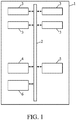
- the figure 1 very schematically shows an example of a computer cabinet according to one embodiment of the invention.
- a computer cabinet 1 contains an Ethernet bus 2 on which communicate on the one hand one or preferably several computer servers 3 and on the other hand liquid cooling modules 4, 5 and 6.
- the cooling modules 4 and 5 are in operation and cooling the computer servers 3, while the cooling module 6 is redundant, that is to say at rest but ready to take over and replace immediately, without intervention of an operator external to the computer cabinet 1, one of the other cooling modules 5 or 6, if it becomes faulty.
- the computer server (s) 3 are mounted on a frame of the computer cabinet 1 and are traversed by a secondary hydraulic cooling circuit conveying a fluid or a heat transfer liquid with a high calorific capacity much greater than that of the air, this fluid or coolant coming from the cooling modules in operation which are modules 4 and 5.
- the Ethernet network 2 allows communication between the controllers of each of the cooling modules 4 to 6.
- a failure at the level of this network 2 causes a degraded operating mode of this otherwise robust cooling system, in particular in the event of a failure.
- the redundant cooling module 6 immediately replacing the faulty cooling module, for example module 4.
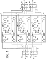
- the figure 2 schematically represents an example of the structure of primary and secondary hydraulic circuits in the liquid cooling modules of a computer cabinet according to one embodiment of the invention.
- a primary hydraulic circuit 7 supplies the three liquid cooling modules 4 to 6 with cold heat transfer liquid from a cold source 9 external to the liquid cooling modules 4 to 6.
- the liquid cooling modules 4 to 6 return to this cold source 9 heat transfer liquid heated by its passage through liquid cooling modules 4 to 6.
- the cold source 9 again cools this heat transfer liquid which starts another turn in the primary hydraulic circuit 7.
- the primary hydraulic circuit 7, coming from the cold source 9 is divided by a divider 71 into three branches of the primary hydraulic circuit 7 parallel to each other and passing respectively through the three liquid cooling modules 4 to 6.
- a coupler 72 groups together these three branches of primary hydraulic circuit 7 parallel to each other to reconstitute the primary hydraulic circuit 7 going to the cold source 9.
- These three liquid cooling modules 4 to 6 in turn supply the computer servers 3 with cooled heat transfer liquid.
- the computer servers 3 return to the liquid cooling modules 4 to 6 heat transfer liquid heated by the thermal energy dissipated by these computer servers 3 and evacuated by this heat transfer liquid.
- the liquid cooling modules 4 to 6 again cool this heat transfer liquid which starts another round in the secondary hydraulic circuit 8.
- the secondary hydraulic circuit 8, coming from the computer servers 3, is divided by a divider 81 into three circuit branches. secondary hydraulic 8 parallel to each other and respectively passing through the three liquid cooling modules 4 to 6.
- a coupler 82 groups these three branches of the secondary hydraulic circuit 8 parallel to each other to reconstitute the secondary hydraulic circuit 8 going to the computer servers 3.
- the primary hydraulic circuit 7 and the secondary hydraulic circuit 8 are not in fluidic contact, that is to say the coolants of these two hydraulic circuits do not mix with each other.
- the primary hydraulic circuit 7 and the secondary hydraulic circuit 8 are in thermal contact, that is to say that the coolants of these two hydraulic circuits exchange heat between them, when they pass through the exchangers 40, 50 and 60. liquid cooling modules 4 to 6.
- the cooling module 4 comprises an exchanger 40, a pump 41, a valve 42, a servo-control 43 of the PID type (proportional-integrator-diverter), an upstream pressure sensor 44, a pressure sensor. downstream pressure 45, an upstream secondary temperature sensor 46, a downstream secondary temperature sensor 47, an upstream primary temperature sensor 48, a downstream primary temperature sensor 49.
- PID type proportional-integrator-diverter
- the temperature of this cold heat transfer liquid is measured just after entering the liquid cooling module 4 by the upstream primary temperature sensor 48.
- the temperature of this heated coolant is measured just before it leaves the liquid cooling module 4 by the downstream primary temperature sensor 49.
- the pumping of the coolant in the primary hydraulic circuit 7 is pumped. performed by one or more pumps located outside the liquid cooling modules 4 to 6, and possibly p shared by the liquid cooling modules of several different computer cabinets.
- the temperatures measured by the primary temperature sensors 48 and 49 make it possible to check the correct operation of the primary hydraulic circuit 7.
- the temperature of this hot coolant is measured just after it enters the liquid cooling module 4 by the upstream secondary temperature sensor 46.
- the temperature of this heated coolant is measured just before it leaves the liquid cooling module 4 by the downstream secondary temperature sensor 47.
- the temperatures measured by the secondary temperature sensors 46 and 47 make it possible to check the correct operation of the secondary hydraulic circuit 8.
- the secondary circuit 8 ensures the circulation of the cooling liquid or heat transfer liquid, in the internal loop of the computer cabinet, at a temperature between 20 ° C and 45 ° C.
- the temperature sensor 47 is able to measure the temperature at the outlet of the secondary hydraulic circuit 8 of the cooling module 4, the flow rate of the coolant from the primary hydraulic circuit 7 being maintained at a flow rate chosen so that the temperature at the outlet of the secondary hydraulic circuit 8 is equal to a threshold temperature.
- the temperature at the inlet of the secondary cooling circuit 8 which passes through the computer servers 3, measured by the upstream secondary temperature sensor 46, is kept constant in order to optimize the cooling of the electronic components of their computing blades.
- the temperature regulation is independent for each of the liquid cooling modules 4 to 6, to ensure a constant temperature at the input of the computer servers regardless of their heat dissipation.
- the primary hydraulic circuit 7 relates to the circuits connected to the hydraulic network of the customer's infrastructure, the user of the IT cluster grouping together all the IT cabinets, for example in a computer room, and the secondary hydraulic circuit 8 concerns the hydraulic circuits connected to the control circuit. cooling of the computer cabinet.
- the cooling module 4 comprises a portion of the primary hydraulic circuit 7 comprising an outlet capable of being connected to the inlet of a customer primary hydraulic network and an inlet capable of being connected to the outlet of the customer primary hydraulic network 7.
- the cooling module 4 also comprises a portion of the secondary hydraulic circuit 8 comprising an output connected to the input of the secondary cooling circuit 8 of the computer cabinet and an input connected to the output of the secondary cooling circuit 8 of the cabinet. computer science.
- the input and output of the circuit primary hydraulic circuit 7 of each cooling module 4 to 6 are fitted with quick drip-free connectors making it possible to easily connect and disconnect the portion of the primary hydraulic circuit 7 of the cooling modules 4 to 6 to the rest of the primary hydraulic network 7 of the room IT cluster IT.
- the pressure of the heat transfer liquid in the branch of the secondary hydraulic circuit 8 is measured just upstream of the pump 41 by the upstream pressure sensor 44, as well as just downstream of the pump 41 by the downstream pressure sensor 45, in order to check the correct operation of the pump 41, and in order to be able to stop the pump 41 in the event of a malfunction of the latter.
- the pump 41 has sufficient power to circulate the secondary coolant in the internal loop at a pressure of about 3 bars at a flow rate of about 75 liters per minute of secondary coolant which is for example water. glycol.
- the pump 41 delivers a constant flow rate without pressure fluctuations generating vibrations thanks to the shape of the conduits of the pipes of the portion of the secondary hydraulic circuit 8 located in the cooling module 4.
- the pump 41 which is able to control the flow rate of the coolant in the secondary hydraulic circuit 8 is associated with control means capable of controlling this pump 41.
- the coolant in the secondary cooling circuit 8 preferably has a static pressure greater than or equal to 2 bars. Keeping this heat transfer liquid under pressure allows the pump 41 to be protected from any risk of cavitation, and the cooling system of the computer cabinet to operate even in the event of a leak.
- the inlet and outlet of the secondary hydraulic circuit 8 of each cooling module 4 to 6 are fitted with quick drip-free connectors allowing the portion of the secondary hydraulic circuit 8 to be easily connected and disconnected from the cooling modules 4 to 6 to the rest the secondary hydraulic circuit 8 of the computer cabinet cooling the computer servers 3.
- the exchanger 40 60 kW of heat are exchanged between the secondary hydraulic circuit 8 which gives them and the primary hydraulic circuit 7 which takes them, by means of a plate exchanger 40, of sufficient size to exchange this power. with similar or identical flow rates, or at least of the same order of magnitude, on both sides and an approach temperature of 4 ° C, this approach temperature corresponding to the difference between the external upstream temperature measured by the temperature sensor primary upstream 48 the internal downstream temperature measured by the downstream secondary temperature sensor 47.
- the heat exchanger 40 is able to cool the heat transfer fluid passing through the secondary hydraulic circuit 8 by dissipating heat through the primary hydraulic circuit 7.
- the servo-control 43 regulates the opening of the valve 42, and therefore the flow rate of the coolant from the primary hydraulic circuit 7 in the liquid cooling module 4, as a function of the temperature of the coolant from the secondary hydraulic circuit 8 at the outlet of the module. cooling liquid 4, measured by the downstream secondary temperature sensor 47.
- the liquid cooling module 4 also comprises means for controlling the correct operation of the module 4 and for detecting faults, as well as means for controlling the correct temperature regulation of the heat transfer fluid passing through the secondary hydraulic circuit 8, which are in particular the various temperature and pressure sensors associated with an electronic card shown on the figure 6 below.
- the cooling of the electronic control board of each liquid cooling module is carried out by the fan responsible for cooling the pump motor of this liquid cooling module.
- the cooling module 5 comprises an exchanger 50, a pump 51, a valve 52, a servo control 53 of the PID type (proportional-integrator-diverter), an upstream pressure sensor 54, a downstream pressure sensor 55, a temperature sensor upstream secondary 56, a sensor downstream secondary temperature sensor 57, an upstream primary temperature sensor 58, a downstream primary temperature sensor 59.
- the cooling module 5 is identical to the cooling module 4.
- the cooling module 5 operates identically to that of the cooling module 4.
- the cooling module 6 comprises an exchanger 60, a pump 61, a valve 62, a servo control 63 of the PID type (proportional-integrator-diverter), an upstream pressure sensor 64, a downstream pressure sensor 65, a temperature sensor upstream secondary 66, a downstream secondary temperature sensor 67, an upstream primary temperature sensor 68, a downstream primary temperature sensor 69.
- the cooling module 6 is identical to the cooling module 4.
- the cooling module 6 operates identically to that of the cooling module 4.
- the three cooling modules 4 to 6 can operate in basic redundancy, that is to say with three active modules with change to two active modules when one of these modules fails or is removed.
- the operating mode in special conditions, for example when the cooling system is initialized, is basic redundancy operation.
- the three cooling modules 4 to 6 can operate in optimized redundancy, i.e. with two active modules 4 and 5 and one module 6 in reserve, ready to start if one of the two active modules 4 or 5 is stopped at following a failure or removal of this module.
- the normal or cruising mode of operation is the optimized redundancy operation.
- Each of the n modules of liquid cooling is removable to allow maintenance without stopping the cooling of the computer servers 3 present in the computer cabinet.
- Regulation and fault detection is carried out by monitoring temperature sensors 46 to 49, 56 to 59 or 66 to 69 and pressure sensors 44 and 45, or 54 and 55 or 65 and 66, using an electronic card specific to each cooling module 4, 5 or 6.
- the dialogue between the cards of the three liquid cooling modules 4 to 6 is carried out by means of the TCP protocol ("Transmission Control Protocol / Internet Protocol” in English) or the UDP protocol ("User Datagram Protocol” in English language). ).
- the three liquid cooling modules 4 to 6 also send messages to the SNMP standard ("Simple Network Management Protocol" in English) to a general system for monitoring the cabinet and managing the computer room comprising several cabinets. computer science. Between the three liquid cooling modules 4 to 6, there is no master / slave system, because the loss of the master controller would then lead to the loss of the cooling system as a whole, which the invention seeks to avoid by making it more robust against breakdowns.
- the standby liquid cooling module change is programmed to check its availability as a redundant liquid cooling module, i.e. the backup liquid cooling module, so that it is operational in an emergency. .
- a sufficient number of liquid cooling modules are continuously active at the same time, to provide the sufficient quantity of flow rate of the coolant liquid to the computer servers 3; here the liquid cooling modules 4 and 5 operate while the liquid cooling module 6 is at rest, kept in reserve.
- Cooling modules 4 to 6 are used to supply the heat transfer liquid at a maximum constant temperature for each of the blades calculation included in the computer servers 3 mounted on the frame of the computer cabinet.
- liquid cooling modules 4 and 5 Two, or else n strictly greater than two in the case of a generalization, of the liquid cooling modules 4 and 5 are active, while the other liquid cooling module 6 is active or inactive, depending on the possible redundancy mode chosen. which can be basic redundancy or even preferentially optimized redundancy.
- the controller of the inactive liquid cooling module 6 is informed by the network 2 and starts its liquid cooling module 6, so that the computer cabinet is always cooled by at least two liquid cooling modules.
- the computer cabinet can continue to operate normally; however, in the unlikely event of a second failure before repair of the first failure, consisting essentially of the standard exchange of the faulty liquid cooling module, the cooling will of course deteriorate.
- Liquid cooling modules 4 to 6 can be removed in the event of maintenance without stopping the cooling of computer servers 3.
- Liquid cooling modules 4 to 6 are used to regulate the heat transfer liquid in temperature, to ensure a constant temperature at the input of computer servers 3 regardless of their heat dissipation.
- cooling modules 4 to 6 are able to detect failures by monitoring pressure and temperature sensors using control means specific to each liquid cooling module.
- the hydraulic components of the cooling module are optimized, on the one hand, in terms of pressure drop consumption, in order to minimize the hydraulic energy that the pump 41 must supply and thus optimize its size and its electrical consumption, on the other hand. , in terms of bulk in order to improve the compactness of the liquid cooling module.
- the cooling system according to a preferred embodiment of the invention makes it possible to dissipate 120 kW for two active liquid cooling modules 4 and 5.
- the liquid cooling modules 4 to 6 are identical to each other to be interchangeable and to be replaced by a spare module stored on site in the computer room or nearby. A failed liquid cooling module should be repaired at another site, it is strongly recommended not to open the liquid cooling module at the computer room site. Replacement liquid cooling modules are available on site.
- the only maintenance operation authorized on site is the removal of the faulty liquid cooling module and its replacement by a spare liquid cooling module in a few minutes, without interruption of service at the level of the computer servers 3 of the computer cabinet.
- these three cooling modules 4 to 6 are placed in a lower part of the computer cabinet, the computer servers 3 being placed in an upper part of this same computer cabinet.
- the lower part is located under the upper part, when the computer cabinet is installed (upright) in operation.
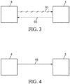
- the figures 3 and 4 schematically represent an example of communication between different liquid cooling modules of the same computer cabinet during an initialization phase according to one embodiment of the invention.
- a first liquid cooling module 4 broadcasts data representative of its identity by a broadcast 91 by a UDP broadcast protocol (“Broadcast UDP” in English).
- the message 91 includes the identifier of the first cooling module, an identifier of its group of cooling modules included in its cooling cabinet, and its Internet address.
- a second cooling module 5 receiving this broadcast 91 sends back to the first liquid cooling module 4 a targeted message 92 which contains on the one hand its own data representative of its own identity and on the other hand an acknowledgment of receipt of the broadcast 91.
- the message 92 includes an acknowledgment of receipt of the message 91, the identifier of the second cooling module, an identifier of its group of cooling modules included in its cooling cabinet (which is therefore the same as that of the first cooling module) , its Internet address (the Internet address of the second cooling module).
- This is a first phase of identification which is carried out prior to the phase of communication and data exchange described on the figure 4 below.
- This first phase of identification is carried out in broadcast mode by means of a TCP protocol or a UDP protocol.
- the table of Internet addresses of the cooling modules of this group can be built locally at each of these cooling modules, then allowing the method of exchanging information to update their state in operation to unfold.
- This broadcast is performed by each of the cooling modules several times over a period of 2 minutes, since it is an asynchronous communication, to allow the other liquid cooling modules to receive this broadcast.
- Each of the cooling modules then acts both as a client-type data transmitter and as a server-type data receiver.
- the first liquid cooling module 4 sends, to the other liquid cooling modules 5 and 6 of the common computer cabinet, periodically, a targeted message 93 containing on the one hand a reminder of its data representative of its identity and an update of certain parameters of its operation.
- Each of the other liquid cooling modules 5 and 6 does the same thing, that is to say sends, to the other liquid cooling modules of the common computer cabinet, periodically, the same targeted message 93 containing d '' on the one hand, a reminder of its data representative of its identity and an update of certain parameters of its operation.
- the period used here is one second.
- the structure of the data exchanged is as follows and can include in order: the identifier of their common group, the identifier of the cooling module, one or more status variables, one or more cooling parameters, one or more cooling variables.
- the cooling module modifies its state variables according to its environment.
- the status of the computer cabinet is constructed by the general control and supervision system of all the computer cabinets, that is to say by the general control and supervision system of the computer cluster. For this, this general control and supervision system can interrogate each cooling module, for example using IPMI commands (“Intelligent Platform Management Interface”) periodically, for example every second. Alternatively, a script outside the cabinet computer can periodically interrogate, for example every second, the various cooling modules.
- IPMI commands Intelligent Platform Management Interface
- Each of the liquid cooling modules 4 to 6 operates independently and regulates its operation without any of the liquid cooling modules 4 to 6 playing the role of a master controlling the other modules as slaves, thanks to the communication protocol collaborative between the liquid cooling modules 4 to 6.
- Each of the liquid cooling modules 4 to 6 can start by itself.
- Each of the liquid cooling modules 4 to 6 knows the topology of its computer cabinet and therefore of the group of associated liquid cooling modules, as well as its group identifier, as well as its position within this group, all this information being communicated to it. by another computer network when the process for starting the computer cabinet is started.
- the cooling module knows its group identifier and its position in this group independently of its Internet address which is communicated to it by DHCP (“Dynamic Host Configuration Protocol”).
- DHCP Dynamic Host Configuration Protocol
- the figure 5 schematically represents an exemplary operating diagram of a liquid cooling module communicating with the other liquid cooling modules of the same computer cabinet according to a collaborative communication protocol according to one embodiment of the invention.
- the cooling modules communicate with each other by a collaborative protocol, without master or slave, they are required to make their decisions most often unanimously, sometimes by majority.
- the cooling module can take different states or statuses, among which an off state 10, a start state 11, a drain state 12, a test state 13, a self-test state 14, a preheating state 15, an autonomous state 16, a state regulated 17, a failed status 18, an excluded status 19, a redundant status 20.
- the cooling module is electrically de-energized.
- the cooling module In the start-up state 11, the cooling module is energized and performs its start-up.
- the cooling module performs maintenance making it possible in particular to empty the water from the portion of the primary circuit of the cooling module.
- the cooling module performs a test to verify its correct operation. After the verification test is completed at the factory of the cooling module manufacturer, this cooling module will be put into the excluded status 19, with default values of the cooling parameters. A new cooling module or a reserve cooling module will in principle be put in the excluded status 19. After the manual introduction of a cooling module in the computer cabinet, this cooling module will start in the excluded status 19 and will stay there until further notice. Then, the external operator will then control the cooling parameters of this cooling module with those of the other cooling modules present in the common computer cabinet because they belong to the same group of cooling modules. It is only after this control phase that this cooling module can be included in this group of cooling modules. While this cooling module remains in the excluded status 19, it is the value of its own identifier which will remain assigned to its redundant cooling module parameter.
- the cooling module itself performs a test to verify its correct operation.
- the cooling module performs preheating.
- the cooling module cools correctly but it is not yet synchronized with the other modules cooling. If at least one of the cooling modules succeeds in passing to the stand-alone status 16, then the computer cabinet is powered up as well as all the computer servers it contains.
- the cooling module cools properly and it is already synchronized with the other cooling modules.
- the cooling module In the failed status 18, the cooling module no longer works properly and no longer cools properly, it has failed. In faulty status 18, the cooling module will switch off its pump electrically, in particular in two cases, when the risk of condensation becomes too high, or when the pressure in the secondary circuit becomes too low. Before going into faulty status 18, the cooling module will send an alert which will be received by the general manager supervising the computer cabinets of the computer cluster. When all the cooling modules are in the faulty status 18, the general manager supervising the computer cabinet can therefore see that they are all in the faulty status 18, that all the pumps are stopped, that the cooling is stopped, that it is therefore necessary to switch off the entire computer cabinet, that is to say all the computer servers it contains.
- cooling module As long as a cooling module remains in the faulty status 18 and has not passed into the excluded status 19, it can be reset by an operator outside the computer cabinet. If, during this reset, the fault 31 has not returned, this cooling module will go first to the autonomous status 16 and then possibly to the regulated status 17. If, during this reset, the fault 31 returns, this cooling module will switch, on receipt of an exclusion command 36 from an external operator, to the excluded status 19.
- the cooling module is explicitly excluded from the group of cooling modules. He will need a explicit inclusion command to be able to be reintegrated into the group of cooling modules. Without this explicit inclusion command, even a power-on 21 or restart 23 command will not result in its reintegration into its group of cooling modules.
- the restart command 23 can also be performed from virtually any other state or state except from the off state 10.
- the cooling module In the redundant status 20, the cooling module is in redundancy, that is to say it is at rest, and it is ready to switch to a stand-alone status 16 to replace another cooling module of their own. common group, to cool in its place, if this other cooling module has either gone into a faulty status 18 or has been put into an excluded status 19.
- the cooling module changes from one state or status to another, either through a command from an external operator, or through an operation that it performs itself when the corresponding condition is met. fulfilled.
- a power supply command 21 an emptying command 22, a restart command 23, an autotest start command 24, an autotest output command 25, an autotest start command.
- test 26 a cooling power supply control 27, an exclusion control after failure to start 28, an inclusion control 29, a preheat terminate operation 30, a failure 31, a preheat failure 32, an operation for noticing data consistency 33, an operation for noting data inconsistency 34, an operation to switch to redundancy 35, an exclusion command 36.
- the power supply control 21 energizes the cooling module and initiates the start-up of this module. cooling.
- the power supply control 21 changes the cooling module from an off state 10 to a start state 11.
- the drain control 22 gives the order to carry out maintenance making it possible in particular to empty the water from the portion of the primary circuit of the cooling module.
- the drain control 22 changes the cooling module from a start state 11 to a drain state 12.
- the restart command 23 gives the order to the cooling module to perform a restart.
- the restart command 23 changes the cooling module from a drain state 12 to a start state 11, or else from a test state 13 to a start state 11.
- the start self-test command 24 instructs the cooling module to start a self-test.
- the self-test start command 24 changes the cooling module from a test state 13 to a self-test state 14.
- the self-test output command 25 instructs the cooling module to stop the self-test.
- the self-test output command 25 changes the cooling module from a self-test state 14 to a test state 13.
- the test start command 26 instructs the cooling module to start a test.
- the test start command 26 changes the cooling module from a test state 13 to a start state 11.
- the cooling power control 27 instructs the cooling module to begin preheating.
- the cooling power control 27 changes the cooling module from a start state 11 to a preheat state 15.
- the exclude after failed start command 28 excludes the cooling module from its group of cooling modules after a failed start.
- the exclude after failure command start-up 28 changes the cooling module from a start-up state 11 to an excluded state 19.
- the include control 29 includes or re-includes the cooling module in its group of cooling modules.
- the inclusion command 29 changes the cooling module from an excluded status 19 to a start state 11.
- the inclusion command 29 is sent to one of the cooling modules, then the inclusion process begins when this cooling module receives this inclusion command 29, preferably in the form of an IPMI command.
- This cooling module assigns the value of its own identifier to its redundant cooling module parameter, which in fact should already be the case.
- This cooling module passes to the start state 11, the cooling parameters having normally been initialized directly by the operator beforehand during the previous exclusion process. If a cooling power supply command 27 is received by this cooling module, the latter will go to the autonomous status 16 first, and to the regulated status 17 then if an operation to ascertain the consistency of the data 33 is carried out. Then, if the stability indicator also becomes positive, then this cooling module will pass to the redundant status 20 by a switching operation to redundancy 35.
- the preheating termination operation 30 stops the preheating of the cooling module.
- the preheat termination operation 30 changes the cooling module from a preheat state 15 to a stand-alone state 16.
- Failure 31 is a failure of the cooling module. Failure 31 changes the cooling module to a failed status 18 from stand-alone status 16, or from regulated status 17, or from redundant status 20. When failure 31 occurs for one of the cooling modules, then this cooling module assigns the value of its own identifier to its parameter cooling module redundant, sends a request to the other cooling modules asking them to set their redundant cooling module parameter to the same value as it. Then, the redundant cooling module leaves the redundant status 20 to go to the regulated status 17 or rather quickly to the autonomous status 16, because the stability indicator will become negative since one of the cooling modules, the one which has just passed. in defaulted status 18, is no longer in regulated status 17.
- the preheating 32 failure is a failure of the cooling module occurring during its preheating. Failure of the preheat 32 causes the cooling module to enter a failed state 18 from a preheat state 15.
- the operation of noting the consistency of the data 33 makes positive or leaves positive the indicators of consistency of the cooling modules.
- the data consistency finding operation 33 changes the cooling module from an autonomous status 16 to a regulated status 17.
- the operation of noticing data inconsistency 34 renders negative or leaves negative at least one of the indicators of consistency of the cooling modules.
- the data inconsistency finding operation 34 changes the cooling module to an autonomous status 16 from a regulated status 17, or else from an autonomous status 20.
- one of the cooling modules active switches to faulty status 18, it stops its pump, and the cooling module which was in redundant status 20 starts its pump by itself to switch to autonomous status 16.
- the switch-over to redundancy operation puts a single cooling module at rest with the ability to resume cooling immediately in the event of an emergency, in particular to replace another cooling module that has failed.
- the failover operation to redundancy 35 changes the cooling module from a regulated status 17 to a redundant status 20.
- the exclusion command 36 excludes the cooling module from its group of cooling modules.
- the exclusion command 36 changes the cooling module to an excluded status 19 from an autonomous status 16, or else from a regulated status 17, or else from a faulty status 18, or else from a redundant status 20.
- the exclusion process begins when this cooling module receives this exclusion command 36, preferably in the form of an IPMI command.
- This cooling module assigns the value of its own identifier to its redundant cooling module parameter, sends a request to the other cooling modules asking them to set their redundant cooling module parameter to the same value as it. Then, the redundant cooling module leaves the redundant status 20 to go either to the autonomous status 16 or to the regulated status 17.
- the exclusion command 36 is, for the cooling module to which it is sent, the first step of the process tending to remove a cooling module in faulty status 18, out of the computer cabinet, in order to perform maintenance on this cooling module. cooling.
- the cooling modules communicate with each other periodically, by means of a collaborative protocol, in order to exchange a set of data between them, in order to be able to check first whether this set of data is coherent, which will result in a consistency indicator becoming positive, and then if this data set remains consistent in a stable manner over time, which results in a stability indicator becoming positive.
- each cooling module checks several things, namely that it checks a possible loss of communication with one or other of the other cooling modules, that it also checks the consistency of the data exchanged, as well as the stability over time of the coherence of these exchanged data. These checks can be carried out while this cooling module is either in stand-alone status 16, or in regulated status 17, or in redundant status 20.
- the loss of communication check between cooling modules consists, for each of the cooling modules, of verifying that there have been no communication loss problems on the Ethernet network on which these cooling modules communicate with each other.
- one of the cooling modules may be missing, that is to say no longer transmitting on the Ethernet network bus, in which case its data is no longer taken into account in all the data of the group and are no longer retained to perform the data consistency check operation 33.
- two of the three cooling modules may be missing, that is to say no longer send on the Ethernet network bus, in which case only the data of the last cooling module still capable of communicating and therefore sending on the Ethernet buses are taken into account in all the data of the group and are retained to perform the operation of noting the consistency of the data 33.
- one of the cooling modules can be switched to the faulty status 18 or to the excluded status 19, in which case its data are no longer taken into account in all the group's data and are no longer retained to perform the operation. data consistency finding operation 33.
- the consistency check of all the data exchanged may relate to all or part of the data exchanged. Periodically, for example every second, a process will compare if the cooling parameters are equal between all the cooling modules, and if this equality is maintained for at least 10 seconds.
- the cooling parameters include, on the one hand, the redundant cooling module parameter, the value of which is that of the identifier of the cooling module which is supposed to go into redundancy, that is to say at rest, when the conditions will be favorable, that is to say when the switching operation to redundancy 35 will take place, and on the other hand the cooling regulation parameter, the value of which is that of the target temperature for regulating the coolant circulating in the secondary hydraulic circuit at the exchanger outlet.
- the general monitoring system of the computer room or an external operator can initialize the cooling parameters of each computer cabinet by sending IPMI commands to all the cooling modules of the corresponding computer cabinet. Normally, these commands will be sent and received by all of the cooling modules at almost the same time. As an additional security measure, a safety margin can be taken and the time slot for making these sendings can be extended to 10 seconds.
- each cooling module After each cooling module has received the IPMI commands, it changes its cooling parameters and goes into regulated status 17.
- the other cooling modules in turn have a time slot of 10 seconds also to receive these parameter values from. cooling, update their cooling parameters from these received values, and send their own cooling parameters back to other cooling modules. If this data exchange is not carried out within the allotted time, then each cooling module having observed the failure will go into the autonomous status 16, since the consistency indicator will be negative.
- the consistency indicator remains or becomes positive when the three following conditions are realized simultaneously.
- the first condition is fulfilled when the set of data exchanged between cooling modules has been updated for at most 2 seconds, i.e. at most one update sent has been missed by one either of the cooling modules.
- the second condition is met when the redundant cooling module parameters are equal to each other for all the cooling modules in the group, and have been for at least 10 seconds.
- the third condition is fulfilled when the cooling regulation parameters are equal to each other for all the cooling modules of the group, and this for at least 10 seconds.
- the consistency indicator remains or becomes negative when at least one of the three preceding conditions is not or is no longer fulfilled.
- the cooling module can go from the autonomous status 16 to the regulated status 17.
- the consistency indicator is negative, the cooling module which is in the autonomous status 16 remains there. If a negative consistency indicator persists, corrective action is taken, for example by the external operator, to analyze and correct the one or more of the cooling parameters which are responsible for the persistence of a cooling indicator. negative consistency.
- the stability check of all the data exchanged can relate to all or part of the data exchanged.
- the stability check covers the same data as that which is the subject of the consistency check. Periodically, for example every second, a process will check that the consistency indicator remains positive for a certain time during which the cooling modules remain synchronized with each other and none of them have received an alarm from cooling malfunction. When the stability indicator remains or becomes positive, the cooling module which is supposed to go to rest, that is to say to become redundant, will actually become so or remain so if it is already there.
- the stability indicator remains or becomes positive when the following three conditions are met simultaneously.
- the first condition is met when all of the consistency indicators at the cooling module level remain positive for at least 3 minutes.
- the second condition is met when no cooling malfunction alarm has been received by a cooling module. Such a cooling malfunction alarm can for example be received because of a pump or exchanger that has become defective.
- the third condition is fulfilled when at least two of the three (or n of the n + 1) cooling modules of the group are in regulated status 17, the third (or last) cooling module of the group being either in the regulated status 17, or in redundant status 20.
- the stability indicator remains or becomes negative when at least one of the three preceding conditions is not or is no longer fulfilled.
- the stability indicator is positive, and one of the cooling modules points its cooling module parameter to its own identifier, then this cooling module can go from regulated status 17 to redundant status 20, and only in this case.
- the stability indicator is negative, no cooling module can switch to redundant status 20, but must instead remain in regulated status 17.
- the figure 6 shows the internal arrangement of an example of a compact liquid cooling module according to one embodiment of the invention.
- the cooling module dissipates about 60kW.
- the cooling module comprises an outer casing 100 integrating several components.
- the heat transfer fluid is a heat transfer liquid, for example glycol water.
- a primary hydraulic circuit 7, containing a coolant liquid crosses, without mixture of coolant liquid, but with heat exchange between the coolant liquids, a secondary hydraulic circuit 8, containing a coolant liquid, inside the outer casing 100 of the liquid cooling module, inside a heat exchanger 102.
- the outer casing 100 comprises two long side walls 131 and 132 opposite to each other, two short side walls 133 and 134 opposite to each other, a bottom 135 opposite to a cover 136 which is not. visible on the figure 6 because it has been removed to show the interior of the outer casing 100.
- the terms “long” and “short” only mean that the long sidewalls 131 and 132 are longer than the short sidewalls 133 and 134.
- the terms “long” and “short” mean only that the long side walls 131 and 132 are longer than the short side walls 133 and 134.
- the general shape of the outer housing 100 is parallelepiped.
- the long side walls 131 and 132 are of substantially the same length between them.
- the short side walls 133 and 134 are of substantially the same length between them.
- the outer case 100 has a length L of 76cm, a width 1 of 59.5cm and a thickness e of 15cm.
- a pump 101 a heat exchanger 102, an electronic card 103, a valve 104, an inlet grille 105, two outlet grids 106 and 107, an anti-valve. return 108, a clear central longitudinal space 109, a leak detector 110, pressure sensors 111, a power supply relay 112, temperature sensors 113, an air guide 114, a fan 117, pipes 121 to 123 in the secondary hydraulic circuit 8, pipes 124 and 125 in the primary hydraulic circuit 7.
- the terms pipes and pipes are used interchangeably.
- the pump 101 is oriented in the direction of the length of the outer casing 100 and located along the long side wall 132, it is placed right against this long side wall 132.
- the axis of the pump 101 is aligned with the upstream pipe. 121 to have a regular supply of the pump 101.
- This upstream pipe 121 is a flexible pipe for connecting the pump 101, which allows it to compensate for alignment errors and allows the dismantling of the pump 101 for maintenance.
- the heat exchanger 102 is oriented in the direction of the length of the outer casing 100 and located along the other long side wall 131, it is arranged very close to this other long side wall 131 without any other element between them. 'a pipeline.
- the heat exchanger 102 is an exchanger 102 lying on the side to minimize bulk, a plate heat exchanger 102 with cross flow, made of copper brazed stainless steel, in order to have better heat exchange performance.
- An external insulation layer surrounds on the one hand the exchanger 102 and on the other hand the pipe or pipes 124 and 125 of a portion of the primary hydraulic circuit 7 located in the cooling module, so as to avoid condensation on their outer walls, even when the temperature of these outer walls is lower than the dew point temperature of the cooling module.
- This insulation, on the exchanger 102 and on the pipes 124 and 125 of the primary circuit 7, thus prevents a condensation monitoring system liable to trigger a cooling malfunction alarm without a valid reason.
- the pipes 124 and 125 have elbows at the outlet and at the inlet of the exchanger 102 to minimize the bulk.
- the electronic card 103 itself comprises two parts which are on the one hand a logic part 115 and on the other hand a connection part 116.
- This electronic control card 103 is arranged in the longitudinal extension of this central longitudinal space 109 cleared of so as to be directly licked by the flow of air passing through it.
- the two parts 115 and 116 which can be separated from each other, of this electronic card 103, are on the one hand a logic part 115 which can be removed without dismantling the rest of the cooling module and on the other hand a connection part 116 fixed on the bottom 135 of the module. cooling without being separately removable.
- To this connection part 116 are connected all the connections of the components of the liquid cooling module leading to this electronic card 103.
- This electronic card 103 does not include a protective cover and is directly in contact with all the air flow. from the central longitudinal space cleared 109. This electronic card 103 dissipates a heat output of about 10W. This electronic card 103 is a centralized electronic regulation card, cooled by the air flow created by the fan 117 of the pump 101.
- the valve 104 is located on a portion of the primary hydraulic circuit 7 located in the cooling module, the function of which is to indirectly regulate the temperature of the coolant in the secondary hydraulic circuit 8 at the outlet of the heat exchanger 102, this valve 104 being advantageously a proportional ball valve 104.
- This proportional ball valve 104 includes a device for adjusting the passage section favoring the linearity of the flow response as a function of the opening angle, with a servomotor mounted lying down to minimize the bulk, with a control electric allowing precise opening and a more precise reading of this opening than with a proportional solenoid valve.
- the inlet ventilation grille 105 is located in the short side wall 133.
- the two outlet ventilation grilles 106 and 107 are respectively located in the short side wall 134.
- the grille 106 is a first outlet ventilation grille 106. air out of the cooling module and is located just downstream of the electronic card 103.
- the grid 107 is a second ventilation grid 107 for air outlet from the cooling module and is located just downstream of the valve 104. The sum of the areas of the air outlet ventilation grilles 106 and 107 is equal to the area of the air inlet ventilation grill 105.
- the non-return valve 108 is located on the section of the secondary hydraulic circuit 8 located between the outlet of the pump 101 and the inlet of the heat exchanger 102.
- the non-return valve 108 is located near the exchanger 102 to create a removable block, which is interesting to avoid the risk that the flow from the other cooling modules enters it when its pump 101 is stopped. .
- the central longitudinal space cleared 109 is arranged between the pump 101 and the exchanger 102 so as to facilitate an air flow there from a grille 105 of a short side wall 133 towards the two grids 106 and 107 of the another short side wall 134, this air flow being driven by the fan 117 of the pump 101.
- a portion of the secondary hydraulic circuit 8, for the circulation of a heat transfer liquid, located in the liquid cooling module, does not include any bypass which would allow the pump 101 to operate in a closed circuit and which would be liable to encumber this longitudinal space.
- clear central 109 This clear central longitudinal space 109 between the components of the cooling module is sufficient to promote the passage of cooling air between on the one hand the upstream grid 105 and on the other hand the downstream grids 106 and 107, so that both the electronic card 103 and the valve 104 are well cooled.
- the leak detector 110 is located in the bottom 135 of the outer casing 100. This leak detector 110 is placed near the evacuation pipe 125, the bottom 135 of the outer casing 100 is sealed and makes it possible to accommodate a significant quantity of liquid. in the event of a leak. The leak is only detected if it is relatively large, small leaks are deliberately not taken into account, as they are not very annoying.
- the pressure sensors 111 are located respectively at the inlet and at the outlet of pump 101 in order to check the operation of the latter.
- the power supply relay 112 for the pump 101 is housed in a sealed box which accommodates high supply voltages for the pump 101, in alternating current.
- the temperature sensors 113 ensure the monitoring and regulation of the circulation of heat transfer liquid in the primary 7 and secondary 8 circuits: there is one at the level of each pipe 121, 122, 124, 125 near their crossing of the wall short lateral 134.
- the air guide 114 channels the air between on the one hand the ventilation grid 105 for the air inlet in the cooling module and on the other hand the inlet of the pump 101.
- the pump 101 being placed near of the grille 105 located on the front face of the exterior housing 100, its fan 117 sucks in cool air coming from the outside through this grille 105 with an air guide 114 to avoid re-sucking hot air which had already passed through the cooling module.
- the air cooling fan 117 of the pump 101 is coupled to the electric shaft of the motor of the pump 101.
- the elbows of the various pipes 121 to 125 are elbows with a large radius of curvature to minimize the pressure drop and not to disturb the flow of coolant in these same pipes 121 to 125.
- the crossings of the short side wall 134 of the housing exterior 100 are compact and do not have a significant change in section in order to minimize the pressure drop.
- the primary 7 and secondary 8 circuits include flexible connectors which are well aligned with the rigid pipes 121 to 125 to minimize changes in passage section and disturbances in the flow of coolant liquid. Likewise, pressure fluctuations are reduced as well as vibrations generated in the cooling module and throughout the rest of the computer cabinet. Furthermore, erosion is also minimized by the regularity of the flow of heat transfer liquid in the rigid pipes 121 to 125.
Landscapes
- Engineering & Computer Science (AREA)
- Microelectronics & Electronic Packaging (AREA)
- Physics & Mathematics (AREA)
- General Engineering & Computer Science (AREA)
- Thermal Sciences (AREA)
- Computer Hardware Design (AREA)
- Theoretical Computer Science (AREA)
- General Physics & Mathematics (AREA)
- Human Computer Interaction (AREA)
- Manufacturing & Machinery (AREA)
- Automation & Control Theory (AREA)
- Cooling Or The Like Of Electrical Apparatus (AREA)
- Hardware Redundancy (AREA)
Claims (16)
- Verfahren zur Kommunikation zwischen mehreren Flüssigkühlmodulen (4, 5, 6) eines Kühlsystems eines oder mehrerer Netzwerkserver (3), dadurch gekennzeichnet, dass:die Kühlmodule (4, 5, 6) so miteinander kommunizieren, dass sie in N+1-Redundanz mit N größer gleich 2 arbeiten, um einen Standardaustausch eines dieser Kühlmodule (4, 5, 6) durchführen zu können, ohne die Kühlung zu stoppen und ohne den Betrieb des/der Server(s) (3) zu stoppen,
 diese Kommunikation durch ein kollaboratives Protokoll ohne Master/Slave bereitgestellt wird,das redundante Kühlmodul (6) vor dem Umschalten (35) von einem aktiven Modus (16, 17), in dem es kühlt, in einen Backup-Modus (20), in dem es nicht mehr kühlt, einerseits überprüft (33), dass ein Satz von Daten zwischen all diesen Kühlmodulen (4, 5, 6) kohärent ist, und andererseits, dass diese Kohärenz über eine vorbestimmte Zeitdauer aufrechterhalten wird.
 - Verfahren zur Kommunikation zwischen mehreren Flüssigkühlmodulen (4, 5, 6) nach Anspruch 1, dadurch gekennzeichnet, dass:die Kühlmodule (4, 5, 6) über ein Ethernet-Netzwerk (2) miteinander kommunizieren,wobei dieses Ethernet-Netzwerk (2) auch das Netzwerk sein kann, über das externe Befehle an die Netzwerkserver (3) übertragen werden und das allgemeine Netzwerk eines Netzwerk-Clusters ist, das mehrere Netzwerkschränke (1) zusammenfasst, die an der Ausführung einer gemeinsamen Datenverarbeitungsaufgabe teilnehmen können.
- Verfahren zur Kommunikation zwischen mehreren Flüssigkühlmodulen (4, 5, 6) nach einem der vorhergehenden Ansprüche, dadurch gekennzeichnet, dass:während einer Initialisierungsphase jedes Kühlmodul (4, 5, 6) wenigstens seine Kennung und eine Kennung des Netzwerkschranks (1), in dem es sich befindet, sendet (91),während dieser Initialisierungsphase jedes Kühlmodul (4, 5, 6), nachdem es die Kennung eines anderen Kühlmoduls (4, 5, 6), welches sich im gleichen Netzwerkschrank (1) befindet, empfangen hat, an dieses eine Zielnachricht zurück sendet (92), die den Empfang bestätigt und die eigene Kennung und eine Kennung ihres gemeinsamen Netzwerkschranks (1) mitteilt, um eine Informationsaustauschgruppe zu bilden, die von den anderen, zu anderen Informationsaustauschgruppen gehörenden Kühlmodulen isoliert ist,und dass nach Abschluss dieser Initialisierungsphase jedes Kühlmodul (4, 5, 6) seine Daten periodisch mit einer Aktualisierungszeitdauer an die anderen Kühlmodule (4, 5, 6) der von ihm identifizierten Informationsaustauschgruppe sendet (93).
- Verfahren zur Kommunikation zwischen mehreren Flüssigkühlmodulen (4, 5, 6) nach einem der vorhergehenden Ansprüche, dadurch gekennzeichnet, dass:
jedes der Kühlmodule (4, 5, 6) wenigstens die folgenden zwei Zustände aufweisen kann:∘ im aktiven Modus einen autonomen Zustand (16), in dem das Kühlmodul (4, 5, 6) korrekt kühlt, es ihm aber nicht gelingt, sich mit allen anderen Kühlmodulen (4, 5, 6) zu synchronisieren,∘ im aktiven Modus einen geregelten Zustand (17), in dem das Kühlmodul (4, 5, 6) korrekt kühlt und es ihm gelingt, sich mit allen anderen Kühlmodulen (4, 5, 6) zu synchronisieren. - Verfahren zur Kommunikation zwischen mehreren Flüssigkühlmodulen (4, 5, 6) nach einem der vorhergehenden Ansprüche, dadurch gekennzeichnet, dass:jedes der Kühlmodule (4, 5, 6) wenigstens die folgenden zwei Zustände aufweisen kann:∘ im Falle eines Fehlers einen Fehlerzustand (18), in dem das Kühlmodul (4, 5, 6) nicht mehr korrekt kühlt (31), obwohl es weiterhin korrekt kühlen sollte,∘ im Backup-Modus einen redundanten Zustand (20), in dem das Kühlmodul (4, 5, 6) inaktiv ist, aber bereit bleibt, ein anderes, defekt werdendes Kühlmodul (4, 5, 6) sofort zu ersetzen,wenn ein Kühlmodul (4, 5, 6) in den Fehlerzustand (18) übergeht (31), stoppt es selbst seine Wärmeträgerflüssigkeits-Umwälzpumpe (41, 51, 61, 101) im sekundären Hydraulikkreis (8).
- Verfahren zur Kommunikation zwischen mehreren Flüssigkühlmodulen (4, 5, 6) nach einem der Ansprüche 4 bis 5, dadurch gekennzeichnet, dass:
wenn es zunächst einem der Kühlmodule (4, 5, 6) gelingt, in den autonomen Zustand (16) überzugehen (30), der Netzwerkschrank (1) eingeschaltet wird und die darin enthaltenen Netzwerkserver (3) ebenfalls eingeschaltet werden. - Verfahren zur Kommunikation zwischen mehreren Flüssigkühlmodulen (4, 5, 6) nach einem der Ansprüche 4 bis 6, dadurch gekennzeichnet, dass:
die Kühlmodule (4, 5, 6) jeweils einen Parametersatz aufweisen, umfassend:∘ einen Parameter für ein redundantes Kühlmodul, der auf die Kennung des Kühlmoduls verweist, das bei der nächsten günstigen Gelegenheit in den redundanten Zustand umschalten kann,∘ wenigstens einen Kühlungsregelungsparameter, der auf einen Sollwert eines Kühlungsregelungsparameters verweist, der die Zieltemperatur der Wärmeträgerflüssigkeit im sekundären Hydraulikkreislauf (8) am Ausgang des Wärmetauschers (40, 50, 60, 102) ist. - Verfahren zur Kommunikation zwischen mehreren Flüssigkühlmodulen (4, 5, 6) nach Anspruch 7, dadurch gekennzeichnet, dass:
jedes Kühlmodul (4, 5, 6) einen Kohärenzindikator aufweist:∘ der positiv ist, wenn die folgenden drei Bedingungen gleichzeitig erfüllt sind:▪ das Kühlmodul (4, 5, 6) hat von allen anderen Kühlmodulen (4, 5, 6) wenigstens die Werte des Parameters des redundanten Kühlmoduls und des Parameters der Kühlungssteuerung erhalten, die seit weniger als einer ersten vorbestimmten Zeitdauer aktualisiert wurden,▪ alle empfangenen Werte des Parameters des redundanten Kühlmoduls sind über mehr als eine zweite vorbestimmte Zeitdauer gleich dem eigenen Wert des Parameters des redundanten Kühlmoduls,▪ alle empfangenen Werte des Parameters der Kühlungssteuerung sind über mehr als eine dritte vorbestimmte Zeitdauer gleich dem eigenen Wert des Parameters der Kühlungssteuerung,∘ der negativ ist, wenn wenigstens eine dieser drei Bedingungen nicht erfüllt ist,∘ wobei das Kühlmodul (4, 5, 6) nur dann vom autonomen Zustand (16) in den geregelten Zustand (17) wechselt (33), wenn sein Kohärenzindikator positiv wird. - Verfahren zur Kommunikation zwischen mehreren Flüssigkühlmodulen (4, 5, 6) nach Anspruch 8, dadurch gekennzeichnet, dassdie erste Zeitdauer wenigstens dem Doppelten der Zeitdauer der Datenaktualisierung durch die Kühlmodule (4, 5, 6) entspricht, wobei die erste Zeitdauer zwischen 1 und 10 Sekunden oder zwischen 2 und 10 Sekunden liegt,die zweite und dritte Dauer zwischen 5 und 60 Sekunden oder zwischen 10 und 60 Sekunden liegen, wobei die zweite und dritte Dauer vorteilhafterweise gleich sind,und dass, wenn ein Kühlmodul (4, 5, 6) seine Daten nicht mehr an die anderen Kühlmodule (4, 5, 6) übermittelt, seine im Speicher abgelegten Daten bei der Neubewertung der Kohärenzindikatoren der anderen Kühlmodule (4, 5, 6) nicht mehr berücksichtigt werden.
- Verfahren zur Kommunikation zwischen mehreren Flüssigkühlmodulen (4, 5, 6) nach einem der Ansprüche 8 bis 9, dadurch gekennzeichnet, dass:jedes Kühlmodul (4, 5, 6) einen Stabilitätsindikator aufweist:∘ der positiv ist, wenn die folgenden drei Bedingungen gleichzeitig erfüllt sind:▪ ▪ die Kohärenzindikatoren aller Kühlmodule (4, 5, 6) sind seit wenigstens eine vierte Zeitdauer positiv, die vorzugsweise länger als die erste, zweite und dritte Zeitdauer ist,▪ kein Kühlmodul (4, 5, 6) hat einen Kühlstörungsalarm erhalten,▪ höchstens eines der Kühlmodule ist im redundanten Zustand (20), alle oder alle anderen Kühlmodule sind im geregelten Zustand (17),∘ der negativ ist, wenn wenigstens eine dieser drei Bedingungen nicht erfüllt ist,∘ wobei das Kühlmodul (4, 5, 6) nur dann vom geregelten Zustand (17) in den redundanten Zustand (20) wechselt, wenn beide der folgenden Bedingungen gleichzeitig erfüllt sind:▪ der Parameter des redundanten Kühlmoduls verweist auf seine eigene Kühlmodul-Kennung,▪ sein Stabilitätsindikator wird positiv.
- Verfahren zur Kommunikation zwischen mehreren Flüssigkühlmodulen (4, 5, 6) nach einem der Ansprüche 4 bis 10, dadurch gekennzeichnet, dass:
wenn alle Kühlmodule (4, 5, 6) über wenigstens eine fünfte vorbestimmte Zeitdauer im autonomen Zustand (16) verbleiben, ein Eingriff durch einen Operator außerhalb des Netzwerkschranks (1) erfolgt, wobei diese fünfte Zeitdauer größer als 10 Minuten ist. - Verfahren zur Kommunikation zwischen mehreren Flüssigkühlmodulen (4, 5, 6) nach einem der Ansprüche 8 bis 11, dadurch gekennzeichnet, dass:
wenn ein Kühlmodul (4, 5, 6) in den Fehlerzustand (18) geschaltet wird (31), dessen Daten bei der Neubewertung der Kohärenzindikatoren der anderen Kühlmodule (4, 5, 6) nicht mehr berücksichtigt werden. - Verfahren zur Kommunikation zwischen mehreren Flüssigkühlmodulen (4, 5, 6) nach Anspruch 3 und einem der Ansprüche 4 bis 12, dadurch gekennzeichnet, dass:
die Daten, die von jedem Kühlmodul (4, 5, 6) an die anderen Kühlmodule (4, 5, 6) gesendet werden, umfassen:∘ eine Kennung seiner Gruppe von Kühlmodulen (4, 5, 6), die dazu bestimmt sind, miteinander zu kommunizieren und sich in einem gleichen Netzwerkschrank (1) befinden, und die gemeinsam eine Gruppe von Netzwerkservern (3) kühlen, die sich in diesem Netzwerkschrank (1) befinden,∘ eine eigene Kühlmodul-Kennung (4, 5, 6),∘ den Wert des eigenen Parameters des redundanten Kühlmoduls,∘ den Wert des eigenen Parameters der Kühlungssteuerung,∘ einen binären Parameter, der dem Vorhandensein oder Nichtvorhandensein eines Kühlungsstörungsalarms entspricht. - Verfahren zur Kommunikation zwischen mehreren Flüssigkühlmodulen (4, 5, 6) nach Anspruch 3 oder 13, dadurch gekennzeichnet, dass:
> die Aktualisierungszeitdauer zwischen 0,5 und 2 Sekunden liegt. - Verfahren zur Kommunikation zwischen mehreren Flüssigkühlmodulen (4, 5, 6) nach einem der Ansprüche 4 bis 13, dadurch gekennzeichnet, dass:
wenn eines der Kühlmodule (4, 5, 6) in den Fehlerzustand (18) wechselt (31),∘ sein Parameter des redundanten Kühlmoduls auf seine eigene Kühlmodul-Kennung verweist,∘ ein Befehl an die anderen Kühlmodule (4, 5, 6) gesendet wird, ihren Parameter des redundanten Kühlmoduls auf die Kennung dieses fehlerhaften Kühlmoduls (18) zu verweisen,∘ das Kühlmodul, das sich im redundanten Zustand (20) befindet, in den geregelten Zustand (17) oder in den autonomen Zustand (16) wechselt,∘ die Stromversorgung aller Funktionselemente dieses fehlerhaft gewordenen Kühlmoduls (18), mit Ausnahme seiner elektronischen Steuerplatine (103), abgeschaltet wird. - Verfahren zur Kommunikation zwischen mehreren Flüssigkühlmodulen (4, 5, 6) nach Anspruch 15, dadurch gekennzeichnet, dass:wenn eines der Kühlmodule (4, 5, 6) in den Fehlerzustand (18) gewechselt ist (31), es dann in den Ausschlusszustand (19) wechseln kann, und dann:∘ ein bestimmter Operator-Befehl (36) den Ausschluss dieses Kühlmoduls (4, 5, 6) beschließt,∘ ein bestimmter Operator-Befehl (29) der den Einschluss dieses Kühlmoduls (4, 5, 6) beschließt, erforderlich ist, um das ausgeschlossene Kühlmodul neu zu starten, wobei ein einfacher Neustart seiner elektronischen Steuerplatine (103) diesen Neustart nicht ermöglicht,und wenn eines der Kühlmodule (4, 5, 6) in den autonomen Zustand (16) oder den geregelten Zustand (17) oder den redundanten Zustand (20) gewechselt ist, es dann direkt in den Ausschlusszustand (19) wechseln kann, ohne den Fehlerzustand (18) zu durchlaufen, und dann:∘ ein bestimmter Befehl (36) des Operators den Ausschluss dieses Kühlmoduls beschließt,∘ ein spezifischer Befehl (29) des Operators, der den Ausschluss dieses Kühlmoduls (4, 5, 6) beschließt, notwendig ist, um das ausgeschlossene Kühlmodul neu zu starten, wobei ein einfacher Neustart seiner elektronischen Steuerplatine (103) diesen Neustart nicht ermöglicht,und wenn eines der Kühlmodule (4, 5, 6) den Ausschlusszustand (19) verlässt, dann∘ ein bestimmter Befehl (29) des Operators den Einschluss dieses Kühlmoduls (4, 5, 6) beschließt,∘ die Spannungsversorgung aller Funktionselemente dieses fehlerhaft gewordenen (18) Kühlmoduls (4, 5, 6) reaktiviert wird.
Applications Claiming Priority (2)
| Application Number | Priority Date | Filing Date | Title |
|---|---|---|---|
| FR1659754A FR3057342B1 (fr) | 2016-10-10 | 2016-10-10 | Protocole de communication entre plusieurs modules de refroidissement liquide de serveurs informatiques |
| PCT/FR2017/052781 WO2018069634A1 (fr) | 2016-10-10 | 2017-10-10 | Protocole de communication entre plusieurs modules de refroidissement liquide de serveurs informatiques |
Publications (2)
| Publication Number | Publication Date |
|---|---|
| EP3524044A1 EP3524044A1 (de) | 2019-08-14 |
| EP3524044B1 true EP3524044B1 (de) | 2021-05-19 |
Family
ID=57963256
Family Applications (1)
| Application Number | Title | Priority Date | Filing Date |
|---|---|---|---|
| EP17793993.1A Active EP3524044B1 (de) | 2016-10-10 | 2017-10-10 | Protokoll für die kommunikation zwischen einer vielzahl von modulen zur flüssigkeitskühlung von computerservern |
Country Status (9)
| Country | Link |
|---|---|
| US (1) | US11064635B2 (de) |
| EP (1) | EP3524044B1 (de) |
| JP (1) | JP2019533873A (de) |
| CN (1) | CN110140436A (de) |
| BR (1) | BR112019007122A2 (de) |
| CA (1) | CA3040034A1 (de) |
| FR (1) | FR3057342B1 (de) |
| RU (1) | RU2019113937A (de) |
| WO (1) | WO2018069634A1 (de) |
Families Citing this family (6)
| Publication number | Priority date | Publication date | Assignee | Title |
|---|---|---|---|---|
| CN110856430A (zh) * | 2019-12-03 | 2020-02-28 | 广州高澜节能技术股份有限公司 | 一种服务器抽屉式换热系统 |
| CN113495821B (zh) * | 2020-04-03 | 2025-09-12 | 华为技术有限公司 | 漏液检测的装置、方法及机柜系统 |
| CN113296588B (zh) * | 2020-04-17 | 2024-01-26 | 阿里巴巴集团控股有限公司 | 一种浸没液体冷却系统的控制方法和装置、系统 |
| US12127366B2 (en) * | 2021-06-15 | 2024-10-22 | Dell Products L.P. | Fan management system |
| CN114167964B (zh) * | 2021-12-01 | 2024-05-24 | 上海德衡数据科技有限公司 | 基于数据中心的风侧自然冷却方法及系统 |
| US12520452B2 (en) | 2022-05-04 | 2026-01-06 | Hoffman Enclosures Inc. | Replaceable pump unit for cooling systems |
Family Cites Families (25)
| Publication number | Priority date | Publication date | Assignee | Title |
|---|---|---|---|---|
| JP3120982B2 (ja) * | 1989-04-17 | 2000-12-25 | 株式会社日立製作所 | 流体温度制御システム及びそれを用いたコンピユータシステム |
| US8538843B2 (en) * | 2000-07-17 | 2013-09-17 | Galactic Computing Corporation Bvi/Bc | Method and system for operating an E-commerce service provider |
| WO2002074032A1 (fr) * | 2001-03-02 | 2002-09-19 | Sanyo Electric Co., Ltd. | Dispositif electronique |
| GB0207382D0 (en) * | 2002-03-28 | 2002-05-08 | Holland Heating Uk Ltd | Computer cabinet |
| US7974311B2 (en) * | 2004-02-10 | 2011-07-05 | Spyder Navigations L.L.C. | Configuring addresses in a communication network |
| TW200609721A (en) * | 2004-09-03 | 2006-03-16 | Inventec Corp | Redundancy control system and method thereof |
| FR2924554B1 (fr) * | 2007-12-04 | 2010-02-19 | Sagem Defense Securite | Procede de communication de donnees entre equipements terminaux a partir d'une pluralite de reseaux de type ethernet d'un systeme de redondance |
| US20110016893A1 (en) * | 2009-07-23 | 2011-01-27 | Warwick Graham Andrew Dawes | Redundant Cooling Method and System |
| US9854714B2 (en) * | 2011-06-27 | 2017-12-26 | Ebullient, Inc. | Method of absorbing sensible and latent heat with series-connected heat sinks |
| CN110160281A (zh) * | 2011-12-28 | 2019-08-23 | 维谛公司 | 具有l+1到N+1的泵送制冷剂冷却系统和内置冗余 |
| EP2837161B1 (de) * | 2012-08-13 | 2018-05-30 | Unify GmbH & Co. KG | Verfahren und vorrichtung zur indirekten beurteilung eines zustandes einer aktiven einheit |
| CN104813613B (zh) * | 2012-11-07 | 2018-09-18 | Abb瑞士股份有限公司 | 模块、系统和模块切换方法 |
| EP2929452A4 (de) * | 2012-12-04 | 2016-07-13 | Plexxi Inc | Verfahren und vorrichtung zur konnektivitätssteuerung in einem datencenternetzwerk |
| US9313930B2 (en) * | 2013-01-21 | 2016-04-12 | International Business Machines Corporation | Multi-level redundant cooling system for continuous cooling of an electronic system(s) |
| US9476657B1 (en) * | 2013-03-13 | 2016-10-25 | Google Inc. | Controlling data center cooling systems |
| DE102013210775A1 (de) * | 2013-06-10 | 2014-12-11 | Siemens Aktiengesellschaft | Verfahren zur Zeitsynchronisation in einem Kommunikationsnetz mit einer Vielzahl von Netzknoten |
| EP2857927A1 (de) * | 2013-10-03 | 2015-04-08 | Fujitsu Limited | Berechnungsvorrichtung, Verfahren, und Computerprogramm zur Steuerung eines Kühlflüssigkeitsstroms in einem Computergehäuse |
| WO2016019386A1 (en) * | 2014-08-01 | 2016-02-04 | Green Revolution Cooling, Inc. | Controller for oil-cooled rack with multiple modes of operation |
| US9861012B2 (en) * | 2014-10-21 | 2018-01-02 | International Business Machines Corporation | Multifunction coolant manifold structures |
| WO2016069417A1 (en) * | 2014-10-27 | 2016-05-06 | Ebullient, Llc | Computer hardware adapted for fluid cooling |
| US20160128238A1 (en) * | 2014-10-27 | 2016-05-05 | Ebullient, Llc | Hot-swappable server with cooling line assembly |
| US9516794B2 (en) * | 2014-10-31 | 2016-12-06 | Transistor Devices, Inc. | Modular scalable liquid cooled power system |
| JP6262675B2 (ja) * | 2015-02-04 | 2018-01-17 | 東芝三菱電機産業システム株式会社 | 無停電電源装置 |
| US9870037B2 (en) * | 2015-04-01 | 2018-01-16 | Dell Products, L.P. | Method and apparatus for collaborative power and thermal control of fan run time average power limiting |
| CN105471648A (zh) * | 2015-12-03 | 2016-04-06 | 英华达(上海)科技有限公司 | Zigbee网络系统及其备援方法 |
-
2016
- 2016-10-10 FR FR1659754A patent/FR3057342B1/fr not_active Expired - Fee Related
-
2017
- 2017-10-10 BR BR112019007122A patent/BR112019007122A2/pt not_active Application Discontinuation
- 2017-10-10 CN CN201780076269.XA patent/CN110140436A/zh active Pending
- 2017-10-10 US US16/340,873 patent/US11064635B2/en active Active
- 2017-10-10 EP EP17793993.1A patent/EP3524044B1/de active Active
- 2017-10-10 WO PCT/FR2017/052781 patent/WO2018069634A1/fr not_active Ceased
- 2017-10-10 CA CA3040034A patent/CA3040034A1/fr not_active Abandoned
- 2017-10-10 RU RU2019113937A patent/RU2019113937A/ru unknown
- 2017-10-10 JP JP2019540711A patent/JP2019533873A/ja active Pending
Non-Patent Citations (1)
| Title |
|---|
| None * |
Also Published As
| Publication number | Publication date |
|---|---|
| CA3040034A1 (fr) | 2018-04-19 |
| BR112019007122A2 (pt) | 2019-07-02 |
| CN110140436A (zh) | 2019-08-16 |
| US20190246526A1 (en) | 2019-08-08 |
| JP2019533873A (ja) | 2019-11-21 |
| RU2019113937A (ru) | 2020-11-13 |
| EP3524044A1 (de) | 2019-08-14 |
| FR3057342B1 (fr) | 2019-05-10 |
| US11064635B2 (en) | 2021-07-13 |
| WO2018069634A1 (fr) | 2018-04-19 |
| FR3057342A1 (fr) | 2018-04-13 |
Similar Documents
| Publication | Publication Date | Title |
|---|---|---|
| EP3524045B1 (de) | Kompaktes flüssigkeitskühlmodul für einen it-server | |
| EP3524043B1 (de) | Computergehäuse mit flüssigkeitskühlmodulen | |
| EP3524044B1 (de) | Protokoll für die kommunikation zwischen einer vielzahl von modulen zur flüssigkeitskühlung von computerservern | |
| EP2773173B1 (de) | Flüssigkühlsystem für IT-Rack-Gehäuse | |
| EP2744677B1 (de) | Kühlungssystem für ein elektrisch angetriebenes fahrzeug | |
| CN104956275A (zh) | 电子控制系统和设施控制系统的统一控制 | |
| FR2980060A1 (fr) | Optimisation d'un systeme domotique utilisant un reseau local de courant porteur de ligne | |
| EP3044640B1 (de) | Automationssystem | |
| EP2523537A1 (de) | Moduleinheit für den Bau von Informatikdatenzentren | |
| EP2065662A1 (de) | Gesicherter Wasser- und/oder Luftverteiler für Beschneiungssystem, der mit einem über einen elektrischen Schalter gesteuerten Schieber ausgerüstet ist | |
| FR2894563A1 (fr) | Circuit et procede pour realiser des echanges thermiques par fluide caloporteur dans un systeme de controle environnemental d'aeronef. | |
| FR3082598A1 (fr) | Installation de rebours mobile | |
| FR3133596A1 (fr) | Circuit de refroidissement pour aeronef et procede de protection du circuit de refroidissement | |
| EP1858136B1 (de) | Verfahren und Vorrichtung zum Abschalten eines elektrischen Geräts, das von mehreren Energiequellen gespeist wird, mit einer solchen Vorrichtung ausgestattetes Gerät und ein solches Gerät umfassendes System | |
| FR2931962A1 (fr) | Dispositif de refroidissement adaptatif d'une baie informatique et baie informatique comportant un tel dispositif | |
| EP3553377B1 (de) | Sicherheitsvorrichtung für dampferzeuger | |
| CN118642574A (zh) | 一种服务器节点及服务器 | |
| FR3153078A1 (fr) | Aéronef comportant un système d’alimentation en dihydrogène et un système de traitement thermique du dihydrogène | |
| FR3077690A1 (fr) | Regulation de la frequence de fonctionnement d'un reseau de transport et/ou de distribution d'energie electrique | |
| CN102043688A (zh) | 用于刀片服务器的双机热备的方法和装置 | |
| JP2006323622A (ja) | 上下水道用監視装置 | |
| CH714466A2 (fr) | Dispositif de surveillance et de gestion d'une installation technique, méthode mise en œuvre par ce dispositif et système associé. | |
| FR2913516A1 (fr) | Automate de distribution de supports de donnees. |
Legal Events
| Date | Code | Title | Description |
|---|---|---|---|
| STAA | Information on the status of an ep patent application or granted ep patent |
Free format text: STATUS: UNKNOWN |
|
| STAA | Information on the status of an ep patent application or granted ep patent |
Free format text: STATUS: THE INTERNATIONAL PUBLICATION HAS BEEN MADE |
|
| PUAI | Public reference made under article 153(3) epc to a published international application that has entered the european phase |
Free format text: ORIGINAL CODE: 0009012 |
|
| STAA | Information on the status of an ep patent application or granted ep patent |
Free format text: STATUS: REQUEST FOR EXAMINATION WAS MADE |
|
| 17P | Request for examination filed |
Effective date: 20190410 |
|
| AK | Designated contracting states |
Kind code of ref document: A1 Designated state(s): AL AT BE BG CH CY CZ DE DK EE ES FI FR GB GR HR HU IE IS IT LI LT LU LV MC MK MT NL NO PL PT RO RS SE SI SK SM TR |
|
| AX | Request for extension of the european patent |
Extension state: BA ME |
|
| DAV | Request for validation of the european patent (deleted) | ||
| DAX | Request for extension of the european patent (deleted) | ||
| STAA | Information on the status of an ep patent application or granted ep patent |
Free format text: STATUS: EXAMINATION IS IN PROGRESS |
|
| 17Q | First examination report despatched |
Effective date: 20200226 |
|
| REG | Reference to a national code |
Ref country code: DE Ref legal event code: R079 Ref document number: 602017038908 Country of ref document: DE Free format text: PREVIOUS MAIN CLASS: H05K0007200000 Ipc: G06F0013420000 |
|
| GRAP | Despatch of communication of intention to grant a patent |
Free format text: ORIGINAL CODE: EPIDOSNIGR1 |
|
| STAA | Information on the status of an ep patent application or granted ep patent |
Free format text: STATUS: GRANT OF PATENT IS INTENDED |
|
| RIC1 | Information provided on ipc code assigned before grant |
Ipc: H04L 12/40 20060101ALI20201126BHEP Ipc: H05K 7/20 20060101ALI20201126BHEP Ipc: G06F 13/42 20060101AFI20201126BHEP |
|
| INTG | Intention to grant announced |
Effective date: 20201208 |
|
| GRAS | Grant fee paid |
Free format text: ORIGINAL CODE: EPIDOSNIGR3 |
|
| GRAA | (expected) grant |
Free format text: ORIGINAL CODE: 0009210 |
|
| STAA | Information on the status of an ep patent application or granted ep patent |
Free format text: STATUS: THE PATENT HAS BEEN GRANTED |
|
| AK | Designated contracting states |
Kind code of ref document: B1 Designated state(s): AL AT BE BG CH CY CZ DE DK EE ES FI FR GB GR HR HU IE IS IT LI LT LU LV MC MK MT NL NO PL PT RO RS SE SI SK SM TR |
|
| REG | Reference to a national code |
Ref country code: GB Ref legal event code: FG4D Free format text: NOT ENGLISH |
|
| REG | Reference to a national code |
Ref country code: CH Ref legal event code: EP |
|
| REG | Reference to a national code |
Ref country code: DE Ref legal event code: R096 Ref document number: 602017038908 Country of ref document: DE |
|
| REG | Reference to a national code |
Ref country code: AT Ref legal event code: REF Ref document number: 1394669 Country of ref document: AT Kind code of ref document: T Effective date: 20210615 |
|
| REG | Reference to a national code |
Ref country code: IE Ref legal event code: FG4D Free format text: LANGUAGE OF EP DOCUMENT: FRENCH |
|
| REG | Reference to a national code |
Ref country code: LT Ref legal event code: MG9D |
|
| REG | Reference to a national code |
Ref country code: AT Ref legal event code: MK05 Ref document number: 1394669 Country of ref document: AT Kind code of ref document: T Effective date: 20210519 |
|
| REG | Reference to a national code |
Ref country code: NL Ref legal event code: MP Effective date: 20210519 |
|
| PG25 | Lapsed in a contracting state [announced via postgrant information from national office to epo] |
Ref country code: FI Free format text: LAPSE BECAUSE OF FAILURE TO SUBMIT A TRANSLATION OF THE DESCRIPTION OR TO PAY THE FEE WITHIN THE PRESCRIBED TIME-LIMIT Effective date: 20210519 Ref country code: LT Free format text: LAPSE BECAUSE OF FAILURE TO SUBMIT A TRANSLATION OF THE DESCRIPTION OR TO PAY THE FEE WITHIN THE PRESCRIBED TIME-LIMIT Effective date: 20210519 Ref country code: BG Free format text: LAPSE BECAUSE OF FAILURE TO SUBMIT A TRANSLATION OF THE DESCRIPTION OR TO PAY THE FEE WITHIN THE PRESCRIBED TIME-LIMIT Effective date: 20210819 Ref country code: AT Free format text: LAPSE BECAUSE OF FAILURE TO SUBMIT A TRANSLATION OF THE DESCRIPTION OR TO PAY THE FEE WITHIN THE PRESCRIBED TIME-LIMIT Effective date: 20210519 Ref country code: HR Free format text: LAPSE BECAUSE OF FAILURE TO SUBMIT A TRANSLATION OF THE DESCRIPTION OR TO PAY THE FEE WITHIN THE PRESCRIBED TIME-LIMIT Effective date: 20210519 |
|
| PG25 | Lapsed in a contracting state [announced via postgrant information from national office to epo] |
Ref country code: IS Free format text: LAPSE BECAUSE OF FAILURE TO SUBMIT A TRANSLATION OF THE DESCRIPTION OR TO PAY THE FEE WITHIN THE PRESCRIBED TIME-LIMIT Effective date: 20210919 Ref country code: GR Free format text: LAPSE BECAUSE OF FAILURE TO SUBMIT A TRANSLATION OF THE DESCRIPTION OR TO PAY THE FEE WITHIN THE PRESCRIBED TIME-LIMIT Effective date: 20210820 Ref country code: LV Free format text: LAPSE BECAUSE OF FAILURE TO SUBMIT A TRANSLATION OF THE DESCRIPTION OR TO PAY THE FEE WITHIN THE PRESCRIBED TIME-LIMIT Effective date: 20210519 Ref country code: PT Free format text: LAPSE BECAUSE OF FAILURE TO SUBMIT A TRANSLATION OF THE DESCRIPTION OR TO PAY THE FEE WITHIN THE PRESCRIBED TIME-LIMIT Effective date: 20210920 Ref country code: NO Free format text: LAPSE BECAUSE OF FAILURE TO SUBMIT A TRANSLATION OF THE DESCRIPTION OR TO PAY THE FEE WITHIN THE PRESCRIBED TIME-LIMIT Effective date: 20210819 Ref country code: PL Free format text: LAPSE BECAUSE OF FAILURE TO SUBMIT A TRANSLATION OF THE DESCRIPTION OR TO PAY THE FEE WITHIN THE PRESCRIBED TIME-LIMIT Effective date: 20210519 Ref country code: SE Free format text: LAPSE BECAUSE OF FAILURE TO SUBMIT A TRANSLATION OF THE DESCRIPTION OR TO PAY THE FEE WITHIN THE PRESCRIBED TIME-LIMIT Effective date: 20210519 Ref country code: RS Free format text: LAPSE BECAUSE OF FAILURE TO SUBMIT A TRANSLATION OF THE DESCRIPTION OR TO PAY THE FEE WITHIN THE PRESCRIBED TIME-LIMIT Effective date: 20210519 |
|
| PG25 | Lapsed in a contracting state [announced via postgrant information from national office to epo] |
Ref country code: NL Free format text: LAPSE BECAUSE OF FAILURE TO SUBMIT A TRANSLATION OF THE DESCRIPTION OR TO PAY THE FEE WITHIN THE PRESCRIBED TIME-LIMIT Effective date: 20210519 |
|
| PG25 | Lapsed in a contracting state [announced via postgrant information from national office to epo] |
Ref country code: DK Free format text: LAPSE BECAUSE OF FAILURE TO SUBMIT A TRANSLATION OF THE DESCRIPTION OR TO PAY THE FEE WITHIN THE PRESCRIBED TIME-LIMIT Effective date: 20210519 Ref country code: CZ Free format text: LAPSE BECAUSE OF FAILURE TO SUBMIT A TRANSLATION OF THE DESCRIPTION OR TO PAY THE FEE WITHIN THE PRESCRIBED TIME-LIMIT Effective date: 20210519 Ref country code: EE Free format text: LAPSE BECAUSE OF FAILURE TO SUBMIT A TRANSLATION OF THE DESCRIPTION OR TO PAY THE FEE WITHIN THE PRESCRIBED TIME-LIMIT Effective date: 20210519 Ref country code: RO Free format text: LAPSE BECAUSE OF FAILURE TO SUBMIT A TRANSLATION OF THE DESCRIPTION OR TO PAY THE FEE WITHIN THE PRESCRIBED TIME-LIMIT Effective date: 20210519 Ref country code: ES Free format text: LAPSE BECAUSE OF FAILURE TO SUBMIT A TRANSLATION OF THE DESCRIPTION OR TO PAY THE FEE WITHIN THE PRESCRIBED TIME-LIMIT Effective date: 20210519 Ref country code: SM Free format text: LAPSE BECAUSE OF FAILURE TO SUBMIT A TRANSLATION OF THE DESCRIPTION OR TO PAY THE FEE WITHIN THE PRESCRIBED TIME-LIMIT Effective date: 20210519 Ref country code: SK Free format text: LAPSE BECAUSE OF FAILURE TO SUBMIT A TRANSLATION OF THE DESCRIPTION OR TO PAY THE FEE WITHIN THE PRESCRIBED TIME-LIMIT Effective date: 20210519 |
|
| REG | Reference to a national code |
Ref country code: DE Ref legal event code: R097 Ref document number: 602017038908 Country of ref document: DE |
|
| PLBE | No opposition filed within time limit |
Free format text: ORIGINAL CODE: 0009261 |
|
| STAA | Information on the status of an ep patent application or granted ep patent |
Free format text: STATUS: NO OPPOSITION FILED WITHIN TIME LIMIT |
|
| 26N | No opposition filed |
Effective date: 20220222 |
|
| REG | Reference to a national code |
Ref country code: CH Ref legal event code: PL |
|
| PG25 | Lapsed in a contracting state [announced via postgrant information from national office to epo] |
Ref country code: IS Free format text: LAPSE BECAUSE OF FAILURE TO SUBMIT A TRANSLATION OF THE DESCRIPTION OR TO PAY THE FEE WITHIN THE PRESCRIBED TIME-LIMIT Effective date: 20210919 Ref country code: AL Free format text: LAPSE BECAUSE OF FAILURE TO SUBMIT A TRANSLATION OF THE DESCRIPTION OR TO PAY THE FEE WITHIN THE PRESCRIBED TIME-LIMIT Effective date: 20210519 |
|
| REG | Reference to a national code |
Ref country code: BE Ref legal event code: MM Effective date: 20211031 |
|
| PG25 | Lapsed in a contracting state [announced via postgrant information from national office to epo] |
Ref country code: MC Free format text: LAPSE BECAUSE OF FAILURE TO SUBMIT A TRANSLATION OF THE DESCRIPTION OR TO PAY THE FEE WITHIN THE PRESCRIBED TIME-LIMIT Effective date: 20210519 |
|
| PG25 | Lapsed in a contracting state [announced via postgrant information from national office to epo] |
Ref country code: LU Free format text: LAPSE BECAUSE OF NON-PAYMENT OF DUE FEES Effective date: 20211010 Ref country code: IT Free format text: LAPSE BECAUSE OF FAILURE TO SUBMIT A TRANSLATION OF THE DESCRIPTION OR TO PAY THE FEE WITHIN THE PRESCRIBED TIME-LIMIT Effective date: 20210519 Ref country code: BE Free format text: LAPSE BECAUSE OF NON-PAYMENT OF DUE FEES Effective date: 20211031 |
|
| REG | Reference to a national code |
Ref country code: GB Ref legal event code: 732E Free format text: REGISTERED BETWEEN 20220707 AND 20220713 |
|
| PG25 | Lapsed in a contracting state [announced via postgrant information from national office to epo] |
Ref country code: LI Free format text: LAPSE BECAUSE OF NON-PAYMENT OF DUE FEES Effective date: 20211031 Ref country code: CH Free format text: LAPSE BECAUSE OF NON-PAYMENT OF DUE FEES Effective date: 20211031 |
|
| PG25 | Lapsed in a contracting state [announced via postgrant information from national office to epo] |
Ref country code: IE Free format text: LAPSE BECAUSE OF NON-PAYMENT OF DUE FEES Effective date: 20211010 |
|
| REG | Reference to a national code |
Ref country code: DE Ref legal event code: R081 Ref document number: 602017038908 Country of ref document: DE Owner name: COMMISSARIAT A L'ENERGIE ATOMIQUE ET AUX ENERG, FR Free format text: FORMER OWNER: BULL SAS, LES CLAYES-SOUS-BOIS, FR Ref country code: DE Ref legal event code: R081 Ref document number: 602017038908 Country of ref document: DE Owner name: BULL SAS, FR Free format text: FORMER OWNER: BULL SAS, LES CLAYES-SOUS-BOIS, FR |
|
| P01 | Opt-out of the competence of the unified patent court (upc) registered |
Effective date: 20230330 |
|
| PG25 | Lapsed in a contracting state [announced via postgrant information from national office to epo] |
Ref country code: CY Free format text: LAPSE BECAUSE OF FAILURE TO SUBMIT A TRANSLATION OF THE DESCRIPTION OR TO PAY THE FEE WITHIN THE PRESCRIBED TIME-LIMIT Effective date: 20210519 |
|
| PG25 | Lapsed in a contracting state [announced via postgrant information from national office to epo] |
Ref country code: HU Free format text: LAPSE BECAUSE OF FAILURE TO SUBMIT A TRANSLATION OF THE DESCRIPTION OR TO PAY THE FEE WITHIN THE PRESCRIBED TIME-LIMIT; INVALID AB INITIO Effective date: 20171010 |
|
| PG25 | Lapsed in a contracting state [announced via postgrant information from national office to epo] |
Ref country code: MK Free format text: LAPSE BECAUSE OF FAILURE TO SUBMIT A TRANSLATION OF THE DESCRIPTION OR TO PAY THE FEE WITHIN THE PRESCRIBED TIME-LIMIT Effective date: 20210519 |
|
| PG25 | Lapsed in a contracting state [announced via postgrant information from national office to epo] |
Ref country code: MT Free format text: LAPSE BECAUSE OF FAILURE TO SUBMIT A TRANSLATION OF THE DESCRIPTION OR TO PAY THE FEE WITHIN THE PRESCRIBED TIME-LIMIT Effective date: 20210519 |
|
| PG25 | Lapsed in a contracting state [announced via postgrant information from national office to epo] |
Ref country code: TR Free format text: LAPSE BECAUSE OF FAILURE TO SUBMIT A TRANSLATION OF THE DESCRIPTION OR TO PAY THE FEE WITHIN THE PRESCRIBED TIME-LIMIT Effective date: 20210519 |
|
| PGFP | Annual fee paid to national office [announced via postgrant information from national office to epo] |
Ref country code: DE Payment date: 20251020 Year of fee payment: 9 |
|
| PGFP | Annual fee paid to national office [announced via postgrant information from national office to epo] |
Ref country code: GB Payment date: 20251024 Year of fee payment: 9 |
|
| PGFP | Annual fee paid to national office [announced via postgrant information from national office to epo] |
Ref country code: FR Payment date: 20251022 Year of fee payment: 9 |