EP3523959B1 - Display apparatus - Google Patents
Display apparatus Download PDFInfo
- Publication number
- EP3523959B1 EP3523959B1 EP17861078.8A EP17861078A EP3523959B1 EP 3523959 B1 EP3523959 B1 EP 3523959B1 EP 17861078 A EP17861078 A EP 17861078A EP 3523959 B1 EP3523959 B1 EP 3523959B1
- Authority
- EP
- European Patent Office
- Prior art keywords
- substrate
- disposed
- module
- insertion groove
- display apparatus
- Prior art date
- Legal status (The legal status is an assumption and is not a legal conclusion. Google has not performed a legal analysis and makes no representation as to the accuracy of the status listed.)
- Active
Links
Images


Classifications
-
- H—ELECTRICITY
- H04—ELECTRIC COMMUNICATION TECHNIQUE
- H04N—PICTORIAL COMMUNICATION, e.g. TELEVISION
- H04N5/00—Details of television systems
- H04N5/64—Constructional details of receivers, e.g. cabinets or dust covers
-
- H—ELECTRICITY
- H04—ELECTRIC COMMUNICATION TECHNIQUE
- H04N—PICTORIAL COMMUNICATION, e.g. TELEVISION
- H04N21/00—Selective content distribution, e.g. interactive television or video on demand [VOD]
- H04N21/40—Client devices specifically adapted for the reception of or interaction with content, e.g. set-top-box [STB]; Operations thereof
- H04N21/41—Structure of client; Structure of client peripherals
- H04N21/422—Input-only peripherals, i.e. input devices connected to specially adapted client devices, e.g. global positioning system [GPS]
- H04N21/42204—User interfaces specially adapted for controlling a client device through a remote control device; Remote control devices therefor
-
- H—ELECTRICITY
- H04—ELECTRIC COMMUNICATION TECHNIQUE
- H04N—PICTORIAL COMMUNICATION, e.g. TELEVISION
- H04N5/00—Details of television systems
- H04N5/64—Constructional details of receivers, e.g. cabinets or dust covers
- H04N5/655—Construction or mounting of chassis, e.g. for varying the elevation of the tube
-
- H—ELECTRICITY
- H05—ELECTRIC TECHNIQUES NOT OTHERWISE PROVIDED FOR
- H05K—PRINTED CIRCUITS; CASINGS OR CONSTRUCTIONAL DETAILS OF ELECTRIC APPARATUS; MANUFACTURE OF ASSEMBLAGES OF ELECTRICAL COMPONENTS
- H05K5/00—Casings, cabinets or drawers for electric apparatus
- H05K5/10—Casings, cabinets or drawers for electric apparatus comprising several parts forming a closed casing
- H05K5/15—Casings, cabinets or drawers for electric apparatus comprising several parts forming a closed casing assembled by resilient members
Definitions
- the present invention relates to a display apparatus including a light receiving part for sensing external light.
- a thin film transistor liquid-crystal display (TFT-LCD) type display apparatus is an example of a display apparatus including a liquid crystal display panel.
- This type of display apparatus includes a backlight unit having a cold cathode fluorescent lamp (CCFL) or a light emitting diode (LED) as a light source.
- CCFL cold cathode fluorescent lamp
- LED light emitting diode
- a conventional display apparatus includes a light receiving part for an infrared (IR) signal to remotely control the output of an image on a display panel.
- the conventional display apparatus further includes a lower frame extending along the lower edge of the display panel.
- the infrared light receiver is coupled to the lower side of the lower frame.
- KR 10-2010-0127475 relates to a display device having a light receiving unit provided in a recess of a unit body, so that the light receiving unit may face an outside in front of the display device.
- EP 2 456 198 A1 relates to a display device having an infrared receiver module comprising a housing provided with a connection groove, the rear portion of which is opened so that a printed circuit board can be connected in the connection groove therethrough.
- the infrared receiver module is mounted under a support part, so that the infrared receiver module is fixed to a front case.
- a structure for fixing the light receiving part to the lower side of the lower frame protrudes, since the light receiving part is coupled to the lower side of the lower frame.
- the lower surface of the apparatus is not smooth, and the area of the front surface of the apparatus is increased.
- the one of the rear protrusion or the at least one of the pair of side parts provided with the insertion groove may comprise a first bracket protruding laterally and defining an upper surface of the insertion groove, and a second bracket protruding laterally and defining a lower surface of the insertion groove.
- the sensing module may comprise a sensing module controller disposed on the substrate and configured to process information sensed by the light receiving part.
- the substrate and the module cabinet may be configured to be coupled together by a substrate insertion groove engaged with a substrate insertion part.
- the substrate insertion groove may be provided at one of the substrate or the module cabinet and the substrate insertion part may be provided at the other of the substrate or the module cabinet.
- the substrate insertion groove and the substrate insertion part may extend in a forward-rearward direction.
- One of a first surface that partitions a side surface of the substrate insertion groove or a second surface that partitions a side surface of the substrate insertion part may comprise a substrate catching recess, and the other of the first surface or the second surface may comprise a substrate catching protrusion configured to be engaged with the substrate catching recess.
- the light receiving part may comprise a plurality of infrared light receivers configured to receive infrared light for remote control of the display apparatus, and an illumination sensor configured to sense illumination intensity of the light transferred from the transmission part.
- the plurality of infrared light receivers and the illumination sensor may be arranged horizontally when viewd from a front.
- the sensing module may further comprise a light emitting part configured to emit light and disposed further forward than the infrared light receivers.
- One of the substrate or at least one of the side parts may be provided with a substrate insertion groove configured to engage with a substrate insertion part disposed on the other of the substrate or the at least one of the side parts.
- the display apparatus may further comprise a display panel support member coupled to the main frame and configured to extend along and fix an edge of the display panel.
- the display panel support member may be disposed at the edge of the display panel excluding a portion of the edge at which the sensing module support member is disposed.
- the main frame may comprise a panel support unit disposed at the portion of the edge of the display panel at which the sensing module support member is disposed and configured to fix a rear of the edge of the display panel.
- the present invention has the effect of providing a smooth external appearance of the apparatus and reducing the area of the front surface of the apparatus.
- the present invention has the effect of stably fixing the sensing module using a minimum number of members.
- the present invention has the effect of simplifying the process of assembling the sensing module to the support member and making it easy to fasten the sensing module to the support member without using an additional fastening member.
- the present invention has the effect of reducing the width of the display apparatus in the upward-downward direction and the forward-rearward direction based on the shape and disposition of the sensing module.
- forward In the following description, the terms “forward,” “rearward,” “leftward,” “rightward,” “upward,” and “downward,” which indicate directions, are defined based on forward (F), rearward (R), leftward (Le), rightward (Ri), upward (U), and downward (D) directions as illustrated in the drawings.
- forward direction In this specification, the direction in which a display panel outputs an image is defined as the forward direction, and the direction in which a sensing module is disposed is defined as the downward direction.
- these definitions are given only for clear understanding of the present invention, and the directions may be defined differently depending on the circumstances.
- a display apparatus may include only a second component, and may lack a first component.
- a display apparatus includes a display panel 10 for displaying an image.
- the display panel 10 outputs the image forward.
- the display panel 10 may be a thin film transistor liquid-crystal display (TFT-LCD) panel.
- the display apparatus may include a backlight module 20 disposed at the rear of the display panel 10.
- the backlight module 20 emits light to the display panel 10.
- the backlight module 20 is fixed to a main frame 30.
- the backlight module 20 is disposed between the display panel 10 and the main frame 30.
- the backlight module 20 may include a cold cathode fluorescent lamp (CCFL) or a light emitting diode (LED) as a light source.
- CCFL cold cathode fluorescent lamp
- LED light emitting diode
- the display apparatus includes a main frame 30 disposed at the rear of the display panel 10.
- the main frame 30 is disposed so as to be spaced apart from the display panel 10.
- the display apparatus includes a supporter disposed in contact with an external wall or an external floor for supporting the display apparatus.
- the supporter may be fixed to the main frame 30 in order to support the main frame 30.
- the main frame 30 supports other parts of the display apparatus. The load of other parts of the display apparatus is transferred to the supporter via the main frame 30, and is transferred to the external wall or the external floor via the supporter.
- the display apparatus includes a support member 50 disposed along the edge of the display panel 10.
- the support member 50 is coupled and fixed to the main frame 30.
- the rear side part of the support member 50 is coupled and fixed to the side end of the edge of the main frame 30.
- the support member 50 may be disposed at the upper side, the lower side, the left side, and the right side of the display panel 10.
- the support member 50 includes a lower side support member 50a disposed so as to extend along the lower side end of the display panel 10, an upper side support member 50b disposed so as to extend along the upper side end of the display panel 10, a left side support member 50d disposed so as to extend along the left side end of the display panel 10, and a right side support member 50c disposed so as to extend along the right side end of the display panel 10.
- the upper side support member 50b, the lower side support member 50a, the left side support member 50d, and the right side support member 50c may be provided as separate parts.
- the support member 50 includes a sensing module support member 51 for supporting a sensing module 100, a description of which will follow.
- the support member 50 includes a display panel support member 55 for supporting the display panel 10. At least one selected from among the upper side support member 50b, the lower side support member 50a, the left side support member 50d, and the right side support member 50c constitutes the display panel support member 55.
- the lower side support member 50a constitutes the sensing module support member 51
- the upper side support member 50b, the left side support member 50d, and the right side support member 50c constitute the display panel support member 55.
- the display apparatus includes a rear case 70 that defines the rear surface of the display apparatus.
- the rear case 70 is fixed to the main frame 30.
- the rear case 70 may cover the rear surface of the main frame 30.
- the rear case 70 covers the rear surface of a controller 80, a description of which will follow.
- the display apparatus includes a controller 80 for controlling the output of an image.
- the controller 80 is fixed to the main frame 30.
- the display apparatus may include a speaker (not shown).
- the controller 80 may control an acoustic signal.
- the controller 80 may control the supply of electric power to the display panel 10.
- the controller 80 may include an input unit (not shown) for allowing a user to manipulate the display apparatus.
- the controller 80 may include a main printed circuit board (PCB) (not shown) for processing information.
- PCB main printed circuit board
- the display apparatus includes a sensing module 100 for receiving a signal from an external remote controller.
- the signal from the external remote controller may be an optical signal.
- the signal from the external remote controller may be an infrared (IR) signal.
- the controller 80 may control the display apparatus.
- the main frame 30 is coupled to the support member 50 to support the support member 50.
- the main frame 30 is coupled to the sensing module support member 51 to support the sensing module support member 51.
- the main frame 30 is coupled to the display panel support member 55 to support the display panel support member 55.
- the main frame 30 fixes the backlight module 20 to support the backlight module 20.
- the main frame 30 fixes the controller 80 to support the controller 80.
- the main frame 30 may dissipate heat generated in the display apparatus.
- the main frame 30 includes a main plate 31.
- the main plate 31 is disposed at the rear of the display panel 10 so as to be spaced apart from the display panel 10.
- the main plate 31 is disposed at the rear of the backlight module 20.
- the main plate 31 has a predetermined thickness in the forward-rearward direction.
- the main plate 31 may be coupled to the support member 50 to support the support member 50.
- the main plate 31 is coupled to the display panel support member 55 to support the display panel support member 55.
- the main plate 31 extends in the leftward-rightward direction so as to interconnect the left side support member 50d and the right side support member 50c.
- the main plate 31 extends toward the upper side support member 50b in the upward direction.
- the main plate 31 extends to a position spaced apart from the lower side support member 50a in the downward direction.
- the main plate 31 is coupled to the left side support member 50d and the right side support member 50c to support the left side support member 50d and the right side support member 50c.
- the main plate 31 is coupled to the upper side support member 50b to support the upper side support member 50b.
- the main plate 31 is coupled to the display panel support member 55 to support the display panel support member 55.
- the main frame 30 includes a heat dissipation plate 33.
- the heat dissipation plate 33 may be thicker than the main plate 31 in the forward-rearward direction.
- the heat dissipation plate 33 is disposed at the rear of the main plate 31.
- the heat dissipation plate 33 is coupled to the main plate 31.
- the heat dissipation plate 33 may protrude forward in the state of surrounding the side end of the edge of the main plate 31 that is adjacent to the sensing module support member 51.
- the heat dissipation plate 33 defines a portion protruding forward while surrounding the lower side end of the main plate 31.
- the heat dissipation plate 33 is coupled to the sensing module support member 51 to support the sensing module support member 51.
- the heat dissipation plate 33 is coupled to the lower side support member 50a.
- the heat dissipation plate 33 is fastened to the sensing module support member 51 via a fastening member 38c.
- the main frame 30 includes a panel support unit 35.
- the panel support unit 35 fixes the rear surface of the edge of the display panel 10.
- the panel support unit 35 is coupled to the display panel 10 via an attachment member 15 to support the display panel 10.
- the panel support unit 35 is disposed at a portion of the edge of the display panel at which the sensing module support member is disposed.
- the panel support unit 35 is disposed along the side end of the display panel 10 in the direction in which the sensing module support member 51 is disposed, among the front, rear, left, and right side ends of the display panel 10.
- the side end of the display panel 10 in the direction in which the sensing module support member 51 is disposed, among the front, rear, left, and right side ends of the display panel 10 is fixed to the display panel support member 55 via an attachment member.
- the panel support unit 35 includes a vertical part 351 disposed so as to be parallel to the rear surface of the display panel 10.
- the panel support unit 35 includes a horizontal part 353 protruding from the vertical part 351 and extending in the rearward direction.
- a single member may be bent in order to form the vertical part 351 and the horizontal part 353 of the panel support unit 35.
- the vertical part 351 may have a predetermined thickness in the forward-rearward direction.
- the vertical part 351 defines the front surface of the panel support unit 35 that faces the rear surface of the display panel 10.
- An attachment member 15 is coupled to the front surface of the vertical part 351, and the rear surface of the display panel 10 is coupled to the front surface of the attachment member 15, whereby the rear surface of the display panel 10 is fixed by the vertical part 351.
- an ultraviolet (UV) curable resin such as an epoxy resin, may be used as the attachment member 15.
- the vertical part 351 is disposed at the rear of the side end of the edge of the display panel 10.
- the vertical part 351 is disposed at the rear of the display panel 10 so as to be as high as a predetermined height of the side end of the display panel.
- the vertical part 351 is disposed along the side end of the display panel 10 in the direction in which the sensing module support member 51 is disposed, among the front, rear, left, and right side ends of the display panel 10.
- the side end of the display panel 10 in the direction in which the display panel support member 55 is disposed, among the front, rear, left, and right side ends of the display panel 10, is fixed to the display panel support member 55, rather than to the vertical part 351.
- the horizontal part 353 may have a predetermined thickness in the upward-downward direction.
- the horizontal part 353 defines the lower surface of the panel support unit 35 that faces the upper surface of the sensing module support member 51.
- the horizontal part 353 is disposed at one side end of the main frame 30.
- the horizontal part 353 may be fixed in the state of being in contact with one side end of the heat dissipation plate 33.
- the horizontal part 353 may be fastened to one end of the heat dissipation plate 33 via a fastening member 38a.
- the horizontal part 353 protrudes further forward than the front surfaces of the main plate 31 and the heat dissipation plate 33.
- the vertical part 351 is connected to the front end of the horizontal part 353.
- a space is defined between the front surfaces of the main plate 31 and the heat dissipation plate 33 and the rear surface of the vertical part 351.
- the backlight module 20 is disposed in this space.
- the panel support unit 35 supports the backlight module 20.
- the panel support unit 35 is disposed at the rear of the lower part of the display panel 10.
- the vertical part 351 is disposed so as to be parallel to the lower part of the display panel 10.
- the horizontal part 353 is disposed at the lower side end of the main frame 30.
- the horizontal part 353 is disposed at the lower side end of the heat dissipation plate 33.
- the backlight module 20 is disposed at the upper side of the horizontal part 353 such that the backlight module 20 is supported.
- the main frame 30 may include an auxiliary frame 37.
- the auxiliary frame 37 fixes other parts to the main frame 30.
- the auxiliary frame 37 may be fastened to the rear surface of the heat dissipation plate 33, and the main PCB, the speaker, etc. may be fixed to and supported by the auxiliary frame 37.
- the auxiliary frame 37 may be disposed between the heat dissipation plate 33 and the rear case 70.
- the rear case 70 may include a rear part 71 that defines the rear surface of the display apparatus and a lower part 73 that defines the lower surface of the display apparatus.
- the rear case 70 is fixed to the main frame 30.
- the rear case 70 may be fastened to the heat dissipation plate 33.
- the rear case 70 may be configured to cover only a portion of the rear surface of the display apparatus.
- An inner space is defined between the inner surface of the rear case 70 and the main frame 30, and the controller 80 is disposed in the inner space.
- the display panel support member 55 extends along the edge of the display panel 10.
- the display panel support member 55 is fixed to the main frame 30.
- the display panel support member 55 fixes the edge of the display panel 10.
- the display panel support member 55 includes an edge part 551 that defines the front surface of the edge of the display panel 10 and a display panel fixing part 553 for fixing the edge of the display panel 10.
- the display panel fixing part 553 is disposed at the rear of the edge of the display panel 10.
- An attachment member may be coupled to the front surface of the display panel fixing part 553, and the rear surface of the display panel 10 may be coupled to the front surface of the attachment member, whereby the display panel support member 55 may support the edge of the display panel 10.
- the display panel support member 55 is disposed at the edge of the display panel 10, excluding the portion at which the sensing module support member 51 is disposed. In this embodiment, the display panel support member 55 is disposed at the edge of the display panel 10 excluding the lower part of the display panel 10.
- the sensing module support member 51 extends along the edge of the display panel 10.
- the sensing module support member 51 is disposed at only one side of the display panel 10 in the forward, rearward, leftward, and rightward directions.
- the sensing module support member 51 may be disposed at the edge of the display panel 10 excluding the portion at which the display panel support member 55 is disposed. In this embodiment, the sensing module support member 51 extends along the lower part of the display panel 10.
- the sensing module support member 51 includes a front part 511 that defines the front surface thereof and extends along the edge of the display panel.
- the front part 511 is disposed at the lower side of the display panel 10.
- the front part 511 has a transmission part disposition hole 511a formed therethrough in the forward-rearward direction.
- a portion of the front part 511 that is adjacent to the display panel 10 is recessed in the direction perpendicular to the forward-rearward direction, whereby the transmission part disposition hole 511a is formed.
- the portion of the front part 511 that is adjacent to the display panel 10 is the upper portion of the front part 511, and the upper portion of the front part 511 is recessed downward, whereby the transmission part disposition hole 511a is formed.
- the sensing module support member 51 includes a rear protrusion 515 protruding toward the rear of the front part 511 so as to be coupled to the main frame 30.
- the rear protrusion 515 extends along the edge of the display panel 10.
- the front end of the rear protrusion 515 is coupled to the rear surface of the front part 511.
- the rear protrusion 515 extends in the leftward-rightward direction.
- the rear protrusion 515 has a module cabinet disposition recess 515a formed at the rear of the transmission part disposition hole 511a.
- a portion of the rear protrusion 515 is recessed forward, whereby the module cabinet disposition recess 515a is formed.
- the rear end of the rear protrusion 515 is recessed forward, whereby the module cabinet disposition recess 515a is formed.
- the rear protrusion 515 may be formed in a separated state by the module cabinet disposition recess 515a.
- the sensing module support member 51 is fixed to the main frame 30.
- the rear protrusion 515 includes a fixing part 515c fixed to the main frame 30.
- the fixing part 515c protrudes upward.
- the fixing part 515c protrudes further upward than the remaining part of the rear protrusion 515.
- the upper surface of the fixing part 515c contacts the lower surface of the main frame 30.
- the fixing part 515c is fixed to the main frame 30 via a fastening member 38c.
- the fixing part 515c protrudes upward, and the upper surface of the remaining part of the rear protrusion 515 is disposed so as to be spaced apart from the lower surface of the main frame 30.
- the upper end of the front part 511 is disposed so as to be spaced apart from the lower end of the display panel 10.
- the sensing module 100 includes a substrate 110, on which light receiving parts 150 and 160, a description of which will follow, are disposed.
- a light emitting part 170 a description of which will follow, is disposed at the substrate 110.
- a sensing module controller 180 a description of which will follow, is disposed at the substrate 110.
- the substrate 110 is inserted and disposed between opposite side surfaces of a module cabinet 120, a description of which will follow.
- the light receiving parts 150 and 160 are fixed to the substrate 110.
- the light emitting part 170 and the sensing module controller 180 are fixed to the substrate 110.
- the front portion of the substrate 110 is inserted into the module cabinet 120, and the rear portion of the substrate 110 is disposed at the rear of the module cabinet 120 in the state of not being inserted into the module cabinet 120.
- the rear portion of the substrate 110 protrudes toward the rear of the module cabinet 120.
- the rear portion of the substrate 110 is disposed in the same plane as the front portion thereof.
- the rear portion of the substrate 110 is angled horizontally from the front portion thereof.
- the sensing module 100 includes a module cabinet 120, which defines opposite side surfaces thereof.
- the module cabinet 120 defines at least a portion of the outer surface of the sensing module 100, e.g. opposite side surfaces of the sensing module 100.
- the module cabinet 120 is inserted and fixed in the module cabinet disposition recess 515a.
- the module cabinet 120 is coupled to the sensing module support member 51 such that the sensing module 100 is supported.
- the module cabinet 120 includes a pair of side parts 121, which are spaced apart from each other to define left and right side surfaces thereof.
- the substrate 110 may be disposed at the upper part of the module cabinet 120 between the opposite side surfaces of the module cabinet 120.
- the substrate 110 is disposed between the side parts 121.
- the module cabinet 120 includes a lower part 123 disposed at the lower side of the substrate 110 so as to be spaced apart from the substrate 110.
- the module cabinet 120 may include an upper part 125 that defines the upper surface thereof at the front of the substrate 110.
- the inner space of the sensing module 110 is partitioned by the side parts 121, the lower part 123, and the substrate 110.
- the upper end of the upper part 125 may be disposed in substantially the same horizontal plane as the upper end of the front part 511, or may be disposed higher than the upper end of the front part 511.
- the lower end of the lower part 123 may be disposed lower than the lower end of the front part 511.
- the sensing module 100 includes a transmission part 140, which is disposed in the transmission part disposition hole 511a.
- the transmission part 140 transfers light incident to a front of the sensing module 100.
- the transmission part 140 receives light incident to a front surface of the transmission part 140 and transfers the light inward toward the light receiving parts 150 and 160.
- the front surface of the transmission part 140 is disposed in substantially the same plane as the front surface of the front part 511. In the case in which the front surface of the transmission part 140 has the same color as the front surface of the front part 511, the transmission part 140 and front part 511 may appear to be integrated.
- the transmission part 140 is disposed at the front end of the module cabinet 120.
- the transmission part 140 is connected to the front ends of the side parts 121, the lower part 123, and the upper part 125.
- the inner space of the module cabinet 120 is defined at the rear of the transmission part 140.
- the sensing module 100 includes light receiving parts 150 and 160 for sensing light transmitted through the transmission part 140.
- the light receiving parts 150 and 160 are disposed at the substrate 110.
- the light receiving parts 150 and 160 are fixed to the lower surface of the substrate 110.
- the light receiving parts 150 and 160 are disposed at the front portion of the substrate 110.
- the light receiving parts 150 and 160 include an infrared light receiver 150 for receiving infrared light for remote control.
- the light receiving parts 150 and 160 include an illumination sensor 160 for sensing illumination intensity of the transmitted light.
- the illumination sensor 160 senses illumination of the transmitted light.
- a plurality of infrared light receivers 150 may be provided.
- the infrared light receivers 150 may include a first infrared light receiver 150a and a second infrared light receiver 150b, which are arranged horizontally. When viewed from the front, the infrared light receivers 150 and the illumination sensor 160 are arranged horizontally. The illumination sensor 160, the first infrared light receiver 150a, and the second infrared light receiver 150b may be sequentially arranged horizontally in the state of being spaced apart from each other.
- the sensing module 100 includes a light emitting part 170 for emitting light forward.
- the light emitted by the light emitting part 170 passes through the transmission part 140.
- the light emitting part 170 is disposed at the substrate 110.
- the light emitting part 170 is disposed at the lower surface of the substrate 110.
- the light emitting part 170 is disposed at the front portion of the substrate 110.
- the light emitting part 170 is disposed further forward than the infrared light receivers 150a and 150b. When viewed from the front, the light emitting part 170 is disposed at the front of the first infrared light receiver 150a.
- the illumination sensor 160, the first infrared light receiver 150a, and the second infrared light receiver 150b are horizontally arranged in the rear space of the inner space of the module cabinet 120.
- the light emitting part 170 is disposed in the front space of the inner space of the module cabinet 120.
- the light emitting part 170 may include an LED.
- the sensing module 100 includes a sensing module controller 180 for processing information sensed by the light receiving parts 150 and 160.
- the sensing module controller 180 processes information sensed by the illumination sensor 160.
- the sensing module controller 180 controls the operation of the light emitting part 170.
- the sensing module controller 180, the light receiving parts 150 and 160, and the light emitting part 170 are electrically connected to one another. Wires for electrical connection are disposed on the substrate 110.
- the sensing module controller 180 is disposed at the substrate 110.
- the sensing module controller 180 is disposed on the upper surface of the substrate 110.
- the sensing module controller 180 is disposed at the rear portion of the substrate 110.
- the rear portion of the substrate 110 extends to the rear of the main frame 30.
- the sensing module controller 180 may be disposed at the rear portion of the substrate 110, whereby the sensing module controller 180 may be disposed at the rear of the main frame 30.
- the rear portion of the substrate 110 is angled from the front portion of the substrate 110 in the leftward direction or in the rightward direction. When viewed from above, the sensing module controller 180 extends in the leftward-rightward direction.
- the length of the sensing module controller 180 in the leftward-rightward direction is longer than the length of the sensing module controller 180 in the front-rear direction. As a result, it is possible to reduce the thickness of the display apparatus in the forward-rearward direction.
- the sensing module support member 51 supports the sensing module 100.
- the rear protrusion 515 supports the module cabinet 120.
- the module cabinet 120 is inserted and fixed in the module cabinet disposition recess 515a from the rear to the front thereof.
- the transmission part 140 is inserted and located in the transmission part disposition hole 511a from the rear to the front thereof. That is, in the assembly process, the sensing module 100 is fixedly disposed by inserting the sensing module 100 into the rear protrusion 414 of the sensing module support member 51 from the rear to the front thereof, without using an additional fastening member.
- the transmission part disposition hole 511a is formed so as to be open at the upper side thereof.
- the front portions of the side parts 121 are inserted into the transmission part disposition hole 511a.
- the width of the transmission part disposition hole 511a in the leftward-rightward direction corresponds to the width of the module cabinet 120 in the leftward-rightward direction.
- the front portion of the lower part 123 is inserted into the transmission part disposition hole 511a.
- the upper part 125 is disposed in the upper opening of the transmission part disposition hole 511a.
- the width of the module cabinet disposition recess 515a in the leftward-rightward direction corresponds to the width of the module cabinet 120 in the leftward-rightward direction.
- the opposite side surfaces of the module cabinet 120 contact the side end of the rear protrusion 515, which partitions the module cabinet disposition recess 515a.
- the rear protrusion 515 and the module cabinet 120 are configured to be coupled together by an insertion groove 130a engaged with an insertion part 515b.
- the insertion groove 130a is provided at one of the rear protrusion 515 or the module cabinet 120 and the insertion part 515b is provided at the other of the rear protrusion 515 or the module cabinet 120.
- One of the rear protrusion 515 or at least one of the side parts 121 is provided with the insertion groove 130a configured to be engaged with at least one insertion part 515b disposed on the other of the rear protrusion 515 or the at least one of the side parts 121.
- one selected from between the rear protrusion 515 and the module cabinet 120 is provided with the insertion groove 130a, which extends in the forward-rearward direction, and the other is provided with the insertion part 515b, which extends in the forward-rearward direction so as to be engaged with the insertion groove 130a.
- One selected from between the rear protrusion 515 and the side parts 121 is provided with insertion grooves 130a, which extend in the forward-rearward direction, and the other is provided with insertion parts 515b, which extend in the forward-rearward direction so as to be engaged with the insertion grooves 130a.
- the insertion part 515b slides along the insertion groove 130a so as to be engaged with the insertion groove 130a.
- the one selected from between the rear protrusion 515 and the module cabinet 120 that is provided with the insertion groove 130a may include a first bracket 131 protruding laterally and defining the upper surface of the insertion groove 130a.
- the one selected from between the rear protrusion 515 and the module cabinet 120 that is provided with the insertion groove 130a may include a second bracket 133 protruding laterally and defining the lower surface of the insertion groove 130a.
- the first bracket 131 and the second bracket 133 are disposed so as to be spaced apart from each other in the upward-downward direction.
- the insertion groove 130a is formed between the first bracket 131 and the second bracket 133.
- the first bracket 131 partitions the upper side of the insertion groove 130a.
- the second bracket 133 partitions the lower side of the insertion groove 130a.
- the first bracket 131 extends in the forward-rearward direction.
- the second bracket 133 extends in the forward-rearward direction.
- One of a first surface that partitions a side surface of the insertion groove 130a or a second surface that partitions a side surface of the insertion part 515b is provided with a lateral module cabinet catching recess 515b1 configured to be engaged with a module cabinet catching protrusion 135 provided at the other of the first surface or the second surface.
- One selected from between the surface that partitions the side surface of the insertion groove 130a and the surface that partitions the side surface of the insertion part 515b is provided with the module cabinet catching recess 515b1, which is formed laterally, and the other is provided with the module cabinet catching protrusion 135, which is engaged with the module cabinet catching recess 515b1.
- the module cabinet catching protrusion 135 is engaged with the module cabinet catching recess 515b1, whereby the sensing module 100 is fixed such that the sensing module 100 is prevented from escaping rearward from the rear protrusion 515.
- the insertion part 515b is formed on the rear protrusion 515, and the insertion groove 130a is formed in the sensing module 100.
- the first bracket 131 is formed at the module cabinet 120.
- the second bracket 133 is formed at the module cabinet 120.
- the insertion part 515b is formed on the sensing module 100, and the insertion groove 130a is formed in the rear protrusion 515.
- the first bracket 131 is formed at the rear protrusion 515'.
- the second bracket 133 is formed at the rear protrusion 515.
- the module cabinet catching recess 515b1 is formed in the rear protrusion 515, and the module cabinet catching protrusion 135 is formed on the module cabinet 120.
- the module cabinet catching recess 515b1 is formed in a surface that partitions a side surface of the insertion part 515b, and the module cabinet catching protrusion 135 is formed on a surface that partitions a side surface of the insertion groove 130a.
- the module cabinet catching recess 515b1 is formed in the module cabinet 120, and the module cabinet catching protrusion 135 is formed on the rear protrusion 515.
- the module cabinet catching recess 515b1 is formed in a surface that partitions a side surface of the insertion groove 130a, and the module cabinet catching protrusion 135 is formed on a surface that partitions a side surface of the insertion part 515b.
- the module cabinet catching recess 515b1 is formed in the side end of the insertion part 515b.
- the module cabinet catching protrusion 135 is disposed in the insertion groove 130a.
- the module cabinet catching protrusion 135 is disposed between the first bracket 131 and the second bracket 133.
- the sensing module 100 includes a module cabinet fixing part 130 for fixing the module cabinet 120 to the rear protrusion 515.
- the module cabinet 120 includes a module cabinet fixing part 130.
- the module cabinet fixing part 130 includes a first bracket 131.
- the module cabinet fixing part 130 includes a second bracket 133.
- the module cabinet fixing part 130 includes a module cabinet catching protrusion 135.
- a pair of module cabinet fixing parts 130 is disposed at the opposite side surfaces of the module cabinet 120.
- a pair of first brackets 131 protrudes from opposite side surfaces of the module cabinet 120.
- a pair of second brackets 133 protrudes from opposite side surfaces of the module cabinet 120.
- a pair of insertion grooves 130a is formed in opposite side surfaces of the module cabinet 120.
- a pair of insertion parts 515b is disposed at opposite sides of the module cabinet disposition recess 515a.
- Each of the insertion parts 515b is provided with a module cabinet catching recess 515b1.
- the substrate 110 and the module cabinet 120 are configured to be coupled together by a substrate insertion groove 127 engaged with a substrate insertion part 111.
- the substrate insertion groove 127 is provided at one of the substrate 110 or the module cabinet 120 and the substrate insertion part 111 is provided at the other of the substrate 110 or the module cabinet 120.
- the substrate insertion groove 127 and the substrate insertion part 111 extend in a forward-rearward direction.
- the substrate 110 is inserted between the side parts 121.
- One of the substrate 110 or at least one of the side parts 121 is provided with the substrate insertion groove 127 configured to engage with the substrate insertion part 111 disposed on the other of the substrate 110 or the at least one of the side parts 121.
- one selected from between the substrate 110 and the module cabinet 120 is provided with the substrate insertion groove 127, which extends in the forward-rearward direction, and the other is provided with the substrate insertion part 111, which extends in the forward-rearward direction so as to be engaged with the substrate insertion groove 127.
- One selected from between the substrate and the side parts is provided with substrate insertion grooves, which extend in the forward-rearward direction, and the other is provided with substrate insertion parts, which extend in the forward-rearward direction so as to be engaged with the substrate insertion grooves.
- the substrate insertion part 111 slides along the substrate insertion groove 127 so as to be engaged with the substrate insertion groove 127.
- the one selected from between the substrate 110 and the module cabinet 120 that is provided with the substrate insertion groove 127 may include a third bracket 126a protruding laterally and defining the upper surface of the substrate insertion groove 127.
- the one selected from between the substrate 110 and the module cabinet 120 that is provided with the substrate insertion groove 127 may include a fourth bracket 126b protruding laterally and defining the lower surface of the substrate insertion groove 127.
- the third bracket 126a and the fourth bracket 126b are disposed so as to be spaced apart from each other in the upward-downward direction.
- the substrate insertion groove 127 is formed between the third bracket 126a and the fourth bracket 126b.
- the third bracket 126a partitions the upper side of the substrate insertion groove 127.
- the fourth bracket 126b partitions the lower side of the substrate insertion groove 127.
- the third bracket 126a extends in the forward-rearward direction.
- the fourth bracket 126b extends in the forward-rearward direction.
- the substrate catching protrusion 126c is engaged with the substrate catching recess 110a, whereby the substrate 110 is fixed such that the substrate 110 is prevented from escaping rearward from the module cabinet 120.
- the substrate insertion part 111 is formed on the substrate 110, and the substrate insertion groove 127 is formed in the module cabinet 120.
- the third bracket 126a is formed at the module cabinet 120, and The fourth bracket 126b is formed at the module cabinet 120.
- the substrate insertion part 111 is formed on the module cabinet 120, and the substrate insertion groove 127 is formed in the substrate 110.
- the third bracket 126a is formed at the substrate 110
- the fourth bracket 126b is formed at the substrate 110.
- the substrate catching recess 110a is formed in the substrate 110, and the substrate catching protrusion 126c is formed on the module cabinet 120.
- the substrate catching recess 110a is formed in a surface that partitions a side surface of the substrate insertion part 111, and the substrate catching protrusion 126c is formed on a surface that partitions a side surface of the substrate insertion groove 127.
- the substrate catching protrusion 126c is disposed in the substrate insertion groove 127.
- the substrate catching protrusion 126c is disposed between the third bracket 126a and the fourth bracket 126b.
- the substrate catching recess 110a is formed in the module cabinet 120, and the substrate catching protrusion 126c is formed on the substrate 110.
- the substrate catching recess 110a is formed in a surface that partitions a side surface of the substrate insertion groove 127, and the substrate catching protrusion 126c is formed on a surface that partitions a side surface of the substrate insertion part 111.
- the substrate catching recess 110a is disposed in the substrate insertion groove 127.
- the substrate catching recess 110a is disposed between the third bracket 126a and the fourth bracket 126b.
- the sensing module 100 includes a substrate fixing part 126 for fixing the substrate 110 to the module cabinet 120.
- the module cabinet 120 includes a substrate fixing part 126.
- the substrate fixing part 126 includes a third bracket 126a.
- the substrate fixing part 126 includes a fourth bracket 126b.
- the substrate fixing part 126 includes a substrate catching protrusion 126c.
- a pair of substrate fixing parts 130 is disposed at opposite side surfaces of the module cabinet 120.
- a pair of third brackets 126a protrudes from the inner surfaces of the opposite sides of the module cabinet 120.
- a pair of fourth brackets 126b protrudes from the inner surfaces of the opposite sides of the module cabinet 120.
- a pair of substrate insertion grooves 127 is formed in the inner surfaces of the opposite sides of the module cabinet 120.
- a pair of substrate insertion parts 111 is disposed at opposite sides of the substrate 110. Each of the substrate insertion parts 111 is provided with a substrate catching recess 110a.
- each of the substrate insertion parts 111 is further provided at the side end thereof with a substrate catching protrusion 110b, in addition to the substrate catching recess 110a.
- the module cabinet 120 is further provided in the inner surface thereof with a substrate catching recess 126d, which is engaged with the substrate catching protrusion 110b.
- the substrate 110 is provided with a first substrate catching recess 110a and a second substrate catching protrusion 110b
- the module cabinet 120 is provided with a first substrate catching protrusion 126c and a second substrate catching recess 126d.
- the first substrate catching recess 110a is engaged with the first substrate catching protrusion 126c
- the second substrate catching protrusion 110b is engaged with the second substrate catching recess 126d.
Landscapes
- Engineering & Computer Science (AREA)
- Multimedia (AREA)
- Signal Processing (AREA)
- Human Computer Interaction (AREA)
- Microelectronics & Electronic Packaging (AREA)
- Devices For Indicating Variable Information By Combining Individual Elements (AREA)
- Liquid Crystal (AREA)
Description
- The present invention relates to a display apparatus including a light receiving part for sensing external light.
- There are various types of display panels that display images. Examples of the display panels include a liquid crystal display panel, a plasma display panel, and an organic light emitting diode display panel. A thin film transistor liquid-crystal display (TFT-LCD) type display apparatus is an example of a display apparatus including a liquid crystal display panel. This type of display apparatus includes a backlight unit having a cold cathode fluorescent lamp (CCFL) or a light emitting diode (LED) as a light source.
- A conventional display apparatus includes a light receiving part for an infrared (IR) signal to remotely control the output of an image on a display panel. In addition, the conventional display apparatus further includes a lower frame extending along the lower edge of the display panel. The infrared light receiver is coupled to the lower side of the lower frame.
- For instance,
KR 10-2010-0127475 -
EP 2 456 198 A1 - In the conventional display apparatus, a structure for fixing the light receiving part to the lower side of the lower frame protrudes, since the light receiving part is coupled to the lower side of the lower frame. As a result, the lower surface of the apparatus is not smooth, and the area of the front surface of the apparatus is increased.
- It is an object of the present invention to provide a display apparatus with a display panel and a light receiving part that can be stably fixed in a simple assembling process.
- This object is solved by a display apparatus, according to the present invention, as defined in
independent claim 1. - Preferred embodiments are defined by the dependent claims.
- The one of the rear protrusion or the at least one of the pair of side parts provided with the insertion groove may comprise a first bracket protruding laterally and defining an upper surface of the insertion groove, and a second bracket protruding laterally and defining a lower surface of the insertion groove.
- One of a first surface that partitions a side surface of the insertion groove or a second surface that partitions a side surface of the insertion part may be provided with a lateral module cabinet catching recess configured to be engaged with a module cabinet catching protrusion provided at the other of the first surface or the second surface.
- The sensing module may comprise a sensing module controller disposed on the substrate and configured to process information sensed by the light receiving part.
- The substrate and the module cabinet may be configured to be coupled together by a substrate insertion groove engaged with a substrate insertion part. The substrate insertion groove may be provided at one of the substrate or the module cabinet and the substrate insertion part may be provided at the other of the substrate or the module cabinet. The substrate insertion groove and the substrate insertion part may extend in a forward-rearward direction.
- The one of the substrate or the module cabinet comprising the substrate insertion groove may further comprise a third bracket protruding laterally and defining an upper surface of the substrate insertion groove, and a fourth bracket protruding laterally and defining a lower surface of the substrate insertion groove.
- One of a first surface that partitions a side surface of the substrate insertion groove or a second surface that partitions a side surface of the substrate insertion part may comprise a substrate catching recess, and the other of the first surface or the second surface may comprise a substrate catching protrusion configured to be engaged with the substrate catching recess.
- A front portion of the substrate may be inserted into the module cabinet. A rear portion of the substrate may protrude toward a rear of the main frame and may be angled from the front portion.
- The sensing module controller may be disposed on the rear portion of the substrate.
- The light receiving part may comprise a plurality of infrared light receivers configured to receive infrared light for remote control of the display apparatus, and an illumination sensor configured to sense illumination intensity of the light transferred from the transmission part. The plurality of infrared light receivers and the illumination sensor may be arranged horizontally when viewd from a front. The sensing module may further comprise a light emitting part configured to emit light and disposed further forward than the infrared light receivers.
- One of the substrate or at least one of the side parts may be provided with a substrate insertion groove configured to engage with a substrate insertion part disposed on the other of the substrate or the at least one of the side parts.
- The display apparatus may further comprise a display panel support member coupled to the main frame and configured to extend along and fix an edge of the display panel.
- The main frame may comprise a main plate coupled to the display panel support member and configured to support the display panel support member.
- The display panel support member may be disposed at the edge of the display panel excluding a portion of the edge at which the sensing module support member is disposed. The main frame may comprise a panel support unit disposed at the portion of the edge of the display panel at which the sensing module support member is disposed and configured to fix a rear of the edge of the display panel.
- The present invention has the effect of providing a smooth external appearance of the apparatus and reducing the area of the front surface of the apparatus.
- In addition, the present invention has the effect of stably fixing the sensing module using a minimum number of members.
- In addition, the present invention has the effect of simplifying the process of assembling the sensing module to the support member and making it easy to fasten the sensing module to the support member without using an additional fastening member.
- In addition, the present invention has the effect of improving the performance of the light receiving part and the light emitting part while minimizing the volume of the sensing module based on the disposition of the light receiving part and the light emitting part.
- In addition, the present invention has the effect of reducing the width of the display apparatus in the upward-downward direction and the forward-rearward direction based on the shape and disposition of the sensing module.
- It will be apparent that, the present invention is not limited to the above-described examples, and various modifications and variations can be made. Thus, it is intended that the modifications and variations should not be understood independently of the technical scope of the present invention.
- The above and other objects, features and other advantages of the present invention will be more clearly understood from the following detailed description taken in conjunction with the accompanying drawings, in which:
-
FIG. 1 is a front view showing a display apparatus according to an embodiment of the present invention and an enlarged front view showing a portion of the display apparatus in which a sensing module is disposed; -
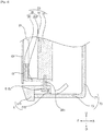
FIG. 2 is a sectional perspective view of the display apparatus taken along line S1-S1' ofFIG. 2 ; -
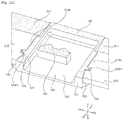
FIG. 3 is a rear bottom perspective view of the display apparatus ofFIG. 1 , showing the state in which a rear case is removed; -
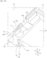
FIG. 4 is a sectional conceptual view of the display apparatus taken along line S3-S3' ofFIG. 3 ; -
FIG. 5 is an elevation view showing the upper surface of a sensing module support member and a sensing module and a partially enlarged elevation view showing a portion of the display apparatus in which the sensing module is disposed; -
FIG. 6 is a perspective view showing the state in which the sensing module support member and the sensing module ofFIG. 5 are separated from each other; -
FIG. 7 is a perspective view showing the state in which the sensing module support member and the sensing module ofFIG. 6 are coupled to each other; -
FIG. 8 is a perspective view of the sensing module ofFIG. 6 when viewed from a different side; -
FIG. 9 is a sectional perspective view of the sensing module taken along line S3-S3' ofFIG. 8 ; -
FIG. 10a is a sectional view of the sensing module taken along line S4-S4' ofFIG. 8 , showing the state in which the sensing module is coupled to the sensing module support member; -
FIGS. 10b and10c are sectional views of the sensing module taken along line S4-S4' ofFIG. 8 , according to other embodiments; -
FIG. 11a is a sectional perspective view of the sensing module taken along line S5-S5' ofFIG. 10a ; -
FIG. 11b is a sectional perspective view of the sensing module taken along line S5-S5' ofFIG. 10a , according to other embodiment; -
FIG. 12a is a sectional perspective view of the sensing module and the sensing module support member taken along line S6-S6' ofFIG. 10a ; and -
FIG. 12b is a sectional perspective view of the sensing module and the sensing module support member taken along line S6-S6' ofFIG. 10a , according to other embodiment. - [50] Exemplary embodiments of the present invention will be described with reference to the attached drawings.
- [51] In the following description, the terms "forward," "rearward," "leftward," "rightward," "upward," and "downward," which indicate directions, are defined based on forward (F), rearward (R), leftward (Le), rightward (Ri), upward (U), and downward (D) directions as illustrated in the drawings. In this specification, the direction in which a display panel outputs an image is defined as the forward direction, and the direction in which a sensing module is disposed is defined as the downward direction. However, these definitions are given only for clear understanding of the present invention, and the directions may be defined differently depending on the circumstances.
- [52] In the following description, the terms "first," "second," "third," and "fourth" are used only to avoid confusion between designated components, and do not indicate the sequence or importance of the components or the relationships between the components. For example, a display apparatus may include only a second component, and may lack a first component.
- [53] Referring to
FIGS. 1 to 4 , a display apparatus according to an embodiment of the present invention includes adisplay panel 10 for displaying an image. Thedisplay panel 10 outputs the image forward. For example, thedisplay panel 10 may be a thin film transistor liquid-crystal display (TFT-LCD) panel. - [54] In the case in which the
display panel 10 is an LCD panel, the display apparatus may include abacklight module 20 disposed at the rear of thedisplay panel 10. Thebacklight module 20 emits light to thedisplay panel 10. Thebacklight module 20 is fixed to amain frame 30. Thebacklight module 20 is disposed between thedisplay panel 10 and themain frame 30. For example, thebacklight module 20 may include a cold cathode fluorescent lamp (CCFL) or a light emitting diode (LED) as a light source. - [55] The display apparatus includes a
main frame 30 disposed at the rear of thedisplay panel 10. Themain frame 30 is disposed so as to be spaced apart from thedisplay panel 10. The display apparatus includes a supporter disposed in contact with an external wall or an external floor for supporting the display apparatus. The supporter may be fixed to themain frame 30 in order to support themain frame 30. Themain frame 30 supports other parts of the display apparatus. The load of other parts of the display apparatus is transferred to the supporter via themain frame 30, and is transferred to the external wall or the external floor via the supporter. - [56] The display apparatus includes a
support member 50 disposed along the edge of thedisplay panel 10. Thesupport member 50 is coupled and fixed to themain frame 30. The rear side part of thesupport member 50 is coupled and fixed to the side end of the edge of themain frame 30. - [57] The
support member 50 may be disposed at the upper side, the lower side, the left side, and the right side of thedisplay panel 10. Thesupport member 50 includes a lowerside support member 50a disposed so as to extend along the lower side end of thedisplay panel 10, an upperside support member 50b disposed so as to extend along the upper side end of thedisplay panel 10, a leftside support member 50d disposed so as to extend along the left side end of thedisplay panel 10, and a rightside support member 50c disposed so as to extend along the right side end of thedisplay panel 10. The upperside support member 50b, the lowerside support member 50a, the leftside support member 50d, and the rightside support member 50c may be provided as separate parts. - [58] The
support member 50 includes a sensingmodule support member 51 for supporting asensing module 100, a description of which will follow. Thesupport member 50 includes a displaypanel support member 55 for supporting thedisplay panel 10. At least one selected from among the upperside support member 50b, the lowerside support member 50a, the leftside support member 50d, and the rightside support member 50c constitutes the displaypanel support member 55. In this embodiment, the lowerside support member 50a constitutes the sensingmodule support member 51, and the upperside support member 50b, the leftside support member 50d, and the rightside support member 50c constitute the displaypanel support member 55. - [59] The display apparatus includes a
rear case 70 that defines the rear surface of the display apparatus. Therear case 70 is fixed to themain frame 30. Therear case 70 may cover the rear surface of themain frame 30. Therear case 70 covers the rear surface of acontroller 80, a description of which will follow. - [60] The display apparatus includes a
controller 80 for controlling the output of an image. Thecontroller 80 is fixed to themain frame 30. The display apparatus may include a speaker (not shown). Thecontroller 80 may control an acoustic signal. Thecontroller 80 may control the supply of electric power to thedisplay panel 10. Thecontroller 80 may include an input unit (not shown) for allowing a user to manipulate the display apparatus. Thecontroller 80 may include a main printed circuit board (PCB) (not shown) for processing information. - [61] The display apparatus includes a
sensing module 100 for receiving a signal from an external remote controller. The signal from the external remote controller may be an optical signal. For example, the signal from the external remote controller may be an infrared (IR) signal. Upon receiving the optical signal, thecontroller 80 may control the display apparatus. - [62] Referring to
FIGS. 2 to 4 , themain frame 30 is coupled to thesupport member 50 to support thesupport member 50. Themain frame 30 is coupled to the sensingmodule support member 51 to support the sensingmodule support member 51. Themain frame 30 is coupled to the displaypanel support member 55 to support the displaypanel support member 55. Themain frame 30 fixes thebacklight module 20 to support thebacklight module 20. Themain frame 30 fixes thecontroller 80 to support thecontroller 80. Themain frame 30 may dissipate heat generated in the display apparatus. - [63] The
main frame 30 includes amain plate 31. Themain plate 31 is disposed at the rear of thedisplay panel 10 so as to be spaced apart from thedisplay panel 10. Themain plate 31 is disposed at the rear of thebacklight module 20. Themain plate 31 has a predetermined thickness in the forward-rearward direction. Themain plate 31 may be coupled to thesupport member 50 to support thesupport member 50. Themain plate 31 is coupled to the displaypanel support member 55 to support the displaypanel support member 55. - [64] In this embodiment, the
main plate 31 extends in the leftward-rightward direction so as to interconnect the leftside support member 50d and the rightside support member 50c. Themain plate 31 extends toward the upperside support member 50b in the upward direction. Themain plate 31 extends to a position spaced apart from the lowerside support member 50a in the downward direction. Themain plate 31 is coupled to the leftside support member 50d and the rightside support member 50c to support the leftside support member 50d and the rightside support member 50c. Themain plate 31 is coupled to the upperside support member 50b to support the upperside support member 50b. Themain plate 31 is coupled to the displaypanel support member 55 to support the displaypanel support member 55. - [65] The
main frame 30 includes aheat dissipation plate 33. Theheat dissipation plate 33 may be thicker than themain plate 31 in the forward-rearward direction. Theheat dissipation plate 33 is disposed at the rear of themain plate 31. Theheat dissipation plate 33 is coupled to themain plate 31. Theheat dissipation plate 33 may protrude forward in the state of surrounding the side end of the edge of themain plate 31 that is adjacent to the sensingmodule support member 51. In this embodiment, theheat dissipation plate 33 defines a portion protruding forward while surrounding the lower side end of themain plate 31. Theheat dissipation plate 33 is coupled to the sensingmodule support member 51 to support the sensingmodule support member 51. In this embodiment, theheat dissipation plate 33 is coupled to the lowerside support member 50a. Theheat dissipation plate 33 is fastened to the sensingmodule support member 51 via afastening member 38c. - [66] The
main frame 30 includes apanel support unit 35. Thepanel support unit 35 fixes the rear surface of the edge of thedisplay panel 10. Thepanel support unit 35 is coupled to thedisplay panel 10 via anattachment member 15 to support thedisplay panel 10. Thepanel support unit 35 is disposed at a portion of the edge of the display panel at which the sensing module support member is disposed. Thepanel support unit 35 is disposed along the side end of thedisplay panel 10 in the direction in which the sensingmodule support member 51 is disposed, among the front, rear, left, and right side ends of thedisplay panel 10. The side end of thedisplay panel 10 in the direction in which the sensingmodule support member 51 is disposed, among the front, rear, left, and right side ends of thedisplay panel 10, is fixed to the displaypanel support member 55 via an attachment member. - [67] The
panel support unit 35 includes avertical part 351 disposed so as to be parallel to the rear surface of thedisplay panel 10. Thepanel support unit 35 includes ahorizontal part 353 protruding from thevertical part 351 and extending in the rearward direction. A single member may be bent in order to form thevertical part 351 and thehorizontal part 353 of thepanel support unit 35. - [68] The
vertical part 351 may have a predetermined thickness in the forward-rearward direction. Thevertical part 351 defines the front surface of thepanel support unit 35 that faces the rear surface of thedisplay panel 10. Anattachment member 15 is coupled to the front surface of thevertical part 351, and the rear surface of thedisplay panel 10 is coupled to the front surface of theattachment member 15, whereby the rear surface of thedisplay panel 10 is fixed by thevertical part 351. For example, an ultraviolet (UV) curable resin, such as an epoxy resin, may be used as theattachment member 15. Thevertical part 351 is disposed at the rear of the side end of the edge of thedisplay panel 10. Thevertical part 351 is disposed at the rear of thedisplay panel 10 so as to be as high as a predetermined height of the side end of the display panel. Thevertical part 351 is disposed along the side end of thedisplay panel 10 in the direction in which the sensingmodule support member 51 is disposed, among the front, rear, left, and right side ends of thedisplay panel 10. The side end of thedisplay panel 10 in the direction in which the displaypanel support member 55 is disposed, among the front, rear, left, and right side ends of thedisplay panel 10, is fixed to the displaypanel support member 55, rather than to thevertical part 351. - [69] The
horizontal part 353 may have a predetermined thickness in the upward-downward direction. Thehorizontal part 353 defines the lower surface of thepanel support unit 35 that faces the upper surface of the sensingmodule support member 51. Thehorizontal part 353 is disposed at one side end of themain frame 30. Thehorizontal part 353 may be fixed in the state of being in contact with one side end of theheat dissipation plate 33. Thehorizontal part 353 may be fastened to one end of theheat dissipation plate 33 via afastening member 38a. - [70] The
horizontal part 353 protrudes further forward than the front surfaces of themain plate 31 and theheat dissipation plate 33. Thevertical part 351 is connected to the front end of thehorizontal part 353. A space is defined between the front surfaces of themain plate 31 and theheat dissipation plate 33 and the rear surface of thevertical part 351. Thebacklight module 20 is disposed in this space. Thepanel support unit 35 supports thebacklight module 20. - [71] In this embodiment, the
panel support unit 35 is disposed at the rear of the lower part of thedisplay panel 10. Thevertical part 351 is disposed so as to be parallel to the lower part of thedisplay panel 10. Thehorizontal part 353 is disposed at the lower side end of themain frame 30. Thehorizontal part 353 is disposed at the lower side end of theheat dissipation plate 33. Thebacklight module 20 is disposed at the upper side of thehorizontal part 353 such that thebacklight module 20 is supported. - [72] The
main frame 30 may include anauxiliary frame 37. Theauxiliary frame 37 fixes other parts to themain frame 30. For example, theauxiliary frame 37 may be fastened to the rear surface of theheat dissipation plate 33, and the main PCB, the speaker, etc. may be fixed to and supported by theauxiliary frame 37. Theauxiliary frame 37 may be disposed between theheat dissipation plate 33 and therear case 70. - [73] The
rear case 70 may include arear part 71 that defines the rear surface of the display apparatus and alower part 73 that defines the lower surface of the display apparatus. Therear case 70 is fixed to themain frame 30. Therear case 70 may be fastened to theheat dissipation plate 33. Therear case 70 may be configured to cover only a portion of the rear surface of the display apparatus. An inner space is defined between the inner surface of therear case 70 and themain frame 30, and thecontroller 80 is disposed in the inner space. - [74] The display
panel support member 55 extends along the edge of thedisplay panel 10. The displaypanel support member 55 is fixed to themain frame 30. The displaypanel support member 55 fixes the edge of thedisplay panel 10. - [75] The display
panel support member 55 includes anedge part 551 that defines the front surface of the edge of thedisplay panel 10 and a displaypanel fixing part 553 for fixing the edge of thedisplay panel 10. The displaypanel fixing part 553 is disposed at the rear of the edge of thedisplay panel 10. An attachment member may be coupled to the front surface of the displaypanel fixing part 553, and the rear surface of thedisplay panel 10 may be coupled to the front surface of the attachment member, whereby the displaypanel support member 55 may support the edge of thedisplay panel 10. - [76] The display
panel support member 55 is disposed at the edge of thedisplay panel 10, excluding the portion at which the sensingmodule support member 51 is disposed. In this embodiment, the displaypanel support member 55 is disposed at the edge of thedisplay panel 10 excluding the lower part of thedisplay panel 10. - [77] Referring to
FIGS. 3 to 7 , the sensingmodule support member 51 extends along the edge of thedisplay panel 10. The sensingmodule support member 51 is disposed at only one side of thedisplay panel 10 in the forward, rearward, leftward, and rightward directions. The sensingmodule support member 51 may be disposed at the edge of thedisplay panel 10 excluding the portion at which the displaypanel support member 55 is disposed. In this embodiment, the sensingmodule support member 51 extends along the lower part of thedisplay panel 10. - [78] The sensing
module support member 51 includes afront part 511 that defines the front surface thereof and extends along the edge of the display panel. In this embodiment, thefront part 511 is disposed at the lower side of thedisplay panel 10. Thefront part 511 has a transmissionpart disposition hole 511a formed therethrough in the forward-rearward direction. A portion of thefront part 511 that is adjacent to thedisplay panel 10 is recessed in the direction perpendicular to the forward-rearward direction, whereby the transmissionpart disposition hole 511a is formed. In this embodiment, the portion of thefront part 511 that is adjacent to thedisplay panel 10 is the upper portion of thefront part 511, and the upper portion of thefront part 511 is recessed downward, whereby the transmissionpart disposition hole 511a is formed. - [79] The sensing
module support member 51 includes arear protrusion 515 protruding toward the rear of thefront part 511 so as to be coupled to themain frame 30. Therear protrusion 515 extends along the edge of thedisplay panel 10. The front end of therear protrusion 515 is coupled to the rear surface of thefront part 511. In this embodiment, therear protrusion 515 extends in the leftward-rightward direction. Therear protrusion 515 has a modulecabinet disposition recess 515a formed at the rear of the transmissionpart disposition hole 511a. A portion of therear protrusion 515 is recessed forward, whereby the modulecabinet disposition recess 515a is formed. The rear end of therear protrusion 515 is recessed forward, whereby the modulecabinet disposition recess 515a is formed. Therear protrusion 515 may be formed in a separated state by the modulecabinet disposition recess 515a. - [80] The sensing
module support member 51 is fixed to themain frame 30. Therear protrusion 515 includes a fixingpart 515c fixed to themain frame 30. In this embodiment, the fixingpart 515c protrudes upward. The fixingpart 515c protrudes further upward than the remaining part of therear protrusion 515. The upper surface of the fixingpart 515c contacts the lower surface of themain frame 30. The fixingpart 515c is fixed to themain frame 30 via afastening member 38c. The fixingpart 515c protrudes upward, and the upper surface of the remaining part of therear protrusion 515 is disposed so as to be spaced apart from the lower surface of themain frame 30. In addition, the upper end of thefront part 511 is disposed so as to be spaced apart from the lower end of thedisplay panel 10. - [81] Referring to
FIGS. 5 to 12b , thesensing module 100 includes asubstrate 110, on which light receivingparts light emitting part 170, a description of which will follow, is disposed at thesubstrate 110. Asensing module controller 180, a description of which will follow, is disposed at thesubstrate 110. Thesubstrate 110 is inserted and disposed between opposite side surfaces of amodule cabinet 120, a description of which will follow. Thelight receiving parts substrate 110. Thelight emitting part 170 and thesensing module controller 180 are fixed to thesubstrate 110. The front portion of thesubstrate 110 is inserted into themodule cabinet 120, and the rear portion of thesubstrate 110 is disposed at the rear of themodule cabinet 120 in the state of not being inserted into themodule cabinet 120. The rear portion of thesubstrate 110 protrudes toward the rear of themodule cabinet 120. The rear portion of thesubstrate 110 is disposed in the same plane as the front portion thereof. The rear portion of thesubstrate 110 is angled horizontally from the front portion thereof. - [82] The
sensing module 100 includes amodule cabinet 120, which defines opposite side surfaces thereof. Themodule cabinet 120 defines at least a portion of the outer surface of thesensing module 100, e.g. opposite side surfaces of thesensing module 100. Themodule cabinet 120 is inserted and fixed in the modulecabinet disposition recess 515a. Themodule cabinet 120 is coupled to the sensingmodule support member 51 such that thesensing module 100 is supported. - [83] The
module cabinet 120 includes a pair ofside parts 121, which are spaced apart from each other to define left and right side surfaces thereof. Thesubstrate 110 may be disposed at the upper part of themodule cabinet 120 between the opposite side surfaces of themodule cabinet 120. Thesubstrate 110 is disposed between theside parts 121. Themodule cabinet 120 includes alower part 123 disposed at the lower side of thesubstrate 110 so as to be spaced apart from thesubstrate 110. Themodule cabinet 120 may include anupper part 125 that defines the upper surface thereof at the front of thesubstrate 110. The inner space of thesensing module 110 is partitioned by theside parts 121, thelower part 123, and thesubstrate 110. The upper end of theupper part 125 may be disposed in substantially the same horizontal plane as the upper end of thefront part 511, or may be disposed higher than the upper end of thefront part 511. The lower end of thelower part 123 may be disposed lower than the lower end of thefront part 511. - [84] The
sensing module 100 includes atransmission part 140, which is disposed in the transmissionpart disposition hole 511a. Thetransmission part 140 transfers light incident to a front of thesensing module 100. Thetransmission part 140 receives light incident to a front surface of thetransmission part 140 and transfers the light inward toward thelight receiving parts transmission part 140 is disposed in substantially the same plane as the front surface of thefront part 511. In the case in which the front surface of thetransmission part 140 has the same color as the front surface of thefront part 511, thetransmission part 140 andfront part 511 may appear to be integrated. - [85] The
transmission part 140 is disposed at the front end of themodule cabinet 120. Thetransmission part 140 is connected to the front ends of theside parts 121, thelower part 123, and theupper part 125. The inner space of themodule cabinet 120 is defined at the rear of thetransmission part 140. - [86] The
sensing module 100 includeslight receiving parts transmission part 140. Thelight receiving parts substrate 110. Thelight receiving parts substrate 110. Thelight receiving parts substrate 110. Thelight receiving parts infrared light receiver 150 for receiving infrared light for remote control. Thelight receiving parts illumination sensor 160 for sensing illumination intensity of the transmitted light. Theillumination sensor 160 senses illumination of the transmitted light. A plurality of infraredlight receivers 150 may be provided. The infraredlight receivers 150 may include a firstinfrared light receiver 150a and a secondinfrared light receiver 150b, which are arranged horizontally. When viewed from the front, the infraredlight receivers 150 and theillumination sensor 160 are arranged horizontally. Theillumination sensor 160, the firstinfrared light receiver 150a, and the secondinfrared light receiver 150b may be sequentially arranged horizontally in the state of being spaced apart from each other. - [87] The
sensing module 100 includes alight emitting part 170 for emitting light forward. The light emitted by thelight emitting part 170 passes through thetransmission part 140. Thelight emitting part 170 is disposed at thesubstrate 110. Thelight emitting part 170 is disposed at the lower surface of thesubstrate 110. Thelight emitting part 170 is disposed at the front portion of thesubstrate 110. Thelight emitting part 170 is disposed further forward than theinfrared light receivers light emitting part 170 is disposed at the front of the firstinfrared light receiver 150a. Theillumination sensor 160, the firstinfrared light receiver 150a, and the secondinfrared light receiver 150b are horizontally arranged in the rear space of the inner space of themodule cabinet 120. Thelight emitting part 170 is disposed in the front space of the inner space of themodule cabinet 120. For example, thelight emitting part 170 may include an LED. - [88] The
sensing module 100 includes asensing module controller 180 for processing information sensed by thelight receiving parts sensing module controller 180 processes information sensed by theillumination sensor 160. Thesensing module controller 180 controls the operation of thelight emitting part 170. Thesensing module controller 180, thelight receiving parts light emitting part 170 are electrically connected to one another. Wires for electrical connection are disposed on thesubstrate 110. - [89] The
sensing module controller 180 is disposed at thesubstrate 110. Thesensing module controller 180 is disposed on the upper surface of thesubstrate 110. Thesensing module controller 180 is disposed at the rear portion of thesubstrate 110. The rear portion of thesubstrate 110 extends to the rear of themain frame 30. Thesensing module controller 180 may be disposed at the rear portion of thesubstrate 110, whereby thesensing module controller 180 may be disposed at the rear of themain frame 30. The rear portion of thesubstrate 110 is angled from the front portion of thesubstrate 110 in the leftward direction or in the rightward direction. When viewed from above, thesensing module controller 180 extends in the leftward-rightward direction. The length of thesensing module controller 180 in the leftward-rightward direction is longer than the length of thesensing module controller 180 in the front-rear direction. As a result, it is possible to reduce the thickness of the display apparatus in the forward-rearward direction. - [90] Hereinafter, the structure in which the
module cabinet 120 and the sensingmodule support member 51 are coupled to each other and the structure in which themodule cabinet 120 and thesubstrate 110 are coupled to each other will be described with reference toFIGS. 6 to 12b . - [91] The sensing
module support member 51 supports thesensing module 100. Therear protrusion 515 supports themodule cabinet 120. Themodule cabinet 120 is inserted and fixed in the modulecabinet disposition recess 515a from the rear to the front thereof. Thetransmission part 140 is inserted and located in the transmissionpart disposition hole 511a from the rear to the front thereof. That is, in the assembly process, thesensing module 100 is fixedly disposed by inserting thesensing module 100 into the rear protrusion 414 of the sensingmodule support member 51 from the rear to the front thereof, without using an additional fastening member. - [92] The transmission
part disposition hole 511a is formed so as to be open at the upper side thereof. The front portions of theside parts 121 are inserted into the transmissionpart disposition hole 511a. The width of the transmissionpart disposition hole 511a in the leftward-rightward direction corresponds to the width of themodule cabinet 120 in the leftward-rightward direction. The front portion of thelower part 123 is inserted into the transmissionpart disposition hole 511a. Theupper part 125 is disposed in the upper opening of the transmissionpart disposition hole 511a. - [93] The width of the module
cabinet disposition recess 515a in the leftward-rightward direction corresponds to the width of themodule cabinet 120 in the leftward-rightward direction. The opposite side surfaces of themodule cabinet 120 contact the side end of therear protrusion 515, which partitions the modulecabinet disposition recess 515a. - [94] The
rear protrusion 515 and themodule cabinet 120 are configured to be coupled together by aninsertion groove 130a engaged with aninsertion part 515b. Theinsertion groove 130a is provided at one of therear protrusion 515 or themodule cabinet 120 and theinsertion part 515b is provided at the other of therear protrusion 515 or themodule cabinet 120. One of therear protrusion 515 or at least one of theside parts 121 is provided with theinsertion groove 130a configured to be engaged with at least oneinsertion part 515b disposed on the other of therear protrusion 515 or the at least one of theside parts 121. At the point at which therear protrusion 515 contacts themodule cabinet 120 in the leftward-rightward direction, one selected from between therear protrusion 515 and themodule cabinet 120 is provided with theinsertion groove 130a, which extends in the forward-rearward direction, and the other is provided with theinsertion part 515b, which extends in the forward-rearward direction so as to be engaged with theinsertion groove 130a. One selected from between therear protrusion 515 and theside parts 121 is provided withinsertion grooves 130a, which extend in the forward-rearward direction, and the other is provided withinsertion parts 515b, which extend in the forward-rearward direction so as to be engaged with theinsertion grooves 130a. In the assembly process, theinsertion part 515b slides along theinsertion groove 130a so as to be engaged with theinsertion groove 130a. A pair including aninsertion part 515b and aninsertion groove 130a, which are engaged with each other, is disposed at each of the left and right sides of themodule cabinet 120. - [95] The one selected from between the
rear protrusion 515 and themodule cabinet 120 that is provided with theinsertion groove 130a may include afirst bracket 131 protruding laterally and defining the upper surface of theinsertion groove 130a. The one selected from between therear protrusion 515 and themodule cabinet 120 that is provided with theinsertion groove 130a may include asecond bracket 133 protruding laterally and defining the lower surface of theinsertion groove 130a. Thefirst bracket 131 and thesecond bracket 133 are disposed so as to be spaced apart from each other in the upward-downward direction. Theinsertion groove 130a is formed between thefirst bracket 131 and thesecond bracket 133. Thefirst bracket 131 partitions the upper side of theinsertion groove 130a. Thesecond bracket 133 partitions the lower side of theinsertion groove 130a. Thefirst bracket 131 extends in the forward-rearward direction. Thesecond bracket 133 extends in the forward-rearward direction. As a result, thesensing module 100 may slide from the rear to the front of therear protrusion 515, whereby thesensing module 100 may be fixed. - [96] One of a first surface that partitions a side surface of the
insertion groove 130a or a second surface that partitions a side surface of theinsertion part 515b is provided with a lateral module cabinet catching recess 515b1 configured to be engaged with a modulecabinet catching protrusion 135 provided at the other of the first surface or the second surface. One selected from between the surface that partitions the side surface of theinsertion groove 130a and the surface that partitions the side surface of theinsertion part 515b is provided with the module cabinet catching recess 515b1, which is formed laterally, and the other is provided with the modulecabinet catching protrusion 135, which is engaged with the module cabinet catching recess 515b1. When thesensing module 100 slides from the rear to the front of therear protrusion 515, therefore, the modulecabinet catching protrusion 135 is engaged with the module cabinet catching recess 515b1, whereby thesensing module 100 is fixed such that thesensing module 100 is prevented from escaping rearward from therear protrusion 515. - [97] In this embodiment referring to
Fig. 5 to 10a , theinsertion part 515b is formed on therear protrusion 515, and theinsertion groove 130a is formed in thesensing module 100. Thefirst bracket 131 is formed at themodule cabinet 120. Thesecond bracket 133 is formed at themodule cabinet 120. - [98] In other embodiment referring to
Fig. 10b , theinsertion part 515b is formed on thesensing module 100, and theinsertion groove 130a is formed in therear protrusion 515. Thefirst bracket 131 is formed at the rear protrusion 515'. Thesecond bracket 133 is formed at therear protrusion 515. - [99] In this embodiment referring to
Fig. 5 to 10a and12a , the module cabinet catching recess 515b1 is formed in therear protrusion 515, and the modulecabinet catching protrusion 135 is formed on themodule cabinet 120. In this embodiment referring toFig. 5 to 10a and12a , the module cabinet catching recess 515b1 is formed in a surface that partitions a side surface of theinsertion part 515b, and the modulecabinet catching protrusion 135 is formed on a surface that partitions a side surface of theinsertion groove 130a. - [100] In other embodiment referring to
Fig. 12b , the module cabinet catching recess 515b1 is formed in themodule cabinet 120, and the modulecabinet catching protrusion 135 is formed on therear protrusion 515. In other embodiment referring toFig. 12b , the module cabinet catching recess 515b1 is formed in a surface that partitions a side surface of theinsertion groove 130a, and the modulecabinet catching protrusion 135 is formed on a surface that partitions a side surface of theinsertion part 515b. - [101] The module cabinet catching recess 515b1 is formed in the side end of the
insertion part 515b. The modulecabinet catching protrusion 135 is disposed in theinsertion groove 130a. The modulecabinet catching protrusion 135 is disposed between thefirst bracket 131 and thesecond bracket 133. - [102] In this embodiment, the
sensing module 100 includes a modulecabinet fixing part 130 for fixing themodule cabinet 120 to therear protrusion 515. Themodule cabinet 120 includes a modulecabinet fixing part 130. The modulecabinet fixing part 130 includes afirst bracket 131. The modulecabinet fixing part 130 includes asecond bracket 133. The modulecabinet fixing part 130 includes a modulecabinet catching protrusion 135. A pair of modulecabinet fixing parts 130 is disposed at the opposite side surfaces of themodule cabinet 120. A pair offirst brackets 131 protrudes from opposite side surfaces of themodule cabinet 120. A pair ofsecond brackets 133 protrudes from opposite side surfaces of themodule cabinet 120. A pair ofinsertion grooves 130a is formed in opposite side surfaces of themodule cabinet 120. A pair ofinsertion parts 515b is disposed at opposite sides of the modulecabinet disposition recess 515a. Each of theinsertion parts 515b is provided with a module cabinet catching recess 515b1. - [103] The width between the left and right inner surfaces of the
module cabinet 120 corresponds to the width of the front portion of thesubstrate 110 in the leftward-rightward direction. The front portion of thesubstrate 110 contacts the inner surfaces of the opposite sides of themodule cabinet 120. - [104] The
substrate 110 and themodule cabinet 120 are configured to be coupled together by asubstrate insertion groove 127 engaged with asubstrate insertion part 111. Thesubstrate insertion groove 127 is provided at one of thesubstrate 110 or themodule cabinet 120 and thesubstrate insertion part 111 is provided at the other of thesubstrate 110 or themodule cabinet 120. Thesubstrate insertion groove 127 and thesubstrate insertion part 111 extend in a forward-rearward direction. thesubstrate 110 is inserted between theside parts 121. One of thesubstrate 110 or at least one of theside parts 121 is provided with thesubstrate insertion groove 127 configured to engage with thesubstrate insertion part 111 disposed on the other of thesubstrate 110 or the at least one of theside parts 121. At the point at which thesubstrate 110 contacts themodule cabinet 120 in the leftward-rightward direction, one selected from between thesubstrate 110 and themodule cabinet 120 is provided with thesubstrate insertion groove 127, which extends in the forward-rearward direction, and the other is provided with thesubstrate insertion part 111, which extends in the forward-rearward direction so as to be engaged with thesubstrate insertion groove 127. One selected from between the substrate and the side parts is provided with substrate insertion grooves, which extend in the forward-rearward direction, and the other is provided with substrate insertion parts, which extend in the forward-rearward direction so as to be engaged with the substrate insertion grooves. In the assembly process, thesubstrate insertion part 111 slides along thesubstrate insertion groove 127 so as to be engaged with thesubstrate insertion groove 127. A pair including asubstrate insertion part 111 and asubstrate insertion groove 127, which are engaged with each other, is disposed at each of opposite sides of themodule cabinet 120. - [105] The one selected from between the
substrate 110 and themodule cabinet 120 that is provided with thesubstrate insertion groove 127 may include athird bracket 126a protruding laterally and defining the upper surface of thesubstrate insertion groove 127. The one selected from between thesubstrate 110 and themodule cabinet 120 that is provided with thesubstrate insertion groove 127 may include afourth bracket 126b protruding laterally and defining the lower surface of thesubstrate insertion groove 127. Thethird bracket 126a and thefourth bracket 126b are disposed so as to be spaced apart from each other in the upward-downward direction. Thesubstrate insertion groove 127 is formed between thethird bracket 126a and thefourth bracket 126b. Thethird bracket 126a partitions the upper side of thesubstrate insertion groove 127. Thefourth bracket 126b partitions the lower side of thesubstrate insertion groove 127. Thethird bracket 126a extends in the forward-rearward direction. Thefourth bracket 126b extends in the forward-rearward direction. As a result, thesubstrate 110 may slide from the rear to the front of themodule cabinet 120, whereby thesubstrate 110 may be fixed. - [106] One of a first surface that partitions a side surface of the
substrate insertion groove 127 or a second surface that partitions a side surface of thesubstrate insertion part 111 comprises asubstrate catching recess 110a, and the other of the first surface or the second surface comprises asubstrate catching protrusion 126c configured to be engaged with thesubstrate catching recess 110a. One selected from between the surface that partitions the side surface of thesubstrate insertion groove 127 and the surface that partitions the side surface of thesubstrate insertion part 111 is provided with thesubstrate catching recess 110a, which is formed laterally, and the other is provided with thesubstrate catching protrusion 126c, which is engaged with thesubstrate catching recess 110a. When thesubstrate 110 slides from the rear to the front of themodule cabinet 120, therefore, thesubstrate catching protrusion 126c is engaged with thesubstrate catching recess 110a, whereby thesubstrate 110 is fixed such that thesubstrate 110 is prevented from escaping rearward from themodule cabinet 120. - [107] In this embodiment referring to
Fig. 5 to 10a , thesubstrate insertion part 111 is formed on thesubstrate 110, and thesubstrate insertion groove 127 is formed in themodule cabinet 120. In this embodiment referring toFig. 5 to 10a , thethird bracket 126a is formed at themodule cabinet 120, and Thefourth bracket 126b is formed at themodule cabinet 120. - [108] In other embodiment referring to
Fig. 10c , thesubstrate insertion part 111 is formed on themodule cabinet 120, and thesubstrate insertion groove 127 is formed in thesubstrate 110. In other embodiment referring toFig. 10c , thethird bracket 126a is formed at thesubstrate 110, and thefourth bracket 126b is formed at thesubstrate 110. - [109] In this embodiment referring to
Fig. 5 to 10a and11a , thesubstrate catching recess 110a is formed in thesubstrate 110, and thesubstrate catching protrusion 126c is formed on themodule cabinet 120. In this embodiment referring toFig. 5 to 10a and 11a, thesubstrate catching recess 110a is formed in a surface that partitions a side surface of thesubstrate insertion part 111, and thesubstrate catching protrusion 126c is formed on a surface that partitions a side surface of thesubstrate insertion groove 127. Thesubstrate catching protrusion 126c is disposed in thesubstrate insertion groove 127. Thesubstrate catching protrusion 126c is disposed between thethird bracket 126a and thefourth bracket 126b. - [110] In other embodiment referring to
Fig. 11b , thesubstrate catching recess 110a is formed in themodule cabinet 120, and thesubstrate catching protrusion 126c is formed on thesubstrate 110. In other embodiment referring toFig. 11b , thesubstrate catching recess 110a is formed in a surface that partitions a side surface of thesubstrate insertion groove 127, and thesubstrate catching protrusion 126c is formed on a surface that partitions a side surface of thesubstrate insertion part 111. Thesubstrate catching recess 110a is disposed in thesubstrate insertion groove 127. Thesubstrate catching recess 110a is disposed between thethird bracket 126a and thefourth bracket 126b. - [111] In this embodiment, the
sensing module 100 includes asubstrate fixing part 126 for fixing thesubstrate 110 to themodule cabinet 120. Themodule cabinet 120 includes asubstrate fixing part 126. Thesubstrate fixing part 126 includes athird bracket 126a. Thesubstrate fixing part 126 includes afourth bracket 126b. Thesubstrate fixing part 126 includes asubstrate catching protrusion 126c. A pair ofsubstrate fixing parts 130 is disposed at opposite side surfaces of themodule cabinet 120. A pair ofthird brackets 126a protrudes from the inner surfaces of the opposite sides of themodule cabinet 120. A pair offourth brackets 126b protrudes from the inner surfaces of the opposite sides of themodule cabinet 120. A pair ofsubstrate insertion grooves 127 is formed in the inner surfaces of the opposite sides of themodule cabinet 120. A pair ofsubstrate insertion parts 111 is disposed at opposite sides of thesubstrate 110. Each of thesubstrate insertion parts 111 is provided with asubstrate catching recess 110a. - [112] In this embodiment, each of the
substrate insertion parts 111 is further provided at the side end thereof with asubstrate catching protrusion 110b, in addition to thesubstrate catching recess 110a. Themodule cabinet 120 is further provided in the inner surface thereof with asubstrate catching recess 126d, which is engaged with thesubstrate catching protrusion 110b. Specifically, thesubstrate 110 is provided with a firstsubstrate catching recess 110a and a secondsubstrate catching protrusion 110b, and themodule cabinet 120 is provided with a firstsubstrate catching protrusion 126c and a secondsubstrate catching recess 126d. The firstsubstrate catching recess 110a is engaged with the firstsubstrate catching protrusion 126c, and the secondsubstrate catching protrusion 110b is engaged with the secondsubstrate catching recess 126d.
Claims (11)
- A display apparatus comprising:a display panel (10);a main frame (30) disposed at a rear of the display panel (10);a sensing module support member (51) comprising:a front part (511) that defines a portion of a front surface of the display apparatus and extends along an edge of the display panel (10), wherein the front part (511) has a transmission part disposition hole (511a) formed therein in a forward-rearward direction; anda rear protrusion (515) protruding in a rearward direction from the front part (511) and coupled to the main frame (30), wherein the rear protrusion (515) has a module cabinet disposition recess (515a) formed therein which is positioned at a rear of the transmission part disposition hole (511a); anda sensing module (100) comprising:a module cabinet (120) coupled to the rear protrusion (515) and disposed in the module cabinet disposition recess (515a), wherein the module cabinet (120) includes a pair of side parts (121) which are spaced apart from each other to define left and right sides thereof;a transmission part (140) coupled to a front end of the module cabinet (120), disposed in the transmission part disposition hole (511a) and configured to transfer light incident to a front of the sensing module (100), anda substrate (110) inserted between the pair of side parts (121) and on which a light receiving part (150, 160) configured to sense the light transferred from the transmission part (140) is disposed,wherein one of the rear protrusion (515) or at least one of the pair of the side parts (121) is provided with an insertion groove (130a), the other of the rear protrusion (515) or the at least one of the pair of the side parts (121) is provided with an insertion part (515b) engaged with the insertion groove (130a).
- The display apparatus according to claim 1, wherein the one of the rear protrusion (515) or the at least one of the pair of the side parts (121) provided with the insertion groove (130a) comprises:a first bracket (131) protruding laterally and defining an upper surface of the insertion groove (130a); anda second bracket (133) protruding laterally and defining a lower surface of the insertion groove (130a).
- The display apparatus according to claim 1, wherein one of a first surface that partitions a side surface of the insertion groove (130a) or a second surface that partitions a side surface of the insertion part (515b) is provided with a lateral module cabinet catching recess (515b1) configured to be engaged with a module cabinet catching protrusion (135) provided at the other of the first surface or the second surface.
- The display apparatus according to claim 1, wherein the sensing module (100) comprises a sensing module controller (180) disposed on the substrate (110) and configured to process information sensed by the light receiving part (150, 160).
- The display apparatus according to claim 1, wherein the substrate (110) and the module cabinet (120) are configured to be coupled together by a substrate insertion groove (127) engaged with a substrate insertion part (111),wherein the substrate insertion groove (127) is provided at one of the substrate (110) or the module cabinet (120) and the substrate insertion part (111) is provided at the other of the substrate (110) or the module cabinet (120), andwherein the substrate insertion groove (127) and the substrate insertion part (111) extend in a forward-rearward direction.
- The display apparatus according to claim 5, wherein the one of the substrate (110) or the module cabinet (120) comprises the substrate insertion groove (127) further comprises:a third bracket (126a) protruding laterally and defining an upper surface of the substrate insertion groove(127); anda fourth bracket (126b) protruding laterally and defining a lower surface of the substrate insertion groove (127).
- The display apparatus according to claim 5, wherein one of a first surface that partitions a side surface of the substrate insertion groove (127) or a second surface that partitions a side surface of the substrate insertion part (111) comprises a substrate catching recess (110a), and the other of the first surface or the second surface comprises a substrate catching protrusion (126c) configured to be engaged with the substrate catching recess (110a).
- The display apparatus according to claim 1 or 4, wherein:a front portion of the substrate (110) is inserted into the module cabinet (120); anda rear portion of the substrate (110) protrudes toward a rear of the main frame (30) and is angled from the front portion.
- The display apparatus according to claim 8 when dependent on claim 4, wherein the sensing module controller (180) is disposed on the rear portion of the substrate (110).
- The display apparatus according to claim 1, whereinthe light receiving part (150, 160) comprises:a plurality of infrared light receivers (150) configured to receive infrared light for remote control of the display apparatus; andan illumination sensor (160) configured to sense illumination intensity of the light transferred from the transmission part (140),wherein the plurality of infrared light receivers (150) and the illumination sensor (160) are arranged horizontally when viewed from a front, andwherein the sensing module (100) further comprises a light emitting part (170) configured to emit light and disposed further forward than the infrared light receivers (150).
- The display apparatus according to claim 1, wherein one of the substrate (110) or at least one of the side parts (121) is provided with a substrate insertion groove (127) configured to engage with a substrate insertion part (111) disposed on the other of the substrate (121) or the at least one of the side parts (121).
Applications Claiming Priority (2)
| Application Number | Priority Date | Filing Date | Title |
|---|---|---|---|
| KR1020160130596A KR102767726B1 (en) | 2016-10-10 | 2016-10-10 | Display Apparatus |
| PCT/KR2017/011114 WO2018070748A1 (en) | 2016-10-10 | 2017-10-10 | Display apparatus |
Publications (3)
| Publication Number | Publication Date |
|---|---|
| EP3523959A1 EP3523959A1 (en) | 2019-08-14 |
| EP3523959A4 EP3523959A4 (en) | 2020-04-15 |
| EP3523959B1 true EP3523959B1 (en) | 2021-12-01 |
Family
ID=61829372
Family Applications (1)
| Application Number | Title | Priority Date | Filing Date |
|---|---|---|---|
| EP17861078.8A Active EP3523959B1 (en) | 2016-10-10 | 2017-10-10 | Display apparatus |
Country Status (5)
| Country | Link |
|---|---|
| US (1) | US10425607B2 (en) |
| EP (1) | EP3523959B1 (en) |
| KR (1) | KR102767726B1 (en) |
| CN (1) | CN110050460B (en) |
| WO (1) | WO2018070748A1 (en) |
Families Citing this family (2)
| Publication number | Priority date | Publication date | Assignee | Title |
|---|---|---|---|---|
| KR102817742B1 (en) * | 2018-12-26 | 2025-06-09 | 엘지디스플레이 주식회사 | Display device |
| CN113433732B (en) * | 2021-06-30 | 2022-09-13 | 厦门天马微电子有限公司 | Display module and display device |
Family Cites Families (12)
| Publication number | Priority date | Publication date | Assignee | Title |
|---|---|---|---|---|
| JPH0720759A (en) | 1993-06-22 | 1995-01-24 | Ricoh Co Ltd | Recyclable equipment |
| JPH0720759U (en) * | 1993-09-13 | 1995-04-11 | 三洋電機株式会社 | Television receiver |
| JP2000244135A (en) | 1999-02-19 | 2000-09-08 | Fujitsu General Ltd | Thin image display device |
| TW200939754A (en) | 2008-03-04 | 2009-09-16 | Qisda Corp | Display device |
| KR20100127475A (en) * | 2009-05-26 | 2010-12-06 | 엘지전자 주식회사 | Display device |
| EP2653911B1 (en) * | 2010-10-28 | 2016-04-27 | LG Electronics, Inc. | Display apparatus |
| EP2456198A1 (en) | 2010-11-23 | 2012-05-23 | Samsung Electronics Co., Ltd. | Display device comprising an infrared sensor |
| KR20120055433A (en) * | 2010-11-23 | 2012-05-31 | 삼성전자주식회사 | Display apparatus |
| JP2013125196A (en) * | 2011-12-15 | 2013-06-24 | Canon Inc | Display control apparatus and control method of display control apparatus |
| JP2013130831A (en) * | 2011-12-22 | 2013-07-04 | Sharp Corp | Display device and television receiver |
| CN102568333A (en) | 2012-01-16 | 2012-07-11 | 苏州佳世达电通有限公司 | Display device |
| JP5513568B2 (en) * | 2012-08-31 | 2014-06-04 | シャープ株式会社 | Display device and television receiver |
-
2016
- 2016-10-10 KR KR1020160130596A patent/KR102767726B1/en active Active
-
2017
- 2017-09-26 US US15/716,383 patent/US10425607B2/en active Active
- 2017-10-10 EP EP17861078.8A patent/EP3523959B1/en active Active
- 2017-10-10 CN CN201780075964.4A patent/CN110050460B/en active Active
- 2017-10-10 WO PCT/KR2017/011114 patent/WO2018070748A1/en not_active Ceased
Also Published As
| Publication number | Publication date |
|---|---|
| EP3523959A4 (en) | 2020-04-15 |
| EP3523959A1 (en) | 2019-08-14 |
| CN110050460B (en) | 2021-12-03 |
| KR20180039370A (en) | 2018-04-18 |
| US10425607B2 (en) | 2019-09-24 |
| US20180103228A1 (en) | 2018-04-12 |
| KR102767726B1 (en) | 2025-02-14 |
| WO2018070748A1 (en) | 2018-04-19 |
| CN110050460A (en) | 2019-07-23 |
Similar Documents
| Publication | Publication Date | Title |
|---|---|---|
| US11950383B2 (en) | Display apparatus | |
| US10884276B2 (en) | Display device with simplified appearance structure and improved coupling arrangement | |
| EP2339426B1 (en) | Display apparatus | |
| KR20130016630A (en) | Display device and led bar connection method thereof | |
| EP2887661A1 (en) | Apparatus for displaying a three-dimensional image | |
| EP3523959B1 (en) | Display apparatus | |
| JP5367867B2 (en) | Liquid crystal display device and television receiver | |
| KR20170100750A (en) | Structure for connecting printed circuit board and display apparatus having the same | |
| US11347278B2 (en) | Display device | |
| KR101256185B1 (en) | Lamp socket guide, lamp unit and backlight assembly having the same | |
| KR102564535B1 (en) | Display Apparatus | |
| KR20110017162A (en) | Display device | |
| JP2007298576A (en) | Indicator circuit unit having elastic rib and electronic device including the same | |
| WO2016013546A1 (en) | Display device and television receiver | |
| US20120146883A1 (en) | Display apparatus | |
| KR20170026938A (en) | Display device | |
| KR20170135432A (en) | Display device | |
| JP2008109355A (en) | Viewfinder |
Legal Events
| Date | Code | Title | Description |
|---|---|---|---|
| STAA | Information on the status of an ep patent application or granted ep patent |
Free format text: STATUS: THE INTERNATIONAL PUBLICATION HAS BEEN MADE |
|
| PUAI | Public reference made under article 153(3) epc to a published international application that has entered the european phase |
Free format text: ORIGINAL CODE: 0009012 |
|
| STAA | Information on the status of an ep patent application or granted ep patent |
Free format text: STATUS: REQUEST FOR EXAMINATION WAS MADE |
|
| 17P | Request for examination filed |
Effective date: 20190517 |
|
| AK | Designated contracting states |
Kind code of ref document: A1 Designated state(s): AL AT BE BG CH CY CZ DE DK EE ES FI FR GB GR HR HU IE IS IT LI LT LU LV MC MK MT NL NO PL PT RO RS SE SI SK SM TR |
|
| AX | Request for extension of the european patent |
Extension state: BA ME |
|
| DAV | Request for validation of the european patent (deleted) | ||
| DAX | Request for extension of the european patent (deleted) | ||
| A4 | Supplementary search report drawn up and despatched |
Effective date: 20200317 |
|
| RIC1 | Information provided on ipc code assigned before grant |
Ipc: H04N 5/64 20060101AFI20200311BHEP Ipc: H05K 5/00 20060101ALI20200311BHEP Ipc: H04N 5/44 20110101ALI20200311BHEP |
|
| REG | Reference to a national code |
Ref country code: DE Ref legal event code: R079 Ref document number: 602017050388 Country of ref document: DE Free format text: PREVIOUS MAIN CLASS: H04N0005640000 Ipc: H04N0021422000 |
|
| GRAP | Despatch of communication of intention to grant a patent |
Free format text: ORIGINAL CODE: EPIDOSNIGR1 |
|
| STAA | Information on the status of an ep patent application or granted ep patent |
Free format text: STATUS: GRANT OF PATENT IS INTENDED |
|
| RIC1 | Information provided on ipc code assigned before grant |
Ipc: H04N 5/64 20060101ALI20210623BHEP Ipc: H04N 21/422 20110101AFI20210623BHEP |
|
| INTG | Intention to grant announced |
Effective date: 20210713 |
|
| GRAS | Grant fee paid |
Free format text: ORIGINAL CODE: EPIDOSNIGR3 |
|
| GRAA | (expected) grant |
Free format text: ORIGINAL CODE: 0009210 |
|
| STAA | Information on the status of an ep patent application or granted ep patent |
Free format text: STATUS: THE PATENT HAS BEEN GRANTED |
|
| AK | Designated contracting states |
Kind code of ref document: B1 Designated state(s): AL AT BE BG CH CY CZ DE DK EE ES FI FR GB GR HR HU IE IS IT LI LT LU LV MC MK MT NL NO PL PT RO RS SE SI SK SM TR |
|
| REG | Reference to a national code |
Ref country code: GB Ref legal event code: FG4D |
|
| REG | Reference to a national code |
Ref country code: AT Ref legal event code: REF Ref document number: 1452912 Country of ref document: AT Kind code of ref document: T Effective date: 20211215 Ref country code: CH Ref legal event code: EP |
|
| REG | Reference to a national code |
Ref country code: IE Ref legal event code: FG4D |
|
| REG | Reference to a national code |
Ref country code: DE Ref legal event code: R096 Ref document number: 602017050388 Country of ref document: DE |
|
| REG | Reference to a national code |
Ref country code: LT Ref legal event code: MG9D |
|
| REG | Reference to a national code |
Ref country code: NL Ref legal event code: MP Effective date: 20211201 |
|
| REG | Reference to a national code |
Ref country code: AT Ref legal event code: MK05 Ref document number: 1452912 Country of ref document: AT Kind code of ref document: T Effective date: 20211201 |
|
| PG25 | Lapsed in a contracting state [announced via postgrant information from national office to epo] |
Ref country code: RS Free format text: LAPSE BECAUSE OF FAILURE TO SUBMIT A TRANSLATION OF THE DESCRIPTION OR TO PAY THE FEE WITHIN THE PRESCRIBED TIME-LIMIT Effective date: 20211201 Ref country code: LT Free format text: LAPSE BECAUSE OF FAILURE TO SUBMIT A TRANSLATION OF THE DESCRIPTION OR TO PAY THE FEE WITHIN THE PRESCRIBED TIME-LIMIT Effective date: 20211201 Ref country code: FI Free format text: LAPSE BECAUSE OF FAILURE TO SUBMIT A TRANSLATION OF THE DESCRIPTION OR TO PAY THE FEE WITHIN THE PRESCRIBED TIME-LIMIT Effective date: 20211201 Ref country code: BG Free format text: LAPSE BECAUSE OF FAILURE TO SUBMIT A TRANSLATION OF THE DESCRIPTION OR TO PAY THE FEE WITHIN THE PRESCRIBED TIME-LIMIT Effective date: 20220301 Ref country code: AT Free format text: LAPSE BECAUSE OF FAILURE TO SUBMIT A TRANSLATION OF THE DESCRIPTION OR TO PAY THE FEE WITHIN THE PRESCRIBED TIME-LIMIT Effective date: 20211201 |
|
| PG25 | Lapsed in a contracting state [announced via postgrant information from national office to epo] |
Ref country code: SE Free format text: LAPSE BECAUSE OF FAILURE TO SUBMIT A TRANSLATION OF THE DESCRIPTION OR TO PAY THE FEE WITHIN THE PRESCRIBED TIME-LIMIT Effective date: 20211201 Ref country code: PL Free format text: LAPSE BECAUSE OF FAILURE TO SUBMIT A TRANSLATION OF THE DESCRIPTION OR TO PAY THE FEE WITHIN THE PRESCRIBED TIME-LIMIT Effective date: 20211201 Ref country code: NO Free format text: LAPSE BECAUSE OF FAILURE TO SUBMIT A TRANSLATION OF THE DESCRIPTION OR TO PAY THE FEE WITHIN THE PRESCRIBED TIME-LIMIT Effective date: 20220301 Ref country code: LV Free format text: LAPSE BECAUSE OF FAILURE TO SUBMIT A TRANSLATION OF THE DESCRIPTION OR TO PAY THE FEE WITHIN THE PRESCRIBED TIME-LIMIT Effective date: 20211201 Ref country code: HR Free format text: LAPSE BECAUSE OF FAILURE TO SUBMIT A TRANSLATION OF THE DESCRIPTION OR TO PAY THE FEE WITHIN THE PRESCRIBED TIME-LIMIT Effective date: 20211201 Ref country code: GR Free format text: LAPSE BECAUSE OF FAILURE TO SUBMIT A TRANSLATION OF THE DESCRIPTION OR TO PAY THE FEE WITHIN THE PRESCRIBED TIME-LIMIT Effective date: 20220302 Ref country code: ES Free format text: LAPSE BECAUSE OF FAILURE TO SUBMIT A TRANSLATION OF THE DESCRIPTION OR TO PAY THE FEE WITHIN THE PRESCRIBED TIME-LIMIT Effective date: 20211201 |
|
| PG25 | Lapsed in a contracting state [announced via postgrant information from national office to epo] |
Ref country code: NL Free format text: LAPSE BECAUSE OF FAILURE TO SUBMIT A TRANSLATION OF THE DESCRIPTION OR TO PAY THE FEE WITHIN THE PRESCRIBED TIME-LIMIT Effective date: 20211201 |
|
| PG25 | Lapsed in a contracting state [announced via postgrant information from national office to epo] |
Ref country code: SM Free format text: LAPSE BECAUSE OF FAILURE TO SUBMIT A TRANSLATION OF THE DESCRIPTION OR TO PAY THE FEE WITHIN THE PRESCRIBED TIME-LIMIT Effective date: 20211201 Ref country code: SK Free format text: LAPSE BECAUSE OF FAILURE TO SUBMIT A TRANSLATION OF THE DESCRIPTION OR TO PAY THE FEE WITHIN THE PRESCRIBED TIME-LIMIT Effective date: 20211201 Ref country code: RO Free format text: LAPSE BECAUSE OF FAILURE TO SUBMIT A TRANSLATION OF THE DESCRIPTION OR TO PAY THE FEE WITHIN THE PRESCRIBED TIME-LIMIT Effective date: 20211201 Ref country code: PT Free format text: LAPSE BECAUSE OF FAILURE TO SUBMIT A TRANSLATION OF THE DESCRIPTION OR TO PAY THE FEE WITHIN THE PRESCRIBED TIME-LIMIT Effective date: 20220401 Ref country code: EE Free format text: LAPSE BECAUSE OF FAILURE TO SUBMIT A TRANSLATION OF THE DESCRIPTION OR TO PAY THE FEE WITHIN THE PRESCRIBED TIME-LIMIT Effective date: 20211201 Ref country code: CZ Free format text: LAPSE BECAUSE OF FAILURE TO SUBMIT A TRANSLATION OF THE DESCRIPTION OR TO PAY THE FEE WITHIN THE PRESCRIBED TIME-LIMIT Effective date: 20211201 |
|
| REG | Reference to a national code |
Ref country code: DE Ref legal event code: R097 Ref document number: 602017050388 Country of ref document: DE |
|
| PG25 | Lapsed in a contracting state [announced via postgrant information from national office to epo] |
Ref country code: IS Free format text: LAPSE BECAUSE OF FAILURE TO SUBMIT A TRANSLATION OF THE DESCRIPTION OR TO PAY THE FEE WITHIN THE PRESCRIBED TIME-LIMIT Effective date: 20220401 |
|
| PLBE | No opposition filed within time limit |
Free format text: ORIGINAL CODE: 0009261 |
|
| STAA | Information on the status of an ep patent application or granted ep patent |
Free format text: STATUS: NO OPPOSITION FILED WITHIN TIME LIMIT |
|
| PG25 | Lapsed in a contracting state [announced via postgrant information from national office to epo] |
Ref country code: DK Free format text: LAPSE BECAUSE OF FAILURE TO SUBMIT A TRANSLATION OF THE DESCRIPTION OR TO PAY THE FEE WITHIN THE PRESCRIBED TIME-LIMIT Effective date: 20211201 Ref country code: AL Free format text: LAPSE BECAUSE OF FAILURE TO SUBMIT A TRANSLATION OF THE DESCRIPTION OR TO PAY THE FEE WITHIN THE PRESCRIBED TIME-LIMIT Effective date: 20211201 |
|
| 26N | No opposition filed |
Effective date: 20220902 |
|
| PG25 | Lapsed in a contracting state [announced via postgrant information from national office to epo] |
Ref country code: SI Free format text: LAPSE BECAUSE OF FAILURE TO SUBMIT A TRANSLATION OF THE DESCRIPTION OR TO PAY THE FEE WITHIN THE PRESCRIBED TIME-LIMIT Effective date: 20211201 |
|
| PG25 | Lapsed in a contracting state [announced via postgrant information from national office to epo] |
Ref country code: MC Free format text: LAPSE BECAUSE OF FAILURE TO SUBMIT A TRANSLATION OF THE DESCRIPTION OR TO PAY THE FEE WITHIN THE PRESCRIBED TIME-LIMIT Effective date: 20211201 Ref country code: IT Free format text: LAPSE BECAUSE OF FAILURE TO SUBMIT A TRANSLATION OF THE DESCRIPTION OR TO PAY THE FEE WITHIN THE PRESCRIBED TIME-LIMIT Effective date: 20211201 |
|
| REG | Reference to a national code |
Ref country code: CH Ref legal event code: PL |
|
| REG | Reference to a national code |
Ref country code: BE Ref legal event code: MM Effective date: 20221031 |
|
| PG25 | Lapsed in a contracting state [announced via postgrant information from national office to epo] |
Ref country code: LU Free format text: LAPSE BECAUSE OF NON-PAYMENT OF DUE FEES Effective date: 20221010 |
|
| PG25 | Lapsed in a contracting state [announced via postgrant information from national office to epo] |
Ref country code: LI Free format text: LAPSE BECAUSE OF NON-PAYMENT OF DUE FEES Effective date: 20221031 Ref country code: CH Free format text: LAPSE BECAUSE OF NON-PAYMENT OF DUE FEES Effective date: 20221031 |
|
| PG25 | Lapsed in a contracting state [announced via postgrant information from national office to epo] |
Ref country code: BE Free format text: LAPSE BECAUSE OF NON-PAYMENT OF DUE FEES Effective date: 20221031 |
|
| PG25 | Lapsed in a contracting state [announced via postgrant information from national office to epo] |
Ref country code: IE Free format text: LAPSE BECAUSE OF NON-PAYMENT OF DUE FEES Effective date: 20221010 |
|
| PG25 | Lapsed in a contracting state [announced via postgrant information from national office to epo] |
Ref country code: HU Free format text: LAPSE BECAUSE OF FAILURE TO SUBMIT A TRANSLATION OF THE DESCRIPTION OR TO PAY THE FEE WITHIN THE PRESCRIBED TIME-LIMIT; INVALID AB INITIO Effective date: 20171010 |
|
| PG25 | Lapsed in a contracting state [announced via postgrant information from national office to epo] |
Ref country code: CY Free format text: LAPSE BECAUSE OF FAILURE TO SUBMIT A TRANSLATION OF THE DESCRIPTION OR TO PAY THE FEE WITHIN THE PRESCRIBED TIME-LIMIT Effective date: 20211201 |
|
| PG25 | Lapsed in a contracting state [announced via postgrant information from national office to epo] |
Ref country code: MK Free format text: LAPSE BECAUSE OF FAILURE TO SUBMIT A TRANSLATION OF THE DESCRIPTION OR TO PAY THE FEE WITHIN THE PRESCRIBED TIME-LIMIT Effective date: 20211201 |
|
| PG25 | Lapsed in a contracting state [announced via postgrant information from national office to epo] |
Ref country code: TR Free format text: LAPSE BECAUSE OF FAILURE TO SUBMIT A TRANSLATION OF THE DESCRIPTION OR TO PAY THE FEE WITHIN THE PRESCRIBED TIME-LIMIT Effective date: 20211201 |
|
| PG25 | Lapsed in a contracting state [announced via postgrant information from national office to epo] |
Ref country code: MT Free format text: LAPSE BECAUSE OF FAILURE TO SUBMIT A TRANSLATION OF THE DESCRIPTION OR TO PAY THE FEE WITHIN THE PRESCRIBED TIME-LIMIT Effective date: 20211201 |
|
| PGFP | Annual fee paid to national office [announced via postgrant information from national office to epo] |
Ref country code: GB Payment date: 20250909 Year of fee payment: 9 |
|
| PGFP | Annual fee paid to national office [announced via postgrant information from national office to epo] |
Ref country code: FR Payment date: 20250909 Year of fee payment: 9 |
|
| PGFP | Annual fee paid to national office [announced via postgrant information from national office to epo] |
Ref country code: DE Payment date: 20250908 Year of fee payment: 9 |