EP3523903B1 - Communications collaboratives - Google Patents
Communications collaboratives Download PDFInfo
- Publication number
- EP3523903B1 EP3523903B1 EP17785124.3A EP17785124A EP3523903B1 EP 3523903 B1 EP3523903 B1 EP 3523903B1 EP 17785124 A EP17785124 A EP 17785124A EP 3523903 B1 EP3523903 B1 EP 3523903B1
- Authority
- EP
- European Patent Office
- Prior art keywords
- node
- bit error
- nodes
- information
- bit
- Prior art date
- Legal status (The legal status is an assumption and is not a legal conclusion. Google has not performed a legal analysis and makes no representation as to the accuracy of the status listed.)
- Active
Links
Images




Classifications
-
- H—ELECTRICITY
- H04—ELECTRIC COMMUNICATION TECHNIQUE
- H04L—TRANSMISSION OF DIGITAL INFORMATION, e.g. TELEGRAPHIC COMMUNICATION
- H04L45/00—Routing or path finding of packets in data switching networks
- H04L45/26—Route discovery packet
-
- H—ELECTRICITY
- H04—ELECTRIC COMMUNICATION TECHNIQUE
- H04L—TRANSMISSION OF DIGITAL INFORMATION, e.g. TELEGRAPHIC COMMUNICATION
- H04L1/00—Arrangements for detecting or preventing errors in the information received
- H04L1/0001—Systems modifying transmission characteristics according to link quality, e.g. power backoff
- H04L1/0002—Systems modifying transmission characteristics according to link quality, e.g. power backoff by adapting the transmission rate
-
- H—ELECTRICITY
- H04—ELECTRIC COMMUNICATION TECHNIQUE
- H04L—TRANSMISSION OF DIGITAL INFORMATION, e.g. TELEGRAPHIC COMMUNICATION
- H04L1/00—Arrangements for detecting or preventing errors in the information received
- H04L1/0001—Systems modifying transmission characteristics according to link quality, e.g. power backoff
- H04L1/0009—Systems modifying transmission characteristics according to link quality, e.g. power backoff by adapting the channel coding
-
- H—ELECTRICITY
- H04—ELECTRIC COMMUNICATION TECHNIQUE
- H04L—TRANSMISSION OF DIGITAL INFORMATION, e.g. TELEGRAPHIC COMMUNICATION
- H04L43/00—Arrangements for monitoring or testing data switching networks
- H04L43/16—Threshold monitoring
-
- H—ELECTRICITY
- H04—ELECTRIC COMMUNICATION TECHNIQUE
- H04L—TRANSMISSION OF DIGITAL INFORMATION, e.g. TELEGRAPHIC COMMUNICATION
- H04L45/00—Routing or path finding of packets in data switching networks
-
- H—ELECTRICITY
- H04—ELECTRIC COMMUNICATION TECHNIQUE
- H04L—TRANSMISSION OF DIGITAL INFORMATION, e.g. TELEGRAPHIC COMMUNICATION
- H04L47/00—Traffic control in data switching networks
- H04L47/10—Flow control; Congestion control
- H04L47/17—Interaction among intermediate nodes, e.g. hop by hop
-
- H—ELECTRICITY
- H04—ELECTRIC COMMUNICATION TECHNIQUE
- H04L—TRANSMISSION OF DIGITAL INFORMATION, e.g. TELEGRAPHIC COMMUNICATION
- H04L5/00—Arrangements affording multiple use of the transmission path
- H04L5/003—Arrangements for allocating sub-channels of the transmission path
- H04L5/0058—Allocation criteria
- H04L5/006—Quality of the received signal, e.g. BER, SNR, water filling
-
- H—ELECTRICITY
- H04—ELECTRIC COMMUNICATION TECHNIQUE
- H04L—TRANSMISSION OF DIGITAL INFORMATION, e.g. TELEGRAPHIC COMMUNICATION
- H04L69/00—Network arrangements, protocols or services independent of the application payload and not provided for in the other groups of this subclass
- H04L69/22—Parsing or analysis of headers
-
- H—ELECTRICITY
- H04—ELECTRIC COMMUNICATION TECHNIQUE
- H04W—WIRELESS COMMUNICATION NETWORKS
- H04W24/00—Supervisory, monitoring or testing arrangements
- H04W24/02—Arrangements for optimising operational condition
-
- H—ELECTRICITY
- H04—ELECTRIC COMMUNICATION TECHNIQUE
- H04W—WIRELESS COMMUNICATION NETWORKS
- H04W28/00—Network traffic management; Network resource management
- H04W28/02—Traffic management, e.g. flow control or congestion control
- H04W28/0268—Traffic management, e.g. flow control or congestion control using specific QoS parameters for wireless networks, e.g. QoS class identifier [QCI] or guaranteed bit rate [GBR]
-
- H—ELECTRICITY
- H04—ELECTRIC COMMUNICATION TECHNIQUE
- H04W—WIRELESS COMMUNICATION NETWORKS
- H04W40/00—Communication routing or communication path finding
-
- H—ELECTRICITY
- H04—ELECTRIC COMMUNICATION TECHNIQUE
- H04L—TRANSMISSION OF DIGITAL INFORMATION, e.g. TELEGRAPHIC COMMUNICATION
- H04L1/00—Arrangements for detecting or preventing errors in the information received
- H04L1/0001—Systems modifying transmission characteristics according to link quality, e.g. power backoff
- H04L1/0015—Systems modifying transmission characteristics according to link quality, e.g. power backoff characterised by the adaptation strategy
- H04L1/0017—Systems modifying transmission characteristics according to link quality, e.g. power backoff characterised by the adaptation strategy where the mode-switching is based on Quality of Service requirement
-
- H—ELECTRICITY
- H04—ELECTRIC COMMUNICATION TECHNIQUE
- H04L—TRANSMISSION OF DIGITAL INFORMATION, e.g. TELEGRAPHIC COMMUNICATION
- H04L1/00—Arrangements for detecting or preventing errors in the information received
- H04L1/004—Arrangements for detecting or preventing errors in the information received by using forward error control
- H04L1/0041—Arrangements at the transmitter end
-
- H—ELECTRICITY
- H04—ELECTRIC COMMUNICATION TECHNIQUE
- H04L—TRANSMISSION OF DIGITAL INFORMATION, e.g. TELEGRAPHIC COMMUNICATION
- H04L12/00—Data switching networks
- H04L12/64—Hybrid switching systems
- H04L12/6418—Hybrid transport
- H04L2012/6467—Information loss recovery, e.g. error correction, prediction
-
- Y—GENERAL TAGGING OF NEW TECHNOLOGICAL DEVELOPMENTS; GENERAL TAGGING OF CROSS-SECTIONAL TECHNOLOGIES SPANNING OVER SEVERAL SECTIONS OF THE IPC; TECHNICAL SUBJECTS COVERED BY FORMER USPC CROSS-REFERENCE ART COLLECTIONS [XRACs] AND DIGESTS
- Y02—TECHNOLOGIES OR APPLICATIONS FOR MITIGATION OR ADAPTATION AGAINST CLIMATE CHANGE
- Y02D—CLIMATE CHANGE MITIGATION TECHNOLOGIES IN INFORMATION AND COMMUNICATION TECHNOLOGIES [ICT], I.E. INFORMATION AND COMMUNICATION TECHNOLOGIES AIMING AT THE REDUCTION OF THEIR OWN ENERGY USE
- Y02D30/00—Reducing energy consumption in communication networks
- Y02D30/50—Reducing energy consumption in communication networks in wire-line communication networks, e.g. low power modes or reduced link rate
Definitions
- the present invention relates to systems, devices, and methods that provide collaborative sharing of bit error pattern information between nodes.
- WO2009046143A2 teaches improved capabilities for providing communications.
- the improved capabilities may be directed at providing network communications in a Mobile Ad Hoc Network.
- aspects include systems, devices, and methods that provide collaborative sharing of bit error pattern information between nodes in a network to allow more efficient device and network operation.
- the shared bit error pattern information is utilized at the nodes for data traffic routing or data transmission parameter adaption.
- the bit error pattern information is utilized by a node in determinations of how to route network data traffic to one or more other nodes of a.
- the bit error pattern is readily available (or can be easily computed) from existing receivers, which implies no modification to receiver hardware is needed.
- the aspects provide solutions that allow more efficient data traffic routing decisions to be made at a sending node by considering bit error patterns of one or more possible receiving nodes at the bit level.
- Use of the aspects for making data traffic routing may also preemptively prevent data errors or data packet errors from occurring as data traffic is transmit by a sending node.
- the bit error patterns may include information on numbers of bit errors in a code word, measurements of relative randomness to burstiness of bit errors, measurements of randomness of bit errors, or measurements of burstiness of bit errors at the one or more possible receiving nodes.
- the collaboratively shared bit error pattern information is determined and updated over time intervals or upon selected conditions occurring to allow data traffic routing to be performed dynamically.
- the bit error pattern information may be utilized in making routing determinations at nodes that comprise routers in a network. Bit error pattern information associated with data traffic is determined at each of one or more nodes of the network. The one or more nodes may then collaboratively distribute and share the bit error pattern information among the one or more nodes. Each of the one or more nodes may then utilize the shared bit error pattern information in making routing decisions when routing data traffic to neighboring nodes as next hop nodes in the network. In another implementation, each of the one or more nodes may also collaboratively distribute and share other information associated with the nodes, such as node error correction capability, among the one or more nodes and combine that other information with bit error pattern information in making decisions.
- a node routing data traffic may monitor a bit error pattern shared from a selected node currently being used as the next hop node for data packets of the data traffic.
- the node routing the data traffic may make a determination to preemptively prevent packet errors from occurring by routing the data traffic to another node different from the selected node. The other node may then be used as the next hop node by the node routing the data traffic.
- the disclosed aspects provide a technical advantage over conventional communications networks through the use of various types of bit error pattern information for making data traffic routing.
- the error pattern information used in the aspects allows more refined data traffic decisions than may be made in conventional networks that rely on measurements based on a packet error rate (PER).
- data traffic decisions may be made at the bit level rather than the packet level.
- the bit error pattern information of the aspects may include information on numbers of bit errors and location of bit errors in a code word, including information on burstiness of a bit error pattern, information on randomness of bit error patterns, or information on relative randomness to burstiness of bit errors.
- the bit error pattern information is determined at a receiving node in a network, and then be collaboratively shared among nodes in the network and utilized in data traffic decisions by a sending node.
- PER packet error rate
- a network having nodes implemented as access points (APs) communicating with wireless devices uses PER information about individual channels, and the receiving nodes on the individual channels, for determining data rate adaption or error correction coding on the channels.
- APs access points
- PER may also be used in determining which channels to transmit on in a network.
- PER indicates only a number of packets that each contained at least a certain number of erroneous bits.
- the PER information is only an indication of the number of packet errors that have already occurred.
- the PER information lacks certain more detailed bit level error information about what bit error patterns looked like in the erroneous packets.
- Use of PER information also does not indicate what bit error patterns looked like in non-erroneous packets before any packet errors occurred. Bit errors may be occurring in certain patterns that are not be detected/shown by the PER.
- the PER is not available prior to the packet errors occurring and can only be used in decisions for routing or rate adaption after the fact that the packet level errors have occurred.
- implementations of the aspects allow a more optimal solution as compared to conventional networks.
- Bit error pattern information that may reflect the quality level of a receiving node or channel used in the aspects is available and used for decisions prior to packet errors being indicated by the PER.
- the bit error pattern information may therefore be utilized prior to packet errors occurring in a preemptory manner.
- the bit error pattern information is at a more detailed level than PER information and may be utilized in making more refined and efficient data traffic decisions.
- the bit error pattern information may include information on numbers of bit errors in a code word, measurements of relative randomness to burstiness of bit errors, measurements of randomness of bit errors, or, measurements of burstiness of bit errors.
- This bit error pattern information is not available from PER and may be utilized for advantage in various use cases, such as when determining a next hop node when routing data packets in a network, when determining transmission parameters used for sending data traffic to a receiving node in a network, or when determining data channels on which to send data traffic in a network.
- FIGURE 1A is a simplified diagram illustrating a network 100 according to an implementation of the aspects.
- FIGURE 1A shows host A 102 communicating with host B 104 through a network that includes nodes N1-N6.
- host A 102 and host B 104 may comprise computing devices such as laptops or mobile devices that each includes a client application for communicating with clients on other devices throughout network 100.
- the client may be a video/audio conferencing application by which a user of host A 102 conducts a conference with a user of host B 104.
- Nodes N1-N6 may comprise any type of routers or servers that are interconnected by channels a-j and that carry any type of data traffic within network 100.
- channels a-j may carry internet data traffic comprising packet data.
- Channels a-j may be implemented as any type of channels that carry data traffic in the network 100 such as channels over landline cables, wireless channels, or channels over optical cables, etc.
- network 100 may comprise any number of nodes.
- data traffic from node N1 to node N6 is routed from node N1 to node N4 using channel b, and then from node N4 to node N6 using channel k.
- a node to which a routing node may send data traffic is known as a neighbor node.
- node N2, node N3, and node N4 are neighbor nodes of node N1, and, node N1, node N2, node N4, node N5, and node N6 are neighbor nodes of node N3.
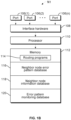
- FIGURE 1B is a simplified block diagram illustrating portions of example node N1.
- node N1 is implemented as node N1 of network 100.
- Nodes N2-N6 of FIGURE 1A may also be implemented similarly to FIGURE 1B .
- Node N1 includes ports 106(1) - 106(n), interface hardware 108, processor 110, and memory 112.
- Memory 112 includes routing programs 114, neighbor node error pattern database 116, neighbor node information database 118, and error pattern monitoring database 120.
- Data packets is received by node N1 at ports 106(1) - 106(n), processed by interface hardware 108 and processor 110, and then forwarded on to other nodes in network 100 from an appropriate port of port 106(1) - 106(n) based on a routing decision.
- Node N1 may be configured to use process switching and fast switching for routing data packets.
- processor 110 of node N1 determines a next hop node for a received data packet using routing programs 114, neighbor node information database 118, and neighbor node error pattern database 116.
- a next hop node for a received packet is determined based on cached information about a next hop node that was previously determined using process switching for a previously received data packet in the same packet session as the received data packet.
- Memory 112 may include a forwarding route cache that may store information that is used for determining the next hop node and the ports of 106(1) - 106(n) on which the data packet is sent on, for fast switching of data packets in the same session.
- information in the neighbor node information database 118 and neighbor node error pattern database 116 are used when determining next hop nodes for routing data packets in packet sessions.
- Error pattern monitoring database 120 is used to collect bit error pattern information that node N1 sends to neighbor nodes to be used by the neighbor nodes in routing data packets when node N1 is a potential next hop node of the neighbor nodes.
- FIGURE 2A is a simplified flow diagram illustrating operations performed for collaboratively sharing information in network node.
- FIGURE 2 may be explained with reference to FIGURES 1A and 1B .
- FIGURE 2A shows operations by which node N1 collaboratively shares its bit error pattern information en1 and other node information In1 with its neighbor nodes.
- each node NX of nodes N2 - N6 will similarly collaboratively share its bit error pattern information enx and other node information Inx with its neighbor nodes.
- node N1 sends node information In1 for node N1 to its neighbor nodes N2, N3, and N4.
- Processor 110 of node N1 may send node information In1 or updated node information In1 as necessary.
- node information may be sent when node N1 is powered up in network 100 for the first time, or after being shut down for maintenance and then powered up.
- the node information In1 may include addressing information that may be used by other nodes to reach node N1.
- the node information In1 may also include information about the error correction capabilities of node N1 and the error correction that node N1 is currently using.
- node N1 receives neighbor node information Inx (In2, In3, In4) from each of its neighbor nodes N2, N3, and N4.
- the node information Inx may include addressing information that may be used by other nodes to reach node N2, N3, or N4.
- the node information Inx may also include information about the error correction capabilities of nodes N2, N3, and N4, and the error correction that nodes N2, N3, and N4 are currently using.
- node N1 then stores/updates node information In2, In3, and In4 in neighbor node information database 118.
- node N1 determines a bit error pattern en1 for received data packets that are addressed to destination node N1 and processed at node N1.
- Processor 110 may determine bit error patterns for individual packets or groups of data packets over a time period and save bit error patterns in error pattern monitoring database 120.
- the time period may set to provide a desired of accuracy. For example, during network busy periods when many users are on the network, the time period may be set in seconds. In less busy time periods, the time period may be set in minutes or hours.
- Processor 110 may then determine a bit error pattern en1 for node N1, for example based on an average for all data packets received in the time period.
- the bit error pattern en1 may comprise information on average numbers of errors and location of bit errors in code words, including a measure of relative randomness to burstiness of bit errors at node N1.
- node N1 sends en1 to each of its neighbor nodes N2, N3, and N4.
- processor 110 retrieves any error patterns en2, en3, and en4, received from neighbor nodes N2, N3, and N4 and, at 214, updates neighbor node error pattern database 116.
- node N1 may receive the error patterns at time intervals, depending on how often each neighbor node updates and sends out its error patterns, and store the error patterns in a neighbor node error pattern queue as the error patterns are received.
- Processor 110 may then periodically check the queue at predetermined times for updated neighbor node error patterns. In the implementation of FIGURE 2 , the queue may be checked for updated neighbor node error patterns each time operation 212 is performed.
- node N1 determines whether it is time to update en1.
- Node N1 may be configured to update en1 at time intervals that provide a current and accurate error pattern en1 for use by the other nodes. For example, during network busy periods when many users are coming on and leaving the network the updating may be performed at time intervals of seconds. In less busy time periods the time period for updating may be set in minutes or hours. If it is determined to be time to update en1, the process moves to 208 and continues from 208 where processor 110 may continue to determine bit error patterns for individual packets or groups of data packets over a time period and save bit error patterns in error pattern monitoring database 120.
- Processor 110 may then determine an updated bit error pattern en1 for node N1 and send the updated en1 to nodes N2, N3, and N4 at operation 210 before moving to operation 212. If it is determined that it is not time to update en1 the process moves directly to 212 and continues from 212 where processor 110 retrieves any error patterns en2, en3, or en4 received from neighbor nodes N2, N3, and N4, and, at 214, updates neighbor node error pattern database 116 before returning to operation 216.
- Operations 208 - 216 of FIGURE 2A will be repeated by node N1 allowing node N1 to collaboratively share its bit error pattern information en1 with its neighbor nodes.
- Each of the other nodes N2 - N6 of network 100 will also repeat operations 208 - 216 to collaboratively share bit error pattern information with neighbor nodes. This collaborative sharing of bit error pattern information allows each node to determine next hop nodes in network 100 by making decisions with current information at the bit error level.
- node N1 may inform neighbor nodes N2, N3, and N4 and those nodes may update information In1 in their neighbor node information databases.
- Each of the neighbor nodes N2, N3, and N4 will also collaboratively share updated neighbor node information with node N1 if necessary when the node information changes.
- Node N1 may then update the appropriate neighbor node information, In2, In3, or In4, in neighbor node information database 118.
- a node may collaboratively share updated node information, for example, if the node is added to network 100, if the node is shut down for maintenance, if the node is powered up after maintenance, or if the node's relevant configurations, such as error correcting capabilities, are changed and/or updated.
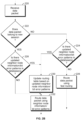
- FIGURE 2B is a flow diagram illustrating operations performed for routing data packets based on bit error pattern information in a network node.
- FIGURE 2B shows the operations that are performed in a node of network 100 when data packets are received for forwarding on to a next hop node.
- the operations of FIGURE 2B is performed at node N1 when data packets are received at node N1 for forwarding on to a next hop node of nodes N2, N3, or N4 on the way to a destination node in network 100 or in another network.
- processor 110 checks header information in the data packet header to determine if the received data packet belongs to a new session or if the data packet belongs to an ongoing session for which data packets have already been routed. Processor 110 may check this by determining if routing programs already have a next hop node stored in program routing tables for data packets having the source and destination addresses indicated in the packet header. If it is determined that the data packet belongs to a new packet session, i.e., the data packet is the first data packet received for a packet session, the process moves to operation 228.
- processor 110 determines if there is any updated neighbor node information in neighbor node information database 128, and/or any updated bit error pattern in neighbor node bit error pattern database 116.
- the updated neighbor node information and/or bit error pattern may be information collaboratively shared with node N1 through the process of FIGURE 2A by neighbor nodes N2, N3, and N4 as the process of FIGURE 2A is performed in the background over time.
- the updated neighbor node information and/or bit error pattern may be information received from neighbor nodes since the routing programs 114 last routed a data packet using the current routing tables in process routing. If there is any updated neighbor node information and/or any updated bit error pattern, the process moves to 230.
- processor 110 updates the routing tables of routing programs 114 based on the updated neighbor node information and/or bit error patterns.
- the routing tables may include information on connections and various alternative routing paths through the network for various destination nodes.
- the neighbor node information and neighbor node bit error patterns may be associated in the routing tables with next hop nodes of the various connections and various alternative routing paths to destination nodes.
- processor 110 determines a next hop node of nodes N2, N3, or N4, and the data packet is routed and sent to the next hop node.
- Processor 110 determines the next hop node by process routing that uses the neighbor node information and/or bit error patterns in the routing tables. In one implementation, processor 110 may determine that a destination address for the data packet is reached through one or more available next hop nodes. Then the next hop node is selected from the available next hop nodes based on a bit error pattern enx, where enx comprises a number of bit errors per code word that node NX is currently correcting.
- the latency and bit error pattern effects on a data packet session may be weighed relative to one another in the determination of the next hop node.
- latency considerations may be prioritized and given a higher weighting as compared to bit error considerations.
- the error patterns en2, en3, and en4 may each comprise a measure of relative randomness to burstiness of bit errors in code words received at nodes N2, N3, and N4, respectively.
- the measure of relative randomness to burstiness of bit errors may be utilized because certain error correcting codes are configured to be most effective depending on whether the bit errors the code is correcting are random or bursty. For example, a forward error correction code configured for maximum error correction capability when correcting bursty errors are used on the links between node N1 and nodes N2, N3, and N4.
- processor 110 determines if there is any updated neighbor information in neighbor node information database 128 and/or any updated bit error pattern in neighbor node bit error pattern database 116. Processor 110 may perform the operation at 224 in the same manner as was described for operation 228. If, at 224, it is determined that there is not any updated neighbor node information and/or bit error patterns, the process moves to 226. At 226 processor 110 performs fast routing and the data packet is routed to a next hop node for the session based on cached routing information that indicates the next hop node used for previous packets in the session.
- processor 110 updates the routing tables of routing programs 114 based on the updated neighbor node information and/or neighbor node bit error patterns. The updating of the routing tables may be performed in a similar manner as was described for operation 230 in the case when operation 230 is entered from operation 228.
- processor 110 determines a next hop node of nodes N2, N3, or N4, and the data packet is routed and sent to the next hop node.
- Processor 110 determines the next hop node by process routing and using the neighbor node information and/or bit error patterns in the routing tables for the determination.
- Processor 110 may determine the next hop node in a similar manner as was described previously for operation 230.
- processor 110 may compare the bit error pattern en2 to the error correction capability of node N2 that is included in In2. When the number of errors indicated in en2 approaches the bit error correction capability indicated in In2, processor 110 may make a determination to route to another node with a greater margin of difference between its number of errors and error correction capability. This routing may be used to preemptively prevent bit errors that cannot be corrected from occurring. For example, if eN2 indicates that node N2 is correcting 10 errors with an error correction capability of 11 errors and eN3 indicates that node N3 is correcting 12 errors with an error correction capability of 22 errors, node N1 may switch to routing its data traffic to node N3 over channel b as the next hop node instead of node N2.
- the data will then be routed to node N6 from node N3 over channel j.
- this routing may be done even though the number of bit errors at node N2 is less than the number of bit errors at node N3.
- an updated bit error pattern en2 given as a measure of relative randomness to burstiness of bit errors at node N2 may indicate that bit errors at node N2 are becoming increasingly random and neighbor node information In2 and In3 may indicate that node N3 has an error correcting capability better equipped to handle random bit errors than the error correcting capability of node N2.
- node N1 may switch to routing data traffic to node N3 instead of node N2.
- node N1 may use a bit error pattern, such as bit error pattern e2 from node N2, in making determinations as to how to adapt transmission parameters used for sending data traffic to neighbor nodes.
- Node N1 may increase or decrease the data rate, or change the error correction coding, for data packets sent to node N2 based on an error pattern e2 received from node N2.
- Packets of data traffic associated with a lower quality of service may be routed to a first neighbor node having a relatively higher number of bit errors indicated in that first neighbor node's error pattern. This may be used to maintain bandwidth to a second neighbor node, having a relatively lower number of bit errors indicated in that second neighbor node's error pattern, for packets of data traffic associated with a higher quality of service.
- network 100 may comprise an apparatus for managing routing within nodes N1 - N6.
- the apparatus may be a separate server device or is implemented in one of nodes N1 - N6.
- the apparatus may function to receive node information In1, In2, In3, In4, In5, and In6 from each of nodes N1, N2, N3, N4, N5, and N6.
- the node information may include addressing information that may be used by other nodes to reach a node.
- the node information may also include information about the error correction capabilities, and the error correction that the nodes are currently using.
- the apparatus may store/update the node information in a database as the node information is received and/or updated.
- the apparatus may also receive bit error patterns en1, en2, en3, en4, en5, and en6 from nodes N1, N2, N3, N4, N5, and N6 as the bit error patterns are determined by each node and updated during network operation. Based on the bit error patterns and the node information for each of the nodes, the apparatus may determine packet data traffic routing/management information and provide the information to nodes N1, N2, N3, N4, N5, and N6.
- the apparatus may also include a database including information associating types of data traffic to different quality of service values, and the packet data traffic routing/management information may include information to manage the nodes to take quality of service values into account when routing data packets.
- node information and/or node bit error pattern information may be collaboratively shared between nodes comprising devices transmitting and receiving on one or more wireless channels in a communications network.
- Devices that communicate with each other on the one or more channels may collaboratively share node information.
- Devices that receive on each of the one or more channels may determine bit error pattern information associated with each of the one or more channels at that receiving device. The devices may then collaboratively distribute the error pattern information associated with the one or more channels to devices transmitting on the one or more channels or devices that potentially will transmit on the one or more channels.
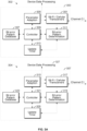
- FIGURE 3B is a diagram illustrating devices in an implementation of the aspects.
- FIGURE 3B shows a scenario in which device 302 is communicating with access point 304 on channel C1.
- Device 302 may comprise any type of mobile device or computing device that is configured to communicate with access point 304 and includes the functions of portion 303 of FIGURE 3A .
- Access point 304 may include the functions of portion 307 of FIGURE 3A .
- Device 302 and access point 304 may communicate with one another according to a wireless protocol such as one of the protocols specified in the IEEE 802.11 standards specifications.
- Device 302 may comprise a mobile cellular device and access point 304 may comprise a cellular base station operating according to a wide band code division multiple access (WCDMA) system protocol, long term evolution (LTE) system protocol, or other cellular protocol.
- WCDMA wide band code division multiple access
- LTE long term evolution
- FIGURE 3B device 302 is shown adapting its data transmission parameter set between time T1 and T2 according to bit error pattern e1 which is collaboratively shared from access point 304.
- FIGURE 3C is a flow diagram illustrating operations performed by the devices of FIGURE 3A and 3B in an implementation.
- FIGURE 3C is explained using device 302 and access point 304 of FIGURE 3A and 3B as device 1 and device 2, respectively, of FIGURE 3C .
- device 302 and access point 304 could be used as device 2 and device 1, respectively.
- the process begins at 306 when device 302 initiates operation on channel C1.
- the operation on channel C1 may include data traffic transmissions from device 302 to access point 304 at time T1 using Wi-Fi/cellular transceivers 301 and 317 having a transmission parameter set that comprises data rate DR1 and error correction coding 1 (ECC1).
- ECC1 error correction coding 1
- access point 304 receives the data transmissions at Wi-Fi/cellular transceivers 317 and sends the data to device data processing 327 for sending onward into the network.
- bit error pattern determination function 319 tracks bit errors and determines a bit error pattern e2 for transmissions to access point 304 on channel C1.
- bit error pattern determination function 319 may determine bit error pattern e2 using only transmissions received from device 302 on channel C1. In another implementation, bit error pattern determination function 319 may determine bit error pattern e2 using transmissions received from multiple devices on channel C1. The bit error pattern e2 may be determined over a time period or over a selected number of code words. In an implementation, bit error pattern e2 may comprise a parameter that indicates a number of bit errors per code word at access point 304. In another implementation, bit error pattern e2 may comprise a measure of relative randomness to burstiness, or a measure of burst length of bit errors in code words at access point 304.
- controller 321 controls bit error pattern determination function 319 to send the current bit error pattern e2 to device 302.
- Controller 309 receives the error pattern e2 through Wi-Fi/cellular transceivers 301 and stores error pattern e2 in bit error pattern database 307.
- parameter adaption function 305 of device 302 determines if bit error pattern e2 is greater than a threshold bit error pattern ET by comparing e2 to ET.
- ET may indicate a threshold amount of bit errors per code word for data transmissions from device 302. When bit errors in a code word are above the threshold amount of bit errors, it may be determined that e2 is greater than ET at 310.
- ET may indicate a threshold level of a measure of relative randomness to burstiness or a measure of burst length for bit errors of code words in data transmissions from device 302. When bit errors in a code word are above a threshold level of relative randomness to burstiness, it may be determined that e2 is greater than ET at 310.
- e2 may indicate both a threshold for a measure of randomness to burstiness for bit errors and a threshold for a number of bit errors per code word. In this case ET may be a combined threshold for a measure of relative randomness to burstiness for bit errors and a number of bit errors per code word.
- the determination at 310 may comprise determining whether both the measure of relative randomness to burstiness for bit errors and the threshold for a number of bit errors per code word were greater than their individual thresholds. If it is determined at 310 that bit error pattern e2 is not greater than ET, the process moves to 314. At 314, controller 321 of access point 304 determines if it is time to update error pattern e2. Update timer 325 may be checked for this determination. If it is determined it is not time to update e2, the process repeats the determination at 314 at time intervals until it is determined it is time to update e2. Update timer 325 may be set to indicate an update at selected time intervals.
- the time intervals set by update timer 325 for updating the error pattern information may be based, for example, on the degree of fading of the wireless channel used in a mobile network. The more severe the fading on channel C1 the more often the error pattern information needs to be updated.
- bit error pattern determination function 319 of access point 304 determines error pattern e2 and begins the process again using an updated error pattern e2.
- parameter adaption function 305 of device 302 determines that e2 is greater than ET, the process moves to 312.
- parameter adaption function 305 then adapts the parameter set used on channel C1 for data transmissions from Wi-Fi/cellular transceivers 301 to access point 304.
- parameter adaption function 305 may negotiate the adaption of the parameters with parameter adaption function 315 of access point 304. If device 302 and access point 304 disagree, access point 304 may control the rate adaption decision.
- the adaption of the transmission parameter set may comprise adapting the data rate DR1 and/or the error correction coding ECC1 to reduce the number of bit errors occurring.
- the adaption of transmission parameter set 1 may comprise adapting the data rate DR1 and/or the error correction coding ECC1 to account for an increase in randomness or bustiness of the bit errors.
- Data rate DR1 may be adapted by changing to a new data rate DR2 that is less than data rate DR1 to reduce the number of errors or the randomness/burstiness of the errors occurring.
- error correcting code ECC1 may be changed to an error correcting code ECC2 that is more robust and more capable of protecting against errors that are more random or more bursty than ECC1 is able to protect against.
- the data rate DR1 and/or the error correction coding ECC1 may be adapted to reduce the number of errors and the randomness/burstiness of the errors occurring.
- FIGURE 3B shows the updated parameter set being used by device 302 at time T2.
- This implementation may be used in combination with FIGURE 3B to dynamically adjust the data rate up or down based on error pattern e2 as channel conditions change.
- the implementation may also be used to dynamically adjust the error correction coding to be more stringent or less stringent based on e2 as channel conditions change.
- both device 302 and access point 304 may receive a bit error pattern from the other and adapt transmission parameters accordingly.
- access point 304 may send bit error pattern e2 associated with bit errors on channel C1 at access point 304
- device 302 may send bit error pattern e1 associated with bit errors on channel C1 at device 302.
- Device 302 and access point 304 may then adapt their transmission parameters on channel C1 based on the bit error patterns e2 and e1, respectively.
- the adaption of transmission parameters may include negotiation between device 302 and access point 304 to determine mutually agreed upon transmission parameters. In one example of negotiation, if device 302 and access point 304 disagree, access point 304 may control the rate adaption decision.
- access point 304 may also share bit error pattern e2 with other access points in the network, or provide bit error pattern e2 to a network database.
- the network database may be a database use by network administrators in making network configuration decisions based on bit error patterns occurring at network access points.
- FIGURE 3D is a flow diagram illustrating operations performed by the devices of FIGURES 3A and 3B in another implementation.
- FIGURE 3D is explained using device 302 and access point 304 of FIGURES 3A and 3B as device 1 and device 2, respectively, of FIGURE 3D .
- device 302 and access point 304 could be used as device 2 and device 1, respectively.
- the process of FIGURE 3D is basically the same as the process of FIGURE 3C except that operation 320 of FIGURE 3D uses an alternative method of comparison as compared to operation 310 of FIGURE 3C .
- parameter adaption function 305 of device 302 determines if bit error pattern e2 is within a margin of a maximum allowed threshold value Ecap by comparing Ecap with e2.
- Ecap may comprise a value indicating a maximum number of bit errors per code word that access point 304 is capable of correcting and it may be determined if Ecap - e2 is greater than the margin. If Ecap - e2 is greater than the margin the process may move to 324. If Ecap - e2 is not less than the margin the process may move to 322.
- device 302 may adapt the transmission parameter set that comprises data rate DR1 and error correction coding 1 (ECC1) based on the determination of 320.
- ECC1 error correction coding 1
- the margin used at operation 320 may be set to allow bit errors to be preemptively prevented from occurring.
- the margin may also be set differently for different applications on device 302.
- the margin may be set higher for applications that require higher quality transmissions with less bit errors so that the parameters are adapted before errors occur.
- the adaption of the parameter set may comprise adapting the data rate DR1 and/or the error correction coding ECC1 to reduce the number of bit errors occurring and increase Ecap - e2.
- the adaption of the parameter set may comprise adapting the data rate DR1 and/or the error correction coding ECC1 to account for an increase in randomness/burstiness of the bit errors and to increase the value of Ecap - e2.
- data rate DR1 may be adapted by changing to a new data rate DR2 that is less than data rate DR1 to reduce the number of errors or the randomness/burstiness of the errors occurring.
- error correcting code ECC1 may be changed to an error correcting code ECC2 that is more robust and capable of correcting a larger number of errors or errors that are more random or bursty than ECC1 is able to correct.
- ECC2 indicates both a measure of randomness to burstiness for bit errors and a number of bit errors per code word
- one or both of the data rate DR1 and/or the error correction coding ECC1 may be adapted to reduce the number of errors and the randomness of the errors occurring to increase the value of Ecap - e2.
- FIGURE 3B shows the updated parameter set being used by device 302 at time T2.
- the adaption of transmission parameter set 1 on channel 1 at 322 may also comprise changing to a new data rate that is faster than the current data rate and/or changing to an error correcting code ECC2 that is less robust and less capable of correcting a larger number of errors to increase data throughput when channel conditions are better. For example, this may be done when it is determined at 320 that Ecap - e2 is increasing in value indicating that fewer bit errors are occurring and/or the randomness or burstiness of the bit errors is decreasing. In this case, when fewer bit errors are occurring and/or randomness or burstiness of bit errors is low, it may be desirable to increase data throughput by adapting the data rate higher or using less stringent error correcting codes.
- This implementation may be used in combination with FIGURE 3C to dynamically adjust the data rate up and down based on error pattern e2 as the value of Ecap - e2 changes up and down.
- the implementation may also be used to dynamically adjust the error correction coding to be more stringent or less stringent as the value of Ecap - e2 changes up and down.
- device 302 may utilize bit error pattern e2 to make adapt transmission parameters by changing the channel on which device 302 transmits to access point 304. For example, if device 302 and access point 304 are capable of communicating on more than one channel, device 302 may switch to a channel other than channel C1 if e2 indicates unacceptable bit error patterns are occurring on channel C1.
- device 302 may adapt transmission parameters based on the bit error pattern and the type of the data traffic device 302 is transmitting to device 304.
- device 302 may determine a type of the data traffic using deep packet inspection.
- device 302 may include a database comprising information associating the type of the data traffic to a quality of service value.
- Device 302 may adapt transmission parameters based on the bit error pattern and the quality of service value associated with the type of the data traffic. For example, higher quality of service requirements related to latency may restrict how much the data rates are reduced, or lower quality of service requirements may restrict how much the data rate is increased, based on the bit error pattern.
- FIGURE 4A, 4B, and 4C are diagrams illustrating devices in a further implementation of the aspects.
- FIGURES 4A-4C show a sequence in which device 402 is shown collaboratively sharing bit error pattern information with device 404.
- FIGURE 4D is a flow diagram illustrating operations performed by the devices in FIGURES 4A-4C.
- FIGURE 4D may be explained with reference to FIGURES 4A-4C using device 402 as device 1, access point 406 as device 2, and device 404 as device 3.
- the process of FIGURE 4D begins at 408 when device 402 begins operation on channel C1 as shown in FIGURE 4A .
- the operation on channel 1 may include data traffic transmissions from device 402 to access point 404 at time T1.
- access point 406 receives the data transmissions and sends the data transmission onward toward a destination in the network infrastructure.
- access point 406 also tracks bit errors and determines a bit error pattern e2 for transmission from device 402 on channel C1.
- the bit error pattern e2 may be determined over a time period or over a selected number of code words.
- bit error pattern e2 may comprise a parameter that indicates a number of bit errors per code word. In another implementation, bit error pattern e2 may comprise a measure of relative randomness to burstiness of bit errors in code words.
- access point 406 sends error pattern e2 to device 402.
- device 402 determines if a query for bit error pattern information has been received from another device.
- device 402 may monitor a short range interface such as Bluetooth or Wi-Fi direct to detect and receive queries for bit error pattern information from other devices operating in its vicinity. For example, other devices moving into the coverage area of access point 406 may send out these queries to attempt to gather information on access points near their location. If no query has been received the process moves to 416.
- access point 406 determines if it is time to update e2. If it is time to update e2, the process returns to 410. If it is not time to update e2, the process moves to 412 where device 402 again determines if a query for bit error pattern information has been received from another device. Operations 412 and 416 are then repeated until access point 106 determines that it is time to update e2 and the process moves to operation 410.
- device 402 may determine the device that sent the query, which in this example is device 404, and send e2 to device 404 as shown in FIGURE 4B at time T2.
- device 404 may adapt its initial transmission parameters for data transmissions to access point 406 on channel C1 based on e2, and, at 422, as shown in FIGURE 4C at time T3, initiate operation on channel C1 using the transmission parameters as adapted.
- device 402 may be located in the coverage area of multiple access points and may receive error pattern information from multiple devices, each communicating with a different access point of the multiple access points using the process of FIGURE 4D . Device 402 may then select an access point of available access points based on the error pattern information received from the multiple access points. Also, in another implementation, device 402 may receive error pattern information from multiple devices, each communicating with access point 406 on a different channel using the process of FIGURE 4D . Device 402 may then select a channel on which to communicate with access point 406 based on the error pattern information received from the multiple access points.
- FIGURE 5 is a simplified block diagram of a device 500.
- the functions shown in FIGURE 3A is implemented on a device such as device 500.
- Device 500 may include a processor 506, memory 508, user interfaces 520, short range transceivers (TRXS) 504, and Wi-Fi/cellular transceiver (TRXS) 502.
- TRXS short range transceivers
- TRXS Wi-Fi/cellular transceiver
- not all the functions shown in FIGURE 5 will be needed.
- Memory 508 may be implemented as any type of computer readable storage media, including non-volatile and volatile memory.
- Memory 508 is shown as including code comprising device operating system (OS) 510, device applications 512, bit error pattern determination programs 514 and parameter adaption control programs 516.
- Processor 506 may comprise one or more processors, or other control circuitry, or any combination of processors and control circuitry.
- the bit error pattern determination programs 514 may provide the functions described for bit error determination functions 311 or 319 shown in FIGURE 3A . When executed, the bit error pattern determination programs 514 may cause processor 506 to control device 500 to perform processes to monitor received data and determine error patterns for the received data. The error patterns may then be collaboratively shared with other devices according to the disclosed implementations.
- Parameter adaption control programs 516 may provide the functions described for parameter adaption functions 305 or 315 shown in FIGURE 3A . When executed, parameter adaption control programs 516 may cause processor 506 to control device 500 to receive collaboratively shared error pattern information and use the error pattern information to adapt transmission parameters based on the error pattern information according to the implementations.
- device 500 may be any type of device that may be configured to communicate with a network or other device.
- Device 500 may be implemented in a smart phone, a tablet computer, a desktop computer, laptop computer device, gaming devices, media devices, smart televisions, multimedia cable/television boxes, smart phone accessory devices, tablet accessory devices, or personal digital assistants (PDAs).
- Device 500 may also comprise an access point, base station or other infrastructure equipment of a network that communicates with other devices in the network.
- device 500 may operate according to a timed division half-duplex communications standard. For example, device 500 may operate using half-duplex channels specified in the IEEE 802.11 Wi-Fi standards.
- processor-executable code or instructions stored on memory may comprise one or more computer readable storage media (e.g., tangible non-transitory computer-readable storage media such as memory 508).
- computer readable storage media e.g., tangible non-transitory computer-readable storage media such as memory 508.
- non-transitory computer-readable media include the media for storing of data, code and program instructions, such as memory 508, and do not include portions of the media for storing transitory propagated or modulated data communication signals.
- While implementations have been disclosed and described as having functions implemented on particular wireless devices operating in a network, one or more of the described functions for the devices may be implemented on a different one of the devices than shown in the figures, or on different types of equipment operating in different systems.
- processors or processing units controllers, and memory including instructions and code
- the functions and processes of the aspects may be implemented and performed using any appropriate functional blocks, type of processor, circuitry or combinations of processors and/or circuitry and code.
- This may include, at least in part, one or more hardware logic components.
- illustrative types of hardware logic components include field programmable gate arrays (FPGAs), application specific integrated circuits (ASICs), application specific standard products (ASSPs), system-on-a-chip systems (SOCs), complex programmable logic devices (CPLDs), etc.
- FPGAs field programmable gate arrays
- ASICs application specific integrated circuits
- ASSPs application specific standard products
- SOCs system-on-a-chip systems
- CPLDs complex programmable logic devices
Landscapes
- Engineering & Computer Science (AREA)
- Signal Processing (AREA)
- Computer Networks & Wireless Communication (AREA)
- Quality & Reliability (AREA)
- Computer Security & Cryptography (AREA)
- Mobile Radio Communication Systems (AREA)
- Data Exchanges In Wide-Area Networks (AREA)
- Detection And Prevention Of Errors In Transmission (AREA)
Claims (4)
- Premier noeud, N1, configuré pour fonctionner dans un réseau comprenant une pluralité de noeuds configurés pour acheminer un paquet de données d'un noeud source à un noeud de destination, la pluralité de noeuds comprenant un noeud source, un noeud de destination et une pluralité de noeuds intermédiaires configurés pour acheminer le paquet de données du noeud source vers le noeud de destination, la pluralité de noeuds intermédiaires comprenant le premier noeud et une pluralité de seconds noeuds, le premier noeud comprenant :un ou plusieurs processeurs (110) ; etune mémoire (112) en communication avec le ou les processeurs, la mémoire comprenant des instructions exécutables (116, 118, 120) qui, lorsqu'elles sont exécutées, amènent le ou les processeurs à contrôler le premier noeud afin de :recevoir une pluralité de schémas d'erreurs binaires (212) associés à une pluralité de canaux établis entre le premier noeud et la pluralité de seconds noeuds, respectivement ;sur la base de la pluralité de schémas d'erreurs binaires, sélectionner un noeud de la pluralité de seconds noeuds en guise de noeud de saut suivant ; etlors de la réception du paquet de données du noeud source ou de l'un de la pluralité de seconds noeuds, acheminer l'au moins un paquet de données reçu vers le second noeud sélectionné en guise de noeud de saut suivant (232) ;dans lequel la pluralité de schémas d'erreurs binaires comprend au moins l'une parmi :une pluralité de mesures du caractère aléatoire d'éclatement d'erreurs binaires associées à la pluralité de canaux, respectivement, et dans lequel le caractère aléatoire d'éclatement relatif est déterminé en comparant le schéma d'erreur binaire de noeuds respectifs et en sélectionnant le saut suivant en fonction du noeud respectif ayant la moindre mesure de caractère aléatoire d'éclatement relatif ;une pluralité de mesures de caractère aléatoire d'erreur binaire associées à la pluralité de canaux, respectivement, et dans lequel le premier noeud sélectionne le noeud de saut suivant sur la base des mesures de caractère aléatoire d'erreur binaire ; etune pluralité de mesures d'éclatement d'erreur binaire associées à la pluralité de canaux, respectivement, et dans lequel le premier noeud sélectionne le noeud de saut suivant sur la base des mesures d'éclatement d'erreur binaire ;dans lequel chaque schéma d'erreur binaire comprend un nombre d'erreurs binaires et un emplacement d'erreurs binaires dans un mot-code.
- Premier noeud selon la revendication 1, dans lequel les instructions amènent en outre le ou les processeurs à contrôler le premier noeud pour déterminer le noeud de saut suivant en fonction de la pluralité de schémas d'erreurs binaires et d'un type de trafic de l'au moins un paquet de données.
- Premier noeud selon la revendication 2, dans lequel les instructions amènent en outre le ou les processeurs à contrôler le premier noeud pour déterminer le type de trafic de l'au moins un paquet de données à l'aide d'une inspection approfondie des paquets.
- Premier noeud selon la revendication 2, dans lequel la mémoire comprend en outre une base de données incluant des informations associant le type de trafic de l'au moins un paquet de données à une valeur de qualité de service, et les instructions amènent en outre le ou les processeurs à contrôler le premier noeud pour déterminer le noeud de saut suivant en fonction de la pluralité de schémas d'erreurs binaires et de la valeur de qualité de service associée au type de trafic de l'au moins un paquet de données.
Priority Applications (1)
| Application Number | Priority Date | Filing Date | Title |
|---|---|---|---|
| EP19209026.4A EP3644536B1 (fr) | 2016-10-10 | 2017-10-03 | Communications collaboratives |
Applications Claiming Priority (2)
| Application Number | Priority Date | Filing Date | Title |
|---|---|---|---|
| US15/289,954 US10492084B2 (en) | 2016-10-10 | 2016-10-10 | Collaborative communications |
| PCT/US2017/054810 WO2018071220A1 (fr) | 2016-10-10 | 2017-10-03 | Communications collaboratives |
Related Child Applications (2)
| Application Number | Title | Priority Date | Filing Date |
|---|---|---|---|
| EP19209026.4A Division-Into EP3644536B1 (fr) | 2016-10-10 | 2017-10-03 | Communications collaboratives |
| EP19209026.4A Division EP3644536B1 (fr) | 2016-10-10 | 2017-10-03 | Communications collaboratives |
Publications (2)
| Publication Number | Publication Date |
|---|---|
| EP3523903A1 EP3523903A1 (fr) | 2019-08-14 |
| EP3523903B1 true EP3523903B1 (fr) | 2024-12-18 |
Family
ID=60120182
Family Applications (2)
| Application Number | Title | Priority Date | Filing Date |
|---|---|---|---|
| EP19209026.4A Active EP3644536B1 (fr) | 2016-10-10 | 2017-10-03 | Communications collaboratives |
| EP17785124.3A Active EP3523903B1 (fr) | 2016-10-10 | 2017-10-03 | Communications collaboratives |
Family Applications Before (1)
| Application Number | Title | Priority Date | Filing Date |
|---|---|---|---|
| EP19209026.4A Active EP3644536B1 (fr) | 2016-10-10 | 2017-10-03 | Communications collaboratives |
Country Status (4)
| Country | Link |
|---|---|
| US (2) | US10492084B2 (fr) |
| EP (2) | EP3644536B1 (fr) |
| CN (2) | CN109804581A (fr) |
| WO (1) | WO2018071220A1 (fr) |
Families Citing this family (12)
| Publication number | Priority date | Publication date | Assignee | Title |
|---|---|---|---|---|
| CN108353321B (zh) * | 2016-11-04 | 2021-02-09 | 华为技术有限公司 | 一种网络热点控制的方法以及相关设备 |
| US10602551B2 (en) | 2018-06-27 | 2020-03-24 | Charter Communications Operating, Llc | Methods and apparatus for testing alternative wireless connections and selecting a wireless connection |
| US11019545B2 (en) | 2018-06-27 | 2021-05-25 | Charter Communications Operating, Llc | Handover methods and apparatus |
| US10856348B2 (en) * | 2018-06-27 | 2020-12-01 | Charter Communications Operating, Llc | Methods and apparatus for determining a number of connections to use at a given time and/or the level of error correcting coding to use based on connection scores |
| US10911284B1 (en) | 2019-07-16 | 2021-02-02 | Microsoft Technology Licensing, Llc | Intelligent optimization of communication systems utilizing error correction |
| US11172455B2 (en) | 2019-07-16 | 2021-11-09 | Microsoft Technology Licensing, Llc | Peak to average power output reduction of RF systems utilizing error correction |
| US11075656B2 (en) | 2019-07-16 | 2021-07-27 | Microsoft Technology Licensing, Llc | Bit error reduction of communication systems using error correction |
| US11063696B2 (en) | 2019-07-16 | 2021-07-13 | Microsoft Technology Licensing, Llc | Increasing average power levels to reduce peak-to-average power levels using error correction codes |
| US11086719B2 (en) | 2019-07-16 | 2021-08-10 | Microsoft Technology Licensing, Llc | Use of error correction codes to prevent errors in neighboring storage |
| US11044044B2 (en) | 2019-07-16 | 2021-06-22 | Microsoft Technology Licensing, Llc | Peak to average power ratio reduction of optical systems utilizing error correction |
| US11031961B2 (en) | 2019-07-16 | 2021-06-08 | Microsoft Technology Licensing, Llc | Smart symbol changes for optimization of communications using error correction |
| US10911141B1 (en) | 2019-07-30 | 2021-02-02 | Microsoft Technology Licensing, Llc | Dynamically selecting a channel model for optical communications |
Family Cites Families (37)
| Publication number | Priority date | Publication date | Assignee | Title |
|---|---|---|---|---|
| DE3733278A1 (de) * | 1987-09-29 | 1989-04-13 | Siemens Ag | Messverfahren zur stoerungsanalyse digitaler uebertragungswege und messeinrichtung zur durchfuehrung des messverfahrens |
| US6148423A (en) * | 1992-07-22 | 2000-11-14 | Alcatel Cit | Signal transmission performance optimization device in a system for transmitting digital data, especially on an optical link |
| US6411946B1 (en) | 1998-08-28 | 2002-06-25 | General Instrument Corporation | Route optimization and traffic management in an ATM network using neural computing |
| US6647208B1 (en) | 1999-03-18 | 2003-11-11 | Massachusetts Institute Of Technology | Hybrid electronic/optical switch system |
| US7151769B2 (en) * | 2001-03-22 | 2006-12-19 | Meshnetworks, Inc. | Prioritized-routing for an ad-hoc, peer-to-peer, mobile radio access system based on battery-power levels and type of service |
| JP4037640B2 (ja) | 2001-11-15 | 2008-01-23 | 日本電気株式会社 | 無線端末 |
| US6915463B2 (en) | 2001-12-26 | 2005-07-05 | Richard Charles Vieregge | System and method for performing pre-emptive protection switching |
| US7257086B2 (en) | 2002-08-27 | 2007-08-14 | Terabeam Corporation | Method and system for effectuating network routing over primary and backup channels |
| JP4071117B2 (ja) * | 2003-01-23 | 2008-04-02 | シャープ株式会社 | 送受信回路及び送受信方法並びに送受信装置 |
| US10476619B2 (en) | 2003-04-23 | 2019-11-12 | Apple Inc. | Routing quality-of-service traffic in a wireless system |
| US7573856B2 (en) | 2003-11-25 | 2009-08-11 | Telefonaktiebolaget Lm Ericsson (Publ) | Power-based rate adaptation of wireless communication channels |
| ES2409334T3 (es) * | 2003-12-23 | 2013-06-26 | Telefonaktiebolaget Lm Ericsson (Publ) | Ad hoc predictivo |
| AU2003290491A1 (en) | 2003-12-23 | 2005-07-14 | Telefonaktiebolaget Lm Ericsson (Publ) | Method and system for routing traffic in ad hoc networks |
| US7487433B2 (en) | 2005-06-10 | 2009-02-03 | Microsoft Corporation | Exception handling in content based routing solutions |
| US8205146B2 (en) | 2005-07-21 | 2012-06-19 | Hewlett-Packard Development Company, L.P. | Persistent error detection in digital memory |
| US8611275B2 (en) * | 2005-08-17 | 2013-12-17 | Intel Corporation | Methods and apparatus for providing an integrated multi-hop routing and cooperative diversity system |
| US20070086354A1 (en) | 2005-10-17 | 2007-04-19 | Erickson Bruce A | Method and apparatus for performing a bit error rate test, and for configuring the receiving or transmitting end of a communication link |
| US20070091928A1 (en) | 2005-10-21 | 2007-04-26 | Wee Susie J | Serial and parallel processing of data using information about the data and information about a streaming network |
| US8381047B2 (en) | 2005-11-30 | 2013-02-19 | Microsoft Corporation | Predicting degradation of a communication channel below a threshold based on data transmission errors |
| BRPI0712598B1 (pt) * | 2006-05-19 | 2019-10-29 | Panasonic Corp | dispositivo de transmissão de rádio e método de transmissão de rádio |
| US8295189B2 (en) | 2007-05-11 | 2012-10-23 | Microsoft Corporation | Interference detection |
| US7965671B2 (en) | 2007-10-01 | 2011-06-21 | Powerwave Cognition, Inc. | Dynamic channel sharing using bandwidth metrics |
| MX2010010913A (es) * | 2008-04-04 | 2010-12-21 | Powerwave Cognition Inc | Metodos y sistemas para una internet movil de banda ancha, enrutable. |
| US20110164527A1 (en) | 2008-04-04 | 2011-07-07 | Mishra Rajesh K | Enhanced wireless ad hoc communication techniques |
| JP5094593B2 (ja) * | 2008-06-27 | 2012-12-12 | キヤノン株式会社 | 送信装置、受信装置、及び方法、プログラム |
| EP2184880A1 (fr) | 2008-11-07 | 2010-05-12 | Thomson Licensing | Procédé d'adaptation de débit de données pour communication par multidiffusion |
| CN101925088B (zh) * | 2009-06-12 | 2015-02-18 | 株式会社Ntt都科摩 | 一种基于用户体验质量测量的编码方法、终端和系统 |
| US9106563B2 (en) * | 2009-10-07 | 2015-08-11 | Wichorus, Inc. | Method and apparatus for switching communications traffic in a communications network |
| CN101808384B (zh) * | 2010-03-25 | 2012-07-25 | 中国电信股份有限公司 | 无线传感器网络、路由选择方法及节点设备 |
| CN102647333B (zh) * | 2011-02-21 | 2016-03-30 | 中国移动通信集团公司 | 分布式基站系统下基带处理设备之间的通信方法和装置 |
| CN102548034B (zh) * | 2011-12-26 | 2015-04-08 | 哈尔滨工业大学 | 重大钢混结构用无线自集能腐蚀监测传感器网络 |
| CN102457914B (zh) * | 2012-01-11 | 2017-11-10 | 中兴通讯股份有限公司 | 上行数据及上行调度信息的传输方法、装置 |
| JP5853810B2 (ja) | 2012-03-26 | 2016-02-09 | 富士通株式会社 | 伝送装置、及び伝送特性調整方法 |
| DE102012104880A1 (de) * | 2012-06-05 | 2013-12-05 | Fujitsu Technology Solutions Intellectual Property Gmbh | Verfahren zur Parametrisierung einer Signalanpassungseinheit sowie Datenübertragungssystem mit zumindest zwei elektronischen Geräten |
| CN104521193B (zh) * | 2013-07-08 | 2017-09-05 | 华为技术有限公司 | 一种误码率检测的方法及网络设备 |
| WO2016057482A1 (fr) | 2014-10-06 | 2016-04-14 | Vid Scale, Inc. | Adaptation de paramètres de communication à des états de liaisons, à des types de trafic et/ou à des priorités |
| US9483340B1 (en) | 2015-09-09 | 2016-11-01 | Juniper Networks, Inc. | Estimating bit error rate |
-
2016
- 2016-10-10 US US15/289,954 patent/US10492084B2/en active Active
-
2017
- 2017-10-03 CN CN201780062603.6A patent/CN109804581A/zh active Pending
- 2017-10-03 WO PCT/US2017/054810 patent/WO2018071220A1/fr not_active Ceased
- 2017-10-03 CN CN202410304164.7A patent/CN118200944A/zh active Pending
- 2017-10-03 EP EP19209026.4A patent/EP3644536B1/fr active Active
- 2017-10-03 EP EP17785124.3A patent/EP3523903B1/fr active Active
-
2018
- 2018-10-12 US US16/159,562 patent/US10785663B2/en active Active
Also Published As
| Publication number | Publication date |
|---|---|
| EP3523903A1 (fr) | 2019-08-14 |
| CN109804581A (zh) | 2019-05-24 |
| CN118200944A (zh) | 2024-06-14 |
| EP3644536A2 (fr) | 2020-04-29 |
| US20190045381A1 (en) | 2019-02-07 |
| US10785663B2 (en) | 2020-09-22 |
| US10492084B2 (en) | 2019-11-26 |
| EP3644536A3 (fr) | 2020-08-19 |
| EP3644536B1 (fr) | 2026-01-07 |
| US20180103382A1 (en) | 2018-04-12 |
| WO2018071220A1 (fr) | 2018-04-19 |
Similar Documents
| Publication | Publication Date | Title |
|---|---|---|
| EP3523903B1 (fr) | Communications collaboratives | |
| US9842013B2 (en) | Dynamic adaptive approach for failure detection of node in a cluster | |
| EP3090513B1 (fr) | Configuration d'ingénierie de trafic adaptative | |
| US20150063144A1 (en) | Method and apparatus for software defined flow control in wireless systems | |
| US20140341078A1 (en) | Reduction of message and computational overhead in networks | |
| US20170063699A1 (en) | Method and apparatus for configuring multi-paths using segment list | |
| JP2016541198A (ja) | ソフトウェア定義ネットワーキングにおける、トラフィックエンジニアリングのためのフレームワーク | |
| US10230648B2 (en) | Method and system for rate adaptation for data traffic | |
| TWI531186B (zh) | 多重介面網路裝置與網路封包傳送選擇方法 | |
| US11323310B2 (en) | Method, device, and system for providing hot reservation for in-line deployed network functions with multiple network interfaces | |
| GB2578415A (en) | Methods and systems for transmitting information packets through tunnel groups at a network node | |
| CN105591960A (zh) | 调整隧道负载的方法和设备 | |
| US20250015925A1 (en) | Multi-channel data transmission method and receiving method, transmission end, and receiving end | |
| US9537764B2 (en) | Communication apparatus, control apparatus, communication system, communication method, method for controlling communication apparatus, and program | |
| US20180263070A1 (en) | Data transmission method and apparatus | |
| CN113676408A (zh) | 虚拟专用网络的选路方法、系统、设备及存储介质 | |
| US20140307581A1 (en) | Device and method of communicating, and computer readable medium for communicating | |
| JP6801075B2 (ja) | データ・パケットのパス情報を得る方法及びデバイス | |
| US10432502B2 (en) | Method and apparatus for overlap-resistant dynamic routing | |
| JP5780601B2 (ja) | データ転送方法および無線ネットワークシステム | |
| KR102450152B1 (ko) | 트래픽 사이즈 산출 방법 | |
| EP3518578B1 (fr) | Gestionnaire de données permettant de distribuer des données d'un flux de données d'un équipement utilisateur par l'intermédiaire de multiples liaisons de réseau local sans fil | |
| US10165598B2 (en) | Wireless medium clearing | |
| US8792379B1 (en) | Determining link capacity | |
| TW201624973A (zh) | 軟體定義網路的控制方法、控制器和封包處理方法 |
Legal Events
| Date | Code | Title | Description |
|---|---|---|---|
| STAA | Information on the status of an ep patent application or granted ep patent |
Free format text: STATUS: UNKNOWN |
|
| STAA | Information on the status of an ep patent application or granted ep patent |
Free format text: STATUS: THE INTERNATIONAL PUBLICATION HAS BEEN MADE |
|
| PUAI | Public reference made under article 153(3) epc to a published international application that has entered the european phase |
Free format text: ORIGINAL CODE: 0009012 |
|
| STAA | Information on the status of an ep patent application or granted ep patent |
Free format text: STATUS: REQUEST FOR EXAMINATION WAS MADE |
|
| 17P | Request for examination filed |
Effective date: 20190311 |
|
| AK | Designated contracting states |
Kind code of ref document: A1 Designated state(s): AL AT BE BG CH CY CZ DE DK EE ES FI FR GB GR HR HU IE IS IT LI LT LU LV MC MK MT NL NO PL PT RO RS SE SI SK SM TR |
|
| AX | Request for extension of the european patent |
Extension state: BA ME |
|
| DAV | Request for validation of the european patent (deleted) | ||
| DAX | Request for extension of the european patent (deleted) | ||
| STAA | Information on the status of an ep patent application or granted ep patent |
Free format text: STATUS: EXAMINATION IS IN PROGRESS |
|
| 17Q | First examination report despatched |
Effective date: 20210311 |
|
| RAP3 | Party data changed (applicant data changed or rights of an application transferred) |
Owner name: MICROSOFT TECHNOLOGY LICENSING, LLC |
|
| RIC1 | Information provided on ipc code assigned before grant |
Ipc: H04W 40/00 20090101ALI20240717BHEP Ipc: H04L 1/00 20060101AFI20240717BHEP |
|
| GRAP | Despatch of communication of intention to grant a patent |
Free format text: ORIGINAL CODE: EPIDOSNIGR1 |
|
| STAA | Information on the status of an ep patent application or granted ep patent |
Free format text: STATUS: GRANT OF PATENT IS INTENDED |
|
| GRAJ | Information related to disapproval of communication of intention to grant by the applicant or resumption of examination proceedings by the epo deleted |
Free format text: ORIGINAL CODE: EPIDOSDIGR1 |
|
| STAA | Information on the status of an ep patent application or granted ep patent |
Free format text: STATUS: EXAMINATION IS IN PROGRESS |
|
| GRAP | Despatch of communication of intention to grant a patent |
Free format text: ORIGINAL CODE: EPIDOSNIGR1 |
|
| STAA | Information on the status of an ep patent application or granted ep patent |
Free format text: STATUS: GRANT OF PATENT IS INTENDED |
|
| INTG | Intention to grant announced |
Effective date: 20240827 |
|
| INTC | Intention to grant announced (deleted) | ||
| INTG | Intention to grant announced |
Effective date: 20240912 |
|
| GRAS | Grant fee paid |
Free format text: ORIGINAL CODE: EPIDOSNIGR3 |
|
| P01 | Opt-out of the competence of the unified patent court (upc) registered |
Free format text: CASE NUMBER: APP_55474/2024 Effective date: 20241009 |
|
| GRAA | (expected) grant |
Free format text: ORIGINAL CODE: 0009210 |
|
| STAA | Information on the status of an ep patent application or granted ep patent |
Free format text: STATUS: THE PATENT HAS BEEN GRANTED |
|
| AK | Designated contracting states |
Kind code of ref document: B1 Designated state(s): AL AT BE BG CH CY CZ DE DK EE ES FI FR GB GR HR HU IE IS IT LI LT LU LV MC MK MT NL NO PL PT RO RS SE SI SK SM TR |
|
| REG | Reference to a national code |
Ref country code: GB Ref legal event code: FG4D |
|
| REG | Reference to a national code |
Ref country code: CH Ref legal event code: EP |
|
| REG | Reference to a national code |
Ref country code: DE Ref legal event code: R096 Ref document number: 602017086838 Country of ref document: DE |
|
| REG | Reference to a national code |
Ref country code: IE Ref legal event code: FG4D |
|
| REG | Reference to a national code |
Ref country code: LT Ref legal event code: MG9D |
|
| PG25 | Lapsed in a contracting state [announced via postgrant information from national office to epo] |
Ref country code: HR Free format text: LAPSE BECAUSE OF FAILURE TO SUBMIT A TRANSLATION OF THE DESCRIPTION OR TO PAY THE FEE WITHIN THE PRESCRIBED TIME-LIMIT Effective date: 20241218 |
|
| PG25 | Lapsed in a contracting state [announced via postgrant information from national office to epo] |
Ref country code: FI Free format text: LAPSE BECAUSE OF FAILURE TO SUBMIT A TRANSLATION OF THE DESCRIPTION OR TO PAY THE FEE WITHIN THE PRESCRIBED TIME-LIMIT Effective date: 20241218 |
|
| PG25 | Lapsed in a contracting state [announced via postgrant information from national office to epo] |
Ref country code: BG Free format text: LAPSE BECAUSE OF FAILURE TO SUBMIT A TRANSLATION OF THE DESCRIPTION OR TO PAY THE FEE WITHIN THE PRESCRIBED TIME-LIMIT Effective date: 20241218 |
|
| PG25 | Lapsed in a contracting state [announced via postgrant information from national office to epo] |
Ref country code: NO Free format text: LAPSE BECAUSE OF FAILURE TO SUBMIT A TRANSLATION OF THE DESCRIPTION OR TO PAY THE FEE WITHIN THE PRESCRIBED TIME-LIMIT Effective date: 20250318 |
|
| REG | Reference to a national code |
Ref country code: NL Ref legal event code: MP Effective date: 20241218 |
|
| PG25 | Lapsed in a contracting state [announced via postgrant information from national office to epo] |
Ref country code: LV Free format text: LAPSE BECAUSE OF FAILURE TO SUBMIT A TRANSLATION OF THE DESCRIPTION OR TO PAY THE FEE WITHIN THE PRESCRIBED TIME-LIMIT Effective date: 20241218 Ref country code: GR Free format text: LAPSE BECAUSE OF FAILURE TO SUBMIT A TRANSLATION OF THE DESCRIPTION OR TO PAY THE FEE WITHIN THE PRESCRIBED TIME-LIMIT Effective date: 20250319 |
|
| PG25 | Lapsed in a contracting state [announced via postgrant information from national office to epo] |
Ref country code: RS Free format text: LAPSE BECAUSE OF FAILURE TO SUBMIT A TRANSLATION OF THE DESCRIPTION OR TO PAY THE FEE WITHIN THE PRESCRIBED TIME-LIMIT Effective date: 20250318 |
|
| PG25 | Lapsed in a contracting state [announced via postgrant information from national office to epo] |
Ref country code: NL Free format text: LAPSE BECAUSE OF FAILURE TO SUBMIT A TRANSLATION OF THE DESCRIPTION OR TO PAY THE FEE WITHIN THE PRESCRIBED TIME-LIMIT Effective date: 20241218 |
|
| REG | Reference to a national code |
Ref country code: AT Ref legal event code: MK05 Ref document number: 1753104 Country of ref document: AT Kind code of ref document: T Effective date: 20241218 |
|
| PG25 | Lapsed in a contracting state [announced via postgrant information from national office to epo] |
Ref country code: SM Free format text: LAPSE BECAUSE OF FAILURE TO SUBMIT A TRANSLATION OF THE DESCRIPTION OR TO PAY THE FEE WITHIN THE PRESCRIBED TIME-LIMIT Effective date: 20241218 |
|
| PG25 | Lapsed in a contracting state [announced via postgrant information from national office to epo] |
Ref country code: PL Free format text: LAPSE BECAUSE OF FAILURE TO SUBMIT A TRANSLATION OF THE DESCRIPTION OR TO PAY THE FEE WITHIN THE PRESCRIBED TIME-LIMIT Effective date: 20241218 |
|
| PG25 | Lapsed in a contracting state [announced via postgrant information from national office to epo] |
Ref country code: ES Free format text: LAPSE BECAUSE OF FAILURE TO SUBMIT A TRANSLATION OF THE DESCRIPTION OR TO PAY THE FEE WITHIN THE PRESCRIBED TIME-LIMIT Effective date: 20241218 |
|
| PG25 | Lapsed in a contracting state [announced via postgrant information from national office to epo] |
Ref country code: IS Free format text: LAPSE BECAUSE OF FAILURE TO SUBMIT A TRANSLATION OF THE DESCRIPTION OR TO PAY THE FEE WITHIN THE PRESCRIBED TIME-LIMIT Effective date: 20250418 |
|
| PG25 | Lapsed in a contracting state [announced via postgrant information from national office to epo] |
Ref country code: PT Free format text: LAPSE BECAUSE OF FAILURE TO SUBMIT A TRANSLATION OF THE DESCRIPTION OR TO PAY THE FEE WITHIN THE PRESCRIBED TIME-LIMIT Effective date: 20250421 |
|
| PG25 | Lapsed in a contracting state [announced via postgrant information from national office to epo] |
Ref country code: EE Free format text: LAPSE BECAUSE OF FAILURE TO SUBMIT A TRANSLATION OF THE DESCRIPTION OR TO PAY THE FEE WITHIN THE PRESCRIBED TIME-LIMIT Effective date: 20241218 |
|
| PG25 | Lapsed in a contracting state [announced via postgrant information from national office to epo] |
Ref country code: RO Free format text: LAPSE BECAUSE OF FAILURE TO SUBMIT A TRANSLATION OF THE DESCRIPTION OR TO PAY THE FEE WITHIN THE PRESCRIBED TIME-LIMIT Effective date: 20241218 Ref country code: AT Free format text: LAPSE BECAUSE OF FAILURE TO SUBMIT A TRANSLATION OF THE DESCRIPTION OR TO PAY THE FEE WITHIN THE PRESCRIBED TIME-LIMIT Effective date: 20241218 |
|
| PG25 | Lapsed in a contracting state [announced via postgrant information from national office to epo] |
Ref country code: SK Free format text: LAPSE BECAUSE OF FAILURE TO SUBMIT A TRANSLATION OF THE DESCRIPTION OR TO PAY THE FEE WITHIN THE PRESCRIBED TIME-LIMIT Effective date: 20241218 |
|
| PG25 | Lapsed in a contracting state [announced via postgrant information from national office to epo] |
Ref country code: CZ Free format text: LAPSE BECAUSE OF FAILURE TO SUBMIT A TRANSLATION OF THE DESCRIPTION OR TO PAY THE FEE WITHIN THE PRESCRIBED TIME-LIMIT Effective date: 20241218 |
|
| PG25 | Lapsed in a contracting state [announced via postgrant information from national office to epo] |
Ref country code: IT Free format text: LAPSE BECAUSE OF FAILURE TO SUBMIT A TRANSLATION OF THE DESCRIPTION OR TO PAY THE FEE WITHIN THE PRESCRIBED TIME-LIMIT Effective date: 20241218 |
|
| PG25 | Lapsed in a contracting state [announced via postgrant information from national office to epo] |
Ref country code: SE Free format text: LAPSE BECAUSE OF FAILURE TO SUBMIT A TRANSLATION OF THE DESCRIPTION OR TO PAY THE FEE WITHIN THE PRESCRIBED TIME-LIMIT Effective date: 20241218 |
|
| REG | Reference to a national code |
Ref country code: DE Ref legal event code: R097 Ref document number: 602017086838 Country of ref document: DE |
|
| PG25 | Lapsed in a contracting state [announced via postgrant information from national office to epo] |
Ref country code: DK Free format text: LAPSE BECAUSE OF FAILURE TO SUBMIT A TRANSLATION OF THE DESCRIPTION OR TO PAY THE FEE WITHIN THE PRESCRIBED TIME-LIMIT Effective date: 20241218 |
|
| PGFP | Annual fee paid to national office [announced via postgrant information from national office to epo] |
Ref country code: GB Payment date: 20250923 Year of fee payment: 9 |
|
| PLBE | No opposition filed within time limit |
Free format text: ORIGINAL CODE: 0009261 |
|
| STAA | Information on the status of an ep patent application or granted ep patent |
Free format text: STATUS: NO OPPOSITION FILED WITHIN TIME LIMIT |
|
| 26N | No opposition filed |
Effective date: 20250919 |
|
| PGFP | Annual fee paid to national office [announced via postgrant information from national office to epo] |
Ref country code: DE Payment date: 20250923 Year of fee payment: 9 |