EP3523843B1 - Energiespeichersystem - Google Patents
Energiespeichersystem Download PDFInfo
- Publication number
- EP3523843B1 EP3523843B1 EP17784907.2A EP17784907A EP3523843B1 EP 3523843 B1 EP3523843 B1 EP 3523843B1 EP 17784907 A EP17784907 A EP 17784907A EP 3523843 B1 EP3523843 B1 EP 3523843B1
- Authority
- EP
- European Patent Office
- Prior art keywords
- housing
- storage system
- lithium
- energy storage
- barrier layer
- Prior art date
- Legal status (The legal status is an assumption and is not a legal conclusion. Google has not performed a legal analysis and makes no representation as to the accuracy of the status listed.)
- Active
Links
Images
Classifications
-
- H—ELECTRICITY
- H01—ELECTRIC ELEMENTS
- H01M—PROCESSES OR MEANS, e.g. BATTERIES, FOR THE DIRECT CONVERSION OF CHEMICAL ENERGY INTO ELECTRICAL ENERGY
- H01M50/00—Constructional details or processes of manufacture of the non-active parts of electrochemical cells other than fuel cells, e.g. hybrid cells
- H01M50/20—Mountings; Secondary casings or frames; Racks, modules or packs; Suspension devices; Shock absorbers; Transport or carrying devices; Holders
- H01M50/204—Racks, modules or packs for multiple batteries or multiple cells
-
- H—ELECTRICITY
- H01—ELECTRIC ELEMENTS
- H01M—PROCESSES OR MEANS, e.g. BATTERIES, FOR THE DIRECT CONVERSION OF CHEMICAL ENERGY INTO ELECTRICAL ENERGY
- H01M10/00—Secondary cells; Manufacture thereof
- H01M10/60—Heating or cooling; Temperature control
- H01M10/61—Types of temperature control
- H01M10/613—Cooling or keeping cold
-
- H—ELECTRICITY
- H01—ELECTRIC ELEMENTS
- H01M—PROCESSES OR MEANS, e.g. BATTERIES, FOR THE DIRECT CONVERSION OF CHEMICAL ENERGY INTO ELECTRICAL ENERGY
- H01M10/00—Secondary cells; Manufacture thereof
- H01M10/60—Heating or cooling; Temperature control
- H01M10/62—Heating or cooling; Temperature control specially adapted for specific applications
- H01M10/625—Vehicles
-
- H—ELECTRICITY
- H01—ELECTRIC ELEMENTS
- H01M—PROCESSES OR MEANS, e.g. BATTERIES, FOR THE DIRECT CONVERSION OF CHEMICAL ENERGY INTO ELECTRICAL ENERGY
- H01M10/00—Secondary cells; Manufacture thereof
- H01M10/60—Heating or cooling; Temperature control
- H01M10/65—Means for temperature control structurally associated with the cells
- H01M10/655—Solid structures for heat exchange or heat conduction
- H01M10/6554—Rods or plates
-
- H—ELECTRICITY
- H01—ELECTRIC ELEMENTS
- H01M—PROCESSES OR MEANS, e.g. BATTERIES, FOR THE DIRECT CONVERSION OF CHEMICAL ENERGY INTO ELECTRICAL ENERGY
- H01M10/00—Secondary cells; Manufacture thereof
- H01M10/60—Heating or cooling; Temperature control
- H01M10/65—Means for temperature control structurally associated with the cells
- H01M10/655—Solid structures for heat exchange or heat conduction
- H01M10/6556—Solid parts with flow channel passages or pipes for heat exchange
-
- H—ELECTRICITY
- H01—ELECTRIC ELEMENTS
- H01M—PROCESSES OR MEANS, e.g. BATTERIES, FOR THE DIRECT CONVERSION OF CHEMICAL ENERGY INTO ELECTRICAL ENERGY
- H01M50/00—Constructional details or processes of manufacture of the non-active parts of electrochemical cells other than fuel cells, e.g. hybrid cells
- H01M50/10—Primary casings; Jackets or wrappings
- H01M50/147—Lids or covers
- H01M50/155—Lids or covers characterised by the material
- H01M50/157—Inorganic material
- H01M50/159—Metals
-
- H—ELECTRICITY
- H01—ELECTRIC ELEMENTS
- H01M—PROCESSES OR MEANS, e.g. BATTERIES, FOR THE DIRECT CONVERSION OF CHEMICAL ENERGY INTO ELECTRICAL ENERGY
- H01M50/00—Constructional details or processes of manufacture of the non-active parts of electrochemical cells other than fuel cells, e.g. hybrid cells
- H01M50/10—Primary casings; Jackets or wrappings
- H01M50/147—Lids or covers
- H01M50/166—Lids or covers characterised by the methods of assembling casings with lids
- H01M50/169—Lids or covers characterised by the methods of assembling casings with lids by welding, brazing or soldering
-
- H—ELECTRICITY
- H01—ELECTRIC ELEMENTS
- H01M—PROCESSES OR MEANS, e.g. BATTERIES, FOR THE DIRECT CONVERSION OF CHEMICAL ENERGY INTO ELECTRICAL ENERGY
- H01M50/00—Constructional details or processes of manufacture of the non-active parts of electrochemical cells other than fuel cells, e.g. hybrid cells
- H01M50/20—Mountings; Secondary casings or frames; Racks, modules or packs; Suspension devices; Shock absorbers; Transport or carrying devices; Holders
- H01M50/204—Racks, modules or packs for multiple batteries or multiple cells
- H01M50/207—Racks, modules or packs for multiple batteries or multiple cells characterised by their shape
- H01M50/209—Racks, modules or packs for multiple batteries or multiple cells characterised by their shape adapted for prismatic or rectangular cells
-
- H—ELECTRICITY
- H01—ELECTRIC ELEMENTS
- H01M—PROCESSES OR MEANS, e.g. BATTERIES, FOR THE DIRECT CONVERSION OF CHEMICAL ENERGY INTO ELECTRICAL ENERGY
- H01M50/00—Constructional details or processes of manufacture of the non-active parts of electrochemical cells other than fuel cells, e.g. hybrid cells
- H01M50/20—Mountings; Secondary casings or frames; Racks, modules or packs; Suspension devices; Shock absorbers; Transport or carrying devices; Holders
- H01M50/218—Mountings; Secondary casings or frames; Racks, modules or packs; Suspension devices; Shock absorbers; Transport or carrying devices; Holders characterised by the material
- H01M50/22—Mountings; Secondary casings or frames; Racks, modules or packs; Suspension devices; Shock absorbers; Transport or carrying devices; Holders characterised by the material of the casings or racks
- H01M50/222—Inorganic material
-
- H—ELECTRICITY
- H01—ELECTRIC ELEMENTS
- H01M—PROCESSES OR MEANS, e.g. BATTERIES, FOR THE DIRECT CONVERSION OF CHEMICAL ENERGY INTO ELECTRICAL ENERGY
- H01M50/00—Constructional details or processes of manufacture of the non-active parts of electrochemical cells other than fuel cells, e.g. hybrid cells
- H01M50/20—Mountings; Secondary casings or frames; Racks, modules or packs; Suspension devices; Shock absorbers; Transport or carrying devices; Holders
- H01M50/218—Mountings; Secondary casings or frames; Racks, modules or packs; Suspension devices; Shock absorbers; Transport or carrying devices; Holders characterised by the material
- H01M50/22—Mountings; Secondary casings or frames; Racks, modules or packs; Suspension devices; Shock absorbers; Transport or carrying devices; Holders characterised by the material of the casings or racks
- H01M50/227—Organic material
-
- H—ELECTRICITY
- H01—ELECTRIC ELEMENTS
- H01M—PROCESSES OR MEANS, e.g. BATTERIES, FOR THE DIRECT CONVERSION OF CHEMICAL ENERGY INTO ELECTRICAL ENERGY
- H01M50/00—Constructional details or processes of manufacture of the non-active parts of electrochemical cells other than fuel cells, e.g. hybrid cells
- H01M50/20—Mountings; Secondary casings or frames; Racks, modules or packs; Suspension devices; Shock absorbers; Transport or carrying devices; Holders
- H01M50/218—Mountings; Secondary casings or frames; Racks, modules or packs; Suspension devices; Shock absorbers; Transport or carrying devices; Holders characterised by the material
- H01M50/22—Mountings; Secondary casings or frames; Racks, modules or packs; Suspension devices; Shock absorbers; Transport or carrying devices; Holders characterised by the material of the casings or racks
- H01M50/231—Mountings; Secondary casings or frames; Racks, modules or packs; Suspension devices; Shock absorbers; Transport or carrying devices; Holders characterised by the material of the casings or racks having a layered structure
-
- H—ELECTRICITY
- H01—ELECTRIC ELEMENTS
- H01M—PROCESSES OR MEANS, e.g. BATTERIES, FOR THE DIRECT CONVERSION OF CHEMICAL ENERGY INTO ELECTRICAL ENERGY
- H01M50/00—Constructional details or processes of manufacture of the non-active parts of electrochemical cells other than fuel cells, e.g. hybrid cells
- H01M50/20—Mountings; Secondary casings or frames; Racks, modules or packs; Suspension devices; Shock absorbers; Transport or carrying devices; Holders
- H01M50/233—Mountings; Secondary casings or frames; Racks, modules or packs; Suspension devices; Shock absorbers; Transport or carrying devices; Holders characterised by physical properties of casings or racks, e.g. dimensions
- H01M50/24—Mountings; Secondary casings or frames; Racks, modules or packs; Suspension devices; Shock absorbers; Transport or carrying devices; Holders characterised by physical properties of casings or racks, e.g. dimensions adapted for protecting batteries from their environment, e.g. from corrosion
-
- H—ELECTRICITY
- H01—ELECTRIC ELEMENTS
- H01M—PROCESSES OR MEANS, e.g. BATTERIES, FOR THE DIRECT CONVERSION OF CHEMICAL ENERGY INTO ELECTRICAL ENERGY
- H01M50/00—Constructional details or processes of manufacture of the non-active parts of electrochemical cells other than fuel cells, e.g. hybrid cells
- H01M50/20—Mountings; Secondary casings or frames; Racks, modules or packs; Suspension devices; Shock absorbers; Transport or carrying devices; Holders
- H01M50/244—Secondary casings; Racks; Suspension devices; Carrying devices; Holders characterised by their mounting method
-
- H—ELECTRICITY
- H01—ELECTRIC ELEMENTS
- H01M—PROCESSES OR MEANS, e.g. BATTERIES, FOR THE DIRECT CONVERSION OF CHEMICAL ENERGY INTO ELECTRICAL ENERGY
- H01M50/00—Constructional details or processes of manufacture of the non-active parts of electrochemical cells other than fuel cells, e.g. hybrid cells
- H01M50/20—Mountings; Secondary casings or frames; Racks, modules or packs; Suspension devices; Shock absorbers; Transport or carrying devices; Holders
- H01M50/249—Mountings; Secondary casings or frames; Racks, modules or packs; Suspension devices; Shock absorbers; Transport or carrying devices; Holders specially adapted for aircraft or vehicles, e.g. cars or trains
-
- H—ELECTRICITY
- H01—ELECTRIC ELEMENTS
- H01M—PROCESSES OR MEANS, e.g. BATTERIES, FOR THE DIRECT CONVERSION OF CHEMICAL ENERGY INTO ELECTRICAL ENERGY
- H01M50/00—Constructional details or processes of manufacture of the non-active parts of electrochemical cells other than fuel cells, e.g. hybrid cells
- H01M50/20—Mountings; Secondary casings or frames; Racks, modules or packs; Suspension devices; Shock absorbers; Transport or carrying devices; Holders
- H01M50/271—Lids or covers for the racks or secondary casings
-
- H—ELECTRICITY
- H01—ELECTRIC ELEMENTS
- H01M—PROCESSES OR MEANS, e.g. BATTERIES, FOR THE DIRECT CONVERSION OF CHEMICAL ENERGY INTO ELECTRICAL ENERGY
- H01M50/00—Constructional details or processes of manufacture of the non-active parts of electrochemical cells other than fuel cells, e.g. hybrid cells
- H01M50/20—Mountings; Secondary casings or frames; Racks, modules or packs; Suspension devices; Shock absorbers; Transport or carrying devices; Holders
- H01M50/271—Lids or covers for the racks or secondary casings
- H01M50/273—Lids or covers for the racks or secondary casings characterised by the material
- H01M50/276—Inorganic material
-
- H—ELECTRICITY
- H01—ELECTRIC ELEMENTS
- H01M—PROCESSES OR MEANS, e.g. BATTERIES, FOR THE DIRECT CONVERSION OF CHEMICAL ENERGY INTO ELECTRICAL ENERGY
- H01M50/00—Constructional details or processes of manufacture of the non-active parts of electrochemical cells other than fuel cells, e.g. hybrid cells
- H01M50/20—Mountings; Secondary casings or frames; Racks, modules or packs; Suspension devices; Shock absorbers; Transport or carrying devices; Holders
- H01M50/289—Mountings; Secondary casings or frames; Racks, modules or packs; Suspension devices; Shock absorbers; Transport or carrying devices; Holders characterised by spacing elements or positioning means within frames, racks or packs
- H01M50/293—Mountings; Secondary casings or frames; Racks, modules or packs; Suspension devices; Shock absorbers; Transport or carrying devices; Holders characterised by spacing elements or positioning means within frames, racks or packs characterised by the material
-
- H—ELECTRICITY
- H01—ELECTRIC ELEMENTS
- H01M—PROCESSES OR MEANS, e.g. BATTERIES, FOR THE DIRECT CONVERSION OF CHEMICAL ENERGY INTO ELECTRICAL ENERGY
- H01M50/00—Constructional details or processes of manufacture of the non-active parts of electrochemical cells other than fuel cells, e.g. hybrid cells
- H01M50/30—Arrangements for facilitating escape of gases
- H01M50/342—Non-re-sealable arrangements
- H01M50/3425—Non-re-sealable arrangements in the form of rupturable membranes or weakened parts, e.g. pierced with the aid of a sharp member
-
- H—ELECTRICITY
- H01—ELECTRIC ELEMENTS
- H01M—PROCESSES OR MEANS, e.g. BATTERIES, FOR THE DIRECT CONVERSION OF CHEMICAL ENERGY INTO ELECTRICAL ENERGY
- H01M50/00—Constructional details or processes of manufacture of the non-active parts of electrochemical cells other than fuel cells, e.g. hybrid cells
- H01M50/30—Arrangements for facilitating escape of gases
- H01M50/35—Gas exhaust passages comprising elongated, tortuous or labyrinth-shaped exhaust passages
- H01M50/358—External gas exhaust passages located on the battery cover or case
-
- H—ELECTRICITY
- H01—ELECTRIC ELEMENTS
- H01M—PROCESSES OR MEANS, e.g. BATTERIES, FOR THE DIRECT CONVERSION OF CHEMICAL ENERGY INTO ELECTRICAL ENERGY
- H01M50/00—Constructional details or processes of manufacture of the non-active parts of electrochemical cells other than fuel cells, e.g. hybrid cells
- H01M50/30—Arrangements for facilitating escape of gases
- H01M50/35—Gas exhaust passages comprising elongated, tortuous or labyrinth-shaped exhaust passages
- H01M50/367—Internal gas exhaust passages forming part of the battery cover or case; Double cover vent systems
-
- H—ELECTRICITY
- H01—ELECTRIC ELEMENTS
- H01M—PROCESSES OR MEANS, e.g. BATTERIES, FOR THE DIRECT CONVERSION OF CHEMICAL ENERGY INTO ELECTRICAL ENERGY
- H01M50/00—Constructional details or processes of manufacture of the non-active parts of electrochemical cells other than fuel cells, e.g. hybrid cells
- H01M50/50—Current conducting connections for cells or batteries
- H01M50/502—Interconnectors for connecting terminals of adjacent batteries; Interconnectors for connecting cells outside a battery casing
- H01M50/503—Interconnectors for connecting terminals of adjacent batteries; Interconnectors for connecting cells outside a battery casing characterised by the shape of the interconnectors
-
- H—ELECTRICITY
- H01—ELECTRIC ELEMENTS
- H01M—PROCESSES OR MEANS, e.g. BATTERIES, FOR THE DIRECT CONVERSION OF CHEMICAL ENERGY INTO ELECTRICAL ENERGY
- H01M50/00—Constructional details or processes of manufacture of the non-active parts of electrochemical cells other than fuel cells, e.g. hybrid cells
- H01M50/50—Current conducting connections for cells or batteries
- H01M50/502—Interconnectors for connecting terminals of adjacent batteries; Interconnectors for connecting cells outside a battery casing
- H01M50/505—Interconnectors for connecting terminals of adjacent batteries; Interconnectors for connecting cells outside a battery casing comprising a single busbar
-
- H—ELECTRICITY
- H01—ELECTRIC ELEMENTS
- H01M—PROCESSES OR MEANS, e.g. BATTERIES, FOR THE DIRECT CONVERSION OF CHEMICAL ENERGY INTO ELECTRICAL ENERGY
- H01M50/00—Constructional details or processes of manufacture of the non-active parts of electrochemical cells other than fuel cells, e.g. hybrid cells
- H01M50/50—Current conducting connections for cells or batteries
- H01M50/502—Interconnectors for connecting terminals of adjacent batteries; Interconnectors for connecting cells outside a battery casing
- H01M50/514—Methods for interconnecting adjacent batteries or cells
- H01M50/516—Methods for interconnecting adjacent batteries or cells by welding, soldering or brazing
-
- H—ELECTRICITY
- H01—ELECTRIC ELEMENTS
- H01M—PROCESSES OR MEANS, e.g. BATTERIES, FOR THE DIRECT CONVERSION OF CHEMICAL ENERGY INTO ELECTRICAL ENERGY
- H01M10/00—Secondary cells; Manufacture thereof
- H01M10/05—Accumulators with non-aqueous electrolyte
- H01M10/052—Li-accumulators
-
- H—ELECTRICITY
- H01—ELECTRIC ELEMENTS
- H01M—PROCESSES OR MEANS, e.g. BATTERIES, FOR THE DIRECT CONVERSION OF CHEMICAL ENERGY INTO ELECTRICAL ENERGY
- H01M10/00—Secondary cells; Manufacture thereof
- H01M10/60—Heating or cooling; Temperature control
- H01M10/64—Heating or cooling; Temperature control characterised by the shape of the cells
- H01M10/647—Prismatic or flat cells, e.g. pouch cells
-
- H—ELECTRICITY
- H01—ELECTRIC ELEMENTS
- H01M—PROCESSES OR MEANS, e.g. BATTERIES, FOR THE DIRECT CONVERSION OF CHEMICAL ENERGY INTO ELECTRICAL ENERGY
- H01M2220/00—Batteries for particular applications
- H01M2220/20—Batteries in motive systems, e.g. vehicle, ship, plane
-
- Y—GENERAL TAGGING OF NEW TECHNOLOGICAL DEVELOPMENTS; GENERAL TAGGING OF CROSS-SECTIONAL TECHNOLOGIES SPANNING OVER SEVERAL SECTIONS OF THE IPC; TECHNICAL SUBJECTS COVERED BY FORMER USPC CROSS-REFERENCE ART COLLECTIONS [XRACs] AND DIGESTS
- Y02—TECHNOLOGIES OR APPLICATIONS FOR MITIGATION OR ADAPTATION AGAINST CLIMATE CHANGE
- Y02E—REDUCTION OF GREENHOUSE GAS [GHG] EMISSIONS, RELATED TO ENERGY GENERATION, TRANSMISSION OR DISTRIBUTION
- Y02E60/00—Enabling technologies; Technologies with a potential or indirect contribution to GHG emissions mitigation
- Y02E60/10—Energy storage using batteries
Definitions
- This application relates to an energy storage system based on lithium-ion cells, in particular for use in a vehicle, preferably an energy storage system for use in a hybrid vehicle.
- energy storage systems based on lithium-ion technologies are conventionally manufactured in such a way that the individual lithium-ion cells are sealed off from their surroundings with a cell housing.
- DE 10 2012 205 810 A1 discloses an energy storage system for use in a vehicle comprising a plurality of lithium cells each having a positive and a negative pole, a housing having an interior space for receiving the lithium cells, the housing being a hard plastic shell and having an opening, and wherein between the A vapor barrier layer is arranged in the interior and the interior surfaces of the housing delimiting the interior, which is a layer which is impermeable to gases in ambient air and gases which are produced in the interior during operation of the energy storage system and to moisture in the environment, and has a covering device.
- the housing is provided with a vapor barrier layer on the inner surfaces, which prevents moisture from penetrating the interior of the housing.
- the vapor barrier layer can be, for example, a metallic layer, organic layer/polymeric layer or a glass layer.
- FR 3 014 635 A1 discloses an energy storage system for a vehicle with a multiplicity of cells with a two-part, metallic housing with a covering device which has a barrier layer on the inside.
- the connection area extends perpendicularly away from the housing and enables hermetic sealing by screwing.
- the invention is therefore based on the object of providing an improved, simple and robust energy storage system which does not have the disadvantages of the prior art and which is also simple and inexpensive to produce.
- an energy storage system is specified, in particular for use in a vehicle, preferably for use in a hybrid vehicle.
- the energy storage system has the following: a multiplicity of lithium-ion cells, each with a positive pole and a negative pole, a housing with an interior space for accommodating the lithium-ion cells, and a covering device.
- the housing is made of plastic at least in some areas, in particular completely, and has an opening.
- a barrier layer is arranged at least in regions, in particular completely, i.e. on the entire inner surface of the housing, between the interior space and the interior surfaces of the housing delimiting the interior space.
- the cover device is or can be connected to the housing in such a way that the opening of the housing is closed or can be closed, so that the cover device forms an outer surface of the housing closed in this way, at least in regions.
- the housing can be made from inexpensive, easily deformable materials.
- the provision of a barrier layer between the interior space and the interior surfaces of the housing delimiting the interior space makes it unnecessary to provide individual cell housings for the lithium-ion cells.
- Due to the advantageous integration of the sealing functionality in the housing or the barrier layer the number of parts of the energy storage system can advantageously be reduced. This also reduces the required method steps for producing and assembling the energy storage system.
- a compact, inexpensive and robust energy storage system can be provided that is also easy to manufacture. This also avoids the disadvantages mentioned above with regard to the weight of the energy storage system. Because the housing is made of a plastic, the overall weight of the energy storage system can also be reduced, without functional restrictions, in particular without losses in the tightness of the energy storage system.
- the opening of the housing with the covering device can be hermetically sealed or sealed with the aid of the barrier layer.
- the gas exchange and/or liquid exchange is advantageously already prevented at the housing level. Therefore, additional protective measures such as separate cell housings for the individual lithium-ion cells are no longer necessary. As a result, the number of parts in the energy storage system can be kept low. In addition, functionalities such as sealing against gases and/or liquids are advantageously transferred from the cell level to the housing level.
- the barrier layer can be formed from at least one of the following materials: silicon oxide, aluminum oxide, silicates, ethylene-vinyl alcohol copolymer, aluminum and magnesium.
- the covering device is made of a metallic material.
- the entry or exit of liquids and/or gases into or from the energy storage system is preferably prevented.
- the functionality of sealing the housing can be integrated into the covering device. This in turn saves on further elements or further production steps.
- the barrier layer can be materially bonded to the inner surfaces of the housing at least in regions, in particular completely, in particular vaporized onto the inner surfaces of the housing.
- the barrier layer can be formed at least in regions, preferably completely, from a film which is connected to the inner surfaces of the housing, in particular is connected in a materially bonded manner.
- Forming the barrier layer as a film advantageously means that fewer defects can arise within the barrier layer, or that there are fewer places where no coating has taken place. Therefore, providing the barrier layer as a film is simple and safe.
- the housing can be welded to the housing.
- such an integral connection is easy to implement and manufacture.
- the housing has a connection area which is designed to connect the housing to the covering device. This advantageously creates a simpler manufacture of the energy storage system.
- connection area extends perpendicularly away from the housing to the outside, in such a way that the housing is connected or can be connected to the covering device via the connection area.
- connection area is more accessible and is therefore easier to manufacture.
- connection area can correspond to an extension of a wall of the housing, which accommodates outer side surfaces of the cover device, in such a way that the housing is connected or can be connected to the outer side surfaces of the cover device via the connection area.
- connection area is already centered on the one hand by receiving the outer side surfaces of the cover device and on the other hand is easily accessible and therefore easy to manufacture.
- the energy storage system can also have an electronics carrier. This is designed to accommodate electronic components - such as processors, memory, sensors and the like.
- the energy storage system can have a heat-conducting element, which is arranged on a surface of the covering device in the direction of the interior of the housing.
- the heat-conducting element improves the heat dissipation or the heat transfer from the interior of the housing to the outside, and thereby protects the plastic elements arranged inside the housing. This can furthermore advantageously the efficiency of the energy storage system can be increased.
- the cover device can be designed as a cooling device for temperature regulation of the energy storage system.
- the function of cooling the energy storage system is advantageously integrated into the cover device, which means that the number of parts is further reduced.
- the cooling device can have a metallic cooling plate, in particular a cooling plate with a large number of cooling fins and cooling channels, the cooling device preferably being made at least partially, in particular completely, from aluminum and/or from an aluminum alloy. This provides the advantage that the efficiency of the cooling device is increased and at the same time a low weight with good thermal conductivity is achieved.
- the energy storage system can have a multiplicity of current collecting elements, in each case one current collecting element being connected or connectable to a pole of the multiplicity of lithium-ion cells. This ensures that the cell current can be diverted or forwarded easily.
- the energy storage system can have at least one busbar from a large number of busbar elements.
- the required current or the required voltage can be set relatively easily via the at least one busbar by connecting the individual lithium-ion cells in series or in parallel.
- the multiplicity of current collector elements can be designed to be connectable to one of the at least one busbars, preferably non-detachably connectable and particularly preferably connectable via a welded connection. This provides the advantage that there is little electrical resistance in the transition region from the plurality of current collecting elements to the busbar, and hence the electrical flow Conductivity is improved.
- the multiplicity of current collecting elements and the at least one busbar can form a labyrinth, which is designed to direct a gas produced during operation in the multiplicity of lithium-ion cells into a gas collecting channel.
- This provides the advantage that no additional element or elements are needed to vent gas from the cells. This leads to a reduction in the total number of parts in the energy storage system.
- the collecting duct can be arranged at least in an upper area of the interior of the housing, preferably in an upper and in a lateral area of the housing, with the gas collecting duct being integrated in particular in the housing.
- a membrane can be provided on the housing as a gas collection channel delimitation, preferably integrated in the housing, the membrane preferably being designed as a bursting membrane. This also advantageously leads to a reduction in the number of parts in the energy storage system and to simpler and more cost-effective production.
- the gas collection channel can be made of non-flammable material, in particular areas of the housing that form the gas collection channel are made of non-flammable material.
- the energy storage system can Have cell carrier made of plastic, which is designed to the multitude of lithium-ion cells and to place them within the housing.
- This provides the advantage of simplifying the manufacture of the energy storage system in that the lithium ion cells can be placed outside of the case in the cell carrier and then inserted together into the case without each individual lithium ion cell to center and/or arrange precisely.
- the at least one busbar can be connected to the cell carrier by caulking, in particular hot caulking. Staking or heat staking is a simple and inexpensive way to join two items made of different materials together. This can simplify the manufacturing process.
- a sealing element can be provided between the cell carrier and the busbar.
- a space in which a lithium-ion cell can be accommodated is advantageously additionally sealed. This reduces the risk of moisture penetrating the lithium-ion cell.
- Energy storage systems based on lithium-ion technologies are particularly suitable for use in vehicles 200. Furthermore, such an energy storage system 100 can also be used wherever energy storage systems with a relatively high power density are required.
- the energy storage system 100 is described in such a way that relative terms are related to the installed state of the energy storage system 100 .
- “in an upper area” means in an upper area as seen when installed, "in a side area” in an area as seen when installed which is in a left or right area, and "in a lower area” in a lower area when installed.
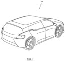
- FIG. 1 shows a schematic representation of a vehicle 200 which has at least one energy storage system 100 with a multiplicity of lithium-ion cells 10 .
- Energy storage system 100 can be arranged in a front area of vehicle 200 in the direction of travel, in a rear area of vehicle 200 and/or in an area below the seats, in particular below the driver's seat.
- Vehicle 200 can be an aircraft or water vehicle, a track-guided vehicle, an all-terrain vehicle, or preferably a road vehicle, road vehicle being understood to mean a passenger car, a truck, a bus or a mobile home.
- the vehicle 200 is driven by a power unit.
- the drive unit may include an internal combustion engine, an electric motor, or a combination thereof.
- a vehicle 200 that is driven solely by an electric motor is referred to as an electric vehicle.
- a vehicle 200 which has both an electric motor and an internal combustion engine is referred to as a hybrid vehicle.
- Hybrid vehicles can be further subdivided into micro-hybrid vehicles, mild hybrid vehicles, full hybrid vehicles, and/or plug-in hybrid vehicles.
- plug-in hybrid vehicles can be understood to mean any hybrid vehicle that is not only charged via the internal combustion engine, but can also be charged via the power grid.
- Full hybrid vehicles are vehicles that can be driven solely by the electric motor.
- Micro-hybrid vehicles have a start-stop functionality, and preferably also a stop-in-motion functionality. Furthermore, in micro-hybrid vehicles, the energy storage system 100 can be charged via what is known as braking energy recovery. Mild hybrid vehicles can also have a boost function, which is used to support the combustion engine to increase performance.
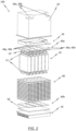
- FIG. 2 12 shows a schematic exploded view of an energy storage system 100 according to the present invention. Accordingly, the energy storage system 100 has a multiplicity of lithium-ion cells 10, each lithium-ion cell 10 having a positive pole and a negative pole.
- the lithium-ion cells 10 can be designed in such a way that the positive pole and the negative pole are arranged on two opposite sides of the lithium-ion cell 10 .
- Each lithium-ion cell 10 is designed as a so-called jelly-roll cell, which is advantageously associated with a compact and space-saving design of the lithium-ion cells 10 .
- the lithium-ion cells 10 are provided without their own housing 20, which can advantageously reduce the material and production costs, since saving the cell housing eliminates one production step.
- the lithium-ion cells 10 are also arranged in a housing 20 .
- the housing 20 is made up of a plurality of wall elements which form an inner space. The interior space is delimited by inner surfaces of the wall elements of the housing 20 .
- the wall elements of the housing 20 form a wall here.
- the housing 20 has an opening in the wall, via which the lithium-ion cells 10 can be accommodated in the housing 20 .
- the opening extends at least in regions over a surface of a wall element, preferably the opening extends over the entire surface of a wall element. This means that the housing 20 is designed to be open on the side of one wall element.
- the housing 20 can have indentations in two corner regions, which in particular are rectangular in shape.
- the depressions are each formed in such a way that their bottom surfaces form electrical connection surfaces 26 .
- a first connection surface 26a is designed as a positive connection surface 26a and a second connection surface 26b as a negative connection surface 26b.
- one connection terminal of the energy storage system 100 can be connected to one electrical connection surface 26 in each case.
- the housing 20 In order to be able to manufacture the housing 20 in a cost-efficient and simple, but nevertheless robust manner, various requirements must be met. On the one hand, the overall weight of the energy storage system 100 must not be increased in order not to reduce the efficiency of the energy storage system 100 .
- the interior of the housing 20 must be sealed off from the environment, in particular hermetically sealed.
- Hermetic generally means impenetrable. A hermetic seal thus describes an absolutely tight seal, in particular an exchange of gases or liquids preventing closure.
- Hermetically sealing the interior of the housing 20 is therefore understood to mean sealing the housing 20 in such a way that the interior is tightly sealed, specifically in such a way that a material exchange, in particular the exchange of gases and/or liquids, is prevented.
- an energy storage system whose interior is sealed only from gases from the ambient air, from gases that arise in the interior of the housing 20 during operation, and from moisture from the environment is referred to as hermetically sealed or as hermetically sealed.
- a housing 20 made of plastic is selected according to the invention.
- an acryl-butadiene-styrene, polycarbonate, polyamide, polyvinyl chloride, polyethylene terephthalate, polyoxymethylene or a copolymer thereof can be selected.
- plastics are characterized at least essentially by a relatively high permeability or semi-permeability to gases and/or liquids.
- Permeability is the property of a solid to allow gases and/or liquids to pass through.
- the transport of gases and/or liquids through the solid is referred to as permeation.
- the permeation can be divided into the following three steps, namely: adsorption, which corresponds to the uptake of the gas and/or liquid on the surface of the solid, diffusion, which corresponds to the penetration of the gas and/or liquid through the corresponds to the solid, and desorption, which corresponds to the leaving or exit of the gas and/or liquid from the solid.
- Semipermeability is the property of a solid to be only partially permeable, i.e. to only let through molecules below a certain molar mass or colloids or particles below a certain size. In what follows, the term "permeability" means both permeability and semi-permeability.
- a barrier layer 22 is therefore arranged between the interior of the housing 20 and the inner surfaces of the housing 20 delimiting the interior, at least in regions, preferably over the entire surface.
- the barrier layer 22 is designed to prevent gases and/or liquids from entering or exiting the interior of the housing 20 .
- a barrier layer 22 is generally understood to mean a layer which has relatively good barrier properties.
- barrier properties are understood as meaning no or only slight permeability of gases and/or liquids.
- the barrier layer 22 is understood to mean a layer whose permeability is lower than the permeability of the housing 20.
- barrier layer means a layer that is impermeable to gases in the ambient air, to gases that arise in the interior of the housing 20 during operation of the energy storage system 100, and to moisture in the environment.
- the interior of the housing 20 is hermetically sealed from the external environment with the aid of such a barrier layer, among other things.
- the barrier layer 22 is composed of metal and/or metal oxide.
- the metal can be or comprise a light metal, in particular aluminum and/or an aluminum alloy or magnesium and/or a magnesium alloy.
- the barrier layer 22 can be cohesively connected to the inner surfaces of the housing 20 at least in some areas; in particular, the barrier layer 22 can be steamed onto the inner surfaces of the housing 20 . This is preferably done via chemical vapor deposition or physical vapor deposition.
- the barrier layer 22 can be configured as a film, at least in some areas, in particular completely, which is connected to the inner surfaces of the housing 20 .
- This is preferably a metal foil which is materially bonded to the inner surfaces of the housing 20 .
- each pole of a lithium-ion cell 10 can be connected or can be connected to a respective current collecting element 12 .
- the lithium-ion cells 10 can be arranged in a cell carrier 80.
- the cell carrier 80 has a large number of recesses and is designed in such a way that a lithium-ion cell 10 is accommodated in each recess.
- the lithium-ion cells 10 can then be placed precisely in the interior of the housing 20 with the aid of the cell carrier 80 .
- an energy storage system 100 may have at least one busbar 60a, 60b from a plurality of busbar elements.
- the bus bar 60a, 60b is connected to the lithium-ion cells 10 in such a way that the cells are connected in series or in parallel.
- a series connection of the lithium-ion cells 10 is provided when a higher operating voltage of the energy storage system 100 is required.
- a parallel connection of the lithium-ion cells 10 is provided.
- busbar 60a has a positive connection element 66a and a negative connection element 66b, as shown in FIG. 2 is indicated schematically.
- busbar 60a, 60b can be connected to the lithium-ion cells 10 via the current collecting elements 12 . This is preferably done via a welded connection.
- the current collection elements 12 between the busbar 60a, 60b and the lithium-ion cells 10 can be arranged.
- one current collecting element 12 can preferably be connected to one pole of a lithium-ion cell 10 via a plug-in connection.
- the current collecting elements 12 can advantageously be connected simply and quickly via such a connection. It is also conceivable to connect a current collector element 12 to a pole of a lithium-ion cell 10 via a welded connection.
- the current collecting elements 12 can be further connected to the bus bar 60a, 60b via a plurality of elongate elements 12' which are arranged on a surface of the current collecting elements 12 which is on a side opposite to the lithium ion cells 10, and in such a way that the elongate elements 12' at least partially extend through recesses in the busbar 60a, 60b.
- Each elongate element 12′, which extends at least in regions through a recess in the busbar 60a, 60b, can preferably be connected to this via a welded connection.
- the busbar 60a, 60b can also be connected to the cell carrier 80.
- the busbar 60a, 60b is preferably connected to the cell carrier 80 made of plastic by caulking, in particular hot caulking.
- the cell carrier 80 should have an undercut in a region accommodating the busbar 60a, 60b, into which the busbar 60a, 60b can be inserted.
- the busbar 60a, 60b which is preferably made of metal, in particular aluminum, an aluminum alloy, copper or a copper alloy, with which Cell carrier 80 are connected, which is preferably made of plastic, in particular polyamide, polyethylene terephthalate, polycarbonate, polyoxymethylene and / or polyolefins such as polypropylene and / or polyethylene.
- FIG. 2 also indicates that an electronics mount 40 can be provided in an upper area of the interior of the housing 20 .
- the electronics carrier 40 can be made of plastic. Plastics from the group of polyamides, polyethylene terephthalates, polyoxymethylene, polycarbonates, acryl-butadiene-styrene, polyolefins and/or polyvinyl chlorides are particularly suitable.
- the electronics carrier 40 is designed to be accommodated in the housing 20 .
- the electronics mount 40 is formed at least essentially from a flat base element and a wall, the wall being designed in such a way that the electronics mount 40 can be accommodated in the upper region of the interior of the housing 20, in particular in such a way that the wall of the Electronics carrier 40 of the inner contour of the housing 20 - and in particular the inner contour of the wells - follows.
- contact surfaces 46 extend as an extension of the base element in the areas in which the recesses of the housing 20 are or can be accommodated. It is provided here that the contact surfaces 46 each make electrical contact with a first surface of a connection surface 26 of the housing 20 .
- the contact surfaces 46 are arranged in particular in such a way that the contact surfaces 46 electrically contact a respective connection element 66a, 66b of the busbar 60a with a second surface opposite the first surface.
- the electronics carrier 40 is provided in the housing 20 of the energy storage system 100 in order to accommodate a variety of electronic devices.
- the electronics mount 40 can have sensors for monitoring one and/or more lithium-ion cells 10 , and a microprocessor, a non-volatile memory unit and/or a control unit can also be accommodated in the electronics mount 40 .
- the electronics carrier 40 can be provided as a separate component in the interior of the housing 20, which is associated with a simple manufacturing and arrangement method. However, it is also conceivable to integrate the electronics mount 40 into the housing 20 . In this case, the electronics mount 40 corresponds at least in regions to a wall element of the housing 20. In particular, the electronics mount 40 replaces a wall element of the housing 20. To this end, the barrier layer between the inner surfaces of the remaining wall elements and a surface of the electronics mount 40 and arranged in the interior.
- the energy storage system 100 is also designed in such a way that the opening of the housing 20 is closed or can be closed with the aid of the cover device 30, in particular is hermetically closed.
- the cover device 30 is connected or designed to be connectable to the housing 20 in such a way that the cover device 30 forms an outer surface of the housing 20 closed in this way, at least in certain areas.
- the covering device 30 is preferably designed as a cooling device.
- the cooling device can have a large number of cooling elements and is designed to regulate the temperature of the energy storage system 100 , in particular in the interior of the housing 20 . This includes both the dissipation of heat that arises during operation of the lithium-ion cells 10 and, if necessary, the supply of heat in order to ensure an optimal operating temperature.
- the cooling device can have a metallic cooling plate.
- the metal cooling plate can also have a large number of cooling fins and/or cooling channels.
- the cooling device can be made of aluminum and/or an aluminum alloy.
- the housing 20 can advantageously be easily attached to the cover device 30 connected, as the connection is ideally made using layers of the same material.
- the covering device 30 can be welded to the housing 20 .
- the housing 20 of the energy storage system 100 also has a connection area 24 which is designed to connect the housing 20 to the covering device 30 .
- the connecting area 24 extends outward perpendicularly to the housing 20, in particular perpendicularly to the wall elements surrounding the opening. It should be noted here that the barrier layer is also arranged along the connecting region 24 in such a way that the barrier layer is not interrupted. The connection area 24 is accordingly arranged in such a way that the connection area 24 is at least essentially parallel to the surface of the covering device 30 via which the housing 20 is connected or can be connected to the covering device 30 . As a result, the production and the assembly can be optimized, since the production tolerances can be selected to be comparatively larger in this case. The connection area 24 is also easily accessible.
- the housing 20 can be connected to the cover device 30 by means of fusion welding or pressure welding.
- the connecting region 24 in such a way that it corresponds at least essentially to an extension of the wall of the housing 20, with the connecting region 24 being designed to accommodate outer side surfaces of the covering device 30 .
- the housing 20 is connected to the outer side surfaces of the cover device 30 via the connection region 24 or is designed to be connectable to them.
- a heat conducting element 50 can be provided in the interior of the housing 20 of the energy storage system 100 . This can be arranged in particular on the surface of the covering device 30 in the direction of the interior.
- the thermally conductive element 50 can be made of thermally conductive and electrically insulating material.
- the heat-conducting element 50 is preferably made from silicone-based materials.
- the thermally conductive element 50 helps to dissipate the heat generated during the operation of lithium-ion cells 10 from the interior of the energy storage system 100 . This improves the service life of the components used, in particular the cell carrier 80 made of plastic.
- the heat is conducted here in particular from the lithium-ion cells 10 via the current collector elements 12 and the busbar 60a, 60b to the heat-conducting element 50, and preferably from the heat-conducting element 50 via the cooling device to the outside.
- FIG. 3 shows an exemplary and schematic representation of an energy storage system 100 according to the invention in a sectional view.
- the energy storage system 100 has a housing 20 composed of a multiplicity of wall elements, which has an opening which extends at least in regions along a surface of a wall element. In the exemplary representation according to FIG. 3 , the opening extends over the entire surface of the lower wall element.
- FIG. 3 FIG. 2 further shows an exemplary connection area 24 of the housing 20, which extends perpendicularly outwardly from the housing 20, such that the connection area 24 is at least substantially parallel to a top surface of the cover device 30, which is to be connected to the housing 20 should.
- a barrier layer 22 is arranged between the inner surfaces of the housing 20 and the interior space, the barrier layer 22 also extending further along the connection area 24 in such a way that the barrier layer 22 is not interrupted at any point.
- a heat-conducting element 50 is arranged between the cover device 30 and the busbar 60a, 60b, which is designed to dissipate the heat generated during operation of the lithium-ion cells 10 to the outside via the cover device 30.
- the covering device 30 is preferably designed as a cooling device.
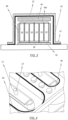
- FIG. 4 shows an exemplary additional seal between a cell carrier 80 and a busbar 60a of an energy storage system 100.
- a sealing element 82 is arranged along a recess of a cell carrier 80, in which a lithium-ion cell 10 can be accommodated. If the busbar 60a is now connected to the cell carrier 80, the recess of the cell carrier 80 is sealed off from the interior of the energy storage system 100 at the same time. As a result, the operation of lithium-ion cells 10 is advantageously further increased since it is made more difficult for moisture and/or gases to penetrate and escape.
- the seal 82 is required in order to keep the electrolyte, in particular the liquid electrolyte, in the lithium-ion cells 10, so that in particular each lithium-ion cell 10 has its own cell space sealed against liquids (against the electrolyte). . Otherwise, a short circuit via the electrolyte could lead to increased self-discharge of the cell arrangement.
- This seal 82 advantageously prevents the electrolyte from leaking out.
- busbars 60a, 60b can also be used to seal the respective cell spaces inside the cell carrier 80, which means that additional sealing elements can be dispensed with.
- the structure of the energy storage system 100 is further simplified.
- an energy storage system 100 can be provided whose housing 20 has a barrier layer 22 which exclusively prevents gas exchange between the interior of the housing 20 and an exterior space outside of the energy storage system 100 .
- the seal 82 seals one or more cell spaces, which are formed by the recesses in the cell carrier 80 and the cell spaces are designed to each accommodate a lithium-ion cell 10, against liquids.
- the lithium-ion cells 10 particularly preferably do not have their own cell housing; rather, the cell carrier 80 forms the cell housing.
- the seal is advantageously designed to keep the electrolyte, in particular the liquid electrolyte, inside the lithium-ion cells 10 or in the cell spaces formed by the recesses in the cell carrier 80 .
- the cell carrier 80 can accommodate lithium-ion cells 10 of different shapes.
- the cell carrier 80 must have recesses corresponding to the individual cells.
- cells of the same type are preferably provided. This leads to simpler manufacture and assembly of the cells in the cell carrier 80.
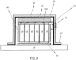
- FIG. 5 shows a schematic representation of a gas collection channel 70 which is formed in an upper region of the interior of energy storage system 100.
- the gas escaping from the individual lithium-ion cells 10 can flow into the gas-collecting duct 70 via a labyrinth, which is integrated in the current-collecting elements 12 and the busbar 60a, 60b.
- the gas collection channel 70 is arranged in an upper area of the interior of the housing 20 and in a lateral area of the interior of the housing 20 .
- the gas collection channel 70 can just as easily be integrated into the housing 20 .
- the gas collection channel 70 can preferably also be formed between the cell carrier 80 and the electronics carrier 40 .
- the gas collection channel 70 can be associated with all lithium-ion cells 10 and thus be a common gas collection space 70 .
- a membrane 72 can be provided on the housing 20 as a gas collection channel outlet.
- the membrane 72 is preferably integrated into the housing 20 .
- the membrane 72 may also be a bursting membrane designed to rupture at a relatively high pressure, particularly rupturing when an internal pressure exceeds a predetermined or determinable internal pressure. In the worst case, this means that an energy storage system 100 based on lithium-ion technologies breaks down in a controlled manner. As a result, the operational reliability can be increased and, in addition, a relatively safe replacement and/or removal of the defective energy storage system 100 can be ensured.
- the integration of the functionality of the bursting membrane can also be integrated into the housing 20 itself, namely into the housing 20 and into the barrier layer 22. This advantageously keeps the number of parts of the energy storage system 100 low, which leads to lower production and manufacturing costs.
- the diaphragm 72 may be formed as a disk-shaped plastic component having a substantially flat bottom (i.e., surface toward an interior of the housing 20) and a profiled top (i.e., surface toward an exterior of the housing 20).
- the profiled upper side can have a raised central area and a raised edge area with increased material thicknesses, with the (annular) area between the central area and the edge area having a lower material thickness.
- the thickness of the material within the ring-shaped area can decrease steplessly.
- the central area and the edge area can also have the same material thickness. However, it is just as conceivable that the edge area has a thicker material thickness than the middle area.
- the membrane can in particular be integrated directly into the housing 20 .
- the membrane 72 is not designed as a separate component, but that the profiling is introduced directly into the housing 20 itself, specifically in a region of the housing 20 where the gas collection channel outlet is provided.
- the housing 20 can be a metal housing with a (thin) plastic layer for electrical (and thermal) insulation. This can prevent moisture and/or gases and the like from entering or leaving the housing, while at the same time electrical (and thermal) insulation can be ensured via the plastic layer.
Landscapes
- Chemical & Material Sciences (AREA)
- Chemical Kinetics & Catalysis (AREA)
- Electrochemistry (AREA)
- General Chemical & Material Sciences (AREA)
- Engineering & Computer Science (AREA)
- Manufacturing & Machinery (AREA)
- Inorganic Chemistry (AREA)
- Aviation & Aerospace Engineering (AREA)
- Battery Mounting, Suspending (AREA)
Description
- Diese Anmeldung betrifft ein Energiespeichersystem auf der Basis von Lithium-Ionen-Zellen, insbesondere zum Einsatz in einem Fahrzeug, bevorzugt ein Energiespeichersystem zum Einsatz in einem Hybrid-Fahrzeug.
- In den letzten Jahren spielen Energiespeichersysteme, welche auf Lithium-Ionen-Technologien basieren, eine immer wichtigere Rolle, insbesondere im Hinblick darauf, ein effizientes Energiespeichersystem bereitzustellen, welches eine hohe Leistung bringen kann.
- Beim Verwenden der Lithium-Ionen-basierten Energiespeichersysteme muss auf eine Abdichtung der die Lithium-Ionen-Technologie enthaltenden Elemente geachtet werden. Dringt nämlich Wasser in derartige Elemente ein, so kann dieses reagieren und es besteht aufgrund von starker Wärmeentwicklung Brand- und Verpuffungsgefahr.
- Daher werden Energiespeichersysteme, welche auf Lithium-Ionen-Technologien basieren, herkömmlicherweise derart gefertigt, dass die einzelnen Lithium-Ionen-Zellen einzeln mit einem Zellgehäuse zu ihrer Umgebung hin abgedichtet werden.
- Dies weist allerdings den Nachteil auf, dass die Herstellung solcher Energiespeichersysteme vergleichsweise aufwendig ist. Des Weiteren führt dies zu einer Steigerung der Produktionskosten und zu einer Erhohung der Produktionszeit.
-
DE 10 2012 205 810 A1 offenbart ein Energiespeichersystem zum Einsatz in einem Fahrzeug, das eine Vielzahl von Lithiumzellen mit jeweils einem positiven und einem negativen Pol, ein Gehäuse mit einem Innenraum zum Aufnehmen der Lithiumzellen, wobei das Gehäuse ein Hartschalengehäuse aus Kunststoff ist und eine Öffnung aufweist, und wobei zwischen dem Innenraum und den den Innenraum begrenzenden Innenflächen des Gehäuses eine Dampfsperrschicht angeordnet ist, welche eine Schicht ist die gegenüber von Gasen in einer Umgebungsluft und Gasen die während eines Betriebs des Energiespeichersystems im Innenraum entstehen und gegenüber Feuchtigkeit in der Umgebung undurchlässig ist, sowie eine Abdeckeinrichtung aufweist. Das Gehäuse ist an den Innenflächen mit einer Dampfsperrschicht versehen, welche Eindringen von Feuchtigkeit in das Gehäuseinnere verhindert. Die Dampfsperrschicht kann beispielsweise eine metallische Schicht, organische Schicht /polymere Schicht oder eine gläserne Schicht sein. -
FR 3 014 635 A1 - Da ferner zur gesicherten Abdichtung überwiegend metallische Zellgehäuse verwendet werden, erhöht sich dadurch auch das Gesamtgewicht des Energiespeichersystems, was insbesondere in Bezug auf den Einsatz in einem Fahrzeug nicht erwünscht ist.
- Der Erfindung liegt daher die Aufgabe zugrunde, ein verbessertes, einfaches und robustes Energiespeichersystem bereitzustellen, welches die Nachteile des Standes der Technik nicht aufweist und zudem einfach und kostengünstig herzustellen ist.
- Im Hinblick auf das Energiespeichersystem wird die der Erfindung zugrunde liegende Aufgabe erfindungsgemäß durch den Gegenstand des unabhängigen Patentanspruchs 1 gelöst. Vorteilhafte Weiterbildungen sind in den abhängigen Patentansprüchen angegeben.
- Demnach wird erfindungsgemäß ein Energiespeichersystem, insbesondere zum Einsatz in einem Fahrzeug, bevorzugt zum Einsatz in einem Hybrid-Fahrzeug, angegeben. Das Energiespeichersystem weist hierbei Folgendes auf: eine Vielzahl von Lithium-Ionen-Zellen mit jeweils einem positiven Pol und einem negativen Pol, ein Gehäuse mit einem Innenraum zum Aufnehmen der Lithium-Ionen-Zellen, und eine Abdeckeinrichtung. Das Gehäuse ist zumindest bereichsweise, insbesondere vollständig, aus Kunststoff gebildet und weist eine Öffnung auf. Zwischen dem Innenraum und den den Innenraum begrenzenden Innenflächen des Gehäuses ist zumindest bereichsweise, insbesondere vollständig, d.h. auf der gesamten Innenfläche des Gehäuses, eine Barriereschicht angeordnet. Die Abdeckeinrichtung ist derart mit dem Gehäuse verbunden oder verbindbar, dass die Öffnung des Gehäuses verschlossen oder verschließbar ist, sodass die Abdeckeinrichtung zumindest bereichsweise eine Außenfläche des so verschlossenen Gehäuses bildet.
- Die Vorteile der Erfindung liegen auf der Hand. Durch das erfindungsgemäße Energiespeichersystem kann das Gehäuse aus kostengünstigen, gut verformbaren Werkstoffen gefertigt werden. Durch das Vorsehen einer Barriereschicht zwischen dem Innenraum und den den Innenraum begrenzenden Innenflächen des Gehäuses ist das Vorsehen einzelner Zellengehäuse für die Lithium-Ionen-Zellen überflüssig. Aufgrund der vorteilhaften Integration der Abdichtungsfunktionalität in das Gehäuse bzw. die Barriereschicht kann die Teileanzahl des Energiespeichersystems vorteilhafterweise reduziert werden. Auch werden dadurch die benötigten Verfahrensschritte zum Herstellen und Zusammensetzen des Energiespeichersystems reduziert. Dadurch kann ein kompaktes, kostengünstiges und robustes Energiespeichersystem bereitgestellt werden, dass zudem einfach zu fertigen ist. Auch werden dadurch die oben genannten Nachteile bezüglich des Gewichts des Energiespeichersystems umgangen. Dadurch, dass das Gehäuse aus einem Kunststoff gefertigt wird, kann überdies das Gesamtgewicht des Energiespeichersystems ferner reduziert werden, und zwar ohne Funktionseinschränkungen, insbesondere ohne Einbußen in der Dichtheit des Energiespeichersystems.
- Erfindungsgemäß kann die Öffnung des Gehäuses mit der Abdeckeinrichtung, und zwar mit Hilfe der Barriereschicht, hermetisch verschließbar oder verschlossen sein.
- Dadurch wird vorteilhafterweise der Gasaustausch und/oder Flüssigkeitsaustausch bereits auf Gehäuseebene verhindert. Daher sind keine zusätzlichen Schutzvorkehrungen, wie gesonderte Zellgehäuse für die einzelnen Lithium-Ionen-Zellen, mehr nötig. Dadurch kann die Teileanzahl des Energiespeichersystems gering gehalten werden. Zusätzlich werden vorteilhafterweise Funktionalitäten wie das Abdichten gegenüber von Gasen und/oder Flüssigkeiten von der Zellebene auf die Gehäuseebene übertragen.
- Gemäß einem weiteren Aspekt der Erfindung kann die Barriereschicht aus mindestens einem der folgenden Materialien gebildet sein: Siliziumoxid, Aluminiumoxid, Silikate, Ethylen-Vinylalkohol-Copolymer, Aluminium und Magnesium.
- Dabei handelt es sich um Materialien, die eine geringe Permeabilität und/oder einen niedrigen Permeationskoeffizienten aufweisen. Daher sind solche Materialien vorteilhafterweise undurchlässig gegenüber von Gasen und/oder Flüssigkeiten. Dies verbessert die Dichtheit des Energiespeichersystems. Ferner sind solche Materialien vergleichsweise kostengünstig und gut verarbeitbar.
- Erfindungsgemäß ist die Abdeckeinrichtung aus einem metallischen Werkstoff gebildet.
- Da auch hier ein Material mit geringer Permeabilität und/oder mit niedrigen Permeationskoeffizienten verwendet wird, wird das Eintreten bzw. Austreten von Flüssigkeiten und/oder Gasen in bzw. aus dem Energiespeichersystem vorzugsweise verhindert. Insbesondere kann die Funktionalität des Abdichtens des Gehäuses in die Abdeckeinrichtung integriert werden. Dies wiederum spart weitere Elemente bzw. weitere Fertigungsschritte ein.
- Gemäß einem weiteren Aspekt der Erfindung kann die Barriereschicht zumindest bereichsweise, insbesondere vollständig, mit den Innenflächen des Gehäuses stoffschlüssig verbunden sein, insbesondere auf die Innenflächen des Gehäuses gedampft sein.
- Dies liefert den Vorteil, dass der Übergang zwischen Gehäuse und Barriereschicht verbessert wird, was wiederum die Dichtungseigenschaften und die Stabilität des Energiespeichersystems erhöht.
- Gemäß einem weiteren Aspekt der Erfindung kann die Barriereschicht zumindest bereichsweise, bevorzugt vollständig, aus einer Folie gebildet sein, welche mit den Innenflächen des Gehäuses verbunden ist, insbesondere stoffschlüssig verbunden ist.
- Das Ausbilden der Barriereschicht als Folie führt vorteilhafterweise dazu, dass weniger Defekte innerhalb der Barriereschicht entstehen können, bzw. dass weniger Stelle vorhanden sind, an denen keine Beschichtung erfolgt ist. Daher ist das Vorsehen der Barriereschicht als Folie einfach und sicher.
- Erfindungsgemäß ist die mit dem Gehäuse verschweißbar. Dies führt vorteilhafterweise zu einem hermetischen Verschluss des Innenraums des Gehäuses. Das heißt, dass der Innenraum des Gehäuses geschützt ist, und zwar vor dem Eintreten bzw. Austreten von Gasen und/oder Flüssigkeiten aus dem Gehäuse bzw. in das Gehäuse. Ferner ist eine solche stoffschlüssige Verbindung einfach realisierbar und fertigbar.
- Erfindungsgemäß weist das Gehäuse einen Verbindungsbereich auf, welcher dazu ausgelegt ist, das Gehäuse mit der Abdeckeinrichtung zu verbinden. Dadurch wird vorteilhafterweise eine einfachere Fertigung des Energiespeichersystems geschaffen.
- Erfindungsgemäß erstreckt sich der Verbindungsbereich senkrecht von dem Gehäuse nach außen hin weg, und zwar derart, dass das Gehäuse über den Verbindungsbereich mit der Abdeckeinrichtung verbunden oder verbindbar ist.
- Dies liefert den Vorteil, dass der Verbindungsbereich besser zugänglich ist, und dadurch einfacher zu fertigen ist.
- Gemäß einem weiteren Aspekt der Erfindung kann der Verbindungsbereich einer Verlängerung einer Wandung des Gehäuses entsprechen, welche äußere Seitenflächen der Abdeckeinrichtung aufnimmt, und zwar derart, dass das Gehäuse über den Verbindungsbereich mit den äußeren Seitenflächen der Abdeckeinrichtung verbunden oder verbindbar ist.
- Dies birgt den Vorteil, dass der Verbindungsbereich zum einen über die Aufnahme der äußeren Seitenflächen der Abdeckeinrichtung bereits zentriert ist, und zum anderen gut zugänglich und dadurch einfach zu fertigen ist.
- Generell kann das Energiespeichersystem ferner einen Elektronik-Träger aufweisen. Dieser ist dazu ausgelegt, elektronische Komponenten - wie Prozessoren, Speicher, Sensoren und dergleichen - aufzunehmen.
- Generell kann das Energiespeichersystem ein Wärmeleitelement aufweisen, welches auf einer Oberfläche der Abdeckeinrichtung in Richtung des Innenraums des Gehäuses angeordnet ist.
- Das Wärmeleitelement verbessert die Wärmeableitung bzw. die Wärmeübertragung von dem Innenraum des Gehäuses nach außen hin, und schützt dadurch die im Inneren des Gehäuses angeordneten Elemente aus Kunststoff. Dadurch kann ferner vorteilhafterweise die Effizienz des Energiespeichersystems gesteigert werden.
- Generell kann die Abdeckeinrichtung als Kühleinrichtung zur Temperaturregulierung des Energiespeichersystems ausgebildet sein. Dadurch wird vorteilhafterweise die Funktion der Kühlung des Energiespeichersystems in die Abdeckeinrichtung integriert, was dazu führt, dass die Teileanzahl weiter reduziert wird.
- Generell kann die Kühleinrichtung eine metallische Kühlplatte aufweisen, insbesondere eine Kühlplatte mit einer Vielzahl von Kühllamellen und Kühlkanälen, wobei die Kühleinrichtung vorzugsweise zumindest bereichsweise, insbesondere vollständig, aus Aluminium und/oder aus einer Aluminiumlegierung gefertigt ist. Dies liefert den Vorteil, dass die Effizienz der Kühleinrichtung gesteigert wird und gleichzeitig ein geringes Gewicht bei guter thermischer Leitfähigkeit erzielt wird.
- Generell kann das Energiespeichersystem eine Vielzahl von Stromsammelelementen aufweisen, wobei jeweils ein Stromsammelelement mit einem Pol der Vielzahl von Lithium-Ionen-Zellen verbunden oder verbindbar ist. Dadurch wird eine einfache Ab- bzw. Weiterleitung des Zellenstroms gewährleistet.
- Generell kann das Energiespeichersystem mindestens eine Sammelschiene aus einer Vielzahl von Sammelschienenelementen aufweisen. Über die mindestens eine Sammelschiene kann vorteilhafterweise der benötigte Strom bzw. die benötigte Spannung durch eine Reihen- bzw. Parallelschaltung der einzelnen Lithium-Ionen-Zellen relativ einfach eingestellt werden.
- Generell kann die Vielzahl von Stromsammelelementen verbindbar mit einer der mindestens einen Sammelschiene ausgebildet sein, bevorzugt nicht lösbar verbindbar und besonders bevorzugt über eine Schweißverbindung verbindbar. Dies liefert den Vorteil, dass ein geringer elektrischer Widerstand im Übergangsbereich von der Vielzahl von Stromsammelelementen zur Sammelschiene austritt, und daher der elektrische Fluss bzw. die elektrische Leitfähigkeit verbessert wird.
- Generell kann die Vielzahl von Stromsammelelementen und die mindestens eine Sammelschiene ein Labyrinth ausbilden, welches dazu ausgelegt ist, ein während des Betriebs in der Vielzahl von Lithium-Ionen-Zellen entstehendes Gas in einen Gassammelkanal zu leiten. Dies liefert den Vorteil, dass kein zusätzliches Element bzw. keine zusätzlichen Elemente benötigt werden, um Gas aus den Zellen abzuleiten. Dies führt zu einer Reduzierung der Gesamtteileanzahl im Energiespeichersystem.
- Generell kann der Sammelkanal zumindest in einem oberen Bereich des Innenraums des Gehäuses angeordnet sein, bevorzugt in einem oberen und in einem seitlichen Bereich des Gehäuses, wobei der Gassammelkanal insbesondere in das Gehäuse integriert ist.
- Dies führt vorteilhafterweise zu einer Reduzierung der Teileanzahl des Energiespeichersystems und darüber hinaus kann das Energiespeichersystem einfacher und kostengünstiger gefertigt werden.
- Generell kann eine Membran an dem Gehäuse als Gassammelkanal-Begrenzung vorgesehen sein, vorzugsweise in dem Gehäuse integriert sein, wobei die Membran bevorzugt als Berstmembran ausgebildet ist. Dies führt ebenso vorteilhafterweise zu einer Reduzierung der Teileanzahl des Energiespeichersystems und zu einer einfacheren und kostengünstigeren Fertigung.
- Generell kann der Gassammelkanal aus nicht-entflammbarem Material gebildet sein, insbesondere sind Bereiche des Gehäuses, die den Gassammelkanal bilden, aus nicht-entflammbarem Material gebildet.
- Dies liefert den Vorteil, dass Bereiche, in denen der Gassammelkanal vorgesehen ist, nicht leicht zu brennen anfangen können. Dadurch wird die Sicherheit des Energiespeichersystems verbessert.
- Generell kann das Energiespeichersystem einen Zellenträger aus Kunststoff aufweisen, der dazu ausgelegt ist, die Vielzahl von Lithium-Ionen-Zellen aufzunehmen und diese innerhalb des Gehäuses zu platzieren.
- Dies liefert den Vorteil, dass die Herstellung des Energiespeichersystems vereinfacht wird, und zwar dahingehend, dass die Lithium-Ionen-Zellen außerhalb des Gehäuses in dem Zellenträger platziert werden können und anschließend zusammen in das Gehäuse eingeführt werden können ohne jede einzelne Lithium-Ionen-Zelle genau zentrieren und/oder anordnen zu müssen.
- Generell kann die mindestens eine Sammelschiene mittels Verstemmen, insbesondere Heißverstemmen, mit dem Zellenträger verbunden sein. Verstemmen oder Heißverstemmen ist eine einfache und kostengünstige Art zwei Elemente aus verschiedenen Materialien miteinander zu verbinden. Dadurch kann das Fertigungsverfahren vereinfacht werden.
- Generell kann zwischen dem Zellenträger und der Sammelschiene ein Dichtelement vorgesehen sein. Dadurch wird vorteilhafterweise ein Raum, in dem jeweils eine Lithium-Ionen-Zelle aufgenommen werden kann, zusätzlich abgedichtet. Dadurch verringert sich das Risiko, dass Feuchtigkeit in die Lithium-Ionen-Zelle eindringen kann.
- Die Erfindung wird nachstehend, auch hinsichtlich weiterer Merkmale und Vorteile, anhand der Beschreibung von Ausführungsformen unter Bezugnahme auf die beiliegenden Zeichnungen näher erläutert.
- Diese zeigen in:
- FIG. 1
- eine schematische Darstellung eines Fahrzeugs;
- FIG. 2
- eine schematische Darstellung eines Energiespeichersystems gemäß der vorliegenden Erfindung;
- FIG. 3
- eine schematische Schnittdarstellung des erfindungsgemäßen Energiespeichersystems;
- FIG. 4
- eine schematische Darstellung einer Abdichtung zwischen einem Zellenträger und einer Sammelschiene (nicht Teil der vorliegenden Erfindung); und
- FIG. 5
- eine schematische Darstellung eines Gassammelkanals in einem Energiespeichersystem (nicht notwendigerweise Teil der vorliegenden Erfindung).
- Nachfolgend wird das erfindungsgemäße Energiespeichersystem unter Bezugnahme auf die Darstellungen in den
FIGS. 1 bis 5 genauer beschrieben. Gleiche oder gleichwirkende Elemente und Funktionen sind mit demselben oder ähnlichen Bezugszeichen versehen. - Energiespeichersysteme, welche auf Lithium-Ionen-Technologien basieren, eignen sich insbesondere zum Einsatz in Fahrzeugen 200. Des Weiteren kann ein solches Energiespeichersystem 100 ebenfalls überall dort eingesetzt werden, wo Energiespeichersysteme mit einer relativ hohen Leistungsdichte gefordert sind.
- Im Folgenden wird das Energiespeichersystem 100 derart beschrieben, dass relative Begriffe auf den Einbau-Zustand des Energiespeichersystems 100 bezogen sind. So bedeutet beispielsweise "in einem oberen Bereich" in einem im eingebauten Zustand gesehenen oberen Bereich, "in einem seitlichen Bereich" in einem im eingebauten Zustand gesehenen Bereich, der sich in einem linken oder rechten Bereich befindet, und "in einem unteren Bereich" in einem im eingebauten Zustand gesehenen unteren Bereich.
-
FIG. 1 zeigt eine schematische Darstellung eines Fahrzeugs 200, welches mindestens ein Energiespeichersystem 100 mit einer Vielzahl von Lithium-Ionen-Zellen 10 aufweist. Das Energiespeichersystem 100 kann hierbei in einem in Fahrtrichtung vorderen Bereich des Fahrzeugs 200, in einem hinteren Bereich des Fahrzeugs 200 und/oder in einem Bereich unterhalb der Sitze, insbesondere unterhalb des Fahrersitzes angeordnet sein. - Das Fahrzeug 200 kann ein Luft- oder Wasserfahrzeug, ein spurgeführtes Fahrzeug, ein Geländefahrzeug, oder bevorzugt ein Straßenfahrzeug sein, wobei unter Straßenfahrzeug ein Personenkraftwagen, ein Lastkraftwagen, ein Bus oder ein Wohnmobil verstanden werden kann.
- Das Fahrzeug 200 wird durch eine Antriebseinheit angetrieben. Die Antriebseinheit kann einen Verbrennungsmotor, einen Elektromotor oder eine Kombination davon umfassen. Ein Fahrzeug 200, welches ausschließlich mit einem Elektromotor angetrieben wird, wird als Elektro-Fahrzeug bezeichnet. Ein Fahrzeug 200, welches sowohl einen Elektromotor, als auch einen Verbrennungsmotor aufweist, wird als Hybrid-Fahrzeug bezeichnet. Hybrid-Fahrzeuge können ferner in Mikrohybrid-Fahrzeuge, Mildhybrid-Fahrzeug, Vollhybrid-Fahrzeuge und/oder Plug-In-Hybrid-Fahrzeuge untergliedert werden. Hierbei kann unter Plug-In-Hybrid-Fahrzeugen jedwedes Hybridfahrzeug verstanden werden, welches nicht nur über den Verbrennungsmotor aufgeladen wird, sondern ebenfalls über das Stromnetz geladen werden kann. Unter Vollhybrid-Fahrzeugen werden Fahrzeuge verstanden, die allein über den Elektromotor angetrieben werden können. Mikrohybrid-Fahrzeuge verfügen über eine Start-Stopp-Funktionalität, und vorzugsweise ebenso über eine Stopp-In-Motion-Funktionalität. Des Weiteren können Mikrohybrid-Fahrzeuge das Energiespeichersystem 100 über eine sogenannte Bremsenergierückgewinnung aufgeladen werden. Mildhybrid-Fahrzeuge können darüber hinaus über eine Boost-Funktion verfügen, welche zur Unterstützung des Verbrennungsmotors zur Leistungssteigerung verwendet wird.
-
FIG. 2 zeigt eine schematische Explosionsdarstellung eines Energiespeichersystems 100 gemäß der vorliegenden Erfindung. Demnach weist das Energiespeichersystem 100 eine Vielzahl von Lithium-Ionen-Zellen 10 auf, wobei jede Lithium-Ionen-Zelle 10 jeweils einen positiven Pol und einen negativen Pol aufweist. - Die Lithium-Ionen-Zellen 10 können derart ausgebildet sein, dass jeweils der positive Pol und der negative Pol an zwei sich gegenüberliegenden Seiten der Lithium-Ionen-Zelle 10 angeordnet sind.
- Jede Lithium-Ionen-Zelle 10 ist als sogenannte Jelly-Roll-Zelle ausgebildet, was vorteilhafterweise mit einer kompakten und platzsparenden Bauweise der Lithium-Ionen-Zellen 10 einhergeht.
- Erfindungsgemäß werden die Lithium-Ionen-Zellen 10 ohne eigenes Gehäuse 20 bereitgestellt, was vorteilhafterweise die Material- und Produktionskosten senken kann, da durch das Einsparen des Zellgehäuses ein Produktionsschritt entfällt.
- Die Lithium-Ionen-Zellen 10 sind ferner in einem Gehäuse 20 angeordnet. Das Gehäuse 20 ist aus einer Vielzahl von Wandelementen gebildet, welche einen Innenraum formen. Der Innenraum wird durch Innenflächen der Wandelemente des Gehäuses 20 begrenzt. Die Wandelemente des Gehäuses 20 bilden hierbei eine Wandung aus. Ferner weist das Gehäuse 20 eine Öffnung in der Wandung auf, über welche die Lithium-Ionen-Zellen 10 in dem Gehäuse 20 aufnehmbar sind.
- Die Öffnung erstreckt sich zumindest bereichsweise über eine Fläche eines Wandelements, vorzugsweise erstreckt sich die Öffnung über die Gesamtfläche eines Wandelements. Das heißt, dass das Gehäuse 20 auf der Seite des einen Wandelements offen ausgebildet ist.
- Wie in
FIG. 2 schematisch dargestellt, kann das Gehäuse 20 in zwei Eckbereichen Vertiefungen aufweisen, welche insbesondere rechteckig geformt sind. Die Vertiefungen sind jeweils derart ausgebildet, dass deren Bodenflächen elektrische Anschlussflächen 26 ausbilden. Dabei ist eine erste Anschlussfläche 26a als positive Anschlussfläche 26a und eine zweite Anschlussfläche 26b als negative Anschlussfläche 26b ausgebildet. Jeweils eine Anschlussklemme des Energiespeichersystems 100 kann hierbei mit jeweils einer elektrischen Anschlussfläche 26 verbunden werden. - Um das Gehäuse 20 kosteneffizient und einfach, aber dennoch widerstandsfähig fertigen zu können, müssen verschiedene Voraussetzungen eingehalten werden. Zum einen darf das Gesamtgewicht des Energiespeichersystems 100 nicht vergrö-βert werden, um die Effizienz des Energiespeichersystems 100 nicht herabzusetzen. Zum anderen muss der Innenraum des Gehäuses 20 gegenüber der Umgebung dicht abgeschlossen sein, insbesondere hermetisch abgeschlossen sein. Hermetisch hat im Allgemeinen die Bedeutung undurchdringlich. Ein hermetischer Verschluss beschreibt somit einen absolut dichten, insbesondere einen Austausch von Gasen oder Flüssigkeiten verhindernden Abschluss. Unter hermetischem Verschließen des Innenraums des Gehäuses 20 wird daher verstanden, das Gehäuse 20 derart zu verschließen, dass der Innenraum dicht verschlossen ist, und zwar so, dass ein Stoffaustausch, insbesondere der Austausch von Gasen und/oder Flüssigkeiten, verhindert wird. In diesem Zusammenhang wird auch ein Energiespeichersystem, dessen Innenraum nur gegenüber Gasen aus der Umgebungsluft, gegenüber Gasen, die im Betrieb in dem Innenraum des Gehäuses 20 entstehen, und gegenüber Feuchtigkeit aus der Umgebung abgedichtet ist, als hermetisch abgedichtet oder als hermetisch verschlossen bezeichnet.
- Um das Energiespeichersystem 100 möglichst leicht zu gestalten, wird erfindungsgemäß ein Gehäuse 20 aus Kunststoff gewählt. Dabei kann beispielsweise ein Acryl-Butadien-Styrol, Polycarbonat, Polyamid, Polyvinylchlorid, Polyethylenterephthalat, Polyoxymethylen oder ein Copolymer hiervon gewählt werden.
- Allerdings zeichnen sich Kunststoffe zumindest im Wesentlichen durch eine relativ hohe Permeabilität oder Semipermeabilität gegenüber von Gasen und/oder Flüssigkeiten aus.
- Unter Permeabilität wird die Eigenschaft eines Festkörpers verstanden, Gase und/oder Flüssigkeiten passieren zu lassen. Der Transport von Gase und/oder Flüssigkeiten durch den Festkörper wird als Permeation bezeichnet. Die Permeation kann hierbei in die folgenden drei Schritte unterteilt werden, und zwar: die Adsorption, was der Aufnahme des Gases und/oder der Flüssigkeit auf der Oberfläche des Festkörpers entspricht, die Diffusion, was dem Durchdringen des Gases und/oder der Flüssigkeit durch den Festkörper entspricht, und die Desorption, was dem Verlassen oder Ausdringen des Gases und/oder der Flüssigkeit aus dem Festkörper entspricht. Unter Semipermeabilität versteht man die Eigenschaft eines Festkörpers, nur teilweise durchlässig zu sein, d.h. nur Moleküle unterhalb einer bestimmten Molmasse bzw. Kolloide oder Partikel unterhalb einer bestimmten Größe durchzulassen. Im weiteren Verlauf ist unter der Bezeichnung "Permeabilität" sowohl die Permeabilität als auch die Semipermeabilität gemeint.
- Daher ist zwischen dem Innenraum des Gehäuses 20 und den den Innenraum begrenzenden Innenflächen des Gehäuses 20 zumindest bereichsweise, bevorzugt auf der gesamten Fläche, eine Barriereschicht 22 angeordnet. Die Barriereschicht 22 ist dazu ausgebildet, den Ein- bzw. Austritt von Gasen und/oder Flüssigkeiten in den bzw. aus dem Innenraum des Gehäuses 20 zu verhindern.
- Unter einer Barriereschicht 22 wird im Allgemeinen eine Schicht verstanden, welche relativ gute Barriereeigenschaften aufweist. Unter Barriereeigenschaften wird wiederum keine oder nur eine geringfügige Durchlässigkeit von Gasen und/oder Flüssigkeiten verstanden. Insbesondere wird unter der Barriereschicht 22 eine Schicht verstanden, deren Permeabilität geringer ist als die Permeabilität des Gehäuses 20.
- In diesem Zusammenhang ist unter mit dem Begriff "Barriereschicht" eine Schicht gemeint, die gegenüber Gasen in der Umgebungsluft, gegenüber Gasen, welche im Betrieb des Energiespeichersystems 100 in dem Innenraum des Gehäuses 20 entstehen, und gegenüber Feuchtigkeit in der Umgebung undurchlässig ist. Insbesondere wird unter anderem mithilfe einer solchen Barriereschicht der Innenraum des Gehäuses 20 hermetisch von der äußeren Umgebung abgedichtet.
- Die Barriereschicht 22 ist hierbei aus Metall und/oder Metalloxid aufgebaut. Das Metall kann ein Leichtmetall sein bzw. aufweisen, insbesondere Aluminium und/oder eine Aluminiumlegierung oder Magnesium und/oder eine Magnesiumlegierung.
- Die Barriereschicht 22 kann zumindest bereichsweise mit den Innenflächen des Gehäuses 20 stoffschlüssig verbunden sein, insbesondere kann die Barriereschicht 22 auf die Innenflächen des Gehäuses 20 gedampft sein. Dies geschieht bevorzugt über chemische Gasphasenabscheidung oder physikalische Gasphasenabscheidung.
- Ebenso kann die Barriereschicht 22 zumindest bereichsweise, insbesondere vollständig, als Folie ausgebildet sein, welche mit den Innenflächen des Gehäuses 20 verbunden ist. Bevorzugt handelt es sich hierbei um eine Metallfolie, welche stoffschlüssig mit den Innenflächen des Gehäuses 20 verbunden ist.
- Alternativ ist es auch denkbar, das Gehäuse 20 derart zu formen, dass ein zwei-oder mehrlagiges Material aus mindestens einer Kunstoffschicht und der Barriereschicht 22 tiefgezogen wird, und zwar derart, dass die Barriereschicht 22 in Richtung des Innenraums des tiefgezogenen Gehäuses 20 angeordnet ist. Somit kann schon das Vormaterial des Gehäuses 20, d. h. das Material aus dem das Gehäuse 20 gefertigt werden soll, mit der Barriereschicht 22 verbunden sein, insbesondere stoffschlüssig verbunden sein, was die Herstellung des Gehäuses 20 vereinfacht und somit zu Kosteneinsparungen und Aufwandsverringerung führen kann. Ferner kann jeder Pol einer Lithium-Ionen-Zelle 10 mit jeweils einem Stromsammelelement 12 verbunden oder verbindbar sein.
- Um eine einfachere und genauere Montage der Lithium-Ionen-Zellen 10 zu gewährleisten, können die Lithium-Ionen-Zellen 10 in einem Zellenträger 80 angeordnet sein. Der Zellenträger 80 weist eine Vielzahl von Ausnehmungen auf und ist derart ausgebildet, dass jeweils eine Lithium-Ionen-Zelle 10 in einer Ausnehmung aufgenommen wird. Anschließend können die Lithium-Ionen-Zellen 10 mit Hilfe des Zellenträgers 80 präzise im Innenraum des Gehäuses 20 platziert werden.
- Des Weiteren ist in
FIG. 2 dargestellt, dass ein Energiespeichersystem 100 mindestens eine Sammelschiene 60a, 60b aus einer Vielzahl von Sammelschienenelementen aufweisen kann. Die Sammelschiene 60a, 60b ist derart mit den Lithium-Ionen-Zellen 10 verbunden, dass die Zellen in Reihe oder parallel geschaltet werden. Eine Reihenschaltung der Lithium-Ionen-Zellen 10 wird dann vorgesehen, wenn eine höhere Betriebsspannung des Energiespeichersystems 100 gefordert ist. Wenn allerdings eine höhere Kapazität des Energiespeichersystems 100 gefordert ist, wird eine Parallelschaltung der Lithium-Ionen-Zellen 10 vorgesehen. - Dabei ist anzumerken, dass die Sammelschiene 60a je ein positives Anschlusselement 66a und ein negatives Anschlusselement 66b aufweist, wie es in
FIG. 2 schematisch angedeutet ist. - Des Weiteren kann die Sammelschiene 60a, 60b über die Stromsammelelemente 12 mit den Lithium-Ionen-Zellen 10 verbunden werden. Dies geschieht bevorzugt über eine Schweißverbindung.
- Wie in
FIG. 2 ferner dargestellt ist, können die Stromsammelelemente 12 zwischen der Sammelschiene 60a, 60b und den Lithium-Ionen-Zellen 10 angeordnet sein. Hierbei kann vorzugsweise jeweils ein Stromsammelelement 12 über eine Steckverbindung mit je einem Pol einer Lithium-Ionen-Zelle 10 verbunden sein. Über eine solche Verbindung können die Stromsammelelemente 12 vorteilhafterweise einfach und schnell verbunden werden. Ebenso ist es denkbar, jeweils ein Stromsammelelement 12 über eine Schweißverbindung mit einem Pol einer Lithium-Ionen-Zelle 10 zu verbinden. - Die Stromsammelelemente 12 können ferner über eine Vielzahl von länglichen Elementen 12', welche auf einer Oberfläche der Stromsammelelemente 12 angeordnet sind, die sich auf einer Seite gegenüberliegend von den Lithium-Ionen-Zellen 10 befindet, mit der Sammelschiene 60a, 60b verbunden werden, und zwar derart, dass sich die länglichen Elemente 12' zumindest bereichsweise durch Ausnehmungen in der Sammelschiene 60a, 60b erstrecken. Vorzugsweise kann jedes längliche Element 12', das sich zumindest bereichsweise durch eine Ausnehmung in der Sammelschiene 60a, 60b erstreckt, mit dieser über eine Schweißverbindung verbunden werden.
- Die Sammelschiene 60a, 60b kann ferner mit dem Zellenträger 80 verbunden sein. Vorzugsweise wird die Sammelschiene 60a, 60b mittels Verstemmen, insbesondere Heißverstemmen, mit dem Zellenträger 80 aus Kunststoff verbunden.
- Des Weiteren ist es denkbar, die Sammelschiene 60a, 60b formschlüssig mit dem Zellenträger 80 zu verbinden. Hierfür sollte der Zellenträger 80 in ein die Sammelschiene 60a, 60b aufnehmenden Bereich eine Hinterschneidung aufweisen, in die die Sammelschiene 60a, 60b eingesetzt werden kann.
- Das Heißverstemmen eignet sich insbesondere für das Verbinden von Komponenten mit unterschiedlichen Materialien. So kann vorteilhafterweise die Sammelschiene 60a, 60b, welche bevorzugt aus Metall, insbesondere Aluminium, einer Aluminiumlegierung, Kupfer oder einer Kupferlegierung, gefertigt ist, mit dem Zellenträger 80 verbunden werden, welcher bevorzugt aus Kunststoff, insbesondere Polyamid, Polyethylenterephthalat, Polycarbonat, Polyoxymethylen und/oder Polyolefine, wie Polypropylen und/oder Polyethylen, gefertigt sein.
-
FIG. 2 deutet ferner an, dass in einem oberen Bereich des Innenraums des Gehäuses 20 einen Elektronik-Träger 40 vorgesehen sein kann. Der Elektronik-Träger 40 kann hierbei aus Kunststoff ausgebildet sein. Insbesondere eignet sich Kunststoff der Gruppe von Polyamiden, Polyethylenterephthalaten, Polyoxymethylen, Polycarbonaten, Acryl-Butadien-Styrol, Polyolefinen und/oder Polyvinylchloriden. Der Elektronik-Träger 40 ist dazu ausgebildet, in das Gehäuse 20 aufgenommen zu werden. - Der Elektronik-Träger 40 ist zumindest im Wesentlichen aus einem ebenen Bodenelement und einer Wandung geformt, wobei die Wandung derart ausgebildet ist, dass der Elektronik-Träger 40 in den oberen Bereich des Innenraums des Gehäuses 20 aufnehmbar ist, insbesondere derart, dass die Wandung des Elektronik-Trägers 40 der Innenkontur des Gehäuses 20 - und insbesondere der Innenkontur der Vertiefungen - folgt.
- Ferner erstrecken sich Kontaktflächen 46 als Verlängerung des Bodenelements in den Bereichen, in welchen die Vertiefungen des Gehäuses 20 aufgenommen werden bzw. aufnehmbar sind. Hierbei ist vorgesehen, dass die Kontaktflächen 46 mit einer ersten Oberfläche jeweils eine Anschlussfläche 26 des Gehäuses 20 elektrisch kontaktieren.
- Weiterhin sind die Kontaktflächen 46 insbesondere derart angeordnet, dass die Kontaktflächen 46 mit einer der ersten Oberfläche gegenüberliegenden zweiten Oberfläche jeweils ein Anschlusselement 66a, 66b der Sammelschiene 60a elektrisch kontaktieren.
- Der Elektronik-Träger 40 ist in dem Gehäuse 20 des Energiespeichersystems 100 vorgesehen, um eine Vielzahl von elektronischen Vorrichtungen aufnehmen zu können. So kann der Elektronik-Träger 40 beispielsweise Sensoren zur Überwachung einer und/oder mehrerer Lithium-Ionen-Zellen 10 aufweisen, ferner können ebenso ein Mikroprozessor, eine nicht flüchtige Speichereinheit und/oder eine Steuereinheit in dem Elektronik-Träger 40 aufgenommen werden.
- Der Elektronik-Träger 40 kann als separates Bauteil in dem Innenraum des Gehäuses 20 vorgesehen sein, was mit einer einfachen Herstellungs- und Anordnungsverfahren einhergeht. Es ist aber auch denkbar, den Elektronik-Träger 40 in das Gehäuse 20 zu integrieren. Hierbei entspricht der Elektronik-Träger 40 zumindest bereichsweise einem Wandelement des Gehäuses 20. Insbesondere ersetzt der Elektronik-Träger 40 ein Wandelement des Gehäuses 20. Dazu wird die Barriereschicht zwischen den Innenflächen der übrigen Wandelemente sowie einer dem Innenraum zugewandten Fläche des Elektronik-Trägers 40 und dem Innenraum angeordnet.
- Das erfindungsgemäße Energiespeichersystem 100 ist ferner derart ausgebildet, dass die Öffnung des Gehäuses 20 mit Hilfe der Abdeckeinrichtung 30 verschlossen ist oder verschließbar ist, insbesondere hermetisch verschlossen ist. Hierzu ist die Abdeckeinrichtung 30 verbunden oder verbindbar mit dem Gehäuse 20 ausgebildet, und zwar derart, dass die Abdeckeinrichtung 30 zumindest bereichsweise eine Außenfläche des so verschlossenen Gehäuses 20 bildet.
- Vorzugsweise ist die Abdeckeinrichtung 30 als Kühleinrichtung ausgebildet. Die Kühleinrichtung kann eine Vielzahl von Kühlelementen aufweisen und ist dazu ausgelegt, die Temperatur des Energiespeichersystems 100, insbesondere im Innenraum des Gehäuses 20, zu regulieren. Dies beinhaltet sowohl das Ableiten von Wärme, welche während des Betriebs der Lithium-Ionen-Zellen 10 entsteht, als auch gegebenenfalls das Zuführen von Wärme, um eine optimale Betriebstemperatur zu gewährleisten.
- Die Kühleinrichtung kann eine metallische Kühlplatte aufweisen. Die metallische Kühlplatte kann ferner eine Vielzahl von Kühllamellen und/oder Kühlkanälen aufweisen.
- Die Kühleinrichtung kann aus Aluminium und/oder einer Aluminiumlegierung gefertigt sein.
- Auch ist es denkbar, dass eine weitere Barriereschicht 22 auf einer Oberfläche der Abdeckeinrichtung 30 in Richtung des Innenraums vorgesehen ist. Dadurch kann das Gehäuse 20 vorteilhafterweise einfach mit der Abdeckeinrichtung 30 verbunden werden, da die Verbindung idealerweise über Schichten aus dem gleichen Material hergestellt wird. Erfindungsgemäß ist die Abdeckeinrichtung 30 verschweißbar mit dem Gehäuse 20 ausgebildet.
- Das Gehäuse 20 des Energiespeichersystems 100 weist ferner einen Verbindungsbereich 24 auf, welcher dazu ausgelegt ist, das Gehäuse 20 mit der Abdeckeinrichtung 30 zu verbinden.
- Der Verbindungsbereich 24 erstreckt sich zum einen senkrecht zu dem Gehäuse 20 nach außen hin weg, insbesondere senkrecht zu den die Öffnung umfassenden Wandelementen. Dabei ist zu beachten, dass die Barriereschicht auch entlang des Verbindungsbereiches 24 angeordnet ist, und zwar derart, dass die Barriereschicht nicht unterbrochen ist. Der Verbindungsbereich 24 ist dementsprechend derart angeordnet, dass der Verbindungsbereich 24 zumindest im Wesentlichen parallel zu der Fläche der Abdeckeinrichtung 30 ist, über die das Gehäuse 20 mit der Abdeckeinrichtung 30 verbunden oder verbindbar ist. Dadurch kann die Fertigung, sowie die Montage optimiert werden, da die Fertigungstoleranzen in diesem Fall vergleichsweise größer gewählt werden können. Auch ist der Verbindungsbereich 24 gut zugänglich.
- Das Gehäuse 20 kann mittels Schmelzschweißen oder Pressschweißen mit der Abdeckeinrichtung 30 verbunden werden.
- Auch wenn dies nicht explizit in den Zeichnungen dargestellt ist, ist es auch denkbar, den Verbindungsbereich 24 derart auszubilden, dass er zumindest im Wesentlichen einer Verlängerung der Wandung des Gehäuses 20 entspricht, wobei der Verbindungsbereich 24 dazu ausgebildet ist, äußere Seitenflächen der Abdeckeinrichtung 30 aufzunehmen. Hierbei wird das Gehäuse 20 über den Verbindungsbereich 24 mit den äußeren Seitenflächen der Abdeckeinrichtung 30 verbunden oder ist mit diesen verbindbar ausgebildet.
- Ferner kann in dem Innenraum des Gehäuses 20 des Energiespeichersystems 100 ein Wärmeleitelement 50 vorgesehen sein. Dies kann insbesondere auf der Oberfläche der Abdeckeinrichtung 30 in Richtung des Innenraums angeordnet sein.
- Das Wärmeleitelement 50 kann aus thermisch leitfähigen und elektrisch isolierenden Material gefertigt sein. Bevorzugt ist das Wärmeleitelement 50 aus Silikonbasierten Materialien gefertigt.
- Das Wärmeleitelement 50 hilft dabei, die während des Betriebs von Lithium-Ionen-Zellen 10 entstehende Wärme aus dem Innenraum des Energiespeichersystems 100 abzuleiten. Dies verbessert die Lebensdauer der eingesetzten Komponenten, insbesondere des Zellenträgers 80 aus Kunststoff. Die Wärmeleitung erfolgt hierbei insbesondere von den Lithium-Ionen-Zellen 10 über die Stromsammelelemente 12 und die Sammelschiene 60a, 60b zu dem Wärmeleitelement 50, und bevorzugt von dem Wärmeleitelement 50 über die Kühleinrichtung nach au-βen.
-
FIG. 3 zeigt eine exemplarische und schematische Darstellung eines erfindungsgemäßen Energiespeichersystems 100 in einer Schnittansicht. Das Energiespeichersystem 100 weist ein Gehäuse 20 aus einer Vielzahl von Wandelementen auf, welches eine Öffnung aufweist, die sich zumindest bereichsweise entlang einer Fläche eines Wandelements erstreckt. In der beispielhaften Darstellung gemäßFIG. 3 , erstreckt sich die Öffnung über die gesamte Fläche des unteren Wandelements. -
FIG. 3 zeigt ferner einen exemplarischen Verbindungsbereich 24 des Gehäuses 20, welcher sich senkrecht von dem Gehäuse 20 nach außen hin erstreckt, und zwar derart, dass der Verbindungsbereich 24 zumindest im Wesentlichen parallel zu einer oberen Fläche der Abdeckeinrichtung 30 ist, die mit dem Gehäuse 20 verbunden werden soll. - Des Weiteren ist erkennbar, dass eine Barriereschicht 22 zwischen den Innenflächen des Gehäuses 20 und dem Innenraum angeordnet ist, wobei die Barriereschicht 22 sich auch ferner entlang des Verbindungsbereich 24 erstreckt, und zwar so, dass die Barriereschicht 22 an keiner Stelle unterbrochen ist.
- Zwischen der Abdeckeinrichtung 30 und der Sammelschiene 60a, 60b ist exemplarisch ein Wärmeleitelement 50 angeordnet, welches dazu ausgelegt ist, die während des Betriebs der Lithium-Ionen-Zellen 10 entstehenden Wärme über die Abdeckeinrichtung 30 nach außen abzuleiten. Die Abdeckeinrichtung 30 ist hierzu vorzugsweise als Kühleinrichtung ausgebildet.
-
FIG. 4 zeigt eine beispielhafte zusätzliche Abdichtung zwischen einem Zellenträger 80 und einer Sammelschiene 60a eines Energiespeichersystems 100. Hierbei ist ein Dichtelement 82 entlang einer Ausnehmung eines Zellenträgers 80 angeordnet, in welche eine Lithium-Ionen-Zelle 10 aufgenommen werden kann. Wenn nun die Sammelschiene 60a mit dem Zellenträger 80 verbunden wird, wird gleichzeitig die Ausnehmung des Zellenträgers 80 gegenüber dem Innenraum des Energiespeichersystems 100 abgedichtet. Dadurch wird vorteilhafterweise der Betrieb von Lithium-Ionen-Zellen 10 weiterhin erhöht, da ein Eindringen und Ausdringen von Feuchtigkeit und/oder Gasen erschwert wird. - Darüber hinaus ist die Dichtung 82 erforderlich, um den Elektrolyten, insbesondere den flüssigen Elektrolyten, in den Lithium-Ionen-Zellen 10 zu halten, damit insbesondere jede Lithium-Ionen-Zelle 10 einen eigenen, gegen Flüssigkeiten (gegen den Elektrolyten) abgedichteten Zellenraum aufweist. Ansonsten könnte über den Elektrolyten ein Kurzschluss zu erhöhter Selbstentladung der Zellanordnung führen. Aufgrund dieser Dichtung 82 wird vorteilhafterweise das Auslaufen des Elektrolyten verhindert.
- Somit können die Sammelschienen 60a, 60b auch zum Abdichten der jeweiligen Zellenräume im Inneren des Zellenträgers 80 verwendet werden, wodurch auf zusätzliche Dichtelemente verzichtet werden kann. Somit wird der Aufbau des Energiespeichersystems 100 weiter vereinfacht.
- Beispielsweise kann dabei ein Energiespeichersystem 100 vorgesehen sein, dessen Gehäuse 20 eine Barriereschicht 22 aufweist, welche ausschließlich einen Gasaustausch zwischen dem Innenraum des Gehäuses 20 und einem Außenraum außerhalb des Energiespeichersystems 100 verhindert. Die Dichtung 82 dichtet dabei einen bzw. mehrere Zellenräume, welche von den Ausnehmungen in dem Zellenträger 80 ausgebildet sind, und wobei die Zellenräume dazu ausgebildet sind, jeweils eine Lithium-Ionen-Zelle 10 aufzunehmen, gegen Flüssigkeiten ab.
- Besonders bevorzugt weisen die Lithium-Ionen-Zellen 10 hierbei kein eigenes Zellengehäuse auf; vielmehr bildet der Zellenträger 80 das Zellengehäuse. Die Dichtung ist dabei vorteilhafterweise dazu ausgebildet, den Elektrolyten, insbesondere den flüssigen Elektrolyten, im Inneren der Lithium-Ionen-Zellen 10, bzw. den durch die Ausnehmungen in dem Zellenträger 80 gebildeten Zellenräumen, zu halten.
- Des Weiteren ist schematisch angedeutet, dass der Zellenträger 80 Lithium-Ionen-Zellen 10 unterschiedlicher Formen aufnehmen kann. Dazu muss der Zellenträger 80 den einzelnen Zellen entsprechende Ausnehmungen aufweisen. Vorzugsweise sind allerdings gleichartige Zellen vorgesehen. Dies führt zu einer einfacheren Fertigung und Montage der Zellen in dem Zellenträger 80.
-
FIG. 5 zeigt eine schematische Darstellung eines Gassammelkanals 70, welcher in einem oberen Bereich des Innenraums des Energiespeichersystems 100 ausgebildet ist. Hierbei kann das aus den einzelnen Lithium-Ionen-Zellen 10 austretende Gas über ein Labyrinth, welches in den Stromsammelelementen 12 und die Sammelschiene 60a, 60b integriert ist, in den Gassammelkanal 70 strömen. Insbesondere ist der Gassammelkanal 70 in einem oberen Bereich des Innenraums des Gehäuses 20 und in einem seitlichen Bereich des Innenraums des Gehäuses 20 angeordnet. Der Gassammelkanal 70 kann genauso gut in das Gehäuse 20 integriert sein. Bevorzugt kann der Gassammelkanal 70 aber auch zwischen dem Zellenträger 80 und dem Elektronik-Träger 40 ausgebildet sein. Der Gassammelkanal 70 kann dabei allen Lithium-Ionen-Zellen 10 zugehörig sein und somit ein gemeinsamer Gassammelraum 70 sein. - Ferner kann eine Membran 72 an dem Gehäuse 20 als Gassammelkanal-Auslass vorgesehen sein. Vorzugsweise ist die Membran 72 in das Gehäuse 20 integriert. Die Membran 72 kann ferner eine Berstmembran sein, welche dazu ausgelegt ist, bei einem relativ hohen Druck zu bersten, insbesondere zu bersten, wenn ein Innendruck einen vorherbestimmten oder bestimmbaren Innendruck übertrifft. Dies führt dazu, dass ein Energiespeichersystem 100 basierend auf Lithium-Ionen-Technologien im schlimmsten Fall kontrolliert kaputtgehen. Dadurch kann die Betriebssicherheit erhöht werden und zudem ein relativ sicheres Austauschen und/oder Entfernen des defekten Energiespeichersystems 100 gewährleistet werden.
- Die Integration der Funktionalität der Berstmembran kann auch in das Gehäuse 20 selbst integriert werden, und zwar in das Gehäuse 20 und in die Barriereschicht 22. Dadurch wird vorteilhafterweise die Teileanzahl des Energiespeichersystems 100 geringgehalten, was zu geringeren Herstellungs- und Fertigungskosten führt.
- Insbesondere kann die Membran 72 als scheibenförmiges Kunststoff-Bauteil ausgebildet sein, das eine im Wesentlichen flache Unterseite (d. h. Fläche in Richtung Innenraum des Gehäuses 20) und eine profilierte Oberseite (d. h. Fläche in Richtung eines Äußeren des Gehäuses 20) aufweist. Die profilierte Oberseite kann dabei einen erhöhten Mittelbereich und einen erhöhten Randbereich mit erhöhten Materialstärken aufweisen, wobei der (ringförmige) Bereich zwischen dem Mittelbereich und dem Randbereich eine geringere Materialstärke aufweist. Dabei kann die Materialstärke innerhalb des ringförmigen Bereichs stufenlos abnehmen. Auch können der Mittelbereich und der Randbereich die gleiche Materialstärke aufweisen. Genauso gut ist es allerdings denkbar, dass der Randbereich eine dickere Materialstärke aufweist als der Mittelbereich. Die Membran kann dabei insbesondere direkt in das Gehäuse 20 integriert sein. Auch ist es alternativ denkbar, dass die Membran 72 nicht als separates Bauteil ausgebildet ist, sondern dass die Profilierung direkt in das Gehäuse 20 selbst eingebracht ist, und zwar insbesondere in einem Bereich des Gehäuses 20, wo der Gassammelkanal-Auslass vorgesehen ist.
- Es ist auch denkbar, das Gehäuse 20 auch ein Metallgehäuse sein mit einer (dünnen) Kunststoffschicht zur elektrischen (und thermischen) Isolation auszubilden. Dadurch kann ein Eintritt von Feuchtigkeit und/oder Gasen und dergleichen in bzw. aus dem Gehäuse verhindert werden, während gleichzeitig eine elektrische (und thermische) Isolation über die Kunststoffschicht gewährleistet werden kann.
-
- 10
- Lithium-Ionen-Zelle
- 12
- Stromsammelelement
- 12'
- längliches Element
- 20
- Gehäuse
- 22
- Barriereschicht
- 24
- Verbindungsbereich
- 26 (26a, 26b)
- Anschlussflächen
- 30
- Abdeckeinrichtung
- 40
- Elektronik-Träger
- 46 (46a, 46b)
- Kontaktflächen
- 50
- Wärmeleitelement
- 60a, 60b
- Sammelschiene
- 66 (66a, 66b)
- Anschlusselement
- 70
- Gassammelkanal
- 72
- Membran
- 80
- Zellenträger
- 82
- Dichtelement
- 100
- Energiespeichersystem
- 200
- Fahrzeug
Claims (7)
- Energiespeichersystem (100) zum Einsatz in einem Fahrzeug (200), bevorzugt zum Einsatz in einem Hybrid-Fahrzeug (200), wobei das Energiespeichersystem (100) Folgendes aufweist:- eine Vielzahl von Lithium-Ionen-Zellen (10) mit jeweils einem positiven Pol und einem negativen Pol, wobei jede der Lithium-Ionen-Zellen (10) ohne Zellengehäuse als Jelly-Roll-Zelle ausgebildet ist;- ein Gehäuse (20) mit einem Innenraum zum Aufnehmen der Lithium-Ionen-Zellen (10), wobei das Gehäuse (20) zumindest bereichsweise aus Kunststoff gebildet ist und eine Öffnung aufweist, und wobei zwischen dem Innenraum und den den Innenraum begrenzenden Innenflächen des Gehäuses (20) zumindest bereichsweise eine Barriereschicht (22) aus Metall und/oder Metalloxid angeordnet ist, wobei die Barriereschicht (22) eine Schicht ist, die gegenüber von Gasen in einer Umgebungsluft und Gasen, die während eines Betriebs des Energiespeichersystems (100) in dem Innenraum entstehen, und gegenüber Feuchtigkeit in der Umgebung undurchlässig ist; und- eine Abdeckeinrichtung (30) aus einem metallischen Werkstoff, die mit dem Gehäuse (20) verschweißbar ausgebildet ist,wobei die Abdeckeinrichtung (30) derart mit dem Gehäuse (20) verschweißbar oder verschweißt ist, dass die Öffnung des Gehäuses (20) verschlossen oder verschließbar ist, und wobei die Abdeckeinrichtung (30) zumindest bereichsweise eine Außenfläche des so verschlossenen Gehäuses (20) bildet,dadurch gekennzeichnet, dassdas Gehäuse (20) einen Verbindungsbereich (24) aufweist, welcher dazu ausgelegt ist, das Gehäuse (20) mit der Abdeckeinrichtung (30) zu verbinden, und entlang welchem die Barriereschicht (22) angeordnet ist, wobei sich der Verbindungsbereich (24) senkrecht von dem Gehäuse (20) nach außen hin weg erstreckt, und zwar derart, dass das Gehäuse (20) über den Verbindungsbereich (24) mit der Abdeckeinrichtung (30) verschweißt oder verschweißbar ist, undwobei die Öffnung des Gehäuses (20) mit der Abdeckeinrichtung (30) mithilfe der Barriereschicht (22) hermetisch verschließbar oder verschlossen ist.
- Energiespeichersystem (100) nach Anspruch 1, wobei die Barriereschicht (22) aus mindestens einem der folgenden Materialien gegebildet ist: Siliziumoxid, Aluminiumoxid, Aluminium und Magnesium.
- Energiespeichersystem (100) nach Anspruch 1 oder 2, wobei die Barriereschicht (22) zumindest bereichsweise mit den Innenflächen des Gehäuses (20) stoffschlüssig verbunden ist, insbesondere auf die Innenflächen des Gehäuses (20) gedampft ist.
- Energiespeichersystem (100) nach einem der Ansprüche 1 bis 3, wobei die Barriereschicht (22) zumindest bereichsweise aus einer Folie gebildet ist, welche mit den Innenflächen des Gehäuses (20) verbunden ist, insbesondere stoffschlüssig verbunden ist.
- Energiespeichersystem (100) nach einem der Ansprüche 1 bis 4, wobei der Verbindungsbereich (24) einer Verlängerung einer Wandung des Gehäuses (20) entspricht, welche äußere Seitenflächen der Abdeckeinrichtung (30) aufnimmt, und zwar derart, dass das Gehäuse (20) über den Verbindungsbereich (24) mit den äußeren Seitenflächen der Abdeckeinrichtung (30) verbunden oder verbindbar ist.
- Energiespeichersystem (100) nach einem der Ansprüche 1 bis 5, wobei das Energiespeichersystem (100) eine Vielzahl von Stromsammelelementen (12) aufweist, wobei jeweils ein Stromsammelelement (12) mit einem Pol der Vielzahl von Lithium-Ionen-Zellen (10) verbunden oder verbindbar ist, und/oder
wobei das Energiespeichersystem (100) mindestens eine Sammelschiene (60a, 60b) aus einer Vielzahl von Sammelschienenelementen aufweist. - Energiespeichersystem (100) nach Anspruch 6,
wobei die Vielzahl von Stromsammelelementen (12) verbindbar mit einer der mindestens einen Sammelschiene (60a, 60b) ausgebildet ist, bevorzugt nicht lösbar verbindbar, und besonders bevorzugt über eine Schweißverbindung verbindbar.
Applications Claiming Priority (2)
| Application Number | Priority Date | Filing Date | Title |
|---|---|---|---|
| DE102016118753.4A DE102016118753A1 (de) | 2016-10-04 | 2016-10-04 | Energiespeichersystem |
| PCT/EP2017/075127 WO2018065438A1 (de) | 2016-10-04 | 2017-10-04 | Energiespeichersystem |
Publications (2)
| Publication Number | Publication Date |
|---|---|
| EP3523843A1 EP3523843A1 (de) | 2019-08-14 |
| EP3523843B1 true EP3523843B1 (de) | 2023-07-05 |
Family
ID=60120019
Family Applications (1)
| Application Number | Title | Priority Date | Filing Date |
|---|---|---|---|
| EP17784907.2A Active EP3523843B1 (de) | 2016-10-04 | 2017-10-04 | Energiespeichersystem |
Country Status (5)
| Country | Link |
|---|---|
| US (1) | US12341210B2 (de) |
| EP (1) | EP3523843B1 (de) |
| CN (2) | CN120637724A (de) |
| DE (1) | DE102016118753A1 (de) |
| WO (1) | WO2018065438A1 (de) |
Families Citing this family (13)
| Publication number | Priority date | Publication date | Assignee | Title |
|---|---|---|---|---|
| DE102018210151A1 (de) | 2018-06-21 | 2019-12-24 | Bayerische Motoren Werke Aktiengesellschaft | Fahrzeug mit einem Hochvoltspeicher |
| DE102018210152A1 (de) * | 2018-06-21 | 2019-12-24 | Bayerische Motoren Werke Aktiengesellschaft | Fahrzeug mit einem Hochvoltspeicher |
| DE102018125457A1 (de) * | 2018-10-15 | 2020-04-16 | Webasto SE | Einlegeteil zum Einlegen in ein Batteriegehäuse einer Batteriesystemanordnung und Batteriesystemanordnung |
| CN209183604U (zh) | 2018-12-27 | 2019-07-30 | 宁德时代新能源科技股份有限公司 | 电池箱 |
| US12300842B2 (en) * | 2019-07-29 | 2025-05-13 | Panasonic Energy Co., Ltd. | Battery pack |
| DE102020205930A1 (de) * | 2020-05-12 | 2021-11-18 | Mahle International Gmbh | Akkumulator |
| EP4016699A1 (de) * | 2020-12-17 | 2022-06-22 | Volvo Car Corporation | Temperaturregelungssystem |
| DE102021108080A1 (de) | 2021-03-30 | 2022-10-06 | Bayerische Motoren Werke Aktiengesellschaft | Bauteil für einen Energiespeicher, Verbundbauteil für einen Energiespeicher, Energiespeicher sowie Verfahren zur Herstellung eines Verbundbauteils |
| CN117397114A (zh) * | 2021-03-31 | 2024-01-12 | 艾诺维克斯公司 | 用于电化学电池的电互连系统的增强以及其系统和方法 |
| US20250141003A1 (en) * | 2022-05-26 | 2025-05-01 | Lg Energy Solution, Ltd. | Battery module and method for manufacturing the same |
| EP4560814A4 (de) * | 2022-12-02 | 2025-11-26 | Lg Energy Solution Ltd | Batteriepack |
| KR20240097570A (ko) * | 2022-12-20 | 2024-06-27 | 주식회사 엘지에너지솔루션 | 안전성이 향상된 전지 팩 |
| KR20250025186A (ko) * | 2023-08-14 | 2025-02-21 | 현대자동차주식회사 | 배터리케이스 |
Citations (4)
| Publication number | Priority date | Publication date | Assignee | Title |
|---|---|---|---|---|
| DE102013207872A1 (de) * | 2013-04-30 | 2014-10-30 | Bayerische Motoren Werke Aktiengesellschaft | Hochvoltspeicher für ein Fahrzeug |
| US20150069829A1 (en) * | 2013-09-06 | 2015-03-12 | Johnson Controls Technology Company | Systems, methods, and devices for pre-charge control of a battery module |
| FR3014635A1 (fr) * | 2013-12-09 | 2015-06-12 | Renault Sa | Equipement electrique a haute tension comportant un boitier rigide double d'un film indechirable isolant electriquement et vehicule embarquant un tel equipement |
| US20160141573A1 (en) * | 2013-03-29 | 2016-05-19 | Sanyo Electric Co., Ltd. | Battery pack |
Family Cites Families (32)
| Publication number | Priority date | Publication date | Assignee | Title |
|---|---|---|---|---|
| US20040137321A1 (en) * | 2002-11-27 | 2004-07-15 | Jean-Francois Savaria | Casing for an energy storage device |
| DE10326906B4 (de) * | 2003-06-14 | 2008-09-11 | Varta Automotive Systems Gmbh | Akkumulator und Verfahren zur Herstellung einer dichten Kontaktklemmendurchführung |
| JP4655554B2 (ja) * | 2004-09-08 | 2011-03-23 | トヨタ自動車株式会社 | 蓄電モジュール及びその製造方法 |
| KR20090092108A (ko) * | 2008-02-26 | 2009-08-31 | 도레이새한 주식회사 | 이차전지 패키지용 라미네이트 시트 및 이를 포함하는이차전지 |
| CN201435416Y (zh) | 2009-02-27 | 2010-03-31 | 丁振荣 | 防爆膜及扁平锂电池 |
| DE102009018787A1 (de) * | 2009-04-24 | 2010-10-28 | Akasol Engineering Gmbh | Batteriemodul |
| KR101393167B1 (ko) * | 2009-05-20 | 2014-05-08 | 존슨 컨트롤즈 테크놀로지, 엘엘씨 | 리튬 이온 배터리 모듈 |
| DE102010019369A1 (de) * | 2010-05-05 | 2011-11-10 | Mahle International Gmbh | Kühleinrichtung |
| KR20120044853A (ko) * | 2010-10-28 | 2012-05-08 | 현대자동차주식회사 | 플라스틱 복합재를 이용한 전기자동차용 배터리팩 케이스 어셈블리 |
| KR101191660B1 (ko) | 2010-11-08 | 2012-10-17 | 에스비리모티브 주식회사 | 전지 모듈 |
| DE102011075318A1 (de) | 2011-05-05 | 2012-11-08 | Sb Limotive Company Ltd. | Batteriegehäuse für Lithium-Ionen-Zellen |
| JP2013012441A (ja) | 2011-06-30 | 2013-01-17 | Sanyo Electric Co Ltd | 電源装置及び電源装置を備える車両 |
| DE102011080325A1 (de) * | 2011-08-03 | 2013-02-07 | Elringklinger Ag | Druckausgleichsvorrichtung für ein Gehäuse einer elektrochemischen Vorrichtung |
| DE102011088637A1 (de) * | 2011-12-15 | 2013-06-20 | Robert Bosch Gmbh | Hartschalenbatteriegehäuse mit Dampfsperrschicht |
| DE102011088636A1 (de) * | 2011-12-15 | 2013-06-20 | Robert Bosch Gmbh | Hartschalengehäuse mit superhydrophoben Material |
| DE102012205810A1 (de) * | 2012-04-10 | 2013-10-10 | Robert Bosch Gmbh | Hartschalenbatteriegehäuse mit Temperiereinrichtung |
| US20140248524A1 (en) * | 2013-03-01 | 2014-09-04 | Honeywell International Inc. | Batteries and methods of manufacturing batteries |
| CN103413989B (zh) | 2013-07-25 | 2016-11-09 | 天津市松正电动汽车技术股份有限公司 | 一种电池散热系统 |
| DE102013219969A1 (de) * | 2013-10-01 | 2015-04-02 | Continental Automotive Gmbh | Gehäuse für elektrische und elektronische Fahrzeugkomponenten, Kraftfahrzeugbatterie und Leistungselektronik- oder Steuerelektronikmodul |
| DE102014102053A1 (de) * | 2014-02-18 | 2015-08-20 | Johnson Controls Hybrid And Recycling Gmbh | Akkumulatoranordnung |
| JP6245038B2 (ja) * | 2014-03-31 | 2017-12-13 | 株式会社Gsユアサ | 蓄電装置 |
| CN203859168U (zh) | 2014-05-23 | 2014-10-01 | 河南速达电动汽车科技有限公司 | 一种阶梯型电池箱 |
| DE102014220844A1 (de) * | 2014-10-15 | 2016-04-21 | Robert Bosch Gmbh | Batteriemodulgehäuse sowie Batteriemodul, Batterie, Batteriesystem, Fahrzeug und Verfahren zur Herstellung eines Batteriemoduls |
| CN204130608U (zh) * | 2014-10-23 | 2015-01-28 | 北汽福田汽车股份有限公司 | 一种新型电池箱结构 |
| KR102288543B1 (ko) * | 2015-03-10 | 2021-08-11 | 삼성에스디아이 주식회사 | 배터리 팩 |
| JP6248972B2 (ja) * | 2015-03-23 | 2017-12-20 | トヨタ自動車株式会社 | 電池パック |
| CN204651375U (zh) | 2015-06-18 | 2015-09-16 | 合肥工业大学 | 一种轻质高强的电动汽车安全电池箱 |
| CN205177901U (zh) | 2015-10-22 | 2016-04-20 | 宁德时代新能源科技股份有限公司 | 动力电池系统的防水高压箱 |
| CN205050906U (zh) | 2015-10-30 | 2016-02-24 | 先进储能材料国家工程研究中心有限责任公司 | 液冷电池包壳体 |
| CN205069720U (zh) | 2015-11-11 | 2016-03-02 | 杭州百超精密机械有限公司 | 新能源轿车电池盒钣金件 |
| CN105552268B (zh) | 2016-01-30 | 2018-06-22 | 华南理工大学 | 一种装有散热片的多出口电动汽车电池空气冷却电池箱 |
| CN105514319B (zh) | 2016-02-24 | 2018-03-06 | 宁德时代新能源科技股份有限公司 | 电池包冷却系统 |
-
2016
- 2016-10-04 DE DE102016118753.4A patent/DE102016118753A1/de not_active Withdrawn
-
2017
- 2017-10-04 CN CN202510532265.4A patent/CN120637724A/zh active Pending
- 2017-10-04 WO PCT/EP2017/075127 patent/WO2018065438A1/de not_active Ceased
- 2017-10-04 CN CN201780061275.8A patent/CN110235271A/zh active Pending
- 2017-10-04 US US16/338,949 patent/US12341210B2/en active Active
- 2017-10-04 EP EP17784907.2A patent/EP3523843B1/de active Active
Patent Citations (4)
| Publication number | Priority date | Publication date | Assignee | Title |
|---|---|---|---|---|
| US20160141573A1 (en) * | 2013-03-29 | 2016-05-19 | Sanyo Electric Co., Ltd. | Battery pack |
| DE102013207872A1 (de) * | 2013-04-30 | 2014-10-30 | Bayerische Motoren Werke Aktiengesellschaft | Hochvoltspeicher für ein Fahrzeug |
| US20150069829A1 (en) * | 2013-09-06 | 2015-03-12 | Johnson Controls Technology Company | Systems, methods, and devices for pre-charge control of a battery module |
| FR3014635A1 (fr) * | 2013-12-09 | 2015-06-12 | Renault Sa | Equipement electrique a haute tension comportant un boitier rigide double d'un film indechirable isolant electriquement et vehicule embarquant un tel equipement |
Also Published As
| Publication number | Publication date |
|---|---|
| US20210288366A1 (en) | 2021-09-16 |
| DE102016118753A1 (de) | 2018-04-05 |
| CN120637724A (zh) | 2025-09-12 |
| US12341210B2 (en) | 2025-06-24 |
| EP3523843A1 (de) | 2019-08-14 |
| WO2018065438A1 (de) | 2018-04-12 |
| CN110235271A (zh) | 2019-09-13 |
Similar Documents
| Publication | Publication Date | Title |
|---|---|---|
| EP3523843B1 (de) | Energiespeichersystem | |
| EP3295509B1 (de) | Energiespeicher eines kraftfahrzeugs | |
| EP2656416B1 (de) | Vorrichtung zur halterung von mindestens einem batterieelement | |
| DE102009020185A1 (de) | Energiespeicher aus Batteriezellen mit Gehäuse | |
| WO2018233902A1 (de) | Flexible kühlplatte für eine batterie | |
| DE102014201165A1 (de) | Batterie-Pack mit Luftkühlung | |
| WO2018065516A1 (de) | Energiespeichermodul mit einem temperaturmanagement-system und ein energiespeichersystem | |
| DE102011088636A1 (de) | Hartschalengehäuse mit superhydrophoben Material | |
| EP2980882B1 (de) | Rahmen für elektrochemische zellen | |
| DE102020123152A1 (de) | Traktionsbatterievorrichtung für ein Fahrzeug sowie Kraftfahrzeug mit einer Traktionsbatterievorrichtung | |
| EP3679609A1 (de) | Batteriezelle mit isolationsschicht | |
| WO2011051174A1 (de) | Batteriezelle mit gasreservoir | |
| WO2015052006A1 (de) | Batteriezelle und herstellungsverfahren für diese, sowie batterie | |
| DE102012018041A1 (de) | Isolation von elektrochemischen Energiespeichern | |
| EP4020675A1 (de) | Pouchzelle | |
| DE102023100979B4 (de) | Batterieanordnung mit Entlüftungsöffnungen von Batteriebehältern mit Druckstoßabdeckungen, die elektrische Verriegelungen zum Erkennen thermischer Ereignisse verwenden | |
| WO2011012204A1 (de) | Elektrodenanordnung für eine batterieeinzelzelle | |
| DE102014223517A1 (de) | Beheizbarer Kraftfahrzeugbetriebsflüssigkeitstank und Verfahren zur Herstellung der Heizeinrichtung für diesen | |
| DE102022119476A1 (de) | Schutzanordnung zum Schutz einer Hochvoltbatterie eines Kraftfahrzeugs vor dem Eindringen von Flüssigkeit, sowie Kraftfahrzeug | |
| DE102021211929A1 (de) | Batteriezellgehäuse mit Zellwandung aus einem Faserverbundwerkstoff, Batteriezelle und Batterie | |
| WO2024250051A1 (de) | Wärmeübertragungselement | |
| DE102016118752A1 (de) | Energiespeichermodul und verfahren zum herstellen hiervon | |
| WO2019076979A1 (de) | Speichereinrichtung zum speichern von elektrischer energie, insbesondere für ein kraftfahrzeug | |
| DE212024000248U1 (de) | Batteriezelle, Batterie und stromverbrauchende Vorrichtung | |
| DE102023126318A1 (de) | Batterieanordnungen, fahrzeuge und verfahren mit gasverteilerauskleidungen und batteriebodendichtungen zur verbesserten zellgasentlüftung |
Legal Events
| Date | Code | Title | Description |
|---|---|---|---|
| STAA | Information on the status of an ep patent application or granted ep patent |
Free format text: STATUS: UNKNOWN |
|
| STAA | Information on the status of an ep patent application or granted ep patent |
Free format text: STATUS: THE INTERNATIONAL PUBLICATION HAS BEEN MADE |
|
| PUAI | Public reference made under article 153(3) epc to a published international application that has entered the european phase |
Free format text: ORIGINAL CODE: 0009012 |
|
| STAA | Information on the status of an ep patent application or granted ep patent |
Free format text: STATUS: REQUEST FOR EXAMINATION WAS MADE |
|
| 17P | Request for examination filed |
Effective date: 20190329 |
|
| AK | Designated contracting states |
Kind code of ref document: A1 Designated state(s): AL AT BE BG CH CY CZ DE DK EE ES FI FR GB GR HR HU IE IS IT LI LT LU LV MC MK MT NL NO PL PT RO RS SE SI SK SM TR |
|
| AX | Request for extension of the european patent |
Extension state: BA ME |
|
| DAV | Request for validation of the european patent (deleted) | ||
| DAX | Request for extension of the european patent (deleted) | ||
| RAP1 | Party data changed (applicant data changed or rights of an application transferred) |
Owner name: CLARIOS ADVANCED SOLUTIONS GMBH |
|
| PUAG | Search results despatched under rule 164(2) epc together with communication from examining division |
Free format text: ORIGINAL CODE: 0009017 |
|
| STAA | Information on the status of an ep patent application or granted ep patent |
Free format text: STATUS: EXAMINATION IS IN PROGRESS |
|
| 17Q | First examination report despatched |
Effective date: 20220104 |
|
| B565 | Issuance of search results under rule 164(2) epc |
Effective date: 20220104 |
|
| RIC1 | Information provided on ipc code assigned before grant |
Ipc: H01M 10/052 20100101ALN20211222BHEP Ipc: H01M 50/502 20210101ALI20211222BHEP Ipc: H01M 50/35 20210101ALI20211222BHEP Ipc: H01M 50/342 20210101ALI20211222BHEP Ipc: H01M 50/24 20210101ALI20211222BHEP Ipc: H01M 50/20 20210101ALI20211222BHEP Ipc: H01M 10/613 20140101ALI20211222BHEP Ipc: H01M 10/6556 20140101ALI20211222BHEP Ipc: H01M 10/6554 20140101ALI20211222BHEP Ipc: H01M 10/625 20140101AFI20211222BHEP |
|
| REG | Reference to a national code |
Ref country code: DE Ref legal event code: R079 Ref document number: 502017015017 Country of ref document: DE Free format text: PREVIOUS MAIN CLASS: H01M0002100000 Ipc: H01M0010625000 Ref country code: DE Ref legal event code: R079 Free format text: PREVIOUS MAIN CLASS: H01M0002100000 Ipc: H01M0010625000 |
|
| GRAP | Despatch of communication of intention to grant a patent |
Free format text: ORIGINAL CODE: EPIDOSNIGR1 |
|
| STAA | Information on the status of an ep patent application or granted ep patent |
Free format text: STATUS: GRANT OF PATENT IS INTENDED |
|
| RIC1 | Information provided on ipc code assigned before grant |
Ipc: H01M 10/647 20140101ALN20221228BHEP Ipc: H01M 10/052 20100101ALN20221228BHEP Ipc: H01M 50/503 20210101ALI20221228BHEP Ipc: H01M 50/367 20210101ALI20221228BHEP Ipc: H01M 50/293 20210101ALI20221228BHEP Ipc: H01M 50/276 20210101ALI20221228BHEP Ipc: H01M 50/231 20210101ALI20221228BHEP Ipc: H01M 50/227 20210101ALI20221228BHEP Ipc: H01M 50/222 20210101ALI20221228BHEP Ipc: H01M 50/209 20210101ALI20221228BHEP Ipc: H01M 50/342 20210101ALI20221228BHEP Ipc: H01M 50/24 20210101ALI20221228BHEP Ipc: H01M 10/613 20140101ALI20221228BHEP Ipc: H01M 10/6556 20140101ALI20221228BHEP Ipc: H01M 10/6554 20140101ALI20221228BHEP Ipc: H01M 10/625 20140101AFI20221228BHEP |
|
| INTG | Intention to grant announced |
Effective date: 20230118 |
|
| GRAS | Grant fee paid |
Free format text: ORIGINAL CODE: EPIDOSNIGR3 |
|
| GRAA | (expected) grant |
Free format text: ORIGINAL CODE: 0009210 |
|
| STAA | Information on the status of an ep patent application or granted ep patent |
Free format text: STATUS: THE PATENT HAS BEEN GRANTED |
|
| AK | Designated contracting states |
Kind code of ref document: B1 Designated state(s): AL AT BE BG CH CY CZ DE DK EE ES FI FR GB GR HR HU IE IS IT LI LT LU LV MC MK MT NL NO PL PT RO RS SE SI SK SM TR |
|
| REG | Reference to a national code |
Ref country code: CH Ref legal event code: EP |
|
| REG | Reference to a national code |
Ref country code: AT Ref legal event code: REF Ref document number: 1585675 Country of ref document: AT Kind code of ref document: T Effective date: 20230715 |
|
| REG | Reference to a national code |
Ref country code: DE Ref legal event code: R096 Ref document number: 502017015017 Country of ref document: DE |
|
| REG | Reference to a national code |
Ref country code: IE Ref legal event code: FG4D Free format text: LANGUAGE OF EP DOCUMENT: GERMAN |
|
| REG | Reference to a national code |
Ref country code: LT Ref legal event code: MG9D |
|
| REG | Reference to a national code |
Ref country code: NL Ref legal event code: MP Effective date: 20230705 |
|
| PG25 | Lapsed in a contracting state [announced via postgrant information from national office to epo] |
Ref country code: NL Free format text: LAPSE BECAUSE OF FAILURE TO SUBMIT A TRANSLATION OF THE DESCRIPTION OR TO PAY THE FEE WITHIN THE PRESCRIBED TIME-LIMIT Effective date: 20230705 |
|
| PG25 | Lapsed in a contracting state [announced via postgrant information from national office to epo] |
Ref country code: GR Free format text: LAPSE BECAUSE OF FAILURE TO SUBMIT A TRANSLATION OF THE DESCRIPTION OR TO PAY THE FEE WITHIN THE PRESCRIBED TIME-LIMIT Effective date: 20231006 |
|
| PG25 | Lapsed in a contracting state [announced via postgrant information from national office to epo] |
Ref country code: ES Free format text: LAPSE BECAUSE OF FAILURE TO SUBMIT A TRANSLATION OF THE DESCRIPTION OR TO PAY THE FEE WITHIN THE PRESCRIBED TIME-LIMIT Effective date: 20230705 |
|
| PG25 | Lapsed in a contracting state [announced via postgrant information from national office to epo] |
Ref country code: IS Free format text: LAPSE BECAUSE OF FAILURE TO SUBMIT A TRANSLATION OF THE DESCRIPTION OR TO PAY THE FEE WITHIN THE PRESCRIBED TIME-LIMIT Effective date: 20231105 |
|
| PG25 | Lapsed in a contracting state [announced via postgrant information from national office to epo] |
Ref country code: SE Free format text: LAPSE BECAUSE OF FAILURE TO SUBMIT A TRANSLATION OF THE DESCRIPTION OR TO PAY THE FEE WITHIN THE PRESCRIBED TIME-LIMIT Effective date: 20230705 Ref country code: RS Free format text: LAPSE BECAUSE OF FAILURE TO SUBMIT A TRANSLATION OF THE DESCRIPTION OR TO PAY THE FEE WITHIN THE PRESCRIBED TIME-LIMIT Effective date: 20230705 Ref country code: PT Free format text: LAPSE BECAUSE OF FAILURE TO SUBMIT A TRANSLATION OF THE DESCRIPTION OR TO PAY THE FEE WITHIN THE PRESCRIBED TIME-LIMIT Effective date: 20231106 Ref country code: NO Free format text: LAPSE BECAUSE OF FAILURE TO SUBMIT A TRANSLATION OF THE DESCRIPTION OR TO PAY THE FEE WITHIN THE PRESCRIBED TIME-LIMIT Effective date: 20231005 Ref country code: LV Free format text: LAPSE BECAUSE OF FAILURE TO SUBMIT A TRANSLATION OF THE DESCRIPTION OR TO PAY THE FEE WITHIN THE PRESCRIBED TIME-LIMIT Effective date: 20230705 Ref country code: LT Free format text: LAPSE BECAUSE OF FAILURE TO SUBMIT A TRANSLATION OF THE DESCRIPTION OR TO PAY THE FEE WITHIN THE PRESCRIBED TIME-LIMIT Effective date: 20230705 Ref country code: IS Free format text: LAPSE BECAUSE OF FAILURE TO SUBMIT A TRANSLATION OF THE DESCRIPTION OR TO PAY THE FEE WITHIN THE PRESCRIBED TIME-LIMIT Effective date: 20231105 Ref country code: HR Free format text: LAPSE BECAUSE OF FAILURE TO SUBMIT A TRANSLATION OF THE DESCRIPTION OR TO PAY THE FEE WITHIN THE PRESCRIBED TIME-LIMIT Effective date: 20230705 Ref country code: GR Free format text: LAPSE BECAUSE OF FAILURE TO SUBMIT A TRANSLATION OF THE DESCRIPTION OR TO PAY THE FEE WITHIN THE PRESCRIBED TIME-LIMIT Effective date: 20231006 Ref country code: FI Free format text: LAPSE BECAUSE OF FAILURE TO SUBMIT A TRANSLATION OF THE DESCRIPTION OR TO PAY THE FEE WITHIN THE PRESCRIBED TIME-LIMIT Effective date: 20230705 Ref country code: ES Free format text: LAPSE BECAUSE OF FAILURE TO SUBMIT A TRANSLATION OF THE DESCRIPTION OR TO PAY THE FEE WITHIN THE PRESCRIBED TIME-LIMIT Effective date: 20230705 |
|
| PG25 | Lapsed in a contracting state [announced via postgrant information from national office to epo] |
Ref country code: PL Free format text: LAPSE BECAUSE OF FAILURE TO SUBMIT A TRANSLATION OF THE DESCRIPTION OR TO PAY THE FEE WITHIN THE PRESCRIBED TIME-LIMIT Effective date: 20230705 |
|
| REG | Reference to a national code |
Ref country code: DE Ref legal event code: R097 Ref document number: 502017015017 Country of ref document: DE |
|
| PG25 | Lapsed in a contracting state [announced via postgrant information from national office to epo] |
Ref country code: SM Free format text: LAPSE BECAUSE OF FAILURE TO SUBMIT A TRANSLATION OF THE DESCRIPTION OR TO PAY THE FEE WITHIN THE PRESCRIBED TIME-LIMIT Effective date: 20230705 Ref country code: RO Free format text: LAPSE BECAUSE OF FAILURE TO SUBMIT A TRANSLATION OF THE DESCRIPTION OR TO PAY THE FEE WITHIN THE PRESCRIBED TIME-LIMIT Effective date: 20230705 Ref country code: EE Free format text: LAPSE BECAUSE OF FAILURE TO SUBMIT A TRANSLATION OF THE DESCRIPTION OR TO PAY THE FEE WITHIN THE PRESCRIBED TIME-LIMIT Effective date: 20230705 Ref country code: DK Free format text: LAPSE BECAUSE OF FAILURE TO SUBMIT A TRANSLATION OF THE DESCRIPTION OR TO PAY THE FEE WITHIN THE PRESCRIBED TIME-LIMIT Effective date: 20230705 Ref country code: CZ Free format text: LAPSE BECAUSE OF FAILURE TO SUBMIT A TRANSLATION OF THE DESCRIPTION OR TO PAY THE FEE WITHIN THE PRESCRIBED TIME-LIMIT Effective date: 20230705 Ref country code: SK Free format text: LAPSE BECAUSE OF FAILURE TO SUBMIT A TRANSLATION OF THE DESCRIPTION OR TO PAY THE FEE WITHIN THE PRESCRIBED TIME-LIMIT Effective date: 20230705 |
|
| PLBE | No opposition filed within time limit |
Free format text: ORIGINAL CODE: 0009261 |
|
| STAA | Information on the status of an ep patent application or granted ep patent |
Free format text: STATUS: NO OPPOSITION FILED WITHIN TIME LIMIT |
|
| PG25 | Lapsed in a contracting state [announced via postgrant information from national office to epo] |
Ref country code: IT Free format text: LAPSE BECAUSE OF FAILURE TO SUBMIT A TRANSLATION OF THE DESCRIPTION OR TO PAY THE FEE WITHIN THE PRESCRIBED TIME-LIMIT Effective date: 20230705 Ref country code: MC Free format text: LAPSE BECAUSE OF FAILURE TO SUBMIT A TRANSLATION OF THE DESCRIPTION OR TO PAY THE FEE WITHIN THE PRESCRIBED TIME-LIMIT Effective date: 20230705 |
|
| REG | Reference to a national code |
Ref country code: CH Ref legal event code: PL |
|
| 26N | No opposition filed |
Effective date: 20240408 |
|
| REG | Reference to a national code |
Ref country code: BE Ref legal event code: MM Effective date: 20231031 |
|
| PG25 | Lapsed in a contracting state [announced via postgrant information from national office to epo] |
Ref country code: LU Free format text: LAPSE BECAUSE OF NON-PAYMENT OF DUE FEES Effective date: 20231004 |
|
| PG25 | Lapsed in a contracting state [announced via postgrant information from national office to epo] |
Ref country code: LU Free format text: LAPSE BECAUSE OF NON-PAYMENT OF DUE FEES Effective date: 20231004 |
|
| PG25 | Lapsed in a contracting state [announced via postgrant information from national office to epo] |
Ref country code: CH Free format text: LAPSE BECAUSE OF NON-PAYMENT OF DUE FEES Effective date: 20231031 |
|
| PG25 | Lapsed in a contracting state [announced via postgrant information from national office to epo] |
Ref country code: CH Free format text: LAPSE BECAUSE OF NON-PAYMENT OF DUE FEES Effective date: 20231031 Ref country code: SI Free format text: LAPSE BECAUSE OF FAILURE TO SUBMIT A TRANSLATION OF THE DESCRIPTION OR TO PAY THE FEE WITHIN THE PRESCRIBED TIME-LIMIT Effective date: 20230705 |
|
| PG25 | Lapsed in a contracting state [announced via postgrant information from national office to epo] |
Ref country code: BE Free format text: LAPSE BECAUSE OF NON-PAYMENT OF DUE FEES Effective date: 20231031 |
|
| PG25 | Lapsed in a contracting state [announced via postgrant information from national office to epo] |
Ref country code: IE Free format text: LAPSE BECAUSE OF NON-PAYMENT OF DUE FEES Effective date: 20231004 |
|
| PG25 | Lapsed in a contracting state [announced via postgrant information from national office to epo] |
Ref country code: IE Free format text: LAPSE BECAUSE OF NON-PAYMENT OF DUE FEES Effective date: 20231004 |
|
| PG25 | Lapsed in a contracting state [announced via postgrant information from national office to epo] |
Ref country code: BG Free format text: LAPSE BECAUSE OF FAILURE TO SUBMIT A TRANSLATION OF THE DESCRIPTION OR TO PAY THE FEE WITHIN THE PRESCRIBED TIME-LIMIT Effective date: 20230705 |
|
| PG25 | Lapsed in a contracting state [announced via postgrant information from national office to epo] |
Ref country code: BG Free format text: LAPSE BECAUSE OF FAILURE TO SUBMIT A TRANSLATION OF THE DESCRIPTION OR TO PAY THE FEE WITHIN THE PRESCRIBED TIME-LIMIT Effective date: 20230705 |
|
| REG | Reference to a national code |
Ref country code: AT Ref legal event code: MM01 Ref document number: 1585675 Country of ref document: AT Kind code of ref document: T Effective date: 20231004 |
|
| PG25 | Lapsed in a contracting state [announced via postgrant information from national office to epo] |
Ref country code: AT Free format text: LAPSE BECAUSE OF NON-PAYMENT OF DUE FEES Effective date: 20231004 |
|
| PG25 | Lapsed in a contracting state [announced via postgrant information from national office to epo] |
Ref country code: AT Free format text: LAPSE BECAUSE OF NON-PAYMENT OF DUE FEES Effective date: 20231004 |
|
| P01 | Opt-out of the competence of the unified patent court (upc) registered |
Free format text: CASE NUMBER: APP_2436/2025 Effective date: 20250114 |
|
| PG25 | Lapsed in a contracting state [announced via postgrant information from national office to epo] |
Ref country code: CY Free format text: LAPSE BECAUSE OF FAILURE TO SUBMIT A TRANSLATION OF THE DESCRIPTION OR TO PAY THE FEE WITHIN THE PRESCRIBED TIME-LIMIT; INVALID AB INITIO Effective date: 20171004 |
|
| PG25 | Lapsed in a contracting state [announced via postgrant information from national office to epo] |
Ref country code: HU Free format text: LAPSE BECAUSE OF FAILURE TO SUBMIT A TRANSLATION OF THE DESCRIPTION OR TO PAY THE FEE WITHIN THE PRESCRIBED TIME-LIMIT; INVALID AB INITIO Effective date: 20171004 |
|
| PG25 | Lapsed in a contracting state [announced via postgrant information from national office to epo] |
Ref country code: TR Free format text: LAPSE BECAUSE OF FAILURE TO SUBMIT A TRANSLATION OF THE DESCRIPTION OR TO PAY THE FEE WITHIN THE PRESCRIBED TIME-LIMIT Effective date: 20230705 |
|
| PGFP | Annual fee paid to national office [announced via postgrant information from national office to epo] |
Ref country code: DE Payment date: 20251029 Year of fee payment: 9 |
|
| PGFP | Annual fee paid to national office [announced via postgrant information from national office to epo] |
Ref country code: GB Payment date: 20251027 Year of fee payment: 9 |
|
| PGFP | Annual fee paid to national office [announced via postgrant information from national office to epo] |
Ref country code: FR Payment date: 20251027 Year of fee payment: 9 |