EP3523613B1 - Optische fernerfassung von schwingungen - Google Patents
Optische fernerfassung von schwingungen Download PDFInfo
- Publication number
- EP3523613B1 EP3523613B1 EP17857973.6A EP17857973A EP3523613B1 EP 3523613 B1 EP3523613 B1 EP 3523613B1 EP 17857973 A EP17857973 A EP 17857973A EP 3523613 B1 EP3523613 B1 EP 3523613B1
- Authority
- EP
- European Patent Office
- Prior art keywords
- target
- coherent light
- signal
- light sources
- mask
- Prior art date
- Legal status (The legal status is an assumption and is not a legal conclusion. Google has not performed a legal analysis and makes no representation as to the accuracy of the status listed.)
- Active
Links
Images




Classifications
-
- G—PHYSICS
- G01—MEASURING; TESTING
- G01H—MEASUREMENT OF MECHANICAL VIBRATIONS OR ULTRASONIC, SONIC OR INFRASONIC WAVES
- G01H9/00—Measuring mechanical vibrations or ultrasonic, sonic or infrasonic waves by using radiation-sensitive means, e.g. optical means
-
- G—PHYSICS
- G01—MEASURING; TESTING
- G01B—MEASURING LENGTH, THICKNESS OR SIMILAR LINEAR DIMENSIONS; MEASURING ANGLES; MEASURING AREAS; MEASURING IRREGULARITIES OF SURFACES OR CONTOURS
- G01B9/00—Measuring instruments characterised by the use of optical techniques
- G01B9/02—Interferometers
- G01B9/02094—Speckle interferometers, i.e. for detecting changes in speckle pattern
-
- G—PHYSICS
- G01—MEASURING; TESTING
- G01H—MEASUREMENT OF MECHANICAL VIBRATIONS OR ULTRASONIC, SONIC OR INFRASONIC WAVES
- G01H9/00—Measuring mechanical vibrations or ultrasonic, sonic or infrasonic waves by using radiation-sensitive means, e.g. optical means
- G01H9/002—Measuring mechanical vibrations or ultrasonic, sonic or infrasonic waves by using radiation-sensitive means, e.g. optical means for representing acoustic field distribution
Definitions
- illumination 95 causes a speckle pattern 90A (illustrated schematically) in scattered radiation 90, which is collected by optical unit 120 and focused onto detector 99.
- Detector or sensor 99 comprises one or more pixels and may be implemented as a single pixel detector.
- speckle pattern 90A vibrates as well on the aperture of optical unit 120, resulting in intensity fluctuations on detector 99, which are termed herein "modulation" of the signal.
- the modulation is at vibration frequency(ies) of target 91.
- a mask 122 at the aperture may be designed or selected to enhance the amplitude of the modulation, depending on the relation between the geometrical parameters of mask 122, speckle dimensions and vibration amplitude. Therefore, in the prior art, a vibration frequency of target 91 may be derived from the frequencies in the modulation.
- System 100 further comprises a mechanical unit 124, e.g., a chopper, configured to move mask 122 across the aperture of optical unit 120 at a specified speed to yield and provide the carrier frequency f c .
- a mechanical unit 124 e.g., a chopper
- optical unit 120 may be configured to comprise at least one polarizer configured to further improve the SNR, as explained below.
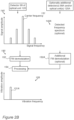
- System 100 comprises at least one shifter 130 such as at least one frequency shifter 132 and/or at least one phase shifter 134, configured to shift the frequency of at least one of coherent light sources 95 according to predetermined shifting characteristics, and processing unit 150 is configured to derive vibration frequency 131A of target 91 from a relation between sensor signal 140 and the predetermined shifting characteristics.
- the configuration of shifter(s) 130 to determine carrier frequency f c is shown schematically in Figure 2A by an arrow, near interference pattern 92.
- shifter(s) 130 may comprise at least one RF (radiofrequency) shifter 132 configured to shift an illumination frequency of one or more phase-correlated or possibly phase-locked coherent light source(s) 95 by a predetermined RF frequency 131.
- the vibration frequency may then be derived from a component 133 in sensor signal 140 at a frequency that is shifted from predetermined RF frequency 131.
- shifter(s) 130 may comprise at least one phase shifter 134 configured to shift a phase of one or more coherent light source(s) 95 by a predetermined phase shift pattern.
- the vibration frequency may then be derived from a relation between sensor signal 140 and the predetermined phase shift pattern.
- Figure 3 is an exemplary illustration of interference patterns 92 in simulation 92A and in experiment 92B, according to some embodiments of the invention.
- Mask 122 is illustrated schematically as having parallel straight lines, and interference patterns 92 are shown as derived from simulation 92A and from experiments 92B in an exemplary manner.
- Speckle pattern 90A is transformed through the use of two illumination sources 95 and interference pattern of the respective reflected radiation, into modulated line patterns which are then focused on detector 99 through mask 122.
- speckle pattern 90A is expressed in the disturbances in interference pattern and do not convey the information concerning the vibrations of the target.
- embodiments with interference patterns may use modulation of illumination sources 95 to enable isolation of a signal proportional to the vibration intensity of target 91, as explained below.
- FIGS 4A-4D are high level block diagrams of illumination sources 95, according to some embodiments of the invention.
- multiple illumination sources 95 may be implemented using a single illumination source 97 which is split (by a splitter 97A ) into two or more illumination sources 95A, 95B by a beam splitter 97A, with shifter(s) 130 implemented as one or more phase shifter(s) 134, acousto-optic deflector(s) (AOD) 136A, 136B and/or other optical components, illumination sources 95A, 95B may be configured to provide spots 96A, 96B with specified characteristics of target 91.
- illumination sources 95 may comprise two lasers amplifiers 137A, 137B configured to receive the outputs of AODs 136A, 136B and be phase-locked with laser seeder 97. Illumination from lasers amplifiers 137A, 137B may then be combined by a combiner 138, collimated by a collimator 139 and used as illumination sources 95A, 95B to provide spots 96A, 96B.
- both AODs 136A, 136B may be located on one split channel. Elements from Figures 4A-4D may be combined to form additional embodiments.
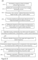
- Method 200 may comprise focusing, onto a sensor and through a mask, interfered scattered illumination from the spots on the target, to yield a signal (stage 225), shifting a frequency and/or a phase of at least one of the coherent light sources to provide a carrier frequency in the signal (stage 230 ) and deriving a vibration frequency of the target from the sensor signal with respect to the carrier frequency (stage 250 ), e.g., from a component in the sensor signal at a frequency that is shifted from the carrier frequency (stage 252 ), as illustrated e.g., in Figures 2A and 2B and in the accompanying description.
- method 200 may comprise illuminating the target with one (or more) illumination source(s) (stage 210 ), focusing, onto the sensor, scattered illumination from the target through the mask, to yield a signal (stage 220 ), moving, mechanically, the mask across the aperture, according to predetermined characteristics, to yield a carrier frequency (stage 240 ) and deriving a vibration frequency of the target from an analysis of the sensor signal with respect to the carrier frequency (stage 250 ) as illustrated e.g., in Figure 1 and the accompanying description.
- the mask parameters and movement parameters, as well as illumination and focusing parameters may be optimized with respect to the expected speckle patterns as described above.
- an embodiment is an example or implementation of the invention.
- the various appearances of "one embodiment”, “an embodiment”, “certain embodiments” or “some embodiments” do not necessarily all refer to the same embodiments.
- various features of the invention may be described in the context of a single embodiment, the features may also be provided separately or in any suitable combination.
- the invention may also be implemented in a single embodiment.
- Certain embodiments of the invention may include features from different embodiments disclosed above, and certain embodiments may incorporate elements from other embodiments disclosed above.
- the disclosure of elements of the invention in the context of a specific embodiment is not to be taken as limiting their use in the specific embodiment alone.
- the invention can be carried out or practiced in various ways and that the invention can be implemented in certain embodiments other than the ones outlined in the description above.
Landscapes
- Physics & Mathematics (AREA)
- General Physics & Mathematics (AREA)
- Length Measuring Devices By Optical Means (AREA)
- Instruments For Measurement Of Length By Optical Means (AREA)
- Measuring Volume Flow (AREA)
Claims (11)
- System zum Erfassen von Schwingungen (100), umfassend:mindestens zwei kohärente Lichtquellen (95) mit bekannten Phasenbeziehungen zwischen ihnen, die dazu konfiguriert sind, ein Ziel (91) mit mindestens zwei entsprechenden Punkten (96) zu beleuchten,einen Sensor (99) mit einem oder mehreren Pixeln, der dazu konfiguriert ist, interferierte Streubeleuchtung von den Punkten auf dem Ziel zu detektieren,eine optische Einheit (120), die eine Apertur, an der Streustrahlung interferiert, um ein Interferenzmuster zu bilden, und eine Maske (122) umfasst, wobei die optische Einheit dazu konfiguriert ist, die interferierte Streubeleuchtung von den Punkten auf dem Ziel, die durch die Apertur und die Maske hindurchgeht, auf den Sensor zu fokussieren, um ein Signal (140) zu ergeben, welches das Interferenzmuster anzeigt,mindestens einen Schieber (132), der dazu konfiguriert ist, eine Frequenz von mindestens einer der kohärenten Lichtquellen in Bezug auf die anderen kohärenten Lichtquellen gemäß vorbestimmten Verschiebungscharakteristiken zu verschieben, um eine Trägerfrequenz (131) in dem Signal bereitzustellen, undeine Verarbeitungseinheit (150), die dazu konfiguriert ist, eine Schwingungsfrequenz (131A) des Ziels aus einer Beziehung zwischen dem Signal (140) und den vorbestimmten Verschiebungscharakteristiken abzuleiten.
- System nach Anspruch 1, wobei der mindestens eine Schieber (134) konfiguriert ist, um eine Phase der mindestens einen der kohärenten Lichtquellen (95) zu verschieben.
- System nach Anspruch 1, wobei die mindestens zwei kohärenten Lichtquellen von einer einzigen Beleuchtungsquelle (97) aufgeteilt sind (97A).
- System nach Anspruch 1, wobei die optische Einheit (120) dazu konfiguriert ist, das Signal in Bezug auf unterschiedliche Polarisationen der interferierten Streubeleuchtung zu erzeugen.
- System nach Anspruch 1, wobei die Maske (122) in Bezug auf ein erwartetes Interferenzmuster der Streubeleuchtung konfiguriert ist.
- Verfahren zum Erfassen von Schwingungen (200), umfassend:Beleuchten eines Ziels durch mindestens zwei kohärente Lichtquellen mit bekannten Phasenbeziehungen zwischen ihnen, um mindestens zwei entsprechende Punkte (210) zu bilden,Detektieren von interferierter Streubeleuchtung von den Punkten auf dem Ziel unter Verwendung eines Sensors,Fokussieren der interferierten Streubeleuchtung von den Punkten auf dem Ziel auf den Sensor über eine Apertur, an der Streustrahlung interferiert, um ein Interferenzmuster zu bilden, und durch eine Maske hindurch, um ein Signal zu ergeben, welches das Interferenzmuster (220) anzeigt,Verschieben einer Frequenz von mindestens einer der kohärenten Lichtquellen in Bezug auf die anderen kohärenten Lichtquellen gemäß vorbestimmten Verschiebungscharakteristiken, um eine Trägerfrequenz in dem Signal (230) bereitzustellen, undAbleiten einer Schwingungsfrequenz des Ziels aus einer Beziehung zwischen dem Signal und den vorbestimmten Verschiebungscharakteristiken (250).
- Verfahren nach Anspruch 6, wobei das Verschieben ein Verschieben einer Phase der mindestens einen der kohärenten Lichtquellen umfasst.
- Verfahren nach Anspruch 6, ferner umfassend ein Teilen der mindestens zwei kohärenten Lichtquellen von einer einzigen Beleuchtungsquelle (212).
- Verfahren nach Anspruch 6, ferner umfassend ein Erzeugen des Signals in Bezug auf unterschiedliche Polarisationen der interferierten Streubeleuchtung (262).
- Verfahren nach Anspruch 6, ferner umfassend ein Konfigurieren der Maske in Bezug auf ein erwartetes Interferenzmuster der Streubeleuchtung.
- Verfahren nach Anspruch 6, ferner umfassend ein Optimieren von Größen und Abständen der Punkte in Bezug auf Maskenparameter (260).
Applications Claiming Priority (2)
| Application Number | Priority Date | Filing Date | Title |
|---|---|---|---|
| IL248274A IL248274B (en) | 2016-10-09 | 2016-10-09 | Optical remote sensing of vibrations |
| PCT/IL2017/051116 WO2018065982A1 (en) | 2016-10-09 | 2017-10-02 | Optical remote sensing of vibrations |
Publications (4)
| Publication Number | Publication Date |
|---|---|
| EP3523613A1 EP3523613A1 (de) | 2019-08-14 |
| EP3523613A4 EP3523613A4 (de) | 2020-09-23 |
| EP3523613B1 true EP3523613B1 (de) | 2023-06-14 |
| EP3523613C0 EP3523613C0 (de) | 2023-06-14 |
Family
ID=61830887
Family Applications (1)
| Application Number | Title | Priority Date | Filing Date |
|---|---|---|---|
| EP17857973.6A Active EP3523613B1 (de) | 2016-10-09 | 2017-10-02 | Optische fernerfassung von schwingungen |
Country Status (5)
| Country | Link |
|---|---|
| US (1) | US10697823B2 (de) |
| EP (1) | EP3523613B1 (de) |
| IL (1) | IL248274B (de) |
| SG (1) | SG11201902957RA (de) |
| WO (1) | WO2018065982A1 (de) |
Families Citing this family (3)
| Publication number | Priority date | Publication date | Assignee | Title |
|---|---|---|---|---|
| EP3779378B1 (de) * | 2018-04-05 | 2022-05-11 | Shimadzu Corporation | Schwingungsmesser |
| WO2020110197A1 (ja) * | 2018-11-27 | 2020-06-04 | 株式会社島津製作所 | 欠陥検査装置および欠陥検査方法 |
| CN113175867B (zh) * | 2021-05-24 | 2022-07-26 | 浙江理工大学 | 一种正弦相位调制激光干涉仪及载波生成、信号解调方法 |
Family Cites Families (4)
| Publication number | Priority date | Publication date | Assignee | Title |
|---|---|---|---|---|
| US3782176A (en) * | 1972-03-30 | 1974-01-01 | Gen Electric | Apparatus for measuring vibration in a moving object |
| US5838439A (en) * | 1997-03-14 | 1998-11-17 | Zang; De Yu | Heterodyned self-mixing laser diode vibrometer |
| US6972846B2 (en) * | 2003-03-31 | 2005-12-06 | Metrolaser, Inc. | Multi-beam heterodyne laser doppler vibrometer |
| US11371878B2 (en) * | 2016-08-29 | 2022-06-28 | Elbit Systems Land And C4I Ltd. | Optical detection of vibrations |
-
2016
- 2016-10-09 IL IL248274A patent/IL248274B/en active IP Right Grant
-
2017
- 2017-10-02 SG SG11201902957RA patent/SG11201902957RA/en unknown
- 2017-10-02 US US16/338,500 patent/US10697823B2/en active Active
- 2017-10-02 WO PCT/IL2017/051116 patent/WO2018065982A1/en not_active Ceased
- 2017-10-02 EP EP17857973.6A patent/EP3523613B1/de active Active
Non-Patent Citations (1)
| Title |
|---|
| VEBER A A ET AL: "Laser vibrometry based on analysis of the speckle pattern from a remote object", APPLIED PHYSICS B ; LASERS AND OPTICS, SPRINGER, BERLIN, DE, vol. 105, no. 3, 4 June 2011 (2011-06-04), pages 613 - 617, XP019974756, ISSN: 1432-0649, DOI: 10.1007/S00340-011-4585-1 * |
Also Published As
| Publication number | Publication date |
|---|---|
| WO2018065982A1 (en) | 2018-04-12 |
| IL248274A0 (en) | 2017-03-30 |
| EP3523613C0 (de) | 2023-06-14 |
| EP3523613A1 (de) | 2019-08-14 |
| US20190339117A1 (en) | 2019-11-07 |
| IL248274B (en) | 2018-06-28 |
| SG11201902957RA (en) | 2019-05-30 |
| US10697823B2 (en) | 2020-06-30 |
| EP3523613A4 (de) | 2020-09-23 |
Similar Documents
| Publication | Publication Date | Title |
|---|---|---|
| US6972846B2 (en) | Multi-beam heterodyne laser doppler vibrometer | |
| EP3326152B1 (de) | Differentieller interferometrischer sensor mit mehrstrahligem laser und verfahren zur vibrationsbildgebung | |
| US10261187B2 (en) | Optical phasograms for LADAR vibrometry | |
| US9772238B2 (en) | Real-time fiber optic interferometry controller | |
| US7477398B2 (en) | Multi-beam heterodyne laser doppler vibrometer | |
| US7193720B2 (en) | Optical vibration imager | |
| US9651477B1 (en) | Method and apparatus for simultaneous observation of three-degrees of vibrational freedom using single heterodyne beam | |
| AU2007250514B2 (en) | Remote sensing of underwater acoustic fields | |
| KR20190099329A (ko) | 광학 위상-엔코드된 거리 검출의 도플러 검출과 도플러 보정을 위한 방법과 시스템 | |
| WO2017187510A1 (ja) | 距離計測装置、距離計測方法、及び形状計測装置 | |
| Aranchuk et al. | Multi-beam laser Doppler vibrometer for landmine detection | |
| JP2010203860A (ja) | 振動計測装置及び振動計測方法 | |
| Mallick et al. | A simple dual-beam time-multiplexed photon doppler velocimeter for pressure-shear plate impact experiments | |
| US10697823B2 (en) | Optical remote sensing of vibrations | |
| US4171159A (en) | Optical homodyne microscope | |
| AU2003227869A1 (en) | Method and apparatus for laser vibrometry | |
| US8717577B1 (en) | Compensating aperture for utilizing shearography from a moving platform | |
| IL286820A (en) | A method and system for mapping and measuring distance | |
| Aranchuk et al. | Laser multi-beam differential interferometric sensor for acoustic detection of buried objects | |
| Ren et al. | Complex moving target recognition based on optical phase-locked loop in LIDAR | |
| US10436570B1 (en) | High speed Michelson interferometer microscope | |
| AU2023415444A1 (en) | System and method for optical range and velocity detection | |
| WO2024142073A1 (en) | System and method for optical range doppler detection | |
| Perea et al. | Multi-axis heterodyne interferometric for simultaneous observation of 5 degrees of freedom using a single beam | |
| CN118190134A (zh) | 一种可抑制噪声的激光自混合测量系统及方法 |
Legal Events
| Date | Code | Title | Description |
|---|---|---|---|
| STAA | Information on the status of an ep patent application or granted ep patent |
Free format text: STATUS: THE INTERNATIONAL PUBLICATION HAS BEEN MADE |
|
| PUAI | Public reference made under article 153(3) epc to a published international application that has entered the european phase |
Free format text: ORIGINAL CODE: 0009012 |
|
| STAA | Information on the status of an ep patent application or granted ep patent |
Free format text: STATUS: REQUEST FOR EXAMINATION WAS MADE |
|
| 17P | Request for examination filed |
Effective date: 20190507 |
|
| AK | Designated contracting states |
Kind code of ref document: A1 Designated state(s): AL AT BE BG CH CY CZ DE DK EE ES FI FR GB GR HR HU IE IS IT LI LT LU LV MC MK MT NL NO PL PT RO RS SE SI SK SM TR |
|
| AX | Request for extension of the european patent |
Extension state: BA ME |
|
| RIN1 | Information on inventor provided before grant (corrected) |
Inventor name: LEV, ANER Inventor name: KARL, DAVID Inventor name: NUSSINSON, DAN |
|
| DAV | Request for validation of the european patent (deleted) | ||
| DAX | Request for extension of the european patent (deleted) | ||
| RIC1 | Information provided on ipc code assigned before grant |
Ipc: G01B 9/02 20060101ALI20200518BHEP Ipc: G01H 9/00 20060101AFI20200518BHEP |
|
| A4 | Supplementary search report drawn up and despatched |
Effective date: 20200826 |
|
| RIC1 | Information provided on ipc code assigned before grant |
Ipc: G01H 9/00 20060101AFI20200820BHEP Ipc: G01B 9/02 20060101ALI20200820BHEP |
|
| GRAP | Despatch of communication of intention to grant a patent |
Free format text: ORIGINAL CODE: EPIDOSNIGR1 |
|
| STAA | Information on the status of an ep patent application or granted ep patent |
Free format text: STATUS: GRANT OF PATENT IS INTENDED |
|
| INTG | Intention to grant announced |
Effective date: 20230131 |
|
| RAP3 | Party data changed (applicant data changed or rights of an application transferred) |
Owner name: SOREQ NUCLEAR RESEARCH CENTER Owner name: ELBIT SYSTEMS LAND AND C4I LTD. |
|
| GRAS | Grant fee paid |
Free format text: ORIGINAL CODE: EPIDOSNIGR3 |
|
| GRAA | (expected) grant |
Free format text: ORIGINAL CODE: 0009210 |
|
| STAA | Information on the status of an ep patent application or granted ep patent |
Free format text: STATUS: THE PATENT HAS BEEN GRANTED |
|
| AK | Designated contracting states |
Kind code of ref document: B1 Designated state(s): AL AT BE BG CH CY CZ DE DK EE ES FI FR GB GR HR HU IE IS IT LI LT LU LV MC MK MT NL NO PL PT RO RS SE SI SK SM TR |
|
| REG | Reference to a national code |
Ref country code: CH Ref legal event code: EP |
|
| REG | Reference to a national code |
Ref country code: DE Ref legal event code: R096 Ref document number: 602017070294 Country of ref document: DE |
|
| REG | Reference to a national code |
Ref country code: AT Ref legal event code: REF Ref document number: 1579549 Country of ref document: AT Kind code of ref document: T Effective date: 20230715 |
|
| U01 | Request for unitary effect filed |
Effective date: 20230707 |
|
| U07 | Unitary effect registered |
Designated state(s): AT BE BG DE DK EE FI FR IT LT LU LV MT NL PT SE SI Effective date: 20230719 |
|
| REG | Reference to a national code |
Ref country code: LT Ref legal event code: MG9D |
|
| U20 | Renewal fee for the european patent with unitary effect paid |
Year of fee payment: 7 Effective date: 20230905 |
|
| PG25 | Lapsed in a contracting state [announced via postgrant information from national office to epo] |
Ref country code: NO Free format text: LAPSE BECAUSE OF FAILURE TO SUBMIT A TRANSLATION OF THE DESCRIPTION OR TO PAY THE FEE WITHIN THE PRESCRIBED TIME-LIMIT Effective date: 20230914 Ref country code: ES Free format text: LAPSE BECAUSE OF FAILURE TO SUBMIT A TRANSLATION OF THE DESCRIPTION OR TO PAY THE FEE WITHIN THE PRESCRIBED TIME-LIMIT Effective date: 20230614 |
|
| PG25 | Lapsed in a contracting state [announced via postgrant information from national office to epo] |
Ref country code: RS Free format text: LAPSE BECAUSE OF FAILURE TO SUBMIT A TRANSLATION OF THE DESCRIPTION OR TO PAY THE FEE WITHIN THE PRESCRIBED TIME-LIMIT Effective date: 20230614 Ref country code: HR Free format text: LAPSE BECAUSE OF FAILURE TO SUBMIT A TRANSLATION OF THE DESCRIPTION OR TO PAY THE FEE WITHIN THE PRESCRIBED TIME-LIMIT Effective date: 20230614 Ref country code: GR Free format text: LAPSE BECAUSE OF FAILURE TO SUBMIT A TRANSLATION OF THE DESCRIPTION OR TO PAY THE FEE WITHIN THE PRESCRIBED TIME-LIMIT Effective date: 20230915 |
|
| PG25 | Lapsed in a contracting state [announced via postgrant information from national office to epo] |
Ref country code: SK Free format text: LAPSE BECAUSE OF FAILURE TO SUBMIT A TRANSLATION OF THE DESCRIPTION OR TO PAY THE FEE WITHIN THE PRESCRIBED TIME-LIMIT Effective date: 20230614 |
|
| PG25 | Lapsed in a contracting state [announced via postgrant information from national office to epo] |
Ref country code: IS Free format text: LAPSE BECAUSE OF FAILURE TO SUBMIT A TRANSLATION OF THE DESCRIPTION OR TO PAY THE FEE WITHIN THE PRESCRIBED TIME-LIMIT Effective date: 20231014 |
|
| PG25 | Lapsed in a contracting state [announced via postgrant information from national office to epo] |
Ref country code: SM Free format text: LAPSE BECAUSE OF FAILURE TO SUBMIT A TRANSLATION OF THE DESCRIPTION OR TO PAY THE FEE WITHIN THE PRESCRIBED TIME-LIMIT Effective date: 20230614 Ref country code: SK Free format text: LAPSE BECAUSE OF FAILURE TO SUBMIT A TRANSLATION OF THE DESCRIPTION OR TO PAY THE FEE WITHIN THE PRESCRIBED TIME-LIMIT Effective date: 20230614 Ref country code: RO Free format text: LAPSE BECAUSE OF FAILURE TO SUBMIT A TRANSLATION OF THE DESCRIPTION OR TO PAY THE FEE WITHIN THE PRESCRIBED TIME-LIMIT Effective date: 20230614 Ref country code: IS Free format text: LAPSE BECAUSE OF FAILURE TO SUBMIT A TRANSLATION OF THE DESCRIPTION OR TO PAY THE FEE WITHIN THE PRESCRIBED TIME-LIMIT Effective date: 20231014 Ref country code: CZ Free format text: LAPSE BECAUSE OF FAILURE TO SUBMIT A TRANSLATION OF THE DESCRIPTION OR TO PAY THE FEE WITHIN THE PRESCRIBED TIME-LIMIT Effective date: 20230614 |
|
| PG25 | Lapsed in a contracting state [announced via postgrant information from national office to epo] |
Ref country code: PL Free format text: LAPSE BECAUSE OF FAILURE TO SUBMIT A TRANSLATION OF THE DESCRIPTION OR TO PAY THE FEE WITHIN THE PRESCRIBED TIME-LIMIT Effective date: 20230614 |
|
| REG | Reference to a national code |
Ref country code: DE Ref legal event code: R097 Ref document number: 602017070294 Country of ref document: DE |
|
| PLBE | No opposition filed within time limit |
Free format text: ORIGINAL CODE: 0009261 |
|
| STAA | Information on the status of an ep patent application or granted ep patent |
Free format text: STATUS: NO OPPOSITION FILED WITHIN TIME LIMIT |
|
| 26N | No opposition filed |
Effective date: 20240315 |
|
| PG25 | Lapsed in a contracting state [announced via postgrant information from national office to epo] |
Ref country code: MC Free format text: LAPSE BECAUSE OF FAILURE TO SUBMIT A TRANSLATION OF THE DESCRIPTION OR TO PAY THE FEE WITHIN THE PRESCRIBED TIME-LIMIT Effective date: 20230614 |
|
| REG | Reference to a national code |
Ref country code: CH Ref legal event code: PL |
|
| PG25 | Lapsed in a contracting state [announced via postgrant information from national office to epo] |
Ref country code: CH Free format text: LAPSE BECAUSE OF NON-PAYMENT OF DUE FEES Effective date: 20231031 |
|
| PG25 | Lapsed in a contracting state [announced via postgrant information from national office to epo] |
Ref country code: CH Free format text: LAPSE BECAUSE OF NON-PAYMENT OF DUE FEES Effective date: 20231031 |
|
| PG25 | Lapsed in a contracting state [announced via postgrant information from national office to epo] |
Ref country code: IE Free format text: LAPSE BECAUSE OF NON-PAYMENT OF DUE FEES Effective date: 20231002 |
|
| U20 | Renewal fee for the european patent with unitary effect paid |
Year of fee payment: 8 Effective date: 20240906 |
|
| PG25 | Lapsed in a contracting state [announced via postgrant information from national office to epo] |
Ref country code: IE Free format text: LAPSE BECAUSE OF NON-PAYMENT OF DUE FEES Effective date: 20231002 |
|
| PG25 | Lapsed in a contracting state [announced via postgrant information from national office to epo] |
Ref country code: CY Free format text: LAPSE BECAUSE OF FAILURE TO SUBMIT A TRANSLATION OF THE DESCRIPTION OR TO PAY THE FEE WITHIN THE PRESCRIBED TIME-LIMIT; INVALID AB INITIO Effective date: 20171002 |
|
| PG25 | Lapsed in a contracting state [announced via postgrant information from national office to epo] |
Ref country code: HU Free format text: LAPSE BECAUSE OF FAILURE TO SUBMIT A TRANSLATION OF THE DESCRIPTION OR TO PAY THE FEE WITHIN THE PRESCRIBED TIME-LIMIT; INVALID AB INITIO Effective date: 20171002 |
|
| U20 | Renewal fee for the european patent with unitary effect paid |
Year of fee payment: 9 Effective date: 20250909 |
|
| PGFP | Annual fee paid to national office [announced via postgrant information from national office to epo] |
Ref country code: GB Payment date: 20250904 Year of fee payment: 9 |
|
| PG25 | Lapsed in a contracting state [announced via postgrant information from national office to epo] |
Ref country code: TR Free format text: LAPSE BECAUSE OF FAILURE TO SUBMIT A TRANSLATION OF THE DESCRIPTION OR TO PAY THE FEE WITHIN THE PRESCRIBED TIME-LIMIT Effective date: 20230614 |