EP3523522B1 - Bandklemmenisoliersystem - Google Patents
Bandklemmenisoliersystem Download PDFInfo
- Publication number
- EP3523522B1 EP3523522B1 EP17859092.3A EP17859092A EP3523522B1 EP 3523522 B1 EP3523522 B1 EP 3523522B1 EP 17859092 A EP17859092 A EP 17859092A EP 3523522 B1 EP3523522 B1 EP 3523522B1
- Authority
- EP
- European Patent Office
- Prior art keywords
- hollow tubular
- band clamp
- securing
- insulation
- elongate member
- Prior art date
- Legal status (The legal status is an assumption and is not a legal conclusion. Google has not performed a legal analysis and makes no representation as to the accuracy of the status listed.)
- Active
Links
Images


Classifications
-
- F—MECHANICAL ENGINEERING; LIGHTING; HEATING; WEAPONS; BLASTING
- F16—ENGINEERING ELEMENTS AND UNITS; GENERAL MEASURES FOR PRODUCING AND MAINTAINING EFFECTIVE FUNCTIONING OF MACHINES OR INSTALLATIONS; THERMAL INSULATION IN GENERAL
- F16L—PIPES; JOINTS OR FITTINGS FOR PIPES; SUPPORTS FOR PIPES, CABLES OR PROTECTIVE TUBING; MEANS FOR THERMAL INSULATION IN GENERAL
- F16L59/00—Thermal insulation in general
- F16L59/14—Arrangements for the insulation of pipes or pipe systems
- F16L59/16—Arrangements specially adapted to local requirements at flanges, junctions, valves or the like
- F16L59/21—Arrangements specially adapted to local requirements at flanges, junctions, valves or the like adapted for expansion-compensation devices
-
- F—MECHANICAL ENGINEERING; LIGHTING; HEATING; WEAPONS; BLASTING
- F16—ENGINEERING ELEMENTS AND UNITS; GENERAL MEASURES FOR PRODUCING AND MAINTAINING EFFECTIVE FUNCTIONING OF MACHINES OR INSTALLATIONS; THERMAL INSULATION IN GENERAL
- F16L—PIPES; JOINTS OR FITTINGS FOR PIPES; SUPPORTS FOR PIPES, CABLES OR PROTECTIVE TUBING; MEANS FOR THERMAL INSULATION IN GENERAL
- F16L13/00—Non-disconnectable pipe joints, e.g. soldered, adhesive, or caulked joints
- F16L13/02—Welded joints
- F16L13/0218—Welded joints having an inner or outer ring
- F16L13/0236—Welded joints having an inner or outer ring having an outer ring
-
- F—MECHANICAL ENGINEERING; LIGHTING; HEATING; WEAPONS; BLASTING
- F16—ENGINEERING ELEMENTS AND UNITS; GENERAL MEASURES FOR PRODUCING AND MAINTAINING EFFECTIVE FUNCTIONING OF MACHINES OR INSTALLATIONS; THERMAL INSULATION IN GENERAL
- F16L—PIPES; JOINTS OR FITTINGS FOR PIPES; SUPPORTS FOR PIPES, CABLES OR PROTECTIVE TUBING; MEANS FOR THERMAL INSULATION IN GENERAL
- F16L59/00—Thermal insulation in general
- F16L59/02—Shape or form of insulating materials, with or without coverings integral with the insulating materials
- F16L59/028—Compositions for or methods of fixing a thermally insulating material
-
- F—MECHANICAL ENGINEERING; LIGHTING; HEATING; WEAPONS; BLASTING
- F01—MACHINES OR ENGINES IN GENERAL; ENGINE PLANTS IN GENERAL; STEAM ENGINES
- F01N—GAS-FLOW SILENCERS OR EXHAUST APPARATUS FOR MACHINES OR ENGINES IN GENERAL; GAS-FLOW SILENCERS OR EXHAUST APPARATUS FOR INTERNAL-COMBUSTION ENGINES
- F01N13/00—Exhaust or silencing apparatus characterised by constructional features
- F01N13/18—Construction facilitating manufacture, assembly, or disassembly
- F01N13/1838—Construction facilitating manufacture, assembly, or disassembly characterised by the type of connection between parts of exhaust or silencing apparatus, e.g. between housing and tubes, between tubes and baffles
- F01N13/1844—Mechanical joints
-
- F—MECHANICAL ENGINEERING; LIGHTING; HEATING; WEAPONS; BLASTING
- F01—MACHINES OR ENGINES IN GENERAL; ENGINE PLANTS IN GENERAL; STEAM ENGINES
- F01N—GAS-FLOW SILENCERS OR EXHAUST APPARATUS FOR MACHINES OR ENGINES IN GENERAL; GAS-FLOW SILENCERS OR EXHAUST APPARATUS FOR INTERNAL-COMBUSTION ENGINES
- F01N2450/00—Methods or apparatus for fitting, inserting or repairing different elements
- F01N2450/18—Methods or apparatus for fitting, inserting or repairing different elements by using quick-active type locking mechanisms, e.g. clips
Definitions
- Embodiments disclosed herein relate to insulation assemblies for pipes and ducts in general, and clamping apparatuses and methods in particular.
- US 4 093 282 A concerns a hose clamp utilizing two constricting band type hose clamps which are tied together by means of a strapping arrangement and includes one clamp which surrounds the hose itself and is provided with protuberances which press into the outer surface of the hose to provide a strong gripping function which prevents the hose from moving with respect to this clamp while at the same time engaging the hose in a nondestructive manner.
- the hose if not grippingly interengaged with the clamp would under pressure slide out of the clamp and off of the fitting.
- a second hose clamp is clamped about the rigid fitting to which the hose is attached at a point beyond an enlargement in the fitting, so that this clamp cannot move past the fitting enlargement.
- the present invention concerns a band clamp insulation assembly according to claim 1 and a method of providing insulation for a hollow tubular member according to claim 12. Further aspects of the present invention are defined in the dependent claims. Embodiments of the invention are directed to band clamp insulation assembly configured for insulating a hollow tubular member and reducing formation of gaps due to differential thermal expansion of the hollow tubular member and the insulation.
- the band clamp insulation assembly typically comprises: a securing member having a first elongate member, wherein a predetermined fixing portion of the securing member is configured to be affixed to the hollow tubular member; a band clamp member configured for securing an insulation cover between the band clamp member and the hollow tubular member, wherein the band clamp member comprises a second elongate member and a clamping member; and a coupling member configured for fastening the first elongate member affixed to the hollow tubular member and the second elongate member positioned around the hollow tubular member.
- the coupling member is configured to fasten the first elongate member transversely with the second elongate member.
- the coupling member further comprises: a first connector configured for receiving the second elongate member positioned around the hollow tubular member; and an adjacent second connector configured for receiving the first elongate member affixed to the hollow tubular member; wherein the first elongate member is oriented in a direction transverse to the second elongate member.
- the band clamp insulation assembly configured further comprises: a an insulation cover configured to be positioned around the hollow tubular member, wherein the securing member is configured to be positioned on an outer surface of the hollow tubular member, and wherein the band clamp member is configured to be positioned around the hollow tubular member
- the securing member is oriented in a direction substantially parallel to a longitudinal axis of the hollow tubular member.
- the coupling member further comprises: a first connector configured for receiving the second elongate member; and an adjacent second connector configured for receiving the first elongate member.
- the coupling member is positioned on the band clamp member with the second elongate member extending through the first connector.
- Some embodiments of the invention are directed to a method of providing insulation for a hollow tubular member, the method comprising: providing a hollow tubular member, the hollow tubular member defining a longitudinal axis; providing a securing member having a first elongate member; positioning the securing member on an outer surface of the hollow tubular member and, securing a predetermined portion of the securing member to the hollow tubular member; providing an insulation cover; positioning the insulation cover around the hollow tubular member such that the insulation cover overlaps at least a portion of the securing member; providing a band clamp coupling assembly comprising: a band clamp member comprising a second elongate member and a clamping member; and a coupling member configured for fastening the first elongate member affixed to the hollow tubular member and the second elongate member positioned around the hollow tubular member; wherein the second elongate member is inserted through the coupling member; positioning the band clamp coupling assembly around the hollow tubular member, the band clamp member
- securing the predetermined portion of the planar securing member to the hollow tubular member comprises spot welding the first elongate member to the hollow tubular member at the predetermined portion.
- the method further comprises: securing a predetermined portion of the securing member to the hollow tubular member such that a free flexible end portion of the first elongate member is formed adjacent the predetermined portion, the predetermined portion being located between the insulation cover and the free flexible end portion; positioning the band clamp coupling assembly around the hollow tubular member such that the coupling member is aligned with the free flexible end portion; and folding the free flexible end portion over the coupling member to secure the first elongate member.
- Piping and tubing systems for industrial, automotive, recreational vehicles, HVAC ducting and other applications typically involve transport of fluids.
- sleeves, covers or other similar elements are often provided over one or more portions of the pipes for thermal insulation of the pipe and/or the fluid transported therein, pipe protection, structural support and reinforcement of the pipe, and/or other purposes.
- These sleeves, covers, wraps or the like that are configured to be provided on the pipes are hereinafter referred to as "pipe insulation.”
- pipe insulation it is often crucial that the inner surface of the pipe insulation is positioned tightly, in a close fit, and/or without any gaps with the pipe surface to ensure that the sleeve remains in the desired position on the pipe and provides the required insulation or protection.
- conventional band clamps may be employed to secure the insulation onto the pipe.
- the deferring thermal expansion properties of the pipes and the pipe insulation causes unavoidable gaps between the insulation and the pipe thereby weakening the desired tight fit.
- heat transfer from hot exhaust gases may cause an increase in temperature of the pipe and the insulation.
- the metal having greater thermal expansion coefficients (for example, 2-10 times greater) in comparison with that of the composite insulation, the metal would expand much more than the insulation.
- the increased expansion of the metal of the exhaust pipe, and particularly the outer circumference may exert hoop and radial stresses on the insulation causing the insulation to stretch along with the pipe.
- the pipe, and consequently the insulation may return to their original dimensions once initial/ambient temperature and/or thermal equilibrium is restored.
- the repetitive/cyclic stresses on the composite insulation may irreversibly modify the structure and dimensions of the composite insulation, such that the insulation is not restored to its original state.
- gaps may be formed between the composite insulation and the pipe at one or more locations/portions along the outer surface of the pipe.
- gaps may cause the composite insulation to dislocate/slip along radial and/or axial directions of the pipe, adversely affecting the insulation and protection of the pipe by the composite insulation.
- this dislocation/slip may be exacerbated by the vibration and other operating conditions of the pipe, requiring the insulation to be replaced often.
- the present invention alleviates the aforementioned concerns and provides a novel band clamp insulation system for ensuring a tight insulation around the pipe during extended operation of the system, greatly prolonging the efficacy of the insulation.
- Embodiments of the present invention are directed to significantly reducing the frequency of occurrence and minimizing the dimensions of the gaps, thereby improving the functioning of the insulation for increased periods of time.
- the novel band clamp insulation of the present invention also works to preclude the dislocation of the insulation due to component vibration.
- the band clamp insulation system will now be described with respect to Figures 1-5 , illustrating various facets of the insulating system in accordance with some embodiments of the invention.
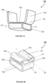
- Figure 1 illustrates a top view of the band clamp insulation system 100A, in accordance with some embodiments of the invention.
- Figure 1 illustrates an insulation system for a pipe 110.
- a "pipe” as used herein refers to a tubular elongate member with a predetermined cross-section, for example a hollow tube, pipe or hose.
- Figure 1 further illustrates one or more securing straps 120 or securing members 120 positioned/affixed along suitable locations on the pipe 110.
- the securing straps 120 are typically located on the pipe 110 at or proximate the ends of the portions 112 of the pipe 110 that are required to be insulated.
- multiple straps may be provided along the circumference of the pipe 110 (not illustrated) at suitable angular intervals (at every 30 degrees, 60 degrees or 90 degrees along the circumference).
- the securing strap 120 is a substantially planar elongate member defining a length L, a width W and a suitable thickness, which is configured to be flexible, pliable and/or configured for elastic/plastic deformation.
- the securing strap may comprise a quadrilateral contour as illustrated, or a suitable polygonal or curvilinear contour or a combination of the above.
- the securing strap 120 may also comprise perforations, slots or apertures of desired dimensions at predetermined locations.
- Figure 1 illustrates the securing strap 120 being affixed to the pipe 110 along a direction that is parallel to or substantially parallel to an axis of the pipe 110.
- the securing strap 120 is positioned such that the length L of the securing strap 120 extends along or is oriented parallel to or substantially parallel to the axis or longitudinal extent of the pipe 110. That said, in other embodiments, the securing strap 120 is oriented at a non-parallel angle with respect to the axis of the pipe 110. This securing angle may be chosen in the range of 0-90 degrees, for example, 20 degrees, 32 degrees or 45 degrees.
- the securing strap 120 is a metal strap made of a suitable grade of stainless steel, carbon steel, or another suitable metal or alloy.
- the thickness T (not illustrated) of the securing member 120 may be in the range of 0.001mm to 6mm (for example, 0.1mm to 0.6mm, 0.4mm to 0.7 mm, 0.2mm to 1.06mm, 0.1 mm to 2.5mm, 2mm to 3.6mm, or within, outside or overlapping these ranges), or in ranges of thickness T greater than 6mm (for example, 2.8mm to 6.3mm, 4.3mm to 9.5mm, 2.38mm to 12mm, or within, outside or overlapping these ranges).
- the securing strap 120 may be manufactured out of stainless steels, carbon steels, suitable metals like aluminum, brass, copper, tin, nickel, titanium, alloys, plastics, composites, natural or synthetic materials, polymers, and the like.
- the materials may be chosen based on their strength, disposition for plastic and elastic deformation without fracture, ductility/malleability, weight, rigidity/flexibility, operative temperature ranges, durability, resistance to fatigue and creep, magnetic properties and the like.
- the securing strap 120 is cut from a sheet metal.
- a predetermined portion 122 of the securing strap 120 is suitably fastened or affixed to the pipe 110, as illustrated by Figure 1 .
- the predetermined securing portion 12 defines free, unfastened portions with lengths L1 and L2 on either side, with portions L1, L2 and the predetermined securing portion 122 together forming the length L.
- the free portion L2 of the securing strap 120 may be located towards/proximate the portion 112 of the pipe 110 that is required to be insulated, while the opposite free portion L1 may be located away from portion 112.
- the lengths of the free portions L1 or L2 may be in a range of zero to L (for example, 0.2L, 0.5L, 0.65L and the like).
- the length L1 is typically greater than L2.
- the predetermined securing portion 122 is established (or the securing strap is fastened at 122) such that the free portion L1 is substantially three-fourths the length of the strap 120 or 0.75L.
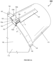
- FIG. 3A illustrates a front view of a band clamp 140 being coupled with the coupling member 130.
- Band clamps 140 typically comprise an elongate member or band 142 of a suitable length and width that is configured to surround/enclose an outer circumference of the pipe 110.
- the band clamp 140 further comprises a band securing member or clamping member 144 (illustrated in Figure 5 ) configured for securing the ends of the elongate member around the circumference of the pipe 110, such that the band clamp 140 applies a desired compression force (for example, radial and circumferential compression forces) on the pipe 110 thereby securing pipe insulation between itself and the pipe 110.
- a desired compression force for example, radial and circumferential compression forces
- Figure 4A illustrates a perspective view of the band clamp insulation system 100C, in accordance with some embodiments of the invention.
- Figure 4A illustrates a pipe 110 with the securing strap 120 being suitably affixed.
- Figure 4A further illustrates pipe insulation/composite insulation 150 provided around the predetermined portion 112 of the pipe 110, such that at least a portion of the length L1 of the securing strap 120 is not covered by the insulation 150.
- the insulation 150 may be trimmed at the edges to ensure uniform ends and/or to ensure that at least a portion of the length L1 of the securing strap 120 is not covered by the insulation 150.
- the coupling member 130 and band clamp 140 assembly 100B of Figures 3A and 3B is positioned/situated on the pipe 110 such that (i) the pipe insulation 150 is positioned between the elongate member 142 of the band clamp 140 and the outer surface of the pipe 110, and (ii) the coupling member is positioned proximate and/or aligned with the securing strap 120 and particularly its portion L1.
- the coupling member 130 is further linearly displaced or adjusted along the elongate member 140 to ensure the second connector 136 is aligned with the securing strap 120, after the clamp assembly is positioned on the pipe 110.
- the coupling member 130 is configured to secure two elongate members, i.e., the elongate member 142 of the band clamp 140 and the securing strap 120, the elongate member 142 and the securing strap 120 defining the first angle A between them. Furthermore, as illustrated by Figure 4A , the coupling member 130 is positioned on the elongate member 142 such that the second connector 136 is located adjacent the securing strap 120.
- the coupling member 130 and particularly the first connector 132 is plastically deformed and/or structurally modified to restrict/inhibit all relative motion or degrees of freedom between the coupling member 130 and the band clamp 140, thereby fixing the coupling member thereon.
- compressive force for example, by stamping or punching
- the one or more securing straps 120 around the circumference of the pipe 110 create eccentricity of the circumference (such as a substantially elliptical circumference), which aids in better securing the insulation around the pipe and/or reducing the adverse effects of differential thermal expansion.
- the clamping member 144 as used herein may be any device, tool, or fastener configured to hold or secure two or more elements together, either by mechanical, magnetic, and/or chemical means.
- the clamping member 144 is configured to hold, secure, fasten, or lock the ends of the elongate member together, either removably or permanently.
- the clamping member 144 is configured to secure the ends of the elongate member together, at a desired tension, such that the elongate member 142 forms a loop.
- the clamping member 144 is an embodiment of the coupling member 130 where the apertures 132d and 136d are aligned in parallel, while in other embodiments the clamping member may comprise a distinct structure.
- the clamping member 144 may comprise hose clamps, V-clamps, buckles, locking ties, loops, screw clips, worm drive clips, center punch clamps, spring clamps, wire clamps, ear clamps, strapping seals, cable ties, marman/marmon clamps, clasps, band clips, a combination of portions of the preceding non-limiting examples, or any other suitable clamping devices known in the art.
- the clamping member 144 is configured to secure the band clamp 140 around the pipe 110, such that a desired compression (for example, radial and circumferential compression forces) may be applied on the pipe 110 by changing the circumference/dimensions of the loop formed.
- the elongate member 142 and/or the clamping member 144 may be manufactured as multiple components that are then assembled together or the elongate member 142 and the clamping member 144 may be constructed as a single unit.
- the elongate member 142 and/or the clamping member 144 may be manufactured out of same or different materials, such as suitable grades of stainless steel, carbon steels, suitable metals like aluminum, brass, copper, tin, nickel, titanium, alloys, plastics, composites, natural or synthetic materials, polymers, and the like.
- the pipe 110 along with the insulation 150 and the clamping system (120, 130, and 140) may be subjected to heat treatment and subsequent cooling, such that the insulating material 150 is at least partially molded to the pipe or such that the insulating material hardens around the pipe 110 forming a rigid composite insulation cover/sleeve.
Landscapes
- Engineering & Computer Science (AREA)
- General Engineering & Computer Science (AREA)
- Mechanical Engineering (AREA)
- Clamps And Clips (AREA)
- Thermal Insulation (AREA)
Claims (14)
- Bandklemmen-Isolieranordnung (100A-100D), die für ein hohles rohrförmiges Element (110) konfiguriert ist und die Bildung von Lücken aufgrund unterschiedlicher Wärmeausdehnung des hohlen rohrförmigen Elements (110) und einer Isolierung vermindert, dadurch gekennzeichnet, dass die Anordnung umfasst:ein Befestigungselement (120) mit einem ersten länglichen Element, wobei ein vorbestimmter Befestigungsabschnitt (122) des Befestigungselements (120) so konfiguriert ist, dass er an dem hohlen rohrförmigen Element (110) befestigt werden kann;ein Bandklemmenelement (140), das zum Befestigen einer Isolierabdeckung zwischen dem Bandklemmenelement (140) und dem hohlen rohrförmigen Element (110) konfiguriert ist, wobei das Bandklemmenelement (140) ein zweites längliches Element (142) und ein Klemmelement umfasst; undein Kopplungselement (130), das so konfiguriert ist, dass es das erste längliche Element, das an dem hohlen rohrförmigen Element (110) befestigt ist, und das zweite längliche Element (142), das um das hohle rohrförmige Element (110) herum angeordnet ist, befestigt, wobeidas Kupplungselement (130) einen ersten Verbinder (132), der zur Aufnahme des zweiten länglichen Elements (142) konfiguriert ist, und einen benachbarten zweiten Verbinder (136), der zur Aufnahme des ersten länglichen Elements konfiguriert ist, umfasst.
- Bandklemmen-Isolieranordnung nach Anspruch 1, wobei das Verbindungselement (130) so konfiguriert ist, dass es das erste längliche Element und das zweite längliche Element (142) in einem ersten Winkel zwischen 0 Grad und 90 Grad befestigt.
- Bandklemmen-Isolieranordnung nach Anspruch 1, wobei das Verbindungselement (130) so konfiguriert ist, dass es das erste längliche Element quer mit dem zweiten länglichen Element (142) verbindet.
- Bandklemmen-Isolieranordnung nach Anspruch 1, wobei das erste längliche Element in einer Richtung quer zu dem zweiten länglichen Element (142) ausgerichtet ist und wobei das Kopplungselement (130) so strukturiert ist, dass es sich beim Zusammenbau entlang des ersten länglichen Elements, das an dem hohlen rohrförmigen Element (110) befestigt ist, relativ bewegt.
- Bandklemmen-Isolieranordnung nach Anspruch 1, wobei der zweite Verbinder (136) einen zentralen Abschnitt (136a), der an dem ersten Verbinder (132) befestigt ist, und zwei flexible freie Abschnitte (136b, 136c) auf beiden Seiten des zentralen Abschnitts (136a) umfasst.
- Bandklemmen-Isolieranordnung nach Anspruch 5, wobei die beiden flexiblen freien Abschnitte (136b, 136c) so gestaltet sind, dass sie über den zentralen Abschnitt (136a) gefaltet werden können, um das erste längliche Element zu befestigen.
- Bandklemmen-Isolieranordnung nach Anspruch 1, wobei das Befestigungselement (120) einen flexiblen freien Abschnitt angrenzend an den vorbestimmten Befestigungsabschnitt (122) umfasst, wobei das Kopplungselement (130) so konfiguriert ist, dass es den flexiblen freien Abschnitt aufnimmt, der über den vorbestimmten Befestigungsabschnitt (122) gefaltet ist.
- Bandklemmen-Isolieranordnung (100A-100D) nach Anspruch 1, wobei die Bandklemmen-Isolieranordnung ferner umfasst:eine Isolierabdeckung, die so konfiguriert ist, dass sie um das hohle rohrförmige Element (110) positioniert werden kann;wobei das Befestigungselement (120) so konfiguriert ist, dass es auf einer Außenfläche des hohlen rohrförmigen Elements (110) positioniert werden kann; undwobei das Bandklemmenelement (140) so konfiguriert ist, dass es um das hohle rohrförmige Element (110) herum positioniert wird.
- Bandklemmen-Isolieranordnung nach Anspruch 8, wobei das Befestigungselement (120) in einer Richtung im Wesentlichen parallel zu einer Längsachse des hohlen rohrförmigen Elements (110) ausgerichtet ist.
- Bandklemmen-Isolieranordnung nach Anspruch 8, wobei das Kupplungselement (130) so strukturiert ist, dass es sich beim Zusammenbau entlang des ersten länglichen Elements, das an dem hohlen rohrförmigen Element (110) befestigt ist, relativ bewegt.
- Bandklemmen-Isolieranordnung nach Anspruch 8, wobei das Kupplungselement (130) auf dem Bandklemmenelement (140) positioniert ist und sich das zweite längliche Element (142) durch den ersten Verbinder (132) erstreckt.
- Verfahren zum Bereitstellen einer Isolierung für ein hohles rohrförmiges Element (110), dadurch gekennzeichnet, dass das Verfahren umfasst:Bereitstellen eines hohlen rohrförmigen Elements (110), wobei das hohle rohrförmige Element (110) eine Längsachse definiert;Bereitstellen eines Befestigungselements (120) mit einem ersten länglichen Element;Positionieren des Befestigungselements (120) auf einer Außenfläche des hohlen rohrförmigen Elements (110) und Befestigen eines vorbestimmten Abschnitts des Befestigungselements (120) an dem hohlen rohrförmigen Element (110);Bereitstellen einer Isolierabdeckung;Positionieren der Isolierabdeckung um das hohle rohrförmige Element (110), so dass die Isolierabdeckung mindestens einen Teil des Befestigungselements (120) überlappt;Bereitstellen einer Bandklemm-Kupplungsanordnung, die umfasst:ein Bandklemmenelement (140), das ein zweites längliches Element (142) und ein Klemmelement umfasst; undein Kopplungselement (130), das zum Befestigen des ersten länglichen Elements, das an dem hohlen rohrförmigen Element (110) befestigt ist, und des zweiten länglichen Elements (142), das um das hohle rohrförmige Element (110) herum positioniert ist, konfiguriert ist, wobei das Kopplungselement (130) einen ersten Verbinder (132), der zum Aufnehmen des zweiten länglichen Elements (142) konfiguriert ist, und einen benachbarten zweiten Verbinder (136), der zum Aufnehmen des ersten länglichen Elements konfiguriert ist, umfasst;wobei das zweite längliche Element (142) durch das Kupplungselement (130) eingeführt wird;Positionieren der Bandklemmen- Kupplungsanordnung um das hohle rohrförmige Element (110), wobei das Bandklemmenelement (140) die Isolierabdeckung zwischen dem Bandklemmenelement (140) und dem hohlen rohrförmigen Element (110) sichert.
- Verfahren nach Anspruch 12, wobei das Befestigen des vorbestimmten Abschnitts des Befestigungselements (120) an dem hohlen rohrförmigen Element (110) Punktschweißen des ersten länglichen Elements an dem hohlen rohrförmigen Element (110) an dem vorbestimmten Abschnitt umfasst.
- Verfahren nach Anspruch 12, wobei das Verfahren ferner umfasst:Befestigen eines vorbestimmten Abschnitts des Befestigungselements (120) an dem hohlen rohrförmigen Element (110), so dass ein freier flexibler Endabschnitt des ersten länglichen Elements angrenzend an den vorbestimmten Abschnitt gebildet wird, wobei sich der vorbestimmte Abschnitt zwischen der Isolierabdeckung und dem freien flexiblen Endabschnitt befindet;Positionieren der Bandklemmen-Kupplungsanordnung um das hohle rohrförmige Element (110), so dass das Kupplungselement (130) mit dem freien flexiblen Endabschnitt ausgerichtet ist; undFalten des freien flexiblen Endabschnitts über das Kupplungselement (130), um das erste längliche Element zu befestigen.
Applications Claiming Priority (2)
| Application Number | Priority Date | Filing Date | Title |
|---|---|---|---|
| US201662404047P | 2016-10-04 | 2016-10-04 | |
| PCT/US2017/055081 WO2018067665A1 (en) | 2016-10-04 | 2017-10-04 | Band clamp insulation system |
Publications (3)
| Publication Number | Publication Date |
|---|---|
| EP3523522A1 EP3523522A1 (de) | 2019-08-14 |
| EP3523522A4 EP3523522A4 (de) | 2020-07-29 |
| EP3523522B1 true EP3523522B1 (de) | 2023-12-20 |
Family
ID=61832113
Family Applications (1)
| Application Number | Title | Priority Date | Filing Date |
|---|---|---|---|
| EP17859092.3A Active EP3523522B1 (de) | 2016-10-04 | 2017-10-04 | Bandklemmenisoliersystem |
Country Status (8)
| Country | Link |
|---|---|
| US (1) | US11821569B2 (de) |
| EP (1) | EP3523522B1 (de) |
| DK (1) | DK3523522T3 (de) |
| ES (1) | ES2975267T3 (de) |
| FI (1) | FI3523522T3 (de) |
| HU (1) | HUE066049T2 (de) |
| PL (1) | PL3523522T3 (de) |
| WO (1) | WO2018067665A1 (de) |
Family Cites Families (21)
| Publication number | Priority date | Publication date | Assignee | Title |
|---|---|---|---|---|
| US1966341A (en) | 1933-06-03 | 1934-07-10 | Dennis J Galbraith | Pipe insulation |
| US3000433A (en) * | 1956-11-07 | 1961-09-19 | Ray T Kemper | Thermal insulation for pipe |
| US3053715A (en) | 1958-03-17 | 1962-09-11 | Johns Manville Fiber Glass Inc | High temperature pipe insulation and method of making same |
| US3311957A (en) * | 1965-03-24 | 1967-04-04 | Victor R Dunn | Self-locking strap |
| US3754303A (en) * | 1972-03-30 | 1973-08-28 | Ideal Corp | High compression band clamp |
| US4073317A (en) * | 1976-09-20 | 1978-02-14 | Fibreboard Corporation | Adjustable clamping device |
| US4093282A (en) * | 1976-11-24 | 1978-06-06 | Kyriakodis George H | Hose clamp |
| USD270997S (en) * | 1980-09-30 | 1983-10-18 | Shiro Kanao | Hose clamp |
| US4567626A (en) * | 1980-10-24 | 1986-02-04 | Rca Corporation | Implosion protection band for CRT |
| US4358139A (en) * | 1980-12-03 | 1982-11-09 | Peabody Abc Corporation | Coupling for mine ventilation conduits |
| US4866817A (en) * | 1984-03-16 | 1989-09-19 | Panduit Corp. | Buckle fastener and method of application |
| US4874191A (en) * | 1989-05-22 | 1989-10-17 | Heat-Fab, Inc. | Flue gas conduit connector |
| US5985385A (en) | 1997-05-23 | 1999-11-16 | No Fire Technologies, Inc. | Fire and heat protection wrap for conduits, cable trays, other electrical transmission lines and gas and oil pipelines |
| US5915739A (en) | 1997-08-12 | 1999-06-29 | Acd Tridon Inc. | Clamp retention device |
| US6354937B1 (en) * | 2000-02-05 | 2002-03-12 | Dale J. Crook | Flexible duct sleeve |
| US7171729B2 (en) * | 2003-12-05 | 2007-02-06 | Panduit Corp. | Concave buckle for strap |
| NL1025685C2 (nl) | 2004-03-10 | 2004-12-30 | L Sim B V | Uitlaatsysteem voor motorfietsen. |
| US7380834B2 (en) | 2005-08-12 | 2008-06-03 | Fluid Routing Solutions, Inc. | Assembly for attaching a clamp to a hose |
| JP5222305B2 (ja) * | 2007-02-04 | 2013-06-26 | ノーマ・ユー・エス・ホールディング・リミテッド・ライアビリティ・カンパニー | 段付きボールジョイントパイプクランプおよびその予め取り付ける構成部品 |
| FR3022598B1 (fr) * | 2014-06-23 | 2016-07-15 | Caillau Ets | Collier de serrage a boucle transversale |
| WO2016029930A1 (de) * | 2014-08-26 | 2016-03-03 | Oetiker Schweiz Ag | Spannschelle |
-
2017
- 2017-10-04 EP EP17859092.3A patent/EP3523522B1/de active Active
- 2017-10-04 DK DK17859092.3T patent/DK3523522T3/da active
- 2017-10-04 FI FIEP17859092.3T patent/FI3523522T3/fi active
- 2017-10-04 US US16/339,481 patent/US11821569B2/en active Active
- 2017-10-04 PL PL17859092.3T patent/PL3523522T3/pl unknown
- 2017-10-04 ES ES17859092T patent/ES2975267T3/es active Active
- 2017-10-04 WO PCT/US2017/055081 patent/WO2018067665A1/en not_active Ceased
- 2017-10-04 HU HUE17859092A patent/HUE066049T2/hu unknown
Also Published As
| Publication number | Publication date |
|---|---|
| ES2975267T3 (es) | 2024-07-04 |
| HUE066049T2 (hu) | 2024-07-28 |
| EP3523522A1 (de) | 2019-08-14 |
| PL3523522T3 (pl) | 2024-06-24 |
| EP3523522A4 (de) | 2020-07-29 |
| WO2018067665A1 (en) | 2018-04-12 |
| US11821569B2 (en) | 2023-11-21 |
| FI3523522T3 (fi) | 2024-03-20 |
| DK3523522T3 (da) | 2024-03-25 |
| US20200049303A1 (en) | 2020-02-13 |
Similar Documents
| Publication | Publication Date | Title |
|---|---|---|
| CN100406795C (zh) | 一种管件的固定机构 | |
| EP3361121B1 (de) | Kupplung | |
| US20090309355A1 (en) | Double cover-center cushion decoupler | |
| CN102084137B (zh) | 缸体的配管固定构造 | |
| US20090139062A1 (en) | Fixing Device for Hose Clamp | |
| US20070251061A1 (en) | Fastening component, in particular a spacer element | |
| US7048201B2 (en) | Gasket and heat shield assembly for a flanged joint | |
| JP2023021343A (ja) | 二重管の内管サポート部材 | |
| EP3043100A1 (de) | Rohrverbinder zum verbinden von schweissverbindungen | |
| EP3523522B1 (de) | Bandklemmenisoliersystem | |
| JP2013139797A (ja) | 取付装置及びその組立方法 | |
| KR19990066831A (ko) | 감쇄장치용 통합 플랜지-메쉬 링 조립체 | |
| US6557343B2 (en) | Partition wall arrangement for exhaust devices | |
| US20170284272A1 (en) | Insulating Device for an Exhaust System, Exhaust System, and Method for Producing an Insulating Device | |
| US11692654B2 (en) | Corrugated band clamp | |
| JP6717797B2 (ja) | 線条体固定方法 | |
| US20240142042A1 (en) | Exhaust insulation system | |
| US11846373B2 (en) | Profiled clamp | |
| US10495244B2 (en) | Positionally fixed clamp and a hose or duct having a positionally fixed clamp | |
| TW202443064A (zh) | 可撓管保護具 | |
| CN108290669B (zh) | 软管夹 | |
| JPH06346991A (ja) | ダクト接続装置 | |
| JP2882810B2 (ja) | フランジ部材による細径配管の固定方法 | |
| CN120693476A (zh) | 在凸缘处具有宽度弯曲部的管夹 | |
| JP2006322673A (ja) | 冷凍装置用受液器 |
Legal Events
| Date | Code | Title | Description |
|---|---|---|---|
| STAA | Information on the status of an ep patent application or granted ep patent |
Free format text: STATUS: THE INTERNATIONAL PUBLICATION HAS BEEN MADE |
|
| PUAI | Public reference made under article 153(3) epc to a published international application that has entered the european phase |
Free format text: ORIGINAL CODE: 0009012 |
|
| STAA | Information on the status of an ep patent application or granted ep patent |
Free format text: STATUS: REQUEST FOR EXAMINATION WAS MADE |
|
| 17P | Request for examination filed |
Effective date: 20190502 |
|
| AK | Designated contracting states |
Kind code of ref document: A1 Designated state(s): AL AT BE BG CH CY CZ DE DK EE ES FI FR GB GR HR HU IE IS IT LI LT LU LV MC MK MT NL NO PL PT RO RS SE SI SK SM TR |
|
| AX | Request for extension of the european patent |
Extension state: BA ME |
|
| DAV | Request for validation of the european patent (deleted) | ||
| DAX | Request for extension of the european patent (deleted) | ||
| A4 | Supplementary search report drawn up and despatched |
Effective date: 20200626 |
|
| RIC1 | Information provided on ipc code assigned before grant |
Ipc: F01N 13/10 20100101ALI20200622BHEP Ipc: F01N 13/14 20100101AFI20200622BHEP Ipc: F16L 3/08 20060101ALI20200622BHEP Ipc: F16L 59/14 20060101ALI20200622BHEP Ipc: F16L 9/14 20060101ALI20200622BHEP Ipc: F16L 3/12 20060101ALI20200622BHEP |
|
| STAA | Information on the status of an ep patent application or granted ep patent |
Free format text: STATUS: EXAMINATION IS IN PROGRESS |
|
| 17Q | First examination report despatched |
Effective date: 20220419 |
|
| GRAP | Despatch of communication of intention to grant a patent |
Free format text: ORIGINAL CODE: EPIDOSNIGR1 |
|
| STAA | Information on the status of an ep patent application or granted ep patent |
Free format text: STATUS: GRANT OF PATENT IS INTENDED |
|
| INTG | Intention to grant announced |
Effective date: 20230710 |
|
| GRAS | Grant fee paid |
Free format text: ORIGINAL CODE: EPIDOSNIGR3 |
|
| GRAA | (expected) grant |
Free format text: ORIGINAL CODE: 0009210 |
|
| STAA | Information on the status of an ep patent application or granted ep patent |
Free format text: STATUS: THE PATENT HAS BEEN GRANTED |
|
| AK | Designated contracting states |
Kind code of ref document: B1 Designated state(s): AL AT BE BG CH CY CZ DE DK EE ES FI FR GB GR HR HU IE IS IT LI LT LU LV MC MK MT NL NO PL PT RO RS SE SI SK SM TR |
|
| REG | Reference to a national code |
Ref country code: GB Ref legal event code: FG4D |
|
| REG | Reference to a national code |
Ref country code: CH Ref legal event code: EP |
|
| REG | Reference to a national code |
Ref country code: DE Ref legal event code: R096 Ref document number: 602017077781 Country of ref document: DE |
|
| REG | Reference to a national code |
Ref country code: IE Ref legal event code: FG4D |
|
| REG | Reference to a national code |
Ref country code: FI Ref legal event code: FGE |
|
| REG | Reference to a national code |
Ref country code: DK Ref legal event code: T3 Effective date: 20240319 |
|
| REG | Reference to a national code |
Ref country code: NL Ref legal event code: FP |
|
| PG25 | Lapsed in a contracting state [announced via postgrant information from national office to epo] |
Ref country code: GR Free format text: LAPSE BECAUSE OF FAILURE TO SUBMIT A TRANSLATION OF THE DESCRIPTION OR TO PAY THE FEE WITHIN THE PRESCRIBED TIME-LIMIT Effective date: 20240321 |
|
| REG | Reference to a national code |
Ref country code: SE Ref legal event code: TRGR |
|
| REG | Reference to a national code |
Ref country code: LT Ref legal event code: MG9D |
|
| PG25 | Lapsed in a contracting state [announced via postgrant information from national office to epo] |
Ref country code: LT Free format text: LAPSE BECAUSE OF FAILURE TO SUBMIT A TRANSLATION OF THE DESCRIPTION OR TO PAY THE FEE WITHIN THE PRESCRIBED TIME-LIMIT Effective date: 20231220 |
|
| PG25 | Lapsed in a contracting state [announced via postgrant information from national office to epo] |
Ref country code: LT Free format text: LAPSE BECAUSE OF FAILURE TO SUBMIT A TRANSLATION OF THE DESCRIPTION OR TO PAY THE FEE WITHIN THE PRESCRIBED TIME-LIMIT Effective date: 20231220 Ref country code: GR Free format text: LAPSE BECAUSE OF FAILURE TO SUBMIT A TRANSLATION OF THE DESCRIPTION OR TO PAY THE FEE WITHIN THE PRESCRIBED TIME-LIMIT Effective date: 20240321 Ref country code: BG Free format text: LAPSE BECAUSE OF FAILURE TO SUBMIT A TRANSLATION OF THE DESCRIPTION OR TO PAY THE FEE WITHIN THE PRESCRIBED TIME-LIMIT Effective date: 20240320 |
|
| P01 | Opt-out of the competence of the unified patent court (upc) registered |
Effective date: 20240425 |
|
| PG25 | Lapsed in a contracting state [announced via postgrant information from national office to epo] |
Ref country code: RS Free format text: LAPSE BECAUSE OF FAILURE TO SUBMIT A TRANSLATION OF THE DESCRIPTION OR TO PAY THE FEE WITHIN THE PRESCRIBED TIME-LIMIT Effective date: 20231220 Ref country code: LV Free format text: LAPSE BECAUSE OF FAILURE TO SUBMIT A TRANSLATION OF THE DESCRIPTION OR TO PAY THE FEE WITHIN THE PRESCRIBED TIME-LIMIT Effective date: 20231220 Ref country code: HR Free format text: LAPSE BECAUSE OF FAILURE TO SUBMIT A TRANSLATION OF THE DESCRIPTION OR TO PAY THE FEE WITHIN THE PRESCRIBED TIME-LIMIT Effective date: 20231220 |
|
| PG25 | Lapsed in a contracting state [announced via postgrant information from national office to epo] |
Ref country code: IS Free format text: LAPSE BECAUSE OF FAILURE TO SUBMIT A TRANSLATION OF THE DESCRIPTION OR TO PAY THE FEE WITHIN THE PRESCRIBED TIME-LIMIT Effective date: 20240420 |
|
| REG | Reference to a national code |
Ref country code: ES Ref legal event code: FG2A Ref document number: 2975267 Country of ref document: ES Kind code of ref document: T3 Effective date: 20240704 |
|
| REG | Reference to a national code |
Ref country code: HU Ref legal event code: AG4A Ref document number: E066049 Country of ref document: HU |
|
| PG25 | Lapsed in a contracting state [announced via postgrant information from national office to epo] |
Ref country code: SK Free format text: LAPSE BECAUSE OF FAILURE TO SUBMIT A TRANSLATION OF THE DESCRIPTION OR TO PAY THE FEE WITHIN THE PRESCRIBED TIME-LIMIT Effective date: 20231220 |
|
| PG25 | Lapsed in a contracting state [announced via postgrant information from national office to epo] |
Ref country code: SM Free format text: LAPSE BECAUSE OF FAILURE TO SUBMIT A TRANSLATION OF THE DESCRIPTION OR TO PAY THE FEE WITHIN THE PRESCRIBED TIME-LIMIT Effective date: 20231220 Ref country code: SK Free format text: LAPSE BECAUSE OF FAILURE TO SUBMIT A TRANSLATION OF THE DESCRIPTION OR TO PAY THE FEE WITHIN THE PRESCRIBED TIME-LIMIT Effective date: 20231220 Ref country code: RO Free format text: LAPSE BECAUSE OF FAILURE TO SUBMIT A TRANSLATION OF THE DESCRIPTION OR TO PAY THE FEE WITHIN THE PRESCRIBED TIME-LIMIT Effective date: 20231220 Ref country code: IS Free format text: LAPSE BECAUSE OF FAILURE TO SUBMIT A TRANSLATION OF THE DESCRIPTION OR TO PAY THE FEE WITHIN THE PRESCRIBED TIME-LIMIT Effective date: 20240420 Ref country code: EE Free format text: LAPSE BECAUSE OF FAILURE TO SUBMIT A TRANSLATION OF THE DESCRIPTION OR TO PAY THE FEE WITHIN THE PRESCRIBED TIME-LIMIT Effective date: 20231220 |
|
| PG25 | Lapsed in a contracting state [announced via postgrant information from national office to epo] |
Ref country code: PT Free format text: LAPSE BECAUSE OF FAILURE TO SUBMIT A TRANSLATION OF THE DESCRIPTION OR TO PAY THE FEE WITHIN THE PRESCRIBED TIME-LIMIT Effective date: 20240422 |
|
| PG25 | Lapsed in a contracting state [announced via postgrant information from national office to epo] |
Ref country code: PT Free format text: LAPSE BECAUSE OF FAILURE TO SUBMIT A TRANSLATION OF THE DESCRIPTION OR TO PAY THE FEE WITHIN THE PRESCRIBED TIME-LIMIT Effective date: 20240422 |
|
| REG | Reference to a national code |
Ref country code: DE Ref legal event code: R097 Ref document number: 602017077781 Country of ref document: DE |
|
| PLBE | No opposition filed within time limit |
Free format text: ORIGINAL CODE: 0009261 |
|
| STAA | Information on the status of an ep patent application or granted ep patent |
Free format text: STATUS: NO OPPOSITION FILED WITHIN TIME LIMIT |
|
| PG25 | Lapsed in a contracting state [announced via postgrant information from national office to epo] |
Ref country code: SI Free format text: LAPSE BECAUSE OF FAILURE TO SUBMIT A TRANSLATION OF THE DESCRIPTION OR TO PAY THE FEE WITHIN THE PRESCRIBED TIME-LIMIT Effective date: 20231220 |
|
| PG25 | Lapsed in a contracting state [announced via postgrant information from national office to epo] |
Ref country code: SI Free format text: LAPSE BECAUSE OF FAILURE TO SUBMIT A TRANSLATION OF THE DESCRIPTION OR TO PAY THE FEE WITHIN THE PRESCRIBED TIME-LIMIT Effective date: 20231220 |
|
| 26N | No opposition filed |
Effective date: 20240923 |
|
| PGFP | Annual fee paid to national office [announced via postgrant information from national office to epo] |
Ref country code: PL Payment date: 20241104 Year of fee payment: 8 |
|
| PGFP | Annual fee paid to national office [announced via postgrant information from national office to epo] |
Ref country code: CZ Payment date: 20241021 Year of fee payment: 8 |
|
| PGFP | Annual fee paid to national office [announced via postgrant information from national office to epo] |
Ref country code: ES Payment date: 20241104 Year of fee payment: 8 |
|
| PGFP | Annual fee paid to national office [announced via postgrant information from national office to epo] |
Ref country code: CH Payment date: 20241101 Year of fee payment: 8 |
|
| PG25 | Lapsed in a contracting state [announced via postgrant information from national office to epo] |
Ref country code: MC Free format text: LAPSE BECAUSE OF FAILURE TO SUBMIT A TRANSLATION OF THE DESCRIPTION OR TO PAY THE FEE WITHIN THE PRESCRIBED TIME-LIMIT Effective date: 20231220 |
|
| PG25 | Lapsed in a contracting state [announced via postgrant information from national office to epo] |
Ref country code: LU Free format text: LAPSE BECAUSE OF NON-PAYMENT OF DUE FEES Effective date: 20241004 Ref country code: BE Free format text: LAPSE BECAUSE OF NON-PAYMENT OF DUE FEES Effective date: 20241031 |
|
| REG | Reference to a national code |
Ref country code: BE Ref legal event code: MM Effective date: 20241031 |
|
| PG25 | Lapsed in a contracting state [announced via postgrant information from national office to epo] |
Ref country code: IE Free format text: LAPSE BECAUSE OF NON-PAYMENT OF DUE FEES Effective date: 20241004 |
|
| PG25 | Lapsed in a contracting state [announced via postgrant information from national office to epo] |
Ref country code: CY Free format text: LAPSE BECAUSE OF FAILURE TO SUBMIT A TRANSLATION OF THE DESCRIPTION OR TO PAY THE FEE WITHIN THE PRESCRIBED TIME-LIMIT; INVALID AB INITIO Effective date: 20171004 |
|
| REG | Reference to a national code |
Ref country code: CH Ref legal event code: U11 Free format text: ST27 STATUS EVENT CODE: U-0-0-U10-U11 (AS PROVIDED BY THE NATIONAL OFFICE) Effective date: 20260327 |
|
| PGFP | Annual fee paid to national office [announced via postgrant information from national office to epo] |
Ref country code: SE Payment date: 20260327 Year of fee payment: 9 |
|
| PGFP | Annual fee paid to national office [announced via postgrant information from national office to epo] |
Ref country code: GB Payment date: 20260327 Year of fee payment: 9 |
|
| PGFP | Annual fee paid to national office [announced via postgrant information from national office to epo] |
Ref country code: NO Payment date: 20260327 Year of fee payment: 9 Ref country code: DE Payment date: 20260327 Year of fee payment: 9 Ref country code: DK Payment date: 20260325 Year of fee payment: 9 |
|
| PGFP | Annual fee paid to national office [announced via postgrant information from national office to epo] |
Ref country code: AT Payment date: 20260327 Year of fee payment: 9 |
|
| PGFP | Annual fee paid to national office [announced via postgrant information from national office to epo] |
Ref country code: FI Payment date: 20260325 Year of fee payment: 9 Ref country code: IT Payment date: 20260319 Year of fee payment: 9 |
|
| PGFP | Annual fee paid to national office [announced via postgrant information from national office to epo] |
Ref country code: HU Payment date: 20260326 Year of fee payment: 9 Ref country code: NL Payment date: 20260326 Year of fee payment: 9 |
|
| PGFP | Annual fee paid to national office [announced via postgrant information from national office to epo] |
Ref country code: FR Payment date: 20260325 Year of fee payment: 9 |
|
| PGFP | Annual fee paid to national office [announced via postgrant information from national office to epo] |
Ref country code: TR Payment date: 20260323 Year of fee payment: 9 |