EP3522740B1 - Nichtbrennbare rauchvorrichtung und elemente davon - Google Patents
Nichtbrennbare rauchvorrichtung und elemente davon Download PDFInfo
- Publication number
- EP3522740B1 EP3522740B1 EP17778303.2A EP17778303A EP3522740B1 EP 3522740 B1 EP3522740 B1 EP 3522740B1 EP 17778303 A EP17778303 A EP 17778303A EP 3522740 B1 EP3522740 B1 EP 3522740B1
- Authority
- EP
- European Patent Office
- Prior art keywords
- tobacco
- vapor
- combustible smoking
- heater
- housing
- Prior art date
- Legal status (The legal status is an assumption and is not a legal conclusion. Google has not performed a legal analysis and makes no representation as to the accuracy of the status listed.)
- Active
Links
- 230000000391 smoking effect Effects 0.000 title claims description 130
- 235000002637 Nicotiana tabacum Nutrition 0.000 claims description 310
- 241000208125 Nicotiana Species 0.000 claims description 309
- 239000000203 mixture Substances 0.000 claims description 155
- 238000009472 formulation Methods 0.000 claims description 153
- 239000000463 material Substances 0.000 claims description 64
- 238000010438 heat treatment Methods 0.000 claims description 18
- 229910052751 metal Inorganic materials 0.000 claims description 11
- 239000002184 metal Substances 0.000 claims description 11
- 239000004696 Poly ether ether ketone Substances 0.000 claims description 10
- 229920002530 polyetherether ketone Polymers 0.000 claims description 10
- 239000003570 air Substances 0.000 description 188
- 238000003860 storage Methods 0.000 description 16
- 235000019506 cigar Nutrition 0.000 description 11
- 235000019504 cigarettes Nutrition 0.000 description 11
- 229920002301 cellulose acetate Polymers 0.000 description 10
- -1 aluminium-titanium- zirconium- Chemical compound 0.000 description 9
- 239000000919 ceramic Substances 0.000 description 9
- 239000010935 stainless steel Substances 0.000 description 8
- 229910001220 stainless steel Inorganic materials 0.000 description 8
- 230000009471 action Effects 0.000 description 7
- 230000004913 activation Effects 0.000 description 7
- 239000000443 aerosol Substances 0.000 description 7
- 238000011144 upstream manufacturing Methods 0.000 description 7
- SNICXCGAKADSCV-JTQLQIEISA-N (-)-Nicotine Chemical compound CN1CCC[C@H]1C1=CC=CN=C1 SNICXCGAKADSCV-JTQLQIEISA-N 0.000 description 6
- 229910052782 aluminium Inorganic materials 0.000 description 6
- XAGFODPZIPBFFR-UHFFFAOYSA-N aluminium Chemical compound [Al] XAGFODPZIPBFFR-UHFFFAOYSA-N 0.000 description 6
- 229960002715 nicotine Drugs 0.000 description 6
- SNICXCGAKADSCV-UHFFFAOYSA-N nicotine Natural products CN1CCCC1C1=CC=CN=C1 SNICXCGAKADSCV-UHFFFAOYSA-N 0.000 description 6
- URAYPUMNDPQOKB-UHFFFAOYSA-N triacetin Chemical compound CC(=O)OCC(OC(C)=O)COC(C)=O URAYPUMNDPQOKB-UHFFFAOYSA-N 0.000 description 6
- 239000011324 bead Substances 0.000 description 4
- 239000000835 fiber Substances 0.000 description 4
- 239000007788 liquid Substances 0.000 description 4
- 150000002739 metals Chemical class 0.000 description 4
- PXHVJJICTQNCMI-UHFFFAOYSA-N Nickel Chemical compound [Ni] PXHVJJICTQNCMI-UHFFFAOYSA-N 0.000 description 3
- 239000004698 Polyethylene Substances 0.000 description 3
- 239000004743 Polypropylene Substances 0.000 description 3
- DNIAPMSPPWPWGF-UHFFFAOYSA-N Propylene glycol Chemical compound CC(O)CO DNIAPMSPPWPWGF-UHFFFAOYSA-N 0.000 description 3
- 229910045601 alloy Inorganic materials 0.000 description 3
- 239000000956 alloy Substances 0.000 description 3
- 230000008901 benefit Effects 0.000 description 3
- 238000009835 boiling Methods 0.000 description 3
- 239000000788 chromium alloy Substances 0.000 description 3
- 238000004891 communication Methods 0.000 description 3
- 239000002131 composite material Substances 0.000 description 3
- 238000001816 cooling Methods 0.000 description 3
- 230000000694 effects Effects 0.000 description 3
- 239000000945 filler Substances 0.000 description 3
- 239000011888 foil Substances 0.000 description 3
- 239000011521 glass Substances 0.000 description 3
- 239000001087 glyceryl triacetate Substances 0.000 description 3
- 235000013773 glyceryl triacetate Nutrition 0.000 description 3
- 238000003780 insertion Methods 0.000 description 3
- 230000037431 insertion Effects 0.000 description 3
- 229910021326 iron aluminide Inorganic materials 0.000 description 3
- 238000012986 modification Methods 0.000 description 3
- 230000004048 modification Effects 0.000 description 3
- 239000004033 plastic Substances 0.000 description 3
- 229920003023 plastic Polymers 0.000 description 3
- BASFCYQUMIYNBI-UHFFFAOYSA-N platinum Chemical group [Pt] BASFCYQUMIYNBI-UHFFFAOYSA-N 0.000 description 3
- 229920000573 polyethylene Polymers 0.000 description 3
- 229920001155 polypropylene Polymers 0.000 description 3
- 239000000758 substrate Substances 0.000 description 3
- 238000012546 transfer Methods 0.000 description 3
- 229960002622 triacetin Drugs 0.000 description 3
- 239000012808 vapor phase Substances 0.000 description 3
- LFQSCWFLJHTTHZ-UHFFFAOYSA-N Ethanol Chemical compound CCO LFQSCWFLJHTTHZ-UHFFFAOYSA-N 0.000 description 2
- 229910015372 FeAl Inorganic materials 0.000 description 2
- PEDCQBHIVMGVHV-UHFFFAOYSA-N Glycerine Chemical compound OCC(O)CO PEDCQBHIVMGVHV-UHFFFAOYSA-N 0.000 description 2
- XEEYBQQBJWHFJM-UHFFFAOYSA-N Iron Chemical compound [Fe] XEEYBQQBJWHFJM-UHFFFAOYSA-N 0.000 description 2
- HBBGRARXTFLTSG-UHFFFAOYSA-N Lithium ion Chemical compound [Li+] HBBGRARXTFLTSG-UHFFFAOYSA-N 0.000 description 2
- PNEYBMLMFCGWSK-UHFFFAOYSA-N aluminium oxide Inorganic materials [O-2].[O-2].[O-2].[Al+3].[Al+3] PNEYBMLMFCGWSK-UHFFFAOYSA-N 0.000 description 2
- QVGXLLKOCUKJST-UHFFFAOYSA-N atomic oxygen Chemical compound [O] QVGXLLKOCUKJST-UHFFFAOYSA-N 0.000 description 2
- 230000015556 catabolic process Effects 0.000 description 2
- GUTLYIVDDKVIGB-UHFFFAOYSA-N cobalt atom Chemical compound [Co] GUTLYIVDDKVIGB-UHFFFAOYSA-N 0.000 description 2
- 230000005494 condensation Effects 0.000 description 2
- 238000009833 condensation Methods 0.000 description 2
- 239000004020 conductor Substances 0.000 description 2
- 238000006731 degradation reaction Methods 0.000 description 2
- 239000000284 extract Substances 0.000 description 2
- 235000013305 food Nutrition 0.000 description 2
- 239000003365 glass fiber Substances 0.000 description 2
- 229910001416 lithium ion Inorganic materials 0.000 description 2
- 238000004519 manufacturing process Methods 0.000 description 2
- 229910000907 nickel aluminide Inorganic materials 0.000 description 2
- 229910000623 nickel–chromium alloy Inorganic materials 0.000 description 2
- 229910052760 oxygen Inorganic materials 0.000 description 2
- 239000001301 oxygen Substances 0.000 description 2
- 229920000642 polymer Polymers 0.000 description 2
- 229920001296 polysiloxane Polymers 0.000 description 2
- 239000000843 powder Substances 0.000 description 2
- 239000002243 precursor Substances 0.000 description 2
- 239000000779 smoke Substances 0.000 description 2
- 229910000601 superalloy Inorganic materials 0.000 description 2
- GUVRBAGPIYLISA-UHFFFAOYSA-N tantalum atom Chemical compound [Ta] GUVRBAGPIYLISA-UHFFFAOYSA-N 0.000 description 2
- 229920001169 thermoplastic Polymers 0.000 description 2
- 239000004416 thermosoftening plastic Substances 0.000 description 2
- 238000004804 winding Methods 0.000 description 2
- OKTJSMMVPCPJKN-UHFFFAOYSA-N Carbon Chemical compound [C] OKTJSMMVPCPJKN-UHFFFAOYSA-N 0.000 description 1
- VYZAMTAEIAYCRO-UHFFFAOYSA-N Chromium Chemical compound [Cr] VYZAMTAEIAYCRO-UHFFFAOYSA-N 0.000 description 1
- RYGMFSIKBFXOCR-UHFFFAOYSA-N Copper Chemical compound [Cu] RYGMFSIKBFXOCR-UHFFFAOYSA-N 0.000 description 1
- 229920000742 Cotton Polymers 0.000 description 1
- 229910000599 Cr alloy Inorganic materials 0.000 description 1
- 229910000881 Cu alloy Inorganic materials 0.000 description 1
- 229910017372 Fe3Al Inorganic materials 0.000 description 1
- 239000004606 Fillers/Extenders Substances 0.000 description 1
- ZOKXTWBITQBERF-UHFFFAOYSA-N Molybdenum Chemical compound [Mo] ZOKXTWBITQBERF-UHFFFAOYSA-N 0.000 description 1
- 244000061176 Nicotiana tabacum Species 0.000 description 1
- 229920000297 Rayon Polymers 0.000 description 1
- ATJFFYVFTNAWJD-UHFFFAOYSA-N Tin Chemical compound [Sn] ATJFFYVFTNAWJD-UHFFFAOYSA-N 0.000 description 1
- RTAQQCXQSZGOHL-UHFFFAOYSA-N Titanium Chemical compound [Ti] RTAQQCXQSZGOHL-UHFFFAOYSA-N 0.000 description 1
- 241000219793 Trifolium Species 0.000 description 1
- QCWXUUIWCKQGHC-UHFFFAOYSA-N Zirconium Chemical compound [Zr] QCWXUUIWCKQGHC-UHFFFAOYSA-N 0.000 description 1
- UJXVAJQDLVNWPS-UHFFFAOYSA-N [Al].[Al].[Al].[Fe] Chemical compound [Al].[Al].[Al].[Fe] UJXVAJQDLVNWPS-UHFFFAOYSA-N 0.000 description 1
- KLARSDUHONHPRF-UHFFFAOYSA-N [Li].[Mn] Chemical compound [Li].[Mn] KLARSDUHONHPRF-UHFFFAOYSA-N 0.000 description 1
- 239000004480 active ingredient Substances 0.000 description 1
- WYTGDNHDOZPMIW-RCBQFDQVSA-N alstonine Natural products C1=CC2=C3C=CC=CC3=NC2=C2N1C[C@H]1[C@H](C)OC=C(C(=O)OC)[C@H]1C2 WYTGDNHDOZPMIW-RCBQFDQVSA-N 0.000 description 1
- 239000012080 ambient air Substances 0.000 description 1
- 239000007961 artificial flavoring substance Substances 0.000 description 1
- OJIJEKBXJYRIBZ-UHFFFAOYSA-N cadmium nickel Chemical compound [Ni].[Cd] OJIJEKBXJYRIBZ-UHFFFAOYSA-N 0.000 description 1
- 229910010293 ceramic material Inorganic materials 0.000 description 1
- 238000006243 chemical reaction Methods 0.000 description 1
- UPHIPHFJVNKLMR-UHFFFAOYSA-N chromium iron Chemical compound [Cr].[Fe] UPHIPHFJVNKLMR-UHFFFAOYSA-N 0.000 description 1
- 230000003749 cleanliness Effects 0.000 description 1
- 239000003245 coal Substances 0.000 description 1
- 229910017052 cobalt Inorganic materials 0.000 description 1
- 239000010941 cobalt Substances 0.000 description 1
- CKFRRHLHAJZIIN-UHFFFAOYSA-N cobalt lithium Chemical compound [Li].[Co] CKFRRHLHAJZIIN-UHFFFAOYSA-N 0.000 description 1
- 150000001875 compounds Chemical class 0.000 description 1
- 229910052802 copper Inorganic materials 0.000 description 1
- 239000010949 copper Substances 0.000 description 1
- 238000012864 cross contamination Methods 0.000 description 1
- 230000007423 decrease Effects 0.000 description 1
- 230000001419 dependent effect Effects 0.000 description 1
- 230000003292 diminished effect Effects 0.000 description 1
- 239000002657 fibrous material Substances 0.000 description 1
- 239000000796 flavoring agent Substances 0.000 description 1
- 235000019634 flavors Nutrition 0.000 description 1
- 239000012530 fluid Substances 0.000 description 1
- 239000000446 fuel Substances 0.000 description 1
- 239000000499 gel Substances 0.000 description 1
- 235000011187 glycerol Nutrition 0.000 description 1
- 229910002804 graphite Inorganic materials 0.000 description 1
- 239000010439 graphite Substances 0.000 description 1
- VBJZVLUMGGDVMO-UHFFFAOYSA-N hafnium atom Chemical compound [Hf] VBJZVLUMGGDVMO-UHFFFAOYSA-N 0.000 description 1
- 230000020169 heat generation Effects 0.000 description 1
- 229920001903 high density polyethylene Polymers 0.000 description 1
- 239000004700 high-density polyethylene Substances 0.000 description 1
- 239000011810 insulating material Substances 0.000 description 1
- 229910052742 iron Inorganic materials 0.000 description 1
- DALUDRGQOYMVLD-UHFFFAOYSA-N iron manganese Chemical compound [Mn].[Fe] DALUDRGQOYMVLD-UHFFFAOYSA-N 0.000 description 1
- 230000001788 irregular Effects 0.000 description 1
- 229920001684 low density polyethylene Polymers 0.000 description 1
- 239000004702 low-density polyethylene Substances 0.000 description 1
- 230000007246 mechanism Effects 0.000 description 1
- 229910001092 metal group alloy Inorganic materials 0.000 description 1
- 229910052987 metal hydride Inorganic materials 0.000 description 1
- 238000000034 method Methods 0.000 description 1
- 229910052759 nickel Inorganic materials 0.000 description 1
- GUCVJGMIXFAOAE-UHFFFAOYSA-N niobium atom Chemical compound [Nb] GUCVJGMIXFAOAE-UHFFFAOYSA-N 0.000 description 1
- 238000013021 overheating Methods 0.000 description 1
- 239000008188 pellet Substances 0.000 description 1
- 230000000704 physical effect Effects 0.000 description 1
- 239000000419 plant extract Substances 0.000 description 1
- 229910052697 platinum Inorganic materials 0.000 description 1
- 229920000728 polyester Polymers 0.000 description 1
- 229920000139 polyethylene terephthalate Polymers 0.000 description 1
- 239000005020 polyethylene terephthalate Substances 0.000 description 1
- 229920000915 polyvinyl chloride Polymers 0.000 description 1
- 239000004800 polyvinyl chloride Substances 0.000 description 1
- 239000011148 porous material Substances 0.000 description 1
- 230000002035 prolonged effect Effects 0.000 description 1
- 239000002964 rayon Substances 0.000 description 1
- 238000004904 shortening Methods 0.000 description 1
- 239000002002 slurry Substances 0.000 description 1
- 239000007787 solid Substances 0.000 description 1
- 239000002904 solvent Substances 0.000 description 1
- 229920002994 synthetic fiber Polymers 0.000 description 1
- 239000012209 synthetic fiber Substances 0.000 description 1
- 229910052715 tantalum Inorganic materials 0.000 description 1
- 229910052719 titanium Inorganic materials 0.000 description 1
- 239000010936 titanium Substances 0.000 description 1
- WFKWXMTUELFFGS-UHFFFAOYSA-N tungsten Chemical compound [W] WFKWXMTUELFFGS-UHFFFAOYSA-N 0.000 description 1
- 238000009423 ventilation Methods 0.000 description 1
- 238000010792 warming Methods 0.000 description 1
- XLYOFNOQVPJJNP-UHFFFAOYSA-N water Substances O XLYOFNOQVPJJNP-UHFFFAOYSA-N 0.000 description 1
- 229910052726 zirconium Inorganic materials 0.000 description 1
Images


Classifications
-
- A—HUMAN NECESSITIES
- A24—TOBACCO; CIGARS; CIGARETTES; SIMULATED SMOKING DEVICES; SMOKERS' REQUISITES
- A24F—SMOKERS' REQUISITES; MATCH BOXES; SIMULATED SMOKING DEVICES
- A24F40/00—Electrically operated smoking devices; Component parts thereof; Manufacture thereof; Maintenance or testing thereof; Charging means specially adapted therefor
- A24F40/40—Constructional details, e.g. connection of cartridges and battery parts
- A24F40/42—Cartridges or containers for inhalable precursors
-
- A—HUMAN NECESSITIES
- A24—TOBACCO; CIGARS; CIGARETTES; SIMULATED SMOKING DEVICES; SMOKERS' REQUISITES
- A24F—SMOKERS' REQUISITES; MATCH BOXES; SIMULATED SMOKING DEVICES
- A24F40/00—Electrically operated smoking devices; Component parts thereof; Manufacture thereof; Maintenance or testing thereof; Charging means specially adapted therefor
- A24F40/10—Devices using liquid inhalable precursors
-
- A—HUMAN NECESSITIES
- A24—TOBACCO; CIGARS; CIGARETTES; SIMULATED SMOKING DEVICES; SMOKERS' REQUISITES
- A24F—SMOKERS' REQUISITES; MATCH BOXES; SIMULATED SMOKING DEVICES
- A24F40/00—Electrically operated smoking devices; Component parts thereof; Manufacture thereof; Maintenance or testing thereof; Charging means specially adapted therefor
- A24F40/20—Devices using solid inhalable precursors
-
- A—HUMAN NECESSITIES
- A24—TOBACCO; CIGARS; CIGARETTES; SIMULATED SMOKING DEVICES; SMOKERS' REQUISITES
- A24F—SMOKERS' REQUISITES; MATCH BOXES; SIMULATED SMOKING DEVICES
- A24F40/00—Electrically operated smoking devices; Component parts thereof; Manufacture thereof; Maintenance or testing thereof; Charging means specially adapted therefor
- A24F40/30—Devices using two or more structurally separated inhalable precursors, e.g. using two liquid precursors in two cartridges
-
- A—HUMAN NECESSITIES
- A24—TOBACCO; CIGARS; CIGARETTES; SIMULATED SMOKING DEVICES; SMOKERS' REQUISITES
- A24F—SMOKERS' REQUISITES; MATCH BOXES; SIMULATED SMOKING DEVICES
- A24F40/00—Electrically operated smoking devices; Component parts thereof; Manufacture thereof; Maintenance or testing thereof; Charging means specially adapted therefor
- A24F40/40—Constructional details, e.g. connection of cartridges and battery parts
- A24F40/46—Shape or structure of electric heating means
-
- A—HUMAN NECESSITIES
- A24—TOBACCO; CIGARS; CIGARETTES; SIMULATED SMOKING DEVICES; SMOKERS' REQUISITES
- A24F—SMOKERS' REQUISITES; MATCH BOXES; SIMULATED SMOKING DEVICES
- A24F40/00—Electrically operated smoking devices; Component parts thereof; Manufacture thereof; Maintenance or testing thereof; Charging means specially adapted therefor
- A24F40/40—Constructional details, e.g. connection of cartridges and battery parts
- A24F40/48—Fluid transfer means, e.g. pumps
- A24F40/485—Valves; Apertures
-
- A—HUMAN NECESSITIES
- A24—TOBACCO; CIGARS; CIGARETTES; SIMULATED SMOKING DEVICES; SMOKERS' REQUISITES
- A24F—SMOKERS' REQUISITES; MATCH BOXES; SIMULATED SMOKING DEVICES
- A24F40/00—Electrically operated smoking devices; Component parts thereof; Manufacture thereof; Maintenance or testing thereof; Charging means specially adapted therefor
- A24F40/50—Control or monitoring
- A24F40/51—Arrangement of sensors
-
- A—HUMAN NECESSITIES
- A24—TOBACCO; CIGARS; CIGARETTES; SIMULATED SMOKING DEVICES; SMOKERS' REQUISITES
- A24F—SMOKERS' REQUISITES; MATCH BOXES; SIMULATED SMOKING DEVICES
- A24F40/00—Electrically operated smoking devices; Component parts thereof; Manufacture thereof; Maintenance or testing thereof; Charging means specially adapted therefor
- A24F40/50—Control or monitoring
- A24F40/57—Temperature control
Definitions
- the present invention relates generally to non-combustible smoking elements and a non-combustible smoking device.
- Electronic vaping devices are used to vaporize a pre-vapor formulation into a vapor. These electronic vaping devices may be referred to as e-vaping devices. E-vaping devices include a heater, which vaporizes the pre-vapor formulation to produce the vapor. The e-vaping device may include several e-vaping elements including a power source, a cartridge or e-vaping tank including the heater and a reservoir capable of holding the pre-vapor formulation.
- US 2016/0073695 A1 discloses an aerosol delivery system including a cartridge body 200 and a control body 300.
- the cartridge body 200 may comprise an atomizer 212 and a reservoir substrate 214.
- the atomizer 212 may comprise a liquid transport element 238 and a heating element 240.
- the reservoir substrate 214 may be configured to hold an aerosol precursor composition.
- the liquid transport element 238 may be configured to transport liquid (i.e., the aerosol precursor composition) from the reservoir substrate 214 to the heating element 240 via capillary action.
- the cartridge body 200 may further incorporate a second aerosol generation arrangement 400 (the atomizer 212 being considered "a first aerosol generation arrangement").
- the second aerosol generation arrangement 400 may include one or more aerosol-generating elements 425 that may be comprised of at least one or a plurality of pellets or beads or other appropriate elements or combinations thereof.
- Representative preferred beads or other objects may be produced from a formulation that incorporates tobacco (e.g., particulate tobacco), components of tobacco and/or materials that are otherwise derived from tobacco (e.g., tobacco extracts such as aqueous tobacco extracts or nicotine derived from tobacco including pharmaceutical grade nicotine).
- the second the second aerosol generation arrangement 400 may comprise a cartridge 500 (see, e.g., FIG. 4 ) having an elongate tubular body 525 and opposed end members 550, 575.
- US 2016/0073695 A1 discloses an embodiment wherein a stackable container 580a has internal walls dividing the internal compartment into multiple, wedge shaped compartments so that different aerosol-generating elements 425 (e.g., 425a, 425b,425c, and 425d) can be placed in separate compartments within the same container.
- different aerosol-generating elements 425 e.g., 425a, 425b,425c, and 425d
- At least one example embodiment relates to a non-combustible smoking device.
- a non-combustible smoking device may have a heater that heats a pre-vapor formulation and may provide heat to a tobacco element that receives the generated vapor. More specifically, the non-combustible smoking device according to example embodiments exposes a generated vapor to a tobacco element, exposes a pre-vapor formulation to a tobacco element, or both.
- a non-combustible smoking element including a pre-vapor formulation reservoir configured to contain a pre-vapor formulation material, a heating element coupled to the pre-vapor formulation reservoir and configured to heat at least a portion of the pre-vapor formulation material into a generated vapor and provide the generated vapor to a first portion of a channel, a tobacco housing at a second portion of the channel and positioned to receive the generated vapor, the tobacco housing including tobacco, and at least one air flow element in the tobacco housing to direct at least a first portion of the generated vapor towards an end of the non-combustible smoking element.
- the air flow element extends from a first end portion of the tobacco housing to an opposing second end portion of the tobacco housing.
- the air flow element separates the tobacco housing into a first portion and a second portion, the first portion being configured to prevent the first portion of the generated vapor from being exposed to the tobacco.
- the first portion of the generated vapor is about 65 percent of the entire generated vapor.
- the air flow element is a tube.
- the tube has an inside diameter of 0.5 millimetres to 3 millimetres.
- the tube has an inside diameter of 2 millimetres to 2.5 millimetres.
- the air flow element divides the tobacco housing into two sections.
- the air flow element includes at least one of PEEK and metal.
- a non-combustible smoking element including a pre-vapor formulation reservoir configured to contain a pre-vapor formulation material, a heating element coupled to the pre-vapor formulation reservoir and configured to heat at least a portion of the pre-vapor formulation material into a generated vapor and provide the generated vapor to a first portion of a channel, a divider extending in a second portion of the channel, the divider extending in a longitudinal direction and dividing the second portion of the channel into a single air channel part and a tobacco part, the single air channel part and the tobacco part being positioned to receive the generated vapor, the tobacco part including a tobacco part having tobacco, the tobacco part being positioned to receive a first portion of the generated vapor, wherein the position of the divider allows a desired amount of generated vapor to flow through the channel without passing through the tobacco part.
- the divider includes metal and is configured to conduct the heat generated by the heating element to heat the tobacco.
- the single air channel part is larger by volume than the tobacco part.
- the non-combustible smoking element includes a housing having an inner diameter and extending in the longitudinal direction, the housing houses the pre-vapor formulation reservoir, the heating element and the divider, the divider being positioned at a distance of 65 percent of the diameter in a first direction to the housing and a distance of 35 percent of the diameter in a second direction to the housing.
- a non-combustible smoking device including a pre-vapor formulation reservoir configured to contain a pre-vapor formulation material, a heating element coupled to the pre-vapor formulation reservoir and configured to heat at least a portion of the pre-vapor formulation material into a generated vapor and provide the generated vapor to a first portion of a channel, a power supply configured to supply power to the heating element, a tobacco housing at a second portion of the channel and positioned to receive the generated vapor, the tobacco housing including tobacco and at least one air flow element in the tobacco housing to direct at least a first portion of the generated vapor towards an end of the non-combustible smoking element, wherein the air flow element separates the tobacco housing into a first portion and a second portion, the first portion being configured to prevent the first portion of the generated vapor from being exposed to the tobacco.
- spatially relative terms for example, “beneath,” “below,” “lower,” “above,” “upper,” and the like
- the spatially relative terms are intended to encompass different orientations of the device in use or operation in addition to the orientation depicted in the figures. For example, if the device in the figures is turned over, elements described as “below” or “beneath” other elements or features would then be oriented “above” the other elements or features. Therefore, the term “below” may encompass both an orientation of above and below.
- the device may be otherwise oriented (rotated 90 degrees or at other orientations) and the spatially relative descriptors used herein interpreted accordingly.
- Example embodiments are described herein with reference to cross-sectional illustrations that are schematic illustrations of idealized embodiments (and intermediate structures) of example embodiments. As such, variations from the shapes of the illustrations as a result, for example, of manufacturing techniques or tolerances, are to be expected. Therefore, example embodiments should not be construed as limited to the shapes of regions illustrated herein but are to include deviations in shapes that result, for example, from manufacturing. Therefore, the regions illustrated in the figures are schematic in nature and their shapes are not intended to illustrate the actual shape of a region of a device and are not intended to limit the scope of example embodiments.
- FIG. 1 illustrates a non-combustible smoking device 60.
- the non-combustible smoking device 60 comprises a replaceable cartridge (or first section) 70 and a reusable fixture (or second section) 72, which are coupled together at a connection 205a/b (for example, 205a is a male threaded connection on cartridge 70, and 205b is a female threaded connection on reusable fixture 72) or by other convenience such as at least one of a snug-fit, detent, clamp or clasp.
- the first section 70 includes an outer tube 6 (or housing) extending in a longitudinal direction and an inner tube 62 coaxially positioned within the outer tube or housing 6.
- the inner tube 62 defines an outer air passage (or channel) 9.
- Within the outer air passage 9 and downstream from a heater 14 is a tobacco element 23.
- the tobacco element 23 may be in a porous aluminum tube or processed or shaped in a porous form.
- tobacco element may refer to any tobacco plant material including tobacco leaf, tobacco plug, reconstituted tobacco, compressed tobacco rod, shaped, or powder, for example.
- the tobacco element 23 may also be wrapped in tobacco such as a tobacco sheet, a reconstituted tobacco leaf or a cigar wrapper.
- the second section 72 can also include an outer tube 6' (or housing) extending in a longitudinal direction.
- the outer tube 6 and 6' can be a single tube housing both the first section 70 and the second section 72 and the entire non-combustible smoking device 60 can be disposable.
- the non-combustible smoking device 60 can also include a central air passage 20 defined in part by the inner tube 62 and an upstream seal 15. Moreover, the non-combustible smoking device 60 includes a pre-vapor formulation supply reservoir 22.
- the pre-vapor formulation supply reservoir 22 comprises a pre-vapor formulation material and optionally a pre-vapor formulation storage medium 21 operable to store the pre-vapor formulation material therein.
- the pre-vapor formulation supply reservoir 22 is contained in an outer annulus between the outer tube 6 and the inner tube 62.
- the annulus is sealed at an upstream end by the seal 15 and by a pre-vapor formulation gasket 10 at a downstream end so as to prevent leakage of the pre-vapor formulation material from the pre-vapor formulation supply reservoir 22.
- a heater 14 is also contained in the inner tube 62 downstream of and in spaced apart relation to the portion of central air passage 20 defined by the seal 15.
- the heater 14 can be in the form of a wire coil, a planar body, a ceramic body, a single wire, a cage of resistive wire or any other suitable form.
- a wick 28 is in communication with the pre-vapor formulation material in the pre-vapor formulation supply reservoir 22 and in communication with the heater 14 such that the wick 28 disposes pre-vapor formulation material in proximate relation to the heater 14.
- the wick 28 may be constructed of a fibrous and flexible material.
- the wick 28 may include at least one filament having a capacity to draw a pre-vapor formulation.
- the wick 28 may comprise a bundle of filaments which may include glass (or ceramic) filaments.
- a bundle comprising a group of windings of glass filaments, for example, three of such windings, all which arrangements are capable of drawing pre-vapor formulation via capillary action via interstitial spacing between the filaments.
- a power supply 1 in the second section 72 may be operably connected to the heater 14 (as described below) to apply voltage across the heater 14.
- the non-combustible smoking device 60 also includes at least one air inlet 44 operable to deliver air to the central air passage 20, to other portions of the inner tube 62, or both.
- the non-combustible smoking device 60 further includes a mouth-end insert 8 having at least two off-axis, diverging outlets 24.
- the mouth-end insert 8 is in fluid communication with the central air passage 20 via the interior of inner tube 62 and a central passage 63, which extends through the gasket 10.
- the heater 14 extends in a direction transverse to the longitudinal direction and heats the pre-vapor formulation material to a temperature sufficient to vaporize the pre-vapor formulation material and form a generated vapor.
- the heater 14 may be arranged in another manner such as in the longitudinal direction.
- the generated vapor then flows into the tobacco element 23 upon an applying a negative pressure on the mouth-end insert 8.
- the heater 14 may be a set distance from the tobacco element 23 or contacting the tobacco element 23 such that the heater 14 heats the tobacco element 23 during application of a negative pressure.
- the heater 14 may be ten millimeters or less from the tobacco element 23.
- the heater 14 may be arranged to produce a temperature of 50 degrees Celsius at the mouth-end insert 8.
- the heater 14 may heat the tobacco element 23 to a temperature between 50 and 200 degrees Celsius and heat the pre-vapor formulation at 400 degrees Celsius.
- the heater 14 warms the tobacco element 23, but does not burn the tobacco. Therefore, the warming of the tobacco element 23 may be referred to as non-combustible. Because the section 70 includes the tobacco element 23 and the heater 14, the section 70 may be referred to as a non-combustible smoking element.
- the wick 28, pre-vapor formulation supply reservoir 22 and mouth-end insert 8 are contained in the cartridge 70 and the power supply 1 is contained in the second section 72.
- the first section (the cartridge) 70 is disposable and the second section (the fixture) 72 is reusable.
- the sections 70, 72 can be attached by a threaded connection 205, as described above, whereby the downstream section 70 can be replaced when the pre-vapor formulation supply reservoir 22 is used up. Having a separate first section 70 and second section 72 provides a number of advantages. First, if the first section 70 contains the at least one heater 14, the pre-vapor formulation supply reservoir 22 and the wick 28, all elements which are potentially in contact with the pre-vapor formulation are disposed of when the first section 70 is replaced.
- the first section 70 is replaced at suitable intervals, there is little chance of the heater becoming clogged with pre-vapor formulation.
- the first section 70 and the second section 72 are arranged to lock together when engaged.
- the at least one air inlet 44 includes one or two air inlets 44, 44'. Alternatively, there may be three, four, five or more air inlets. If there is more than one air inlet 44, 44', the air inlets 44, 44' are located at different locations along the non-combustible smoking device 60. For example, as shown in FIG. 1 , an air inlet 44a can be positioned at the upstream end of the non-combustible smoking device 60 adjacent a sensor 16 such that the sensor 16 supplies power to the heater 14 upon sensing an application of a negative pressure. Air inlet 44a should communicate with the mouth-end insert 8 so that a draw upon the mouth-end insert activates the sensor 16.
- the air from the air inlet 44a can then flow along the power supply 1 and to at least one of the central air passage 20 in the seal 15, other portions of the inner tube 62 or outer tube 6. At least one additional air inlet 44, 44' can be located adjacent and upstream of the seal 15 or at any other desirable location. Altering the size and number of air inlets 44, 44' can also aid in establishing the resistance to draw of the non-combustible smoking device 60.
- the heater 14 is arranged to communicate with the wick 28 and to heat the pre-vapor formulation material contained in the wick 28 to a temperature sufficient to vaporize the pre-vapor formulation material and form a generated vapor.
- the heater 14 may be a wire coil surrounding wick 28.
- suitable electrically resistive materials include titanium, zirconium, tantalum and metals from the platinum group.
- suitable metal alloys include stainless steel, nickel-, cobalt-, chromium-, aluminium-titanium- zirconium-, hafnium-, niobium-, molybdenum-, tantalum-, tungsten-, tin-, gallium-, manganese- and iron-containing alloys, and super-alloys based on nickel, iron, cobalt, stainless steel.
- the heater may be formed of nickel aluminides, a material with a layer of alumina on the surface, iron aluminides and other composite materials, the electrically resistive material may optionally be embedded in, encapsulated or coated with an insulating material or vice-versa, depending on the kinetics of energy transfer and the external physicochemical properties required.
- the heater 14 comprises at least one material selected from the group consisting of stainless steel, copper, copper alloys, nickel-chromium alloys, superalloys and combinations thereof.
- the heater 14 is formed of nickel-chromium alloys or iron-chromium alloys.
- the heater 14 can be a ceramic heater having an electrically resistive layer on an outside surface thereof.
- the heater 14 may be constructed of an iron-aluminide (for example, FeAl or Fe 3 Al), such as those described in commonly owned U.S. Pat. No. 5,595,706 to Sikka et al. filed Dec. 29, 1994 , or nickel aluminides (for example, Ni a Al).
- iron-aluminides is particularly advantageous in that they exhibit high resistivity.
- FeAl exhibits a resistivity of approximately 180 micro-ohms
- stainless steel exhibits approximately 50 to 91 micro-ohms. The higher resistivity lowers current draw or load on the power source (battery) 1.
- the heater 14 comprises a wire coil which at least partially surrounds the wick 28.
- the wire may be a metal wire.
- the heater coil may extend partially along the length of the wick 28.
- the heater coil may extend fully or partially around the circumference of the wick 28. In another example, the heater coil is not in contact with the wick 28.
- the heater 14 heats the pre-vapor formulation in the wick 28 by thermal conduction.
- heat from the heater 14 may be conducted to the pre-vapor formulation by means of a heat conductive element or the heater 14 may transfer heat to the incoming ambient air that is drawn through the non-combustible smoking device 60 during use, which in turn heats the pre-vapor formulation by convection.
- the wick comprises a ceramic material or ceramic fibers.
- the wick 28 is at least partially surrounded by the heater 14.
- the wick 28 extends through opposed openings in the inner tube 62 such that end portions 29, 31 of the wick 28 are in contact with the pre-vapor formulation supply reservoir 22.
- the wick 28 may comprise a plurality or bundle of filaments.
- the filaments may be generally aligned in a direction transverse to the longitudinal direction of the non-combustible smoking device 60, but examples are not limited to this orientation.
- the structure of the wick 28 is formed of ceramic filaments capable of drawing the pre-vapor formulation via capillary action via interstitial spacing between the filaments to the heater 14.
- the wick 28 can include filaments having a cross-section which is generally cross-shaped, clover-shaped, Y-shaped or in any other suitable shape.
- the wick 28 includes any suitable material or combination of materials. Examples of suitable materials are glass filaments and ceramic or graphite based materials. Moreover, the wick 28 may have any suitable capillarity to accommodate pre-vapor formulations having different physical properties such as density, viscosity, surface tension and vapor pressure. The capillary properties of the wick 28, combined with the properties of the pre-vapor formulation, ensure that the wick 28 is always wet in the area of the heater 14 to avoid overheating of the heater 14.
- the heater 14 can be a porous material of sufficient capillarity and which incorporates a resistance heater formed of a material having a high electrical resistance capable of generating heat quickly.
- the heater 14 can be made of a sheet metal with two pieces bent into a semicircle and interlaced together. In other examples, the heater 14 may be at least one of a serpentine heater placed inside the wick 28, a mesh heater, a flat plate heater, a Wismec Theorem heater with NotchCoilTM, a spiral heater, a ceramic heating film, a curled heater, or a platinum heater
- the wick 28 and the pre-vapor formulation storage medium 21 of the pre-vapor formulation supply reservoir 22 are constructed from an alumina ceramic.
- the wick 28 includes glass fibers and the pre-vapor formulation storage medium 21 includes a cellulosic material or polyethylene terephthalate.
- the power supply 1 may include a battery arranged in the non-combustible smoking device 60 such that the anode is downstream of the cathode.
- An anode connector 4 contacts the downstream end of the battery.
- the heater 14 is connected to the battery by two spaced apart electrical leads.
- connection between the uncoiled, end portions 27, 27' (see FIG. 4 ) of the heater 14 and the electrical leads are highly conductive and temperature resistant while the heater 14 is highly resistive so that heat generation occurs primarily along the heater 14 and not at the contacts.
- the battery may be a Lithium-ion battery or one of its variants, for example a Lithium-ion polymer battery.
- the battery may be a Nickel-metal hydride battery, a Nickel cadmium battery, a Lithium-manganese battery, a Lithium-cobalt battery or a fuel cell.
- the non-combustible smoking device 60 is usable until the energy in the power supply is depleted.
- the power supply 1 may be rechargeable and include circuitry allowing the battery to be chargeable by an external charging device. In that case, the circuitry, when charged, provides power for a desired (or alternatively a pre-determined) number of applications of negative pressure, after which the circuitry must be re-connected to an external charging device.
- the non-combustible smoking device 60 also includes control circuitry including the sensor 16.
- the sensor 16 is operable to sense an air pressure drop and initiate application of voltage from the power supply 1 to the heater 14.
- the control circuitry can also include a heater activation light 48 operable to glow when the heater 14 is activated.
- the heater activation light 48 comprises a heater activation light (for example, a light emitting diode (LED)) 48 and is at an upstream end of the non-combustible smoking device 60 so that the heater activation light 48 takes on the appearance of a burning coal during an application of a negative pressure.
- the heater activation light 48 can be arranged to be visible to the adult tobacco consumer.
- the heater activation light 48 can be utilized for e-vaping system diagnostics.
- the light 48 can also be configured such that the adult tobacco consumer can activate, deactivate, or activate and deactivate the light 48 for privacy, such that the light 48 would not activate during vaping if desired.
- the at least one air inlet 44a is located adjacent the sensor 16, such that the sensor 16 senses air flow indicative of a negative pressure and activates the power supply 1 and the heater activation light 48 to indicate that the heater 14 is working.
- a control circuit is integrated with the sensor 16 and supplies power to the heater 14 responsive to the sensor 16, for example, with a maximum, time-period limiter.
- control circuitry may include a manually operable switch for an application of a negative pressure.
- the time-period of the electric current supply to the heater 14 may be pre-set depending on the amount of pre-vapor formulation desired to be vaporized.
- the control circuitry may be programmable for this purpose.
- the circuitry may supply power to the heater as long as the sensor 16 detects a pressure drop.
- the heater 14 When activated, the heater 14 heats a portion of the wick 28 surrounded by the heater for less than about 10 seconds, more preferably less than about 7 seconds. Therefore, the power cycle can range in period from about 2 seconds to about 10 seconds (for example, about 3 seconds to about 9 seconds, about 4 seconds to about 8 seconds or about 5 seconds to about 7 seconds).
- the pre-vapor formulation supply reservoir 22 includes the pre-vapor formulation storage medium 21 containing pre-vapor formulation material.
- the pre-vapor formulation supply reservoir 22 is contained in an outer annulus between inner tube 62 and outer tube 6 and between stopper 10 and the seal 15. Therefore, the pre-vapor formulation supply reservoir 22 at least partially surrounds the central air passage 20 and the heater 14 and the wick 28 extend between portions of the pre-vapor formulation supply reservoir 22.
- the pre-vapor formulation storage medium 21 may be a fibrous material comprising at least one of cotton, polyethylene, polyester, rayon, and combinations thereof.
- the fibers may have a diameter ranging in size from about 6 microns to about 15 microns (for example, about 8 microns to about 12 microns or about 9 microns to about 11 microns).
- the pre-vapor formulation storage medium 21 may be a sintered, porous or foamed material.
- the fibers may be sized to be irrespirable and can have a cross-section which has a y shape, cross shape, clover shape or any other suitable shape.
- the pre-vapor formulation storage medium 21 may be a tobacco filler or tobacco slurry.
- the pre-vapor formulation material has a boiling point suitable for use in the non-combustible smoking device 60. If the boiling point is too high, the heater 14 will not be able to vaporize the pre-vapor formulation in the wick 28. However, if the boiling point is too low, the pre-vapor formulation may vaporize without the heater 14 being activated.
- a pre-vapor formulation is a material or combination of materials that may be transformed into a generated vapor.
- the pre-vapor formulation may be at least one of a liquid, solid or gel formulation including, but not limited to, water, beads, solvents, active ingredients, ethanol, plant extracts, natural or artificial flavors, vapor formers such as glycerine and propylene glycol, and combinations thereof.
- the pre-vapor formulation may include a tobacco element including volatile tobacco flavor compounds which are released upon heating.
- a tobacco element including volatile tobacco flavor compounds which are released upon heating.
- the tobacco element When the tobacco element is in the pre-vapor formulation the physical integrity of the tobacco element is preserved.
- the tobacco element may be 2-30 percent by weight in the pre-vapor formulation.
- the tobacco element may be in the form of a sheet or shreds and is added after the pre-vapor formulation is added to the pre-vapor formulation storage medium 21.
- a negative pressure may be applied on the mouth-end insert 8.
- This negative pressure may cause an internal pressure drop inside non-combustible smoking device 60 that may cause an inlet air flow to enter device 60 via air inlets 44/44'.
- the internal pressure drop may also cause an internal pressure drop within section 72 as air is drawn through air inlet 44a (via an air flow path traveling through section 72).
- the internal pressure drop formed in section 72 may be sensed by sensor 16.
- the sensor 16 may then operate to close an electrical circuit that includes the power supply 1.
- electrical leads carry an electrical current to heater 14 in order to energize the heater 14.
- the energized heater 14 in turn heats and vaporizes the pre-vapor formulation material that is drawn toward the heater 14 via the wick 28.
- the pre-vapor formulation material is transferred from at least one of the pre-vapor formulation supply reservoir 22 and pre-vapor formulation storage medium 21 in proximity of the heater 14 by capillary action in the wick 28.
- the wick 28 has a first end portion 29 and a second opposite end portion 31 as shown in FIG. 3 .
- the first end portion 29 and the second end portion 31 extend into opposite sides of the pre-vapor formulation storage medium 21 for contact with pre-vapor formulation material contained therein.
- the heater 14 at least partially surrounds a central portion of the wick 28 such that when the heater 14 is activated, the pre-vapor formulation in the central portion of the wick 28 is vaporized by the heater 14 to vaporize the pre-vapor formulation material and form the generated vapor. Due to a negative pressure being applied, the generated vapor flows from the heater 14, through the tobacco element 23 (to generate a flavored vapor) and out of the mouth-end insert 8.
- the generated vapor may elute tobacco elements into the flow stream. Some thermal reactions may also be present between the generated vapor and the tobacco element.
- One advantage of an example is that the pre-vapor formulation material in the pre-vapor formulation supply reservoir 22 is protected from oxygen (because oxygen cannot generally enter the pre-vapor formulation storage portion via the wick) so that the risk of degradation of the pre-vapor formulation material is significantly reduced. Moreover, in some examples in which the outer tube 6 is not clear, the pre-vapor formulation supply reservoir 22 is protected from light so that the risk of degradation of the pre-vapor formulation material is significantly reduced. Therefore, a high level of shelf-life and cleanliness can be maintained.
- the mouth-end insert 8 includes at least two diverging outlets 24 (for example, 3, 4, 5 or more).
- the outlets 24 of the mouth-end insert 8 are located at ends of off-axis passages 80 and are angled outwardly in relation to the longitudinal direction of the non-combustible smoking device 60 (that is, divergently).
- the term "off-axis" denotes at an angle to the longitudinal direction of the non-combustible smoking device 60.
- the mouth-end insert (or flow guide) 8 may include outlets uniformly distributed around the mouth-end insert 8 so as to substantially uniformly distribute the flavored vapor during use. Therefore, the flavored vapor moves in different directions as compared to e-vaping devices having an on-axis single orifice which directs the vapor to a single location.
- outlets 24 and off-axis passages 80 are arranged such that droplets of unvaporized pre-vapor formulation carried in the vapor impact at least one of interior surfaces 81 at mouth-end insert and interior surfaces of the off-axis passages such that the droplets are removed or broken apart.
- the outlets of the mouth-end insert are located at the ends of the off-axis passages and are angled at 5 to 60 degrees with respect to the central axis of the outer tube 6 so as to more completely distribute flavored vapor during use and to remove droplets.
- each outlet has a diameter of about 0.038 cm to about 0.23 cm (about 0.015 inch to about 0.090 inch) (for example, about 0.05 cm to about 0.10 cm or about 0.07 cm to about 0.10 cm (about 0.020 inch to about 0.040 inch or about 0.028 inch to about 0.038 inch)).
- the size of the outlets 24 and off-axis passages 80 along with the number of outlets can be selected to adjust the resistance to draw (RTD) of the non-combustible smoking device 60, if desired.
- an interior surface 81 of the mouth-end insert 8 can comprise a generally domed surface.
- the interior surface 81' of the mouth-end insert 8 can be generally cylindrical or frustoconical, with a planar end surface.
- the interior surface is substantially uniform over the surface thereof or symmetrical about the longitudinal axis of the mouth-end insert 8.
- the interior surface can be irregular, have other shapes, or both.
- the mouth-end insert 8 is integrally affixed within the tube 6 of the section 70. Moreover, the mouth-end insert 8 may be formed of a polymer selected from the group consisting of low density polyethylene, high density polyethylene, polypropylene, polyvinylchloride, polyetheretherketone (PEEK) and combinations thereof. The mouth-end insert 8 may also be colored if desired.
- the non-combustible smoking device 60 also includes various examples of an air flow diverter or air flow diverter means.
- the air flow diverter is operable to manage air flow at or about around the heater so as to abate a tendency of drawn air to cool the heater, which could otherwise lead to diminished vapor output.
- the non-combustible smoking device 60 can include an air flow diverter comprising an impervious plug 30 at a downstream end 82 of the central air passage 20 in seal 15.
- the central air passage 20 is an axially extending central passage in seal 15 and inner tube 62.
- the seal 15 seals the upstream end of the annulus between the outer and inner tubes 6, 62.
- the air flow diverter may include at least one radial air channel 32 directing air from the central air passage 20 outward toward the inner tube 62 and into the outer air passage 9 defined between an outer periphery of a downstream end portion of the seal 15 and the inner wall of inner tube 62.
- the diameter of the bore of the central air passage 20 is substantially the same as the diameter of the at least one radial air channel 32.
- the diameter of the bore of the central air passage 20 and the at least one radial air channel 32 may range from about 1.5 millimetres to about 3.5 millimetres (for example, about 2.0 millimetres to about 3.0 mm).
- the diameter of the bore of the central air passage 20 and the at least one radial air channel 32 can be adjusted to control the resistance to draw of the non-combustible smoking device 60.
- the air flows into the bore of the central air passage 20, through the at least one radial air channel 32 and into the outer air passage 9 such that a lesser portion of the air flow is directed at a central portion of the heater 14 so as to reduce or minimize the aforementioned cooling effect of the airflow on the heater 14 during heating cycles. Therefore, incoming air is directed away from the center of the heater 14 and the air velocity past the heater is reduced as compared to when the air flows through a central opening in the seal 15 oriented directly in line with a middle portion of the heater 14.
- the air flow diverter can be in the form of a disc 34 positioned between the downstream end of seal 15 and the heater 14.
- the disc 34 includes at least one orifice 36 in a transverse wall at a downstream end of an outer tubular wall 90.
- the at least one orifice 36 may be off-axis so as to direct incoming air outward towards the inner wall of tube 62.
- the disc 34 is operable to divert air flow away from a central portion of the heater 14 so as to counteract the tendency of the airflow to cool the heater as a result of a strong or prolonged draw by an adult tobacco consumer. Therefore, the heater 14 is substantially reduced or prevented from cooling during heating cycles so as to reduce or prevent a drop in the amount of vapor produced during an application of a negative pressure.
- the air flow diverter comprises a frustoconical section 40 extending from the downstream end 82 of a shortened central air passage 20.
- the heater 14 is positioned farther away from the central air passage 20 allowing the air flow to decelerate before contacting the heater 14 and lessen the tendency of the air flow to cool the heater 14.
- the heater 14 can be moved closer to the mouth-end insert 8 and farther away from the central air passage 20 to allow the air flow time, space, or time and space sufficient to decelerate to achieve the same cooling-abatement effect.
- the addition of the frustoconical section 40 provides a larger diameter bore size which can decelerate the air flow so that the air velocity at or about the heater 14 is reduced so as to abate the cooling effect of the air on the heater 14 during negative pressure cycles.
- the diameter of the large (exit) end of the frustoconical section 40 ranges from about 2.0 millimetres to about 4.0 millimetres, and preferably about 2.5 millimetres to about 3.5 millimetres.
- the diameter of the bore of the central air passage 20 and the diameter of the smaller end, larger end, or smaller and larger end of the frustoconical section 40 can be adjusted to control the resistance to draw of the non-combustible smoking device 60.
- the air flow diverter of the various embodiments channels the air flow by controlling the air flow velocity (its speed, direction, or speed and the direction of the air flow).
- the air flow diverter can direct air flow in a particular direction, control the speed of the air flow, or both.
- the air flow speed may be controlled by varying the cross sectional area of the air flow route. Air flow through a constricted section increases in speed while air flow through a wider section decreases speed.
- the outer tube 6, the inner tube 62, or both may be formed of any suitable material or combination of materials.
- suitable materials include metals, alloys, plastics or composite materials containing one or more of those materials, or thermoplastics that are suitable for food or pharmaceutical applications, for example polypropylene, polyetheretherketone (PEEK), ceramic, and polyethylene.
- PEEK polyetheretherketone
- the material is light and non-brittle.
- the non-combustible smoking device 60 can also include a sleeve assembly 87 removably, rotatably, or removably and rotatably positioned about the outer tube 6 adjacent the first section 70 of the non-combustible smoking device 60. Moreover, the sleeve assembly 87 insulates at least a portion of the first section 70 so as to maintain the temperature of the generated vapor prior to delivery to the adult tobacco consumer.
- the sleeve assembly 87 is rotatable about the non-combustible smoking device 60 and includes spaced apart slots 88 arranged transversely about the sleeve assembly such that the slots 88 line up with the air inlets 44 in the first section 70 to allow air to pass into the non-combustible smoking device 60 when a negative pressure is applied on the non-combustible smoking device 60.
- the adult tobacco consumer can rotate the sleeve assembly 87 such that the air inlets 44 are at least partially blocked by the sleeve assembly 87 so as to adjust the resistance to draw, ventilation, or both, of the non-combustible smoking device 60.
- the sleeve assembly 87 is made of silicone or other pliable material so as to provide a soft mouthfeel to the adult tobacco consumer.
- the sleeve assembly 87 may be formed in one or more pieces and can be formed of a variety of materials including plastics, metals and combinations thereof.
- the sleeve assembly 87 is a single piece formed of silicone.
- the sleeve assembly 87 may be removed and reused with other non-combustible smoking devices or can be discarded along with the first section 70.
- the sleeve assembly 87 may be any suitable color, can include graphics or other indicia, or both.
- the non-combustible smoking device can include a mouth-end insert 8 having a stationary piece 27 and a rotatable piece 25.
- Outlets 24, 24' are located in each of the stationary piece 27 and the rotatable piece 25.
- One or more of the outlets 24, 24' align as shown to allow flavored vapor to enter an adult tobacco consumer's mouth.
- the rotatable piece 25 can be rotated within the mouth-end insert 8 so as to at least partially block one or more of the outlets 24 in the stationary piece 27. Therefore, the amount of flavored vapor output may be varied with each application of a negative pressure.
- the outlets 24, 24' can be formed in the mouth-end insert 8 such that the outlets 24, 24' diverge.
- the air flow diverter comprises the addition of a second wick element adjacent to but just upstream of the heater 14.
- the second wick element diverts portions of the air flow about the heater 14.
- FIGS. 1 , 3 , 5 and 7-8 illustrate a tobacco element in an outer air passage, examples are not limited thereto.
- FIG. 11A illustrates an example of a non-combustible smoking device 1100 including a tobacco element 1150.
- the non-combustible smoking device 1100 is similar to the non-combustible smoking device 60. Therefore, for the sake of brevity, only the differences will be described.
- the non-combustible smoking device 1100 includes a pre-vapor formulation supply reservoir 22a.
- the pre-vapor formulation supply reservoir 22a is the same as the pre-vapor formulation supply reservoir 22 except the pre-vapor formulation supply reservoir 22a is shorter in the longitudinal direction.
- a first section 70a includes the outer tube 6 (or housing) extending in a longitudinal direction and an inner tube 62a coaxially positioned within the outer tube or housing 6.
- the inner tube 62a defines a first outer air passage 9a.
- the first outer air passage 9a opens to a second outer air passage 9b.
- An end of the inner tube 62a and the mouth-end insert 8 defines the second outer air passage 9b.
- the outer tube 6 may define a diameter in the latitudinal direction of the second outer air passage 9b. As shown, the diameter in the latitudinal direction of the second outer air passage 9b is larger than a diameter in the latitudinal direction of the first outer air passage 9a.
- the tobacco element 1150 may be inserted into the second outer air passage 9b by removing the mouth-end insert 8 and inserting the tobacco element 1150 into the second outer air passage 9b, for example.
- the tobacco element 1150 may be a tobacco plug which refers to a compressed form of tobacco including, but not limited to tobacco strands, rolled tobacco or filler.
- the tobacco plug may be wrapped in natural tobacco, reconstituted sheet tobacco or aluminum, for example. While only one tobacco plug is illustrated, it should be understood that a plurality of tobacco plugs may be used. Fibrous segments (for example, cellulose acetate, other synthetic fibers, or natural fibers) may be placed between the plurality of tobacco plugs.
- a cylindrical housing 1185 holds tobacco.
- the cylindrical housing 1185 may be made of aluminum, for example.
- the cylindrical housing 1185 has an outer diameter that fits with the diameter of the outer air passage 9b.
- mesh screens 1175 and 1180 fit at ends of the cylindrical housing 1185 to enclose the tobacco in the cylindrical housing 1185.
- the mesh screens 1175 and 1180 include openings 1182 to allow air to pass from one end of the cylindrical housing through the tobacco and out of the end of the cylindrical housing 1185 closest to the mouth-end insert 8.
- the tobacco element 1150 is arranged in such a way to allow the generated vapor generated by the heater 14 to pass through the tobacco.
- the tobacco element 1150 may be spaced a first distance from the mouth-end insert 8 and a second distance from the pre-vapor formulation supply reservoir 22. The first distance and the second distance may be the same or different.
- the heater 14 may be a set distance from the tobacco element 1150 or contacting the tobacco element 1150 such that the heater 14 heats the tobacco to a temperature (as described above) during an application of a negative pressure. In an example, the heater 14 may be 1-5 millimetres from the tobacco element 1150.
- the inner tube 62a is shown as extending past the heater 14 in the longitudinal direction to the mouth-end insert 8, it should be understood that the heater 14 may be arranged to extend into the second outer air passage 9b. As a result, the tobacco element 1150 may be spaced apart from the heater 14 or in contact with the heater 14, such as shown FIG. 11B . In FIG. 11B , the heater 14 is in the second outer passage 9b of a section 70b. Therefore, pre-vapor formulation supply reservoir 11a, the heater 14 and the tobacco element 1150 are sequentially arranged.
- the non-combustible smoking device 11 may include the gasket 10.
- FIG. 12 illustrates an example of a non-combustible smoking device 1200 including a tobacco element 1250.
- the non-combustible smoking device 1200 is similar to the non-combustible smoking device 60 except a section 70c does not include the mouth-end insert 8, the tobacco element 23 and the gasket 10 and the non-combustible smoking device 1200 further includes an insert 1210. Therefore, for the sake of brevity, only the differences will be described.
- the non-combustible smoking device 1200 By removing the mouth-end insert 8 and the gasket 10, the non-combustible smoking device 1200 includes a receiving area 1205 fitted to receive a tobacco insert 1210.
- the receiving area 1205 is defined by the outer tube 6 and an end of the pre-vapor formulation supply reservoir 22.
- the tobacco insert 1210 may be a cigarette or cigar.
- the tobacco insert may be a filtered cigarette, a non-filtered cigarette, a cigarillo, a filter tipped cigar filter, a tipped cigar or an untipped cigar or cigarillo, for example.
- examples are not limited thereto.
- the tobacco insert 1210 is a detachable insert.
- the tobacco insert 1210 may be a cigarette or a portion of a cigarette.
- the tobacco insert 1210 includes a filter 1220 and a tobacco element 1250.
- the tobacco insert does not include a filter.
- Tipping paper 1255 may overlap the filter 1220 and the tobacco element 1250.
- the tipping paper 1255 may cover surface areas of the tobacco insert 1210 that extend in along the outer tube 6. Therefore, the tipping paper 1255 provides stiffness to the tobacco insert 1210, permitting easier insertion to the receiving area 1205.
- An aluminum foil may also be used to contain the tobacco element 1250, with or without additional tipping paper.
- the position of the heater 14 is not limited to the position shown in FIG. 12 .
- the heater 14 may be positioned at the end of the outer air passage 9 such that the heater 14 is closer to the tobacco element 1250, in contact with the tobacco element 1250, or both.
- the heater 14 may protrude out of the outer air passage 9 in the same manner as shown in FIG. 11B .
- the heater 14 may be a set distance from the tobacco element 1250 or contacting the tobacco element 1250 such that the heater 14 heats the tobacco element 1250 to a temperature (as described above) during an application of a negative pressure.
- a negative pressure may be applied on the tobacco insert 1210.
- the negative pressure may cause an internal pressure drop inside non-combustible smoking device 1200 that may cause an inlet air flow to enter the device 1200 via air inlets 44/44'.
- the internal pressure drop may also cause an internal pressure drop within section 72 as air is drawn through air inlet 44a (via an air flow path traveling through section 72).
- the internal pressure drop formed in section 72 may be sensed by sensor 16.
- the sensor 16 may then operate to close an electrical circuit that includes the power supply 1.
- electrical leads carry an electrical current to heater 14 in order to energize the heater 14.
- the energized heater 14 in turn heats and vaporizes a portion of the pre-vapor formulation that is drawn toward the heater 14 via the wick 28.
- Pre-vapor formulation material is transferred from at least one of the pre-vapor formulation supply reservoir 22 and pre-vapor formulation storage medium 21 in proximity of the heater 14 by capillary action in the wick 28.
- the pre-vapor formulation in the central portion of the wick 28 is vaporized by the heater 14 to vaporize the pre-vapor formulation material and form a generated vapor. Due to a negative pressure being applied, the generated vapor flows from the heater 14, through the tobacco element 1250 (to form a tobacco flavored vapor) and out of the filter 1220.
- the filter 1220 may be a cellulose acetate (CA) filter.
- CA filter elements such as triacetin, can be eluted into the generated vapor. Vapor phase nicotine and other volatile elements in generated vapor can be reduced by a presence of tobacco.
- FIG. 13A illustrates an example of a non-combustible smoking device 1300.
- the non-combustible smoking device 1300 is similar to the non-combustible smoking device 60 except a section 70d does not include the tobacco element 23 and the non-combustible smoking device 1300 further includes a detachable mouthpiece 1310. Therefore, for the sake of brevity, only the differences will be described.
- the detachable mouthpiece 1310 includes a tobacco element 1320.
- the tobacco element 1320 may be contained in a plug or bag, and attached to the inside of mouthpiece 1310.
- the detachable mouthpiece 1310 fits over a portion the outer tube 6 to form a seal between the detachable mouthpiece and the section 70d.
- the detachable mouthpiece 1310 may form the seal by sliding onto the outer tube 6 or having a connection mechanism (for example, male/female) to connect to the outer tube 6.
- a negative pressure may be applied on the detachable mouthpiece 1310. Due to a negative pressure being applied, the generated vapor flows from the heater 14, through the mouth-end insert 8, into the tobacco element 1320 and out of the detachable mouthpiece 1310 through an air passage 1330.
- the heater 14 may be a set distance from the tobacco element 1320 or contacting the tobacco element 1320 such that the heater 14 heats the tobacco element 1320 to a temperature (as described above) during an application of a negative pressure.
- the mouth-end insert 8 and the gasket 10 may be omitted such as shown in FIG. 13B .
- a tube 6a is shorter than the tube 6, of FIG. 13A .
- the tobacco element may be in the pre-vapor formulation supply reservoir, function as the pre-vapor formulation storage medium, or both.
- FIGS. 14A-B illustrate an example of a pre-vapor formulation supply reservoir.
- a pre-vapor formulation supply reservoir 22a may be used as the pre-vapor formulation supply reservoir 22.
- the pre-vapor formulation supply reservoir 22a includes a pre-vapor formulation 1402, an intermediate tube 1404, a tobacco element 1410 and an inner tube 62'.
- the inner tube 62' defines the air passage 9 and may include a metal grid, screen or mesh, for example.
- the inner tube 62' may be the inner tube 62 may be formed of any suitable material or combination of materials.
- suitable materials include metals, alloys, plastics or composite materials containing one or more of those materials, or thermoplastics that are suitable for food or pharmaceutical applications, for example polypropylene, polyetheretherketone (PEEK), ceramic, and polyethylene.
- the intermediate tube 1404 may include a glass fiber.
- the pre-vapor formulation 1402 is between the intermediate tube 1404 and the outer tube 6 and may be in the pre-vapor formulation storage medium 21.
- the tobacco element 1410 is between the inner tube 62' and the intermediate tube 1404.
- the tobacco element 1410 may be tobacco sheet, shreds, powder, beads or a sponge, for example.
- the inner tube 62' may include extenders protruding into the tobacco to help heat transfer.
- a negative pressure may be applied to the non-combustible smoking device, which activates the heater 14, as described above.
- the heater heats the pre-vapor formulation 1402 to form a generated vapor and the generated vapor flows from the heater 14, through the tobacco element 1410 (to form a tobacco flavored vapor) and into the air passage 9.
- the tobacco element 1410 is exposed to heat from the generated vapor and from the heater 14. Therefore, a tobacco aroma is imparted on the generated vapor.
- an amount of tobacco element (for example, filler) in the non-combustible smoking device may produce about a same number of applications of a negative pressure as a cigarette.
- the amount of tobacco element may produce a fixed number of applications of a negative pressure.
- the tobacco element may have nicotine removed.
- Examples described in FIGS. 1-14B may be combined to utilize a tobacco element in more than one location.
- a first tobacco element can be combined with the pre-vapor formulation in the pre-vapor formulation supply reservoir and a second tobacco element may be in the passage 9.
- a first tobacco element can be combined with the pre-vapor formulation in the pre-vapor formulation supply reservoir and a second tobacco element may be a tobacco plug in the second outer air passage 9b.
- a first tobacco element can be combined with the pre-vapor formulation in the pre-vapor formulation supply reservoir and a second tobacco element may be in an insert or detachable mouthpiece.
- a first tobacco element can be in the passage 9 and a second tobacco element may be in an insert or detachable mouthpiece.
- Example embodiments provide a non-combustible smoking device having a heater that heats a pre-vapor formulation and may provide heat to a tobacco element. More specifically, the non-combustible smoke device according to example embodiments exposes a generated vapor to a tobacco element, exposes a pre-vapor formulation to a tobacco element, or both. When the tobacco element is in the pre-vapor formulation the physical integrity of the tobacco element is preserved.
- a non-combustible smoke device can be a pod device or tank device that exposes a generated vapor to a tobacco element, exposes a pre-vapor formulation to a tobacco element, or both.
- example embodiments may include a multiple heater non-combustible smoking device.
- a first heater may be the heater 14 to vaporize the pre-vapor formulation and a second heater may be used to heat the tobacco element. The second heater may penetrate the tobacco element.
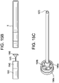
- FIGS. 15A-15C illustrates an example embodiment of a non-combustible smoking device 1500.
- FIG. 15B illustrates a semi-exploded view of the non-combustible smoking device 1500.
- FIG. 15C illustrates a plan view of a gasket 1560 and an airflow element 1570.
- FIG. 15A illustrates an example embodiment of a non-combustible smoking device 1500 including a tobacco housing 1540 containing a tobacco element 1550.
- the non-combustible smoking device 1500 is similar to the non-combustible smoking device 60 except a section 70c does not include the mouth-end insert 8 and the tobacco element 23 and the non-combustible smoking device 1500 further includes an insert 1510. Therefore, for the sake of brevity, only the differences will be described.
- the non-combustible smoking device 1500 includes a receiving area 1505 fitted to receive the insert 1510.
- the receiving area 1505 is defined by the outer tube 6 and the gasket 10.
- the tobacco insert 1510 may be a cigarette or cigar containing the gasket 1560 and the air flow element 1570.
- the tobacco insert 1510 may be a filtered cigarette, a non-filtered cigarette, a cigarillo, a filter tipped cigar filter, a tipped cigar or an untipped cigar/cigarillo, for example.
- example embodiments are not limited thereto.
- the tobacco insert 1510 is a detachable insert.
- the tobacco insert 1510 includes a filter 1520, the tobacco housing 1540, the gasket 1560 and the air flow element 1570. While only the gasket 1560 is illustrated in FIG. 15A , it should be understood that additional gaskets may be present. For example, for a longer air flow element, a second gasket may be used between the tobacco housing 1540 and the filter 1520 in order to stabilize the tubing. In an example, the tobacco housing 1540 may be 15-25 millimetres long in the longitudinal direction and 8 millimetres wide.
- the gasket 1560 is between the gasket 10 and the tobacco element 1550.
- the gasket 1560 prevents the tobacco element 1550 from spilling into the channel 9 and holds the air flow element 1570.
- the gasket 1560 includes a cylindrical receiving portion 1560a and holes 1560b.
- the holes 1560b connect the channel 9 to the tobacco element 1550, therefore allowing generated vapor to flow from the channel 9 into the tobacco element 1550 and then into the filter 1520.
- the air flow element 1570 is attached to the gasket 1560 by inserting the air flow element 1570 into the cylindrical receiving portion 1560a.
- the air flow element 1570 and the cylindrical receiving portion 1560a may be connected using a ferrule.
- a ferrule with a specific identification is used with an air flow element 1570 that corresponds to the specific identification.
- the ferrule is then incorporated into the gasket 1560.
- the air flow element 1570 is glued to the receiving portion 1560a.
- FIG. 15C illustrates the arrangement of the gasket 1560 and the air flow element 1570 in more detail.
- the receiving portion 1560a protrudes from a base portion 1560c of the gasket 1560.
- the base portion 1560c is circular shaped.
- the holes 1560b extend through the base portion 1560c from a first exposed surface to a second exposed surface in the longitudinal direction of the receiving portion 1560a.
- the airflow element 1570 extends in the longitudinal direction of the device 1500 through the tobacco housing 1540.
- the air flow element 1570 provides an air passage from the channel 9 to the filter 1520.
- the air flow element 1570 may be a capillary tube made of at least one of PEEK and stainless steel.
- the air flow element 1570 extends in the longitudinal direction from a first end portion of the tobacco housing 1540 to an opposing second end portion of the tobacco housing 1540.
- the air flow element 1570 includes a cylindrical surface 1572 that extends from a portion of the gasket 1560 closest to the reservoir to the filter 1520.
- a channel 1574 is defined by an inner surface area of the air flow element 1570, which is an inner diameter (ID) of the air flow element 1570 extending from a portion of the gasket 1560 closest to the reservoir to the filter 1520.
- ID inner diameter
- the air flow element 1570 allows a desired amount of generated vapor (for example, 20 percent) to flow through the housing 1540 without passing through the tobacco element 1550. The remaining amount of generated vapor (for example, 80 percent) passes through the tobacco element 1550.
- the air flow element 1570 prevents the desired amount of generated vapor not exposed to the tobacco element 1550 from reacting with the tobacco element 1550.
- the desired amount of generated vapor to flow through the housing 1540 without passing through the tobacco element 1550 is 65 percent.
- the size of the air flow element 1570 (for example, inner volume) is based on the desired amount of generated vapor to flow through the channel 1574.
- the air flow element 1570 has an inner diameter of 0.5 millimetres to 3 millimetres and an outer diameter of 0.5-1.5 millimetres.
- the air flow element 1570 has an inner diameter of 2 millimetres to 2.5 millimetres.
- the air flow element 1570 has an outer diameter of 1.59 millimetres and an inner diameter of 1.02 millimetres.
- the air flow element 1570 may be 15-25 millimetres in length, but could be longer or shorter based on the length of housing 6.
- the air flow element 1570 may have a constant inner diameter or a varying inner diameter.
- the air flow element 1570 divides the tobacco element 1550 into two equal halves 1550a and 1550b.
- the air flow element 1570 may be placed in any location that allows generated vapor to flow through the housing 1540 without passing through the tobacco element 1550.
- multiple air flow elements may be used instead of one to generate a desired amount of generated vapor not exposed to the tobacco element 1550.
- the air flow element 1570 can be straight, spirally or curved towards the filter 1520.
- the air flow element 1570 may be heated. When heated, the air flow element 1570 also provides heat to the tobacco element 1550.
- the air flow element 1570 and the gasket 1560 may be made of a conductive material (for example, stainless steel).
- the gasket 1560 is connected to the heater 14 to conduct heat to the air flow element 1570.
- the gasket 1560 may be connected to the heater 14 by a wire along the housing 6 from the heater 14 to the gasket 1560.
- Tipping paper 1555 may overlap the filter 1520 and the tobacco housing 1540.
- the tipping paper 1555 may cover surface areas of the tobacco insert 1510 that extend in along the outer tube 6. Therefore, the tipping paper 1555 provides stiffness to the tobacco insert 1510, permitting easier insertion to the receiving area 1505.
- An aluminum foil may also be used to contain the tobacco element 1550, with or without additional tipping paper.
- the position of the heater 14 is not limited to the position shown in FIG. 15A .
- the heater 14 may be positioned at the end of the outer air passage 9 such that the heater 14 is closer to the tobacco element 1550, in contact with the tobacco element 1550, or both.
- the heater 14 may protrude out of the outer air passage 9.
- a negative pressure may be applied on the tobacco insert 1510.
- the negative pressure may cause an internal pressure drop inside non-combustible smoking device 1500 that may cause an inlet air flow to enter the device 1500 via air inlets 44/44'.
- the internal pressure drop may also cause an internal pressure drop within section 72 as air is drawn through air inlet 44a (via an air flow path traveling through section 72).
- the internal pressure drop formed in section 72 may be sensed by sensor 16.
- the sensor 16 may then operate to close an electrical circuit that includes the power supply 1.
- electrical leads carry an electrical current to heater 14 in order to energize the heater 14.
- the energized heater 14 in turn heats and vaporizes a portion of the pre-vapor formulation that is drawn toward the heater 14 via the wick 28.
- Pre-vapor formulation material is transferred from at least one of the pre-vapor formulation supply reservoir 22 and pre-vapor formulation storage medium 21 in proximity of the heater 14 by capillary action in the wick 28.
- the pre-vapor formulation in the central portion of the wick 28 is vaporized by the heater 14 to vaporize the pre-vapor formulation material and form generated vapor. Due to a negative pressure being applied, the generated vapor flows from the heater 14, through the tobacco element 1550 and the channel 1574 and out of the filter 1520.
- the filter 1520 may be a cellulose acetate (CA) filter.
- CA filter elements such as triacetin, can be eluted into generated vapor. Vapor phase nicotine and other volatile elements in generated vapor can be reduced by a presence of tobacco.
- FIG. 15D illustrates another example embodiment of a non-combustible smoking device including a tobacco housing for tobacco and an airflow element in the tobacco housing.
- a non-combustible smoking device 1500' is similar to the non-combustible smoking device 1500. Therefore, only the differences will be described.
- the non-combustible smoking device 1500' includes a tobacco insert 1510' including an air-flow element 1570'.
- the air-flow element 1570' extends in the longitudinal direction from the first end portion of the tobacco housing 1540 to an end 1588 of the tobacco insert 1510'.
- a channel 1574' is defined by an inner surface area of the air flow element 1570', which is an inner diameter of the air flow element 1570' extending from a portion of the gasket 1560 closest to the reservoir to the filter 1520. As shown in FIG. 15D , the channel 1574' is exposed. Therefore, the air-flow element 1570' creates an air path from the channel 9 to out of the non-combustible smoking device 1500' without the generated vapor being exposed to a filter 1520' and the tobacco element 1550.
- FIG. 15E illustrates another example embodiment of a non-combustible smoking device including a tobacco housing for tobacco and an airflow element in the tobacco housing.
- a non-combustible smoking device 1500" is the same as the non-combustible smoking device 1500 except the tobacco insert 1510" includes a second gasket 1590.
- the second gasket 1590 may be the same as the gasket 1560, but is not limited thereto.
- the gasket 1590 is in the middle of the tobacco housing 1540 (for example, 40-60 percent from either end of the tobacco housing 1540).
- the gasket 1590 provides additional stability to the air flow element 1570.
- an extra gasket is illustrated in an embodiment where the air-flow element 1570 does not extend through the filter 1520, it should be understood that a second gasket may be omitted in the tobacco insert 1510", as shown in FIG. 15D .
- FIGS. 15A-15E illustrate a gasket 1560
- the tobacco insert may not have the gasket 1560.
- the air flow element 1570 may be connected to the gasket 10.
- FIG. 16A illustrates an example embodiment of a non-combustible smoking device including a divider in a channel.
- FIG. 16A illustrates an example embodiment of a non-combustible smoking device 1600 including a tobacco element 1650 and a divider 1660.
- the non-combustible smoking device 1600 is similar to the non-combustible smoking device 60 except a section 70c does not include the mouth-end insert 8 and the tobacco element 23 and the non-combustible smoking device 1600 further includes an insert 1610. Therefore, for the sake of brevity, only the differences will be described.
- the non-combustible smoking device 1600 By removing the mouth-end insert 8, the non-combustible smoking device 1600 includes a receiving area 1605 fitted to receive a tobacco insert 1610.
- the receiving area 1605 is defined by the outer tube 6 and the gasket 10.
- the tobacco insert 1610 is a detachable insert.
- the tobacco insert 1610 may be a cigarette or a portion of a cigarette.
- the tobacco insert 1610 includes a filter 1620 and the tobacco element 1650.
- the tobacco insert 1610 does not include a filter.
- the divider 1660 is attached to an outer wall (for example, tipping paper) 1655 of the tobacco insert 1610.
- the divider 1660 may be glued to the outer wall 1655. After the divider 1660 is attached to the outer wall 1655, the tobacco1650 may be inserted into the insert 1610.
- the divider 1660 may be a stainless steel wall extending in a longitudinal direction of the device 1600 and divides a channel 1680 between the air channel 9 and the filter 1620 in the longitudinal direction into an air channel 1680a and a tobacco channel 1680b.
- the air channel 1680a and the tobacco channel 1680b are defined by the gasket 10, the housing 6, the divider 1660 and the filter 1620.
- the channel 1680 may be considered a second portion of the channel 9 since generated vapor flows from the channel 9 through the gasket 1670 into the channel 1680.
- the divider 1660 separates a portion of the tobacco insert 1610 a two compartment air channel 1680, where the tobacco channel 1680b includes the tobacco element 1650 and the air channel 1680a which does not include tobacco.
- the position of the divider 1660 allows a desired amount of generated vapor (for example, 20 percent) to flow through the channel 1680 without passing through the tobacco element 1650.
- the remaining amount of generated vapor (for example, 80 percent) passes through the tobacco element 1650.
- the divider 1650 prevents the desired amount of generated vapor not exposed to the tobacco element 1650 from reacting with the tobacco element 1650.
- the desired amount of generated vapor to flow through the channel 1680 without passing through the tobacco element 1650 is 65 percent.
- the air channel 1680a may be smaller than the tobacco channel 1680b in volume.
- the divider 1660 may positioned at a distance of 65 percent of a diameter of the housing 6 in a first radial direction of the housing 6 and a distance of 35 percent of the diameter of the housing 6 in an opposite second radial direction of the housing 6.
- the divider 1660 may be 1 millimetre thick and can be heated to avoid condensation.
- the length and width of the divider 1660 are dependent on the length and width of the channel 1680b.
- the divider 1660 has a same length (in longitudinal direction) and width of the channel 1680b, such as 15-25 millimetres long and 8 millimetres wide.
- the heated divider 1660 may heat the tobacco element 1650.
- the divider 1660 also provides heat to the tobacco element 1650.
- the divider 1660 and the gasket 10 may be made of a conductive material (for example, stainless steel).
- the gasket 10 is connected to the heater 14 to conduct heat to the divider 1660.
- the divider 1660 may be connected to the heater 14 by a wire along the housing 6 from the heater 14 to the gasket 1560.
- Tipping paper 1655 may overlap the filter 1620 and the tobacco element 1650.
- the tipping paper 1655 may cover surface areas of the tobacco insert 1610 that extend in along the outer tube 6. Therefore, the tipping paper 1655 provides stiffness to the tobacco insert 1610, permitting easier insertion to the receiving area 1605.
- An aluminum foil may also be used to contain the tobacco element 1650, with or without additional tipping paper.
- the position of the heater 14 is not limited to the position shown in FIG. 16A .
- the heater 14 may be positioned at the end of the outer air passage 9 such that the heater 14 is closer to the tobacco element 1650, in contact with the tobacco element 1650, or both.
- the heater 14 may protrude out of the outer air passage 9 in the same manner as shown in FIG. 11B .
- the heater 14 may be a set distance from the tobacco element 1650 or contacting the tobacco element 1650 such that the heater 14 heats the tobacco element 1650 to a temperature (as described above) during an application of a negative pressure.
- a negative pressure may be applied on the tobacco insert 1610.
- the negative pressure may cause an internal pressure drop inside non-combustible smoking device 1600 that may cause an inlet air flow to enter the device 1600 via air inlets 44/44'.
- the internal pressure drop may also cause an internal pressure drop within section 72 as air is drawn through air inlet 44a (via an air flow path traveling through section 72).
- the internal pressure drop formed in section 72 may be sensed by sensor 16.
- the sensor 16 may then operate to close an electrical circuit that includes the power supply 1.
- electrical leads carry an electrical current to heater 14 in order to energize the heater 14.
- the energized heater 14 in turn heats and vaporizes a portion of the pre-vapor formulation that is drawn toward the heater 14 via the wick 28.
- Pre-vapor formulation material is transferred from at least one of the pre-vapor formulation supply reservoir 22 and pre-vapor formulation storage medium 21 in proximity of the heater 14 by capillary action in the wick 28.
- the pre-vapor formulation in the central portion of the wick 28 is vaporized by the heater 14 to vaporize the pre-vapor formulation material and form generated vapor. Due to a negative pressure being applied, the generated vapor flows from the heater 14, through the tobacco element 1650 and the air channel 1680a and out of the filter 1620.
- the filter 1620 may be a cellulose acetate (CA) filter.
- CA filter elements such as triacetin, can be eluted into generated vapor. Vapor phase nicotine and other volatile elements in generated vapor can be reduced by a presence of tobacco.
- FIG. 16B illustrates an example embodiment of a non-combustible smoking device including a divider in a channel.
- a non-combustible smoking device 1600' is similar to the non-combustible smoking device 1600. Therefore, only the differences will be described.
- a gasket 1670 is located between the filter 1620 and the channels 1680a and 1680b.
- the gasket 1670 increases the stability of a tobacco insert 1610'.
- FIG. 17 illustrates a gasket according to an example embodiment.
- a gasket 1705 includes an outer circular wall 1710 and an inner circular wall 1715.
- the inner circular wall 1715 defines a cylindrical channel 1720 though the gasket 1705.
- the inner circular wall 1715 may have the same inner diameter as the receiving portion 1562. In other words, the inner circular wall 1715 is fitted to receive the air flow element 1570.
- the outer circular wall 1710 and the inner circular wall 1715 are connected together by a bottom portion 1725.
- the cylindrical channel 1720 has an inner diameter of 2 millimetres and the gasket has an outer diameter of 8 millimetres and an inner diameter of 6 millimetres.
- FIGS. 18A-18E illustrate other example embodiments of a tobacco housing. As shown, the example embodiments illustrated in FIGS. 18A-18E illustrate a tobacco housing and a portion of a non-combustible smoking device without the gasket 10. Instead, the gasket 1560 is adjacent the pre-vapor formulation supply reservoir 22. For the sake of brevity, only the differences between the example embodiments of FIGS. 18A-18E and FIGS. 15A-15E will be described.
- the gasket 1560 is adjacent the pre-vapor formulation supply reservoir 22.
- An air flow element 1570a extends through the tobacco housing 1840a.
- the tobacco housing 1840a and the air flow element 1570a are the same as the tobacco housing 1540 and the air flow element, 1570, respectively, except the tobacco housing 1840a and the air flow element 1570a are longer due to the absence of the gasket 10.
- FIG. 18B illustrates a tobacco housing according to another example embodiment. Similar to FIG. 18A , the gasket 1560 defines one end of a tobacco housing 1840b and is adjacent to the pre-vapor formulation supply reservoir 22. At an opposite end, the gasket 1705 defines another end of the tobacco housing 1840b.
- the airflow element 1570a extends from the channel 9, through the tobacco housing 1840b to a mouthpiece 1850.
- tipping paper may be used to contain the tobacco.
- FIG. 18C illustrates a tobacco housing according to another example embodiment.
- a tobacco housing 1840c is the same as the tobacco housing 1840b, shown in FIG. 18B , except the tobacco housing 1840c includes another gasket 1562 in a middle of the tobacco housing 1840c.
- the gasket 1562 is the same as the gasket 1560.
- FIG. 18D illustrates a tobacco housing according to another example embodiment.
- a tobacco housing 1840d is the same as the tobacco housing 1840c, shown in FIG. 18C , except the tobacco housing 1840d includes a gasket 1564 in place of the gasket 1705.
- the gasket 1564 is the same as the gaskets 1562 and 1560.
- FIG. 18E illustrates a tobacco housing according to another example embodiment.
- a tobacco housing 1840e is the same as the tobacco housing 1840c, shown in FIG. 18C , except the tobacco housing 1840e includes a gasket 1705a in place of the gasket 1562.
- the gasket 1705a is the same as the gasket 1705.
Landscapes
- Cigarettes, Filters, And Manufacturing Of Filters (AREA)
- Manufacture Of Tobacco Products (AREA)
- Catching Or Destruction (AREA)
- Resistance Heating (AREA)
Claims (16)
- Nichtbrennbares Rauchelement, aufweisend:einen Vordampfformulierungsvorratsbehälter (22), der derart ausgelegt ist, dass er ein Vordampfformulierungsmaterial enthält;ein Heizelement (14), das mit dem Vordampfformulierungsvorratsbehälter gekoppelt und ausgelegt ist, zumindest einen Teil des Vordampfformulierungsmaterials zu Rohdampf zu erwärmen und den Rohdampf an einem ersten Abschnitt eines Kanals (9) vorzusehen;ein Tabakgehäuse (1540) an einem zweiten Abschnitt des Kanals und so positioniert, dass es den Rohdampf aufnimmt, wobei das Tabakgehäuse Tabak (1550) beinhaltet; undzumindest ein Luftstromelement (1570, 1570') in dem Tabakgehäuse, um zumindest einen ersten Abschnitt des Rohdampfes zu einem Ende des nichtbrennbaren Rauchelements zu lenken,wobei das Luftstromelement das Tabakgehäuse in einen ersten Abschnitt und einen zweiten Abschnitt trennt, wobei der erste Abschnitt ausgelegt ist, zu verhindern, dass der erste Abschnitt des Rohdampfes dem Tabak ausgesetzt wird.
- Nichtbrennbares Rauchelement nach Anspruch 1, wobei sich das Luftstromelement von einem ersten Endabschnitt des Tabakgehäuses zu einem gegenüberliegenden zweiten Endabschnitt des Tabakgehäuses erstreckt.
- Nichtbrennbares Rauchelement nach Anspruch 1, wobei der erste Abschnitt des Rohdampfes etwa 65 Prozent des gesamten Rohdampfes beträgt.
- Nichtbrennbares Rauchelement nach einem der vorstehenden Ansprüche, wobei das Luftstromelement ein Rohr ist.
- Nichtbrennbares Rauchelement nach Anspruch 4, wobei das Rohr einen Innendurchmesser von 0,5 Millimeter bis 3 Millimeter, bevorzugt von 2 Millimeter bis 2,5 Millimeter, hat.
- Nichtbrennbares Rauchelement nach einem der vorstehenden Ansprüche, wobei das Luftstromelement das Tabakgehäuse in zwei Abschnitte unterteilt.
- Nichtbrennbares Rauchelement nach einem der vorstehenden Ansprüche, wobei das Luftstromelement zumindest eines von Polyetheretherketon (PEEK) und Metall beinhaltet.
- Nichtbrennbares Rauchelement (1600, 1600'), aufweisend:einen Vordampfformulierungsvorratsbehälter (22), der derart ausgelegt ist, dass er ein Vordampfformulierungsmaterial enthält;ein Heizelement (14), das mit dem Vordampfformulierungsvorratsbehälter gekoppelt und ausgelegt ist, zumindest einen Teil des Vordampfformulierungsmaterials zu Rohdampf zu erwärmen und den Rohdampf an einem ersten Abschnitt eines Kanals (9) vorzusehen;einen Teiler (1660), der sich in einem zweiten Abschnitt (1680) des Kanals erstreckt, wobei sich der Teiler in einer Längsrichtung erstreckt und den zweiten Abschnitt des Kanals in einen einzelnen Luftkanalteil (1680a) und einen Tabakteil (1680b) teilt, wobei der einzelne Luftkanalteil (1680a) und der Tabakteil (1680b) positioniert sind, um den Rohdampf aufzunehmen, wobei der Tabakteil (1680b) beinhaltet,einen Tabakteil (1650) mit Tabak, wobei der Tabakteil (1650) so positioniert ist, dass er einen ersten Abschnitt des Rohdampfes aufnimmt,wobei die Position des Teilers ermöglicht, dass eine gewünschte Menge an Rohdampf durch den Kanal strömt, ohne durch das Tabakteil (1650) zu strömen.
- Nichtbrennbares Rauchelement nach Anspruch 8, wobei der Teiler Metall beinhaltet und ausgelegt ist, die durch das Heizelement erzeugte Wärme zum Erwärmen des Tabaks zu leiten.
- Nichtbrennbares Rauchelement nach Anspruch 8 oder 9, wobei das einzelne Luftkanalteil volumenmäßig größer ist als das Tabakteil.
- Nichtbrennbares Rauchelement nach Anspruch 8, 9 oder 10, ferner aufweisend:
ein Gehäuse (6) mit einem Innendurchmesser, das sich in Längsrichtung erstreckt, wobei das Gehäuse den Vordampfformulierungsvorratsbehälter, das Heizelement und den Teiler aufnimmt, wobei der Teiler in einem Abstand von 65 Prozent des Durchmessers in einer ersten Richtung zum Gehäuse und einem Abstand von 35 Prozent des Durchmessers in einer zweiten Richtung zum Gehäuse positioniert ist. - Nichtbrennbare Vorrichtung zum Rauchen (1500, 1500', 1500"), aufweisend:einen Vordampfformulierungsvorratsbehälter (22), der derart ausgelegt ist, dass er ein Vordampfformulierungsmaterial enthält;ein Heizelement (14), das mit dem Vordampfformulierungsvorratsbehälter gekoppelt und ausgelegt ist, zumindest einen Teil des Vordampfformulierungsmaterials zu Rohdampf zu erwärmen und den Rohdampf an einem ersten Abschnitt eines Kanals (9) vorzusehen;eine Stromversorgung (1), die ausgelegt ist, Strom an das Heizelement bereitzustellen;ein Tabakgehäuse (1540) an einem zweiten Abschnitt des Kanals und so positioniert, dass es den Rohdampf aufnimmt, wobei das Tabakgehäuse Tabak (1550) beinhaltet; undzumindest ein Luftstromelement (1570, 1570') in dem Tabakgehäuse, um zumindest einen ersten Abschnitt des Rohdampfes zu einem Ende des nichtbrennbaren Rauchelements zu lenken,wobei das Luftstromelement das Tabakgehäuse in einen ersten Abschnitt und einen zweiten Abschnitt trennt, wobei der erste Abschnitt ausgelegt ist, zu verhindern, dass der erste Abschnitt des Rohdampfes dem Tabak ausgesetzt wird.
- Nichtbrennbare Vorrichtung zum Rauchen nach Anspruch 12, wobei sich das Luftstromelement von einem ersten Endabschnitt des Tabakgehäuses zu einem gegenüberliegenden zweiten Endabschnitt des Tabakgehäuses erstreckt.
- Nichtbrennbare Vorrichtung zum Rauchen nach Anspruch 12, wobei der erste Abschnitt des Rohdampfes etwa 65 Prozent des gesamten Rohdampfes beträgt.
- Nichtbrennbare Vorrichtung zum Rauchen nach einem der Ansprüche 12 bis 14, wobei das Luftstromelement ein Rohr ist.
- Nichtbrennbares Rauchelement nach Anspruch 16, wobei das Rohr einen Innendurchmesser von 0,5 Millimeter bis 3 Millimeter, bevorzugt von 2 Millimeter bis 2,5 Millimeter, hat.
Priority Applications (1)
| Application Number | Priority Date | Filing Date | Title |
|---|---|---|---|
| PL17778303T PL3522740T3 (pl) | 2016-10-04 | 2017-10-04 | Niepalne urządzenie do palenia i jego elementy |
Applications Claiming Priority (2)
| Application Number | Priority Date | Filing Date | Title |
|---|---|---|---|
| US15/284,897 US10842193B2 (en) | 2016-10-04 | 2016-10-04 | Non-combustible smoking device and elements thereof |
| PCT/EP2017/075254 WO2018065489A1 (en) | 2016-10-04 | 2017-10-04 | Non-combustible smoking device and elements thereof |
Publications (2)
| Publication Number | Publication Date |
|---|---|
| EP3522740A1 EP3522740A1 (de) | 2019-08-14 |
| EP3522740B1 true EP3522740B1 (de) | 2021-03-24 |
Family
ID=60009649
Family Applications (1)
| Application Number | Title | Priority Date | Filing Date |
|---|---|---|---|
| EP17778303.2A Active EP3522740B1 (de) | 2016-10-04 | 2017-10-04 | Nichtbrennbare rauchvorrichtung und elemente davon |
Country Status (12)
| Country | Link |
|---|---|
| US (2) | US10842193B2 (de) |
| EP (1) | EP3522740B1 (de) |
| JP (1) | JP7194677B2 (de) |
| KR (1) | KR102578973B1 (de) |
| CN (1) | CN109688853B (de) |
| CA (1) | CA3032910A1 (de) |
| ES (1) | ES2865349T3 (de) |
| IL (1) | IL265728A (de) |
| MX (1) | MX2019003641A (de) |
| PL (1) | PL3522740T3 (de) |
| RU (1) | RU2749517C2 (de) |
| WO (1) | WO2018065489A1 (de) |
Cited By (3)
| Publication number | Priority date | Publication date | Assignee | Title |
|---|---|---|---|---|
| US11350664B2 (en) | 2018-11-08 | 2022-06-07 | Juul Labs, Inc. | Vaporizer device with more than one heating element |
| US11464082B2 (en) | 2018-07-31 | 2022-10-04 | Juul Labs, Inc. | Cartridge-based heat not burn vaporizer |
| US11730199B2 (en) | 2018-06-07 | 2023-08-22 | Juul Labs, Inc. | Cartridges for vaporizer devices |
Families Citing this family (11)
| Publication number | Priority date | Publication date | Assignee | Title |
|---|---|---|---|---|
| WO2016179376A1 (en) * | 2015-05-06 | 2016-11-10 | Altria Client Services Llc | Non-combustible smoking device and elements thereof |
| US10455863B2 (en) * | 2016-03-03 | 2019-10-29 | Altria Client Services Llc | Cartridge for electronic vaping device |
| US10433585B2 (en) * | 2016-12-28 | 2019-10-08 | Altria Client Services Llc | Non-combustible smoking systems, devices and elements thereof |
| BR112020004583A2 (pt) * | 2017-10-13 | 2020-09-08 | Philip Morris Products S.A. | artigo gerador de aerossol com uma cavidade com material de alteração de aerossol particulado |
| CN208434718U (zh) * | 2018-06-22 | 2019-01-29 | 湖南中烟工业有限责任公司 | 一种电子烟雾化器及该电子烟 |
| US11491299B2 (en) | 2019-04-20 | 2022-11-08 | Flat Planet Limited | Dual convection and conduction oven for flower stick |
| EP3738453B1 (de) * | 2019-05-13 | 2022-03-30 | Tuanfang Liu | Elektronische zigarette |
| WO2021105184A1 (en) * | 2019-11-29 | 2021-06-03 | Jt International Sa | Electronic cigarette |
| GB202011517D0 (en) * | 2020-07-24 | 2020-09-09 | Nicoventures Trading Ltd | Aerosol provision system |
| EP4188129A1 (de) * | 2020-07-29 | 2023-06-07 | Acetate International LLC | Katalysatoreinführungsverfahren zur beschleunigten deacetylierung von celluloseestern |
| CA3190603A1 (en) * | 2020-07-31 | 2022-02-03 | Flat Planet Limited | Dual convection and conduction oven for flower stick |
Family Cites Families (106)
| Publication number | Priority date | Publication date | Assignee | Title |
|---|---|---|---|---|
| US4393884A (en) | 1981-09-25 | 1983-07-19 | Jacobs Allen W | Demand inhaler for oral administration of tobacco, tobacco-like, or other substances |
| US5042509A (en) | 1984-09-14 | 1991-08-27 | R. J. Reynolds Tobacco Company | Method for making aerosol generating cartridge |
| US5067499A (en) | 1984-09-14 | 1991-11-26 | R. J. Reynolds Tobacco Company | Smoking article |
| US4793365A (en) | 1984-09-14 | 1988-12-27 | R. J. Reynolds Tobacco Company | Smoking article |
| US4854331A (en) | 1984-09-14 | 1989-08-08 | R. J. Reynolds Tobacco Company | Smoking article |
| US5020548A (en) | 1985-08-26 | 1991-06-04 | R. J. Reynolds Tobacco Company | Smoking article with improved fuel element |
| US4917128A (en) | 1985-10-28 | 1990-04-17 | R. J. Reynolds Tobacco Co. | Cigarette |
| US5060666A (en) | 1985-10-28 | 1991-10-29 | R. J. Reynolds Tobacco Company | Smoking article with tobacco jacket |
| US5033483A (en) | 1985-10-28 | 1991-07-23 | R. J. Reynolds Tobacco Company | Smoking article with tobacco jacket |
| US4756318A (en) | 1985-10-28 | 1988-07-12 | R. J. Reynolds Tobacco Company | Smoking article with tobacco jacket |
| US4708151A (en) | 1986-03-14 | 1987-11-24 | R. J. Reynolds Tobacco Company | Pipe with replaceable cartridge |
| IL83826A (en) | 1987-09-08 | 1991-03-10 | Inventor S Funding Corp Ltd | Plastic mouthpiece for simulated smoking |
| US4947874A (en) | 1988-09-08 | 1990-08-14 | R. J. Reynolds Tobacco Company | Smoking articles utilizing electrical energy |
| DE3908160A1 (de) | 1989-03-13 | 1990-09-27 | Bat Cigarettenfab Gmbh | Rauchbarer artikel |
| US4961438A (en) | 1989-04-03 | 1990-10-09 | Brown & Williamson Tobacco Corporation | Smoking device |
| US5060671A (en) | 1989-12-01 | 1991-10-29 | Philip Morris Incorporated | Flavor generating article |
| GB9102658D0 (en) | 1991-02-07 | 1991-03-27 | British American Tobacco Co | Improvements relating to smoking articles |
| US5065776A (en) | 1990-08-29 | 1991-11-19 | R. J. Reynolds Tobacco Company | Cigarette with tobacco/glass fuel wrapper |
| US5203355A (en) | 1991-02-14 | 1993-04-20 | R. J. Reynolds Tobacco Company | Cigarette with cellulosic substrate |
| US5240016A (en) | 1991-04-19 | 1993-08-31 | Philip Morris Incorporated | Thermally releasable gel-based flavor source for smoking articles |
| US5159942A (en) | 1991-06-04 | 1992-11-03 | R. J. Reynolds Tobacco Company | Process for providing smokable material for a cigarette |
| US5235992A (en) | 1991-06-28 | 1993-08-17 | R. J. Reynolds Tobacco Company | Processes for producing flavor substances from tobacco and smoking articles made therewith |
| US5293883A (en) | 1992-05-04 | 1994-03-15 | Edwards Patrica T | Non-combustible anti-smoking device with nicotine impregnated mouthpiece |
| US5595706A (en) | 1994-12-29 | 1997-01-21 | Philip Morris Incorporated | Aluminum containing iron-base alloys useful as electrical resistance heating elements |
| US6532965B1 (en) | 2001-10-24 | 2003-03-18 | Brown & Williamson Tobacco Corporation | Smoking article using steam as an aerosol-generating source |
| US20060272659A1 (en) * | 2005-06-06 | 2006-12-07 | Gerd Kobal | Modular smoking article and method of use |
| US20070215167A1 (en) | 2006-03-16 | 2007-09-20 | Evon Llewellyn Crooks | Smoking article |
| WO2007078273A1 (en) * | 2005-12-22 | 2007-07-12 | Augite Incorporation | No-tar electronic smoking utensils |
| US20070267033A1 (en) * | 2006-02-09 | 2007-11-22 | Philip Morris Usa Inc. | Gamma cyclodextrin flavoring-release additives |
| US7726320B2 (en) | 2006-10-18 | 2010-06-01 | R. J. Reynolds Tobacco Company | Tobacco-containing smoking article |
| US7845359B2 (en) | 2007-03-22 | 2010-12-07 | Pierre Denain | Artificial smoke cigarette |
| CN201127292Y (zh) | 2007-12-21 | 2008-10-08 | 中国烟草总公司郑州烟草研究院 | 一种无烟型电子烟 |
| AT507187B1 (de) | 2008-10-23 | 2010-03-15 | Helmut Dr Buchberger | Inhalator |
| TW201023769A (en) | 2008-10-23 | 2010-07-01 | Japan Tobacco Inc | Non-burning type flavor inhalation article |
| GB0918129D0 (en) | 2009-10-16 | 2009-12-02 | British American Tobacco Co | Control of puff profile |
| CN102905565B (zh) | 2010-05-21 | 2016-08-24 | 环球蒸汽商标公司 | 制备用于电吸烟设备的烟草提取物的方法 |
| CN201830900U (zh) | 2010-06-09 | 2011-05-18 | 李永海 | 电子香烟的烟液雾化装置 |
| US20120199146A1 (en) | 2011-02-09 | 2012-08-09 | Bill Marangos | Electronic cigarette |
| US9078473B2 (en) | 2011-08-09 | 2015-07-14 | R.J. Reynolds Tobacco Company | Smoking articles and use thereof for yielding inhalation materials |
| KR102309513B1 (ko) * | 2011-09-06 | 2021-10-05 | 니코벤처스 트레이딩 리미티드 | 가열식 흡연가능 재료 |
| EP2574247B1 (de) | 2011-09-28 | 2019-08-28 | Philip Morris Products S.A. | Permeable elektrische Heizwiderstandsfolie zum Verdampfen von Flüssigkeiten aus Einwegmundstücken mit Verdampfermembranen |
| US9351522B2 (en) | 2011-09-29 | 2016-05-31 | Robert Safari | Cartomizer e-cigarette |
| TW201340893A (zh) | 2011-12-20 | 2013-10-16 | British American Tobacco Co | 吸煙物件及其他氣流輸送物件(一) |
| AU2011384327B2 (en) | 2011-12-23 | 2016-06-02 | Kimree Hi-Tech Inc. | Electronic cigarette suction nozzle |
| JP5887667B2 (ja) | 2011-12-23 | 2016-03-16 | 恵州市吉瑞科技有限公司深▲せん▼分公司 | 電子タバコ吸引ノズル |
| WO2013097158A1 (zh) * | 2011-12-29 | 2013-07-04 | Liu Qiuming | 固态烟油电子烟 |
| AR089602A1 (es) | 2011-12-30 | 2014-09-03 | Philip Morris Products Sa | Articulo generador de aerosoles para usar con un dispositivo generador de aerosoles |
| US9078474B2 (en) | 2012-01-30 | 2015-07-14 | Spencer Thompson | Cartomizer for electronic cigarettes |
| US9282772B2 (en) * | 2012-01-31 | 2016-03-15 | Altria Client Services Llc | Electronic vaping device |
| US20130255675A1 (en) | 2012-04-01 | 2013-10-03 | Huizhou Kimree Technology Co., Ltd. | Electronic Cigarette and Mouthpiece Part Thereof |
| CN104023571B (zh) | 2012-06-05 | 2017-02-08 | 惠州市吉瑞科技有限公司 | 电子烟及其吸杆 |
| US10004259B2 (en) | 2012-06-28 | 2018-06-26 | Rai Strategic Holdings, Inc. | Reservoir and heater system for controllable delivery of multiple aerosolizable materials in an electronic smoking article |
| CN102813278B (zh) | 2012-08-09 | 2017-03-15 | 深圳瀚星翔科技有限公司 | 一种混合型电子香烟烟液 |
| US8881737B2 (en) | 2012-09-04 | 2014-11-11 | R.J. Reynolds Tobacco Company | Electronic smoking article comprising one or more microheaters |
| US10117460B2 (en) | 2012-10-08 | 2018-11-06 | Rai Strategic Holdings, Inc. | Electronic smoking article and associated method |
| US9854841B2 (en) | 2012-10-08 | 2018-01-02 | Rai Strategic Holdings, Inc. | Electronic smoking article and associated method |
| US10154691B2 (en) | 2012-11-26 | 2018-12-18 | Nu Mark Innovations Ltd. | Bonding for an electronic cigarette cartridge |
| US20140166028A1 (en) | 2012-12-14 | 2014-06-19 | Richard C. Fuisz | Enhanced Delivery of Nicotine, THC, Tobacco, Cannabidiol or Base Alkaloid from an Electronic Cigarette or Other Vapor or Smoke Producing Device Through Use of an Absorption Conditioning Unit |
| MA20150370A1 (fr) | 2012-12-17 | 2015-10-30 | Sis Resources Ltd | Amélioration du goût d'une cigarette électronique |
| US20140182612A1 (en) * | 2012-12-28 | 2014-07-03 | Shenzhen Smoore Technology Limited | Electronic atomizing inhalation device |
| GB2513061B (en) | 2013-01-24 | 2016-10-19 | Fontem Holdings 4 Bv | Method, composition and apparatus for functionalization of aerosols from non combustible smoking articles |
| GB2511305A (en) | 2013-02-27 | 2014-09-03 | British American Tobacco Co | A smoking device and a component for a smoking device |
| GB2511303A (en) | 2013-02-27 | 2014-09-03 | British American Tobacco Co | Smoking apparatus |
| US10031183B2 (en) | 2013-03-07 | 2018-07-24 | Rai Strategic Holdings, Inc. | Spent cartridge detection method and system for an electronic smoking article |
| US20140261486A1 (en) | 2013-03-12 | 2014-09-18 | R.J. Reynolds Tobacco Company | Electronic smoking article having a vapor-enhancing apparatus and associated method |
| US9723876B2 (en) | 2013-03-15 | 2017-08-08 | Altria Client Services Llc | Electronic smoking article |
| US9877508B2 (en) | 2013-03-15 | 2018-01-30 | Altria Client Services Llc | Electronic cigarette |
| WO2014153778A1 (zh) * | 2013-03-29 | 2014-10-02 | 吉瑞高新科技股份有限公司 | 电子烟 |
| CN103393222B (zh) * | 2013-08-16 | 2015-09-16 | 湖北中烟工业有限责任公司 | 具有烟草风味的烟碱烟雾常温卷烟 |
| GB2513627B (en) | 2013-05-02 | 2018-02-07 | Jt Int Sa | Vaporisable material plug |
| US20140355969A1 (en) | 2013-05-28 | 2014-12-04 | Sis Resources, Ltd. | One-way valve for atomizer section in electronic cigarettes |
| WO2014201432A1 (en) * | 2013-06-14 | 2014-12-18 | Ploom, Inc. | Multiple heating elements with separate vaporizable materials in an electric vaporization device |
| ITMO20130192A1 (it) | 2013-06-28 | 2014-12-29 | Damco S R L | Kit per sigarette elettroniche |
| US10390562B2 (en) | 2013-07-23 | 2019-08-27 | Altria Client Services Llc | Electronic smoking article |
| US9877511B2 (en) * | 2013-07-24 | 2018-01-30 | Altria Client Services Llc | Electronic smoking article |
| US9955727B2 (en) | 2013-07-24 | 2018-05-01 | Nu Mark Innovations Ltd. | Solid core electronic cigarette |
| EP3024343A2 (de) | 2013-07-24 | 2016-06-01 | Altria Client Services LLC | Elektronischer rauchartikel mit alternativen luftstromwegen |
| US10278422B2 (en) | 2013-08-26 | 2019-05-07 | Altria Client Services Llc | Electronic cigarette with reduced energy consumption and environmental impact |
| EP3042577B1 (de) | 2013-09-30 | 2020-02-26 | Japan Tobacco Inc. | Verbrennungsfreier aromaaspirator und kapseleinheit |
| US10292424B2 (en) | 2013-10-31 | 2019-05-21 | Rai Strategic Holdings, Inc. | Aerosol delivery device including a pressure-based aerosol delivery mechanism |
| CN103519351B (zh) * | 2013-10-31 | 2017-02-15 | 红塔烟草(集团)有限责任公司 | 一种电加热卷烟 |
| US20150128968A1 (en) | 2013-11-11 | 2015-05-14 | R.J. Reynolds Tobacco Company | Mouthpiece for smoking article |
| US20150136158A1 (en) | 2013-11-15 | 2015-05-21 | Jj 206, Llc | Systems and methods for a vaporization device and product usage control and documentation |
| EP3068244A4 (de) | 2013-11-15 | 2017-07-05 | VMR Products, LLC | Verdampfer mit abdeckhülse |
| US20150164147A1 (en) | 2013-12-16 | 2015-06-18 | VMR Products, LLC | Cartridge for a vaporizor |
| CN203618787U (zh) | 2013-12-30 | 2014-06-04 | 林光榕 | 一种电子烟 |
| DE202014001718U1 (de) * | 2014-02-27 | 2015-05-28 | Xeo Holding GmbH | Rauchvorrichtung |
| CN103815547B (zh) * | 2014-03-16 | 2017-01-04 | 云南烟草科学研究院 | 一种发热体加热卷烟 |
| US9010335B1 (en) | 2014-05-13 | 2015-04-21 | Njoy, Inc. | Mechanisms for vaporizing devices |
| US20160073695A1 (en) * | 2014-05-20 | 2016-03-17 | R. J. Reynolds Tobacco Company | Electrically-powered aerosol delivery system |
| US20150335070A1 (en) | 2014-05-20 | 2015-11-26 | R.J. Reynolds Tobacco Company | Electrically-powered aerosol delivery system |
| CN204146321U (zh) | 2014-06-11 | 2015-02-11 | 湖南中烟工业有限责任公司 | 雾化器及具有该雾化器的电子烟 |
| GB201500582D0 (en) | 2015-01-14 | 2015-02-25 | British American Tobacco Co | Apparatus for heating or cooling a material contained therein |
| WO2016004576A1 (zh) * | 2014-07-08 | 2016-01-14 | 深圳市康尔科技有限公司 | 顶部注液底部换发热组件的电子烟 |
| CN104188107B (zh) * | 2014-07-30 | 2019-01-08 | 深圳市合元科技有限公司 | 可控制烟草加热量的烘焙型吸烟装置 |
| GB2529201A (en) | 2014-08-13 | 2016-02-17 | Batmark Ltd | Device and method |
| GB201418817D0 (en) | 2014-10-22 | 2014-12-03 | British American Tobacco Co | Apparatus and method for generating an inhalable medium, and a cartridge for use therewith |
| EA201790930A1 (ru) * | 2014-10-29 | 2017-08-31 | Олтриа Клайент Сервисиз Ллк | Картридж электронного вейпингового устройства |
| US11013264B2 (en) | 2014-11-19 | 2021-05-25 | Fontem Holdings 4 B.V. | Method, composition and apparatus for functionalization of aerosols from non combustible smoking articles |
| CN104397878B (zh) | 2014-11-21 | 2017-10-27 | 黄金珍 | 加热非燃烧型电子烟雾化器和电子烟 |
| CN107205482B (zh) | 2015-01-26 | 2020-02-21 | 日本烟草产业株式会社 | 非燃烧型香味吸取器、香味源单元以及非燃烧型香味吸取器用部件的制造方法 |
| GB201503411D0 (en) * | 2015-02-27 | 2015-04-15 | British American Tobacco Co | Apparatus and method for generating an inhalable medium, and a cartridge for use therewith |
| US10426199B2 (en) | 2015-02-27 | 2019-10-01 | British American Tobacco (Investments) Limited | Cartridge, components and methods for generating an inhalable medium |
| CN205072067U (zh) * | 2015-07-27 | 2016-03-09 | 湖北中烟工业有限责任公司 | 一种电加热吸烟装置 |
| CN105595431B (zh) * | 2015-12-31 | 2019-05-21 | 山东中烟工业有限责任公司 | 一种子母锅式加热非燃烧烟草装置 |
| WO2018037562A1 (ja) * | 2016-08-26 | 2018-03-01 | 日本たばこ産業株式会社 | 非燃焼型香味吸引器 |
-
2016
- 2016-10-04 US US15/284,897 patent/US10842193B2/en active Active
-
2017
- 2017-10-04 RU RU2019111710A patent/RU2749517C2/ru active
- 2017-10-04 MX MX2019003641A patent/MX2019003641A/es unknown
- 2017-10-04 JP JP2019518276A patent/JP7194677B2/ja active Active
- 2017-10-04 CA CA3032910A patent/CA3032910A1/en not_active Abandoned
- 2017-10-04 PL PL17778303T patent/PL3522740T3/pl unknown
- 2017-10-04 ES ES17778303T patent/ES2865349T3/es active Active
- 2017-10-04 EP EP17778303.2A patent/EP3522740B1/de active Active
- 2017-10-04 KR KR1020197006881A patent/KR102578973B1/ko active IP Right Grant
- 2017-10-04 WO PCT/EP2017/075254 patent/WO2018065489A1/en active Application Filing
- 2017-10-04 CN CN201780055807.7A patent/CN109688853B/zh active Active
-
2019
- 2019-03-31 IL IL265728A patent/IL265728A/en unknown
-
2020
- 2020-10-19 US US17/074,067 patent/US20210030061A1/en active Pending
Non-Patent Citations (1)
| Title |
|---|
| None * |
Cited By (3)
| Publication number | Priority date | Publication date | Assignee | Title |
|---|---|---|---|---|
| US11730199B2 (en) | 2018-06-07 | 2023-08-22 | Juul Labs, Inc. | Cartridges for vaporizer devices |
| US11464082B2 (en) | 2018-07-31 | 2022-10-04 | Juul Labs, Inc. | Cartridge-based heat not burn vaporizer |
| US11350664B2 (en) | 2018-11-08 | 2022-06-07 | Juul Labs, Inc. | Vaporizer device with more than one heating element |
Also Published As
| Publication number | Publication date |
|---|---|
| RU2019111710A3 (de) | 2020-11-26 |
| US20210030061A1 (en) | 2021-02-04 |
| EP3522740A1 (de) | 2019-08-14 |
| CN109688853B (zh) | 2021-10-29 |
| IL265728A (en) | 2019-05-30 |
| MX2019003641A (es) | 2019-08-12 |
| CA3032910A1 (en) | 2018-04-12 |
| CN109688853A (zh) | 2019-04-26 |
| RU2749517C2 (ru) | 2021-06-11 |
| JP2019531079A (ja) | 2019-10-31 |
| KR102578973B1 (ko) | 2023-09-15 |
| PL3522740T3 (pl) | 2021-08-23 |
| RU2019111710A (ru) | 2020-11-06 |
| WO2018065489A1 (en) | 2018-04-12 |
| ES2865349T3 (es) | 2021-10-15 |
| US20180092400A1 (en) | 2018-04-05 |
| JP7194677B2 (ja) | 2022-12-22 |
| KR20190055800A (ko) | 2019-05-23 |
| US10842193B2 (en) | 2020-11-24 |
Similar Documents
| Publication | Publication Date | Title |
|---|---|---|
| US11877595B2 (en) | Non-combustible smoking systems, devices and elements thereof | |
| EP3522740B1 (de) | Nichtbrennbare rauchvorrichtung und elemente davon | |
| US20210361890A1 (en) | Non-combustible smoking device and components thereof | |
| EP3383461B1 (de) | Nichtbrennbare rauchvorrichtung und elemente davon | |
| EP3383460B1 (de) | Nichtbrennbare rauchvorrichtung und elemente davon |
Legal Events
| Date | Code | Title | Description |
|---|---|---|---|
| STAA | Information on the status of an ep patent application or granted ep patent |
Free format text: STATUS: UNKNOWN |
|
| STAA | Information on the status of an ep patent application or granted ep patent |
Free format text: STATUS: THE INTERNATIONAL PUBLICATION HAS BEEN MADE |
|
| PUAI | Public reference made under article 153(3) epc to a published international application that has entered the european phase |
Free format text: ORIGINAL CODE: 0009012 |
|
| STAA | Information on the status of an ep patent application or granted ep patent |
Free format text: STATUS: REQUEST FOR EXAMINATION WAS MADE |
|
| 17P | Request for examination filed |
Effective date: 20190306 |
|
| AK | Designated contracting states |
Kind code of ref document: A1 Designated state(s): AL AT BE BG CH CY CZ DE DK EE ES FI FR GB GR HR HU IE IS IT LI LT LU LV MC MK MT NL NO PL PT RO RS SE SI SK SM TR |
|
| AX | Request for extension of the european patent |
Extension state: BA ME |
|
| DAV | Request for validation of the european patent (deleted) | ||
| DAX | Request for extension of the european patent (deleted) | ||
| REG | Reference to a national code |
Ref country code: DE Ref legal event code: R079 Ref document number: 602017035302 Country of ref document: DE Free format text: PREVIOUS MAIN CLASS: A24F0047000000 Ipc: A24F0040300000 |
|
| GRAP | Despatch of communication of intention to grant a patent |
Free format text: ORIGINAL CODE: EPIDOSNIGR1 |
|
| STAA | Information on the status of an ep patent application or granted ep patent |
Free format text: STATUS: GRANT OF PATENT IS INTENDED |
|
| RIC1 | Information provided on ipc code assigned before grant |
Ipc: A24F 40/30 20200101AFI20201007BHEP |
|
| INTG | Intention to grant announced |
Effective date: 20201026 |
|
| GRAS | Grant fee paid |
Free format text: ORIGINAL CODE: EPIDOSNIGR3 |
|
| GRAA | (expected) grant |
Free format text: ORIGINAL CODE: 0009210 |
|
| STAA | Information on the status of an ep patent application or granted ep patent |
Free format text: STATUS: THE PATENT HAS BEEN GRANTED |
|
| AK | Designated contracting states |
Kind code of ref document: B1 Designated state(s): AL AT BE BG CH CY CZ DE DK EE ES FI FR GB GR HR HU IE IS IT LI LT LU LV MC MK MT NL NO PL PT RO RS SE SI SK SM TR |
|
| REG | Reference to a national code |
Ref country code: GB Ref legal event code: FG4D |
|
| REG | Reference to a national code |
Ref country code: RO Ref legal event code: EPE |
|
| REG | Reference to a national code |
Ref country code: CH Ref legal event code: EP |
|
| REG | Reference to a national code |
Ref country code: DE Ref legal event code: R096 Ref document number: 602017035302 Country of ref document: DE |
|
| REG | Reference to a national code |
Ref country code: IE Ref legal event code: FG4D |
|
| REG | Reference to a national code |
Ref country code: CH Ref legal event code: NV Representative=s name: MURGITROYD AND COMPANY, CH Ref country code: AT Ref legal event code: REF Ref document number: 1373566 Country of ref document: AT Kind code of ref document: T Effective date: 20210415 |
|
| REG | Reference to a national code |
Ref country code: NL Ref legal event code: FP |
|
| REG | Reference to a national code |
Ref country code: LT Ref legal event code: MG9D |
|
| PG25 | Lapsed in a contracting state [announced via postgrant information from national office to epo] |
Ref country code: BG Free format text: LAPSE BECAUSE OF FAILURE TO SUBMIT A TRANSLATION OF THE DESCRIPTION OR TO PAY THE FEE WITHIN THE PRESCRIBED TIME-LIMIT Effective date: 20210624 Ref country code: NO Free format text: LAPSE BECAUSE OF FAILURE TO SUBMIT A TRANSLATION OF THE DESCRIPTION OR TO PAY THE FEE WITHIN THE PRESCRIBED TIME-LIMIT Effective date: 20210624 Ref country code: HR Free format text: LAPSE BECAUSE OF FAILURE TO SUBMIT A TRANSLATION OF THE DESCRIPTION OR TO PAY THE FEE WITHIN THE PRESCRIBED TIME-LIMIT Effective date: 20210324 Ref country code: GR Free format text: LAPSE BECAUSE OF FAILURE TO SUBMIT A TRANSLATION OF THE DESCRIPTION OR TO PAY THE FEE WITHIN THE PRESCRIBED TIME-LIMIT Effective date: 20210625 Ref country code: FI Free format text: LAPSE BECAUSE OF FAILURE TO SUBMIT A TRANSLATION OF THE DESCRIPTION OR TO PAY THE FEE WITHIN THE PRESCRIBED TIME-LIMIT Effective date: 20210324 |
|
| PG25 | Lapsed in a contracting state [announced via postgrant information from national office to epo] |
Ref country code: RS Free format text: LAPSE BECAUSE OF FAILURE TO SUBMIT A TRANSLATION OF THE DESCRIPTION OR TO PAY THE FEE WITHIN THE PRESCRIBED TIME-LIMIT Effective date: 20210324 Ref country code: LV Free format text: LAPSE BECAUSE OF FAILURE TO SUBMIT A TRANSLATION OF THE DESCRIPTION OR TO PAY THE FEE WITHIN THE PRESCRIBED TIME-LIMIT Effective date: 20210324 Ref country code: SE Free format text: LAPSE BECAUSE OF FAILURE TO SUBMIT A TRANSLATION OF THE DESCRIPTION OR TO PAY THE FEE WITHIN THE PRESCRIBED TIME-LIMIT Effective date: 20210324 |
|
| REG | Reference to a national code |
Ref country code: AT Ref legal event code: MK05 Ref document number: 1373566 Country of ref document: AT Kind code of ref document: T Effective date: 20210324 |
|
| REG | Reference to a national code |
Ref country code: ES Ref legal event code: FG2A Ref document number: 2865349 Country of ref document: ES Kind code of ref document: T3 Effective date: 20211015 |
|
| PG25 | Lapsed in a contracting state [announced via postgrant information from national office to epo] |
Ref country code: EE Free format text: LAPSE BECAUSE OF FAILURE TO SUBMIT A TRANSLATION OF THE DESCRIPTION OR TO PAY THE FEE WITHIN THE PRESCRIBED TIME-LIMIT Effective date: 20210324 Ref country code: CZ Free format text: LAPSE BECAUSE OF FAILURE TO SUBMIT A TRANSLATION OF THE DESCRIPTION OR TO PAY THE FEE WITHIN THE PRESCRIBED TIME-LIMIT Effective date: 20210324 Ref country code: LT Free format text: LAPSE BECAUSE OF FAILURE TO SUBMIT A TRANSLATION OF THE DESCRIPTION OR TO PAY THE FEE WITHIN THE PRESCRIBED TIME-LIMIT Effective date: 20210324 Ref country code: SM Free format text: LAPSE BECAUSE OF FAILURE TO SUBMIT A TRANSLATION OF THE DESCRIPTION OR TO PAY THE FEE WITHIN THE PRESCRIBED TIME-LIMIT Effective date: 20210324 Ref country code: AT Free format text: LAPSE BECAUSE OF FAILURE TO SUBMIT A TRANSLATION OF THE DESCRIPTION OR TO PAY THE FEE WITHIN THE PRESCRIBED TIME-LIMIT Effective date: 20210324 |
|
| PG25 | Lapsed in a contracting state [announced via postgrant information from national office to epo] |
Ref country code: IS Free format text: LAPSE BECAUSE OF FAILURE TO SUBMIT A TRANSLATION OF THE DESCRIPTION OR TO PAY THE FEE WITHIN THE PRESCRIBED TIME-LIMIT Effective date: 20210724 Ref country code: PT Free format text: LAPSE BECAUSE OF FAILURE TO SUBMIT A TRANSLATION OF THE DESCRIPTION OR TO PAY THE FEE WITHIN THE PRESCRIBED TIME-LIMIT Effective date: 20210726 Ref country code: SK Free format text: LAPSE BECAUSE OF FAILURE TO SUBMIT A TRANSLATION OF THE DESCRIPTION OR TO PAY THE FEE WITHIN THE PRESCRIBED TIME-LIMIT Effective date: 20210324 |
|
| REG | Reference to a national code |
Ref country code: DE Ref legal event code: R097 Ref document number: 602017035302 Country of ref document: DE |
|
| PG25 | Lapsed in a contracting state [announced via postgrant information from national office to epo] |
Ref country code: DK Free format text: LAPSE BECAUSE OF FAILURE TO SUBMIT A TRANSLATION OF THE DESCRIPTION OR TO PAY THE FEE WITHIN THE PRESCRIBED TIME-LIMIT Effective date: 20210324 Ref country code: AL Free format text: LAPSE BECAUSE OF FAILURE TO SUBMIT A TRANSLATION OF THE DESCRIPTION OR TO PAY THE FEE WITHIN THE PRESCRIBED TIME-LIMIT Effective date: 20210324 |
|
| PLBE | No opposition filed within time limit |
Free format text: ORIGINAL CODE: 0009261 |
|
| STAA | Information on the status of an ep patent application or granted ep patent |
Free format text: STATUS: NO OPPOSITION FILED WITHIN TIME LIMIT |
|
| PG25 | Lapsed in a contracting state [announced via postgrant information from national office to epo] |
Ref country code: SI Free format text: LAPSE BECAUSE OF FAILURE TO SUBMIT A TRANSLATION OF THE DESCRIPTION OR TO PAY THE FEE WITHIN THE PRESCRIBED TIME-LIMIT Effective date: 20210324 |
|
| 26N | No opposition filed |
Effective date: 20220104 |
|
| PG25 | Lapsed in a contracting state [announced via postgrant information from national office to epo] |
Ref country code: IS Free format text: LAPSE BECAUSE OF FAILURE TO SUBMIT A TRANSLATION OF THE DESCRIPTION OR TO PAY THE FEE WITHIN THE PRESCRIBED TIME-LIMIT Effective date: 20210724 |
|
| REG | Reference to a national code |
Ref country code: BE Ref legal event code: MM Effective date: 20211031 |
|
| PG25 | Lapsed in a contracting state [announced via postgrant information from national office to epo] |
Ref country code: MC Free format text: LAPSE BECAUSE OF FAILURE TO SUBMIT A TRANSLATION OF THE DESCRIPTION OR TO PAY THE FEE WITHIN THE PRESCRIBED TIME-LIMIT Effective date: 20210324 |
|
| PG25 | Lapsed in a contracting state [announced via postgrant information from national office to epo] |
Ref country code: LU Free format text: LAPSE BECAUSE OF NON-PAYMENT OF DUE FEES Effective date: 20211004 Ref country code: BE Free format text: LAPSE BECAUSE OF NON-PAYMENT OF DUE FEES Effective date: 20211031 |
|
| PG25 | Lapsed in a contracting state [announced via postgrant information from national office to epo] |
Ref country code: IE Free format text: LAPSE BECAUSE OF NON-PAYMENT OF DUE FEES Effective date: 20211004 |
|
| PG25 | Lapsed in a contracting state [announced via postgrant information from national office to epo] |
Ref country code: CY Free format text: LAPSE BECAUSE OF FAILURE TO SUBMIT A TRANSLATION OF THE DESCRIPTION OR TO PAY THE FEE WITHIN THE PRESCRIBED TIME-LIMIT Effective date: 20210324 |
|
| P01 | Opt-out of the competence of the unified patent court (upc) registered |
Effective date: 20230529 |
|
| PG25 | Lapsed in a contracting state [announced via postgrant information from national office to epo] |
Ref country code: HU Free format text: LAPSE BECAUSE OF FAILURE TO SUBMIT A TRANSLATION OF THE DESCRIPTION OR TO PAY THE FEE WITHIN THE PRESCRIBED TIME-LIMIT; INVALID AB INITIO Effective date: 20171004 |
|
| PGFP | Annual fee paid to national office [announced via postgrant information from national office to epo] |
Ref country code: RO Payment date: 20230926 Year of fee payment: 7 |
|
| PGFP | Annual fee paid to national office [announced via postgrant information from national office to epo] |
Ref country code: NL Payment date: 20231019 Year of fee payment: 7 |
|
| PGFP | Annual fee paid to national office [announced via postgrant information from national office to epo] |
Ref country code: GB Payment date: 20231020 Year of fee payment: 7 |
|
| PGFP | Annual fee paid to national office [announced via postgrant information from national office to epo] |
Ref country code: ES Payment date: 20231227 Year of fee payment: 7 |
|
| PGFP | Annual fee paid to national office [announced via postgrant information from national office to epo] |
Ref country code: IT Payment date: 20231023 Year of fee payment: 7 Ref country code: FR Payment date: 20231026 Year of fee payment: 7 Ref country code: DE Payment date: 20231020 Year of fee payment: 7 Ref country code: CH Payment date: 20231102 Year of fee payment: 7 |
|
| PGFP | Annual fee paid to national office [announced via postgrant information from national office to epo] |
Ref country code: PL Payment date: 20231002 Year of fee payment: 7 |
|
| PG25 | Lapsed in a contracting state [announced via postgrant information from national office to epo] |
Ref country code: MK Free format text: LAPSE BECAUSE OF FAILURE TO SUBMIT A TRANSLATION OF THE DESCRIPTION OR TO PAY THE FEE WITHIN THE PRESCRIBED TIME-LIMIT Effective date: 20210324 |