EP3522285A1 - Lithium secondary battery - Google Patents
Lithium secondary battery Download PDFInfo
- Publication number
- EP3522285A1 EP3522285A1 EP17856584.2A EP17856584A EP3522285A1 EP 3522285 A1 EP3522285 A1 EP 3522285A1 EP 17856584 A EP17856584 A EP 17856584A EP 3522285 A1 EP3522285 A1 EP 3522285A1
- Authority
- EP
- European Patent Office
- Prior art keywords
- electrode
- electrode assembly
- secondary battery
- negative electrode
- positive electrode
- Prior art date
- Legal status (The legal status is an assumption and is not a legal conclusion. Google has not performed a legal analysis and makes no representation as to the accuracy of the status listed.)
- Pending
Links
Images


Classifications
-
- H—ELECTRICITY
- H01—ELECTRIC ELEMENTS
- H01M—PROCESSES OR MEANS, e.g. BATTERIES, FOR THE DIRECT CONVERSION OF CHEMICAL ENERGY INTO ELECTRICAL ENERGY
- H01M50/00—Constructional details or processes of manufacture of the non-active parts of electrochemical cells other than fuel cells, e.g. hybrid cells
- H01M50/50—Current conducting connections for cells or batteries
- H01M50/531—Electrode connections inside a battery casing
- H01M50/538—Connection of several leads or tabs of wound or folded electrode stacks
-
- H—ELECTRICITY
- H01—ELECTRIC ELEMENTS
- H01M—PROCESSES OR MEANS, e.g. BATTERIES, FOR THE DIRECT CONVERSION OF CHEMICAL ENERGY INTO ELECTRICAL ENERGY
- H01M10/00—Secondary cells; Manufacture thereof
- H01M10/05—Accumulators with non-aqueous electrolyte
- H01M10/052—Li-accumulators
- H01M10/0525—Rocking-chair batteries, i.e. batteries with lithium insertion or intercalation in both electrodes; Lithium-ion batteries
-
- H—ELECTRICITY
- H01—ELECTRIC ELEMENTS
- H01M—PROCESSES OR MEANS, e.g. BATTERIES, FOR THE DIRECT CONVERSION OF CHEMICAL ENERGY INTO ELECTRICAL ENERGY
- H01M10/00—Secondary cells; Manufacture thereof
- H01M10/05—Accumulators with non-aqueous electrolyte
- H01M10/058—Construction or manufacture
- H01M10/0587—Construction or manufacture of accumulators having only wound construction elements, i.e. wound positive electrodes, wound negative electrodes and wound separators
-
- H—ELECTRICITY
- H01—ELECTRIC ELEMENTS
- H01M—PROCESSES OR MEANS, e.g. BATTERIES, FOR THE DIRECT CONVERSION OF CHEMICAL ENERGY INTO ELECTRICAL ENERGY
- H01M4/00—Electrodes
- H01M4/02—Electrodes composed of, or comprising, active material
- H01M4/13—Electrodes for accumulators with non-aqueous electrolyte, e.g. for lithium-accumulators; Processes of manufacture thereof
- H01M4/131—Electrodes based on mixed oxides or hydroxides, or on mixtures of oxides or hydroxides, e.g. LiCoOx
-
- H—ELECTRICITY
- H01—ELECTRIC ELEMENTS
- H01M—PROCESSES OR MEANS, e.g. BATTERIES, FOR THE DIRECT CONVERSION OF CHEMICAL ENERGY INTO ELECTRICAL ENERGY
- H01M4/00—Electrodes
- H01M4/02—Electrodes composed of, or comprising, active material
- H01M4/13—Electrodes for accumulators with non-aqueous electrolyte, e.g. for lithium-accumulators; Processes of manufacture thereof
- H01M4/136—Electrodes based on inorganic compounds other than oxides or hydroxides, e.g. sulfides, selenides, tellurides, halogenides or LiCoFy
-
- H—ELECTRICITY
- H01—ELECTRIC ELEMENTS
- H01M—PROCESSES OR MEANS, e.g. BATTERIES, FOR THE DIRECT CONVERSION OF CHEMICAL ENERGY INTO ELECTRICAL ENERGY
- H01M4/00—Electrodes
- H01M4/02—Electrodes composed of, or comprising, active material
- H01M4/36—Selection of substances as active materials, active masses, active liquids
- H01M4/48—Selection of substances as active materials, active masses, active liquids of inorganic oxides or hydroxides
- H01M4/485—Selection of substances as active materials, active masses, active liquids of inorganic oxides or hydroxides of mixed oxides or hydroxides for inserting or intercalating light metals, e.g. LiTi2O4 or LiTi2OxFy
-
- H—ELECTRICITY
- H01—ELECTRIC ELEMENTS
- H01M—PROCESSES OR MEANS, e.g. BATTERIES, FOR THE DIRECT CONVERSION OF CHEMICAL ENERGY INTO ELECTRICAL ENERGY
- H01M4/00—Electrodes
- H01M4/02—Electrodes composed of, or comprising, active material
- H01M4/36—Selection of substances as active materials, active masses, active liquids
- H01M4/58—Selection of substances as active materials, active masses, active liquids of inorganic compounds other than oxides or hydroxides, e.g. sulfides, selenides, tellurides, halogenides or LiCoFy; of polyanionic structures, e.g. phosphates, silicates or borates
- H01M4/5825—Oxygenated metallic salts or polyanionic structures, e.g. borates, phosphates, silicates, olivines
-
- Y—GENERAL TAGGING OF NEW TECHNOLOGICAL DEVELOPMENTS; GENERAL TAGGING OF CROSS-SECTIONAL TECHNOLOGIES SPANNING OVER SEVERAL SECTIONS OF THE IPC; TECHNICAL SUBJECTS COVERED BY FORMER USPC CROSS-REFERENCE ART COLLECTIONS [XRACs] AND DIGESTS
- Y02—TECHNOLOGIES OR APPLICATIONS FOR MITIGATION OR ADAPTATION AGAINST CLIMATE CHANGE
- Y02E—REDUCTION OF GREENHOUSE GAS [GHG] EMISSIONS, RELATED TO ENERGY GENERATION, TRANSMISSION OR DISTRIBUTION
- Y02E60/00—Enabling technologies; Technologies with a potential or indirect contribution to GHG emissions mitigation
- Y02E60/10—Energy storage using batteries
-
- Y—GENERAL TAGGING OF NEW TECHNOLOGICAL DEVELOPMENTS; GENERAL TAGGING OF CROSS-SECTIONAL TECHNOLOGIES SPANNING OVER SEVERAL SECTIONS OF THE IPC; TECHNICAL SUBJECTS COVERED BY FORMER USPC CROSS-REFERENCE ART COLLECTIONS [XRACs] AND DIGESTS
- Y02—TECHNOLOGIES OR APPLICATIONS FOR MITIGATION OR ADAPTATION AGAINST CLIMATE CHANGE
- Y02P—CLIMATE CHANGE MITIGATION TECHNOLOGIES IN THE PRODUCTION OR PROCESSING OF GOODS
- Y02P70/00—Climate change mitigation technologies in the production process for final industrial or consumer products
- Y02P70/50—Manufacturing or production processes characterised by the final manufactured product
Definitions
- the present invention relates to a lithium secondary battery, and particularly, to a lithium secondary battery having excellent charging/discharging characteristics.
- a battery is used as an electric power supply device for operating the portable electronic product, and a secondary battery, which may be reused by being recharged, is often used.
- Examples of the secondary battery in the related art include a lead acid battery, a nickel cadmium (NiCd) battery, a nickel hydrogen (NiMH) battery, a lithium ion (Li-ion) battery, a lithium ion polymer (Li-ion polymer) battery, and a lithium metal battery.
- the secondary battery offers both economic and environmental advantages in contrast to a primary battery which is discarded after being used once.
- the lithium secondary battery in the related art has positive and negative electrodes each of which has an active material that reversibly intercalates and deintercalates lithium ions, a separation membrane which electrically separates the positive and negative electrodes, and an electrolyte which is interposed between the positive and negative electrodes, and the lithium secondary battery is charged and discharged as the lithium ions move between the electrodes.
- Examples of representative negative electrode active materials include graphite, silicon, silicon composite, and lithium titanate (LTO), and examples of representative positive electrode active materials include lithium cobalt oxide (LCO), lithium nickel manganese cobalt oxide (NMC), lithium nickel oxide (NCA), and lithium iron phosphate (LFP).
- LCO lithium cobalt oxide
- NMC lithium nickel manganese cobalt oxide
- NCA lithium nickel oxide
- LFP lithium iron phosphate
- the LTO which is one of the negative electrode active materials, has a spinel structure and a 3D shape, thus allows free intercalation/deintercalation of lithium ions, and has excellent charging characteristics in comparison with general one-dimensional graphite intercalation.
- the LTO has electric potential of 1.55 V and thus causes no lithium plating, such that there is no safety problem caused by the lithium plating resulting from degradation in cycle life testing that is found in a graphite negative electrode.
- the LTO doesn't have a solid electrolyte interphase (SEI) film and thus has a lower SEI film resistance value than graphite, such that the LTO has excellent charging/discharging characteristics at a low temperature in addition to the aforementioned excellent structural characteristics.
- SEI solid electrolyte interphase
- the LTO exhibits superior cycle life performance in comparison with graphite.
- the electrode refers to a structure including an active material, a binder, and a conductive agent.
- the LTO has superior thermal and mechanical stability in comparison with graphite.
- LTO material itself loses conductivity and transferred to more ceramic-like from the semi-conducting materials, and thus has a mechanism that autonomously makes an cell safe. Therefore, it is possible to prevent ignition or explosion of the cell even in the worst situation.
- the lithium secondary battery has produced using a graphite material as a negative electrode, there is a concern about lithium plating, and thereby there is only a method of discarding the lithium secondary battery and then recycling a small amount of metal when recycling the lithium secondary battery.
- the lithium secondary battery made based on an LTO negative electrode there is no concern of lithium plating, and therefore various methods may be applied to safely and efficiently recycle desired metals when the lithium secondary battery is recycled.
- the lithium secondary battery made based on the LTO negative electrode has excellent life cycle performance and environmental merits when we us LFP as a positive electrode because the lithium secondary battery does not include deleterious metal unlike NMC, NCA, and LCO.
- the LTO anode based lithium secondary battery has a lower energy density due to the low specific capacity of LTO materials and low cell voltage caused by higher potential of LTO compared to the Graphite based lithium secondary battery..
- a single-cell battery made by coupling a graphite negative electrode and one of various types of positive electrodes for example, a single-cell battery including an LCO positive electrode and a graphite negative electrode has an average voltage of approximately 3.8 V, and a single-cell battery including an NMC positive electrode and a graphite negative electrode has an average voltage of approximately 3.7 V.
- a single-cell battery made by coupling a LTO negative electrode and one of various types of positive electrodes for example, a single-cell battery including an LCO positive electrode and an LTO negative electrode has an average voltage of approximately 2.4 V, and a single-cell battery including an NMC positive electrode and an LTO negative electrode has an average voltage of approximately 2.3 V.
- the single-cell battery made based on the LTO negative electrode has a low voltage because of high negative electrode electric potential of the LTO, and as a result, it is difficult to provide an operational voltage window of a general small-sized battery.
- the present invention has been contrived in consideration of the aforementioned situations, and an object of the present invention is to provide a lithium secondary battery which is made based on an LTO negative electrode, has excellent charging/discharging characteristics, a prolonged lifespan, and safety in comparison with a battery in the related art, has a new type of jelly roll serial connection structure, and has a rated voltage available for both small-sized battery and large format battery to reduce the cell cost like packaging and lead tabs .
- a lithium secondary battery may include: a first electrode assembly which includes a positive" electrode plate having a positive electrode tab that is used as a positive electrode terminal, a negative electrode plate having a serial connection tab, and a separation membrane provided between the positive electrode plate and the negative electrode plate; and a second electrode assembly which is provided to be insulated from the first electrode assembly, in which the second electrode assembly includes a positive electrode plate having a serial connection tab, a negative electrode plate having a negative electrode tab that is used as a negative electrode terminal, and a separation membrane provided between the positive electrode plate and the negative electrode plate, the serial connection tab of the first electrode assembly is connected to the serial connection tab of the second electrode assembly, and the first electrode assembly and the second electrode assembly are connected in series by the serial connection tabs.
- the multiple first electrode assemblies and the multiple second electrode assemblies may be provided so as to increase a battery capacity, the multiple first electrode assemblies may be stacked with the separation membranes interposed therebetween so as to form a jelly roll structure, and the multiple second electrode assemblies may be stacked with the separation membranes interposed therebetween so as to form a jelly roll structure.
- Each of the first electrode assembly and the second electrode assembly may be wound or stack to form a jelly roll structure.
- the first electrode assembly may be disposed to be stacked on the second electrode assembly, and the lithium secondary battery may further include a quadrangular casing that accommodates the first and second electrode assemblies.
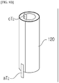
- the first electrode assembly may be deformed in a cylindrical shape so as to constitute an inner cylindrical shape
- the second electrode assembly may surround an outer circumference of the first electrode assembly so as to constitute an outer cylindrical shape
- the lithium secondary battery may further include a cylindrical casing that accommodates the first and second electrode assemblies.
- the positive electrode plate of the first electrode assembly may have a positive electrode current collector onto which any one of LFP, NMC, NCA, and LCO positive electrode active materials is applied, no positive electrode active material may be applied onto the positive electrode tab of the first electrode assembly, and the positive electrode tab of the first electrode assembly may extend from one side of the positive electrode current collector of the first electrode assembly, may be connected to a positive electrode lead tab, and may be used as the positive electrode terminal.
- the negative electrode plate of the first electrode assembly may have a negative electrode current collector onto which an LTO negative electrode active material is applied, no negative electrode active material may be applied onto the serial connection tab of the first electrode assembly, and the serial connection tab of the first electrode assembly may extend from one side of the negative electrode current collector of the first electrode assembly.
- the serial connection tab of the first electrode assembly and the positive electrode tab of the first electrode assembly may be configured so as not to overlap each other.
- the positive electrode plate of the second electrode assembly may have a positive electrode current collector onto which LFP, NMC, NCA, and LCO positive electrode active materials are applied, no positive electrode active material may be applied onto the serial connection tab of the second electrode assembly, and the serial connection tab of the second electrode assembly may extend from one side of the positive electrode current collector of the second electrode assembly.
- serial connection tab of the first electrode assembly and the serial connection tab of the second electrode assembly may overlap each other so as to electrically connect the first electrode assembly and the second electrode assembly.
- the negative electrode plate of the second electrode assembly may have a negative electrode current collector onto which an LTO negative electrode active material is applied, no LTO negative electrode active material may be applied onto the negative electrode tab of the second electrode assembly, and the negative electrode tab of the second electrode assembly may extend from one side of the negative electrode current collector of the second electrode assembly, may be connected to a negative electrode lead tab, and may be used as the negative electrode terminal.
- the positive electrode tab of the first electrode assembly and the negative electrode tab of the second electrode assembly may be configured so as not to overlap each other.
- Each of the negative electrode plate of the first electrode assembly, the positive electrode plate of the first electrode assembly, the negative electrode plate of the second electrode assembly, and the negative electrode plate of the second electrode assembly may include aluminum, stainless steel, or copper.
- the first electrode assembly and the second electrode assembly may be self-balanced by using an LFP positive electrode active material and an LTO negative electrode active material so as to prevent imbalance therebetween.
- the two electrode assemblies are connected by a new type of serial structure, such that the LTO negative electrode, which was restricted in use because of a low voltage thereof, may be used, and thus the lithium secondary battery may has better charging and low-temperature characteristics than a secondary battery made based on graphite in the related art and may solve a problem with safety. Accordingly, the lithium secondary battery may have wide usability in an extreme environment and may have a rated voltage available for a consumer electronic battery.
- the two electrode assemblies use the LFP positive electrode and the LTO negative electrode, it is possible to solve problems of oxidation of an electrolyte due to a relatively low charging voltage(4.2 ⁇ 4.3V, most carbonate solvents starts oxidation around more than 4.5V) and imbalance between the electrode assemblies which occur when the two electrode assemblies or jelly rolls are connected in series in a single cell.
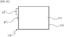
- a lithium secondary battery 100 has excellent charging/discharging characteristics and a rated voltage available for a small-sized battery, and may include a first electrode assembly 110 and a second electrode assembly 120.
- each of the first electrode assembly 110 and the second electrode assembly 120 includes an electrode coated with slurry including an LFP positive electrode active material and an electrode coated with slurry including an LTO negative electrode active material, and the first electrode assembly 110 and the second electrode assembly 120 are stacked on each other with a separation membrane interposed therebetween so that the first electrode assembly 110 and the second electrode assembly 120 are insulated from each other.
- the first electrode assembly 110 and the second electrode assembly 120 are connected to each other by a new type of serial structure through serial connection tabs aT1 and cT2.
- the lithium secondary battery may have a rated voltage of 3.5 to 3.9 V available for general electronic devices (consumer electronics), and the lithium secondary battery is excellent in low-temperature, charging, and lifespan characteristics.
- the stable structure of lithium titanate and the electrochemical characteristics that do not cause lithium plating it is possible to minimize a risk of explosion that may occur due to thermal and mechanical problems.
- a structure for making a single cell by connecting two electrode assemblies in parallel has been generally known and used, but a structure for connecting two electrode assemblies in series is not adapted to a lithium ion battery because of the following two serious problems.
- a carbonate-solvent-based electrolyte (ethylene carbonate, propylene carbonate, dimethyl carbonate, diethyl carbonate, ethyl methyl carbonate, etc.), which is generally and widely used, has the property of being decomposed at a voltage higher than 4.6 V.
- a solid electrolyte or a new ionic liquid needs to be used, but the solid electrolyte or the new ionic liquid has low ion conductivity and is environmentally restricted.
- An electrolyte system which may be substituted for the carbonate-based solvent, has not yet been found.
- one electrode assembly which uses graphite for a negative electrode
- the one electrode assembly typically has a voltage of 3.3 V or more.
- the electrode assemblies In a case in which the one electrode assembly is connected to another electrode assembly (jelly roll) in series, the electrode assemblies have a voltage of 6.6 V or more, and as a result, the electrode assemblies cannot be used for a general electrolyte system.
- the battery having the serial structure is made by using general LCO/Graphite or NMC/Graphite
- connection structure becomes simplified, but when the two electrode assemblies (jelly rolls) are connected in series, a connection structure becomes complicated, and as a result, it is difficult to make the serial structure in the form of a general electrode.
- the lithium secondary battery 100 according to the exemplary embodiment of the present invention adopts a new type of serial structure in order to solve the aforementioned two problems and eliminate the structural complication caused by the serial connection structure.
- the first electrode assembly 110 and the second electrode assembly 120 are stacked and connected by the new type of serial structure, such that the lithium secondary battery 100 has a rated voltage equal to or lower than approximately 4.4 V, particularly, a rated voltage of 3.6 to 3.9 V available for a general small-sized battery, and has excellent charging and low-temperature characteristics, a prolonged lifespan, and mechanical and thermal safety in comparison with a secondary battery in the related art.
- the lithium secondary battery 100 may be used, as an end cell, for general electronic devices (consumer electronics).
- the lithium secondary battery 100 has the property of autonomously adjusting electric potential by using the nature of LFP and LTO materials that cause a rapid change in electric potential at the end of the charging and discharging, and as a result, the lithium secondary battery 100 may minimize the difference in voltage between the first electrode assembly 110 and the second electrode assembly 120 and continuously maintain balance of electric potential between the two electrode assemblies (jelly rolls). As shown in the graph of FIG. 9 , it is possible to minimize a difference in capacity caused by the difference in electric potential between the two electrode assemblies (jelly rolls) during the charging and discharging in comparison with an NMC/Graphite cell.
- the lithium secondary battery 100 in comparison with the case in which the two end cells are simply connected in series, has a configuration in which sizes of terminal tabs of positive and negative electrodes are reduced, a size of a pouch that constitutes a casing is reduced, or the amount of metal is reduced, and as a result, it is possible to reduce costs and increase energy density by approximately 3 %.
- the lithium secondary battery 100 according to the exemplary embodiment of the present invention may be manufactured by a production process in the related art and manufactured in both winding and stacking manners without additional component or instrument.
- first electrode assembly 110 and the second electrode assembly 120 will be described in detail with reference to FIGS. 2A , 2B , 2C , and 5 .
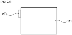
- FIG. 2A is a top plan view of a positive electrode plate (cathode electrode) 111 of the first electrode assembly 110
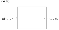
- FIG. 2B is a top plan view of a negative electrode plate (anode electrode) 113 of the first electrode assembly 110
- FIG. 2C is a top plan view illustrating a state in which the positive electrode plate 111 and the negative electrode plate 113 of the first electrode assembly 110 are stacked.
- FIG. 3 is a cross-sectional view of the first electrode assembly 110.
- the first electrode assembly 110 may include the positive electrode plate 111, the negative electrode plate 113, and a separation membrane 115.
- a positive electrode tab cT1 may protrude from a left surface of the positive electrode plate 111.
- the positive electrode tab cT1 may be formed adjacent to an upper side (based on FIG. 3 ) on the left surface of the positive electrode plate 111.
- the serial connection tab aT1 may protrude from a left surface of the negative electrode plate 113.
- the serial connection tab aT1 may be formed at a central portion of the left surface of the negative electrode plate 113.
- the serial connection tab aT1 may be smaller in size than the positive electrode tab cT1.
- the positive electrode plate 111 and the negative electrode plate 113 are stacked.
- the positive electrode tab cT1 and the serial connection tab aT1 do not overlap each other.
- the separation membrane 115 may be provided between the positive electrode plate 111 and the negative electrode plate 113 and may insulate the positive electrode plate 111 and the negative electrode plate 113. This configuration may be ascertained from FIG. 3 .
- the positive electrode plate 111 may include a positive electrode current collector 111a and the positive electrode tab cT1.
- the positive electrode current collector 111a is a part that constitutes a body of the positive electrode plate 111 and may be formed in the form of a quadrangular plate, as illustrated in FIGS. 2A , 2B , and 2C .
- the positive electrode current collector 111a may be made of a material including aluminum or stainless steel.
- Slurry (made by dispersing a positive electrode active material, a binder, and a conductive agent into a solvent) including an LFP positive electrode active material 111b may be applied onto lower and upper surfaces of the positive electrode current collector 111a.
- the LFP positive electrode active material 111b refers to a lithium iron phosphate (LiFePO 4 ) active material.
- the LFP positive electrode active material 111b is a substance that generally forms the positive electrode of the lithium secondary battery, and a detailed description thereof will be omitted.
- the LFP positive electrode active material 111b may be substituted with any one of NMC, NCA, LCO, and LMO positive electrode active materials.
- the positive electrode tab cT1 may extend from the left surface of the positive electrode current collector 111a (based on FIG. 3 ).
- the positive electrode tab cT1 may be made of the same material as the positive electrode current collector 111a. No positive electrode active material is applied onto the positive electrode tab cT1.
- the positive electrode tab cT1 is connected to a lead tab which is a separate conductive connection component, such that the positive electrode tab cT1 may be utilized as a positive electrode terminal of the lithium secondary battery 100.
- the negative electrode plate 113 may include a negative electrode current collector 113a and the serial connection tab aT1.
- the negative electrode current collector 113a is a part that constitutes a body of the negative electrode plate 113 and may be formed in the form of a quadrangular plate similar to the positive electrode current collector 111a.
- the negative electrode current collector 113a may be made of a material including aluminum, copper, or stainless steel.
- Slurry (made by dispersing a negative electrode active material, a binder, and a conductive agent into a solvent) including an LTO negative electrode active material 113b may be applied onto lower and upper surfaces of the negative electrode current collector 113a.
- the LTO negative electrode active material 113b refers to lithium titanium oxide (Li 4 Ti 5 O 12 ). Since the LTO negative electrode active material 113b has been described above, a detailed description thereof will be omitted.
- the serial connection tab aT1 may extend from the left surface of the negative electrode current collector 113a (based on FIG. 3 ).
- the serial connection tab aT1 may be made of the same material as the negative electrode current collector 113a. No negative electrode active material is applied onto the serial connection tab aT1.
- the serial connection tab aT1 may not overlap the positive electrode tab cT1.
- the serial connection tab aT1 may be smaller in size than the positive electrode tab cT1.
- the serial connection tab aT1 is connected directly to a serial connection tab aT2 of the second electrode assembly 120 and serves to connect the first electrode assembly 110 and the second electrode assembly 120 by a new type of serial structure.
- the separation membrane 115 may be provided between the positive electrode plate 111 and the negative electrode plate 113 and may insulate the positive electrode plate 111 and the negative electrode plate 113. That is, the separation membrane 115 may be provided between the LFP positive electrode active material 111b on the lower surface of the positive electrode current collector 111a and the LTO negative electrode active material 113b on the upper surface of the negative electrode current collector 113a.
- the separation membrane 115 electrically separates the positive electrode plate 111 and the negative electrode plate 113 and may allow lithium ions to pass through internal pores of the separation membrane 115.
- the separation membrane 115 is manufactured by using a polyolefin-based (polyethylene or polypropylene) material or non-woven fabric and may include any one of polyvinylidene fluoride, polyethylene oxide, polyacrylonitrile, and polyvinylidene fluoride hexafluoropropylene.
- FIG. 4A is a top plan view of a positive electrode plate 121 of the second electrode assembly 120
- FIG. 4B is a top plan view of a negative electrode plate 123 of the second electrode assembly 120
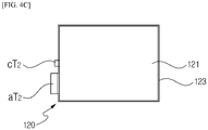
- FIG. 4C is a top plan view illustrating a state in which the positive electrode plate 121 and the negative electrode plate 123 of the second electrode assembly 120 are stacked.
- FIG. 5 is a cross-sectional view of the second electrode assembly 120.
- the second electrode assembly 120 may include the positive electrode plate 121, the negative electrode plate 123, and a separation membrane 125.
- the serial connection tab cT2 may protrude from a left surface of the positive electrode plate 121.
- the connection tab cT2 may be formed at a central portion of the left surface of the positive electrode plate 121.
- the negative electrode tab aT2 may protrude from a left surface of the negative electrode plate 123.
- the negative electrode tab aT2 may be formed adjacent to a lower side (based on FIGS. 4A , 4B , and 4C ) on the left surface of the negative electrode plate 123.
- the negative electrode tab aT2 may be larger in size than the serial connection tab cT2.
- the positive electrode plate 121 and the negative electrode plate 123 are stacked.
- the serial connection tab cT2 and the negative electrode tab aT2 do not overlap each other.
- the separation membrane 125 may be provided between the positive electrode plate 121 and the negative electrode plate 123 and may insulate the positive electrode plate 121 and the negative electrode plate 123. This configuration may be ascertained from FIG. 5 .
- the positive electrode plate 121 may include a positive electrode current collector 121a and the serial connection tab cT2.
- the positive electrode current collector 121a is a part that constitutes a body of the positive electrode plate 121 and may be formed in the form of a quadrangular plate, as illustrated in FIGS. 4A , 4B , and 4C .
- the positive electrode current collector 121a may be made of a material including aluminum or stainless steel.
- Slurry (made by dispersing a positive electrode active material, a binder, and a conductive agent into a solvent) including an LFP positive electrode active material 121b may be applied onto lower and upper surfaces of the positive electrode current collector 121a.
- LFP positive electrode active material 121b is identical to the LFP positive electrode active material 111b applied onto the positive electrode current collector 111a of the first electrode assembly 110, a detailed description thereof will be omitted.
- the serial connection tab cT2 may extend from the left surface of the positive electrode current collector 121a (based on FIG. 5 ).
- the serial connection tab cT2 may be made of the same material as the positive electrode current collector 121a. No positive electrode active material is applied onto the serial connection tab cT2.
- the serial connection tab cT2 may overlap and be joined to the serial connection tab aT1 of the first electrode assembly 110 and may electrically connect the second electrode assembly 120 and the first electrode assembly 110 in series.
- the negative electrode plate 123 may include a negative electrode current collector 123a and the negative electrode tab aT2.
- the negative electrode current collector 123a is a part that constitutes a body of the negative electrode plate 123 and may be formed in the form of a quadrangular plate similar to the positive electrode plate 121.
- the negative electrode current collector 123a may be made of a material including aluminum, copper, or stainless steel.
- Slurry (made by dispersing a negative electrode active material, a binder, and a conductive agent into a solvent) including an LTO negative electrode active material 123b may be applied onto lower and upper surfaces of the negative electrode current collector 123a.
- LTO negative electrode active material 123b is identical to the LTO negative electrode active material 113b applied onto the negative electrode current collector 113a of the first electrode assembly 110, a detailed description thereof will be omitted.
- the negative electrode tab aT2 may extend from the left surface of the negative electrode current collector 123a.
- the negative electrode tab aT2 may be made of the same material as the negative electrode current collector 123a. No negative electrode active material is applied onto the negative electrode tab aT2.
- the negative electrode tab aT2 may not overlap the serial connection tab cT2.
- the negative electrode tab aT2 may be larger in size than the serial connection tab cT2.
- the negative electrode tab aT2 is connected to a lead tab, which is a separate conductive connection component, such that the negative electrode tab aT2 may be utilized as a negative electrode terminal of the lithium secondary battery 100.
- the separation membrane 125 may be provided between the positive electrode plate 121 and the negative electrode plate 123 and may insulate the positive electrode plate 121 and the negative electrode plate 123. That is, the separation membrane 125 may be provided between the LFP positive electrode active material 121b on the lower surface of the positive electrode current collector 121a and the LTO negative electrode active material 123b on the upper surface of the negative electrode current collector 123a.
- the separation membrane 125 may be made of the same material as the aforementioned separation membrane 115 of the first electrode assembly 110.
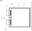
- FIG. 6 is a top plan view of the lithium secondary battery which has an angular (pouch or metal casing) shape and includes the first electrode assembly having the stacking structure and the second electrode assembly having the stacking structure according to the exemplary embodiment of the present invention.
- the first electrode assembly 110 and the second electrode assembly 120 may be stacked with an electrode assembly separation membrane (not illustrated) interposed therebetween.
- the positive electrode plate 111 of the first electrode assembly 110 is disposed at an uppermost end.
- the positive electrode tab cT1 of the first electrode assembly 110 and the serial connection tab cT2 of the second electrode assembly 120 may overlap and be joined to each other, such that the first electrode assembly 110 and the second electrode assembly 120 are connected by a new type of serial structure.
- a quadrangular casing P may accommodate the first electrode assembly 110, the second electrode assembly 120, and the electrode assembly separation membrane.
- examples of the quadrangular casing P may include a pouch, a metal can, and the like.
- the positive electrode tab cT1 is connected to the lead tab which is a separate conductive connection component, such that the positive electrode tab cT1 may protrude to the outside of the quadrangular casing P and may be used as a positive electrode terminal of the lithium secondary battery 100.
- the negative electrode tab aT2 is connected to the lead tab which is a separate conductive connection component, such that the negative electrode tab aT2 may protrude to the outside of the quadrangular casing P and may be used as a negative electrode terminal of the lithium secondary battery 100.
- a liquid electrolyte, a gel type electrolyte such as polymer, or a solid electrolyte may be provided in the quadrangular casing P in order to allow the lithium ions to smoothly move.
- each of the first electrode assembly 110 and the second electrode assembly 120 may be formed to have a jelly roll structure in order to increase a battery capacity.
- the jelly roll structure may be formed by two types of methods.
- the multiple first electrode assemblies 110 and the multiple second electrode assemblies 120 are provided, the multiple first electrode assemblies 110 are stacked on one another with separation membranes interposed therebetween so as to form a jelly roll structure, and the multiple second electrode assemblies 120 are stacked on one another with separation membranes interposed therebetween so as to form a jelly roll structure. Thereafter, the first electrode assembly 110 having the jelly roll structure is stacked on the second electrode assembly 120 having the jelly roll structure with the electrode assembly separation membrane interposed therebetween, and as a result, the lithium secondary battery 110 having an angular (pouch or a metal casing) shape is completely made.
- the second jelly roll structure may be ascertained from the following FIGS. 7A , 7B , and 7C .
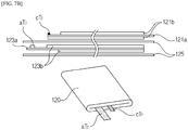
- FIGS. 7A , 7B , and 7C are cross-sectional views and perspective views of the lithium secondary battery which has an angular (pouch or metal casing) shape and includes the first electrode assembly having a winding structure and the second electrode assembly having a winding structure according to the exemplary embodiment of the present invention.
- FIG. 7A is a cross-sectional view and a perspective view of the first electrode assembly having the winding structure
- FIG. 7B is a cross-sectional view and a perspective view of the second electrode assembly having the winding structure
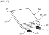
- FIG. 7C is a perspective view of the angular lithium secondary battery having the first electrode assembly stacked on the second electrode assembly.
- the first electrode assembly 110 is wound to form the jelly roll structure, as illustrated in FIG. 7A
- the second electrode assembly 120 is wound to form the jelly roll structure, as illustrated in FIG. 7B .
- the first electrode assembly 110 is stacked on the second electrode assembly 120, the serial connection tabs aT1 and cT2 are coupled to each other, and the first electrode assembly 110 and the second electrode assembly 120 are connected in series, such that the lithium secondary battery 100 may be finally and completely made.
- the positive electrode tab cT1 of the first electrode assembly 110 is connected to a lead tab L1 and used as a positive electrode terminal
- the negative electrode tab aT2 of the second electrode assembly 120 is connected to a lead tab L2 and used as a negative electrode terminal.
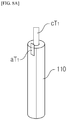
- FIG. 8A is a perspective view of the first electrode assembly 110 that constitutes an inner cylindrical shape of the cylindrical lithium secondary battery 100
- FIG. 8B is a perspective view of the second electrode assembly 120 that constitutes an outer cylindrical shape of the cylindrical lithium secondary battery 100
- FIG. 8C is a perspective view of the cylindrical lithium secondary battery 100.
- the first electrode assembly 110 may constitute the inner cylindrical shape by holding and winding the positive electrode plate, the negative electrode plate, and the separation membrane by using a mandrel.
- the second electrode assembly 120 may constitute the outer cylindrical shape by winding the positive electrode plate, the negative electrode plate, and the separation membrane so that the positive electrode plate, the negative electrode plate, and the separation membrane surround an outer circumference of the first electrode assembly 120.
- the second electrode assembly 120 which constitutes the outer cylindrical shape, surrounds and is coupled to the first electrode assembly 110 which constitutes the inner cylindrical shape, the serial connection tabs aT1 and cT2 are coupled to each other, and the first electrode assembly 110 and the second electrode assembly 120 are connected in series, such that the cylindrical lithium secondary battery 100 may be finally and completely made.
- the negative electrode tab aT2 of the second electrode assembly 120 may be formed in a direction opposite to a direction in which the positive electrode tab cT1 of the first electrode assembly 110, the serial connection tab aT1 of the first electrode assembly, and the serial connection tab cT2 of the second electrode assembly 120 are formed.
- the positive electrode tab cT1 of the first electrode assembly 110, the serial connection tab aT1 of the first electrode assembly 110, and the serial connection tab cT2 of the second electrode assembly 120 may be disposed to protrude from an upper end portion of the cylindrical lithium secondary battery 100, and the positive electrode tab cT1 of the first electrode assembly 110 is connected to an upper cap assembly and forms a positive electrode terminal of the battery.
- the negative electrode tab aT2 of the second electrode assembly 120 is disposed to protrude from a lower end portion of the cylindrical lithium secondary battery 100 and connected to a lower portion of a cylindrical metal can so that the metal can itself forms negative electrode electric potential.
- the cap at the upper side and the metal can at the lower side are insulated by insulating plastic, such that the positive electrode terminal and the negative electrode terminal may be electrically insulated.
- circular protective caps may be coupled to upper and lower ends of the cylindrical lithium secondary battery 100 in order to protect the positive electrode tab cT1 of the first electrode assembly 110, the serial connection tab aT1 of the first electrode assembly 110, the serial connection tab cT2 of the second electrode assembly 120, and the negative electrode tab aT2 of the second electrode assembly 120.
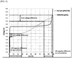
- FIG. 9 is a graph illustrating a concept of self-balancing between the first and second electrode assemblies according to the exemplary embodiment of the present invention.
- FIG. 9 illustrates that the lithium secondary battery (S2 Cell LFP/LTO) 100 according to the exemplary embodiment of the present invention has a concept of self-balancing that inhibits imbalance between the first and second electrode assemblies 110 and 120.
- a difference in voltage of 0.2 V causes a difference in charging capacity of 20%.
- a difference in voltage of 0.2 V causes a difference in charging capacity of 2%. This situation shows that the self-balancing occurs to maximally inhibit a difference in charging amount caused by a rapid change in electric potential at the end of the charging.
- a difference in voltage of 0.1 V causes a difference in discharging capacity of 27%.
- a difference in voltage of 0.1 V causes a difference in discharging capacity of less than 1%. This situation shows that the self-balancing occurs at the end of the discharging.
- the self-balancing occurs at the end of the charging and discharging, thereby minimizing a difference in capacity caused by a difference in voltage between the two electrode assemblies (jelly rolls) in comparison with the NMC/Graphite secondary battery in the related art.
- the lithium secondary battery 100 As shown in Table 1, the lithium secondary battery 100 according to the exemplary embodiment of the present invention has the new type of serial structure in which the serial connection tab aT1 of the first electrode assembly 110 and the serial connection tab cT2 of the second electrode assembly 120 are directly connected, and as a result, it is possible to solve various types of problems that occur when the LTO and the LFP are used as the negative electrode active material and the positive electrode active material, respectively. Therefore, the lithium secondary battery 100 may have a high rated voltage (3.8 V) that may solve the problem caused by a low rated voltage (1.9 to 2.4 V) of the lithium secondary battery that uses the LTO negative electrode active material in the related art.
- the lithium secondary battery 100 may have a higher charging rate (e.g., 5 C) than any type of secondary battery in the related art, have a superior charging performance even at a low temperature, have lifespan characteristics at least three or more times better than a secondary battery in the related art, and exhibit safety without causing thermal runaway even at a high temperature of 300 degrees or more.
- a higher charging rate e.g., 5 C
- FIG. 10 is a graph illustrating capacity retention with respect to charging rates in respect to LTO and graphite utilized as the negative electrode active material of the secondary battery.
- the LTO and the graphite have similar capacity retention in a case in which a specific current of 100 mA/g or less flows when the charging is performed at a low rate (0.5 C or less), but there is a rapid difference in capacity retention when the charging is performed at a high rate (2 C or more), and there is a difference in capacity retention by seven or more times in a case in which a specific current of 1,000 mA/g or more flows.
- the improvement is possible as the battery according to the present invention is used as a secondary battery for solving the aforementioned problem with the rapid charging.
- FIG. 11 is a graph illustrating discharging characteristics with respect to temperatures in respect to a secondary battery in the related art and the lithium secondary battery according to the exemplary embodiment of the present invention.
- an NMC/Graphite secondary battery, an LFP/Graphite secondary battery, and an NMC/LTO secondary battery will be described as an example of the secondary battery in the related art.
- the NMC/Graphite secondary battery, the LFP/Graphite secondary battery, the NMC/LTO secondary battery, and the lithium secondary battery (LFP/LTO) according to the exemplary embodiment of the present invention have discharging rate proximate to 100% at about room temperature, and the discharging performances thereof are decreased as the temperature is decreased.
- the lithium secondary battery (LFP/LTO) according to the exemplary embodiment of the present invention has a discharging rate of approximately 80% at -30°C, such that the lithium secondary battery (LFP/LTO) has better characteristics at a low temperature than the secondary battery in the related art.
- FIG. 12 is a graph illustrating thermal runaway performances in respect to the secondary battery in the related art and the lithium secondary battery according to the exemplary embodiment of the present invention.
- an LCO/Graphite secondary battery, an NMC/Graphite secondary battery, and an LFP/Graphite secondary battery will be described as an example of the secondary battery in the related art.
- the thermal runaway occurs when the temperature reaches approximately 150°C.
- the thermal runaway occurs when the temperature reaches approximately 190°C.
- the thermal runaway occurs when the temperature reaches approximately 230°C.
- the thermal runaway does not occur until the charging temperature reaches 250°C.
- the lithium secondary battery according to the exemplary embodiment of the present invention may be more quickly charged than the secondary battery in the related art, may have better charging and discharging characteristics at a low temperature than the secondary battery in the related art, and may be stronger against heat than the secondary battery in the related art.
- the lithium secondary battery 100 may have excellent temperature and charging/discharging characteristics of the LTO negative electrode active material, may have a rated voltage available for general electronic devices (consumer electronics), and may have structural stability of the LTO negative electrode active material and the electrochemical property of preventing lithium plating, thereby reducing a risk of explosion caused by an increase in temperature. Accordingly, the lithium secondary battery 100 may be applied to various fields including an electricity storage system (ESS), a solar cell, an electric vehicle, an electric bike, and an industrial battery.
- ESS electricity storage system
Landscapes
- Chemical & Material Sciences (AREA)
- Chemical Kinetics & Catalysis (AREA)
- Electrochemistry (AREA)
- General Chemical & Material Sciences (AREA)
- Engineering & Computer Science (AREA)
- Materials Engineering (AREA)
- Inorganic Chemistry (AREA)
- Manufacturing & Machinery (AREA)
- Crystallography & Structural Chemistry (AREA)
- Secondary Cells (AREA)
- Connection Of Batteries Or Terminals (AREA)
Abstract
Description
- The present invention relates to a lithium secondary battery, and particularly, to a lithium secondary battery having excellent charging/discharging characteristics.
- With the development of electric and electronic technologies, the use of portable electronic products, which are small in size and light in weight and have various functions, is rapidly increased. In general, a battery is used as an electric power supply device for operating the portable electronic product, and a secondary battery, which may be reused by being recharged, is often used.
- Examples of the secondary battery in the related art include a lead acid battery, a nickel cadmium (NiCd) battery, a nickel hydrogen (NiMH) battery, a lithium ion (Li-ion) battery, a lithium ion polymer (Li-ion polymer) battery, and a lithium metal battery. The secondary battery offers both economic and environmental advantages in contrast to a primary battery which is discarded after being used once.
- The lithium secondary battery in the related art has positive and negative electrodes each of which has an active material that reversibly intercalates and deintercalates lithium ions, a separation membrane which electrically separates the positive and negative electrodes, and an electrolyte which is interposed between the positive and negative electrodes, and the lithium secondary battery is charged and discharged as the lithium ions move between the electrodes.
- Examples of representative negative electrode active materials include graphite, silicon, silicon composite, and lithium titanate (LTO), and examples of representative positive electrode active materials include lithium cobalt oxide (LCO), lithium nickel manganese cobalt oxide (NMC), lithium nickel oxide (NCA), and lithium iron phosphate (LFP).
- The LTO, which is one of the negative electrode active materials, has a spinel structure and a 3D shape, thus allows free intercalation/deintercalation of lithium ions, and has excellent charging characteristics in comparison with general one-dimensional graphite intercalation.
- The LTO has electric potential of 1.55 V and thus causes no lithium plating, such that there is no safety problem caused by the lithium plating resulting from degradation in cycle life testing that is found in a graphite negative electrode. The LTO doesn't have a solid electrolyte interphase (SEI) film and thus has a lower SEI film resistance value than graphite, such that the LTO has excellent charging/discharging characteristics at a low temperature in addition to the aforementioned excellent structural characteristics.
- In addition, a crystal structure of the LTO less changes during the charging/discharging, and therefore an electrode does not expand or shrink during the charging/discharging but maintains a constant thickness thereof, such that a microstructure of the electrode is constantly maintained without cracks or delamination unlike graphite electrode, and as a result, the LTO exhibits superior cycle life performance in comparison with graphite. Here, the electrode refers to a structure including an active material, a binder, and a conductive agent.
- In addition, the LTO has superior thermal and mechanical stability in comparison with graphite. When an accident happens by an external short-circuit or internal short-circuit which are most common battery failure mode, LTO material itself loses conductivity and transferred to more ceramic-like from the semi-conducting materials, and thus has a mechanism that autonomously makes an cell safe. Therefore, it is possible to prevent ignition or explosion of the cell even in the worst situation.
- Meanwhile, in the case of the lithium secondary battery has produced using a graphite material as a negative electrode, there is a concern about lithium plating, and thereby there is only a method of discarding the lithium secondary battery and then recycling a small amount of metal when recycling the lithium secondary battery. However, in the case of the lithium secondary battery made based on an LTO negative electrode, there is no concern of lithium plating, and therefore various methods may be applied to safely and efficiently recycle desired metals when the lithium secondary battery is recycled. The lithium secondary battery made based on the LTO negative electrode has excellent life cycle performance and environmental merits when we us LFP as a positive electrode because the lithium secondary battery does not include deleterious metal unlike NMC, NCA, and LCO.
- However, the LTO anode based lithium secondary battery has a lower energy density due to the low specific capacity of LTO materials and low cell voltage caused by higher potential of LTO compared to the Graphite based lithium secondary battery..
- Furthermore, a single-cell battery made by coupling a graphite negative electrode and one of various types of positive electrodes, for example, a single-cell battery including an LCO positive electrode and a graphite negative electrode has an average voltage of approximately 3.8 V, and a single-cell battery including an NMC positive electrode and a graphite negative electrode has an average voltage of approximately 3.7 V.
- In contrast, a single-cell battery made by coupling a LTO negative electrode and one of various types of positive electrodes, for example, a single-cell battery including an LCO positive electrode and an LTO negative electrode has an average voltage of approximately 2.4 V, and a single-cell battery including an NMC positive electrode and an LTO negative electrode has an average voltage of approximately 2.3 V.
- As described above, the single-cell battery made based on the LTO negative electrode has a low voltage because of high negative electrode electric potential of the LTO, and as a result, it is difficult to provide an operational voltage window of a general small-sized battery.
- The present invention has been contrived in consideration of the aforementioned situations, and an object of the present invention is to provide a lithium secondary battery which is made based on an LTO negative electrode, has excellent charging/discharging characteristics, a prolonged lifespan, and safety in comparison with a battery in the related art, has a new type of jelly roll serial connection structure, and has a rated voltage available for both small-sized battery and large format battery to reduce the cell cost like packaging and lead tabs .
- To achieve the aforementioned object, a lithium secondary battery according to an exemplary embodiment of the present invention may include: a first electrode assembly which includes a positive" electrode plate having a positive electrode tab that is used as a positive electrode terminal, a negative electrode plate having a serial connection tab, and a separation membrane provided between the positive electrode plate and the negative electrode plate; and a second electrode assembly which is provided to be insulated from the first electrode assembly, in which the second electrode assembly includes a positive electrode plate having a serial connection tab, a negative electrode plate having a negative electrode tab that is used as a negative electrode terminal, and a separation membrane provided between the positive electrode plate and the negative electrode plate, the serial connection tab of the first electrode assembly is connected to the serial connection tab of the second electrode assembly, and the first electrode assembly and the second electrode assembly are connected in series by the serial connection tabs.
- The multiple first electrode assemblies and the multiple second electrode assemblies may be provided so as to increase a battery capacity, the multiple first electrode assemblies may be stacked with the separation membranes interposed therebetween so as to form a jelly roll structure, and the multiple second electrode assemblies may be stacked with the separation membranes interposed therebetween so as to form a jelly roll structure.
- Each of the first electrode assembly and the second electrode assembly may be wound or stack to form a jelly roll structure.
- The first electrode assembly may be disposed to be stacked on the second electrode assembly, and the lithium secondary battery may further include a quadrangular casing that accommodates the first and second electrode assemblies.
- The first electrode assembly may be deformed in a cylindrical shape so as to constitute an inner cylindrical shape, the second electrode assembly may surround an outer circumference of the first electrode assembly so as to constitute an outer cylindrical shape, and the lithium secondary battery may further include a cylindrical casing that accommodates the first and second electrode assemblies.
- The positive electrode plate of the first electrode assembly may have a positive electrode current collector onto which any one of LFP, NMC, NCA, and LCO positive electrode active materials is applied, no positive electrode active material may be applied onto the positive electrode tab of the first electrode assembly, and the positive electrode tab of the first electrode assembly may extend from one side of the positive electrode current collector of the first electrode assembly, may be connected to a positive electrode lead tab, and may be used as the positive electrode terminal.
- The negative electrode plate of the first electrode assembly may have a negative electrode current collector onto which an LTO negative electrode active material is applied, no negative electrode active material may be applied onto the serial connection tab of the first electrode assembly, and the serial connection tab of the first electrode assembly may extend from one side of the negative electrode current collector of the first electrode assembly.
- The serial connection tab of the first electrode assembly and the positive electrode tab of the first electrode assembly may be configured so as not to overlap each other.
- The positive electrode plate of the second electrode assembly may have a positive electrode current collector onto which LFP, NMC, NCA, and LCO positive electrode active materials are applied, no positive electrode active material may be applied onto the serial connection tab of the second electrode assembly, and the serial connection tab of the second electrode assembly may extend from one side of the positive electrode current collector of the second electrode assembly.
- The serial connection tab of the first electrode assembly and the serial connection tab of the second electrode assembly may overlap each other so as to electrically connect the first electrode assembly and the second electrode assembly.
- The negative electrode plate of the second electrode assembly may have a negative electrode current collector onto which an LTO negative electrode active material is applied, no LTO negative electrode active material may be applied onto the negative electrode tab of the second electrode assembly, and the negative electrode tab of the second electrode assembly may extend from one side of the negative electrode current collector of the second electrode assembly, may be connected to a negative electrode lead tab, and may be used as the negative electrode terminal.
- The positive electrode tab of the first electrode assembly and the negative electrode tab of the second electrode assembly may be configured so as not to overlap each other.
- Each of the negative electrode plate of the first electrode assembly, the positive electrode plate of the first electrode assembly, the negative electrode plate of the second electrode assembly, and the negative electrode plate of the second electrode assembly may include aluminum, stainless steel, or copper.
- The first electrode assembly and the second electrode assembly may be self-balanced by using an LFP positive electrode active material and an LTO negative electrode active material so as to prevent imbalance therebetween.
- Therefore, according to the lithium secondary battery according to the exemplary embodiment of the present invention, the two electrode assemblies are connected by a new type of serial structure, such that the LTO negative electrode, which was restricted in use because of a low voltage thereof, may be used, and thus the lithium secondary battery may has better charging and low-temperature characteristics than a secondary battery made based on graphite in the related art and may solve a problem with safety. Accordingly, the lithium secondary battery may have wide usability in an extreme environment and may have a rated voltage available for a consumer electronic battery.
- In addition, since the two electrode assemblies use the LFP positive electrode and the LTO negative electrode, it is possible to solve problems of oxidation of an electrolyte due to a relatively low charging voltage(4.2 ∼ 4.3V, most carbonate solvents starts oxidation around more than 4.5V) and imbalance between the electrode assemblies which occur when the two electrode assemblies or jelly rolls are connected in series in a single cell.
-
-
FIG. 1 is a top plan view of a lithium secondary battery according to an exemplary embodiment of the present invention. -
FIGS. 2A ,2B , and2C are first exploded top plan views illustrating a state in which a first electrode assembly of the lithium secondary battery according to the exemplary embodiment of the present invention is disassembled. -
FIG. 3 is a partially cross-sectional view of the first electrode assembly inFIGS. 2A ,2B , and2C . -
FIG. 4 is a second exploded top plan view illustrating a state in which a second electrode assembly of the lithium secondary battery according to the exemplary embodiment of the present invention is disassembled. -
FIG. 5 is a partially cross-sectional view of the second electrode assembly inFIGS. 4A ,4B , and4C . -
FIG. 6 is a top plan view of the lithium secondary battery which has an angular (pouch or metal casing) shape and includes the first electrode assembly having a stacking structure and the second electrode assembly having a stacking structure according to the exemplary embodiment of the present invention. -
FIGS. 7A ,7B , and7C are cross-sectional views and perspective views of the lithium secondary battery which has an angular (pouch or metal casing) shape and includes the first electrode assembly having a winding structure and the second electrode assembly having a winding structure according to the exemplary embodiment of the present invention. -
FIGS. 8A ,8B , and8C are perspective views of the lithium secondary battery having a cylindrical shape according to the exemplary embodiment of the present invention. -
FIG. 9 is a graph illustrating a concept of self-balancing between the first and second electrode assemblies according to the exemplary embodiment of the present invention. -
FIG. 10 is a graph illustrating capacity retention with respect to charging rates in respect to LTO and graphite. -
FIG. 11 is a graph illustrating discharging characteristics with respect to temperatures in respect to a secondary battery in the related art and the lithium secondary battery according to the exemplary embodiment of the present invention. -
FIG. 12 is a graph illustrating thermal runaway performances in respect to the secondary battery in the related art and the lithium secondary battery according to the exemplary embodiment of the present invention. - In order to sufficiently understand the present invention, advantages in operation of the present invention, and the object to be achieved by carrying out the present invention, reference needs to be made to the accompanying drawings for illustrating an exemplary embodiment of the present invention and contents disclosed in the accompanying drawings.
- Hereinafter, an exemplary embodiment of the present invention will be described in detail with reference to the accompanying drawings. However, the present invention may be modified in various different ways, and is not limited to the exemplary embodiment to be described below. Further, a part irrelevant to the description will be omitted to clearly describe the present invention, and the same constituent elements will be designated by the same reference numerals in the drawings.
- Throughout the specification, unless explicitly described to the contrary, the word "comprise" and variations such as "comprises" or "comprising", will be understood to imply the inclusion of stated elements but not the exclusion of any other elements.
- Referring to
FIG. 1 , a lithiumsecondary battery 100 according to an exemplary embodiment of the present invention has excellent charging/discharging characteristics and a rated voltage available for a small-sized battery, and may include afirst electrode assembly 110 and asecond electrode assembly 120. - According to the lithium
secondary battery 100 according to the exemplary embodiment of the present invention, each of thefirst electrode assembly 110 and thesecond electrode assembly 120 includes an electrode coated with slurry including an LFP positive electrode active material and an electrode coated with slurry including an LTO negative electrode active material, and thefirst electrode assembly 110 and thesecond electrode assembly 120 are stacked on each other with a separation membrane interposed therebetween so that thefirst electrode assembly 110 and thesecond electrode assembly 120 are insulated from each other. Thefirst electrode assembly 110 and thesecond electrode assembly 120 are connected to each other by a new type of serial structure through serial connection tabs aT1 and cT2. Therefore, even though the lithium secondary battery uses the LTO negative electrode active material, the lithium secondary battery may have a rated voltage of 3.5 to 3.9 V available for general electronic devices (consumer electronics), and the lithium secondary battery is excellent in low-temperature, charging, and lifespan characteristics. With the stable structure of lithium titanate and the electrochemical characteristics that do not cause lithium plating, it is possible to minimize a risk of explosion that may occur due to thermal and mechanical problems. - The reason why the new type of serial structure is applied to the lithium
secondary battery 100 according to the exemplary embodiment of the present invention will be described first, and then a configuration of the lithiumsecondary battery 100 according to the exemplary embodiment of the present invention will be described in detail. - A structure for making a single cell by connecting two electrode assemblies in parallel has been generally known and used, but a structure for connecting two electrode assemblies in series is not adapted to a lithium ion battery because of the following two serious problems.
- First, a carbonate-solvent-based electrolyte (ethylene carbonate, propylene carbonate, dimethyl carbonate, diethyl carbonate, ethyl methyl carbonate, etc.), which is generally and widely used, has the property of being decomposed at a voltage higher than 4.6 V. To solve the problem, a solid electrolyte or a new ionic liquid needs to be used, but the solid electrolyte or the new ionic liquid has low ion conductivity and is environmentally restricted. An electrolyte system, which may be substituted for the carbonate-based solvent, has not yet been found. Even though one electrode assembly (jelly roll), which uses graphite for a negative electrode, is applied to any positive electrode system, the one electrode assembly typically has a voltage of 3.3 V or more. In a case in which the one electrode assembly is connected to another electrode assembly (jelly roll) in series, the electrode assemblies have a voltage of 6.6 V or more, and as a result, the electrode assemblies cannot be used for a general electrolyte system.
- Second, there is a problem of imbalance that occurs when two electrode assemblies are connected in series. In a case in which the battery having the serial structure is made by using general LCO/Graphite or NMC/Graphite, there may occur a difference in voltage between the two jelly rolls (electrode assemblies) due to a problem of imbalance between the jelly rolls, and the difference in voltage always overcharges or over discharges one jelly roll, thereby accelerating degradation of the entire end cell.
- It can be seen from
FIG. 9 that in the case of the general NMC/Graphite cell, a difference in charging voltage of 0.2 V causes a difference in charging capacity of 20%. Because the two electrode assemblies are connected in series in the battery, it is difficult for an additional external protective circuit for inhibiting imbalance to be disposed in the battery. It is possible to inhibit the overcharging and over discharging of the electrode assemblies (jelly rolls) by using a chemical method such as a chemical shuttle by means of oxidation and reduction of the chemical shuttle. However, there are problems in that the currently available use range of the chemical shuttle does not exceed 4 V and other performances may deteriorate. - In addition, when the two electrode assemblies (jelly rolls) are connected in parallel, a connection structure becomes simplified, but when the two electrode assemblies (jelly rolls) are connected in series, a connection structure becomes complicated, and as a result, it is difficult to make the serial structure in the form of a general electrode.
- The lithium
secondary battery 100 according to the exemplary embodiment of the present invention adopts a new type of serial structure in order to solve the aforementioned two problems and eliminate the structural complication caused by the serial connection structure. - That is, according to the lithium
secondary battery 100 according to the exemplary embodiment of the present invention, thefirst electrode assembly 110 and thesecond electrode assembly 120, each of which has the LTO negative electrode active material and the LFP positive electrode active material, are stacked and connected by the new type of serial structure, such that the lithiumsecondary battery 100 has a rated voltage equal to or lower than approximately 4.4 V, particularly, a rated voltage of 3.6 to 3.9 V available for a general small-sized battery, and has excellent charging and low-temperature characteristics, a prolonged lifespan, and mechanical and thermal safety in comparison with a secondary battery in the related art. Further, the lithiumsecondary battery 100 may be used, as an end cell, for general electronic devices (consumer electronics). - In addition, the lithium
secondary battery 100 according to the exemplary embodiment of the present invention has the property of autonomously adjusting electric potential by using the nature of LFP and LTO materials that cause a rapid change in electric potential at the end of the charging and discharging, and as a result, the lithiumsecondary battery 100 may minimize the difference in voltage between thefirst electrode assembly 110 and thesecond electrode assembly 120 and continuously maintain balance of electric potential between the two electrode assemblies (jelly rolls). As shown in the graph ofFIG. 9 , it is possible to minimize a difference in capacity caused by the difference in electric potential between the two electrode assemblies (jelly rolls) during the charging and discharging in comparison with an NMC/Graphite cell. - In addition, in comparison with the case in which the two end cells are simply connected in series, the lithium
secondary battery 100 according to the exemplary embodiment of the present invention has a configuration in which sizes of terminal tabs of positive and negative electrodes are reduced, a size of a pouch that constitutes a casing is reduced, or the amount of metal is reduced, and as a result, it is possible to reduce costs and increase energy density by approximately 3 %. - Furthermore, the lithium
secondary battery 100 according to the exemplary embodiment of the present invention may be manufactured by a production process in the related art and manufactured in both winding and stacking manners without additional component or instrument. - Hereinafter, the configurations of the
first electrode assembly 110 and thesecond electrode assembly 120 will be described in detail with reference toFIGS. 2A ,2B ,2C , and5 . - First, the configuration of the
first electrode assembly 110 will be described in detail with reference toFIGS. 2A ,2B ,2C , and3 .FIG. 2A is a top plan view of a positive electrode plate (cathode electrode) 111 of thefirst electrode assembly 110,FIG. 2B is a top plan view of a negative electrode plate (anode electrode) 113 of thefirst electrode assembly 110, andFIG. 2C is a top plan view illustrating a state in which thepositive electrode plate 111 and thenegative electrode plate 113 of thefirst electrode assembly 110 are stacked.FIG. 3 is a cross-sectional view of thefirst electrode assembly 110. - The
first electrode assembly 110 may include thepositive electrode plate 111, thenegative electrode plate 113, and aseparation membrane 115. - In
FIG. 2A , a positive electrode tab cT1 may protrude from a left surface of thepositive electrode plate 111. Here, the positive electrode tab cT1 may be formed adjacent to an upper side (based onFIG. 3 ) on the left surface of thepositive electrode plate 111. - In
FIG. 2B , the serial connection tab aT1 may protrude from a left surface of thenegative electrode plate 113. Here, the serial connection tab aT1 may be formed at a central portion of the left surface of thenegative electrode plate 113. The serial connection tab aT1 may be smaller in size than the positive electrode tab cT1. - It can be ascertained from
FIG. 2C that thepositive electrode plate 111 and thenegative electrode plate 113 are stacked. Here, the positive electrode tab cT1 and the serial connection tab aT1 do not overlap each other. Theseparation membrane 115 may be provided between thepositive electrode plate 111 and thenegative electrode plate 113 and may insulate thepositive electrode plate 111 and thenegative electrode plate 113. This configuration may be ascertained fromFIG. 3 . - Referring to
FIG. 3 , a stacking structure of thefirst electrode assembly 110 may be ascertained. Thepositive electrode plate 111 may include a positive electrodecurrent collector 111a and the positive electrode tab cT1. The positive electrodecurrent collector 111a is a part that constitutes a body of thepositive electrode plate 111 and may be formed in the form of a quadrangular plate, as illustrated inFIGS. 2A ,2B , and2C . The positive electrodecurrent collector 111a may be made of a material including aluminum or stainless steel. - Slurry (made by dispersing a positive electrode active material, a binder, and a conductive agent into a solvent) including an LFP positive electrode
active material 111b may be applied onto lower and upper surfaces of the positive electrodecurrent collector 111a. Here, the LFP positive electrodeactive material 111b refers to a lithium iron phosphate (LiFePO4) active material. The LFP positive electrodeactive material 111b is a substance that generally forms the positive electrode of the lithium secondary battery, and a detailed description thereof will be omitted. In addition, the LFP positive electrodeactive material 111b may be substituted with any one of NMC, NCA, LCO, and LMO positive electrode active materials. - The positive electrode tab cT1 may extend from the left surface of the positive electrode
current collector 111a (based onFIG. 3 ). The positive electrode tab cT1 may be made of the same material as the positive electrodecurrent collector 111a. No positive electrode active material is applied onto the positive electrode tab cT1. The positive electrode tab cT1 is connected to a lead tab which is a separate conductive connection component, such that the positive electrode tab cT1 may be utilized as a positive electrode terminal of the lithiumsecondary battery 100. - The
negative electrode plate 113 may include a negative electrodecurrent collector 113a and the serial connection tab aT1. The negative electrodecurrent collector 113a is a part that constitutes a body of thenegative electrode plate 113 and may be formed in the form of a quadrangular plate similar to the positive electrodecurrent collector 111a. The negative electrodecurrent collector 113a may be made of a material including aluminum, copper, or stainless steel. - Slurry (made by dispersing a negative electrode active material, a binder, and a conductive agent into a solvent) including an LTO negative electrode
active material 113b may be applied onto lower and upper surfaces of the negative electrodecurrent collector 113a. - Here, the LTO negative electrode
active material 113b refers to lithium titanium oxide (Li4Ti5O12). Since the LTO negative electrodeactive material 113b has been described above, a detailed description thereof will be omitted. - The serial connection tab aT1 may extend from the left surface of the negative electrode
current collector 113a (based onFIG. 3 ). The serial connection tab aT1 may be made of the same material as the negative electrodecurrent collector 113a. No negative electrode active material is applied onto the serial connection tab aT1. The serial connection tab aT1 may not overlap the positive electrode tab cT1. The serial connection tab aT1 may be smaller in size than the positive electrode tab cT1. The serial connection tab aT1 is connected directly to a serial connection tab aT2 of thesecond electrode assembly 120 and serves to connect thefirst electrode assembly 110 and thesecond electrode assembly 120 by a new type of serial structure. - The
separation membrane 115 may be provided between thepositive electrode plate 111 and thenegative electrode plate 113 and may insulate thepositive electrode plate 111 and thenegative electrode plate 113. That is, theseparation membrane 115 may be provided between the LFP positive electrodeactive material 111b on the lower surface of the positive electrodecurrent collector 111a and the LTO negative electrodeactive material 113b on the upper surface of the negative electrodecurrent collector 113a. - The
separation membrane 115 electrically separates thepositive electrode plate 111 and thenegative electrode plate 113 and may allow lithium ions to pass through internal pores of theseparation membrane 115. Typically, theseparation membrane 115 is manufactured by using a polyolefin-based (polyethylene or polypropylene) material or non-woven fabric and may include any one of polyvinylidene fluoride, polyethylene oxide, polyacrylonitrile, and polyvinylidene fluoride hexafluoropropylene. - The configuration of the
second electrode assembly 120 will be described in detail with reference toFIGS. 4A ,4B ,4C , and5 .FIG. 4A is a top plan view of apositive electrode plate 121 of thesecond electrode assembly 120,FIG. 4B is a top plan view of anegative electrode plate 123 of thesecond electrode assembly 120, andFIG. 4C is a top plan view illustrating a state in which thepositive electrode plate 121 and thenegative electrode plate 123 of thesecond electrode assembly 120 are stacked.FIG. 5 is a cross-sectional view of thesecond electrode assembly 120. - The
second electrode assembly 120 may include thepositive electrode plate 121, thenegative electrode plate 123, and aseparation membrane 125. - In
FIG. 4A , the serial connection tab cT2 may protrude from a left surface of thepositive electrode plate 121. Here, the connection tab cT2 may be formed at a central portion of the left surface of thepositive electrode plate 121. - In
FIG. 4B , the negative electrode tab aT2 may protrude from a left surface of thenegative electrode plate 123. Here, the negative electrode tab aT2 may be formed adjacent to a lower side (based onFIGS. 4A ,4B , and4C ) on the left surface of thenegative electrode plate 123. The negative electrode tab aT2 may be larger in size than the serial connection tab cT2. - It can be ascertained from
FIG. 4C that thepositive electrode plate 121 and thenegative electrode plate 123 are stacked. Here, the serial connection tab cT2 and the negative electrode tab aT2 do not overlap each other. Theseparation membrane 125 may be provided between thepositive electrode plate 121 and thenegative electrode plate 123 and may insulate thepositive electrode plate 121 and thenegative electrode plate 123. This configuration may be ascertained fromFIG. 5 . - Referring to
FIG. 5 , a stacking structure of thesecond electrode assembly 120 may be ascertained. Thepositive electrode plate 121 may include a positive electrodecurrent collector 121a and the serial connection tab cT2. The positive electrodecurrent collector 121a is a part that constitutes a body of thepositive electrode plate 121 and may be formed in the form of a quadrangular plate, as illustrated inFIGS. 4A ,4B , and4C . The positive electrodecurrent collector 121a may be made of a material including aluminum or stainless steel. - Slurry (made by dispersing a positive electrode active material, a binder, and a conductive agent into a solvent) including an LFP positive electrode
active material 121b may be applied onto lower and upper surfaces of the positive electrodecurrent collector 121a. Here, because the LFP positive electrodeactive material 121b is identical to the LFP positive electrodeactive material 111b applied onto the positive electrodecurrent collector 111a of thefirst electrode assembly 110, a detailed description thereof will be omitted. - The serial connection tab cT2 may extend from the left surface of the positive electrode
current collector 121a (based onFIG. 5 ). The serial connection tab cT2 may be made of the same material as the positive electrodecurrent collector 121a. No positive electrode active material is applied onto the serial connection tab cT2. The serial connection tab cT2 may overlap and be joined to the serial connection tab aT1 of thefirst electrode assembly 110 and may electrically connect thesecond electrode assembly 120 and thefirst electrode assembly 110 in series. - The
negative electrode plate 123 may include a negative electrodecurrent collector 123a and the negative electrode tab aT2. The negative electrodecurrent collector 123a is a part that constitutes a body of thenegative electrode plate 123 and may be formed in the form of a quadrangular plate similar to thepositive electrode plate 121. The negative electrodecurrent collector 123a may be made of a material including aluminum, copper, or stainless steel. - Slurry (made by dispersing a negative electrode active material, a binder, and a conductive agent into a solvent) including an LTO negative electrode
active material 123b may be applied onto lower and upper surfaces of the negative electrodecurrent collector 123a. Here, because the LTO negative electrodeactive material 123b is identical to the LTO negative electrodeactive material 113b applied onto the negative electrodecurrent collector 113a of thefirst electrode assembly 110, a detailed description thereof will be omitted. - The negative electrode tab aT2 may extend from the left surface of the negative electrode
current collector 123a. The negative electrode tab aT2 may be made of the same material as the negative electrodecurrent collector 123a. No negative electrode active material is applied onto the negative electrode tab aT2. The negative electrode tab aT2 may not overlap the serial connection tab cT2. The negative electrode tab aT2 may be larger in size than the serial connection tab cT2. The negative electrode tab aT2 is connected to a lead tab, which is a separate conductive connection component, such that the negative electrode tab aT2 may be utilized as a negative electrode terminal of the lithiumsecondary battery 100. - The
separation membrane 125 may be provided between thepositive electrode plate 121 and thenegative electrode plate 123 and may insulate thepositive electrode plate 121 and thenegative electrode plate 123. That is, theseparation membrane 125 may be provided between the LFP positive electrodeactive material 121b on the lower surface of the positive electrodecurrent collector 121a and the LTO negative electrodeactive material 123b on the upper surface of the negative electrodecurrent collector 123a. Theseparation membrane 125 may be made of the same material as theaforementioned separation membrane 115 of thefirst electrode assembly 110. - It can be ascertained that
FIG. 6 is a top plan view of the lithium secondary battery which has an angular (pouch or metal casing) shape and includes the first electrode assembly having the stacking structure and the second electrode assembly having the stacking structure according to the exemplary embodiment of the present invention. - The
first electrode assembly 110 and thesecond electrode assembly 120 may be stacked with an electrode assembly separation membrane (not illustrated) interposed therebetween. In this case, thepositive electrode plate 111 of thefirst electrode assembly 110 is disposed at an uppermost end. - The positive electrode tab cT1 of the
first electrode assembly 110 and the serial connection tab cT2 of thesecond electrode assembly 120 may overlap and be joined to each other, such that thefirst electrode assembly 110 and thesecond electrode assembly 120 are connected by a new type of serial structure. - A quadrangular casing P may accommodate the
first electrode assembly 110, thesecond electrode assembly 120, and the electrode assembly separation membrane. Here, examples of the quadrangular casing P may include a pouch, a metal can, and the like. - The positive electrode tab cT1 is connected to the lead tab which is a separate conductive connection component, such that the positive electrode tab cT1 may protrude to the outside of the quadrangular casing P and may be used as a positive electrode terminal of the lithium
secondary battery 100. In addition, the negative electrode tab aT2 is connected to the lead tab which is a separate conductive connection component, such that the negative electrode tab aT2 may protrude to the outside of the quadrangular casing P and may be used as a negative electrode terminal of the lithiumsecondary battery 100. A liquid electrolyte, a gel type electrolyte such as polymer, or a solid electrolyte may be provided in the quadrangular casing P in order to allow the lithium ions to smoothly move. - Meanwhile, each of the
first electrode assembly 110 and thesecond electrode assembly 120 may be formed to have a jelly roll structure in order to increase a battery capacity. Here, the jelly roll structure may be formed by two types of methods. - In the case of a first jelly roll structure, the multiple
first electrode assemblies 110 and the multiplesecond electrode assemblies 120 are provided, the multiplefirst electrode assemblies 110 are stacked on one another with separation membranes interposed therebetween so as to form a jelly roll structure, and the multiplesecond electrode assemblies 120 are stacked on one another with separation membranes interposed therebetween so as to form a jelly roll structure. Thereafter, thefirst electrode assembly 110 having the jelly roll structure is stacked on thesecond electrode assembly 120 having the jelly roll structure with the electrode assembly separation membrane interposed therebetween, and as a result, the lithiumsecondary battery 110 having an angular (pouch or a metal casing) shape is completely made. - The second jelly roll structure may be ascertained from the following
FIGS. 7A ,7B , and7C . - It can be ascertained that
FIGS. 7A ,7B , and7C are cross-sectional views and perspective views of the lithium secondary battery which has an angular (pouch or metal casing) shape and includes the first electrode assembly having a winding structure and the second electrode assembly having a winding structure according to the exemplary embodiment of the present invention. -
FIG. 7A is a cross-sectional view and a perspective view of the first electrode assembly having the winding structure,FIG. 7B is a cross-sectional view and a perspective view of the second electrode assembly having the winding structure, andFIG. 7C is a perspective view of the angular lithium secondary battery having the first electrode assembly stacked on the second electrode assembly. - The
first electrode assembly 110 is wound to form the jelly roll structure, as illustrated inFIG. 7A , and thesecond electrode assembly 120 is wound to form the jelly roll structure, as illustrated inFIG. 7B . - As illustrated in
FIG. 7C , thefirst electrode assembly 110 is stacked on thesecond electrode assembly 120, the serial connection tabs aT1 and cT2 are coupled to each other, and thefirst electrode assembly 110 and thesecond electrode assembly 120 are connected in series, such that the lithiumsecondary battery 100 may be finally and completely made. In this case, the positive electrode tab cT1 of thefirst electrode assembly 110 is connected to a lead tab L1 and used as a positive electrode terminal, and the negative electrode tab aT2 of thesecond electrode assembly 120 is connected to a lead tab L2 and used as a negative electrode terminal. - Referring to
FIGS. 8A ,8B , and8C , the cylindrical lithiumsecondary battery 100 may be ascertained.FIG. 8A is a perspective view of thefirst electrode assembly 110 that constitutes an inner cylindrical shape of the cylindrical lithiumsecondary battery 100,FIG. 8B is a perspective view of thesecond electrode assembly 120 that constitutes an outer cylindrical shape of the cylindrical lithiumsecondary battery 100, andFIG. 8C is a perspective view of the cylindrical lithiumsecondary battery 100. - As illustrated in
FIG. 8A , thefirst electrode assembly 110 may constitute the inner cylindrical shape by holding and winding the positive electrode plate, the negative electrode plate, and the separation membrane by using a mandrel. - As illustrated in
FIG. 8B , thesecond electrode assembly 120 may constitute the outer cylindrical shape by winding the positive electrode plate, the negative electrode plate, and the separation membrane so that the positive electrode plate, the negative electrode plate, and the separation membrane surround an outer circumference of thefirst electrode assembly 120. - As illustrated in
FIG. 8C , thesecond electrode assembly 120, which constitutes the outer cylindrical shape, surrounds and is coupled to thefirst electrode assembly 110 which constitutes the inner cylindrical shape, the serial connection tabs aT1 and cT2 are coupled to each other, and thefirst electrode assembly 110 and thesecond electrode assembly 120 are connected in series, such that the cylindrical lithiumsecondary battery 100 may be finally and completely made. - Here, the negative electrode tab aT2 of the
second electrode assembly 120 may be formed in a direction opposite to a direction in which the positive electrode tab cT1 of thefirst electrode assembly 110, the serial connection tab aT1 of the first electrode assembly, and the serial connection tab cT2 of thesecond electrode assembly 120 are formed. - That is, the positive electrode tab cT1 of the
first electrode assembly 110, the serial connection tab aT1 of thefirst electrode assembly 110, and the serial connection tab cT2 of thesecond electrode assembly 120 may be disposed to protrude from an upper end portion of the cylindrical lithiumsecondary battery 100, and the positive electrode tab cT1 of thefirst electrode assembly 110 is connected to an upper cap assembly and forms a positive electrode terminal of the battery. The negative electrode tab aT2 of thesecond electrode assembly 120 is disposed to protrude from a lower end portion of the cylindrical lithiumsecondary battery 100 and connected to a lower portion of a cylindrical metal can so that the metal can itself forms negative electrode electric potential. The cap at the upper side and the metal can at the lower side are insulated by insulating plastic, such that the positive electrode terminal and the negative electrode terminal may be electrically insulated. - Meanwhile, circular protective caps (not illustrated) may be coupled to upper and lower ends of the cylindrical lithium
secondary battery 100 in order to protect the positive electrode tab cT1 of thefirst electrode assembly 110, the serial connection tab aT1 of thefirst electrode assembly 110, the serial connection tab cT2 of thesecond electrode assembly 120, and the negative electrode tab aT2 of thesecond electrode assembly 120. -
FIG. 9 is a graph illustrating a concept of self-balancing between the first and second electrode assemblies according to the exemplary embodiment of the present invention. -
FIG. 9 illustrates that the lithium secondary battery (S2 Cell LFP/LTO) 100 according to the exemplary embodiment of the present invention has a concept of self-balancing that inhibits imbalance between the first andsecond electrode assemblies - Hereinafter, self-balancing characteristics of the lithium
secondary battery 100 according to the exemplary embodiment of the present invention will be described while being compared with an NMC/Graphite secondary battery in the related art. - First, in the case of the NMC/Graphite secondary battery in the related art, a difference in voltage of 0.2 V causes a difference in charging capacity of 20%. In contrast, in the case of the lithium
secondary battery 100 according to the exemplary embodiment of the present invention, a difference in voltage of 0.2 V causes a difference in charging capacity of 2%. This situation shows that the self-balancing occurs to maximally inhibit a difference in charging amount caused by a rapid change in electric potential at the end of the charging. - In addition, in the case of the NMC/Graphite secondary battery in the related art, a difference in voltage of 0.1 V causes a difference in discharging capacity of 27%. In contrast, in the case of the lithium
secondary battery 100 according to the exemplary embodiment of the present invention, a difference in voltage of 0.1 V causes a difference in discharging capacity of less than 1%. This situation shows that the self-balancing occurs at the end of the discharging. - As described above, in the case of the lithium
secondary battery 100 according to the exemplary embodiment of the present invention, the self-balancing occurs at the end of the charging and discharging, thereby minimizing a difference in capacity caused by a difference in voltage between the two electrode assemblies (jelly rolls) in comparison with the NMC/Graphite secondary battery in the related art. - Hereinafter, detailed specifications of the lithium
secondary battery 100 according to the exemplary embodiment of the present invention will be described with reference to Table 1.[Table 1] Battery Type Current Technology Lithium Secondary Battery According to Exemplary Embodiment of Present Invention Lithium Cobalt Oxide Lithium Nickel Manganese Cobalt Oxide Lithium Iron Phosphate Lithium Titanate Rated Voltage (Nominal Voltage) 3.8 V 3.7 V 3.3 V 1.9 V 3.8 V Charging Rate 0.7 C 0.7 C 1 C 5 C 5 C Charging/Discharging Lifespan (Cycle Life) 500 to 1,000 times 1,000 to 2,000 times 1,000 to 2,000 times 3,000 to 7,000 times 3,000 to 7,000 times Thermal Runaway 150°C 190°C 230°C > 300°C > 300°C Application Mobile Computer, Tablet Computer, Laptop Computer, Camera Mobile Device, Electric Vehicle, Industrial Battery Electric Vehicle, Electric Bike, Industrial Battery Electricity Storage System (ESS), Electric Vehicle, Solar Cell Electricity Storage System (ESS), Solar Cell, Electric Vehicle, Electric Bike, Industrial Battery - As shown in Table 1, the lithium
secondary battery 100 according to the exemplary embodiment of the present invention has the new type of serial structure in which the serial connection tab aT1 of thefirst electrode assembly 110 and the serial connection tab cT2 of thesecond electrode assembly 120 are directly connected, and as a result, it is possible to solve various types of problems that occur when the LTO and the LFP are used as the negative electrode active material and the positive electrode active material, respectively. Therefore, the lithiumsecondary battery 100 may have a high rated voltage (3.8 V) that may solve the problem caused by a low rated voltage (1.9 to 2.4 V) of the lithium secondary battery that uses the LTO negative electrode active material in the related art. - In addition, the lithium
secondary battery 100 according to the exemplary embodiment of the present invention may have a higher charging rate (e.g., 5 C) than any type of secondary battery in the related art, have a superior charging performance even at a low temperature, have lifespan characteristics at least three or more times better than a secondary battery in the related art, and exhibit safety without causing thermal runaway even at a high temperature of 300 degrees or more. - A comparison between a performance of the lithium
secondary battery 100 according to the exemplary embodiment of the present invention and a performance of a secondary battery in the related art will be described below with reference toFIGS. 10 to 12 . -
FIG. 10 is a graph illustrating capacity retention with respect to charging rates in respect to LTO and graphite utilized as the negative electrode active material of the secondary battery. - In the graph in
FIG. 10 , the LTO and the graphite have similar capacity retention in a case in which a specific current of 100 mA/g or less flows when the charging is performed at a low rate (0.5 C or less), but there is a rapid difference in capacity retention when the charging is performed at a high rate (2 C or more), and there is a difference in capacity retention by seven or more times in a case in which a specific current of 1,000 mA/g or more flows. The improvement is possible as the battery according to the present invention is used as a secondary battery for solving the aforementioned problem with the rapid charging. -
FIG. 11 is a graph illustrating discharging characteristics with respect to temperatures in respect to a secondary battery in the related art and the lithium secondary battery according to the exemplary embodiment of the present invention. Here, an NMC/Graphite secondary battery, an LFP/Graphite secondary battery, and an NMC/LTO secondary battery will be described as an example of the secondary battery in the related art. - In the graph in
FIG. 11 , the NMC/Graphite secondary battery, the LFP/Graphite secondary battery, the NMC/LTO secondary battery, and the lithium secondary battery (LFP/LTO) according to the exemplary embodiment of the present invention have discharging rate proximate to 100% at about room temperature, and the discharging performances thereof are decreased as the temperature is decreased. In this case, the lithium secondary battery (LFP/LTO) according to the exemplary embodiment of the present invention has a discharging rate of approximately 80% at -30°C, such that the lithium secondary battery (LFP/LTO) has better characteristics at a low temperature than the secondary battery in the related art. -
FIG. 12 is a graph illustrating thermal runaway performances in respect to the secondary battery in the related art and the lithium secondary battery according to the exemplary embodiment of the present invention. Here, an LCO/Graphite secondary battery, an NMC/Graphite secondary battery, and an LFP/Graphite secondary battery will be described as an example of the secondary battery in the related art. - In the graph
FIG. 12 , when analyzing the thermal runaway of the LCO/Graphite secondary battery by increasing a temperature from the room temperature at a rate of 5°C/min, the thermal runaway occurs when the temperature reaches approximately 150°C. - In the case of the NMC/Graphite secondary battery, the thermal runaway occurs when the temperature reaches approximately 190°C.
- In the case of the LFP/Graphite secondary battery, the thermal runaway occurs when the temperature reaches approximately 230°C.
- In contrast, in the case of the lithium secondary battery (LFP/LTO) according to the exemplary embodiment of the present invention, the thermal runaway does not occur until the charging temperature reaches 250°C.
- As described above, the lithium secondary battery according to the exemplary embodiment of the present invention may be more quickly charged than the secondary battery in the related art, may have better charging and discharging characteristics at a low temperature than the secondary battery in the related art, and may be stronger against heat than the secondary battery in the related art.
- Therefore, the lithium
secondary battery 100 according to the exemplary embodiment of the present invention may have excellent temperature and charging/discharging characteristics of the LTO negative electrode active material, may have a rated voltage available for general electronic devices (consumer electronics), and may have structural stability of the LTO negative electrode active material and the electrochemical property of preventing lithium plating, thereby reducing a risk of explosion caused by an increase in temperature. Accordingly, the lithiumsecondary battery 100 may be applied to various fields including an electricity storage system (ESS), a solar cell, an electric vehicle, an electric bike, and an industrial battery. - While the present invention has been described with reference to the exemplary embodiment depicted in the drawings, the exemplary embodiment is described just for illustration, and those skilled in the art will understand that various modifications of the exemplary embodiment and any other exemplary embodiment equivalent thereto are available.
- Accordingly, the true technical protection scope of the present invention should be determined by the technical spirit of the appended claims.
Claims (14)
- A lithium secondary battery comprising:a first electrode assembly which includes a positive electrode plate having a positive electrode tab that is used as a positive electrode terminal, a negative electrode plate having a serial connection tab, and a separation membrane provided between the positive electrode plate and the negative electrode plate; anda second electrode assembly which is provided to be insulated from the first electrode assembly,wherein the second electrode assembly includes a positive electrode plate having a serial connection tab, a negative electrode plate having a negative electrode tab that is used as a negative electrode terminal, and a separation membrane provided between the positive electrode plate and the negative electrode plate, the serial connection tab of the first electrode assembly is connected to the serial connection tab of the second electrode assembly, and the first electrode assembly and the second electrode assembly are connected in series by the serial connection tabs.
- The lithium secondary battery of claim 1, wherein the multiple first electrode assemblies and the multiple second electrode assemblies are provided so as to increase a battery capacity, the multiple first electrode assemblies are stacked with the separation membranes interposed therebetween so as to form a jelly roll structure, and the multiple second electrode assemblies are stacked with the separation membranes interposed therebetween so as to form a jelly roll structure.
- The lithium secondary battery of claim 1, wherein each of the first electrode assembly and the second electrode assembly is wound to form a jelly roll structure.
- The lithium secondary battery of claim 2 or 3, wherein the first electrode assembly is disposed to be stacked on the second electrode assembly, and the lithium secondary battery further includes a quadrangular casing that accommodates the first and second electrode assemblies.
- The lithium secondary battery of claim 2 or 3, wherein the first electrode assembly is deformed in a cylindrical shape so as to constitute an inner cylindrical shape, the second electrode assembly surrounds an outer circumference of the first electrode assembly so as to constitute an outer cylindrical shape, and the lithium secondary battery further includes a cylindrical casing that accommodates the first and second electrode assemblies.
- The lithium secondary battery of claim 2 or 3, wherein the positive electrode plate of the first electrode assembly has a positive electrode current collector onto which any one of LFP, NMC, NCA, and LCO positive electrode active materials is applied, no positive electrode active material is applied onto the positive electrode tab of the first electrode assembly, and the positive electrode tab of the first electrode assembly extends from one side of the positive electrode current collector of the first electrode assembly, is connected to a positive electrode lead tab, and is used as the positive electrode terminal.
- The lithium secondary battery of claim 6, wherein the negative electrode plate of the first electrode assembly has a negative electrode current collector onto which an LTO negative electrode active material is applied, no negative electrode active material is applied onto the serial connection tab of the first electrode assembly, and the serial connection tab of the first electrode assembly extends from one side of the negative electrode current collector of the first electrode assembly.
- The lithium secondary battery of claim 7, wherein the serial connection tab of the first electrode assembly and the positive electrode tab of the first electrode assembly are configured so as not to overlap each other.
- The lithium secondary battery of claim 8, wherein the positive electrode plate of the second electrode assembly has a positive electrode current collector onto which LFP, NMC, NCA, and LCO positive electrode active materials are applied, no positive electrode active material is applied onto the serial connection tab of the second electrode assembly, and the serial connection tab of the second electrode assembly extends from one side of the positive electrode current collector of the second electrode assembly.
- The lithium secondary battery of claim 9, wherein the serial connection tab of the first electrode assembly and the serial connection tab of the second electrode assembly overlap each other so as to electrically connect the first electrode assembly and the second electrode assembly.
- The lithium secondary battery of claim 10, wherein the negative electrode plate of the second electrode assembly has a negative electrode current collector onto which an LTO negative electrode active material is applied, no LTO negative electrode active material is applied onto the negative electrode tab of the second electrode assembly, and the negative electrode tab of the second electrode assembly extends from one side of the negative electrode current collector of the second electrode assembly, is connected to a negative electrode lead tab, and is used as the negative electrode terminal.
- The lithium secondary battery of claim 11, wherein the positive electrode tab of the first electrode assembly and the negative electrode tab of the second electrode assembly are configured so as not to overlap each other.
- The lithium secondary battery of claim 1, wherein each of the negative electrode plate of the first electrode assembly, the positive electrode plate of the first electrode assembly, the negative electrode plate of the second electrode assembly, and the negative electrode plate of the second electrode assembly includes aluminum, stainless steel, or copper.
- The lithium secondary battery of claim 1, wherein the first electrode assembly and the second electrode assembly are self-balanced by using an LFP positive electrode active material and an LTO negative electrode active material so as to prevent imbalance therebetween.
Applications Claiming Priority (3)
| Application Number | Priority Date | Filing Date | Title |
|---|---|---|---|
| KR20160125025 | 2016-09-28 | ||
| KR1020170096954A KR101935229B1 (en) | 2016-09-28 | 2017-07-31 | Lithium secondary battery |
| PCT/KR2017/009397 WO2018062698A1 (en) | 2016-09-28 | 2017-08-29 | Lithium secondary battery |
Publications (2)
| Publication Number | Publication Date |
|---|---|
| EP3522285A1 true EP3522285A1 (en) | 2019-08-07 |
| EP3522285A4 EP3522285A4 (en) | 2020-05-27 |
Family
ID=61977401
Family Applications (1)
| Application Number | Title | Priority Date | Filing Date |
|---|---|---|---|
| EP17856584.2A Pending EP3522285A4 (en) | 2016-09-28 | 2017-08-29 | Lithium secondary battery |
Country Status (2)
| Country | Link |
|---|---|
| EP (1) | EP3522285A4 (en) |
| KR (1) | KR101935229B1 (en) |
Families Citing this family (3)
| Publication number | Priority date | Publication date | Assignee | Title |
|---|---|---|---|---|
| KR102597528B1 (en) | 2018-07-03 | 2023-11-01 | 에스케이온 주식회사 | High voltage battery cell |
| CN114079127A (en) * | 2020-08-11 | 2022-02-22 | 北京小米移动软件有限公司 | Battery pack and terminal |
| KR20220030818A (en) * | 2020-09-03 | 2022-03-11 | 삼성전자주식회사 | Battery and electronic device including battery |
Family Cites Families (8)
| Publication number | Priority date | Publication date | Assignee | Title |
|---|---|---|---|---|
| JP4654575B2 (en) * | 2003-10-27 | 2011-03-23 | パナソニック株式会社 | Cylindrical battery and inter-battery connection structure using the same |
| KR101170881B1 (en) * | 2007-11-17 | 2012-08-03 | 주식회사 엘지화학 | High Power Secondary Battery of Series Connection Structure |
| JP6087489B2 (en) * | 2010-08-20 | 2017-03-01 | 株式会社東芝 | Assembled battery system |
| DE102011088636A1 (en) * | 2011-12-15 | 2013-06-20 | Robert Bosch Gmbh | Hard shell housing with superhydrophobic material |
| KR101669216B1 (en) * | 2013-09-09 | 2016-10-25 | 삼성전자주식회사 | Electrode assembly and secondary battery including the same |
| JP6178183B2 (en) * | 2013-09-17 | 2017-08-09 | 株式会社東芝 | Nonaqueous electrolyte battery, assembled battery and storage battery device |
| US20170025723A1 (en) * | 2014-03-19 | 2017-01-26 | Kabushiki Kaisha Toshiba | Nonaqueous electrolyte secondary battery, assembled battery and battery pack |
| JP2016033898A (en) * | 2014-07-31 | 2016-03-10 | 株式会社東芝 | Nonaqueous electrolyte battery and battery pack |
-
2017
- 2017-07-31 KR KR1020170096954A patent/KR101935229B1/en active IP Right Grant
- 2017-08-29 EP EP17856584.2A patent/EP3522285A4/en active Pending
Also Published As
| Publication number | Publication date |
|---|---|
| KR20180035119A (en) | 2018-04-05 |
| KR101935229B1 (en) | 2019-01-04 |
| EP3522285A4 (en) | 2020-05-27 |
Similar Documents
| Publication | Publication Date | Title |
|---|---|---|
| CN106104901B (en) | Sheet-laminated lithium ion secondary battery and method for manufacturing sheet-laminated lithium ion secondary battery | |
| US10056577B2 (en) | Battery cell of novel structure | |
| US10454140B2 (en) | Electrode body for use in non-aqueous electrolyte secondary battery and non-aqueous electrolyte secondary battery | |
| EP1998401B1 (en) | Electrode assembley and secondary battery using the same | |
| EP2770555B1 (en) | Electrode assembly, battery cell including the electrode assembly, and method of preparing the battery cell | |
| WO2014017864A1 (en) | Secondary battery | |
| JP2007173223A (en) | Battery lamination body and battery pack | |
| EP3522285A1 (en) | Lithium secondary battery | |
| JP4382557B2 (en) | Non-aqueous secondary battery | |
| US20170047576A1 (en) | Secondary battery | |
| KR20200064752A (en) | A positive electrode and an electrode assembly comprising the positive electrode | |
| KR101841306B1 (en) | Electrode assembly comprising dfferent kind of separator comprising taping part for improving safety and lithium secondary batteries comprising the same | |
| US11450910B2 (en) | Secondary battery and insulator for secondary battery | |
| KR20080005631A (en) | Stack and folding-typed electrode assembly capable of preventing internal short to be caused by thermal shrinkage and electrochemical cell containing the same | |
| KR101576597B1 (en) | Secondary battery and battery pack including the same | |
| EP3754749B1 (en) | Secondary battery and battery module | |
| KR20140072794A (en) | Non-aqueous electrolyte rechargeable battery pack | |
| US11476468B2 (en) | Electrode, electrode assembly and method for manufacturing the same | |
| KR20120130557A (en) | Electrode Assembly of Improved Safety And Secondary Battery with the Same | |
| US20200014015A1 (en) | Battery cell and battery having battery cell therein | |
| CN107978761B (en) | Current collector for an energy storage cell for storing electrical energy | |
| JP2005123058A (en) | Nonaqueous electrolyte secondary battery | |
| KR20160043353A (en) | Separator for electrochemical device and electrochemical device comprising the same | |
| KR102479338B1 (en) | Hybrid battery module | |
| US11394093B2 (en) | Secondary battery and battery module |
Legal Events
| Date | Code | Title | Description |
|---|---|---|---|
| STAA | Information on the status of an ep patent application or granted ep patent |
Free format text: STATUS: THE INTERNATIONAL PUBLICATION HAS BEEN MADE |
|
| PUAI | Public reference made under article 153(3) epc to a published international application that has entered the european phase |
Free format text: ORIGINAL CODE: 0009012 |
|
| STAA | Information on the status of an ep patent application or granted ep patent |
Free format text: STATUS: REQUEST FOR EXAMINATION WAS MADE |
|
| 17P | Request for examination filed |
Effective date: 20190412 |
|
| AK | Designated contracting states |
Kind code of ref document: A1 Designated state(s): AL AT BE BG CH CY CZ DE DK EE ES FI FR GB GR HR HU IE IS IT LI LT LU LV MC MK MT NL NO PL PT RO RS SE SI SK SM TR |
|
| AX | Request for extension of the european patent |
Extension state: BA ME |
|
| DAV | Request for validation of the european patent (deleted) | ||
| DAX | Request for extension of the european patent (deleted) | ||
| A4 | Supplementary search report drawn up and despatched |
Effective date: 20200424 |
|
| RIC1 | Information provided on ipc code assigned before grant |
Ipc: H01M 4/485 20100101ALI20200420BHEP Ipc: H01M 2/26 20060101ALI20200420BHEP Ipc: H01M 4/131 20100101ALI20200420BHEP Ipc: H01M 4/136 20100101ALI20200420BHEP Ipc: H01M 4/58 20100101ALI20200420BHEP Ipc: H01M 10/0587 20100101ALI20200420BHEP Ipc: H01M 2/20 20060101ALI20200420BHEP Ipc: H01M 10/0525 20100101AFI20200420BHEP |
|
| STAA | Information on the status of an ep patent application or granted ep patent |
Free format text: STATUS: EXAMINATION IS IN PROGRESS |
|
| 17Q | First examination report despatched |
Effective date: 20210506 |
|
| STAA | Information on the status of an ep patent application or granted ep patent |
Free format text: STATUS: EXAMINATION IS IN PROGRESS |