EP3522002A1 - Calculation processor and calculation method - Google Patents
Calculation processor and calculation method Download PDFInfo
- Publication number
- EP3522002A1 EP3522002A1 EP18154511.2A EP18154511A EP3522002A1 EP 3522002 A1 EP3522002 A1 EP 3522002A1 EP 18154511 A EP18154511 A EP 18154511A EP 3522002 A1 EP3522002 A1 EP 3522002A1
- Authority
- EP
- European Patent Office
- Prior art keywords
- value
- perr
- err
- error
- calculation block
- Prior art date
- Legal status (The legal status is an assumption and is not a legal conclusion. Google has not performed a legal analysis and makes no representation as to the accuracy of the status listed.)
- Granted
Links
Images

Classifications
-
- G—PHYSICS
- G06—COMPUTING OR CALCULATING; COUNTING
- G06F—ELECTRIC DIGITAL DATA PROCESSING
- G06F7/00—Methods or arrangements for processing data by operating upon the order or content of the data handled
- G06F7/38—Methods or arrangements for performing computations using exclusively denominational number representation, e.g. using binary, ternary, decimal representation
- G06F7/48—Methods or arrangements for performing computations using exclusively denominational number representation, e.g. using binary, ternary, decimal representation using non-contact-making devices, e.g. tube, solid state device; using unspecified devices
- G06F7/544—Methods or arrangements for performing computations using exclusively denominational number representation, e.g. using binary, ternary, decimal representation using non-contact-making devices, e.g. tube, solid state device; using unspecified devices for evaluating functions by calculation
- G06F7/552—Powers or roots, e.g. Pythagorean sums
-
- G—PHYSICS
- G06—COMPUTING OR CALCULATING; COUNTING
- G06F—ELECTRIC DIGITAL DATA PROCESSING
- G06F7/00—Methods or arrangements for processing data by operating upon the order or content of the data handled
- G06F7/38—Methods or arrangements for performing computations using exclusively denominational number representation, e.g. using binary, ternary, decimal representation
- G06F7/48—Methods or arrangements for performing computations using exclusively denominational number representation, e.g. using binary, ternary, decimal representation using non-contact-making devices, e.g. tube, solid state device; using unspecified devices
- G06F7/544—Methods or arrangements for performing computations using exclusively denominational number representation, e.g. using binary, ternary, decimal representation using non-contact-making devices, e.g. tube, solid state device; using unspecified devices for evaluating functions by calculation
- G06F7/556—Logarithmic or exponential functions
-
- G—PHYSICS
- G06—COMPUTING OR CALCULATING; COUNTING
- G06F—ELECTRIC DIGITAL DATA PROCESSING
- G06F1/00—Details not covered by groups G06F3/00 - G06F13/00 and G06F21/00
- G06F1/02—Digital function generators
- G06F1/03—Digital function generators working, at least partly, by table look-up
- G06F1/0307—Logarithmic or exponential functions
-
- G—PHYSICS
- G06—COMPUTING OR CALCULATING; COUNTING
- G06F—ELECTRIC DIGITAL DATA PROCESSING
- G06F2101/00—Indexing scheme relating to the type of digital function generated
- G06F2101/08—Powers or roots
-
- G—PHYSICS
- G06—COMPUTING OR CALCULATING; COUNTING
- G06F—ELECTRIC DIGITAL DATA PROCESSING
- G06F2101/00—Indexing scheme relating to the type of digital function generated
- G06F2101/10—Logarithmic or exponential functions
Definitions
- the present disclosure relates to a calculation processor and to a calculation method, each for determining a digital output value from a digital input value based on an exponent value.
- a sensor value as read out from a sensor circuit is processed with a given formula that may include an exponential term in the form of x a with x being an input value and a being an exponent value.
- Such calculations usually are performed with conventional microprocessors having implemented specific standard calculation algorithms or having implemented a look-up table with precalculated values for each possible input value.
- An object to be achieved is to provide an improved calculation concept for determining the value of an exponential function.
- the improved concept comprises a first calculation block for initializing the values for the iterations that are performed in a second calculation block.
- a final calculation block may be implemented for determining an output value from an intermediate value provided by the second calculation block.
- the first calculation block is configured to determine a position number n denoting a position of a Most Significant Bit, MSB, of a significant part of the input value IN.
- MSB Most Significant Bit
- the lowest significant bit, LSB represents a position number 0, such that the highest possible position number would be 7 for an 8-bit input value.
- the position numbers are numbered from 0 to m-1, with m being the word length of the input value.
- the final calculation block is configured to set the output value to the intermediate value y. Accordingly, which each repetition in the second calculation block, the error value err and the intermediate value y are refined based on the actual values of the error value or the power error value perr and on the counter value k . Hence, with each repetition, the error value err converges to a desired final error value while the intermediate value y converges to the exact value of the calculation.
- the exit criterion may be the error value reaching a defined value or range, which could be checked after each iteration step. In such case, the number of iterations may be varying for different input values.
- the exit criterion may be a given number of iterations for the second calculation block such that for each output value, said number of iterations is performed.
- a calculation time for each input value IN or output value is constant. This may be useful if input values are to be processed sequentially, the input values being provided at a given rate.
- the second calculation block is configured to determine the adaptation value as b a / b ⁇ k.
- the second calculation block may comprise an adaptation look-up table and/or a fixed adaptation circuit resulting from a programming in a hardware description language for determining the adaptation value. If implemented with an adaption look-up table, this table only needs a limited number of entries for k from 1 to the maximum number of iterations.
- VHDL very high speed integrated circuit hardware description language
- the first calculation block for setting the intermediate value y comprises an intermediate look-up table and/or a fixed intermediate circuit resulting from a programming in a hardware description language.
- the number of entries is limited to the word length of the input value. The same number of entries could be represented in hardware resulting from the programming in the hardware description language, e.g. VHDL.
- the first calculation block may comprise a barrel shifter for setting the error value err from the input value IN.
- the second calculation block may comprise a 1-bit shifter for setting the error value err to the power error value perr divided by 2.
- the second calculation block comprises a multiplier, in particular a square multiplier or a squaring device, for determining the power error value perr.
- the error threshold equals the base value.
- the second calculation block comprises a comparator for comparing the power error value perr to the error threshold.
- the exit criterion may be fulfilled if the counter value k is equal to or greater than a predefined repetition value L .
- the second calculation block may comprise L-1 instances of respective circuitry, in particular similar circuitry, for each repetition of the increment steps of the counter value k , the determination of the power error value perr and the respective actions if the power error value perr is larger than or equal to the error threshold.
- the second calculation block comprises a further instance of respective circuitry for a final repetition of the increment step of the counter value k and the determination of the power error value perr and the adjustment of the intermediate value y if the power error value perr is larger than or equal to the error threshold.
- the processor may be implemented as an integrated circuit, in particular as an application specific integrated circuit, ASIC, which is free from a microprocessor. Accordingly, all calculations as mentioned above are implemented with specific hardware representations. For example, no software or programming of a microprocessor are needed to perform the calculations mentioned above.
- ASIC application specific integrated circuit
- the base value is chosen fixedly, in particular as 2.
- the exponent value a may also be chosen fixedly for a given desired application.
- values depending on the exponent value a namely the initial intermediate value in the first calculation block and the adaption value in the second calculation block may still be made programmable, e.g. via look-up tables.
- the calculation processor can be directly implemented e.g. on an image sensor providing thousands or millions of sensor values within a limited time frame, i.e. a frame rate of the image sensor.
- a calculation processor can be implemented in the digital data path of image sensors that can be used in film cameras or image cameras (e.g. 4K-HD and others).
- an image sensor arrangement includes in image sensor for providing sensor values from a plurality of image pixels and a calculation processor according to one of the embodiments described above for processing the sensor values, in particular in a serial fashion.
- the improved calculation concept also allows compressing the input data during the calculation, e.g. by loosing or cutting a number of bits. For example, two bits may be intentionally lost with an implementation according to some ITU recommendations.
- the improved calculation concept can also be implemented or described as a calculation method for determining a digital output value from a digital input value IN based on an exponent value a .
- Such method may comprise:
- the adaptation value may be determined as b a / b ⁇ k.
- calculation processor In various applications calculation of an exponential function is necessary.
- a calculation processor will be described that allows the calculation of such exponential values, in particular without the use of a microprocessor.
- One possible but not limiting application for such calculation processor is the gamma calculation with signals in opto-electronic circuits.
- This disclosure is mainly about the pipelined way of calculating the " IN 0.45 " part of this formula.
- the calculation is also known as a "gamma calculation”.
- the pipelined architecture enables a calculation on all the pixels in a serial and/or streamed way, where all calculations will have exactly the same latency.
- the improved calculation concept is not limited to a specific exponent value.
- b may be chosen as an arbitrary value.
- b is chosen as 2, which may be advantageous in view of e.g. binary operations.
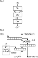
- Figure 1 shows a block diagram of an exemplary implementation of a calculation processor that implements the calculation steps described above.
- the calculation processor comprises a first calculation block CB1 that initializes an intermediate value y and an error value err from the input value IN.
- a second calculation block CB2 iteratively refines these values until an exit criterion is fulfilled.
- a final calculation block CBF determines an output value OUT from the refined intermediate value y' .
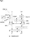
- Figure 2 shows an exemplary implementation of the first calculation block CB1 for implementing the first step of the iterative procedure mentioned above.
- the first step uses the position of the Most Significant Bit, MSB, ("1") of the significant part of the input value IN. It will result in a value for "1 ⁇ err ⁇ 2". Let us call the position of this MSB "n”.
- the input value IN is provided as a binary word, in this example as an 8-bit word.
- the division operations for determining the error value err corresponding to equations (14) or (15) or (16) may be implemented by a shifting operator BLS, which can be embodied as a barrel shifter, for example.
- the shifting is made based on the position number n that can be determined from the actual value of the input value IN. For example the determination of the position number n and the calculation of the initial error value may be seen from the following table 1, which serves as an example for an 8-bit input word.
- Other word lengths undergo the same scheme. For example, all data formats are unsigned integers.
- the letter symbols in the input value IN and the error value err denote arbitrary bit values that particularly have no effect on the determination of the position number n .
- Table 1 IN n err 00000001 0 1.0000000 0000001x 1 1.x000000 000001xy 2 1.xy00000 00001xyz 3 1.xyz0000 0001xyzk 4 1.xyzk000 001xyzkm 5 1.xyzkm00 01xyzkmn 6 1.xyzkmn0 1xyzkmnp 7 1.xyzkmnp
- the values for the intermediate value y according to equation (14) or (15) or (16) may be performed using some kind of memory IMEM that stores the binary value for the respective calculation term.
- the adaptation of the intermediate value y or y' and the error value err or err' are made with respective multiplexers MP1, MP2 providing the respective selected output based on the comparison result.
- the division by two of the power error value or the square error value in equation (29) may for example be performed by a 1-bit shifter when implemented in hardware.
- the multiplication of the previous intermediate value y with an adaptation value by the second multiplier MULT2 can be performed with the adaptation value being retrieved from an adaptation memory AMEM.
- the adaptation memory AMEM may be a look-up table that may be common to different instances CB2_k of the second calculation block CB2, wherein an actual value is retrieved based on the counter value k .
- the adaptation value which is fixed for each iteration stage, may be stored in a fixed adaptation circuit resulting from a programming in a hardware description language like VHDL.
- the intermediate value y' at the output of the calculation instance CB2_k represents the actual approximation of the output value to be calculated according to equation (3).
- the same block could be used physically several times, until a desired number of iterations is performed or until the error value is small enough.
- several instances of the instance CB2_k as shown in Figure 3 could be used with a distinct physical implementation of each instance.
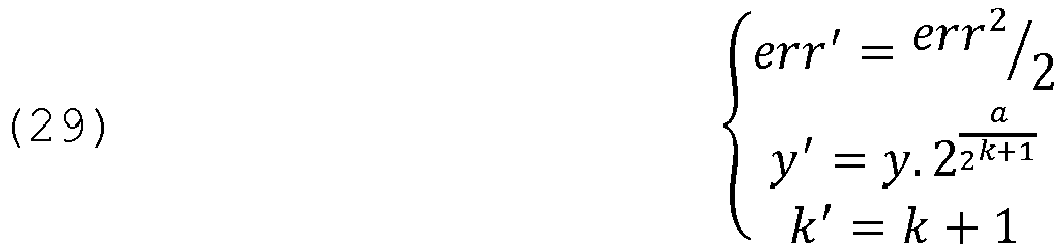
- Figure 4 shows an exemplary implementation of a calculation processor according to the improved calculation concept that implements the latter mentioned approach.
- the second calculation block CB2 may be implemented with a predefined number L instances of calculation instances CB2_1, CB2_2 to CB2_L as described in conjunction with Figure 3 .
- the blocks concerning the update of the error value err' in particular blocks OBS and MP2 can be omitted, as only the intermediate value y' is needed as an output.
- the last instance can directly be used also as the final calculation block CBF for generating the output value OUT.
- such a calculation processor can be directly implemented e.g. on an image sensor providing thousands or millions of sensor values within a limited time frame, i.e. a frame rate of the image sensor.
- a calculation processor can be implemented in the digital data path of image sensors that can be used in film cameras or image cameras (e.g. 4K-HD and others).
- the calculation processor allows processing of a large amount of data, i.e. pixels of an image processor that are provided as a serial readout such that the calculations can be performed very fast in order not to reduce the output speed, and as such not reduce the frame rate of the sensor on which the calculation processor is implemented.
- the serial treatment of the pixels takes benefit of such a calculation processor with a predefined latency, in order to make serial calculations possible, at a speed which can be the transmission speed of the samples.
- the calculations that may be necessary according to the ITU recommendations can be performed directly on the sensor chip and do not need to be performed outside the sensor chip, e.g. on a dedicated image processor.
- the various implementations may be implemented as integrated circuits, in particular as application-specific integrated circuits, ASICs, such that no microprocessor is needed for performing the respective calculations.
- the respective binary representations of the adaption values and the initial intermediate values can be determined in advance and provided hardcoded, i.e. as hardware into the circuit.
- step a) the position number n is determined as a function of the input value IN, in particular denoting the position of the MSB of a significant part of the input value IN. This has for example been described in conjunction with table 1 above.
- step b) an initial value for the intermediate value y is determined in accordance with the calculation in equation (16). With the base value b chosen as 2, also equation (14) applies.
- step c) the initial error value is set in accordance with equation (16) or (14), if the base value is 2.
- step d) a counter value k is initialized, for example to 0.
- steps e), f), g1), g2), g3), g4) are performed iteratively and/or repeatedly.
- step e the counter value k is incremented by 1.
- step f a power error value is determined. If the base value is 2, the power error value is a square error value. If the power error value or square value is larger than an error threshold, in particular the base value b , the intermediate value y1 is set to the previous intermediate value y multiplied with an adaptation value ADPT being dependent on the counter value k . This is for example described in conjunction with equation (29). Furthermore, in step g2), the new error value err' is set to the power error value divided by the base value b .
- the new error value err' is set to the power error value perr in step g3).
- the new intermediate value y ' is set to the old intermediate value y .
- Step g4) is optional as in fact no change to the value y is made.
- the last intermediate value y' is set as the output value OUT in step h). If not, the previous steps are repeated with the error value err being err' and the intermediate value y being y' .
Landscapes
- Engineering & Computer Science (AREA)
- Physics & Mathematics (AREA)
- General Physics & Mathematics (AREA)
- Theoretical Computer Science (AREA)
- Pure & Applied Mathematics (AREA)
- Mathematical Analysis (AREA)
- Computational Mathematics (AREA)
- Computing Systems (AREA)
- Mathematical Optimization (AREA)
- General Engineering & Computer Science (AREA)
- Complex Calculations (AREA)
- Power Sources (AREA)
- Studio Devices (AREA)
Abstract
Description
- The present disclosure relates to a calculation processor and to a calculation method, each for determining a digital output value from a digital input value based on an exponent value.
- In several applications, in particular sensor applications, continuous processing of the sensor signal is necessary. For example, some applications or standards require that a sensor value as read out from a sensor circuit is processed with a given formula that may include an exponential term in the form of xa with x being an input value and a being an exponent value.
- Such calculations usually are performed with conventional microprocessors having implemented specific standard calculation algorithms or having implemented a look-up table with precalculated values for each possible input value.
- While the latter approach requires a large amount of memory and/or area on a semiconductor die, the speed of microprocessor calculation algorithms may be insufficient and/or arbitrary.
- An object to be achieved is to provide an improved calculation concept for determining the value of an exponential function.
- This object is achieved with the subject matter of the independent claims. Embodiments and developments of the improved concept are defined in the dependent claims.
- The improved calculation concept is based on the idea that an error factor can be introduced into a representation of an exponential function in the form of

- For example, the improved concept comprises a first calculation block for initializing the values for the iterations that are performed in a second calculation block. A final calculation block may be implemented for determining an output value from an intermediate value provided by the second calculation block.
- For example, a calculation processor according to the improved calculation concept for determining a digital output value from a digital input value IN based on an exponent value a comprises the first calculation block, the second calculation block and the final calculation block. The first calculation block is configured to determine a position number n denoting a position of a Most Significant Bit, MSB, of a significant part of the input value IN. For example, the lowest significant bit, LSB, represents a
position number 0, such that the highest possible position number would be 7 for an 8-bit input value. Generally, the position numbers are numbered from 0 to m-1, with m being the word length of the input value. - The first calculation block is further configured to set an intermediate value y = ba·n with b being a base value, to set an error value err =IN/bn and initialize a counter value k. For example, the counter value k is initialized to k = 0.
- The second calculation block is configured to perform each of the following until an exit criterion is fulfilled: Increment the counter value k by 1, determine a power error value perr with perr = errb. If the power error value perr is larger than or equal to an error threshold, adjust the intermediate value y by multiplying the intermediate value with an adaptation value being dependent on the counter value k. If the power error value perr is larger than or equal to the error threshold, set the error value err to the power error value perr divided by the base value b. If the power error value perr is smaller than the error threshold, set the error value err to the power error value perr.
- The final calculation block is configured to set the output value to the intermediate value y. Accordingly, which each repetition in the second calculation block, the error value err and the intermediate value y are refined based on the actual values of the error value or the power error value perr and on the counter value k. Hence, with each repetition, the error value err converges to a desired final error value while the intermediate value y converges to the exact value of the calculation.
- The exit criterion may be the error value reaching a defined value or range, which could be checked after each iteration step. In such case, the number of iterations may be varying for different input values.
- In some implementations, the exit criterion may be a given number of iterations for the second calculation block such that for each output value, said number of iterations is performed. In such an implementation, a calculation time for each input value IN or output value is constant. This may be useful if input values are to be processed sequentially, the input values being provided at a given rate.
- For example, the second calculation block is configured to determine the adaptation value as ba /b^k. The second calculation block may comprise an adaptation look-up table and/or a fixed adaptation circuit resulting from a programming in a hardware description language for determining the adaptation value. If implemented with an adaption look-up table, this table only needs a limited number of entries for k from 1 to the maximum number of iterations.
- If, for example, implemented as an application-specific integrated circuit, ASIC, the same limited number of adaption values could be represented as fixed hardware values that may result from the programming in the hardware description language, for example in the very high speed integrated circuit hardware description language known as VHDL.
- In a similar fashion, in some implementations the first calculation block for setting the intermediate value y comprises an intermediate look-up table and/or a fixed intermediate circuit resulting from a programming in a hardware description language. In an implementation with the look-up table, the number of entries is limited to the word length of the input value. The same number of entries could be represented in hardware resulting from the programming in the hardware description language, e.g. VHDL.
- While the improved calculation concept generally works with any base value b, several advantages arise, in particular with respect to implementation of binary number representation, if the base value is chosen as 2. For example, in such implementations where the base value is 2, the first calculation block may comprise a barrel shifter for setting the error value err from the input value IN. In particular, the resulting division err = IN divided by 2 n , i.e. err = IN/2 n can be implemented by an n-times shift operation.
- In a similar fashion, with the base value being 2 the second calculation block may comprise a 1-bit shifter for setting the error value err to the power error value perr divided by 2.
- Also determining the power error value can be simplified by using 2 as the base value. For example, the second calculation block comprises a multiplier, in particular a square multiplier or a squaring device, for determining the power error value perr.
- In various implementations the error threshold equals the base value.
- In some implementations the second calculation block comprises a comparator for comparing the power error value perr to the error threshold.
- As mentioned above, the exit criterion may be fulfilled if the counter value k is equal to or greater than a predefined repetition value L. In such an implementation, the second calculation block may comprise L-1 instances of respective circuitry, in particular similar circuitry, for each repetition of the increment steps of the counter value k, the determination of the power error value perr and the respective actions if the power error value perr is larger than or equal to the error threshold. Furthermore, the second calculation block comprises a further instance of respective circuitry for a final repetition of the increment step of the counter value k and the determination of the power error value perr and the adjustment of the intermediate value y if the power error value perr is larger than or equal to the error threshold. The implementation with distinct instances for each repetition step assures that a calculation time for each input value or output value remains constant, in particular independently from usually varying input values. This can be further useful when processing sequences of input values with a fixed data rate.
- In various implementations the processor may be implemented as an integrated circuit, in particular as an application specific integrated circuit, ASIC, which is free from a microprocessor. Accordingly, all calculations as mentioned above are implemented with specific hardware representations. For example, no software or programming of a microprocessor are needed to perform the calculations mentioned above.
- With implementation as an integrated circuit, it is assumed that the base value is chosen fixedly, in particular as 2. Furthermore, the exponent value a may also be chosen fixedly for a given desired application. However, as mentioned above, values depending on the exponent value a, namely the initial intermediate value in the first calculation block and the adaption value in the second calculation block may still be made programmable, e.g. via look-up tables.
- In various implementations the calculation processor can be directly implemented e.g. on an image sensor providing thousands or millions of sensor values within a limited time frame, i.e. a frame rate of the image sensor. Generally speaking, such a calculation processor can be implemented in the digital data path of image sensors that can be used in film cameras or image cameras (e.g. 4K-HD and others).
- Hence according to the improved calculation concept, an image sensor arrangement is provided that includes in image sensor for providing sensor values from a plurality of image pixels and a calculation processor according to one of the embodiments described above for processing the sensor values, in particular in a serial fashion.
- The improved calculation concept also allows compressing the input data during the calculation, e.g. by loosing or cutting a number of bits. For example, two bits may be intentionally lost with an implementation according to some ITU recommendations.
- The improved calculation concept can also be implemented or described as a calculation method for determining a digital output value from a digital input value IN based on an exponent value a. Such method may comprise:
- a) determine a position number n denoting a position of a Most Significant Bit, MSB, of a significant part of the input value IN;
- b) set an intermediate value y = ba·n with b being a base value;
- c) set an error value err = IN/bn ;
- d) initialize a counter value k;
the method further comprising performing repeatedly each of the steps e), f), g1), g2), g3) until an exit criterion is fulfilled: - e) increment the counter value k by 1;
- f) determine a power error value perr with perr = errb;
- g1) if the power error value perr is larger than or equal to an error threshold, adjust the intermediate value y by multiplying the intermediate value y with an adaptation value being dependent on the counter value k;
- g2) if the power error value perr is larger than or equal to the error threshold, set the error value err to the power error value perr divided by the base value b;
- g3) if the power error value perr is smaller than the error threshold, set the error value err to the power error value perr;
- h) set the output value (OUT) to the intermediate value y.
- As mentioned above, the adaptation value may be determined as ba /b^k.
- Further implementations of the calculation method become readily apparent for the skilled person from the various descriptions made with respect to the embodiments of the calculation processor.
- The improved concept will be described in more detail in the following with the aid of drawings. Elements having the same or similar function bear the same reference numerals throughout the drawings. Hence their description is not necessarily repeated in subsequent drawings.
- In the drawings:
- Figure 1
- shows a block diagram of an exemplary implementation of a calculation processor according to the improved calculation concept;
- Figure 2
- shows an exemplary implementation of a first calculation block;
- Figure 3
- shows an exemplary implementation of a repetition instance in the second calculation block;
- Figure 4
- shows a block diagram of a further implementation of a calculation processor; and
- Figure 5
- shows a block diagram of an exemplary implementation of a calculation method according to the improved calculation concept.
- In various applications calculation of an exponential function is necessary. In the following, a calculation processor will be described that allows the calculation of such exponential values, in particular without the use of a microprocessor. One possible but not limiting application for such calculation processor is the gamma calculation with signals in opto-electronic circuits.
- For example, the calculation processor is used as a or in a circuit that can calculate the opto-electronic transfer characteristics of image pixels, according to recommendations ITU-R BT.709-6, ITU-R BT.2020-2 and ITU-R BT.2100-0, and all associated types of calculations. These specifications do require the calculation of:

- This disclosure is mainly about the pipelined way of calculating the "IN 0.45" part of this formula. The calculation is also known as a "gamma calculation". The pipelined architecture enables a calculation on all the pixels in a serial and/or streamed way, where all calculations will have exactly the same latency.
- Hence, the value to be calculated in particular is:

- Equation (3) can also be written as:


- An "error" factor err can be introduced in the formulas (4) or (5) from above. The formula is still correct when we write the following:

- In practice this form of the formula leaves the possibility to start with a value for y of which we know that it is wrong (in practice it may be put to "1"), but which is gradually adapted in an iterative way. So step by step, y will evolve into xa , while err will go from xa to 1, using e.g. ASIC friendly calculation techniques. These steps can be implemented in the hardware. So:

-
Figure 1 shows a block diagram of an exemplary implementation of a calculation processor that implements the calculation steps described above. For example, the calculation processor comprises a first calculation block CB1 that initializes an intermediate value y and an error value err from the input value IN. A second calculation block CB2 iteratively refines these values until an exit criterion is fulfilled. A final calculation block CBF determines an output value OUT from the refined intermediate value y'. - The individual calculation blocks CB1, CB2 and CBF will be described in more detail in the following in conjunction with
Figure 2 ,Figure 3 andFigure 4 . -
Figure 2 shows an exemplary implementation of the first calculation block CB1 for implementing the first step of the iterative procedure mentioned above. - The first step uses the position of the Most Significant Bit, MSB, ("1") of the significant part of the input value IN. It will result in a value for "1 ≤ err < 2". Let us call the position of this MSB "n".
- With the starting positions of "err" and "y",



- It should be noted that for an arbitrarily chosen base value b, equation (14) reads:

- Referring to equation (8) and with x=IN, the error value err and the intermediate value y after the first step or the first calculation block CB1 hence can be generally determined as:

- Then:

- So the new formula to work with becomes:

- Referring to
Figure 2 , the input value IN is provided as a binary word, in this example as an 8-bit word. The division operations for determining the error value err corresponding to equations (14) or (15) or (16) may be implemented by a shifting operator BLS, which can be embodied as a barrel shifter, for example. The shifting is made based on the position number n that can be determined from the actual value of the input value IN. For example the determination of the position number n and the calculation of the initial error value may be seen from the following table 1, which serves as an example for an 8-bit input word. Other word lengths undergo the same scheme. For example, all data formats are unsigned integers. The letter symbols in the input value IN and the error value err denote arbitrary bit values that particularly have no effect on the determination of the position number n.Table 1: IN n err 00000001 0 1.0000000 0000001x 1 1.x000000 000001xy 2 1.xy00000 00001xyz 3 1.xyz0000 0001xyzk 4 1.xyzk000 001xyzkm 5 1.xyzkm00 01xyzkmn 6 1.xyzkmn0 1xyzkmnp 7 1.xyzkmnp - The values for the intermediate value y according to equation (14) or (15) or (16) may be performed using some kind of memory IMEM that stores the binary value for the respective calculation term.
- As an example, this is shown in table 2 below. The column on the far right shows the initial intermediate values with 4 bits before and 2 bits behind the digital point, as an example. Other number formats still may be used, which should be apparent to the skilled reader.
- The position of the digital point in
Figure 2 is for calculation purposes only. It can, for example in a later stage, be moved in order to fit the result to a required number of output bits, suitable for the desired application.Table 2: n a a.n 2^ (a.n) binary(4+2) 0 0.45 0 1 0001.00 1 0.45 0.45 1.366040257 0001.01 2 0.45 0.9 1.866065983 0001.11 3 0.45 1.35 2.549121255 0010.10 4 0.45 1.8 3.482202253 0011.01 5 0.45 2.25 4.75682846 0100.11 6 0.45 2.7 6.498019171 0110.01 7 0.45 3.15 8.876555777 1000.11 - From now on a sequence of identical or quasi-identical steps has to be performed until "err = 1" or until "err" is small enough. The exact number can be subject of a case-specific simulation. The steps are numbered by "k", starting from 0.
- Referring now to
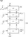
Figure 3 , an exemplary implementation of one calculation instance CB2_k is shown that performs the respective calculations of step k. - The distinguishing is made based on a power error value perr that generally is determined as perr = errb , which is perr = err2 for the specific implementation with the base value being 2. Referring to
Figure 3 , this is implemented with a multiplier MULT1 for performing the power operation or square operation. The result of this operation is compared to an error threshold with comparator COMP. In a specific implementation the error threshold equals the base value, which is 2 in the specific example. - The input from the previous step k is of the form:


- For the actual step, k is incremented by 1. Now, for the approximation, two cases have to be distinguished.
- So, when "err2 < 2", after "k" iterations, then:

- New values for the following step:


- Or:

- So, in this case, after "k" iterations:



- Or:

- The adaptation of the intermediate value y or y' and the error value err or err' are made with respective multiplexers MP1, MP2 providing the respective selected output based on the comparison result.
- The division by two of the power error value or the square error value in equation (29) may for example be performed by a 1-bit shifter when implemented in hardware.
- The multiplication of the previous intermediate value y with an adaptation value by the second multiplier MULT2 can be performed with the adaptation value being retrieved from an adaptation memory AMEM. The adaptation memory AMEM may be a look-up table that may be common to different instances CB2_k of the second calculation block CB2, wherein an actual value is retrieved based on the counter value k. In an alternative implementation, the adaptation value, which is fixed for each iteration stage, may be stored in a fixed adaptation circuit resulting from a programming in a hardware description language like VHDL. The intermediate value y' at the output of the calculation instance CB2_k represents the actual approximation of the output value to be calculated according to equation (3).
- In a hardware implementation, the same block could be used physically several times, until a desired number of iterations is performed or until the error value is small enough. However, in some implementations, several instances of the instance CB2_k as shown in
Figure 3 could be used with a distinct physical implementation of each instance. - For example,
Figure 4 shows an exemplary implementation of a calculation processor according to the improved calculation concept that implements the latter mentioned approach. - Accordingly, the calculation processor comprises the first calculation block CB1 that may be implemented as shown in
Figure 2 for providing initial values for the intermediate value y and the error value err from the input value IN, denoting the stage k = 0. - The second calculation block CB2 may be implemented with a predefined number L instances of calculation instances CB2_1, CB2_2 to CB2_L as described in conjunction with
Figure 3 . However, for the last stage CB2_L the blocks concerning the update of the error value err', in particular blocks OBS and MP2 can be omitted, as only the intermediate value y' is needed as an output. - Moreover, the last instance can directly be used also as the final calculation block CBF for generating the output value OUT.
- Referring to
Figure 4 , the calculation block instances with k = 1 to L are provided with respective adaptation values, which are fixed values for each stage. - It should be noted that the implementation according to
Figure 4 realizes a pipelined architecture that enables processing of sequential input values in a serial or streamed way, wherein all calculations between input and output have the same latency. - As mentioned above, if the calculation processor is used for a gamma calculation according to equation (2), an additional multiplier and an additional subtractor could also be easily added to the implementation of
Figure 4 . - Moreover, such a calculation processor can be directly implemented e.g. on an image sensor providing thousands or millions of sensor values within a limited time frame, i.e. a frame rate of the image sensor. Generally speaking, such a calculation processor can be implemented in the digital data path of image sensors that can be used in film cameras or image cameras (e.g. 4K-HD and others).
- Accordingly, the calculation processor according to the improved calculation concept allows processing of a large amount of data, i.e. pixels of an image processor that are provided as a serial readout such that the calculations can be performed very fast in order not to reduce the output speed, and as such not reduce the frame rate of the sensor on which the calculation processor is implemented.
- The serial treatment of the pixels takes benefit of such a calculation processor with a predefined latency, in order to make serial calculations possible, at a speed which can be the transmission speed of the samples. Hence, the calculations that may be necessary according to the ITU recommendations can be performed directly on the sensor chip and do not need to be performed outside the sensor chip, e.g. on a dedicated image processor.
- The various implementations may be implemented as integrated circuits, in particular as application-specific integrated circuits, ASICs, such that no microprocessor is needed for performing the respective calculations.
- The respective binary representations of the adaption values and the initial intermediate values can be determined in advance and provided hardcoded, i.e. as hardware into the circuit.
- Referring now to
Figure 5 , a block diagram of an exemplary embodiment of a calculation method according to the improved calculation concept is shown. In step a), the position number n is determined as a function of the input value IN, in particular denoting the position of the MSB of a significant part of the input value IN. This has for example been described in conjunction with table 1 above. - In step b) an initial value for the intermediate value y is determined in accordance with the calculation in equation (16). With the base value b chosen as 2, also equation (14) applies.
- In step c) the initial error value is set in accordance with equation (16) or (14), if the base value is 2.
- In step d) a counter value k is initialized, for example to 0.
- The following steps e), f), g1), g2), g3), g4) are performed iteratively and/or repeatedly.
- For example, in step e), the counter value k is incremented by 1. In step f), a power error value is determined. If the base value is 2, the power error value is a square error value. If the power error value or square value is larger than an error threshold, in particular the base value b, the intermediate value y1 is set to the previous intermediate value y multiplied with an adaptation value ADPT being dependent on the counter value k. This is for example described in conjunction with equation (29). Furthermore, in step g2), the new error value err' is set to the power error value divided by the base value b.
- If the power error value perr is smaller than the error threshold or the base value, the new error value err' is set to the power error value perr in step g3). In optional step g4), the new intermediate value y' is set to the old intermediate value y. Step g4) is optional as in fact no change to the value y is made.
- If an exit criterion is fulfilled, the last intermediate value y' is set as the output value OUT in step h). If not, the previous steps are repeated with the error value err being err' and the intermediate value y being y'.
- It should be noted that with the description of the method of
Figure 5 , only the elementary steps have been described. However, both the mathematics and the specific implementation of the method should be apparent for the skilled reader from the detailed description above in conjunction withFigures 1 to 4 .
Claims (15)
- A calculation processor for determining a digital output value (OUT) from a digital input value (IN) based on an exponent value a, the processor comprising- a first calculation block (CB1) that is configured to:a) determine a position number n denoting a position of a Most Significant Bit, MSB, of a significant part of the input value IN;b) set an intermediate value y = ba·n with b being a base value;c) set an error value err = IN/bn; andd) initialize a counter value k;- a second calculation block (CB2) that is configured to perform repeatedly each of the following steps? until an exit criterion is fulfilled:e) increment the counter value k by 1;f) determine a power error value perr with perr = errb;g1) if the power error value perr is larger than or equal to an error threshold, adjust the intermediate value y by multiplying the intermediate value y with an adaptation value being dependent on the counter value k;g2) if the power error value perr is larger than or equal to the error threshold, set the error value err to the power error value perr divided by the base value b;g3) if the power error value perr is smaller than the error threshold, set the error value err to the power error value perr;
and- a final calculation block (CBF) that is configured to set the output value (OUT) to the intermediate value y. - The processor according to claim 1, wherein the second calculation block (CB2) is configured to determine the adaptation value as ba /b^k.
- The processor according to claim 2, wherein the second calculation block (CB2) comprises an adaptation look-up table and/or a fixed adaptation circuit resulting from a programming in a hardware description language for determining the adaptation value.
- The processor according to one of claims 1 to 3, wherein the first calculation block (CB1) comprises an intermediate look-up table and/or a fixed intermediate circuit resulting from a programming in a hardware description language for setting the intermediate value y.
- The processor according to one of claims 1 to 4, wherein the first calculation block (CB1) is configured to initialize the counter value to k = 0.
- The processor according to one of claims 1 to 5, wherein the base value is 2.
- The processor according to claim 6, wherein the first calculation block (CB1) comprises a barrel shifter for setting the error value err from the input value IN.
- The processor according to claim 6 or 7, wherein the second calculation block (CB2) comprises a 1-bit shifter for setting the error value err to the power error value perr divided by two.
- The processor according to one of claims 6 to 8, wherein the second calculation block (CB2) comprises a multiplier, in particular a square multiplier or a squaring device, for determining the power error value perr.
- The processor according to one of claims 1 to 9, wherein the error threshold equals the base value.
- The processor according to one of claims 1 to 10, wherein the second calculation block (CB2) comprises a comparator for comparing the power error value perr to the error threshold.
- The processor according to one of claims 1 to 11, wherein the exit criterion is fulfilled if the counter value k is equal to or greater than a predefined repetition value L, and wherein the second calculation block (CB2) comprises L-1 instances of respective circuitry, in particular similar circuitry, for each repetition of steps e), f), g1), g2) and g3) and a further instance of the respective circuitry for a final repetition of steps e), f), and g1).
- The processor according to one of claims 1 to 12, which is implemented as an integrated circuit, in particular as an application-specific integrated circuit, ASIC, and which is free from a microprocessor.
- A calculation method for determining a digital output value (OUT) from a digital input value (IN) based on an exponent value a, the method comprisingg) determine a position number n denoting a position of a Most Significant Bit, MSB, of a significant part of the input value IN;h) set an intermediate value y = ba·n with b being a base value;i) set an error value err = IN/bn ;j) initialize a counter value k; the method further comprising performing repeatedly each of the steps e), f), g1), g2), g3) until an exit criterion is fulfilled:k) increment the counter value k by 1;1) determine a power error value perr with perr = errb;g1) if the power error value perr is larger than or equal to an error threshold, adjust the intermediate value y by multiplying the intermediate value y with an adaptation value being dependent on the counter value k;g2) if the power error value perr is larger than or equal to the error threshold, set the error value err to the power error value perr divided by the base value b;g3) if the power error value perr is smaller than the error threshold, set the error value err to the power error value perr;h) set the output value (OUT) to the intermediate value y.
- The method according to claim 14, wherein the adaptation value is determined as ba /b^k.
Priority Applications (4)
| Application Number | Priority Date | Filing Date | Title |
|---|---|---|---|
| EP18154511.2A EP3522002B1 (en) | 2018-01-31 | 2018-01-31 | Calculation processor and calculation method |
| US16/957,979 US11573767B2 (en) | 2018-01-31 | 2019-01-15 | Calculation processor and calculation method for determining an exponential function |
| CN201980005600.8A CN111684413B (en) | 2018-01-31 | 2019-01-15 | Computation processor and calculation method |
| PCT/EP2019/050975 WO2019149521A1 (en) | 2018-01-31 | 2019-01-15 | Calculation processor and calculation method |
Applications Claiming Priority (1)
| Application Number | Priority Date | Filing Date | Title |
|---|---|---|---|
| EP18154511.2A EP3522002B1 (en) | 2018-01-31 | 2018-01-31 | Calculation processor and calculation method |
Publications (2)
| Publication Number | Publication Date |
|---|---|
| EP3522002A1 true EP3522002A1 (en) | 2019-08-07 |
| EP3522002B1 EP3522002B1 (en) | 2020-08-12 |
Family
ID=61132217
Family Applications (1)
| Application Number | Title | Priority Date | Filing Date |
|---|---|---|---|
| EP18154511.2A Active EP3522002B1 (en) | 2018-01-31 | 2018-01-31 | Calculation processor and calculation method |
Country Status (4)
| Country | Link |
|---|---|
| US (1) | US11573767B2 (en) |
| EP (1) | EP3522002B1 (en) |
| CN (1) | CN111684413B (en) |
| WO (1) | WO2019149521A1 (en) |
Citations (1)
| Publication number | Priority date | Publication date | Assignee | Title |
|---|---|---|---|---|
| US20020147753A1 (en) * | 2001-01-30 | 2002-10-10 | Cirrus Logic, Inc. | Methods and systems for raising a numerical value to a fractional power |
Family Cites Families (6)
| Publication number | Priority date | Publication date | Assignee | Title |
|---|---|---|---|---|
| US5473373A (en) | 1994-06-07 | 1995-12-05 | Industrial Technology Research Institute | Digital gamma correction system for low, medium and high intensity video signals, with linear and non-linear correction |
| JP3756875B2 (en) * | 2001-11-27 | 2006-03-15 | 三星電子株式会社 | Data encoding and decoding method and apparatus |
| US7167888B2 (en) * | 2002-12-09 | 2007-01-23 | Sony Corporation | System and method for accurately calculating a mathematical power function in an electronic device |
| US8248660B2 (en) * | 2007-12-14 | 2012-08-21 | Qualcomm Incorporated | Efficient diffusion dithering using dyadic rationals |
| DE102009024095A1 (en) * | 2008-06-13 | 2009-12-17 | Continental Teves Ag & Co. Ohg | Integrated digital computing unit e.g. microcontroller, for use in motor vehicle control device, has switching unit provided to process generated error signal, and displacing data bus outputs in definite condition |
| US9141131B2 (en) * | 2011-08-26 | 2015-09-22 | Cognitive Electronics, Inc. | Methods and systems for performing exponentiation in a parallel processing environment |
-
2018
- 2018-01-31 EP EP18154511.2A patent/EP3522002B1/en active Active
-
2019
- 2019-01-15 WO PCT/EP2019/050975 patent/WO2019149521A1/en not_active Ceased
- 2019-01-15 CN CN201980005600.8A patent/CN111684413B/en active Active
- 2019-01-15 US US16/957,979 patent/US11573767B2/en active Active
Patent Citations (1)
| Publication number | Priority date | Publication date | Assignee | Title |
|---|---|---|---|---|
| US20020147753A1 (en) * | 2001-01-30 | 2002-10-10 | Cirrus Logic, Inc. | Methods and systems for raising a numerical value to a fractional power |
Non-Patent Citations (2)
| Title |
|---|
| ERCEGOVAC M D ET AL: "Algorithm and Architecture for Logarithm, Exponential, and Powering Computation", IEEE TRANSACTIONS ON COMPUTERS, vol. 53, no. 9, 1 September 2004 (2004-09-01), pages 1085 - 1096, XP055190648 * |
| N TAKAGI: "Powering by a table look-up and a multiplication with operand modification", IEEE TRANSACTIONS ON COMPUTERS, 1 November 1998 (1998-11-01), pages 1216 - 1222, XP055492147, Retrieved from the Internet <URL:https://ieeexplore.ieee.org/ielx4/12/15878/00736432.pdf?tp=&arnumber=736432&isnumber=15878> DOI: 10.1109/12.736432 * |
Also Published As
| Publication number | Publication date |
|---|---|
| US20210373853A1 (en) | 2021-12-02 |
| EP3522002B1 (en) | 2020-08-12 |
| CN111684413B (en) | 2024-04-23 |
| WO2019149521A1 (en) | 2019-08-08 |
| CN111684413A (en) | 2020-09-18 |
| US11573767B2 (en) | 2023-02-07 |
Similar Documents
| Publication | Publication Date | Title |
|---|---|---|
| US10491239B1 (en) | Large-scale computations using an adaptive numerical format | |
| US6900747B2 (en) | Method of compressing lookup table for reducing memory, non-linear function generating apparatus having lookup table compressed using the method, and non-linear function generating method | |
| US20030037080A1 (en) | Technique for approximating functions based on lagrange polynomials | |
| US5185817A (en) | Image processor | |
| EP3522002B1 (en) | Calculation processor and calculation method | |
| US7543008B1 (en) | Apparatus and method for providing higher radix redundant digit lookup tables for recoding and compressing function values | |
| US7606850B2 (en) | Method and apparatus for providing a base-2 logarithm approximation to a binary number | |
| US6389441B1 (en) | Two dimensional moving average filter | |
| US20040098437A1 (en) | Method and apparatus for basis conversion in finite field | |
| US7472147B2 (en) | Random number string output apparatus, random number string output method, program, and information recording medium | |
| US6636882B1 (en) | Means and method for performing multiplication | |
| US5587940A (en) | Non-heuristic decimal divide method and apparatus | |
| US20080091754A1 (en) | Reciprocal calculation unit and reciprocal calculation method | |
| TWI780796B (en) | Converting digital image data | |
| KR20020054202A (en) | Apaaratus for calculating inversion of multi level structure in the finite field | |
| KR100308025B1 (en) | method for multiplication/division in communication system | |
| US20070266068A1 (en) | Method And Apparatus For Integer Transformation Using A Discrete Logarithm And Modular Factorization | |
| KR100395511B1 (en) | Method of construction of parallel In-Output multiplier over Galois Field | |
| KR100206184B1 (en) | Finite field polynomial dividing operation apparatus using euclidean algorithm | |
| KR100196426B1 (en) | Division circuit and driving method thereof | |
| KR100512174B1 (en) | Apparatus and method for converting power-type elements into polynomial type in galois field | |
| JP2003060617A (en) | Code generator | |
| KR100874473B1 (en) | Polynomial Exponents Using Weak Dual Basis and Polynomial Exponentials Using Weak Dual Basis | |
| JPH08249161A (en) | Cubic root calculator | |
| JPH0689300A (en) | Data processing method of LTI system |
Legal Events
| Date | Code | Title | Description |
|---|---|---|---|
| PUAI | Public reference made under article 153(3) epc to a published international application that has entered the european phase |
Free format text: ORIGINAL CODE: 0009012 |
|
| STAA | Information on the status of an ep patent application or granted ep patent |
Free format text: STATUS: THE APPLICATION HAS BEEN PUBLISHED |
|
| AK | Designated contracting states |
Kind code of ref document: A1 Designated state(s): AL AT BE BG CH CY CZ DE DK EE ES FI FR GB GR HR HU IE IS IT LI LT LU LV MC MK MT NL NO PL PT RO RS SE SI SK SM TR |
|
| AX | Request for extension of the european patent |
Extension state: BA ME |
|
| STAA | Information on the status of an ep patent application or granted ep patent |
Free format text: STATUS: REQUEST FOR EXAMINATION WAS MADE |
|
| 17P | Request for examination filed |
Effective date: 20191112 |
|
| RBV | Designated contracting states (corrected) |
Designated state(s): AL AT BE BG CH CY CZ DE DK EE ES FI FR GB GR HR HU IE IS IT LI LT LU LV MC MK MT NL NO PL PT RO RS SE SI SK SM TR |
|
| GRAP | Despatch of communication of intention to grant a patent |
Free format text: ORIGINAL CODE: EPIDOSNIGR1 |
|
| STAA | Information on the status of an ep patent application or granted ep patent |
Free format text: STATUS: GRANT OF PATENT IS INTENDED |
|
| INTG | Intention to grant announced |
Effective date: 20200317 |
|
| GRAS | Grant fee paid |
Free format text: ORIGINAL CODE: EPIDOSNIGR3 |
|
| RIN1 | Information on inventor provided before grant (corrected) |
Inventor name: VAN HOOGENBEMT, STEFAAN MARGRIET ALBERT |
|
| GRAA | (expected) grant |
Free format text: ORIGINAL CODE: 0009210 |
|
| STAA | Information on the status of an ep patent application or granted ep patent |
Free format text: STATUS: THE PATENT HAS BEEN GRANTED |
|
| AK | Designated contracting states |
Kind code of ref document: B1 Designated state(s): AL AT BE BG CH CY CZ DE DK EE ES FI FR GB GR HR HU IE IS IT LI LT LU LV MC MK MT NL NO PL PT RO RS SE SI SK SM TR |
|
| REG | Reference to a national code |
Ref country code: CH Ref legal event code: EP |
|
| REG | Reference to a national code |
Ref country code: IE Ref legal event code: FG4D |
|
| REG | Reference to a national code |
Ref country code: DE Ref legal event code: R096 Ref document number: 602018006753 Country of ref document: DE |
|
| REG | Reference to a national code |
Ref country code: AT Ref legal event code: REF Ref document number: 1302212 Country of ref document: AT Kind code of ref document: T Effective date: 20200915 |
|
| REG | Reference to a national code |
Ref country code: LT Ref legal event code: MG4D |
|
| REG | Reference to a national code |
Ref country code: NL Ref legal event code: MP Effective date: 20200812 |
|
| PG25 | Lapsed in a contracting state [announced via postgrant information from national office to epo] |
Ref country code: SE Free format text: LAPSE BECAUSE OF FAILURE TO SUBMIT A TRANSLATION OF THE DESCRIPTION OR TO PAY THE FEE WITHIN THE PRESCRIBED TIME-LIMIT Effective date: 20200812 Ref country code: HR Free format text: LAPSE BECAUSE OF FAILURE TO SUBMIT A TRANSLATION OF THE DESCRIPTION OR TO PAY THE FEE WITHIN THE PRESCRIBED TIME-LIMIT Effective date: 20200812 Ref country code: GR Free format text: LAPSE BECAUSE OF FAILURE TO SUBMIT A TRANSLATION OF THE DESCRIPTION OR TO PAY THE FEE WITHIN THE PRESCRIBED TIME-LIMIT Effective date: 20201113 Ref country code: NO Free format text: LAPSE BECAUSE OF FAILURE TO SUBMIT A TRANSLATION OF THE DESCRIPTION OR TO PAY THE FEE WITHIN THE PRESCRIBED TIME-LIMIT Effective date: 20201112 Ref country code: BG Free format text: LAPSE BECAUSE OF FAILURE TO SUBMIT A TRANSLATION OF THE DESCRIPTION OR TO PAY THE FEE WITHIN THE PRESCRIBED TIME-LIMIT Effective date: 20201112 Ref country code: LT Free format text: LAPSE BECAUSE OF FAILURE TO SUBMIT A TRANSLATION OF THE DESCRIPTION OR TO PAY THE FEE WITHIN THE PRESCRIBED TIME-LIMIT Effective date: 20200812 Ref country code: FI Free format text: LAPSE BECAUSE OF FAILURE TO SUBMIT A TRANSLATION OF THE DESCRIPTION OR TO PAY THE FEE WITHIN THE PRESCRIBED TIME-LIMIT Effective date: 20200812 |
|
| REG | Reference to a national code |
Ref country code: AT Ref legal event code: MK05 Ref document number: 1302212 Country of ref document: AT Kind code of ref document: T Effective date: 20200812 |
|
| PG25 | Lapsed in a contracting state [announced via postgrant information from national office to epo] |
Ref country code: IS Free format text: LAPSE BECAUSE OF FAILURE TO SUBMIT A TRANSLATION OF THE DESCRIPTION OR TO PAY THE FEE WITHIN THE PRESCRIBED TIME-LIMIT Effective date: 20201212 Ref country code: LV Free format text: LAPSE BECAUSE OF FAILURE TO SUBMIT A TRANSLATION OF THE DESCRIPTION OR TO PAY THE FEE WITHIN THE PRESCRIBED TIME-LIMIT Effective date: 20200812 Ref country code: RS Free format text: LAPSE BECAUSE OF FAILURE TO SUBMIT A TRANSLATION OF THE DESCRIPTION OR TO PAY THE FEE WITHIN THE PRESCRIBED TIME-LIMIT Effective date: 20200812 Ref country code: PL Free format text: LAPSE BECAUSE OF FAILURE TO SUBMIT A TRANSLATION OF THE DESCRIPTION OR TO PAY THE FEE WITHIN THE PRESCRIBED TIME-LIMIT Effective date: 20200812 Ref country code: NL Free format text: LAPSE BECAUSE OF FAILURE TO SUBMIT A TRANSLATION OF THE DESCRIPTION OR TO PAY THE FEE WITHIN THE PRESCRIBED TIME-LIMIT Effective date: 20200812 |
|
| PG25 | Lapsed in a contracting state [announced via postgrant information from national office to epo] |
Ref country code: SM Free format text: LAPSE BECAUSE OF FAILURE TO SUBMIT A TRANSLATION OF THE DESCRIPTION OR TO PAY THE FEE WITHIN THE PRESCRIBED TIME-LIMIT Effective date: 20200812 Ref country code: CZ Free format text: LAPSE BECAUSE OF FAILURE TO SUBMIT A TRANSLATION OF THE DESCRIPTION OR TO PAY THE FEE WITHIN THE PRESCRIBED TIME-LIMIT Effective date: 20200812 Ref country code: DK Free format text: LAPSE BECAUSE OF FAILURE TO SUBMIT A TRANSLATION OF THE DESCRIPTION OR TO PAY THE FEE WITHIN THE PRESCRIBED TIME-LIMIT Effective date: 20200812 Ref country code: RO Free format text: LAPSE BECAUSE OF FAILURE TO SUBMIT A TRANSLATION OF THE DESCRIPTION OR TO PAY THE FEE WITHIN THE PRESCRIBED TIME-LIMIT Effective date: 20200812 Ref country code: EE Free format text: LAPSE BECAUSE OF FAILURE TO SUBMIT A TRANSLATION OF THE DESCRIPTION OR TO PAY THE FEE WITHIN THE PRESCRIBED TIME-LIMIT Effective date: 20200812 |
|
| REG | Reference to a national code |
Ref country code: DE Ref legal event code: R097 Ref document number: 602018006753 Country of ref document: DE |
|
| PG25 | Lapsed in a contracting state [announced via postgrant information from national office to epo] |
Ref country code: AL Free format text: LAPSE BECAUSE OF FAILURE TO SUBMIT A TRANSLATION OF THE DESCRIPTION OR TO PAY THE FEE WITHIN THE PRESCRIBED TIME-LIMIT Effective date: 20200812 Ref country code: AT Free format text: LAPSE BECAUSE OF FAILURE TO SUBMIT A TRANSLATION OF THE DESCRIPTION OR TO PAY THE FEE WITHIN THE PRESCRIBED TIME-LIMIT Effective date: 20200812 Ref country code: ES Free format text: LAPSE BECAUSE OF FAILURE TO SUBMIT A TRANSLATION OF THE DESCRIPTION OR TO PAY THE FEE WITHIN THE PRESCRIBED TIME-LIMIT Effective date: 20200812 |
|
| PLBE | No opposition filed within time limit |
Free format text: ORIGINAL CODE: 0009261 |
|
| STAA | Information on the status of an ep patent application or granted ep patent |
Free format text: STATUS: NO OPPOSITION FILED WITHIN TIME LIMIT |
|
| PG25 | Lapsed in a contracting state [announced via postgrant information from national office to epo] |
Ref country code: SK Free format text: LAPSE BECAUSE OF FAILURE TO SUBMIT A TRANSLATION OF THE DESCRIPTION OR TO PAY THE FEE WITHIN THE PRESCRIBED TIME-LIMIT Effective date: 20200812 |
|
| 26N | No opposition filed |
Effective date: 20210514 |
|
| PG25 | Lapsed in a contracting state [announced via postgrant information from national office to epo] |
Ref country code: IT Free format text: LAPSE BECAUSE OF FAILURE TO SUBMIT A TRANSLATION OF THE DESCRIPTION OR TO PAY THE FEE WITHIN THE PRESCRIBED TIME-LIMIT Effective date: 20200812 |
|
| PG25 | Lapsed in a contracting state [announced via postgrant information from national office to epo] |
Ref country code: SI Free format text: LAPSE BECAUSE OF FAILURE TO SUBMIT A TRANSLATION OF THE DESCRIPTION OR TO PAY THE FEE WITHIN THE PRESCRIBED TIME-LIMIT Effective date: 20200812 Ref country code: MC Free format text: LAPSE BECAUSE OF FAILURE TO SUBMIT A TRANSLATION OF THE DESCRIPTION OR TO PAY THE FEE WITHIN THE PRESCRIBED TIME-LIMIT Effective date: 20200812 |
|
| REG | Reference to a national code |
Ref country code: CH Ref legal event code: PL |
|
| PG25 | Lapsed in a contracting state [announced via postgrant information from national office to epo] |
Ref country code: LU Free format text: LAPSE BECAUSE OF NON-PAYMENT OF DUE FEES Effective date: 20210131 |
|
| REG | Reference to a national code |
Ref country code: BE Ref legal event code: MM Effective date: 20210131 |
|
| PG25 | Lapsed in a contracting state [announced via postgrant information from national office to epo] |
Ref country code: CH Free format text: LAPSE BECAUSE OF NON-PAYMENT OF DUE FEES Effective date: 20210131 Ref country code: LI Free format text: LAPSE BECAUSE OF NON-PAYMENT OF DUE FEES Effective date: 20210131 |
|
| PG25 | Lapsed in a contracting state [announced via postgrant information from national office to epo] |
Ref country code: IE Free format text: LAPSE BECAUSE OF NON-PAYMENT OF DUE FEES Effective date: 20210131 |
|
| PG25 | Lapsed in a contracting state [announced via postgrant information from national office to epo] |
Ref country code: BE Free format text: LAPSE BECAUSE OF NON-PAYMENT OF DUE FEES Effective date: 20210131 |
|
| PG25 | Lapsed in a contracting state [announced via postgrant information from national office to epo] |
Ref country code: PT Free format text: LAPSE BECAUSE OF FAILURE TO SUBMIT A TRANSLATION OF THE DESCRIPTION OR TO PAY THE FEE WITHIN THE PRESCRIBED TIME-LIMIT Effective date: 20201214 |
|
| PG25 | Lapsed in a contracting state [announced via postgrant information from national office to epo] |
Ref country code: CY Free format text: LAPSE BECAUSE OF FAILURE TO SUBMIT A TRANSLATION OF THE DESCRIPTION OR TO PAY THE FEE WITHIN THE PRESCRIBED TIME-LIMIT Effective date: 20200812 |
|
| PG25 | Lapsed in a contracting state [announced via postgrant information from national office to epo] |
Ref country code: HU Free format text: LAPSE BECAUSE OF FAILURE TO SUBMIT A TRANSLATION OF THE DESCRIPTION OR TO PAY THE FEE WITHIN THE PRESCRIBED TIME-LIMIT; INVALID AB INITIO Effective date: 20180131 |
|
| P01 | Opt-out of the competence of the unified patent court (upc) registered |
Effective date: 20230822 |
|
| PG25 | Lapsed in a contracting state [announced via postgrant information from national office to epo] |
Ref country code: MK Free format text: LAPSE BECAUSE OF FAILURE TO SUBMIT A TRANSLATION OF THE DESCRIPTION OR TO PAY THE FEE WITHIN THE PRESCRIBED TIME-LIMIT Effective date: 20200812 |
|
| PG25 | Lapsed in a contracting state [announced via postgrant information from national office to epo] |
Ref country code: MT Free format text: LAPSE BECAUSE OF FAILURE TO SUBMIT A TRANSLATION OF THE DESCRIPTION OR TO PAY THE FEE WITHIN THE PRESCRIBED TIME-LIMIT Effective date: 20200812 |
|
| REG | Reference to a national code |
Ref country code: DE Ref legal event code: R081 Ref document number: 602018006753 Country of ref document: DE Owner name: AMS-OSRAM AG, AT Free format text: FORMER OWNER: AMS AG, PREMSTAETTEN, AT |
|
| PG25 | Lapsed in a contracting state [announced via postgrant information from national office to epo] |
Ref country code: TR Free format text: LAPSE BECAUSE OF FAILURE TO SUBMIT A TRANSLATION OF THE DESCRIPTION OR TO PAY THE FEE WITHIN THE PRESCRIBED TIME-LIMIT Effective date: 20200812 |
|
| PGFP | Annual fee paid to national office [announced via postgrant information from national office to epo] |
Ref country code: GB Payment date: 20260123 Year of fee payment: 9 |
|
| PGFP | Annual fee paid to national office [announced via postgrant information from national office to epo] |
Ref country code: DE Payment date: 20260121 Year of fee payment: 9 |
|
| PGFP | Annual fee paid to national office [announced via postgrant information from national office to epo] |
Ref country code: FR Payment date: 20260123 Year of fee payment: 9 |