EP3521873B1 - Diffusionsplatte und bildanzeigevorrichtung vom projektionstyp - Google Patents
Diffusionsplatte und bildanzeigevorrichtung vom projektionstyp Download PDFInfo
- Publication number
- EP3521873B1 EP3521873B1 EP17858339.9A EP17858339A EP3521873B1 EP 3521873 B1 EP3521873 B1 EP 3521873B1 EP 17858339 A EP17858339 A EP 17858339A EP 3521873 B1 EP3521873 B1 EP 3521873B1
- Authority
- EP
- European Patent Office
- Prior art keywords
- optical axis
- microlens
- light
- diffusion angle
- angle
- Prior art date
- Legal status (The legal status is an assumption and is not a legal conclusion. Google has not performed a legal analysis and makes no representation as to the accuracy of the status listed.)
- Active
Links
Images









Classifications
-
- G—PHYSICS
- G02—OPTICS
- G02B—OPTICAL ELEMENTS, SYSTEMS OR APPARATUS
- G02B5/00—Optical elements other than lenses
- G02B5/02—Diffusing elements; Afocal elements
- G02B5/0268—Diffusing elements; Afocal elements characterized by the fabrication or manufacturing method
-
- G—PHYSICS
- G02—OPTICS
- G02B—OPTICAL ELEMENTS, SYSTEMS OR APPARATUS
- G02B5/00—Optical elements other than lenses
- G02B5/02—Diffusing elements; Afocal elements
-
- B—PERFORMING OPERATIONS; TRANSPORTING
- B60—VEHICLES IN GENERAL
- B60K—ARRANGEMENT OR MOUNTING OF PROPULSION UNITS OR OF TRANSMISSIONS IN VEHICLES; ARRANGEMENT OR MOUNTING OF PLURAL DIVERSE PRIME-MOVERS IN VEHICLES; AUXILIARY DRIVES FOR VEHICLES; INSTRUMENTATION OR DASHBOARDS FOR VEHICLES; ARRANGEMENTS IN CONNECTION WITH COOLING, AIR INTAKE, GAS EXHAUST OR FUEL SUPPLY OF PROPULSION UNITS IN VEHICLES
- B60K35/00—Instruments specially adapted for vehicles; Arrangement of instruments in or on vehicles
- B60K35/20—Output arrangements, i.e. from vehicle to user, associated with vehicle functions or specially adapted therefor
- B60K35/21—Output arrangements, i.e. from vehicle to user, associated with vehicle functions or specially adapted therefor using visual output, e.g. blinking lights or matrix displays
- B60K35/23—Head-up displays [HUD]
-
- G—PHYSICS
- G02—OPTICS
- G02B—OPTICAL ELEMENTS, SYSTEMS OR APPARATUS
- G02B27/00—Optical systems or apparatus not provided for by any of the groups G02B1/00 - G02B26/00, G02B30/00
- G02B27/01—Head-up displays
-
- G—PHYSICS
- G02—OPTICS
- G02B—OPTICAL ELEMENTS, SYSTEMS OR APPARATUS
- G02B27/00—Optical systems or apparatus not provided for by any of the groups G02B1/00 - G02B26/00, G02B30/00
- G02B27/01—Head-up displays
- G02B27/0101—Head-up displays characterised by optical features
-
- G—PHYSICS
- G02—OPTICS
- G02B—OPTICAL ELEMENTS, SYSTEMS OR APPARATUS
- G02B3/00—Simple or compound lenses
-
- G—PHYSICS
- G02—OPTICS
- G02B—OPTICAL ELEMENTS, SYSTEMS OR APPARATUS
- G02B5/00—Optical elements other than lenses
- G02B5/02—Diffusing elements; Afocal elements
- G02B5/0205—Diffusing elements; Afocal elements characterised by the diffusing properties
- G02B5/021—Diffusing elements; Afocal elements characterised by the diffusing properties the diffusion taking place at the element's surface, e.g. by means of surface roughening or microprismatic structures
- G02B5/0221—Diffusing elements; Afocal elements characterised by the diffusing properties the diffusion taking place at the element's surface, e.g. by means of surface roughening or microprismatic structures the surface having an irregular structure
-
- G—PHYSICS
- G02—OPTICS
- G02B—OPTICAL ELEMENTS, SYSTEMS OR APPARATUS
- G02B5/00—Optical elements other than lenses
- G02B5/02—Diffusing elements; Afocal elements
- G02B5/0273—Diffusing elements; Afocal elements characterized by the use
- G02B5/0278—Diffusing elements; Afocal elements characterized by the use used in transmission
-
- G—PHYSICS
- G02—OPTICS
- G02B—OPTICAL ELEMENTS, SYSTEMS OR APPARATUS
- G02B5/00—Optical elements other than lenses
- G02B5/02—Diffusing elements; Afocal elements
- G02B5/0273—Diffusing elements; Afocal elements characterized by the use
- G02B5/0284—Diffusing elements; Afocal elements characterized by the use used in reflection
-
- G—PHYSICS
- G03—PHOTOGRAPHY; CINEMATOGRAPHY; ANALOGOUS TECHNIQUES USING WAVES OTHER THAN OPTICAL WAVES; ELECTROGRAPHY; HOLOGRAPHY
- G03B—APPARATUS OR ARRANGEMENTS FOR TAKING PHOTOGRAPHS OR FOR PROJECTING OR VIEWING THEM; APPARATUS OR ARRANGEMENTS EMPLOYING ANALOGOUS TECHNIQUES USING WAVES OTHER THAN OPTICAL WAVES; ACCESSORIES THEREFOR
- G03B21/00—Projectors or projection-type viewers; Accessories therefor
- G03B21/54—Accessories
- G03B21/56—Projection screens
- G03B21/60—Projection screens characterised by the nature of the surface
- G03B21/62—Translucent screens
-
- G—PHYSICS
- G02—OPTICS
- G02B—OPTICAL ELEMENTS, SYSTEMS OR APPARATUS
- G02B27/00—Optical systems or apparatus not provided for by any of the groups G02B1/00 - G02B26/00, G02B30/00
- G02B27/01—Head-up displays
- G02B27/0101—Head-up displays characterised by optical features
- G02B2027/0145—Head-up displays characterised by optical features creating an intermediate image
-
- G—PHYSICS
- G02—OPTICS
- G02B—OPTICAL ELEMENTS, SYSTEMS OR APPARATUS
- G02B3/00—Simple or compound lenses
- G02B3/0006—Arrays
- G02B3/0037—Arrays characterized by the distribution or form of lenses
- G02B3/0043—Inhomogeneous or irregular arrays, e.g. varying shape, size, height
-
- G—PHYSICS
- G03—PHOTOGRAPHY; CINEMATOGRAPHY; ANALOGOUS TECHNIQUES USING WAVES OTHER THAN OPTICAL WAVES; ELECTROGRAPHY; HOLOGRAPHY
- G03B—APPARATUS OR ARRANGEMENTS FOR TAKING PHOTOGRAPHS OR FOR PROJECTING OR VIEWING THEM; APPARATUS OR ARRANGEMENTS EMPLOYING ANALOGOUS TECHNIQUES USING WAVES OTHER THAN OPTICAL WAVES; ACCESSORIES THEREFOR
- G03B21/00—Projectors or projection-type viewers; Accessories therefor
- G03B21/54—Accessories
- G03B21/56—Projection screens
- G03B21/60—Projection screens characterised by the nature of the surface
- G03B21/62—Translucent screens
- G03B21/625—Lenticular translucent screens
Definitions
- the present invention relates to a a projection-type image displaying device and to a method for designing a diffuser plate.
- a diffuser plate using a microlens array is used as a screen for head-up displays and laser projectors.
- An advantage of using the microlens array is that speckle noise in a laser beam can be reduced more than when a diffuser plate such as a translucent plate or ground glass is used.
- Patent Literature 1 discloses an image forming apparatus including a diffuser plate.
- the diffuser plate uses a laser beam as a light source and includes a laser projector that projects an image formed by an arrangement of a plurality of pixels and a microlens array in which a plurality of microlenses are arranged.
- incident light can be appropriately diffused, and a necessary diffusion angle can be freely designed.
- Patent Literature 2 discloses a diffuser plate whose microlens has a piston shape (raised part) with a vertical side surface. Also, it discloses a diffuser plate, in which at least one parameter defining a shape or a position of a fine structure including the microlens is randomly distributed in accordance with a predetermined probability density function. Furthermore, it discloses that a light beam is collimated by rotating respective fine structures in such a diffuser plate.
- Each of the micro lenses has an optical axis not parallel to an optical axis of the entire screen. The optical axis of the light beam emitted from the microlens is inclined to the optical axis of the light beam incident on the microlens, and is not parallel.
- JP2007183498A describes a diffusion film which is a single film for diffusing and emitting an incident light, realizing the diffusion by only the surface shape, and has nearly constant top hat diffusion characteristics without depending on the incident angle.
- the numerical aperture of the projection light impinging on diffusion film is not disclosed. Further, no symmetry or evenness evaluation index of the resulting luminance distribution is disclosed.
- US2016266283 A1 describes a transmission-type screen including a first lens array surface on which a plurality of first microlenses are arrayed; and a second lens array surface that is provided at a distance in a direction perpendicular to the first lens array surface and on which a plurality of second microlenses whose shape is different from the shape of the first microlenses are arrayed.
- WO2014119407 A1 describes a head-up display device comprising a DMD which emits a display light (L') which configures a display image; and a transmissible screen (18) which has a photoreceptor face which receives the display light (L') and an emission face which emits the received display light as diffused light.
- EP2916149 A1 describes a lens array including a plurality of lenses each arranged individually on a plurality of virtual points.
- the virtual points are arranged at a pitch having a regularity.
- Each of the lenses has a length in a first direction and a length in a second direction orthogonal to the first direction. The length in the first direction is longer than the length in the second direction.
- microlens arrays are defined with microlens elements that differ from each other in accordance with a probability distribution for shaping an optical beam having a prescribed intensity profile within a desired far-field scatter pattern.
- WO2016143350 A1 describes a diffuser plate including a plurality of fine structures microlenses having two or more types of lens functions arranged on a main surface.
- the microlenses have a height below 75 ⁇ m, a rectangular bottom shape and are periodically arranged in a lattice manner.
- the numerical aperture of the projection light impinging on the diffuser plate is not disclosed. Further, no symmetry or evenness evaluation index of the resulting luminance distribution is disclosed.
- the optical axis of the emission light is inclined to the optical axis of the incident light, the emission light is diffused in a predetermined diffusion range, and the luminance becomes even. Also, when the incident light is incident inclined to the diffuser plate, its luminance is required to be even. Furthermore, a diffuser plate having a microlens for emitting the required emission light is desired.
- the diffuser plate disclosed in Patent Literature 2 emits the emission lights having optical axes inclined to the optical axis of the incident light from the respective microlenses.
- the luminance might be uneven, because the diffusion distribution of the emission light is eccentric or the projection shape of the diffusion light is distorted.
- the incident light is inclined to the diffuser plate and becomes incident, the luminance might be uneven.
- the present invention provides a projection-type image displaying device having a diffuser plate, in which luminance of emission light is even in a diffusion range.
- a projection-type image displaying device comprises a diffuser plate including a projection side main surface (for example, a main surface 1a) to which projection light is projected, an emission side main surface (for example, a main surface lb) for emitting emission light, and a fine structure having a lens function on at least one of the projection side main surface and the emission side main surface, in which
- the diffuser plate according to the present invention is a diffuser plate used for a projection optical system including a projection side main surface to which projection light is projected, an emission side main surface for emitting emission light, and a fine structure having a lens function on at least one of the projection side main surface and the emission side main surface, in which
- an integrated value To of the measurement luminance from a minimum angle ⁇ min in a predetermined range of the diffusion angle to the optical axis diffusion angle ⁇ a is 50% of the integrated value Ta of the measurement luminance in the entire range of the diffusion angle
- an absolute value of a difference of an angle formed by the optical axis of the projection light and the optical axis of the emission light intersecting with each other varies within 0-40 degrees
- luminance Ls at a predetermined diffusion angle ⁇ s and luminance Lb at the predetermined diffusion angle ⁇ b respectively correspond to 70% of the optical axis luminance Lo at the optical axis of the emission light
- the predetermined diffusion angle ⁇ s is smaller than the optical axis diffusion angle ⁇ a and the predetermined diffusion angle ⁇ b is larger than the optical axis diffusion angle ⁇ a
- the bottom surface shape of the microlens shape part is rectangular, and the microlens shape parts are periodically arranged in a lattice manner.
- the height H1 [ ⁇ m] from the deepest part to the uppermost part of the microlens shape part satisfies: 0 ⁇ H1 ⁇ 75.
- a projection-type image displaying device comprises the above-mentioned diffuser plate, and a projection device for projecting the projection light to the diffuser plate.
- a method for designing a diffuser plate according to the present invention is a diffuser plate designing method for designing a light diffusion pattern of the diffuser plate including a projection side main surface to which projection light is projected, and an emission side main surface for emitting emission light including a reference microlens designing step for preparing a reference microlens so that a desired light diffusion property is achieved when it is assumed that light is projected vertical to the projection side main surface of the diffuser pate, and an inclination coping lens designing step for coping with inclination of the optical axis of the projection light and inclination of the optical axis of the emission light to the shape of the reference microlens, based on the inclination of the optical axis of the projection light at each position of the projection side main surface of the diffuser plate, the inclination of the optical axis of the projection light at each position of the projection side main surface of the diffuser plate, and a light distribution property of the emission light, in which in the inclination coping lens designing step, lens
- the lens designing parameters may further include a lens inclination amount.
- the lens designing parameters may further include a lens curvature radius change amount for enlarging or reducing a lens curvature radius.
- the lens designing parameters may further include an adjustment amount for adjusting a lens shape by a cubic function or a similar function.
- the reference microlens may have a lens shape for respectively controlling two cross sectional shapes in two different cross sections including a normal direction of the projection side main surface or the emission side main surface, and design a lens for the two cross sectional shapes of the reference microlens.
- the reference microlens may have a toroidal shape, or a biconical surface.
- the diffuser plate according to the present invention comprises a main surface to which projection light is projected and from which reflection light is reflected, and a fine structure having a mirror function on the main surface, in which
- the diffuser plate according to the present invention comprises a main surface to which projection light is projected and from which a reflection light is reflected, and a fine structure having a mirror function on the main surface, in which
- Fig. 1 is a schematic top view showing a configuration of a diffuser plate according to the first embodiment.
- Fig. 2 is a schematic view showing a projection-type imaging device according to the first embodiment.
- Fig. 3 is a graph showing luminance to a diffusion angle of emission light emitted from one example of the diffuser plate according to the first embodiment.
- an xy coordinate system with the main surface of the diffuser plate being the origin is defined.
- a right-side xyz coordinate system is defined, and described at a portion away from the main surface 1a of the diffuser plate 10 for clarity of the drawing.
- the diffuser plate 10 comprises a substrate 1, and a plurality of microlenses 2 arranged on the substrate 1.
- the substrate 1 includes main surfaces 1a, lb, and the plurality of microlenses 2 are arranged on the main surface 1a in a lattice manner.
- the diffuser plate 10 and the substrate 1 are rectangular plate-like bodies having long sides with length H L in a horizontal direction H, and short sides with length V L in a vertical direction V.
- the horizontal direction H and the vertical direction V correspond to directions of image and the like, when the emission light collides with the diffuser plate 10 to display the image and the like on an object.
- the diffuser plate 10 is fixed in a predetermined direction, and the horizontal direction H is along an X direction and the vertical direction V is along a Y direction.
- the shapes of the plurality of microlenses 2 are controlled so that the optical axis of the emission light is inclined to the optical axis of the incident light at a desired inclination angle.
- the shapes of the plurality of microlenses 2 are controlled so that the emission light has a desired diffusion shape and a desired diffusion range.
- the microlenses 2 are arranged in a rectangular lattice manner.
- the lattice arrangement of the microlenses 2 is not limited to a rectangular lattice, and instead may be a tetragonal lattice, a regular triangular lattice, an oblique lattice, a parallel lattice, or the like.
- the shapes of the bottom surfaces of the plurality of microlenses 2 are rectangles. In examples not falling under the scope of the claims, the shapes of the bottom surfaces may be quadrangles, hexagons, or other polygons.
- the plurality of microlenses 2 are periodically arranged on the main surface 1a of the substrate 1.
- the diffuser plate 10 may include a fine structure (not shown) having a lens function, instead of the microlens 2.
- the fine structure comprises a plurality of microlens shape parts (not shown) having a microlens-like shape.
- the height H1 [ ⁇ m] from the deepest part to the uppermost part of the microlens shape part satisfies: 0 ⁇ H1 ⁇ 75.
- the height H1 of the microlens shape part is important. When the height H1 is 75 ⁇ m or less, it becomes difficult to visually recognize the respective microlenses. Therefore, it becomes difficult to cause a granular texture in the image displayed by the projection-type image displaying device. Accordingly, the height H1 of the microlens shape part is 75 ⁇ m or less. Also, the height H1 is 0 ⁇ m or more.
- the cross sectional shape of the microlens shape part in a cross section substantially vertical to a microlens reference surface (not shown) of the microlens shape part has an asymmetrical cross sectional shape around an optical axis A1 of projection light L1.
- the microlens reference surface corresponds to the bottom surface of the microlens 2.
- the diffuser plate 10 is used as one constitutional element of the projection-type image displaying device.
- the projection-type image displaying device 100 comprises a diffuser plate 10, and a projection device 20 for projecting projection light L1.
- the projection light L1 is projected to the diffuser plate 10
- images are displayed on the diffuser plate 10.
- the projection-type image displaying device 100 is used as a vehicle-mounted head-up display, if the projection light L1 is projected to the diffuser plate 10, the image is displayed on the diffuser plate 10. Then, the image is visually recognized by a user through a mirror (not shown) and a front window (not shown) of a vehicle according to a need.
- a projection device 20 is arranged at a position that it can project and diffuse the projection light L1 toward the diffuser plate 10.
- the projection device 20 is arranged on the main surface 1a side of the substrate 1 of the diffuser plate 10, but the projection device 20 may be arranged on the main surface 1b side of the substrate 1 of the diffuser plate 10.
- the projection device 20 projects the projection light L1 toward the diffuser plate 10.
- the projection light L1 of the diffuser plate 10 is incident on the microlens 2 and the main surface la.
- An axis A0 is substantially vertical to the main surface 1a.
- An angle formed by the axis A0 and an optical axis A1 of the projection light L1 is an incident angle ⁇ i to the diffuser plate 10 of the projection light L1.
- the incident angle ⁇ i is in a range from 0 degrees to 50 degrees.
- “degree” and “deg” are used as a unit of an angle, and any of them indicate a unit with the same meaning.
- the incident angle ⁇ i is 50 degrees or less.
- the projection light L1 After the projection light L1 is incident on the diffuser plate 10, it passes through the diffuser plate 10, and is emitted from the main surface 1b of the diffuser plate 10 as emission light L2.
- the emission light L2 advances along the optical axis A2, while being diffused in a diffusion range Rd.
- ⁇ na a maximum angle of the projection light L1 projected to the diffuser plate 10 from the projection device 20 relative to the optical axis A1
- NA sin ⁇ na
- the numerical aperture NA is 0.140 or less.
- an LED and a laser are used as a light source of the projection light.
- high precision image can be obtained by making NA of the projection light to 0.140 or less.
- the numerical aperture NA may be larger than 0.
- Fig. 3 is a graph showing luminance to a diffusion angle of emission light emitted from one example of the diffuser plate according to the first embodiment.
- Fig. 16 is a graph showing luminance to the diffusion angle of the emission light emitted from the diffuser plate.
- an angle that becomes a half of an integrated value of total luminance on a measurement cross section to be evaluated when integrated from the left side is defined as an optical axis of the emission light.
- the diffusion angle corresponding to the position of the optical axis of the emission light is designated as an optical axis diffusion angle ⁇ a.
- An integrated value To of the measurement luminance from a minimum angle ⁇ min to an optical axis diffusion angle ⁇ a in a predetermined range of the diffusion angle is defined as 50% of the integrated value Ta of the measurement luminance in a total range of the diffusion angle.
- An angle formed by an axis A0 of the entire diffuser plate 10 and the optical axis A2 of the emission light L2 is an emission angle ⁇ of the emission light L2 to the diffuser plate 10.
- the emission angle ⁇ is different from the incident angle ⁇ i, that is to say, it is larger or smaller than the incident angle ⁇ i.
- the optical axis A2 of the emission light L2 is inclined to the optical axis A1 of the projection light L1 at a predetermined angle. That is to say, the optical axis A2 does not extend in the same direction as the optical axis A1, and is not parallel to the optical axis A1.
- the optical axis A2 of the emission light L2 is curved to the optical axis A1 of the projection light L1 at an optical axis displacement angle ⁇ v. That is to say, an angle formed by the optical axis A2 and the optical axis A1 is the optical axis displacement angle ⁇ v.
- An absolute value of the difference between the emission angle ⁇ and the incident angle ⁇ i is the optical axis displacement angle ⁇ v
- the optical axis displacement angle ⁇ v is within 0 to 40 degrees.
- the optical axis displacement angle ⁇ v is 40 degrees or less, it becomes difficult to totally reflect the light incident on the projection plate inside. Therefore, the incident light is stably emitted from the projection plate, and significantly gives good influences such as that the luminance of the image is stable.
- the optical axis displacement angle ⁇ v is made to 40 degrees or less.
- the emission light L2 is evenly diffused with the optical axis A2 as a center. Concretely, the luminance of the emission light L2 is distributed so that it is symmetrical with the optical axis A2 as a center on a plane substantially vertical to the optical axis A2. The luminance of the emission light L2 may be reduced according to a distance from the optical axis A2, and may be constant regardless of the distance from the optical axis A2, on the plane substantially vertical to the optical axis A2.
- the projection-type image displaying device 100 can emit the emission light L2 with the optical axis A2 inclined to the optical axis A1 of the projection light L1.
- the projection-type image displaying device 100 emits the projection light L1 while diffusing it, so that the emission light L2 has the even luminance with the optical axis A2 as a center. Therefore, the projection-type image displaying device 100 is suitable as a screen for a head-up display.
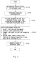
- FIG. 4 is a flowchart showing steps of a method for manufacturing a diffuser plate.
- Fig. 5 is a flowchart showing a designing step of a microlens array according to the first embodiment.
- the method for manufacturing a diffuser plate includes a step (S100) for designing a microlens array that exhibits a desired light diffusion property, a step (S200) for manufacturing a mold of the microlens array, and a step (S300) for transferring a shape of the microlens array to a resin using the mold.
- the step (S100) of designing the microlens array will be explained.
- the specification of the diffuser plate is determined (ST110). Concretely, the specifications such as an optical physical property (in particular, a refractive index), used wavelength, and a required diffusion property of a material used for the diffuser plate are determined.
- a reference microlens is designed from the diffusion properties required for the diffuser plate, and the optical property of the material (ST120).
- the diffusion shape for example, a top hat or Gaussian distribution may be set according to the light distribution properties required for the projection-type image displaying device, and an angle for enlarging the diffusion may further be set.
- the design may be executed based on the assumption that the light is incident substantially vertically on the lens main surface, and the emission light has the same optical axis.
- the reference microlens may be designed by optical line tracking and diffractive calculation, and may be separately used according to the need.
- the reference microlens may be designed by diffractive calculation, and the inclination coping lens can be designed using the optical line tracking. Both of the reference microlens and the inclination coping lens may be designed by the diffractive calculation, or using the optical line tracking.
- the present invention is explained using an optical line tracking method in both of the steps. In this Example, the optical line tracking is analyzed using a lighting design analyzing software LightTools (Registered Trademark).
- the microlens is designed based on a refractive index of the uneven pattern part of the diffuser plate, and the material and the refractive index of the base material film (reference microlens designing step ST120).
- the number of the reference microlens number may be one, and two or more according to the need. In particular, if the strength of diffractive light is higher when the lens size is 100 ⁇ m or less, two or more kinds, a random lens shape, and a shape for modulating a phase may be used.
- the reference microlens designing stage it may be considered that it is assumed that the same reference microlenses are uniformly provided entirely on the main surface of the substrate of the diffuser plate.
- the reference microlens has, for example, a toroidal shape or a biconical surface.
- the inclination of the optical axis of the incident light, the inclination of the optical axis of the emission light, and a required diffusion property are set at each position of the diffuser plate (light setting step ST130).
- an inclination coping lens designing step ST140 based on the designed reference microlens.
- the lens shape is designed at each position of the diffuser plate using the inclination of the optical axis of the incident light, the inclination of the optical axis of the emission light, and the setting of the required diffusion property at each position of the diffuser plate set in the light setting step ST130 as input data.
- the inclination coping lens may be designed by the optical line tracking or the diffractive calculation of all of the respective lenses, and the parameters may be changed by selecting lens parameters to be changed.
- the number of the microlenses might exceed one million, and therefore, a lot of labors are required for individually designing respective lenses.
- the curvature radius, a conical coefficient, a cubic correction coefficient, a lens center position displacement amount, and the lens inclination are selected as parameters of the lens to be designed.
- the inclination is coped by the above-mentioned parameter adjustment, at a portion in which the incident light is incident at a minimum angle, and a portion in which the incident light is incident at a maximum angle, so as to set upper and lower limits of the respective parameters.
- the designing of the respective lenses is omitted using an internal insertion method between them.
- the minimum angle is a minimum value of a crossed angle of the optical axis of the incident light and a virtual axis substantially vertical to the diffuser plate.
- the maximum angle is a maximum value of a crossed angle of the optical axis of the incident light and a virtual axis substantially vertical to the diffuser plate.
- Fig. 6 and Fig. 17 are view for explaining a method for evaluating the evenness of the diffusion property of the emission light.
- a diffusion angle ⁇ s corresponding to a luminance value corresponding to 70% of the optical axis luminance Lo in a region on the left side in Fig. 6 and Fig. 17 , i.e., at an angle smaller than the optical axis diffusion angle ⁇ a, with the optical axis luminance Lo at the optical axis diffusion angle ⁇ a corresponding to the position of the optical axis of the emission light as a reference.
- ⁇ b corresponding to a luminance value corresponding to 70% of the optical axis luminance Lo in a region on the right side in Fig. 6 and Fig.
- the optical axis luminance Lo is designated as a reference, then the optical axis luminance Lo x 0.7 is subtracted from each luminance, and an integrated luminance Ts from the diffusion angle ⁇ s to the optical axis diffusion angle ⁇ a and an integrated luminance Tb from the optical axis diffusion angle ⁇ a to the diffusion angle ⁇ b are calculated.
- an evenness evaluation index Ts/Tb that is a ratio of the integrated luminance Ts and the integrated luminance Tb is calculated, and the evenness of the diffusion property of the emission light is evaluated based on the evenness evaluation index Ts/Tb, and the diffusion range ⁇ s + ⁇ b of the emission light.
- an allowable range D-1/D of the evenness evaluation index Ts/Tb is changed according to the width of the diffusion range ⁇ s + ⁇ b.
- the allowable range D-1/D of the evenness evaluation index is determined according to the diffusion range ⁇ s + ⁇ b as follows.
- the evenness of the diffusion property of the emission light may be determined as sufficient, if a range of the evenness evaluation index Ts/Tb is in a following range, using the lower limit value D and the upper limit value 1/D of the evenness allowable range.
- the evenness evaluation index Ts/Tb exceeds the lower limit value D of the evenness allowable range, 0.90, and the upper limit value 1/D thereof is less than 1.11 because the diffuser plate diffuses the emission light at the even diffusion distribution. It is preferable that, when the diffusion angle ⁇ s + ⁇ b is 20 degrees, the evenness evaluation index Ts/Tb exceeds the lower limit value D of the evenness allowable range, 0.83, and the upper limit value 1/D thereof is less than 1.21 because the diffuser plate diffuses the emission light at the even diffusion distribution.
- the diffusion range ⁇ s + ⁇ b is 10 degrees, and the evenness evaluation index Ts/Tb is 0.99, it is in a range from the lower limit value D, 0.9 to the upper limit value 1/D, 1.11 of the evenness allowable range. That is to say, in the example shown in Fig. 6 , the diffusion property of the emission light is recognized as even.
- the diffusion range ⁇ s + ⁇ b is 10 degrees, and the evenness evaluation index Ts/Tb is about 0.86, and therefore, it is below the lower limit value D of the evenness allowable range, 0.9. That is, in the example shown in Fig. 17 , the diffusion property of the emission light is recognized as uneven.
- the diffusion property of the emission light can be made even regardless of the incident light, so that the corners of the image can be visually recognized clearly, and a high-quality image can be provided.
- a diffuser plate having a function for enlarging an image range can be provided, the device can be made small, and a degree of freedom in designing the image displaying device can be improved.
- a general rotation symmetrical shape may be used as a lens shape of the reference microlens.
- the cross sectional shape of the reference microlens in particular, a sag amount z [ ⁇ m] with a crossing point of the center of the reference microlens and the lens surface as a reference is expressed by the following expression 2.
- C is a curvature [1/ ⁇ m]
- K is a conical coefficient
- r is a distance [ ⁇ m] from the center.
- z ⁇ Cr 2 1 + 1 ⁇ K + 1 C 2 r 2
- the cross sectional shape of the reference microlens used for the diffuser plate in this Example is expressed by the following expression 3.
- the reference microlens is a toroidal lens having a rectangular bottom surface.
- Each position of the reference microlens is defined using an XYZ three-dimensional coordinate.
- the bottom surface is along an XY plane, and a virtual axis substantially vertical to the bottom surface is designated as Z.
- the curvature of a lens convex surface of each reference microlens is defined in an X-direction and a Y-direction.
- a relationship between an X-direction distance r x from an center axis of the reference microlens, a Y-direction distance r y from the center axis of the reference microlens, a curvature C x [1/ ⁇ m] in the X-direction (XZ plane), a curvature C y [1/ ⁇ m] in the Y-direction, a conical coefficient K x in the X-direction (XZ plane), and a conical coefficient K y in the Y-direction (YZ plane) can be expressed by the expression 3.
- the refractive index of a pattern portion of the diffuser plate is 1.52, and the refractive index of a base material is 1.59, using polycarbonate as a base material of the diffuser plate.
- the diffusion shape is rectangle.
- the total diffusion angle of the emission light is 20 degrees
- the vertical direction V for example, a direction along an outer edge of a short side of the diffuser plate 10 shown in Fig. 1
- the total diffusion angle of the emission light is 10 degrees.
- the light distribution shape in each direction is made similar to the shape of a top hat.
- the image from the projection device is incident on a fine uneven surface of the diffuser plate (a pattern surface, in particular, a microlens array, and in more particular, a microlens 2 shown in Fig. 2 ), and emitted as the image light is diffused from a flat surface of a base material surface (for example, a main surface 1b shown in Fig. 2 ).
- the diffuser plate 10 shown in Fig. 1 There is one example of the diffuser plate 10 shown in Fig. 1 .
- This example relates to a rectangular-like plate, and length H L of a long side in the horizontal direction H is 60 mm ( ⁇ 30 mm), and length V L of the long side in the vertical direction V is 30 mm ( ⁇ 15 mm).
- optical line contained in the projection light is vertically incident on a portion corresponding to the origin of this example of the diffuser plate.
- the optical line inclined by ⁇ 5 degrees is incident at both ends in this example of the diffuser plate in the vertical direction V.
- the optical line inclined by ⁇ 10 degrees is incident at both ends in this example of the diffuser plate in the horizontal direction H.
- optical axis angles of the incident light in x, y axial directions at each position of the reference microlens are respectively designated as ⁇ ih (x,y), ⁇ iv (x,y).
- optical axis angles in the emission direction are designated as ⁇ oh (x,y), ⁇ ov (x,y).
- the respective angles are expressed as functions of places.
- the displacements of the optical axis of the emission light from the incident optical axis are respectively designated as D ⁇ oh (x,y), D ⁇ ov (x,y) in the x, y axial directions.
- Various conditions of the reference microlens are set as a horizontal pitch Px30 [ ⁇ m], a curvature radius Rx44.6 [ ⁇ m], a conical coefficient kx-0.75, a vertical pitch Py30 [ ⁇ m], a curvature radius Ry89.3 [ ⁇ m], and a conical coefficient ky-0.75.
- the horizontal pitch Px is a distance between boundaries of the adjacent reference microlenses.
- the vertical pitch Py is a distance between boundaries of the adjacent reference microlenses.
- the displacement amounts of the lens center position are designated as Dh, Dv [ ⁇ m]
- the lens curvature radius coefficients are designated as ⁇ x, ⁇ y
- the cubic function correction coefficients are designated as Ax, Ay.
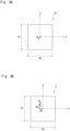
- a center position Ro of the microlens 2 shown in Fig. 9B is displaced by a predetermined distance from a center position Ro of the reference microlens 21 shown in Fig. 9A .
- the center position Ro of the microlens 2 is displaced by a distance Dh in the X-direction and by a distance Dv in the Y-direction, from the center position Ro of the reference microlens 21. That is to say, the displacement amount Dh of the lens center position in the X-direction is a distance in the X-direction from the center position Ro of the reference microlens 21 to the center position Ro of the microlens 2.
- the displacement amount Dv of the lens center position in the Y-direction is a distance in the Y-direction from the center position Ro of the reference microlens 21 to the center position Ro of the microlens 2.
- the optical axis of the diffuser plate is curved only in the vertical direction V, and therefore, the lens may be designed only in the cross section in the vertical direction (V cross section).
- parameters are designed at respective positions V1, V2, V3 on a straight line extending in the vertical direction V.
- an angle of the optical axis of the incident light to the main surface of the lens substrate in the vertical direction V is 0 [deg]
- an angle of the emission optical axis to the main surface of the lens substrate is -2 [deg]
- emission light distribution angle may be in a range of -7 to +3 [deg].
- the displacement amount Dv at the lens center position is -6 [ ⁇ m].
- Fig. 10 shows a cross sectional shape of the microlens at the position V1 in this design.
- Fig. 6 shows the light distribution property in the vertical direction V.
- Fig. 10 indicates an arrow showing a direction in which the projection light L1 and the emission light L2 advance.
- the diffusion range ⁇ s + ⁇ b is 10 degrees, and so, when an evenness evaluation index Ts/Tb is greater than 0.90 that is a lower limit value D of the evenness allowable range and less than 1.11 that is an upper limit value 1/D thereof, the diffusion distribution of the emission light is even.
- the evenness evaluation index Ts/Tb is 0.99, exceeds the lower limit value D of the evenness allowable range, and is less than the upper limit value 1/D thereof, so that the distribution is even.
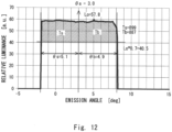
- the angle of the optical axis of the incident light to the main surface of the lens substrate is 5 [deg]
- the emission light distribution angle may be -2 to +8 [deg].
- the cross sectional shape of the microlens at the position V2 in this design is shown in Fig. 11 .
- the light distribution property in the vertical direction V is shown in Fig. 12 .
- the evenness evaluation index Ts/Tb is 1.01, exceeds the lower limit value D of the evenness allowable range, and is less than the upper limit value 1/D thereof, so that the evenness is realized.
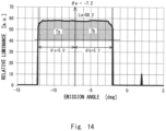
- the angle of the optical axis of the incident light to the main surface of the lens substrate may be -5 [deg]
- the emission light distribution angle may be -12 to -2 [deg].
- the cross sectional shape of the microlens at the position V3 in this design is shown in Fig. 13 .
- the light distribution property in the vertical direction V is shown in Fig. 14 .
- the evenness evaluation index Ts/Tb is 0.98, exceeds the lower limit value D of the evenness allowable range, and is less than the upper limit value 1/D thereof, so that the evenness is realized.
- each parameter, a cubic function correction amount Ay, and a lens curvature radius coefficient ⁇ y at each position of the Y-coordinate are expressed by the following expression.
- the optical axis of the emission light can be curved to the optical axis of the incident light by -2 [deg] in the vertical direction V, and by -3 [deg] in the horizontal direction H, at the same time. In this manner, a design that the optical axis of the emission light is curved in a two-dimensional direction can be executed.
- Example 1 a constant change of the optical axis of the emission light is given to the optical axis of the incident light.
- Example 4 in a range from an Y-coordinate position, -15 mm to +15 mm in the diffuser plate surface in the vertical direction V, under a condition that the incident angle ⁇ iv of the incident light varies from -5 deg to +5 deg, the optical axis of the emission light is changed by the emission angle D ⁇ ov [deg] in the Y-direction to the optical axis of the incident light at each Y position. That is to say, the optical axis is continuously varied along the Y-direction.
- a target property can be obtained by the following parameter in executing the design at three points of the diffuser plate according to Example 4.
- the displacement amount Dv of the lens center, and the cubic function correction amount Ay are set so that they are expressed by the following expression.
- Dv ⁇ 6.0 * Y/15
- E ⁇ 06 * Y/15 ⁇ x 1 + 0.02 ⁇ Y/15
- a diffuser plate having a reference microlens with the same configuration as that of the reference microlens of the microlens array of the diffuser plate used in Example 1 is used.
- Fig. 17 shows a light distribution property when the light inclined to 5 degrees is incident on the diffuser plate.
- the optical axis ⁇ a of the emission light is 5 deg
- the diffusion range ⁇ s + ⁇ b is 10 deg
- the allowable range D-1/D of the evenness evaluation index Ts/Tb is greater than 0.90 and less than 1.11.
- the evenness evaluation index Ts/Tb is 0.86 and is not included in the allowable range D-1/D, and therefore, it is determined that the evenness is not sufficient.
- the optical axis when the light is diagonally incident, the optical axis is almost the same as that of the incident light, and the light distribution is inclined, so as to cause uneven luminance.
- a diffuser plate having an inclination lens formed by inclining the reference microlens itself with the same configuration as the reference microlens of the microlens array of the diffuser plate used in Example 1 by 10 degrees is used.
- the inclination lens has the same shape as the shape inclined by 10 degrees by simply changing the reference lens shape by y*tan (10 deg).
- Fig. 15 shows the light distribution property at that time.
- the diffusion range ⁇ s + ⁇ b is 9.7 deg
- the allowable range D-1/D of the evenness evaluation index Ts/Tb is greater than 0.90 and less than 1.11.
- the evenness evaluation index Ts/Tb is 0.87, and is not included in the allowable range D-1/D, and therefore, it is determined that the evenness is not sufficient.
- the optical axis of the emission light can be curved, however, the light distribution of the emission light is inclined, so as to cause uneven luminance.
- the diffuser plate 10 is a transmissive diffuser plate, and may be a reflective diffuser plate.
- the reflective diffuser plate comprises a main surface to which the projection light is projected and that reflects the reflection light, and a fine structure having a mirror function on the main surface.
- the fine structure whose numerical aperture NA of the projection light is greater than 0 and 0.140 or less comprises a plurality of microlens shaped mirror parts having a microlens-like shape.
- An incident angle ⁇ i formed by the optical axis of the projection light at the microlens shaped mirror part and a normal of the main surface intersecting with each other is in a range of 0-50 degrees.
- At least one of the plurality of microlens shaped mirror parts reflects the reflection light at a reflection angle formed by the optical axis of the reflection light at the microlens shaped mirror part and the normal of the main surface intersecting with each other.
- the reflection light is different from the incident angle ⁇ i.
- the reflection light has substantially even luminance in the range of a desired diffusion angle.
- the cross sectional shape of the microlens shaped mirror part has an asymmetrical cross sectional shape around the optical axis of the projection light.
- the incident angle ⁇ i formed by the optical axis of the projection light at the microlens shaped mirror part and the normal of the main surface intersecting with each other is greater than 0 degrees and 50 degrees or less, and the reflection light may be the same as the incident angle ⁇ i.
- microlens shaped mirror part may be designed using the above-mentioned method for designing the diffuser plate 10.
Landscapes
- Physics & Mathematics (AREA)
- General Physics & Mathematics (AREA)
- Optics & Photonics (AREA)
- Engineering & Computer Science (AREA)
- Chemical & Material Sciences (AREA)
- Combustion & Propulsion (AREA)
- Transportation (AREA)
- Mechanical Engineering (AREA)
- Manufacturing & Machinery (AREA)
- Optical Elements Other Than Lenses (AREA)
- Overhead Projectors And Projection Screens (AREA)
- Projection Apparatus (AREA)
Claims (8)
- Eine Projektionsbild-Anzeigevorrichtung, die Folgendes umfasst:eine Diffusorplatte (10); undeine Projektionsvorrichtung (20) zum Projizieren des Projektionslichts (L1) auf die Diffusorplatte (10),wobei die Diffusorplatte (10) Folgendes umfasst:eine projektionsseitige Hauptfläche (1a), auf die Projektionslicht (L1) projiziert wird;eine emissionsseitige Hauptoberfläche (1b) zum Emittieren von Emissionslicht (L2); undeine Feinstruktur mit einer Linsenfunktion auf mindestens einer von der projektionsseitigen Hauptfläche (1a) und der emissionsseitigen Hauptfläche (1b), wobeidie Feinstruktur eine Vielzahl von Mikrolinsen-Formteilen (2) mit einer mikrolinsenartigen Form aufweist,mindestens eines von der Vielzahl von Mikrolinsen-Formteilen (2) das Emissionslicht (L2) unter einem Emissionswinkel (θo) emittiert, der dadurch gebildet wird, dass die optische Achse des Emissionslichts (L2) am Mikrolinsen-Formteil (2) und die Normale der projektionsseitigen Hauptoberfläche (1a) einander schneiden,das Emissionslicht (L2) in einem gewünschten Streu- bzw. Diffusionswinkelbereich (diffusion angle range) eine im Wesentlichen gleichmäßige Leuchtdichte aufweist, und eine Querschnittsform des Mikrolinsen-Formteils (2) in einem Querschnitt im Wesentlichen senkrecht zu einer Mikrolinsen-Referenzfläche des Mikrolinsen-Formteils (2) eine asymmetrische Querschnittsform um die optische Achse des Projektionslichts (L1) aufweist, wobeiin der Messleuchtdichteverteilung zum Diffusionswinkel (θb, θs),wenn der Diffusionswinkel (θb, θs), der der Position der optischen Achse des Emissionslichts (L2) entspricht, als ein Diffusionswinkel (θa) der optischen Achse bezeichnet wird,ein integrierter Wert (To) der Messleuchtdichte von einem minimalen Winkel (θmin) in einem vorbestimmten Bereich des Diffusionswinkels (θb, θs) bis zum Diffusionswinkel (θa) der optischen Achse 50 % eines integrierten Wertes (Ta) der Messleuchtdichte im gesamten Bereich des Diffusionswinkels (θb, θs) beträgt,ein Absolutwert einer Differenz eines Winkels, der dadurch gebildet wird, dass die optische Achse des Projektionslichts (L1) und die optische Achse des Emissionslichts (L2) einander schneiden, innerhalb von 0-40 Grad variiert, die Leuchtdichte (Ls) bei einem vorbestimmten Diffusionswinkel (θs) bzw. die Leuchtdichte (Lb) bei einem vorbestimmten Diffusionswinkel (θb) 70 % der Optischen-Achsen-Leuchtdichte (Lo) an der optischen Achse des Emissionslichts (L2) entspricht,wenn der vorbestimmte Diffusionswinkel (θs) kleiner ist als der Diffusionswinkel (θa) der optischen Achse, und der vorbestimmte Diffusionswinkel (θb) größer ist als der Diffusionswinkel (θa) der optischen Achse,ein Ebenheit-Bewertungsindex (Ts/Tb), der ein Verhältnis eines integrierten Werts (Ts) der Leuchtdichte, der durch Subtrahieren von Lo*0,7 von jeder Leuchtdichte vom Diffusionswinkel (θs) zum Diffusionswinkel der optischen Achse (θa) erhalten wird, und eines integrierten Werts (Tb) der Leuchtdichte vom Diffusionswinkel der optischen Achse (θa) zum vorbestimmten Diffusionswinkel (θb) ist, D < Ts/Tb < 1/D erfüllt, undein unterer Grenzwert (D) des zulässigen Bereichs des Ebenheit-Bewertungsindex (Ts/Tb) D = 0,63*exp(0,45*((90-(θs + θb))/90)^2) erfüllt,die Projektionsvorrichtung (20) dazu ausgelegt ist, Projektionslicht (L1) mit einer numerischen Apertur (NA) zwischen 0 und 0,140 zu emittieren, wobei entweder:(a) ein Einfallswinkel (θi), der dadurch gebildet wird, dass eine optische Achse des Projektionslichts (L1) am Mikrolinsen-Formteil (2) und eine Normale der projektionsseitigen Hauptoberfläche (1a) einander schneiden, in einem Bereich von 0 bis 50 Grad liegt, und der Emissionswinkel (θo) vom Einfallswinkel (θi) verschieden ist, oder(b) ein Einfallswinkel (θi), der dadurch gebildet wird, dass eine optische Achse des Projektionslichts (L1) am Mikrolinsen-Formteil (2) und eine Normale der projektionsseitigen Hauptoberfläche (1a) einander schneiden, größer ist als 0 Grad und 50 Grad oder weniger, und der Emissionswinkel (θo) dem Einfallswinkel (θi) gleicht, undwobeidie Form der Bodenfläche des Mikrolinsen-Formteils (2) rechteckig ist, unddie Mikrolinsen-Formteile (2) periodisch gitterförmig angeordnet sind,wobei die Höhe (H1) [µm] vom tiefsten Teil bis zum obersten Teil des Mikrolinsen-Formteils (2) Folgendes erfüllt: 0 < H1 ≤ 75.
- Ein Verfahren zum Entwerfen einer Diffusorplatte (10), um ein Lichtdiffusionsmuster der Diffusorplatte (10) zu entwerfen, die Folgendes beinhaltet: eine projektionsseitige Hauptoberfläche (1a), auf die Projektionslicht (L1) projiziert wird, eine emissionsseitige Hauptoberfläche (1b) zum Emittieren von Emissionslicht (L2) und eine Feinstruktur mit einer Linsenfunktion auf mindestens einer von der projektionsseitigen Hauptoberfläche (1a) und der emissionsseitigen Hauptoberfläche (1b), wobei die Feinstruktur eine Vielzahl von Mikrolinsen-Formteilen (2) mit einer mikrolinsenartigen Form aufweist,
wobeidie Form der Bodenfläche des Mikrolinsen-Formteils (2) rechteckig ist unddie Mikrolinsen-Formteile (2) periodisch gitterförmig angeordnet sind,wobei die Höhe (H1) [µm] vom tiefsten Teil zum obersten Teil des Mikrolinsen-Formteils (2) Folgendes erfüllt: 0 < H1 ≤ 75,wobei das Verfahren Folgendes beinhaltet:einen Referenzmikrolinsen-Entwurfsschritt, um eine Referenzmikrolinse so vorzubereiten, dass eine gewünschte Lichtstreuungs- bzw. Lichtdiffusions-Eigenschaft erreicht wird, wenn angenommen wird, dass Licht vertikal auf die projektionsseitige Hauptfläche (1a) der Diffusorplatte (10) projiziert wird, undeinen Neigungsanpassungs- (inclination coping) Linsen-Entwurfsschritt, für das Anpassen an die Neigung der optischen Achse des Projektionslichts (L1) und die Neigung der optischen Achse des Emissionslichts (L2) der Form der Referenzmikrolinse, auf der Grundlage der Neigung der optischen Achse des Projektionslichts (L1) an jeder Position der projektionsseitigen Hauptoberfläche (1a) der Diffusorplatte (10), der Neigung der optischen Achse des Projektionslichts (L1) an jeder Position der projektionsseitigen Hauptoberfläche (1a) der Diffusorplatte (10) und einer Lichtverteilungseigenschaft des Emissionslichts (L2), wobeiim Neigungsanpassungs-Linsen-Entwurfsschritt die Linsenentwurfsparameter einen Verschiebungsbetrag der Mittenposition (Ro) zum Verschieben einer Mittenposition (Ro) der Linse beinhalten, und umfassend den Schritt desquantitatives Auswerten der Ebenheit der Diffusionseigenschaften des Emissionslichts, was Folgendes beinhaltet:in der Messleuchtdichteverteilung zum Diffusionswinkel (θb, θs),wenn der Diffusionswinkel (θb, θs), der der Position der optischen Achse des Emissionslichts (L2) entspricht, als ein Diffusionswinkel (θa) der optischen Achse bezeichnet wird,beträgt ein integrierter Wert (To) der Messleuchtdichte von einem minimalen Winkel (θmin) in einem vorbestimmten Bereich des Diffusionswinkels (θb, θs) bis zum Diffusionswinkel (θa) der optischen Achse 50% eines integrierten Wertes (Ta) der Messleuchtdichte im gesamten Bereich des Diffusionswinkels (θb, θs),variiert ein absoluter Wert einer Differenz eines Winkels, der dadurch gebildet wird, dass die optische Achse des Projektionslichts (L1) und die optische Achse des Emissionslichts (L2) einander schneiden innerhalb von 0-40 Grad, entsprechen die Leuchtdichte (Ls) bei einem vorbestimmten Diffusionswinkel (θs) und die Leuchtdichte (Lb) bei einem vorbestimmten Diffusionswinkel (θb) jeweils 70% der Optischen-Achsen-Leuchtdichte (Lo) bei der optischen Achse des Emissionslichts (L2),wenn der vorbestimmte Diffusionswinkel (θs) kleiner ist als der Diffusionswinkel (θa) der optischen Achse, und der vorbestimmte Diffusionswinkel (θb) größer ist als der Diffusionswinkel (θa) der optischen Achse,Berechnen eines Ebenheits-Bewertungsindex (Ts/Tb), der ein Verhältnis eines integrierten Wertes (Ts) der Leuchtdichte, der durch Subtrahieren von Lo*0,7 von jeder Leuchtdichte aus dem Diffusionswinkel (θs) zum Diffusionswinkel (θa) der optischen Achse erhalten wird, und eines integrierten Wertes (Tb) der Leuchtdichte aus dem Diffusionswinkel (θa) der optischen Achse ist, und Bestimmen, ob der vorbestimmte Diffusionswinkel (θb) D < Ts/Tb < 1/D erfüllt, wobeiein unterer Grenzwert (D) des zulässigen Bereichs des Ebenheit-Bewertungsindex (Ts/Tb) D = 0,63*exp(0,45*((90-(θs + θb))/90)^2) erfüllt. - Das Verfahren zum Entwerfen einer Diffusorplatte (10) nach Anspruch 2, wobei im Neigungsanpassungs-Linsen-Entwurfsschritt die Linsenentwurfsparameter ferner einen Linsenneigungsbetrag beinhalten.
- Das Verfahren zum Entwerfen einer Diffusorplatte (10) nach Anspruch 2 oder 3, wobei im Neigungsanpassungs-Linsen-Entwurfsschritt die Linsenentwurfsparameter ferner einen Linsenkrümmungsradius-Änderungsbetrag zum Vergrößern oder Verringern eines Linsenkrümmungsradius' beinhalten.
- Das Verfahren zum Entwerfen einer Diffusorplatte (10) nach irgendeinem der Ansprüche von 2 bis 4, wobei im Neigungsanpassungs-Linsen-Entwurfsschritt die Linsenentwurfsparameter ferner einen Einstellungsbetrag zum Einstellen einer Linsenform durch eine kubische Funktion oder eine ähnliche Funktion beinhalten.
- Das Verfahren zum Entwerfen einer Diffusorplatte (10) nach irgendeinem der Ansprüche von 2 bis 5, wobeidie Referenzmikrolinse eine Linsenform zur jeweiligen Steuerung von zwei Querschnittsformen in zwei verschiedenen Querschnitten aufweist, einschließlich einer Normalenrichtung der projektionsseitigen Hauptfläche (1a) oder der emissionsseitigen Hauptfläche (1b), undEntwerfen einer Linse für die zwei Querschnittsformen der Referenzmikrolinse.
- Das Verfahren zum Entwerfen einer Diffusorplatte (10) nach Anspruch 6, wobei die Referenzmikrolinse eine toroidale Form aufweist.
- Eine Projektionsbild-Anzeigevorrichtung, die Folgendes umfasst:eine Diffusorplatte (10); undeine Projektionsvorrichtung (20) zum Projizieren des Projektionslichts (L1) auf die Diffusorplatte (10),wobei die Diffusorplatte (10) Folgendes umfasst:eine Hauptoberfläche, auf die Projektionslicht (L1) projiziert wird und von der Reflexionslicht reflektiert wird; undeine Feinstruktur mit einer Spiegelfunktion auf der Hauptoberfläche, wobeidie Feinstruktur eine Vielzahl von mikrolinsenförmigen Spiegelteilen mit einer mikrolinsenartigen Form aufweist,mindestens eines von der Vielzahl von mikrolinsenförmigen Spiegelteilen das Reflexionslicht unter einem Reflexionswinkel reflektiert, der dadurch gebildet wird, dass die optische Achse des Reflexionslichts am mikrolinsenförmigen Spiegelteil und die Normale der Hauptoberfläche einander schneiden,das Reflexionslicht eine im Wesentlichen gleichmäßige Leuchtdichte in einem gewünschten Streuwinkel- bzw. Diffusionswinkel-Bereich aufweist und wobeieine Querschnittsform des mikrolinsenförmigen Spiegelteils in einem Querschnitt im Wesentlichen senkrecht zu einer Mikrolinsen-Referenzfläche des mikrolinsenförmigen Spiegelteils eine asymmetrische Querschnittsform um die optische Achse des Projektionslichts (L1) aufweist, wobeiin der Messleuchtdichteverteilung zum Diffusionswinkel (θb, θs),wenn der Diffusionswinkel (θb, θs), der der Position der optischen Achse des Emissionslichts (L2) entspricht, als ein Diffusionswinkel (θa) der optischen Achse bezeichnet wird,ein integrierter Wert (To) der Messleuchtdichte von einem minimalen Winkel (θmin) in einem vorbestimmten Bereich des Diffusionswinkels (θb, θs) bis zum Diffusionswinkel (θa) der optischen Achse 50 % eines integrierten Wertes (Ta) der Messleuchtdichte im gesamten Bereich des Diffusionswinkels (θb, θs) beträgt,ein Absolutwert einer Differenz eines Winkels, der dadurch gebildet wird, dass die optische Achse des Projektionslichts (L1) und die optische Achse des Emissionslichts (L2) einander schneiden, innerhalb von 0-40 Grad variiert, die Leuchtdichte (Ls) bei einem vorbestimmten Diffusionswinkel (θs) bzw. die Leuchtdichte (Lb) bei einem vorbestimmten Diffusionswinkel (θb) 70 % der Optischen-Achsen-Leuchtdichte (Lo) an der optischen Achse des Emissionslichts (L2) entspricht,wenn der vorbestimmte Diffusionswinkel (θs) kleiner ist als der Diffusionswinkel (θa) der optischen Achse, und der vorbestimmte Diffusionswinkel (θb) größer ist als der Diffusionswinkel (θa) der optischen Achse,ein Ebenheit-Bewertungsindex (Ts/Tb), der ein Verhältnis eines integrierten Werts (Ts) der Leuchtdichte, der durch Subtrahieren von Lo*0,7 von jeder Leuchtdichte vom Diffusionswinkel (θs) zum Diffusionswinkel der optischen Achse (θa) erhalten wird, und eines integrierten Werts (Tb) der Leuchtdichte vom Diffusionswinkel der optischen Achse (θa) zum vorbestimmten Diffusionswinkel (θb) ist, D < Ts/Tb < 1/D erfüllt, undein unterer Grenzwert (D) des zulässigen Bereichs des Ebenheit-Bewertungsindex (Ts/Tb) D = 0,63*exp(0,45*((90-(θs + θb))/90)^2) erfüllt,die Projektionsvorrichtung (20) dazu ausgelegt ist, Projektionslicht (L1) mit einer numerischen Apertur (NA) zwischen 0 und 0,140 zu emittieren, wobei entweder:(a) ein Einfallswinkel (θi), der dadurch gebildet wird, dass eine optische Achse des Projektionslichts (L1) am mikrolinsenförmigen Spiegelteil und eine Normale der Hauptoberfläche einander schneiden, in einem Bereich von 0 bis 50 Grad liegt, und das Reflexionslicht vom Einfallswinkel (θi) verschieden ist, oder(b) ein Einfallswinkel (θi), der dadurch gebildet wird, dass eine optische Achse des Projektionslichts (L1) am mikrolinsenförmigen Spiegelteil und eine Normale der Hauptoberfläche sich schneiden, größer ist als 0 Grad und 50 Grad oder weniger, und das Reflexionslicht dem Einfallswinkel (θi) gleicht, undwobeidie Form der Bodenfläche des Mikrolinsen-Formteils (2) rechteckig ist, unddie Mikrolinsen-Formteile (2) periodisch gitterförmig angeordnet sind,wobei die Höhe (H1) [µm] vom tiefsten Teil zum obersten Teil des Mikrolinsen-Formteils (2) Folgendes erfüllt: 0 < H1 ≤ 75.
Applications Claiming Priority (2)
| Application Number | Priority Date | Filing Date | Title |
|---|---|---|---|
| JP2016195461 | 2016-10-03 | ||
| PCT/JP2017/035802 WO2018066501A1 (ja) | 2016-10-03 | 2017-10-02 | 拡散板及び投写式画像表示装置 |
Publications (3)
| Publication Number | Publication Date |
|---|---|
| EP3521873A1 EP3521873A1 (de) | 2019-08-07 |
| EP3521873A4 EP3521873A4 (de) | 2020-04-22 |
| EP3521873B1 true EP3521873B1 (de) | 2024-09-25 |
Family
ID=61831575
Family Applications (1)
| Application Number | Title | Priority Date | Filing Date |
|---|---|---|---|
| EP17858339.9A Active EP3521873B1 (de) | 2016-10-03 | 2017-10-02 | Diffusionsplatte und bildanzeigevorrichtung vom projektionstyp |
Country Status (6)
| Country | Link |
|---|---|
| US (1) | US11175440B2 (de) |
| EP (1) | EP3521873B1 (de) |
| JP (1) | JP7109367B2 (de) |
| KR (1) | KR102266524B1 (de) |
| CN (1) | CN109791232B (de) |
| WO (1) | WO2018066501A1 (de) |
Families Citing this family (9)
| Publication number | Priority date | Publication date | Assignee | Title |
|---|---|---|---|---|
| DE112019002950T5 (de) * | 2018-07-11 | 2021-04-08 | Nippon Seiki Co. Ltd. | Anzeigevorrichtung und Head-up-Display-Vorrichtung |
| JP7087828B2 (ja) * | 2018-08-27 | 2022-06-21 | セイコーエプソン株式会社 | 光学素子、光射出装置および画像表示システム |
| KR102129703B1 (ko) * | 2020-02-06 | 2020-07-03 | 주식회사 옵토전자 | 회절 방식을 이용한 마이크로 광학소자 시스템 |
| CN111221062B (zh) * | 2020-03-19 | 2022-02-08 | 宁波舜宇车载光学技术有限公司 | 显示设备 |
| CN111239869B (zh) * | 2020-03-19 | 2022-02-22 | 宁波舜宇车载光学技术有限公司 | 扩散板 |
| TW202204969A (zh) | 2020-05-27 | 2022-02-01 | 日商索尼集團公司 | 圖像顯示裝置及投射光學系統 |
| JP7779854B2 (ja) * | 2020-11-17 | 2025-12-03 | 株式会社クラレ | マイクロアレイ型拡散板 |
| CN114690520B (zh) * | 2020-12-29 | 2024-04-12 | 宁波舜宇车载光学技术有限公司 | 一种发射端及其制备方法 |
| JPWO2024214757A1 (de) * | 2023-04-14 | 2024-10-17 |
Family Cites Families (14)
| Publication number | Priority date | Publication date | Assignee | Title |
|---|---|---|---|---|
| US6498685B1 (en) * | 1999-01-11 | 2002-12-24 | Kenneth C. Johnson | Maskless, microlens EUV lithography system |
| EP1305656A4 (de) | 2000-07-31 | 2006-03-08 | Rochester Photonics Corp | Strukturierte schirme für regulierte diffusion von licht |
| US6859326B2 (en) | 2002-09-20 | 2005-02-22 | Corning Incorporated | Random microlens array for optical beam shaping and homogenization |
| JP4089371B2 (ja) * | 2002-09-24 | 2008-05-28 | セイコーエプソン株式会社 | 透過型スクリーン及びリア型プロジェクタ |
| JP2005070631A (ja) * | 2003-08-27 | 2005-03-17 | Seiko Epson Corp | スクリーン及びプロジェクタ |
| JP4238782B2 (ja) * | 2004-06-08 | 2009-03-18 | ソニー株式会社 | 光拡散フィルム及びその製造方法、並びにスクリーン |
| JP5087765B2 (ja) * | 2006-01-10 | 2012-12-05 | 国立大学法人東北大学 | 投写システム |
| JP2010145745A (ja) | 2008-12-18 | 2010-07-01 | Equos Research Co Ltd | 画像形成装置、及び、ヘッドアップディスプレイ装置 |
| JP5344069B2 (ja) * | 2011-08-29 | 2013-11-20 | 株式会社デンソー | ヘッドアップディスプレイ装置 |
| JP2014149405A (ja) | 2013-01-31 | 2014-08-21 | Nippon Seiki Co Ltd | ヘッドアップディスプレイ装置 |
| JP6260345B2 (ja) * | 2014-01-06 | 2018-01-17 | 株式会社Jvcケンウッド | 中間像形成部及びそれを用いた画像表示装置 |
| JP2015169804A (ja) | 2014-03-07 | 2015-09-28 | 株式会社リコー | レンズアレイ、画像表示装置、及び移動体 |
| WO2016051766A1 (ja) | 2014-09-30 | 2016-04-07 | 株式会社クラレ | 拡散板及び拡散板の製造方法 |
| KR101945661B1 (ko) | 2015-03-12 | 2019-02-07 | 주식회사 쿠라레 | 확산판 |
-
2017
- 2017-10-02 WO PCT/JP2017/035802 patent/WO2018066501A1/ja not_active Ceased
- 2017-10-02 US US16/338,849 patent/US11175440B2/en active Active
- 2017-10-02 CN CN201780061015.0A patent/CN109791232B/zh active Active
- 2017-10-02 KR KR1020197009286A patent/KR102266524B1/ko active Active
- 2017-10-02 EP EP17858339.9A patent/EP3521873B1/de active Active
- 2017-10-02 JP JP2018543884A patent/JP7109367B2/ja active Active
Also Published As
| Publication number | Publication date |
|---|---|
| KR102266524B1 (ko) | 2021-06-17 |
| CN109791232B (zh) | 2022-04-26 |
| EP3521873A4 (de) | 2020-04-22 |
| WO2018066501A1 (ja) | 2018-04-12 |
| JP7109367B2 (ja) | 2022-07-29 |
| CN109791232A (zh) | 2019-05-21 |
| EP3521873A1 (de) | 2019-08-07 |
| KR20190039833A (ko) | 2019-04-15 |
| JPWO2018066501A1 (ja) | 2019-07-18 |
| US11175440B2 (en) | 2021-11-16 |
| US20200284952A1 (en) | 2020-09-10 |
Similar Documents
| Publication | Publication Date | Title |
|---|---|---|
| EP3521873B1 (de) | Diffusionsplatte und bildanzeigevorrichtung vom projektionstyp | |
| US20200310135A1 (en) | Multibeam element-based near-eye display, system, and method | |
| CN104345458B (zh) | 平视显示设备 | |
| KR102762044B1 (ko) | 정적-이미지 증강 사생활보호 디스플레이, 모드-전환가능 사생활보호 디스플레이 시스템, 및 방법 | |
| US10191287B2 (en) | Optical element and display device | |
| EP3255492B1 (de) | Lichtdurchlässiger schirm und frontsichtanzeigevorrichtung damit | |
| US11372250B2 (en) | Head-mounted display having reflective elements | |
| US7075718B2 (en) | Transparent screen and projection display apparatus | |
| US20190391313A1 (en) | Image display device | |
| US20230011557A1 (en) | Display device | |
| US10466393B2 (en) | Display device | |
| CN112882240B (zh) | 显示装置以及显示方法 | |
| JPH11338056A (ja) | 映像表示装置 | |
| US20220392136A1 (en) | Animated static multiview display and method | |
| US10852539B2 (en) | Projection optical system, head-up display device, and vehicle | |
| JP2021189370A (ja) | 投射光学系および照明装置 | |
| CN113640903A (zh) | 复眼透镜、背光照明系统及其制造方法 | |
| JP6904398B2 (ja) | 光学システム、画像表示装置及び物体装置 | |
| CN110780514B (zh) | 透镜和投射型图像显示装置 | |
| JP7357233B2 (ja) | ヘッドアップディスプレイ | |
| JP6658797B2 (ja) | ヘッドアップディスプレイ用光学素子 |
Legal Events
| Date | Code | Title | Description |
|---|---|---|---|
| STAA | Information on the status of an ep patent application or granted ep patent |
Free format text: STATUS: THE INTERNATIONAL PUBLICATION HAS BEEN MADE |
|
| PUAI | Public reference made under article 153(3) epc to a published international application that has entered the european phase |
Free format text: ORIGINAL CODE: 0009012 |
|
| STAA | Information on the status of an ep patent application or granted ep patent |
Free format text: STATUS: REQUEST FOR EXAMINATION WAS MADE |
|
| 17P | Request for examination filed |
Effective date: 20190411 |
|
| AK | Designated contracting states |
Kind code of ref document: A1 Designated state(s): AL AT BE BG CH CY CZ DE DK EE ES FI FR GB GR HR HU IE IS IT LI LT LU LV MC MK MT NL NO PL PT RO RS SE SI SK SM TR |
|
| AX | Request for extension of the european patent |
Extension state: BA ME |
|
| DAV | Request for validation of the european patent (deleted) | ||
| DAX | Request for extension of the european patent (deleted) | ||
| A4 | Supplementary search report drawn up and despatched |
Effective date: 20200324 |
|
| RIC1 | Information provided on ipc code assigned before grant |
Ipc: G03B 21/62 20140101ALI20200318BHEP Ipc: G02B 5/09 20060101ALI20200318BHEP Ipc: G02B 3/00 20060101ALI20200318BHEP Ipc: B60K 35/00 20060101ALI20200318BHEP Ipc: G02B 5/02 20060101AFI20200318BHEP Ipc: G02B 27/01 20060101ALI20200318BHEP |
|
| STAA | Information on the status of an ep patent application or granted ep patent |
Free format text: STATUS: EXAMINATION IS IN PROGRESS |
|
| 17Q | First examination report despatched |
Effective date: 20210303 |
|
| P01 | Opt-out of the competence of the unified patent court (upc) registered |
Effective date: 20230517 |
|
| GRAP | Despatch of communication of intention to grant a patent |
Free format text: ORIGINAL CODE: EPIDOSNIGR1 |
|
| STAA | Information on the status of an ep patent application or granted ep patent |
Free format text: STATUS: GRANT OF PATENT IS INTENDED |
|
| RIC1 | Information provided on ipc code assigned before grant |
Ipc: G02B 5/09 20060101ALI20240415BHEP Ipc: G03B 21/62 20140101ALI20240415BHEP Ipc: G02B 27/01 20060101ALI20240415BHEP Ipc: G02B 3/00 20060101ALI20240415BHEP Ipc: B60K 35/00 20060101ALI20240415BHEP Ipc: G03B 21/625 20140101ALI20240415BHEP Ipc: G02B 17/00 20060101ALI20240415BHEP Ipc: G02B 5/02 20060101AFI20240415BHEP |
|
| INTG | Intention to grant announced |
Effective date: 20240430 |
|
| GRAS | Grant fee paid |
Free format text: ORIGINAL CODE: EPIDOSNIGR3 |
|
| GRAA | (expected) grant |
Free format text: ORIGINAL CODE: 0009210 |
|
| STAA | Information on the status of an ep patent application or granted ep patent |
Free format text: STATUS: THE PATENT HAS BEEN GRANTED |
|
| AK | Designated contracting states |
Kind code of ref document: B1 Designated state(s): AL AT BE BG CH CY CZ DE DK EE ES FI FR GB GR HR HU IE IS IT LI LT LU LV MC MK MT NL NO PL PT RO RS SE SI SK SM TR |
|
| REG | Reference to a national code |
Ref country code: GB Ref legal event code: FG4D |
|
| REG | Reference to a national code |
Ref country code: CH Ref legal event code: EP |
|
| REG | Reference to a national code |
Ref country code: DE Ref legal event code: R096 Ref document number: 602017085125 Country of ref document: DE |
|
| REG | Reference to a national code |
Ref country code: IE Ref legal event code: FG4D |
|
| REG | Reference to a national code |
Ref country code: LT Ref legal event code: MG9D |
|
| PG25 | Lapsed in a contracting state [announced via postgrant information from national office to epo] |
Ref country code: NO Free format text: LAPSE BECAUSE OF FAILURE TO SUBMIT A TRANSLATION OF THE DESCRIPTION OR TO PAY THE FEE WITHIN THE PRESCRIBED TIME-LIMIT Effective date: 20241225 |
|
| PG25 | Lapsed in a contracting state [announced via postgrant information from national office to epo] |
Ref country code: GR Free format text: LAPSE BECAUSE OF FAILURE TO SUBMIT A TRANSLATION OF THE DESCRIPTION OR TO PAY THE FEE WITHIN THE PRESCRIBED TIME-LIMIT Effective date: 20241226 Ref country code: FI Free format text: LAPSE BECAUSE OF FAILURE TO SUBMIT A TRANSLATION OF THE DESCRIPTION OR TO PAY THE FEE WITHIN THE PRESCRIBED TIME-LIMIT Effective date: 20240925 |
|
| PG25 | Lapsed in a contracting state [announced via postgrant information from national office to epo] |
Ref country code: BG Free format text: LAPSE BECAUSE OF FAILURE TO SUBMIT A TRANSLATION OF THE DESCRIPTION OR TO PAY THE FEE WITHIN THE PRESCRIBED TIME-LIMIT Effective date: 20240925 |
|
| PG25 | Lapsed in a contracting state [announced via postgrant information from national office to epo] |
Ref country code: LV Free format text: LAPSE BECAUSE OF FAILURE TO SUBMIT A TRANSLATION OF THE DESCRIPTION OR TO PAY THE FEE WITHIN THE PRESCRIBED TIME-LIMIT Effective date: 20240925 |
|
| PG25 | Lapsed in a contracting state [announced via postgrant information from national office to epo] |
Ref country code: RS Free format text: LAPSE BECAUSE OF FAILURE TO SUBMIT A TRANSLATION OF THE DESCRIPTION OR TO PAY THE FEE WITHIN THE PRESCRIBED TIME-LIMIT Effective date: 20241225 |
|
| REG | Reference to a national code |
Ref country code: NL Ref legal event code: MP Effective date: 20240925 |
|
| PG25 | Lapsed in a contracting state [announced via postgrant information from national office to epo] |
Ref country code: RS Free format text: LAPSE BECAUSE OF FAILURE TO SUBMIT A TRANSLATION OF THE DESCRIPTION OR TO PAY THE FEE WITHIN THE PRESCRIBED TIME-LIMIT Effective date: 20241225 Ref country code: NO Free format text: LAPSE BECAUSE OF FAILURE TO SUBMIT A TRANSLATION OF THE DESCRIPTION OR TO PAY THE FEE WITHIN THE PRESCRIBED TIME-LIMIT Effective date: 20241225 Ref country code: LV Free format text: LAPSE BECAUSE OF FAILURE TO SUBMIT A TRANSLATION OF THE DESCRIPTION OR TO PAY THE FEE WITHIN THE PRESCRIBED TIME-LIMIT Effective date: 20240925 Ref country code: GR Free format text: LAPSE BECAUSE OF FAILURE TO SUBMIT A TRANSLATION OF THE DESCRIPTION OR TO PAY THE FEE WITHIN THE PRESCRIBED TIME-LIMIT Effective date: 20241226 Ref country code: FI Free format text: LAPSE BECAUSE OF FAILURE TO SUBMIT A TRANSLATION OF THE DESCRIPTION OR TO PAY THE FEE WITHIN THE PRESCRIBED TIME-LIMIT Effective date: 20240925 Ref country code: BG Free format text: LAPSE BECAUSE OF FAILURE TO SUBMIT A TRANSLATION OF THE DESCRIPTION OR TO PAY THE FEE WITHIN THE PRESCRIBED TIME-LIMIT Effective date: 20240925 |
|
| REG | Reference to a national code |
Ref country code: AT Ref legal event code: MK05 Ref document number: 1727105 Country of ref document: AT Kind code of ref document: T Effective date: 20240925 |
|
| PG25 | Lapsed in a contracting state [announced via postgrant information from national office to epo] |
Ref country code: NL Free format text: LAPSE BECAUSE OF FAILURE TO SUBMIT A TRANSLATION OF THE DESCRIPTION OR TO PAY THE FEE WITHIN THE PRESCRIBED TIME-LIMIT Effective date: 20240925 |
|
| PG25 | Lapsed in a contracting state [announced via postgrant information from national office to epo] |
Ref country code: PT Free format text: LAPSE BECAUSE OF FAILURE TO SUBMIT A TRANSLATION OF THE DESCRIPTION OR TO PAY THE FEE WITHIN THE PRESCRIBED TIME-LIMIT Effective date: 20250127 Ref country code: IS Free format text: LAPSE BECAUSE OF FAILURE TO SUBMIT A TRANSLATION OF THE DESCRIPTION OR TO PAY THE FEE WITHIN THE PRESCRIBED TIME-LIMIT Effective date: 20250125 |
|
| PG25 | Lapsed in a contracting state [announced via postgrant information from national office to epo] |
Ref country code: RO Free format text: LAPSE BECAUSE OF FAILURE TO SUBMIT A TRANSLATION OF THE DESCRIPTION OR TO PAY THE FEE WITHIN THE PRESCRIBED TIME-LIMIT Effective date: 20240925 Ref country code: SM Free format text: LAPSE BECAUSE OF FAILURE TO SUBMIT A TRANSLATION OF THE DESCRIPTION OR TO PAY THE FEE WITHIN THE PRESCRIBED TIME-LIMIT Effective date: 20240925 |
|
| PG25 | Lapsed in a contracting state [announced via postgrant information from national office to epo] |
Ref country code: ES Free format text: LAPSE BECAUSE OF FAILURE TO SUBMIT A TRANSLATION OF THE DESCRIPTION OR TO PAY THE FEE WITHIN THE PRESCRIBED TIME-LIMIT Effective date: 20240925 |
|
| PG25 | Lapsed in a contracting state [announced via postgrant information from national office to epo] |
Ref country code: EE Free format text: LAPSE BECAUSE OF FAILURE TO SUBMIT A TRANSLATION OF THE DESCRIPTION OR TO PAY THE FEE WITHIN THE PRESCRIBED TIME-LIMIT Effective date: 20240925 Ref country code: AT Free format text: LAPSE BECAUSE OF FAILURE TO SUBMIT A TRANSLATION OF THE DESCRIPTION OR TO PAY THE FEE WITHIN THE PRESCRIBED TIME-LIMIT Effective date: 20240925 |
|
| PG25 | Lapsed in a contracting state [announced via postgrant information from national office to epo] |
Ref country code: CZ Free format text: LAPSE BECAUSE OF FAILURE TO SUBMIT A TRANSLATION OF THE DESCRIPTION OR TO PAY THE FEE WITHIN THE PRESCRIBED TIME-LIMIT Effective date: 20240925 Ref country code: PL Free format text: LAPSE BECAUSE OF FAILURE TO SUBMIT A TRANSLATION OF THE DESCRIPTION OR TO PAY THE FEE WITHIN THE PRESCRIBED TIME-LIMIT Effective date: 20240925 |
|
| PG25 | Lapsed in a contracting state [announced via postgrant information from national office to epo] |
Ref country code: SK Free format text: LAPSE BECAUSE OF FAILURE TO SUBMIT A TRANSLATION OF THE DESCRIPTION OR TO PAY THE FEE WITHIN THE PRESCRIBED TIME-LIMIT Effective date: 20240925 |
|
| REG | Reference to a national code |
Ref country code: CH Ref legal event code: PL |
|
| REG | Reference to a national code |
Ref country code: DE Ref legal event code: R097 Ref document number: 602017085125 Country of ref document: DE |
|
| PG25 | Lapsed in a contracting state [announced via postgrant information from national office to epo] |
Ref country code: MC Free format text: LAPSE BECAUSE OF FAILURE TO SUBMIT A TRANSLATION OF THE DESCRIPTION OR TO PAY THE FEE WITHIN THE PRESCRIBED TIME-LIMIT Effective date: 20240925 |
|
| PG25 | Lapsed in a contracting state [announced via postgrant information from national office to epo] |
Ref country code: DK Free format text: LAPSE BECAUSE OF FAILURE TO SUBMIT A TRANSLATION OF THE DESCRIPTION OR TO PAY THE FEE WITHIN THE PRESCRIBED TIME-LIMIT Effective date: 20240925 |
|
| PG25 | Lapsed in a contracting state [announced via postgrant information from national office to epo] |
Ref country code: LU Free format text: LAPSE BECAUSE OF NON-PAYMENT OF DUE FEES Effective date: 20241002 Ref country code: BE Free format text: LAPSE BECAUSE OF NON-PAYMENT OF DUE FEES Effective date: 20241031 |
|
| PG25 | Lapsed in a contracting state [announced via postgrant information from national office to epo] |
Ref country code: CH Free format text: LAPSE BECAUSE OF NON-PAYMENT OF DUE FEES Effective date: 20241031 |
|
| PLBE | No opposition filed within time limit |
Free format text: ORIGINAL CODE: 0009261 |
|
| STAA | Information on the status of an ep patent application or granted ep patent |
Free format text: STATUS: NO OPPOSITION FILED WITHIN TIME LIMIT |
|
| REG | Reference to a national code |
Ref country code: BE Ref legal event code: MM Effective date: 20241031 |
|
| 26N | No opposition filed |
Effective date: 20250626 |
|
| PG25 | Lapsed in a contracting state [announced via postgrant information from national office to epo] |
Ref country code: SE Free format text: LAPSE BECAUSE OF FAILURE TO SUBMIT A TRANSLATION OF THE DESCRIPTION OR TO PAY THE FEE WITHIN THE PRESCRIBED TIME-LIMIT Effective date: 20240925 |
|
| PGFP | Annual fee paid to national office [announced via postgrant information from national office to epo] |
Ref country code: IT Payment date: 20250922 Year of fee payment: 9 |
|
| PGFP | Annual fee paid to national office [announced via postgrant information from national office to epo] |
Ref country code: GB Payment date: 20250828 Year of fee payment: 9 |
|
| PGFP | Annual fee paid to national office [announced via postgrant information from national office to epo] |
Ref country code: FR Payment date: 20250908 Year of fee payment: 9 |
|
| PG25 | Lapsed in a contracting state [announced via postgrant information from national office to epo] |
Ref country code: IE Free format text: LAPSE BECAUSE OF NON-PAYMENT OF DUE FEES Effective date: 20241002 |
|
| PGFP | Annual fee paid to national office [announced via postgrant information from national office to epo] |
Ref country code: DE Payment date: 20250902 Year of fee payment: 9 |
|
| PG25 | Lapsed in a contracting state [announced via postgrant information from national office to epo] |
Ref country code: HR Free format text: LAPSE BECAUSE OF FAILURE TO SUBMIT A TRANSLATION OF THE DESCRIPTION OR TO PAY THE FEE WITHIN THE PRESCRIBED TIME-LIMIT Effective date: 20240925 |
|
| PG25 | Lapsed in a contracting state [announced via postgrant information from national office to epo] |
Ref country code: CY Free format text: LAPSE BECAUSE OF FAILURE TO SUBMIT A TRANSLATION OF THE DESCRIPTION OR TO PAY THE FEE WITHIN THE PRESCRIBED TIME-LIMIT; INVALID AB INITIO Effective date: 20171002 |
|
| PG25 | Lapsed in a contracting state [announced via postgrant information from national office to epo] |
Ref country code: HU Free format text: LAPSE BECAUSE OF FAILURE TO SUBMIT A TRANSLATION OF THE DESCRIPTION OR TO PAY THE FEE WITHIN THE PRESCRIBED TIME-LIMIT; INVALID AB INITIO Effective date: 20171002 |