EP3521181A1 - Heat pipe with axial wick - Google Patents
Heat pipe with axial wick Download PDFInfo
- Publication number
- EP3521181A1 EP3521181A1 EP19160542.7A EP19160542A EP3521181A1 EP 3521181 A1 EP3521181 A1 EP 3521181A1 EP 19160542 A EP19160542 A EP 19160542A EP 3521181 A1 EP3521181 A1 EP 3521181A1
- Authority
- EP
- European Patent Office
- Prior art keywords
- tube
- phase
- liquid
- separator plate
- gas
- Prior art date
- Legal status (The legal status is an assumption and is not a legal conclusion. Google has not performed a legal analysis and makes no representation as to the accuracy of the status listed.)
- Granted
Links
- 239000007791 liquid phase Substances 0.000 claims abstract description 104
- 210000001367 artery Anatomy 0.000 claims abstract description 98
- 239000012071 phase Substances 0.000 claims abstract description 63
- 239000012530 fluid Substances 0.000 description 24
- 238000000926 separation method Methods 0.000 description 17
- 239000007788 liquid Substances 0.000 description 14
- 238000005516 engineering process Methods 0.000 description 9
- 238000005086 pumping Methods 0.000 description 9
- 238000001704 evaporation Methods 0.000 description 8
- 239000007789 gas Substances 0.000 description 8
- 230000008020 evaporation Effects 0.000 description 7
- 238000012546 transfer Methods 0.000 description 7
- 238000000034 method Methods 0.000 description 6
- 230000007935 neutral effect Effects 0.000 description 4
- 239000012808 vapor phase Substances 0.000 description 4
- 238000013461 design Methods 0.000 description 3
- 230000006870 function Effects 0.000 description 3
- 230000005499 meniscus Effects 0.000 description 3
- PXHVJJICTQNCMI-UHFFFAOYSA-N Nickel Chemical compound [Ni] PXHVJJICTQNCMI-UHFFFAOYSA-N 0.000 description 2
- 238000006243 chemical reaction Methods 0.000 description 2
- 238000010276 construction Methods 0.000 description 2
- 230000000694 effects Effects 0.000 description 2
- 230000008569 process Effects 0.000 description 2
- 230000005855 radiation Effects 0.000 description 2
- 230000009467 reduction Effects 0.000 description 2
- 229910001374 Invar Inorganic materials 0.000 description 1
- 230000009471 action Effects 0.000 description 1
- 238000013459 approach Methods 0.000 description 1
- 230000004888 barrier function Effects 0.000 description 1
- 238000005452 bending Methods 0.000 description 1
- 230000000903 blocking effect Effects 0.000 description 1
- 238000005219 brazing Methods 0.000 description 1
- 238000004891 communication Methods 0.000 description 1
- 238000009833 condensation Methods 0.000 description 1
- 230000005494 condensation Effects 0.000 description 1
- 238000011161 development Methods 0.000 description 1
- 238000010586 diagram Methods 0.000 description 1
- 238000006073 displacement reaction Methods 0.000 description 1
- 239000000284 extract Substances 0.000 description 1
- 239000012535 impurity Substances 0.000 description 1
- 238000002955 isolation Methods 0.000 description 1
- 238000004519 manufacturing process Methods 0.000 description 1
- 229910052751 metal Inorganic materials 0.000 description 1
- 239000002184 metal Substances 0.000 description 1
- 150000002739 metals Chemical class 0.000 description 1
- 238000012986 modification Methods 0.000 description 1
- 230000004048 modification Effects 0.000 description 1
- 229910052759 nickel Inorganic materials 0.000 description 1
- -1 nickel and Invar Chemical class 0.000 description 1
- 230000002085 persistent effect Effects 0.000 description 1
- 238000011160 research Methods 0.000 description 1
- 230000000717 retained effect Effects 0.000 description 1
- 238000007789 sealing Methods 0.000 description 1
- 230000035945 sensitivity Effects 0.000 description 1
- 238000005476 soldering Methods 0.000 description 1
- 239000007787 solid Substances 0.000 description 1
- 238000013022 venting Methods 0.000 description 1
Images


Classifications
-
- B—PERFORMING OPERATIONS; TRANSPORTING
- B64—AIRCRAFT; AVIATION; COSMONAUTICS
- B64G—COSMONAUTICS; VEHICLES OR EQUIPMENT THEREFOR
- B64G1/00—Cosmonautic vehicles
- B64G1/22—Parts of, or equipment specially adapted for fitting in or to, cosmonautic vehicles
- B64G1/46—Arrangements or adaptations of devices for control of environment or living conditions
- B64G1/50—Arrangements or adaptations of devices for control of environment or living conditions for temperature control
- B64G1/503—Radiator panels
-
- B—PERFORMING OPERATIONS; TRANSPORTING
- B64—AIRCRAFT; AVIATION; COSMONAUTICS
- B64G—COSMONAUTICS; VEHICLES OR EQUIPMENT THEREFOR
- B64G1/00—Cosmonautic vehicles
- B64G1/22—Parts of, or equipment specially adapted for fitting in or to, cosmonautic vehicles
- B64G1/46—Arrangements or adaptations of devices for control of environment or living conditions
- B64G1/50—Arrangements or adaptations of devices for control of environment or living conditions for temperature control
- B64G1/506—Heat pipes
-
- F—MECHANICAL ENGINEERING; LIGHTING; HEATING; WEAPONS; BLASTING
- F28—HEAT EXCHANGE IN GENERAL
- F28D—HEAT-EXCHANGE APPARATUS, NOT PROVIDED FOR IN ANOTHER SUBCLASS, IN WHICH THE HEAT-EXCHANGE MEDIA DO NOT COME INTO DIRECT CONTACT
- F28D15/00—Heat-exchange apparatus with the intermediate heat-transfer medium in closed tubes passing into or through the conduit walls ; Heat-exchange apparatus employing intermediate heat-transfer medium or bodies
- F28D15/02—Heat-exchange apparatus with the intermediate heat-transfer medium in closed tubes passing into or through the conduit walls ; Heat-exchange apparatus employing intermediate heat-transfer medium or bodies in which the medium condenses and evaporates, e.g. heat pipes
- F28D15/0241—Heat-exchange apparatus with the intermediate heat-transfer medium in closed tubes passing into or through the conduit walls ; Heat-exchange apparatus employing intermediate heat-transfer medium or bodies in which the medium condenses and evaporates, e.g. heat pipes the tubes being flexible
-
- F—MECHANICAL ENGINEERING; LIGHTING; HEATING; WEAPONS; BLASTING
- F28—HEAT EXCHANGE IN GENERAL
- F28D—HEAT-EXCHANGE APPARATUS, NOT PROVIDED FOR IN ANOTHER SUBCLASS, IN WHICH THE HEAT-EXCHANGE MEDIA DO NOT COME INTO DIRECT CONTACT
- F28D15/00—Heat-exchange apparatus with the intermediate heat-transfer medium in closed tubes passing into or through the conduit walls ; Heat-exchange apparatus employing intermediate heat-transfer medium or bodies
- F28D15/02—Heat-exchange apparatus with the intermediate heat-transfer medium in closed tubes passing into or through the conduit walls ; Heat-exchange apparatus employing intermediate heat-transfer medium or bodies in which the medium condenses and evaporates, e.g. heat pipes
- F28D15/0275—Arrangements for coupling heat-pipes together or with other structures, e.g. with base blocks; Heat pipe cores
-
- F—MECHANICAL ENGINEERING; LIGHTING; HEATING; WEAPONS; BLASTING
- F28—HEAT EXCHANGE IN GENERAL
- F28D—HEAT-EXCHANGE APPARATUS, NOT PROVIDED FOR IN ANOTHER SUBCLASS, IN WHICH THE HEAT-EXCHANGE MEDIA DO NOT COME INTO DIRECT CONTACT
- F28D15/00—Heat-exchange apparatus with the intermediate heat-transfer medium in closed tubes passing into or through the conduit walls ; Heat-exchange apparatus employing intermediate heat-transfer medium or bodies
- F28D15/02—Heat-exchange apparatus with the intermediate heat-transfer medium in closed tubes passing into or through the conduit walls ; Heat-exchange apparatus employing intermediate heat-transfer medium or bodies in which the medium condenses and evaporates, e.g. heat pipes
- F28D15/04—Heat-exchange apparatus with the intermediate heat-transfer medium in closed tubes passing into or through the conduit walls ; Heat-exchange apparatus employing intermediate heat-transfer medium or bodies in which the medium condenses and evaporates, e.g. heat pipes with tubes having a capillary structure
- F28D15/046—Heat-exchange apparatus with the intermediate heat-transfer medium in closed tubes passing into or through the conduit walls ; Heat-exchange apparatus employing intermediate heat-transfer medium or bodies in which the medium condenses and evaporates, e.g. heat pipes with tubes having a capillary structure characterised by the material or the construction of the capillary structure
Definitions
- the present invention generally relates to heat-transfer systems and, in particular, to a bendable heat pipe having an axial wick insert.
- a liquid-phase working fluid is provided to an evaporator whereupon the working fluid extracts heat from the evaporator and is converted to a vapor-phase by evaporation.
- the vapor-phase working fluid is conveyed to a condenser wherein the working fluid rejects hear to a heat sink by condensation and is thereby returned to the liquid-phase.
- Some conventional heat pipes particularly heat pipes intended for use in low-gravity environments utilize arteries, i.e. channels, to provide capillary pressure to circulate the liquid-phase working fluid from the condenser to the evaporator.
- Some low-gravity heat pipes provide arterial wicks wherein the arteries carrying the liquid-phase working fluid are separated from the gas-phase region by a capillary-scale slot or a fine-weave mesh.
- Conventional arterial heat pipes are susceptible to bubble-induced failures and, in addition, may fail to prime properly in a low-gravity environment. Bubbles may form in the liquid working fluid, such bubbles being particularly persistent in the presence of non-condensable gases, i.e. gases other than the heat pipe working fluid, that may be present as impurities or may evolve by chemical reaction during operation of the heat pipe.
- Certain conventional arterial heat pipes may provide one or more wicks as an insert within the gas-phase region of the heat pipe.
- Wick inserts having machined structures may have limited flexibility, thereby presenting a challenge for use in deployable heat management systems, and inserted wick inserts having porous structures may have substantially lower heat transport capabilities, thereby presenting a challenge for use in a high-performance system such as may be required on space vehicles.
- the present invention generally relates to heat-transfer systems and, in particular, to a bendable heat pipe having an axial wick insert.
- a high-transport heat pipe for use in a low-gravity environment without sensitivity to blockage of liquid arteries by gas bubbles. It may also be desirable to provide a high-transport heat pipe having a flexible portion(s) allowing for deployment of one or more attached sections such as a radiator assembly coupled to the condenser portion. It may also be desirable to provide such a heat pipe to provide mechanical isolation between elements of sensitive instruments. In an example envisioned application, a deployed radio frequency (RF) payload wing may transfer excess heat through a flexible heat pipe to the spacecraft radiators.
- RF radio frequency
- a heat pipe in certain embodiments, includes an evaporator portion, a condenser portion, and at least one flexible portion sealingly coupled between the evaporator portion and the condenser portion.
- the at least one flexible portion includes a flexible tube having a plurality of inner contact points and a flexible separator plate comprising two lateral edges that are disposed proximate to the inner contact points of the tube so as to divide the interior volume into a gas-phase passage and a liquid-phase artery.
- the separator plate has a first plane that passes through the two lateral edges when the separator plate is flat.
- the separator plate and flexible tube are configured such that the at least one flexible portion is flexible at least in a second plane that is perpendicular to the first surface.
- an evaporator portion of a heat pipe includes a tube comprising an interior volume with an inner surface and a centerline, a separator plate disposed within the tube and comprising two lateral edges that are proximate to the inner surface of the tube so as to divide the interior volume into a gas-phase passage and a liquid-phase artery, and a vent hole formed through the separator plate so as to connect the gas-phase passage to the liquid-phase artery.
- the vent hole has a diameter that is greater than or equal to a diameter of the largest circle that can be inscribed within the liquid-phase artery in a cross-section of the tube taken perpendicular to the centerline.
- an evaporator portion of a heat pipe includes a tube comprising an interior volume with an inner surface and a separator plate disposed within the tube and comprising two lateral edges that are proximate to the inner surface of the tube so as to divide the interior volume into a gas-phase passage and a liquid-phase artery.
- the separator plate includes a plurality of tabs projecting toward the gas-phase passage from both of the lateral edges of the separator plate. Each tab has a tip that is proximate to the inner surface of the tube. The tabs are configured to urge the separator plate downward so as to maintain the two lateral edges proximate to the inner surface of the tube.
- an evaporator portion of a heat pipe includes a tube comprising an interior volume with an inner surface, a separator plate disposed within the tube and comprising two lateral edges that are proximate to the inner surface of the tube so as to divide the interior volume into a gas-phase passage and a liquid-phase artery, and a splitter disposed within the liquid-phase artery in contact with the separator plate and the inner surface of the tube so as to divide the liquid phase artery into a plurality of liquid-phase subarteries.
- a condenser portion of a heat pipe includes a tube comprising an interior volume with an inner surface and a separator plate disposed within the tube, the separator plate comprising two lateral edges that are proximate to the inner surface of the tube so as to divide the interior volume into a gas-phase passage and a liquid-phase artery.
- the separator plate also has a first portion having a constant size of the gas-phase passage and a second portion that is inclined within the tube and configured such that the gas phase passage becomes larger toward an outermost end of the tube.
- the present invention generally relates to heat-transfer systems and, in particular, to a bendable heat pipe having an axial wick insert.
- the heat pipe includes a flexible section allowing a radiator assembly to be deployed thereby improving the heat rejection capability of the radiator assembly.
- FIG. 1 depicts a spacecraft 10 using a conventional fixed heat pipe radiator 12.
- the radiator 12 can reject heat in only a single direction away from the body of the spacecraft 10, as the opposite side of the radiator 12 is facing the spacecraft itself.
- FIG. 2 depicts a deployable radiator 50 that is coupled to a plurality of exemplary heat pipes 100 according to certain aspects of the present disclosure.
- the radiator 50 is part of a heat management system 40 of the spacecraft 20.
- the flexible heat pipes 100 enable the condenser portion 130 to extend away from a stowed position to a deployed position extending away from the spacecraft, .
- the radiator 50 is stowed in recess 22 at launch and then deployed after the spacecraft 20 is in orbit.
- the heat pipes 100 each comprise a condenser portion 110 coupled to radiation panels 52 on both sides, where the panel 52 on the near side has been cut away to reveal the condenser portions 110.
- the radiator panels 52 are configured to distribute the heat from the condenser portions 110 across the surface of the panel 52 and effectively radiate the heat to an external heat sink, for example deep space, using principles known to those of skill in the art. With a panel 52 on each side, the heat rejection capability of the radiator 50 may be greater than the single-sided radiator 12 of FIG. 1 .
- the heat pipes 100 each also comprise an evaporator portion 130 coupled to a cold plate 54 on both sides, in this example, where the panel 54 on the near side has been cut away to reveal the evaporator portions 130.
- the panels 54 absorb heat from internal components (not shown in FIG. 2 ) and transfer the heat to the evaporator portions 130.
- the condenser portions 110 and evaporator portions 130 are connected by flexible portions 120, the construction of which is discussed in greater detail with respect to FIG. 5 .
- FIG. 3 is a perspective view of an exemplary heat pipe 100 according to certain aspects of the present disclosure.
- the heat pipe 100 comprises a condenser portion 110, a flexible portion 120, and a evaporator portion 130, with end caps 140 sealing the outer ends of the condenser portion 110 and the evaporator portion 130.
- Each of the condenser portion 110 and the evaporator portion 130 have an outer end and an inner end, wherein the inner end is closest to the other of the condenser portion 110 and the evaporator portion 130.
- the condenser portion 110 and the evaporator portion 130 comprise an outer tube 112, 132 that, together with the flexible portion 120, provide a single axial chamber that is, in certain embodiments, generally circular in cross-section.
- the tubes 112, 132 may be crimped and sealed in place of an end cap 140.
- the internal construction of the various portions 110, 120, and 130 is discussed below.
- the surfaces 114 and 134 are adapted to be thermally coupled to the panels 52 and 54, respectively, when the heat pipe 100 is assembled into a heat management system such as system 40 of FIG. 2 .
- the labels A-A through D-D indicate the locations of cross-sectional views of FIGS. 6A-6D , respectively.
- FIG. 4 is a perspective view of an exemplary wick insert 150 according to certain aspects of the present disclosure.
- the wick insert comprises two elements 152 and 154.
- Element 152 comprises a separator plate 160 and a plurality of tabs 162 extending from a lower tab portion 164 on each side of the separator plate 160.
- Element 154 comprises a similar separator plate 161 and a plurality of tabs 163 extending from a lower tab portion 165 on each side of the separator plate 161.
- the wick insert element 154 comprises an inclined portion 161A and extended tabs 163A, which are discussed in greater detail with respect to FIG. 7 .
- the separator plate 160 of element 152 comprises an extension 160A that will be disposed within the flexible portion 120 when the heat pipe 100 is assembled.
- the extension 160A does not have the lower tab portion 164 or the tabs 162.
- the extension 160A extends into the evaporator portion 130 when the heat pipe 100 is assembled and overlaps the separator plate 161 of the element 154. The function of this overlap is discussed in greater detail with respect to FIG. 5 .
- the elements 152 and 154 each comprise attachment tabs 180 configured to be attached to the flexible portion 120 so as to locate the wick insert 150 with respect to the flexible portion 120 and prevent displacement of the wick insert 150 as the heat pipe 100 bends.
- a wick insert 150 may be particularly advantageous for use with outer tubes 112, 132 that are made from certain metals, e.g. nickel and Invar, that cannot easily be extruded with lengthwise grooves, such as shown in FIG. 11 , to locate a wick insert.
- FIG. 5 is a cutaway view of the flexible portion 120 of the heat pipe 100 of FIG. 3 in both the straight and flexed positions according to certain aspects of the present disclosure.
- the example flexible portion 120 comprises a bellows tube 190 coupled to a collar 194 at each end.
- the outer tubes 112, 132 of the condenser portion 110 and evaporator portion 130 are also coupled to the collars 194 when the heat pipe 100 is assembled, thereby forming the sealed single axial chamber 200.
- the bellows tube 190 comprises a plurality of radially outward extending convexly curved elements along the length of the bellows tube 190 which are connected to each other by concavely curved inner portions, i.e. individual bellows.
- the flexible portion 120 comprises a surrounding braided sleeve 192 that is also coupled to the collars 194.
- the wick insert elements 152 and 154 are disposed within the outer tubes 112 and 132, respectively, and the wick insert element 152 extends through the bellow tube 190 and into the outer tube 132 where extension 160A overlaps the separator plate 161 of the wick insert 154.
- the wick inserts 152, 154 acts as barrier to form two distinct passages within the outer tubes 112, 132 and bellows tube 190.
- the elements of the flexible portion 150 bend about a neutral axis 151. Elements that are on an outer side of the neutral axis 151 will tend to stretch while elements that are on an inner side of the neutral axis 151 will tend to compress.
- the separator plate 160 will pull away from the separator plate 161.
- the overlap of the extension 160A with the separator plate 161 maintains the continuity of the separator plates 160, 161 along the single axial chamber 200.
- the ability to maintain the continuity of the separator plates 160, 161, and therefore maintain the separation of the portions of the single axial chamber 200 that are above and below the separations plates 160, 161, is one feature that allows the assembled heat pipe 100 to be bent after fabrication while maintaining its heat transfer capability.
- a spring 196 is disposed inside and constrained by the bellows 190 in the vapor-phase portion of the single axial chamber 200.
- the spring 196 is also constrained by the wick insert element 152.
- the spring 196 enables the wick insert element 152 to deform during flexure without buckling.
- the bellows 190 and the spring 196 are bent so that at their radial edges the bellows 190 have a compressed inner side and an expanded outer side near the inner walls of the braided sleeve 192.
- the spring 196 has an expanded radial edge and a compressed radial edge. As depicted in FIG.
- the expanded spring radial edge is disposed against the separator plate 160 of the wick insert element 152 and the compressed spring radial edge is disposed against the bellows 190 inner diameter. It will be apparent to those of skill in the art that the flexible portion 120 may also be bent in the opposite manner where the expanded spring radial edge is disposed against the bellows 190 inner diameter and the compressed spring radial edge is disposed against the separator plate 160.
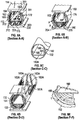
- FIGS. 6A-6D are cross-sectional views of the heat pipe 100 of FIG. 3 according to certain aspects of the present disclosure.
- FIG. 6A shows the wick insert element 152 disposed within the outer tube 112 at location A-A.
- the wick insert 152 in the evaporator portion 110 may be graded by the use of a splitter 115 that separates the liquid passage into two or more distinct sub-passages 202 and 203.
- the wick insert 152 contacts the inner wall of the outer tube 112, which comprises grooves 113, at the lateral corners of the separator plate 160 and the tips of the tabs 162 and the divider 115. The contact between the corners of the separator plate 160 and the grooves 113 is discussed in greater detail with respect to FIG. 6E .
- Vent holes 172 in the region over the divider 115. Vent holes should have a diameter that is greater than or equal to the capillary pumping dimension of the liquid passage, which may be characterized by either the hydraulic diameter or the largest circle that can be inscribed within a cross-section of the liquid passage taken perpendicular to the tube centerline. Vent holes 172 are discussed in greater detail with respect to FIGS. 9A and 10A .
- splitter 115 increases the capillary pressure difference, i.e. capillary pumping, between liquid flows in sub-passages 202 and 203 and the vapor flow in gas-phase passage 201 compared to a single combined passage such as shown in FIG .6B .
- the smaller liquid-phase arteries 202, 203 permit the use of smaller vent holes 172, compared to the vent hole 174 of a single liquid-phase artery.
- the capillary pressure is inversely proportional to the capillary pumping radius, where the capillary pumping radius is the maximum radius of curvature of the meniscus formed between the vapor and liquid phases. As the largest radius is typically at the vent holes 172, 174, the size of the vent hole determines the local capillary pressure.
- the increase in capillary pressure more than offsets the increased flow resistance caused by the reduction in flow area of a liquid-phase artery 202 compared to the area of a single liquid-phase artery.
- the performance of the heat pipe 100 may be optimized for any set of temperature, fluid and geometric constraints.
- FIG. 6B shows the wick insert element 152 disposed within the outer tube 112 at location B-B.
- the divider 115 does not extend the full length of the evaporator 110 and is not present at location B-B, leaving a single liquid-phase artery 204 that is in fluid communication with the arteries 202 and 203.
- there is a liquid-phase flow 235 that will divide into flows 225 and 230 when the flow 235 reaches the divider 115.
- the separator plate 160 has vent holes 174, which may be larger than the vent holes 172, that are discussed in greater detail with respect to FIGS. 9B and 10B .
- the labels F-F indicate the location of the enlarged view of FIG. 6E .
- FIG. 6C depicts the attachment of the attachment tabs 180 of the wick insert element 154 to the outer tube 132 of the condenser portion 130 by, for example, spot welds 182. Also visible is the extension 160A that, in this example, is underneath the separator plate 161 such that that extension 160A is captured between the inner wall of the outer tube 132 and the separator plate 161.
- FIG. 6D is a combination of a cross-sectional view and a cutaway view of the portion of the condenser portion 130 beyond location D-D.
- the outer tube 132 has grooves 133 on the inner wall, similar to the grooves 113 of outer tube 112.
- the separation plate 161 has an inclined portion 161A that tapers in width to maintain contact with the grooves 133.
- the tabs 163A must be longer than tabs 163 to maintain contact at their tips with the inner wall of the outer tube 132.
- the inclined portion 161A of the separator plate 161 is discussed in greater detail with respect to FIG. 7 .
- FIG. 6E is an enlargement of a detail F-F of FIG. 6B according to certain aspects of the present disclosure.
- the inner wall of the outer tube 112 comprises generally circumferential grooves 113.
- the grooves 113 are formed in a spiral pattern.
- the grooves have a depth "t," for example 0.13 mm (0.005 in.), chosen to transport the liquid-phase working fluid from the liquid-phase artery, for example artery 235 of FIG. 6B , around the entire circumference of the gas-phase passage 201 by capillary action of the working fluid.
- the separator plate 160 comprises lateral corners 166 that are generally in contact with the tops of the grooves 113 such that the only passages connecting the liquid-phase passages and the gas-phase passage 201 within the evaporator portion 110 are the grooves 113.
- the condenser portion 130 has grooves 133 on the inner wall of the outer tube 132 and the corresponding corners 166 of the separator plate 161 are in contact with the tops of the grooves 133 such that the grooves 133 form the only passages connecting the liquid-phase passage 235 and the gas-phase passage 201 within the condensor portion 130.
- FIG. 7 is a cutaway view of a portion of the condenser portion 130 of the heat pipe 100 of FIG. 3 according to certain aspects of the present disclosure.
- an inclined portion of the separator plate 161A is tapered thereby forming a gradually larger gas-phase passage 201.
- the end and sides of the tapered/inclined portion of the separator plate 161A are held against the inner walls of the outer tube 132 by the longer tabs 163A.
- This tapered portion of the separator plate 161A permits the enlargement of a liquid slug 150 that is disposed within the end of the condenser portion 130.
- the inclined portion 161A has an outermost tip 167 that is in contact with the inner surface of the outer tube 132 such that the liquid-phase artery 204 is terminated at the outermost tip of the inclined portion 161A.
- FIGS. 8A-8C are cross-sectional views of an example heat pipe 300 illustrating the movement of the working fluid according to certain aspects of the present disclosure.
- the heat transferred to the heat pipe from the external heat source causes the liquid working fluid 350, which has followed the circumferential grooves 311 of the tube 312 to cover the inner surface of the gas-phase passage 360, to evaporate which increases the pressure of the gaseous working fluid 351 in the evaporator portion 310 thereby causing the gaseous working fluid 351 to flow towards the condenser portion 330 as indicated by the arrows labeled "VAPORS.”
- the condenser portion 330 the flow of heat out of the condenser portion 330, for example into the radiation panels 52 of FIG.
- NCGs non-condensable gases
- FIG. 8B is a cross-sectional view of the heat pipe 300 at location 8B-8B shown in FIG. 8A , with the view of FIG. 8B taken at right angles to the view of FIG. 8A .
- the gaseous working fluid 351 is passing along the grooves 311 from the liquid-phase artery 370 past the separation plate 160 into the gas-phase passage 360 as well as evaporating directly from the grooves on the inner wall of the gas-phase passage 360.
- FIG. 8C is a cross-sectional view of the heat pipe 300 at location 8C-8C shown in FIG. 8A , with the view of FIG. 8C taken at right angles to the view of FIG. 8A .
- the liquid working fluid 350 is passing from the walls of the gas-phase passage 360, where the gaseous working fluid 351 condensed, along the grooves 331 past the separation plate 161 into the liquid-phase artery 370.
- FIGS. 9A-9B are cross-sections of an example evaporation portion 410 of a heat pipe 400 showing the size of inscribed circles within the liquid-phase arteries 402, 403 according to certain aspects of the present disclosure.
- FIG. 9A depicts an outer tube 412 with a wick insert 452 having a separation plate 462 forming a gas-phase passage 401 and a single liquid-phase artery 402.
- the largest circle that can be inscribed within the cross-sectional area of the liquid-phase artery 402 is shown as the dashed-line circle 440.
- FIG. 9B depicts an evaporation portion 410A similar to the evaporation portion 410 of FIG.9A with the addition of a divider 415 disposed beneath separation plate 462 so as to form two separate liquid-phase arteries 403 that are, in this example, of equal size.
- the liquid-phase arteries may be of different sizes.
- the largest circles that can be inscribed within the cross-sectional area of each of the liquid-phase arteries 403 are shown as the dashed-line circles 442, which are smaller than the circle 440 for a comparable configuration of a separator plate 460 within a tube 412.
- FIGS. 10A-10B are cross-sectional side views of the example heat pipe 400 illustrating exemplary vent holes 472, 474 according to certain aspects of the present disclosure.
- FIG. 10A corresponds to the evaporation portion 410 of FIG. 9A , having a single liquid-phase artery 402.
- the largest spherical bubble 480 that can form in the liquid-phase artery 402 will be approximately equal to the largest inscribed circle 440 depicted in FIG. 9A .
- the bubble 480 becomes elongated, i.e.
- the vent hole 472 must be is greater than or equal to the capillary pumping dimension of the liquid-phase passage 402, which may be characterized by either the hydraulic diameter of the liquid-phase artery 402 or the largest circle 440 that can be inscribed within a cross-section of the liquid-phase artery 402 of FIG. 9A .
- the bubble's resistance to movement may increase significantly and may become fixed in the liquid-phase artery 402, thereby blocking the liquid-phase artery 402 and causing the heat pipe 400 to function at a reduced level of performance or, if the bubble 480 completely blocks flow through the liquid-phase artery 402, to stop working altogether.
- the vent hole 472 is circular and the diameter of the vent hole 472 must be greater than or equal to a diameter of the inscribed circle 440.
- vent holes 472 may be placed along the liquid-phase artery 402 to provide multiple opportunities for the bubble 480 to vent as the bubble 480 progresses down the liquid-phase artery 402, but a single vent hole 472 may be sufficient, in certain embodiments, to maintain proper heat pipe operation.
- FIG. 10B corresponds to the evaporation portion 410A of FIG. 9B , having two liquid-phase arteries 403 separated by a divider 415. Similar to the embodiment of FIG. 10A , the vent hole 474 must be at least the same size as the largest inscribed circle 442 of FIG. 9B in order to reliably release the bubble 480 into the gas-phase passage 401 before the bubble 480 becomes elongated within the liquid-phase arteries 403.
- the vent hole 474 is circular and the diameter of the vent hole 474 must be greater than or equal to the capillary pumping dimension of the liquid-phase arteries 403, which may be characterized by either the hydraulic diameter of the liquid-phase arteries 403 or the largest circle 442 that can be inscribed within a cross-section of the liquid-phase artery 403.
- each separate passage 403 must have at least one vent hole 474 to maintain operability in the presence of gas bubbles 480.
- the diameters of the vent holes 474 may be smaller than the diameter of the vent hole 473 in the single liquid-phase artery of FIG. 10A .
- FIG. 11 depicts an alternate configuration of a heat pipe 500 according to certain aspects of the present disclosure.
- Two narrow and opposing indents 490 penetrate outwards into the walls 432 of one or both of the evaporator portion 110 and the condenser portion 130.
- Each indent 490 provides a relatively small gap on the container internal surface into which a wick insert 490 is placed and retained.
- the wick insert extension 492 may fit under the wick insert 490, similar to the configuration of extension 160A and separator plate 161 shown in FIG. 4 , and into the same indents 490.
- FIGS. 12A-12C depict an exemplary configuration of a wick insert 550 within a bellows tube 590 in a flexible portion 520 of a heat pipe according to certain aspects of the present disclosure.
- FIG. 12A depicts a partial cutaway view of a flexible portion 520 of a heat pipe, showing a braided sleeve 592 surrounding a bellows tube 590 within which is disposed a wick insert 550 and a spring 596, similar to the flexible portion 120 of FIG. 5 .
- the separator plate 560 of the wick insert 550 separates the gas-phase passage 601 from the liquid-phase artery 604.
- the labels G-G indicate the location of the view of FIG. 12B .
- FIG. 12B is a cross-sectional view of the complete flexible portion 520.
- the lateral corners 566 of the separator plate 560 are generally in contact with the inner edges 561 of the individual bellows that form the bellows tube 590, wherein this line of contact separates the gas-phase passage 601 from the liquid-phase artery 604.
- the dashed-line circle 640 represents the largest inscribed circle that can be formed within the liquid-phase artery 604, with the circle 640 having a diameter 641.
- the labels H-H indicate the location of the view of the flexible portion 520 of FIG. 12B that is shown in FIG. 12C .
- FIG. 12C is a cross-section view of the complete flexible section 520 of FIG. 12A as indicated by the labels H-H in FIG. 12B .
- the corner 566 of the separator plate 560 is generally in contact with the inner edges 561, thus creating an opening 650, one of which is shown as a cross-hatched area in FIG. 12C , on each side of each individual bellows, i.e. the individual convolution of the bellows tube 590 that connects the gas-phase passage 601 to the liquid-phase artery 604.
- the size of the opening 650 must be limited to have less effect on the pumping characteristics of the liquid-phase artery 604 than the vent hole 562 formed in the separation plate 560.
- vent opening 562 is circular and have a minimum diameter equal or greater than the diameter 641 of the inscribed circle 640 shown in FIG. 12B
- the opening 650 is not a circular shape and so does not have a single "diameter.”
- the opening 650 does have a "hydraulic diameter,” however, and the effect of the opening 650 on the pumping characteristics of the liquid-phase artery 604 will be less than that of the vent hole 562 having a diameter 641 if the hydraulic diameter of the opening 650 is less than the diameter 641.
- the thickness and depth of the individual bellows of the bellows tube 590 are therefore based at least partially on achieving a hydraulic diameter for the openings 650 that is less than the diameter 641 of largest circle 640 that can be inscribed in the liquid-phase artery 604.
- FIGS. 13A-13B depict another embodiment of a flexible wick insert 700 that can be bent in multiple directions according to certain aspects of the present disclosure.
- FIG. 13A is a perspective view of the wick insert 700 that is comprises of a separation plate 710 with, in this embodiment, vent holes 714 formed in the solid portions 712 on either side of the flexible portion 711.
- This embodiment includes several tabs 720 spaced along the wick insert 700 that serve to hold the wick insert in place within a bellows tube, e.g. the bellows tube 590 of FIG. 12A , in place of the spring 596.
- the tabs 720 are used with a spring, e.g. the spring 596 of FIG. 12A .
- a portion 13B of the wick insert 700 is enlarged in FIG. 13B .
- the tabs 720 are welded to the separation plate 710.
- the tabs 720 may be coupled to the separation plate using other attachment methods known to those of skill in the art, e.g. mechanically interlocking, brazing, soldering, etc.
- FIG. 13B shows a portion of the wick insert 700 where a plurality of slots 714 alternately extend inward from the lateral edges 713 to create a serpentine form in the separation plate 710.
- the portions of the serpentine form that are aligned parallel to a centerline 740 of the separation plate 710 have a first width 718.
- the portions of the serpentine form that are perpendicular to the centerline 740 have a second width 716.
- the slots 714 extend past the centerline 740.
- the first and second widths 718, 716 are approximately equal. In certain embodiments, the first width 718 is less than the second width 716.
- the slots 714 increase the lateral flexibility of the wick insert 700 in a plane that is parallel to the separation plate 710 and passes through both lateral edges 713.
- a flexible portion of a heat pipe that includes the wick insert 700 may be locally bent in any plane that passes through the centerline 740.
- a flexible portion of a heat pipe that includes the wick insert 700 may be sequentially bent along its length in different planes that each pass through the centerline 740.
- the portion of the wick insert 700 that is located within a condenser portion or evaporator portion, e.g. sections 110, 130 of heat pipe 100 in FIG. 3 may have slots 714 such that the condenser portion or evaporator portion can be bent or formed into a particular shape after assembly.
- the degree of flexibility and the minimum radius of curvature that can be achieved while bending either the rigid condenser or evaporator portions or the flexible portion of a heat pipe may be a function of one or more of the spacing and the length of the slots.
- the disclosed examples of a heat pipe are particularly suitable for use in a low-gravity environment.
- vent holes having diameters that are greater than or equal to the largest circle that can be inscribed in the liquid-phase artery located below the respective vent hole reduces the likelihood of a gas bubble obstructing the artery by venting such gas bubbles before they become lodged in the artery.
- the use of dividers to create multiple small liquid-phase arteries in place of a single, larger liquid-phase artery improves the heat transfer capability of a heat pipe by grading the pumping characteristics of the liquid-phase arteries.
- Headings and subheadings, if any, are used for convenience only and do not limit the invention.
- top should be understood as referring to an arbitrary frame of reference, rather than to the ordinary gravitational frame of reference.
- a top surface, a bottom surface, a front surface, and a rear surface may extend upwardly, downwardly, diagonally, or horizontally in a gravitational frame of reference.
- angles formed between the referenced components can be greater or less than 90 degrees in some embodiments.
- a phrase such as an "aspect” does not imply that such aspect is essential to the subject technology or that such aspect applies to all configurations of the subject technology.
- a disclosure relating to an aspect may apply to all configurations, or one or more configurations.
- a phrase such as an aspect may refer to one or more aspects and vice versa.
- a phrase such as an “embodiment” does not imply that such embodiment is essential to the subject technology or that such embodiment applies to all configurations of the subject technology.
- a disclosure relating to an embodiment may apply to all embodiments, or one or more embodiments.
- a phrase such as an embodiment may refer to one or more embodiments and vice versa.
- the Writing contains the following concepts:
Landscapes
- Engineering & Computer Science (AREA)
- Life Sciences & Earth Sciences (AREA)
- Sustainable Development (AREA)
- Physics & Mathematics (AREA)
- Thermal Sciences (AREA)
- Mechanical Engineering (AREA)
- General Engineering & Computer Science (AREA)
- Biodiversity & Conservation Biology (AREA)
- Health & Medical Sciences (AREA)
- Environmental & Geological Engineering (AREA)
- Environmental Sciences (AREA)
- General Health & Medical Sciences (AREA)
- Toxicology (AREA)
- Remote Sensing (AREA)
- Aviation & Aerospace Engineering (AREA)
- Cooling Or The Like Of Semiconductors Or Solid State Devices (AREA)
- Heat-Exchange Devices With Radiators And Conduit Assemblies (AREA)
Abstract
Description
- Not applicable.
- Statement Regarding Federally Sponsored Research or Development
- This invention was made with government support under Contract No. NASW-4884 awarded by the National Aeronautics and Space Administration (NASA). The government has certain rights in the invention.
- The present invention generally relates to heat-transfer systems and, in particular, to a bendable heat pipe having an axial wick insert.
- In conventional heat pipes, a liquid-phase working fluid is provided to an evaporator whereupon the working fluid extracts heat from the evaporator and is converted to a vapor-phase by evaporation. The vapor-phase working fluid is conveyed to a condenser wherein the working fluid rejects hear to a heat sink by condensation and is thereby returned to the liquid-phase.
- Some conventional heat pipes, particularly heat pipes intended for use in low-gravity environments utilize arteries, i.e. channels, to provide capillary pressure to circulate the liquid-phase working fluid from the condenser to the evaporator. Some low-gravity heat pipes provide arterial wicks wherein the arteries carrying the liquid-phase working fluid are separated from the gas-phase region by a capillary-scale slot or a fine-weave mesh. Conventional arterial heat pipes, however, are susceptible to bubble-induced failures and, in addition, may fail to prime properly in a low-gravity environment. Bubbles may form in the liquid working fluid, such bubbles being particularly persistent in the presence of non-condensable gases, i.e. gases other than the heat pipe working fluid, that may be present as impurities or may evolve by chemical reaction during operation of the heat pipe.
- Certain conventional arterial heat pipes may provide one or more wicks as an insert within the gas-phase region of the heat pipe. Wick inserts having machined structures may have limited flexibility, thereby presenting a challenge for use in deployable heat management systems, and inserted wick inserts having porous structures may have substantially lower heat transport capabilities, thereby presenting a challenge for use in a high-performance system such as may be required on space vehicles.
- The present invention generally relates to heat-transfer systems and, in particular, to a bendable heat pipe having an axial wick insert.
- It is desirable to provide a high-transport heat pipe for use in a low-gravity environment without sensitivity to blockage of liquid arteries by gas bubbles. It may also be desirable to provide a high-transport heat pipe having a flexible portion(s) allowing for deployment of one or more attached sections such as a radiator assembly coupled to the condenser portion. It may also be desirable to provide such a heat pipe to provide mechanical isolation between elements of sensitive instruments. In an example envisioned application, a deployed radio frequency (RF) payload wing may transfer excess heat through a flexible heat pipe to the spacecraft radiators.
- In certain embodiments, a heat pipe is disclosed that includes an evaporator portion, a condenser portion, and at least one flexible portion sealingly coupled between the evaporator portion and the condenser portion. The at least one flexible portion includes a flexible tube having a plurality of inner contact points and a flexible separator plate comprising two lateral edges that are disposed proximate to the inner contact points of the tube so as to divide the interior volume into a gas-phase passage and a liquid-phase artery. The separator plate has a first plane that passes through the two lateral edges when the separator plate is flat. The separator plate and flexible tube are configured such that the at least one flexible portion is flexible at least in a second plane that is perpendicular to the first surface.
- In certain embodiments, an evaporator portion of a heat pipe is disclosed that includes a tube comprising an interior volume with an inner surface and a centerline, a separator plate disposed within the tube and comprising two lateral edges that are proximate to the inner surface of the tube so as to divide the interior volume into a gas-phase passage and a liquid-phase artery, and a vent hole formed through the separator plate so as to connect the gas-phase passage to the liquid-phase artery. The vent hole has a diameter that is greater than or equal to a diameter of the largest circle that can be inscribed within the liquid-phase artery in a cross-section of the tube taken perpendicular to the centerline.
- In certain embodiments, an evaporator portion of a heat pipe is disclosed that includes a tube comprising an interior volume with an inner surface and a separator plate disposed within the tube and comprising two lateral edges that are proximate to the inner surface of the tube so as to divide the interior volume into a gas-phase passage and a liquid-phase artery. The separator plate includes a plurality of tabs projecting toward the gas-phase passage from both of the lateral edges of the separator plate. Each tab has a tip that is proximate to the inner surface of the tube. The tabs are configured to urge the separator plate downward so as to maintain the two lateral edges proximate to the inner surface of the tube.
- In certain embodiments, an evaporator portion of a heat pipe is disclosed that includes a tube comprising an interior volume with an inner surface, a separator plate disposed within the tube and comprising two lateral edges that are proximate to the inner surface of the tube so as to divide the interior volume into a gas-phase passage and a liquid-phase artery, and a splitter disposed within the liquid-phase artery in contact with the separator plate and the inner surface of the tube so as to divide the liquid phase artery into a plurality of liquid-phase subarteries.
- In certain embodiments, a condenser portion of a heat pipe is disclosed that includes a tube comprising an interior volume with an inner surface and a separator plate disposed within the tube, the separator plate comprising two lateral edges that are proximate to the inner surface of the tube so as to divide the interior volume into a gas-phase passage and a liquid-phase artery. The separator plate also has a first portion having a constant size of the gas-phase passage and a second portion that is inclined within the tube and configured such that the gas phase passage becomes larger toward an outermost end of the tube.
- The accompanying drawings, which are included to provide further understanding and are incorporated in and constitute a part of this specification, illustrate disclosed embodiments and together with the description serve to explain the principles of the disclosed embodiments. In the drawings:
-
FIG. 1 depicts a spacecraft using a conventional fixed heat pipe radiator. -
FIG. 2 depicts a deployable radiator that is coupled to a plurality of exemplary heat pipes according to certain aspects of the present disclosure. -
FIG. 3 is a perspective view of an exemplary heat pipe according to certain aspects of the present disclosure. -
FIG. 4 is a perspective view of an exemplary wick insert according to certain aspects of the present disclosure. -
FIG. 5 is a cutaway view of the flexible portion of the heat pipe ofFIG. 3 in both the straight and flexed positions according to certain aspects of the present disclosure. -
FIGS. 6A-6D are cross-sectional views of the heat pipe ofFIG. 3 according to certain aspects of the present disclosure. -
FIG. 6E is an enlargement of a detail F-F ofFIG. 6B according to certain aspects of the present disclosure. -
FIG. 7 is a cutaway view of a portion of the condenser portion of the heat pipe ofFIG. 3 according to certain aspects of the present disclosure. -
FIGS. 8A-8C are cross- sectional views of an example heat pipe illustrating the movement of the working fluid according to certain aspects of the present disclosure. -
FIGS. 9A-9B are cross-sections of an example evaporation portion of a heat pipe showing the size of inscribed circles within the liquid-phase arteries according to certain aspects of the present disclosure. -
FIGS. 10A-10B are cross-sectional side views of the example heat pipe illustrating exemplary vent holes according to certain aspects of the present disclosure. -
FIG. 11 depicts an alternate configuration of a heat pipe according to certain aspects of the present disclosure. -
FIGS. 12A-12C depict an exemplary configuration of a wick insert within a bellows tube in a flexible portion of a heat pipe according to certain aspects of the present disclosure. -
FIGS. 13A-13B depict another embodiment of a flexible wick insert that can be bent in multiple directions according to certain aspects of the present disclosure. - The present invention generally relates to heat-transfer systems and, in particular, to a bendable heat pipe having an axial wick insert.
- The following description discloses embodiments of a heat pipe that is particularly adapted for use on a spacecraft in a low-gravity environment. In certain embodiments, the heat pipe includes a flexible section allowing a radiator assembly to be deployed thereby improving the heat rejection capability of the radiator assembly.
- The detailed description set forth below is intended as a description of various configurations of the subject technology and is not intended to represent the only configurations in which the subject technology may be practiced. The appended drawings are incorporated herein and constitute a part of the detailed description. The detailed description includes specific details for the purpose of providing a thorough understanding of the subject technology. However, it will be apparent to those skilled in the art that the subject technology may be practiced without these specific details. In some instances, well-known structures and components are shown in block diagram form in order to avoid obscuring the concepts of the subject technology. Like components are labeled with identical element numbers for ease of understanding.
-
FIG. 1 depicts aspacecraft 10 using a conventional fixedheat pipe radiator 12. Theradiator 12 can reject heat in only a single direction away from the body of thespacecraft 10, as the opposite side of theradiator 12 is facing the spacecraft itself. -
FIG. 2 depicts a deployable radiator 50 that is coupled to a plurality ofexemplary heat pipes 100 according to certain aspects of the present disclosure. The radiator 50 is part of aheat management system 40 of thespacecraft 20. Theflexible heat pipes 100 enable thecondenser portion 130 to extend away from a stowed position to a deployed position extending away from the spacecraft, . The radiator 50 is stowed inrecess 22 at launch and then deployed after thespacecraft 20 is in orbit. Theheat pipes 100 each comprise acondenser portion 110 coupled toradiation panels 52 on both sides, where thepanel 52 on the near side has been cut away to reveal thecondenser portions 110. Theradiator panels 52 are configured to distribute the heat from thecondenser portions 110 across the surface of thepanel 52 and effectively radiate the heat to an external heat sink, for example deep space, using principles known to those of skill in the art. With apanel 52 on each side, the heat rejection capability of the radiator 50 may be greater than the single-sided radiator 12 ofFIG. 1 . Theheat pipes 100 each also comprise anevaporator portion 130 coupled to acold plate 54 on both sides, in this example, where thepanel 54 on the near side has been cut away to reveal theevaporator portions 130. Thepanels 54 absorb heat from internal components (not shown inFIG. 2 ) and transfer the heat to theevaporator portions 130. Thecondenser portions 110 andevaporator portions 130 are connected byflexible portions 120, the construction of which is discussed in greater detail with respect toFIG. 5 . -
FIG. 3 is a perspective view of anexemplary heat pipe 100 according to certain aspects of the present disclosure. Theheat pipe 100 comprises acondenser portion 110, aflexible portion 120, and aevaporator portion 130, withend caps 140 sealing the outer ends of thecondenser portion 110 and theevaporator portion 130. Each of thecondenser portion 110 and theevaporator portion 130 have an outer end and an inner end, wherein the inner end is closest to the other of thecondenser portion 110 and theevaporator portion 130. In certain embodiments, thecondenser portion 110 and theevaporator portion 130 comprise anouter tube flexible portion 120, provide a single axial chamber that is, in certain embodiments, generally circular in cross-section. In certain embodiments, thetubes end cap 140. The internal construction of thevarious portions surfaces 114 and 134 are adapted to be thermally coupled to thepanels heat pipe 100 is assembled into a heat management system such assystem 40 ofFIG. 2 . The labels A-A through D-D indicate the locations of cross-sectional views ofFIGS. 6A-6D , respectively. -
FIG. 4 is a perspective view of anexemplary wick insert 150 according to certain aspects of the present disclosure. In this embodiment, the wick insert comprises twoelements Element 152 comprises aseparator plate 160 and a plurality oftabs 162 extending from alower tab portion 164 on each side of theseparator plate 160.Element 154 comprises asimilar separator plate 161 and a plurality oftabs 163 extending from alower tab portion 165 on each side of theseparator plate 161. Thewick insert element 154 comprises aninclined portion 161A andextended tabs 163A, which are discussed in greater detail with respect toFIG. 7 . In this example, theseparator plate 160 ofelement 152 comprises anextension 160A that will be disposed within theflexible portion 120 when theheat pipe 100 is assembled. In certain embodiments, theextension 160A does not have thelower tab portion 164 or thetabs 162. In certain embodiments, theextension 160A extends into theevaporator portion 130 when theheat pipe 100 is assembled and overlaps theseparator plate 161 of theelement 154. The function of this overlap is discussed in greater detail with respect toFIG. 5 . In certain embodiments, theelements attachment tabs 180 configured to be attached to theflexible portion 120 so as to locate thewick insert 150 with respect to theflexible portion 120 and prevent displacement of thewick insert 150 as theheat pipe 100 bends. The attachment ofattachment tabs 180 is discussed in greater detail with respect toFIG. 6C . Vent holes 170 are visible in theseparator plate 160 of theevaporator portion 110, and are discussed in greater detail with respect toFIGS. 10A & 10B . The labels E-E indicate the location of the cross-sectional view shown inFIG. 7 . Awick insert 150 may be particularly advantageous for use withouter tubes FIG. 11 , to locate a wick insert. -
FIG. 5 is a cutaway view of theflexible portion 120 of theheat pipe 100 ofFIG. 3 in both the straight and flexed positions according to certain aspects of the present disclosure. The exampleflexible portion 120 comprises abellows tube 190 coupled to acollar 194 at each end. In certain embodiments, theouter tubes condenser portion 110 andevaporator portion 130 are also coupled to thecollars 194 when theheat pipe 100 is assembled, thereby forming the sealed singleaxial chamber 200. In certain embodiments, thebellows tube 190 comprises a plurality of radially outward extending convexly curved elements along the length of thebellows tube 190 which are connected to each other by concavely curved inner portions, i.e. individual bellows. In certain embodiments, theflexible portion 120 comprises a surroundingbraided sleeve 192 that is also coupled to thecollars 194. - The wick insert
elements outer tubes wick insert element 152 extends through thebellow tube 190 and into theouter tube 132 whereextension 160A overlaps theseparator plate 161 of thewick insert 154. The wick inserts 152, 154 acts as barrier to form two distinct passages within theouter tubes tube 190. As theflexible portion 150 moves from the straight position to the flexed position, the elements of theflexible portion 150 bend about aneutral axis 151. Elements that are on an outer side of theneutral axis 151 will tend to stretch while elements that are on an inner side of theneutral axis 151 will tend to compress. As theseparator plates neutral axis 151, theseparator plate 160 will pull away from theseparator plate 161. The overlap of theextension 160A with theseparator plate 161 maintains the continuity of theseparator plates axial chamber 200. The ability to maintain the continuity of theseparator plates axial chamber 200 that are above and below theseparations plates heat pipe 100 to be bent after fabrication while maintaining its heat transfer capability. - In the example embodiment, a
spring 196 is disposed inside and constrained by thebellows 190 in the vapor-phase portion of the singleaxial chamber 200. Thespring 196 is also constrained by thewick insert element 152. Thespring 196 enables thewick insert element 152 to deform during flexure without buckling. As shown inFIG. 5 , in the flexed position thebellows 190 and thespring 196 are bent so that at their radial edges thebellows 190 have a compressed inner side and an expanded outer side near the inner walls of thebraided sleeve 192. Similarly, thespring 196 has an expanded radial edge and a compressed radial edge. As depicted inFIG. 5 , the expanded spring radial edge is disposed against theseparator plate 160 of thewick insert element 152 and the compressed spring radial edge is disposed against thebellows 190 inner diameter. It will be apparent to those of skill in the art that theflexible portion 120 may also be bent in the opposite manner where the expanded spring radial edge is disposed against thebellows 190 inner diameter and the compressed spring radial edge is disposed against theseparator plate 160. -
FIGS. 6A-6D are cross-sectional views of theheat pipe 100 ofFIG. 3 according to certain aspects of the present disclosure.FIG. 6A shows thewick insert element 152 disposed within theouter tube 112 at location A-A. Thewick insert 152 in theevaporator portion 110 may be graded by the use of asplitter 115 that separates the liquid passage into two or moredistinct sub-passages wick insert 152 contacts the inner wall of theouter tube 112, which comprisesgrooves 113, at the lateral corners of theseparator plate 160 and the tips of thetabs 162 and thedivider 115. The contact between the corners of theseparator plate 160 and thegrooves 113 is discussed in greater detail with respect toFIG. 6E . In operation, there will be a gas-phase flow 220 in the gas-phase passage 201 that is above theseparator plate 160 and liquid-phase flows 225 and 230 in thearteries separator plate 160 hasvent holes 172 in the region over thedivider 115. Vent holes should have a diameter that is greater than or equal to the capillary pumping dimension of the liquid passage, which may be characterized by either the hydraulic diameter or the largest circle that can be inscribed within a cross-section of the liquid passage taken perpendicular to the tube centerline. Vent holes 172 are discussed in greater detail with respect toFIGS. 9A and 10A . - The use of
splitter 115 increases the capillary pressure difference, i.e. capillary pumping, between liquid flows insub-passages phase passage 201 compared to a single combined passage such as shown inFIG .6B . The smaller liquid-phase arteries vent hole 174 of a single liquid-phase artery. The capillary pressure is inversely proportional to the capillary pumping radius, where the capillary pumping radius is the maximum radius of curvature of the meniscus formed between the vapor and liquid phases. As the largest radius is typically at the vent holes 172, 174, the size of the vent hole determines the local capillary pressure. The increase in capillary pressure more than offsets the increased flow resistance caused by the reduction in flow area of a liquid-phase artery 202 compared to the area of a single liquid-phase artery. By placement of one or moresuch splitters 115, the performance of theheat pipe 100 may be optimized for any set of temperature, fluid and geometric constraints. -
FIG. 6B shows thewick insert element 152 disposed within theouter tube 112 at location B-B. In theheat pipe 100 ofFIG. 3 , thedivider 115 does not extend the full length of theevaporator 110 and is not present at location B-B, leaving a single liquid-phase artery 204 that is in fluid communication with thearteries phase flow 235 that will divide intoflows flow 235 reaches thedivider 115. In the region where there is nodivider 115, theseparator plate 160 has vent holes 174, which may be larger than the vent holes 172, that are discussed in greater detail with respect toFIGS. 9B and 10B . The labels F-F indicate the location of the enlarged view ofFIG. 6E . -
FIG. 6C depicts the attachment of theattachment tabs 180 of thewick insert element 154 to theouter tube 132 of thecondenser portion 130 by, for example, spot welds 182. Also visible is theextension 160A that, in this example, is underneath theseparator plate 161 such that thatextension 160A is captured between the inner wall of theouter tube 132 and theseparator plate 161. -
FIG. 6D is a combination of a cross-sectional view and a cutaway view of the portion of thecondenser portion 130 beyond location D-D. Theouter tube 132 hasgrooves 133 on the inner wall, similar to thegrooves 113 ofouter tube 112. Beyond location D-D, theseparation plate 161 has aninclined portion 161A that tapers in width to maintain contact with thegrooves 133. As theinclined portion 161A of theseparator plate 161 descends, thetabs 163A must be longer thantabs 163 to maintain contact at their tips with the inner wall of theouter tube 132. Theinclined portion 161A of theseparator plate 161 is discussed in greater detail with respect toFIG. 7 . -
FIG. 6E is an enlargement of a detail F-F ofFIG. 6B according to certain aspects of the present disclosure. In certain embodiments, the inner wall of theouter tube 112 comprises generallycircumferential grooves 113. In certain embodiments, thegrooves 113 are formed in a spiral pattern. In certain embodiments, the grooves have a depth "t," for example 0.13 mm (0.005 in.), chosen to transport the liquid-phase working fluid from the liquid-phase artery, forexample artery 235 ofFIG. 6B , around the entire circumference of the gas-phase passage 201 by capillary action of the working fluid. Theseparator plate 160 compriseslateral corners 166 that are generally in contact with the tops of thegrooves 113 such that the only passages connecting the liquid-phase passages and the gas-phase passage 201 within theevaporator portion 110 are thegrooves 113. In certain embodiments, there may be a gap between alateral corner 166 and one or more of the peaks of thegrooves 113, wherein the gap is on the same order of magnitude as thegrooves 113 and less than the diameter of the vent holes 172, 174 that are proximate to the particular gap. Similarly, thecondenser portion 130 hasgrooves 133 on the inner wall of theouter tube 132 and thecorresponding corners 166 of theseparator plate 161 are in contact with the tops of thegrooves 133 such that thegrooves 133 form the only passages connecting the liquid-phase passage 235 and the gas-phase passage 201 within thecondensor portion 130. -
FIG. 7 is a cutaway view of a portion of thecondenser portion 130 of theheat pipe 100 ofFIG. 3 according to certain aspects of the present disclosure. At the outermost end of thecondenser portion 130, an inclined portion of theseparator plate 161A is tapered thereby forming a gradually larger gas-phase passage 201. The end and sides of the tapered/inclined portion of theseparator plate 161A are held against the inner walls of theouter tube 132 by thelonger tabs 163A. This tapered portion of theseparator plate 161A permits the enlargement of aliquid slug 150 that is disposed within the end of thecondenser portion 130. This enlargement of theliquid slug 150 reduces the zero-g capillary back-pressure, since the capillary pressure is inversely proportional to the radius of curvature of themeniscus 252 formed by theliquid slug 250 in the gas-phase passage 201. The increased pressure drop caused by the reduction of area in the liquid-phase artery 204 under the inclined portion of theseparator plate 161A is more than offset by the increased net capillary pressure resulting from the larger radius of themeniscus 252. Such tapering may be optimized based on net heat pipe performance requirements using a variety of taper configurations. In certain embodiments, theinclined portion 161A has anoutermost tip 167 that is in contact with the inner surface of theouter tube 132 such that the liquid-phase artery 204 is terminated at the outermost tip of theinclined portion 161A. -
FIGS. 8A-8C are cross-sectional views of anexample heat pipe 300 illustrating the movement of the working fluid according to certain aspects of the present disclosure. In theevaporator portion 310, shown in the left portion ofFIG. 8A , the heat transferred to the heat pipe from the external heat source causes theliquid working fluid 350, which has followed thecircumferential grooves 311 of thetube 312 to cover the inner surface of the gas-phase passage 360, to evaporate which increases the pressure of the gaseous workingfluid 351 in theevaporator portion 310 thereby causing the gaseous workingfluid 351 to flow towards thecondenser portion 330 as indicated by the arrows labeled "VAPORS." In thecondenser portion 330, the flow of heat out of thecondenser portion 330, for example into theradiation panels 52 ofFIG. 2 , causes the gaseous workingfluid 351 to condense on thegrooves 331 of the tube 332 into theliquid working fluid 350 and flow along thegrooves 331 into the liquid-phase artery 370. Capillary pressure differences cause theliquid working fluid 350 to flow in the liquid-phase artery 370 towards theevaporator portion 310. Bubbles 357 of non-condensable gases (NCGs) that form in theliquid working fluid 350 may escape into the gas-phase passage 360 via either thelarger holes 380 or thesmaller holes 385 located over a divider (not visible inFIG 8A ) at the outer end of theevaporator portion 310. -
FIG. 8B is a cross-sectional view of theheat pipe 300 atlocation 8B-8B shown inFIG. 8A , with the view ofFIG. 8B taken at right angles to the view ofFIG. 8A . The gaseous workingfluid 351 is passing along thegrooves 311 from the liquid-phase artery 370 past theseparation plate 160 into the gas-phase passage 360 as well as evaporating directly from the grooves on the inner wall of the gas-phase passage 360. -
FIG. 8C is a cross-sectional view of theheat pipe 300 atlocation 8C-8C shown inFIG. 8A , with the view ofFIG. 8C taken at right angles to the view ofFIG. 8A . Theliquid working fluid 350 is passing from the walls of the gas-phase passage 360, where the gaseous workingfluid 351 condensed, along thegrooves 331 past theseparation plate 161 into the liquid-phase artery 370. -
FIGS. 9A-9B are cross-sections of anexample evaporation portion 410 of aheat pipe 400 showing the size of inscribed circles within the liquid-phase arteries FIG. 9A depicts anouter tube 412 with awick insert 452 having aseparation plate 462 forming a gas-phase passage 401 and a single liquid-phase artery 402. The largest circle that can be inscribed within the cross-sectional area of the liquid-phase artery 402 is shown as the dashed-line circle 440. - When the
wick insert 452 is installed into thetube 412, the tips of the plurality oftabs 462 are displaced inward while in contact with the inner surface of thetube 412 such that reaction forces 453 applied by the tube to the tips of the plurality oftabs 462 together provide a netdownward force 454 on thewick insert 452. This downward force serves to maintain thelateral edges 466 in contact with or proximate to the inner surface of thetube 412. -
FIG. 9B depicts an evaporation portion 410A similar to theevaporation portion 410 ofFIG.9A with the addition of adivider 415 disposed beneathseparation plate 462 so as to form two separate liquid-phase arteries 403 that are, in this example, of equal size. In certain embodiments, the liquid-phase arteries may be of different sizes. The largest circles that can be inscribed within the cross-sectional area of each of the liquid-phase arteries 403 are shown as the dashed-line circles 442, which are smaller than thecircle 440 for a comparable configuration of aseparator plate 460 within atube 412. -
FIGS. 10A-10B are cross-sectional side views of theexample heat pipe 400 illustrating exemplary vent holes 472, 474 according to certain aspects of the present disclosure.FIG. 10A corresponds to theevaporation portion 410 ofFIG. 9A , having a single liquid-phase artery 402. The largestspherical bubble 480 that can form in the liquid-phase artery 402 will be approximately equal to the largest inscribedcircle 440 depicted inFIG. 9A . In order to reliably release thebubble 480 into the gas-phase passage 401 before thebubble 480 becomes elongated, i.e. thebubble 480 becomes longer along the liquid-phase artery 402 that thebubble 480 is wide, thevent hole 472 must be is greater than or equal to the capillary pumping dimension of the liquid-phase passage 402, which may be characterized by either the hydraulic diameter of the liquid-phase artery 402 or thelargest circle 440 that can be inscribed within a cross-section of the liquid-phase artery 402 ofFIG. 9A . Once a generallyspherical bubble 480 touches both the inner wall of theouter tube 412 and theseparator plate 460, the bubble's resistance to movement may increase significantly and may become fixed in the liquid-phase artery 402, thereby blocking the liquid-phase artery 402 and causing theheat pipe 400 to function at a reduced level of performance or, if thebubble 480 completely blocks flow through the liquid-phase artery 402, to stop working altogether. In certain embodiments, thevent hole 472 is circular and the diameter of thevent hole 472 must be greater than or equal to a diameter of the inscribedcircle 440. Multiple vent holes 472 may be placed along the liquid-phase artery 402 to provide multiple opportunities for thebubble 480 to vent as thebubble 480 progresses down the liquid-phase artery 402, but asingle vent hole 472 may be sufficient, in certain embodiments, to maintain proper heat pipe operation. -
FIG. 10B corresponds to the evaporation portion 410A ofFIG. 9B , having two liquid-phase arteries 403 separated by adivider 415. Similar to the embodiment ofFIG. 10A , thevent hole 474 must be at least the same size as the largest inscribedcircle 442 ofFIG. 9B in order to reliably release thebubble 480 into the gas-phase passage 401 before thebubble 480 becomes elongated within the liquid-phase arteries 403. In certain embodiments, thevent hole 474 is circular and the diameter of thevent hole 474 must be greater than or equal to the capillary pumping dimension of the liquid-phase arteries 403, which may be characterized by either the hydraulic diameter of the liquid-phase arteries 403 or thelargest circle 442 that can be inscribed within a cross-section of the liquid-phase artery 403. In the graded configuration ofFIG. 10B , eachseparate passage 403 must have at least onevent hole 474 to maintain operability in the presence of gas bubbles 480. The diameters of the vent holes 474 may be smaller than the diameter of the vent hole 473 in the single liquid-phase artery ofFIG. 10A . -
FIG. 11 depicts an alternate configuration of aheat pipe 500 according to certain aspects of the present disclosure. Two narrow andopposing indents 490 penetrate outwards into thewalls 432 of one or both of theevaporator portion 110 and thecondenser portion 130. Eachindent 490 provides a relatively small gap on the container internal surface into which awick insert 490 is placed and retained. In thecondenser portion 130, the wick insert extension 492 may fit under thewick insert 490, similar to the configuration ofextension 160A andseparator plate 161 shown inFIG. 4 , and into thesame indents 490. -
FIGS. 12A-12C depict an exemplary configuration of awick insert 550 within abellows tube 590 in aflexible portion 520 of a heat pipe according to certain aspects of the present disclosure.FIG. 12A depicts a partial cutaway view of aflexible portion 520 of a heat pipe, showing abraided sleeve 592 surrounding abellows tube 590 within which is disposed awick insert 550 and aspring 596, similar to theflexible portion 120 ofFIG. 5 . Theseparator plate 560 of thewick insert 550 separates the gas-phase passage 601 from the liquid-phase artery 604. The labels G-G indicate the location of the view ofFIG. 12B . -
FIG. 12B is a cross-sectional view of the completeflexible portion 520. Thelateral corners 566 of theseparator plate 560 are generally in contact with theinner edges 561 of the individual bellows that form thebellows tube 590, wherein this line of contact separates the gas-phase passage 601 from the liquid-phase artery 604. The dashed-line circle 640 represents the largest inscribed circle that can be formed within the liquid-phase artery 604, with thecircle 640 having adiameter 641. The labels H-H indicate the location of the view of theflexible portion 520 ofFIG. 12B that is shown inFIG. 12C . -
FIG. 12C is a cross-section view of the completeflexible section 520 ofFIG. 12A as indicated by the labels H-H inFIG. 12B . Thecorner 566 of theseparator plate 560 is generally in contact with theinner edges 561, thus creating an opening 650, one of which is shown as a cross-hatched area inFIG. 12C , on each side of each individual bellows, i.e. the individual convolution of thebellows tube 590 that connects the gas-phase passage 601 to the liquid-phase artery 604. The size of the opening 650 must be limited to have less effect on the pumping characteristics of the liquid-phase artery 604 than thevent hole 562 formed in theseparation plate 560. While thevent opening 562 is circular and have a minimum diameter equal or greater than thediameter 641 of the inscribedcircle 640 shown inFIG. 12B , in this example, the opening 650 is not a circular shape and so does not have a single "diameter." The opening 650 does have a "hydraulic diameter," however, and the effect of the opening 650 on the pumping characteristics of the liquid-phase artery 604 will be less than that of thevent hole 562 having adiameter 641 if the hydraulic diameter of the opening 650 is less than thediameter 641. The thickness and depth of the individual bellows of thebellows tube 590 are therefore based at least partially on achieving a hydraulic diameter for the openings 650 that is less than thediameter 641 oflargest circle 640 that can be inscribed in the liquid-phase artery 604. -
FIGS. 13A-13B depict another embodiment of aflexible wick insert 700 that can be bent in multiple directions according to certain aspects of the present disclosure.FIG. 13A is a perspective view of thewick insert 700 that is comprises of aseparation plate 710 with, in this embodiment, ventholes 714 formed in thesolid portions 712 on either side of theflexible portion 711. This embodiment includesseveral tabs 720 spaced along thewick insert 700 that serve to hold the wick insert in place within a bellows tube, e.g. thebellows tube 590 ofFIG. 12A , in place of thespring 596. In certain embodiments, thetabs 720 are used with a spring, e.g. thespring 596 ofFIG. 12A . Aportion 13B of thewick insert 700 is enlarged inFIG. 13B . In certain embodiments, thetabs 720 are welded to theseparation plate 710. In certain embodiments, thetabs 720 may be coupled to the separation plate using other attachment methods known to those of skill in the art, e.g. mechanically interlocking, brazing, soldering, etc. -
FIG. 13B shows a portion of thewick insert 700 where a plurality ofslots 714 alternately extend inward from thelateral edges 713 to create a serpentine form in theseparation plate 710. The portions of the serpentine form that are aligned parallel to acenterline 740 of theseparation plate 710 have afirst width 718. The portions of the serpentine form that are perpendicular to thecenterline 740 have asecond width 716. In certain embodiments, theslots 714 extend past thecenterline 740. In certain embodiments, the first andsecond widths first width 718 is less than thesecond width 716. Theslots 714 increase the lateral flexibility of thewick insert 700 in a plane that is parallel to theseparation plate 710 and passes through both lateral edges 713. In certain embodiments, a flexible portion of a heat pipe that includes thewick insert 700 may be locally bent in any plane that passes through thecenterline 740. In certain embodiments, a flexible portion of a heat pipe that includes thewick insert 700 may be sequentially bent along its length in different planes that each pass through thecenterline 740. - In certain embodiments, the portion of the
wick insert 700 that is located within a condenser portion or evaporator portion,e.g. sections heat pipe 100 inFIG. 3 , may haveslots 714 such that the condenser portion or evaporator portion can be bent or formed into a particular shape after assembly. The degree of flexibility and the minimum radius of curvature that can be achieved while bending either the rigid condenser or evaporator portions or the flexible portion of a heat pipe may be a function of one or more of the spacing and the length of the slots. - The disclosed examples of a heat pipe are particularly suitable for use in a low-gravity environment. The use of vent holes having diameters that are greater than or equal to the largest circle that can be inscribed in the liquid-phase artery located below the respective vent hole reduces the likelihood of a gas bubble obstructing the artery by venting such gas bubbles before they become lodged in the artery. The use of dividers to create multiple small liquid-phase arteries in place of a single, larger liquid-phase artery improves the heat transfer capability of a heat pipe by grading the pumping characteristics of the liquid-phase arteries.
- This application includes description that is provided to enable a person of ordinary skill in the art to practice the various aspects described herein. While the foregoing has described what are considered to be the best mode and/or other examples, it is understood that various modifications to these aspects will be readily apparent to those skilled in the art, and the generic principles defined herein may be applied to other aspects. It is understood that the specific order or hierarchy of steps or blocks in the processes disclosed is an illustration of exemplary approaches. Based upon design preferences, it is understood that the specific order or hierarchy of steps or blocks in the processes may be rearranged. The accompanying method claims present elements of the various steps in a sample order, and are not meant to be limited to the specific order or hierarchy presented. Thus, the claims are not intended to be limited to the aspects shown herein, but is to be accorded the full scope consistent with the language claims.
- Headings and subheadings, if any, are used for convenience only and do not limit the invention.
- Reference to an element in the singular is not intended to mean "one and only one" unless specifically so stated, but rather "one or more." Use of the articles "a" and "an" is to be interpreted as equivalent to the phrase "at least one." Unless specifically stated otherwise, the terms "a set" and "some" refer to one or more.
- Terms such as "top," "bottom," "upper," "lower," "left," "right," "front," "rear" and the like as used in this disclosure should be understood as referring to an arbitrary frame of reference, rather than to the ordinary gravitational frame of reference. Thus, a top surface, a bottom surface, a front surface, and a rear surface may extend upwardly, downwardly, diagonally, or horizontally in a gravitational frame of reference.
- Although the relationships among various components are described herein and/or are illustrated as being orthogonal or perpendicular, those components can be arranged in other configurations in some embodiments. For example, the angles formed between the referenced components can be greater or less than 90 degrees in some embodiments.
- Although various components are illustrated as being flat and/or straight, those components can have other configurations, such as curved or tapered for example, in some embodiments.
- Pronouns in the masculine (e.g., his) include the feminine and neuter gender (e.g., her and its) and vice versa. All structural and functional equivalents to the elements of the various aspects described throughout this disclosure that are known or later come to be known to those of ordinary skill in the art are expressly incorporated herein by reference and are intended to be encompassed by the claims. Moreover, nothing disclosed herein is intended to be dedicated to the public regardless of whether such disclosure is explicitly recited in the claims. No claim element is to be construed under the provisions of 35 U.S.C. §112, sixth paragraph, unless the element is expressly recited using the phrase "means for" or, in the case of a method claim, the element is recited using the phrase "operation for."
- A phrase such as an "aspect" does not imply that such aspect is essential to the subject technology or that such aspect applies to all configurations of the subject technology. A disclosure relating to an aspect may apply to all configurations, or one or more configurations. A phrase such as an aspect may refer to one or more aspects and vice versa. A phrase such as an "embodiment" does not imply that such embodiment is essential to the subject technology or that such embodiment applies to all configurations of the subject technology. A disclosure relating to an embodiment may apply to all embodiments, or one or more embodiments. A phrase such as an embodiment may refer to one or more embodiments and vice versa.
- The word "exemplary" is used herein to mean "serving as an example or illustration." Any aspect or design described herein as "exemplary" is not necessarily to be construed as preferred or advantageous over other aspects or designs.
- All structural and functional equivalents to the elements of the various aspects described throughout this disclosure that are known or later come to be known to those of ordinary skill in the art are expressly incorporated herein by reference and are intended to be encompassed by the claims. Moreover, nothing disclosed herein is intended to be dedicated to the public regardless of whether such disclosure is explicitly recited in the claims. No claim element is to be construed under the provisions of 35 U.S.C. §112, sixth paragraph, unless the element is expressly recited using the phrase "means for" or, in the case of a method claim, the element is recited using the phrase "step for." Furthermore, to the extent that the term "include," "have," or the like is used in the description or the claims, such term is intended to be inclusive in a manner similar to the term "comprise" as "comprise" is interpreted when employed as a transitional word in a claim.
- Although embodiments of the present disclosure have been described and illustrated in detail, it is to be clearly understood that the same is by way of illustration and example only and is not to be taken by way of limitation, the scope of the present invention being limited only by the terms of the appended claims.
- The Writing contains the following concepts:
- Concept 1: A heat pipe, comprising:
- an evaporator portion;
- a condenser portion; and
- at least one flexible portion sealingly coupled between the evaporator portion and the condenser portion, the at least one flexible portion comprising:
- a flexible tube comprising an interior volume and a plurality of inner contact points; and
- a flexible separator plate comprising two lateral edges that are disposed proximate to the inner contact points of the tube so as to divide the interior volume into a gas-phase passage and a liquid-phase artery, the separator plate further comprising a first plane that passes through the two lateral edges when the separator plate is flat,
- Concept 2: The heat pipe of concept 1, wherein the flexible tube comprises a bellows tube.
- Concept 3: The heat pipe of concept 1, wherein:
- the separator plate comprises a plurality of slots that alternately extend inward from the two lateral edges; and
- the at least one flexible portion is flexible in at least the first plane.
- Concept 4: The heat pipe of concept 3, wherein:
- the first plane comprises a centerline that is midway between the two lateral edges when the separator plate is flat; and
- the flexible portion is flexible in any plane that passes through the centerline of the separator plate.
- Concept 5: The heat pipe of concept 3, wherein:
- the evaporator portion comprises a separation plate, a gas-phase passage, a liquid-phase artery, and a vent hole formed through the separator plate so as to connect the gas-phase passage to the liquid-phase artery, the vent hole comprising a diameter that is greater than or equal to a diameter of the largest circle that can be inscribed within the liquid-phase artery in a cross-section of the evaporator portion taken perpendicular to a centerline of the evaporator portion;
- the bellows tube comprises a plurality of individual bellows each comprising an opening defined by the lateral edge of the separation plate and an inner surface of the individual bellows; and
- each opening has a respective hydraulic diameter that is less than the diameter of the vent hole.
- Concept 6: The heat pipe of concept 1, further comprising a coil spring disposed in the gas-phase passage of the flexible portion.
- Concept 7: The heat pipe of concept 6, wherein:
- the coil spring comprises a plurality of coils;
- at least one of the plurality of coils is in contact with at least one of the inner contact points of the flexible tube; and
- at least one of the plurality of coils is in contact with the separation plate.
- Concept 8: An evaporator portion of a heat pipe, the evaporator portion comprising:
- a tube comprising an interior volume and an inner surface;
- a separator plate disposed within the tube and comprising two lateral edges that are proximate to the inner surface of the tube so as to divide the interior volume into a gas-phase passage and a liquid-phase artery; and
- a vent hole formed through the separator plate so as to connect the gas-phase passage to the liquid-phase artery, the vent hole comprising a diameter that is greater than or equal to a diameter of the largest circle that can be inscribed within the liquid-phase artery in a cross-section of the tube taken perpendicular to the centerline.
- Concept 9: The evaporator portion of concept 8, wherein:
- the tube comprises a plurality of grooves formed in a generally circumferential pattern in the inner surface;
- the plurality of grooves comprises a plurality of peaks disposed between adjacent grooves; and
- the lateral edges of the separator plate are proximate to the plurality of peaks such that the grooves form a plurality of passages that connect the gas-phase passage to one of the plurality of liquid-phase subarteries.
- Concept 10: The evaporator portion of concept 8, wherein the separator plate comprises a plurality of tabs projecting toward the gas-phase passage from both of the lateral edges of the separator plate, each tab comprising a tip that is proximate to the inner surface of the tube, wherein the tabs are configured to urge the separator plate downward so as to maintain the two lateral edges proximate to the inner surface of the tube.
- Concept 11: The evaporator portion of
concept 10, wherein at least a portion of the tips of the plurality of tabs are in contact with the inner surface of the tube. - Concept 12: The evaporator portion of concept 8, further comprising a splitter disposed within the liquid-phase artery in contact with the separator plate and the inner surface of the tube so as to divide the liquid-phase artery into a plurality of liquid-phase subarteries.
- Concept 13: The evaporator portion of
concept 12, wherein the splitter has a length that is less than a length of the tube and the splitter is disposed at an outer end of the tube such that the there is a single fluid-phase artery proximate to an inner end of the tube and a plurality of subarteries proximate to the outer end of the tube. - Concept 14: The evaporator portion of
concept 12, wherein the vent hole comprises:- a first vent hole formed through the separator plate so as to connect the gas-phase passage to the single liquid-phase artery, the first vent hole comprising a first diameter that is greater than or equal to a diameter of the largest circle that can be inscribed within the single liquid-phase artery in a cross-section of the tube taken through the single liquid-phase artery perpendicular to the centerline; and
- a plurality of second vent holes formed through the separator plate so as to respectively connect the gas-phase passage to one of the plurality of subarteries, each of the plurality of second vent holes comprising a second diameter that is greater than or equal to a diameter of the largest circle that can be inscribed within the respective one of the plurality of subarteries in a cross-section of the tube taken through the plurality of subarteries perpendicular to the centerline.
- Concept 15: The evaporator portion of concept 14, wherein the second diameter is less than the first diameter.
- Concept 16: An evaporator portion of a heat pipe, the evaporator portion comprising:
- a tube comprising an interior volume and an inner surface; and
- a separator plate disposed within the tube and comprising two lateral edges that are proximate to the inner surface of the tube so as to divide the interior volume into a gas-phase passage and a liquid-phase artery, wherein the separator plate comprises a plurality of tabs projecting toward the gas-phase passage from both of the lateral edges of the separator plate, each tab comprising a tip that is proximate to the inner surface of the tube, wherein the tabs are configured to urge the separator plate downward so as to maintain the two lateral edges proximate to the inner surface of the tube.
- Concept 17: The evaporator portion of concept 16, wherein at least a portion of the tips of the plurality of tabs are in contact with the inner surface of the tube.
- Concept 18: An evaporator portion of a heat pipe, the evaporator portion comprising:
- a tube comprising an interior volume and an inner surface;
- a separator plate disposed within the tube and comprising two lateral edges that are proximate to the inner surface of the tube so as to divide the interior volume into a gas-phase passage and a liquid-phase artery; and
- a splitter disposed within the liquid-phase artery in contact with the separator plate and the inner surface of the tube so as to divide the liquid-phase artery into a plurality of liquid-phase subarteries.
- Concept 19: The evaporator portion of concept 18, wherein the splitter has a length that is less than a length of the tube and the splitter is disposed at an outer end of the tube such that the there is a single fluid-phase artery proximate to an inner end of the tube and a plurality of subarteries proximate to the outer end of the tube.
- Concept 20: The evaporator portion of concept 19, further comprising:
- a first vent hole formed through the separator plate so as to connect the gas-phase passage to the single liquid-phase artery, the first vent hole comprising a first diameter that is greater than or equal to a diameter of the largest circle that can be inscribed within the single liquid-phase artery in a cross-section of the tube taken through the single liquid-phase artery perpendicular to the centerline; and
- a plurality of second vent holes formed through the separator plate so as to respectively connect the gas-phase passage to one of the plurality of subarteries, each of the plurality of second vent holes comprising a second diameter that is greater than or equal to a diameter of the largest circle that can be inscribed within the respective one of the plurality of subarteries in a cross-section of the tube taken through the plurality of subarteries perpendicular to the centerline.
- Concept 21: The evaporator portion of
concept 20, wherein the second diameter is less than the first diameter. - Concept 22: A condenser portion of a heat pipe, the condenser portion comprising:
- a tube comprising an interior volume and an inner surface; and
- a separator plate disposed within the tube, the separator plate comprising two lateral edges that are proximate to the inner surface of the tube so as to divide the interior volume into a gas-phase passage and a liquid-phase artery, wherein the separator plate further comprises a first portion having a constant size of the gas-phase passage and a second portion that is inclined within the tube and configured such that the gas-phase passage becomes larger toward an outermost end of the tube.
- Concept 23: The condenser portion of
concept 22, wherein the second portion is tapered such that the two lateral edges of the second portion remain continuously proximate to the inner surface of the tube. - Concept 24: The condenser portion of
concept 22, wherein the separator plate further comprises a plurality of tabs projecting toward the gas-phase passage at an angle from both of the lateral edges of the separator plate, each tab comprising a tip that is proximate to the inner surface of the tube, wherein the tabs are configured to urge the separator plate downward so as to maintain the two lateral edges proximate to the inner surface of the tube, and wherein the tabs that project from the second portion are longer than the tabs that project from the first portion. - Concept 25: The condenser portion of
concept 22, wherein the second portion further comprises an outermost tip that is in contact with the inner surface of the tube such that the liquid-phase artery is terminated at the outermost tip of the second portion.
Claims (11)
- An evaporator portion of a heat pipe, the evaporator portion comprising:a tube comprising an interior volume with an inner surface; anda separator plate disposed within the tube and comprising two lateral edges that are proximate to the inner surface of the tube so as to divide the interior volume into a gas-phase passage and a liquid-phase artery, wherein the separator plate comprises a plurality of tabs projecting toward the gas-phase passage from both of the lateral edges of the separator plate, each tab comprising a tip that is proximate to the inner surface of the tube, wherein the tabs are configured to urge the separator plate downward so as to maintain the two lateral edges proximate to the inner surface of the tube in that the tips of the plurality of tabs are displaced inward while in contact with the inner surface of the tube.
- The evaporator portion of claim 1, further comprising:
a vent hole formed through the separator plate so as to connect the gas-phase passage to the liquid-phase artery, the vent hole comprising a diameter that is greater than or equal to a diameter of the largest circle that can be inscribed within the liquid- phase artery in a cross-section of the tube taken perpendicular to the centerline. - The evaporator portion of claim 2, wherein:the tube comprises a plurality of grooves formed in a generally circumferential pattern in the inner surface;the plurality of grooves comprises a plurality of peaks disposed between adjacent grooves; andthe lateral edges of the separator plate are proximate to the plurality of peaks such that the grooves form a plurality of passages that connect the gas-phase passage to one of the plurality of liquid-phase subarteries.
- The evaporator portion of claim 2, further comprising a splitter disposed within the liquid-phase artery in contact with the separator plate and the inner surface of the tube so as to divide the liquid-phase artery into a plurality of liquid-phase subarteries.
- The evaporator portion of claim 4, wherein the splitter has a length that is less than a length of the tube and the splitter is disposed at an outer end of the tube such that the there is a single fluid-phase artery proximate to an inner end of the tube and a plurality of subarteries proximate to the outer end of the tube.
- The evaporator portion of claim 4, wherein the vent hole comprises:a first vent hole formed through the separator plate so as to connect the gas- phase passage to the single liquid-phase artery, the first vent hole comprising a first diameter that is greater than or equal to a diameter of the largest circle that can be inscribed within the single liquid-phase artery in a cross-section of the tube taken through the single liquid-phase artery perpendicular to the centerline; anda plurality of second vent holes formed through the separator plate so as to respectively connect the gas-phase passage to one of the plurality of subarteries, each of the plurality of second vent holes comprising a second diameter that is greater than or equal to a diameter of the largest circle that can be inscribed within the respective one of the plurality of subarteries in a cross-section of the tube taken through the plurality of subarteries perpendicular to the centerline.
- The evaporator portion of claim 6, wherein the second diameter is less than the first diameter.
- The evaporator portion of claim 1, wherein at least a portion of the tips of the plurality of tabs are in contact with the inner surface of the tube.
- A condenser portion of a heat pipe, the condenser portion comprising:a tube comprising an interior volume with an inner surface; anda separator plate disposed within the tube, the separator plate comprising:two lateral edges that are proximate to the inner surface of the tube so as to divide the interior volume into a gas-phase passage and a liquid-phase artery;a first portion having a constant size of the gas- phase passage; anda second portion that is inclined within the tube and configured such that the gas-phase passage becomes larger toward an outermost end of the tube, and that is tapered such that the two lateral edges of the second portion remain continuously proximate to the inner surface of the tube.
- The condenser portion of claim 9, wherein the separator plate further comprises a plurality of tabs projecting toward the gas-phase passage at an angle from both of the lateral edges of the separator plate, each tab comprising a tip that is proximate to the inner surface of the tube, wherein the tabs are configured to urge the separator plate downward so as to maintain the two lateral edges proximate to the inner surface of the tube, and wherein the tabs that project from the second portion are longer than the tabs that project from the first portion.
- The condenser portion of claim 9, wherein the second portion further comprises an outermost tip that is in contact with the inner surface of the tube such that the liquid-phase artery is terminated at the outermost tip of the second portion.
Priority Applications (1)
| Application Number | Priority Date | Filing Date | Title |
|---|---|---|---|
| EP20176324.0A EP3800131B1 (en) | 2012-11-20 | 2013-11-20 | Condenser portion of a heat pipe |
Applications Claiming Priority (3)
| Application Number | Priority Date | Filing Date | Title |
|---|---|---|---|
| US13/682,615 US9315280B2 (en) | 2012-11-20 | 2012-11-20 | Heat pipe with axial wick |
| EP13856511.4A EP2941611B1 (en) | 2012-11-20 | 2013-11-20 | Heat pipe with axial wick |
| PCT/US2013/070898 WO2014081763A1 (en) | 2012-11-20 | 2013-11-20 | Heat pipe with axial wick |
Related Parent Applications (1)
| Application Number | Title | Priority Date | Filing Date |
|---|---|---|---|
| EP13856511.4A Division EP2941611B1 (en) | 2012-11-20 | 2013-11-20 | Heat pipe with axial wick |
Related Child Applications (2)
| Application Number | Title | Priority Date | Filing Date |
|---|---|---|---|
| EP20176324.0A Division EP3800131B1 (en) | 2012-11-20 | 2013-11-20 | Condenser portion of a heat pipe |
| EP20176324.0A Division-Into EP3800131B1 (en) | 2012-11-20 | 2013-11-20 | Condenser portion of a heat pipe |
Publications (2)
| Publication Number | Publication Date |
|---|---|
| EP3521181A1 true EP3521181A1 (en) | 2019-08-07 |
| EP3521181B1 EP3521181B1 (en) | 2020-08-05 |
Family
ID=50726807
Family Applications (3)
| Application Number | Title | Priority Date | Filing Date |
|---|---|---|---|
| EP20176324.0A Active EP3800131B1 (en) | 2012-11-20 | 2013-11-20 | Condenser portion of a heat pipe |
| EP19160542.7A Active EP3521181B1 (en) | 2012-11-20 | 2013-11-20 | Evaporator portion of a heat pipe with axial wick |
| EP13856511.4A Active EP2941611B1 (en) | 2012-11-20 | 2013-11-20 | Heat pipe with axial wick |
Family Applications Before (1)
| Application Number | Title | Priority Date | Filing Date |
|---|---|---|---|
| EP20176324.0A Active EP3800131B1 (en) | 2012-11-20 | 2013-11-20 | Condenser portion of a heat pipe |
Family Applications After (1)
| Application Number | Title | Priority Date | Filing Date |
|---|---|---|---|
| EP13856511.4A Active EP2941611B1 (en) | 2012-11-20 | 2013-11-20 | Heat pipe with axial wick |
Country Status (3)
| Country | Link |
|---|---|
| US (3) | US9315280B2 (en) |
| EP (3) | EP3800131B1 (en) |
| WO (1) | WO2014081763A1 (en) |
Families Citing this family (20)
| Publication number | Priority date | Publication date | Assignee | Title |
|---|---|---|---|---|
| US9315280B2 (en) | 2012-11-20 | 2016-04-19 | Lockheed Martin Corporation | Heat pipe with axial wick |
| US9036353B2 (en) * | 2012-11-26 | 2015-05-19 | Northrop Grumman Systems Corporation | Flexible thermal interface for electronics |
| US11026343B1 (en) | 2013-06-20 | 2021-06-01 | Flextronics Ap, Llc | Thermodynamic heat exchanger |
| US10399710B2 (en) * | 2015-03-23 | 2019-09-03 | The Government Of The United States Of America, As Represented By The Secretary Of The Navy | Flexible pressure line twist capsule rotary union for steerable spacecraft radiator |
| US9806503B2 (en) * | 2015-12-15 | 2017-10-31 | Onesubsea Ip Uk Limited | Gas filled subsea electronics housing with spring engaged heat sink |
| CN106871677A (en) * | 2017-02-21 | 2017-06-20 | 联想(北京)有限公司 | A kind of heat pipe, radiator and electronic equipment |
| TWI620911B (en) * | 2017-04-05 | 2018-04-11 | 邁萪科技股份有限公司 | Heat conduction structure with liquid-gas separation mechanism |
| US10048015B1 (en) * | 2017-05-24 | 2018-08-14 | Taiwan Microloops Corp. | Liquid-vapor separating type heat conductive structure |
| TWI633267B (en) * | 2017-10-25 | 2018-08-21 | 神基科技股份有限公司 | Bendable heat plate |
| CN109714931B (en) * | 2017-10-26 | 2020-08-18 | 深圳富泰宏精密工业有限公司 | Electronic equipment applying heat dissipation structure |
| WO2019204463A1 (en) * | 2018-04-17 | 2019-10-24 | Raytheon Company | Thermally-enhanced and deployable structures |
| US11459127B2 (en) | 2018-04-17 | 2022-10-04 | Raytheon Company | Integrated thermal energy transport and storage structures |
| US20200191497A1 (en) * | 2018-10-24 | 2020-06-18 | Roccor, Llc | Deployable Radiator Devices, Systems, and Methods Utilizing Composite Laminates |
| CN109466797B (en) * | 2018-12-04 | 2021-09-24 | 航天科工空间工程发展有限公司 | Space air bag releasing device |
| CN111928705B (en) * | 2019-05-13 | 2022-03-25 | 亚浩电子五金塑胶(惠州)有限公司 | Heat radiator with gravity type loop heat pipe |
| US11828536B2 (en) | 2020-04-08 | 2023-11-28 | Lockheed Martin Corporation | Heat transfer assemblies with compliant heat pipes |
| JP7452253B2 (en) * | 2020-05-26 | 2024-03-19 | 富士通株式会社 | Cooling system |
| CN112078834B (en) * | 2020-08-24 | 2022-04-19 | 航天科工空间工程发展有限公司 | Spacecraft heat dissipation system and method |
| CN112282968B (en) * | 2020-10-09 | 2022-03-04 | 北京宇航系统工程研究所 | Low-temperature common-bottom storage tank for conveying propellant in inner |
| CN116518757B (en) * | 2023-04-06 | 2024-06-11 | 陇东学院 | Heat exchanger, tail gas heat recovery device of combine harvester and combine harvester |
Citations (7)
| Publication number | Priority date | Publication date | Assignee | Title |
|---|---|---|---|---|
| US3661202A (en) * | 1970-07-06 | 1972-05-09 | Robert David Moore Jr | Heat transfer apparatus with improved heat transfer surface |
| US4440215A (en) * | 1971-02-08 | 1984-04-03 | Q-Dot Corporation | Heat pipe |
| US4441548A (en) * | 1981-12-28 | 1984-04-10 | The Boeing Company | High heat transport capacity heat pipe |
| EP0438938A2 (en) * | 1989-12-22 | 1991-07-31 | Grumman Aerospace Corporation | Spacecraft radiator system |
| US5346000A (en) * | 1992-11-28 | 1994-09-13 | Erno Raumfahrttechnik Gmbh | Heat pipe with a bubble trap |
| US5360058A (en) * | 1992-07-08 | 1994-11-01 | Erno Raumfahrttechnik Gmbh | Heat pipe for transferring heat |
| US20110168359A1 (en) * | 2010-01-08 | 2011-07-14 | Cooler Master Co., Ltd. | Heat-dissipating plate |
Family Cites Families (53)
| Publication number | Priority date | Publication date | Assignee | Title |
|---|---|---|---|---|
| US3517730A (en) * | 1967-03-15 | 1970-06-30 | Us Navy | Controllable heat pipe |
| US3576210A (en) * | 1969-12-15 | 1971-04-27 | Donald S Trent | Heat pipe |
| US3857441A (en) * | 1970-03-06 | 1974-12-31 | Westinghouse Electric Corp | Heat pipe wick restrainer |
| JPS466687A (en) * | 1970-05-13 | 1971-12-13 | ||
| US3865184A (en) * | 1971-02-08 | 1975-02-11 | Q Dot Corp | Heat pipe and method and apparatus for fabricating same |
| US3822743A (en) * | 1971-09-20 | 1974-07-09 | E Waters | Heat pipe with pleated central wick and excess fluid reservoir |
| US4040478A (en) * | 1973-10-01 | 1977-08-09 | The Boeing Company | External tube artery flexible heat pipe |
| US3844342A (en) * | 1973-11-01 | 1974-10-29 | Trw Inc | Heat-pipe arterial priming device |
| US4170262A (en) | 1975-05-27 | 1979-10-09 | Trw Inc. | Graded pore size heat pipe wick |
| US4351388A (en) * | 1980-06-13 | 1982-09-28 | Mcdonnell Douglas Corporation | Inverted meniscus heat pipe |
| US4463798A (en) * | 1981-01-07 | 1984-08-07 | The Boeing Company | Electrostatically pumped heat pipe and method |
| US4470451A (en) * | 1981-03-16 | 1984-09-11 | Grumman Aerospace Corporation | Dual axial channel heat pipe |
| US4470450A (en) | 1981-10-22 | 1984-09-11 | Lockheed Missiles & Space Co. | Pump-assisted heat pipe |
| US4402358A (en) * | 1982-10-15 | 1983-09-06 | The United States Of America As Represented By The Administrator Of The National Aeronautics And Space Administration | Heat pipe thermal switch |
| US4520865A (en) | 1984-06-25 | 1985-06-04 | Lockheed Missiles & Space Company, Inc. | Gas-tolerant arterial heat pipe |
| US4903761A (en) | 1987-06-03 | 1990-02-27 | Lockheed Missiles & Space Company, Inc. | Wick assembly for self-regulated fluid management in a pumped two-phase heat transfer system |
| US4951740A (en) * | 1988-06-27 | 1990-08-28 | Texas A & M University System | Bellows heat pipe for thermal control of electronic components |
| US4958257A (en) * | 1989-03-29 | 1990-09-18 | Hughes Aircraft Company | Heat conducting interface for electronic module |
| US5117901A (en) | 1991-02-01 | 1992-06-02 | Cullimore Brent A | Heat transfer system having a flexible deployable condenser tube |
| DE4240081C1 (en) * | 1992-11-28 | 1994-04-28 | Erno Raumfahrttechnik Gmbh | Heat pipe |
| JP2000274972A (en) * | 1999-03-25 | 2000-10-06 | Mitsubishi Heavy Ind Ltd | Flexible heat pipe |
| US20020020518A1 (en) * | 2000-05-22 | 2002-02-21 | Li Jia Hao | Supportive wick structure of planar heat pipe |
| JP2003161594A (en) * | 2001-09-14 | 2003-06-06 | Denso Corp | Evaporation cooler |
| JP4195392B2 (en) * | 2002-02-26 | 2008-12-10 | ミクロス・マニュファクチュアリング・インコーポレーテッド | Capillary evaporator |
| US20040011509A1 (en) * | 2002-05-15 | 2004-01-22 | Wing Ming Siu | Vapor augmented heatsink with multi-wick structure |
| US7647961B2 (en) * | 2004-10-25 | 2010-01-19 | Thermal Corp. | Heat pipe with axial and lateral flexibility |
| TWI287612B (en) * | 2005-03-11 | 2007-10-01 | Foxconn Tech Co Ltd | Mesh-type heat pipe and method for manufacturing the same |
| HUE045710T2 (en) * | 2005-05-18 | 2020-01-28 | Ablynx Nv | Improved nanobodies tm against tumor necrosis factor-alpha |
| TWI285251B (en) * | 2005-09-15 | 2007-08-11 | Univ Tsinghua | Flat-plate heat pipe containing channels |
| US8191258B2 (en) * | 2006-01-19 | 2012-06-05 | Modine Manufacturing Company | Flat tube, flat tube heat exchanger, and method of manufacturing same |
| CN101055151A (en) * | 2006-04-14 | 2007-10-17 | 富准精密工业(深圳)有限公司 | Heat pipe |
| US7735417B2 (en) * | 2006-04-17 | 2010-06-15 | The Boeing Company | Conductor identification system |
| CN100480612C (en) * | 2006-04-28 | 2009-04-22 | 富准精密工业(深圳)有限公司 | Heat pipe |
| CN101093151B (en) * | 2006-06-21 | 2010-04-14 | 富准精密工业(深圳)有限公司 | Heat pipe |
| EP2051032A1 (en) * | 2006-07-28 | 2009-04-22 | Molex Kiire Co., Ltd. | Heat pipe and method of manufacturing it |
| TWM336673U (en) * | 2008-02-04 | 2008-07-11 | Celsia Technologies Taiwan Inc | Vapor chamber and supporting structure thereof |
| US7770631B2 (en) * | 2008-03-19 | 2010-08-10 | Chin-Wen Wang | Method for manufacturing supporting body within an isothermal plate and product of the same |
| JP5178274B2 (en) * | 2008-03-26 | 2013-04-10 | 日本モレックス株式会社 | HEAT PIPE, HEAT PIPE MANUFACTURING METHOD, AND CIRCUIT BOARD WITH HEAT PIPE FUNCTION |
| TWM347809U (en) * | 2008-05-26 | 2008-12-21 | Xu xiu cang | Fast temperature-averaging heat conductive device |
| US20100006268A1 (en) * | 2008-07-14 | 2010-01-14 | Meyer Iv George Anthony | Vapor chamber and supporting structure of the same |
| US20100243212A1 (en) * | 2009-03-26 | 2010-09-30 | Meyer Iv George Anthony | Non-flat vapor chamber with stiffening plate |
| CN101957153B (en) * | 2009-07-17 | 2013-03-13 | 富准精密工业(深圳)有限公司 | Flat heat pipe |
| CN102003904B (en) * | 2009-09-03 | 2013-08-07 | 富准精密工业(深圳)有限公司 | Flat type heat pipe and manufacturing method thereof |
| US20110088874A1 (en) * | 2009-10-20 | 2011-04-21 | Meyer Iv George Anthony | Heat pipe with a flexible structure |
| US8333768B2 (en) * | 2010-01-08 | 2012-12-18 | William Gallo | Method and apparatus for nonsurgical correction of chest wall deformities |
| US20110315351A1 (en) * | 2010-06-23 | 2011-12-29 | Celsia Technologies Taiwan, I | Vapor chamber having composite supporting structure |
| TWI407071B (en) * | 2011-01-18 | 2013-09-01 | Asia Vital Components Co Ltd | Thin heat pipe structure and manufacturing method thereof |
| TWM405558U (en) * | 2011-01-18 | 2011-06-11 | Asia Vital Components Co Ltd | Structure improvement of heat pipe |
| US9149896B1 (en) * | 2011-05-11 | 2015-10-06 | Thermal Management Technologies | Thermal control, truss-plate apparatus and method |
| US20120325438A1 (en) * | 2011-06-27 | 2012-12-27 | Celsia Technologies Taiwan | Heat pipe with flexible support structure |
| US20130048248A1 (en) * | 2011-08-25 | 2013-02-28 | Cooler Master Co., Ltd. | Heat pipe manufacturing method and heat pipe thereof |
| US9315280B2 (en) | 2012-11-20 | 2016-04-19 | Lockheed Martin Corporation | Heat pipe with axial wick |
| US9646935B1 (en) * | 2015-10-16 | 2017-05-09 | Celsia Technologies Taiwan, Inc. | Heat sink of a metallic shielding structure |
-
2012
- 2012-11-20 US US13/682,615 patent/US9315280B2/en active Active
-
2013
- 2013-11-20 EP EP20176324.0A patent/EP3800131B1/en active Active
- 2013-11-20 EP EP19160542.7A patent/EP3521181B1/en active Active
- 2013-11-20 EP EP13856511.4A patent/EP2941611B1/en active Active
- 2013-11-20 WO PCT/US2013/070898 patent/WO2014081763A1/en active Application Filing
-
2015
- 2015-12-17 US US14/973,540 patent/US10538345B2/en active Active
-
2020
- 2020-01-03 US US16/733,939 patent/US11745901B2/en active Active
Patent Citations (7)
| Publication number | Priority date | Publication date | Assignee | Title |
|---|---|---|---|---|
| US3661202A (en) * | 1970-07-06 | 1972-05-09 | Robert David Moore Jr | Heat transfer apparatus with improved heat transfer surface |
| US4440215A (en) * | 1971-02-08 | 1984-04-03 | Q-Dot Corporation | Heat pipe |
| US4441548A (en) * | 1981-12-28 | 1984-04-10 | The Boeing Company | High heat transport capacity heat pipe |
| EP0438938A2 (en) * | 1989-12-22 | 1991-07-31 | Grumman Aerospace Corporation | Spacecraft radiator system |
| US5360058A (en) * | 1992-07-08 | 1994-11-01 | Erno Raumfahrttechnik Gmbh | Heat pipe for transferring heat |
| US5346000A (en) * | 1992-11-28 | 1994-09-13 | Erno Raumfahrttechnik Gmbh | Heat pipe with a bubble trap |
| US20110168359A1 (en) * | 2010-01-08 | 2011-07-14 | Cooler Master Co., Ltd. | Heat-dissipating plate |
Also Published As
| Publication number | Publication date |
|---|---|
| EP2941611A1 (en) | 2015-11-11 |
| EP3800131A2 (en) | 2021-04-07 |
| US20200223565A1 (en) | 2020-07-16 |
| US20160102921A1 (en) | 2016-04-14 |
| EP2941611A4 (en) | 2017-04-12 |
| EP3521181B1 (en) | 2020-08-05 |
| US10538345B2 (en) | 2020-01-21 |
| EP3800131B1 (en) | 2022-05-25 |
| WO2014081763A1 (en) | 2014-05-30 |
| EP3800131A3 (en) | 2021-04-21 |
| US9315280B2 (en) | 2016-04-19 |
| US20140138059A1 (en) | 2014-05-22 |
| US11745901B2 (en) | 2023-09-05 |
| EP2941611B1 (en) | 2019-03-27 |
Similar Documents
| Publication | Publication Date | Title |
|---|---|---|
| US11745901B2 (en) | Heat pipe with axial wick | |
| US20190354148A1 (en) | Conducting heat through a hinge | |
| US7891413B2 (en) | Heat pipe | |
| US20170356694A1 (en) | Manufacturing method of heat conducting device | |
| CN110360859B (en) | Loop heat pipe and manufacturing method thereof | |
| EP3049703B1 (en) | Fuel/oil manifold | |
| US20090173482A1 (en) | Distributor tube subassembly | |
| JP5759600B1 (en) | Flat heat pipe | |
| US20090321055A1 (en) | Loop heat pipe | |
| US10247485B2 (en) | Pipe member, heat pipe, and cooling device | |
| US11054195B2 (en) | Heat exchanger and manufacturing method therefor | |
| CN110553525B (en) | Loop type heat pipe | |
| EP2735835A2 (en) | Internal heat exchanger for an air conditioning system | |
| JP2019019995A (en) | Loop type heat pipe and manufacturing method thereof | |
| EP4107463B1 (en) | Metal wick crimping method for heat pipe internals | |
| JP2018123987A (en) | Vapor chamber | |
| JP2003185381A (en) | High-pressure header, heat exchanger, and method of manufacturing the same | |
| Ambrose et al. | Heat Pipe with Axial Wick | |
| JP2017129302A (en) | Heat exchanger and manufacturing method thereof | |
| CN115507686A (en) | Heat pipe | |
| JP5553442B2 (en) | Receiver tank for heat exchanger | |
| US20190072302A1 (en) | Sorption heat transfer module | |
| JP6632391B2 (en) | heat pipe | |
| KR102660499B1 (en) | Tube assembly for heat management apparatus and manufacturing method thereof | |
| US11650016B2 (en) | Method of installing a heat pipe wick into a container of differing thermal expansion coefficient |
Legal Events
| Date | Code | Title | Description |
|---|---|---|---|
| PUAI | Public reference made under article 153(3) epc to a published international application that has entered the european phase |
Free format text: ORIGINAL CODE: 0009012 |
|
| STAA | Information on the status of an ep patent application or granted ep patent |
Free format text: STATUS: THE APPLICATION HAS BEEN PUBLISHED |
|
| AC | Divisional application: reference to earlier application |
Ref document number: 2941611 Country of ref document: EP Kind code of ref document: P |
|
| AK | Designated contracting states |
Kind code of ref document: A1 Designated state(s): AL AT BE BG CH CY CZ DE DK EE ES FI FR GB GR HR HU IE IS IT LI LT LU LV MC MK MT NL NO PL PT RO RS SE SI SK SM TR |
|
| STAA | Information on the status of an ep patent application or granted ep patent |
Free format text: STATUS: REQUEST FOR EXAMINATION WAS MADE |
|
| 17P | Request for examination filed |
Effective date: 20191206 |
|
| RBV | Designated contracting states (corrected) |
Designated state(s): AL AT BE BG CH CY CZ DE DK EE ES FI FR GB GR HR HU IE IS IT LI LT LU LV MC MK MT NL NO PL PT RO RS SE SI SK SM TR |
|
| GRAP | Despatch of communication of intention to grant a patent |
Free format text: ORIGINAL CODE: EPIDOSNIGR1 |
|
| STAA | Information on the status of an ep patent application or granted ep patent |
Free format text: STATUS: GRANT OF PATENT IS INTENDED |
|
| INTG | Intention to grant announced |
Effective date: 20200304 |
|
| GRAS | Grant fee paid |
Free format text: ORIGINAL CODE: EPIDOSNIGR3 |
|
| GRAA | (expected) grant |
Free format text: ORIGINAL CODE: 0009210 |
|
| STAA | Information on the status of an ep patent application or granted ep patent |
Free format text: STATUS: THE PATENT HAS BEEN GRANTED |
|
| AC | Divisional application: reference to earlier application |
Ref document number: 2941611 Country of ref document: EP Kind code of ref document: P |
|
| AK | Designated contracting states |
Kind code of ref document: B1 Designated state(s): AL AT BE BG CH CY CZ DE DK EE ES FI FR GB GR HR HU IE IS IT LI LT LU LV MC MK MT NL NO PL PT RO RS SE SI SK SM TR |
|
| REG | Reference to a national code |
Ref country code: GB Ref legal event code: FG4D |
|
| REG | Reference to a national code |
Ref country code: CH Ref legal event code: EP |
|
| REG | Reference to a national code |
Ref country code: AT Ref legal event code: REF Ref document number: 1298399 Country of ref document: AT Kind code of ref document: T Effective date: 20200815 |
|
| REG | Reference to a national code |
Ref country code: DE Ref legal event code: R096 Ref document number: 602013071492 Country of ref document: DE |
|
| REG | Reference to a national code |
Ref country code: IE Ref legal event code: FG4D |
|
| REG | Reference to a national code |
Ref country code: LT Ref legal event code: MG4D |
|
| REG | Reference to a national code |
Ref country code: NL Ref legal event code: MP Effective date: 20200805 |
|
| REG | Reference to a national code |
Ref country code: AT Ref legal event code: MK05 Ref document number: 1298399 Country of ref document: AT Kind code of ref document: T Effective date: 20200805 |
|
| PG25 | Lapsed in a contracting state [announced via postgrant information from national office to epo] |
Ref country code: HR Free format text: LAPSE BECAUSE OF FAILURE TO SUBMIT A TRANSLATION OF THE DESCRIPTION OR TO PAY THE FEE WITHIN THE PRESCRIBED TIME-LIMIT Effective date: 20200805 Ref country code: AT Free format text: LAPSE BECAUSE OF FAILURE TO SUBMIT A TRANSLATION OF THE DESCRIPTION OR TO PAY THE FEE WITHIN THE PRESCRIBED TIME-LIMIT Effective date: 20200805 Ref country code: LT Free format text: LAPSE BECAUSE OF FAILURE TO SUBMIT A TRANSLATION OF THE DESCRIPTION OR TO PAY THE FEE WITHIN THE PRESCRIBED TIME-LIMIT Effective date: 20200805 Ref country code: SE Free format text: LAPSE BECAUSE OF FAILURE TO SUBMIT A TRANSLATION OF THE DESCRIPTION OR TO PAY THE FEE WITHIN THE PRESCRIBED TIME-LIMIT Effective date: 20200805 Ref country code: BG Free format text: LAPSE BECAUSE OF FAILURE TO SUBMIT A TRANSLATION OF THE DESCRIPTION OR TO PAY THE FEE WITHIN THE PRESCRIBED TIME-LIMIT Effective date: 20201105 Ref country code: ES Free format text: LAPSE BECAUSE OF FAILURE TO SUBMIT A TRANSLATION OF THE DESCRIPTION OR TO PAY THE FEE WITHIN THE PRESCRIBED TIME-LIMIT Effective date: 20200805 Ref country code: PT Free format text: LAPSE BECAUSE OF FAILURE TO SUBMIT A TRANSLATION OF THE DESCRIPTION OR TO PAY THE FEE WITHIN THE PRESCRIBED TIME-LIMIT Effective date: 20201207 Ref country code: FI Free format text: LAPSE BECAUSE OF FAILURE TO SUBMIT A TRANSLATION OF THE DESCRIPTION OR TO PAY THE FEE WITHIN THE PRESCRIBED TIME-LIMIT Effective date: 20200805 Ref country code: GR Free format text: LAPSE BECAUSE OF FAILURE TO SUBMIT A TRANSLATION OF THE DESCRIPTION OR TO PAY THE FEE WITHIN THE PRESCRIBED TIME-LIMIT Effective date: 20201106 Ref country code: NO Free format text: LAPSE BECAUSE OF FAILURE TO SUBMIT A TRANSLATION OF THE DESCRIPTION OR TO PAY THE FEE WITHIN THE PRESCRIBED TIME-LIMIT Effective date: 20201105 |
|
| PG25 | Lapsed in a contracting state [announced via postgrant information from national office to epo] |
Ref country code: LV Free format text: LAPSE BECAUSE OF FAILURE TO SUBMIT A TRANSLATION OF THE DESCRIPTION OR TO PAY THE FEE WITHIN THE PRESCRIBED TIME-LIMIT Effective date: 20200805 Ref country code: NL Free format text: LAPSE BECAUSE OF FAILURE TO SUBMIT A TRANSLATION OF THE DESCRIPTION OR TO PAY THE FEE WITHIN THE PRESCRIBED TIME-LIMIT Effective date: 20200805 Ref country code: RS Free format text: LAPSE BECAUSE OF FAILURE TO SUBMIT A TRANSLATION OF THE DESCRIPTION OR TO PAY THE FEE WITHIN THE PRESCRIBED TIME-LIMIT Effective date: 20200805 Ref country code: PL Free format text: LAPSE BECAUSE OF FAILURE TO SUBMIT A TRANSLATION OF THE DESCRIPTION OR TO PAY THE FEE WITHIN THE PRESCRIBED TIME-LIMIT Effective date: 20200805 Ref country code: IS Free format text: LAPSE BECAUSE OF FAILURE TO SUBMIT A TRANSLATION OF THE DESCRIPTION OR TO PAY THE FEE WITHIN THE PRESCRIBED TIME-LIMIT Effective date: 20201205 |
|
| PG25 | Lapsed in a contracting state [announced via postgrant information from national office to epo] |
Ref country code: SM Free format text: LAPSE BECAUSE OF FAILURE TO SUBMIT A TRANSLATION OF THE DESCRIPTION OR TO PAY THE FEE WITHIN THE PRESCRIBED TIME-LIMIT Effective date: 20200805 Ref country code: EE Free format text: LAPSE BECAUSE OF FAILURE TO SUBMIT A TRANSLATION OF THE DESCRIPTION OR TO PAY THE FEE WITHIN THE PRESCRIBED TIME-LIMIT Effective date: 20200805 Ref country code: RO Free format text: LAPSE BECAUSE OF FAILURE TO SUBMIT A TRANSLATION OF THE DESCRIPTION OR TO PAY THE FEE WITHIN THE PRESCRIBED TIME-LIMIT Effective date: 20200805 Ref country code: DK Free format text: LAPSE BECAUSE OF FAILURE TO SUBMIT A TRANSLATION OF THE DESCRIPTION OR TO PAY THE FEE WITHIN THE PRESCRIBED TIME-LIMIT Effective date: 20200805 Ref country code: CZ Free format text: LAPSE BECAUSE OF FAILURE TO SUBMIT A TRANSLATION OF THE DESCRIPTION OR TO PAY THE FEE WITHIN THE PRESCRIBED TIME-LIMIT Effective date: 20200805 |
|
| REG | Reference to a national code |
Ref country code: DE Ref legal event code: R097 Ref document number: 602013071492 Country of ref document: DE |
|
| PG25 | Lapsed in a contracting state [announced via postgrant information from national office to epo] |
Ref country code: AL Free format text: LAPSE BECAUSE OF FAILURE TO SUBMIT A TRANSLATION OF THE DESCRIPTION OR TO PAY THE FEE WITHIN THE PRESCRIBED TIME-LIMIT Effective date: 20200805 |
|
| REG | Reference to a national code |
Ref country code: DE Ref legal event code: R119 Ref document number: 602013071492 Country of ref document: DE |
|
| PLBE | No opposition filed within time limit |
Free format text: ORIGINAL CODE: 0009261 |
|
| STAA | Information on the status of an ep patent application or granted ep patent |
Free format text: STATUS: NO OPPOSITION FILED WITHIN TIME LIMIT |
|
| PG25 | Lapsed in a contracting state [announced via postgrant information from national office to epo] |
Ref country code: MC Free format text: LAPSE BECAUSE OF FAILURE TO SUBMIT A TRANSLATION OF THE DESCRIPTION OR TO PAY THE FEE WITHIN THE PRESCRIBED TIME-LIMIT Effective date: 20200805 Ref country code: SK Free format text: LAPSE BECAUSE OF FAILURE TO SUBMIT A TRANSLATION OF THE DESCRIPTION OR TO PAY THE FEE WITHIN THE PRESCRIBED TIME-LIMIT Effective date: 20200805 |
|
| REG | Reference to a national code |
Ref country code: CH Ref legal event code: PL |
|
| 26N | No opposition filed |
Effective date: 20210507 |
|
| PG25 | Lapsed in a contracting state [announced via postgrant information from national office to epo] |
Ref country code: LU Free format text: LAPSE BECAUSE OF NON-PAYMENT OF DUE FEES Effective date: 20201120 Ref country code: IT Free format text: LAPSE BECAUSE OF FAILURE TO SUBMIT A TRANSLATION OF THE DESCRIPTION OR TO PAY THE FEE WITHIN THE PRESCRIBED TIME-LIMIT Effective date: 20200805 |
|
| REG | Reference to a national code |
Ref country code: BE Ref legal event code: MM Effective date: 20201130 |
|
| PG25 | Lapsed in a contracting state [announced via postgrant information from national office to epo] |
Ref country code: CH Free format text: LAPSE BECAUSE OF NON-PAYMENT OF DUE FEES Effective date: 20201130 Ref country code: LI Free format text: LAPSE BECAUSE OF NON-PAYMENT OF DUE FEES Effective date: 20201130 Ref country code: SI Free format text: LAPSE BECAUSE OF FAILURE TO SUBMIT A TRANSLATION OF THE DESCRIPTION OR TO PAY THE FEE WITHIN THE PRESCRIBED TIME-LIMIT Effective date: 20200805 |
|
| PG25 | Lapsed in a contracting state [announced via postgrant information from national office to epo] |
Ref country code: IE Free format text: LAPSE BECAUSE OF NON-PAYMENT OF DUE FEES Effective date: 20201120 |
|
| PG25 | Lapsed in a contracting state [announced via postgrant information from national office to epo] |
Ref country code: DE Free format text: LAPSE BECAUSE OF NON-PAYMENT OF DUE FEES Effective date: 20210601 |
|
| PG25 | Lapsed in a contracting state [announced via postgrant information from national office to epo] |
Ref country code: TR Free format text: LAPSE BECAUSE OF FAILURE TO SUBMIT A TRANSLATION OF THE DESCRIPTION OR TO PAY THE FEE WITHIN THE PRESCRIBED TIME-LIMIT Effective date: 20200805 Ref country code: MT Free format text: LAPSE BECAUSE OF FAILURE TO SUBMIT A TRANSLATION OF THE DESCRIPTION OR TO PAY THE FEE WITHIN THE PRESCRIBED TIME-LIMIT Effective date: 20200805 Ref country code: CY Free format text: LAPSE BECAUSE OF FAILURE TO SUBMIT A TRANSLATION OF THE DESCRIPTION OR TO PAY THE FEE WITHIN THE PRESCRIBED TIME-LIMIT Effective date: 20200805 |
|
| PG25 | Lapsed in a contracting state [announced via postgrant information from national office to epo] |
Ref country code: MK Free format text: LAPSE BECAUSE OF FAILURE TO SUBMIT A TRANSLATION OF THE DESCRIPTION OR TO PAY THE FEE WITHIN THE PRESCRIBED TIME-LIMIT Effective date: 20200805 |
|
| PG25 | Lapsed in a contracting state [announced via postgrant information from national office to epo] |
Ref country code: BE Free format text: LAPSE BECAUSE OF NON-PAYMENT OF DUE FEES Effective date: 20201130 |
|
| PGFP | Annual fee paid to national office [announced via postgrant information from national office to epo] |
Ref country code: GB Payment date: 20231127 Year of fee payment: 11 |
|
| PGFP | Annual fee paid to national office [announced via postgrant information from national office to epo] |
Ref country code: FR Payment date: 20231127 Year of fee payment: 11 |