EP3521134B1 - Methode zur steuerung eines bahnübergangs vom zug aus - Google Patents
Methode zur steuerung eines bahnübergangs vom zug aus Download PDFInfo
- Publication number
- EP3521134B1 EP3521134B1 EP19162567.2A EP19162567A EP3521134B1 EP 3521134 B1 EP3521134 B1 EP 3521134B1 EP 19162567 A EP19162567 A EP 19162567A EP 3521134 B1 EP3521134 B1 EP 3521134B1
- Authority
- EP
- European Patent Office
- Prior art keywords
- train
- crossing
- message
- processor
- wayside
- Prior art date
- Legal status (The legal status is an assumption and is not a legal conclusion. Google has not performed a legal analysis and makes no representation as to the accuracy of the status listed.)
- Active
Links
Images


Classifications
-
- B—PERFORMING OPERATIONS; TRANSPORTING
- B61—RAILWAYS
- B61L—GUIDING RAILWAY TRAFFIC; ENSURING THE SAFETY OF RAILWAY TRAFFIC
- B61L25/00—Recording or indicating positions or identities of vehicles or trains or setting of track apparatus
- B61L25/02—Indicating or recording positions or identities of vehicles or trains
- B61L25/025—Absolute localisation, e.g. providing geodetic coordinates
-
- B—PERFORMING OPERATIONS; TRANSPORTING
- B61—RAILWAYS
- B61L—GUIDING RAILWAY TRAFFIC; ENSURING THE SAFETY OF RAILWAY TRAFFIC
- B61L15/00—Indicators provided on the vehicle or train for signalling purposes
- B61L15/0018—Communication with or on the vehicle or train
- B61L15/0027—Radio-based, e.g. using GSM-R
-
- B—PERFORMING OPERATIONS; TRANSPORTING
- B61—RAILWAYS
- B61L—GUIDING RAILWAY TRAFFIC; ENSURING THE SAFETY OF RAILWAY TRAFFIC
- B61L25/00—Recording or indicating positions or identities of vehicles or trains or setting of track apparatus
- B61L25/02—Indicating or recording positions or identities of vehicles or trains
- B61L25/021—Measuring and recording of train speed
-
- B—PERFORMING OPERATIONS; TRANSPORTING
- B61—RAILWAYS
- B61L—GUIDING RAILWAY TRAFFIC; ENSURING THE SAFETY OF RAILWAY TRAFFIC
- B61L29/00—Safety means for rail/road crossing traffic
- B61L29/24—Means for warning road traffic that a gate is closed or closing, or that rail traffic is approaching, e.g. for visible or audible warning
- B61L29/28—Means for warning road traffic that a gate is closed or closing, or that rail traffic is approaching, e.g. for visible or audible warning electrically operated
-
- B—PERFORMING OPERATIONS; TRANSPORTING
- B61—RAILWAYS
- B61L—GUIDING RAILWAY TRAFFIC; ENSURING THE SAFETY OF RAILWAY TRAFFIC
- B61L29/00—Safety means for rail/road crossing traffic
- B61L29/24—Means for warning road traffic that a gate is closed or closing, or that rail traffic is approaching, e.g. for visible or audible warning
- B61L29/28—Means for warning road traffic that a gate is closed or closing, or that rail traffic is approaching, e.g. for visible or audible warning electrically operated
- B61L29/32—Timing, e.g. advance warning of approaching train
-
- B—PERFORMING OPERATIONS; TRANSPORTING
- B61—RAILWAYS
- B61L—GUIDING RAILWAY TRAFFIC; ENSURING THE SAFETY OF RAILWAY TRAFFIC
- B61L2205/00—Communication or navigation systems for railway traffic
- B61L2205/04—Satellite based navigation systems, e.g. global positioning system [GPS]
Definitions
- Rail grade crossings (sometimes referred to in the UK. as level crossings) are locations at which railroad tracks intersect roads. Avoiding collisions between people, trains and automobiles at grade crossings has always been a matter of great concern in the railroad industry.
- Warning systems have been developed to warn people and cars of an approaching train at a grade crossing. These warning systems typically include lights, bells and one or more gate arms (e.g., the familiar black and white striped wooden or fiberglass arms often found at highway grade crossings) that block the road and/or sidewalks when a train is approaching the crossing.
- the lights, bells and gate arms of these warning systems are typically controlled by a controller.
- Most controllers in use in the U.S. today utilize an input from a grade crossing predictor circuit to determine when to activate the warning system.
- a crossing predictor circuit is an electronic device which is connected to the rails of a railroad track and is configured to detect the presence of an approaching train, determine its speed and distance from a crossing, and use this information to generate a constant warning time signal for control of a crossing warning device.
- Other techniques for providing an input to a controller include laser-based systems for detecting a train and determining its distance and speed.
- Such a malfunction can take the form of a warning system activating (e.g., a gate staying in a lowered position) when no train is approaching and, more dangerously, a warning system failing to activate (e.g., a gate staying in the raised position) when a train is approaching.
- a warning system activating e.g., a gate staying in a lowered position
- a warning system failing to activate e.g., a gate staying in the raised position
- PTC positive train control
- U.S. Patent No. 5,098,044 to Parker et al. also describes a highway crossing protection equipment which operates warning lights or crossing gates is controlled from the train locomotive which enters into an interchange of messages via a radio link with the controller at the crossing. Parker's system requires the locomotive to initiate the communication, and relies on a constant warning time to activate the crossing.
- Michalek's system operates by sending an activation signal to the warning system when the train is at a predetermined distance from the crossing. This is wasteful as such a scheme will cause the warning system to activate in advance of when necessary for a slow moving train (it being understood that the predetermined distance must be sufficiently spaced apart from the crossing to allow for a train traveling at the highest allowable speed).
- FIG. 1 A hardware block diagram of a system 100 for controlling a grade crossing warning system according to one embodiment is illustrated in Fig. 1 .
- the system 100 includes onboard equipment (i.e., equipment located onboard a train) 101 and wayside equipment (i.e., equipment located along a wayside of a train track) 102.
- the onboard may be present on one vehicle of the train, such as a lead locomotive, or may be located on several vehicles.
- each locomotive is equipped with a complete set of the onboard equipment 102, and only one set is active at any one time.
- Only one set of onboard equipment 101 is shown in Fig. 1 , it should be understood that there may be a set of onboard equipment 101 for each train in a rail system, and similarly there may be many sets of wayside equipment 102 (e.g., one set for each crossing) in the rail system.
- the onboard equipment 101 is controlled by a processor 110.
- the processor 110 may be a microprocessor, a microcontroller, a programmable logic array, fabricated from discrete logic, or may be realized using any other devices or methods known in the art.
- the terms "processor, computer” or the like should be understood to refer to one device or a plurality of devices. Thus, a statement that a processor or computer performs a step or series of steps should be understood to mean that one or more processors or computers performs the step or series of steps.
- the processor 110 is programmed to perform the functions described below.
- the processor is connected to a GPS receiver 114, from which it receives messages including the location of the train.
- the messages may further include a time, a heading, and a speed.
- the GPS receiver 114 may be, e.g., a commercially available RF receiver utilizing a SiRFstar III chipset. As illustrated in Fig. 1 , the GPS receiver 114 is connected to an antenna.
- the processor 110 is also connected to a track database 112.
- the track database 112 is used by the processor 110 to translate position reports in latitude/longitude from the GPS receiver 114 to positions on the track (often expressed in terms of miles relative to some fixed position on the track, in the manner of mileposts but with greater precision).
- the track database 140 preferably includes a non-volatile memory such as a hard disk, flash memory, CD-ROM or other storage device, on which track data is stored. Other types of memory, including volatile memory, may also be used.
- the track data comprises latitude and longitude coordinates for a plurality of points corresponding to different locations on the track in a manner well known in the art. The points are not necessarily uniformly spaced.
- the points are more closely spaced where the track is curved and less closely spaced where the track is straight.
- the route or path between points in the database can be described as a vector, and the processor may determine the train's position along the track by determining the point on the vector that is closest to the position reported by the GPS receiver as described in U.S. Pat. Pub. No. 2009/0043435 .
- the processor 110 is also connected to a wayside transceiver 116.
- the wayside transceiver 116 may be any device capable of communicating with a wayside device.
- the wayside transceiver 116 is an RF transceiver, such as the 220 MHZ radios currently available from MeteorComm.
- the wayside transceiver 116 is connected to an antenna as shown in Fig. 1 , which is typically but not necessarily separate from the antenna used by the GPS receiver 114.
- the processor 110 communicates with wayside equipment 102 via the wayside transceiver 116.
- a brake interface 118 and alarm interface 120 are also connected to the processor 110.
- the brake interface may be of any type known in the art, and may configured to send a digital message to the braking system, or may be configured to generate an analog signal connected to a P2A valve to initiate an emergency or penalty brake operation.
- the alarm interface 120 may be configured to interact with a simple alarm, such as generating an analog signal to drive a light or bell directly or via a relay, or may be configured to output a digital signal (e.g., a USB or RS-232C signal) to drive an operator display.
- the processor 110 uses the alarm interface 120 to warn the operator under certain conditions to be discussed further below.
- the brake interface 118 and the alarm interface 120 may be realized using discrete logic or by any other means depending on the systems with which they must interface.
- the onboard equipment 101 communicates with wayside equipment 102.
- the wayside equipment 102 utilizes a wireless transceiver 154 to communicate with the transceiver 116 onboard the train.
- the train transceiver may be, for example, an RF transceiver such as the 220 MHz radio transceivers currently available from MeteorComm. Other types of transceivers may be used in other embodiments as discussed below in connection with Fig. 2 .
- the transceiver 154 may be connected to a wayside interface unit 152, which in turn may be connected to control a wayside warning system 150.
- the wayside interface unit 152 may be realized using a microprocessor, a microcontroller, discrete logic, programmable logic arrays, or by any other means known in the art.
- the wayside interface unit 152 is responsible for communicating with trains and controlling the wayside warning system 150.
- the wayside warning system may be any conventional grade crossing warning system including one or more of cross bucks, bells, and lights.
- Fig. 2 illustrates a hardware block diagram of a system 200 for controlling a grade crossing warning system according to another embodiment.
- the system 200 includes a central station 190 through which communications between the onboard equipment 101 and the wayside equipment 102 flow.
- the term "central station” does not imply that the station is located in a geographical center, although this may be the case. Rather, central station as used herein simply means that the central station 190 is in the communications path between the onboard equipment 101 and the wayside equipment 102.
- the central station 190 includes a first transceiver 192, in this case a wireless transceiver, for communicating with the onboard equipment 101.
- the central station 190 also includes a second transceiver 194 for communicating with the wayside equipment 102.
- the second transceiver 194 shown in Fig. 2 is a wired transceiver, which is used in embodiments in which a wired network exists between the central station 190 and the wayside equipment 102.
- a wireless transceiver (which may be the same transceiver 192 used to communicate with the onboard equipment 101 or a different transceiver), or both wired and wireless transceivers, may be used in alternative embodiments.
- the central station 190 also includes a processor 196 connected to the transceivers 192, 194.
- the processor 196 acts as a router in some embodiments, simply routing messages from onboard equipment 101 to the wayside equipment to which they are addressed and vice-versa. In such embodiments, the processor need not concern itself with the content of any messages exchanged between the onboard equipment 101 and the wayside equipment 102.
- the processor 196 is in the nature of a database server that receives status messages from the wayside equipment 102 that are sent periodically and upon a change in status of the equipment, maintains a database of the conditions of all wayside equipment 102 in the rail system, and reports the status of particular wayside equipment 102 based on information stored in the database in response to query messages from onboard equipment 102 as needed.
- the processing performed by the processor 110 in one embodiment of the invention will now be discussed with reference to the flowchart 300 of Fig. 3 .
- This processing is applicable to either system 100, 200 shown in Figs. 1 or 2 .
- the process begins with the processor 102 determining the train speed and position at step 302.
- the current speed and position may be determined from information received from the GPS receiver 114.
- the processor 110 determines whether any crossings are within a threshold range at step 304 by comparing the current train position and, optionally, speed, with crossing locations stored in the track database 112 based upon the route (e.g., the direction in which the train is traveling and the path the train will take through upcoming switches) assigned to the train.
- the route e.g., the direction in which the train is traveling and the path the train will take through upcoming switches
- the threshold range is chosen in order to allow sufficient time to establish communications with wayside equipment at upcoming crossings and allow the train to come to a complete stop if no communications session can be established.
- the threshold range may be static or dynamic. In some embodiments, a static range is chosen based on a maximum allowable speed in a railway system, plus a safety factor. In other embodiments, a dynamic threshold may be chosen based on the speed of the train.
- the processor 110 attempts to establish a communication session with the wayside interface unit 152 at the crossing by transmitting a "session request" message at step 306.
- the session request message is addressed to the specific wayside interface unit 152 identified in step 304 (as will be discussed in further detail below, there may be multiple wayside interface units within the threshold range of the train, and possibly even multiple wayside interface units being controlled by the train at any one time).
- the wayside interface unit 152 fails to establish a communications session by responding to the session request message with an acknowledgement (ACK) message, or the ACK message is not received for some other reason, at step 308, the processor 110 assumes that there is a malfunction at proceeds under malfunction conditions at step 310.
- ACK acknowledgement
- the train may proceed under malfunction conditions in a number of ways. For example, in some embodiments, the processor may ensure that the train comes to a complete stop prior to reaching the crossing, and then allow the train to proceed through the crossing at a low speed. Alternatively, the processor 110 may allow the train to proceed through the crossing at a low speed without coming to a complete stop. Those of skill in the art will recognize that other procedures are also possible, and all are within the scope of the invention.
- the crossing is added to a list of active crossings at step 312, preferably in distance order starting with the nearest crossing.
- the processor 110 calculates an estimated arrival time for the crossing at the top of the list at step 314.
- the estimated arrival time i.e., the estimated time at which the train will arrive at the crossing
- the arrival time calculated in step 314 is compared to an arrival time threshold at step 316.
- the arrival time threshold is based on two values: a desired constant warning time (which is the desired time period prior to the train's arrival at the crossing that the wayside warning system 150 will activate, typically on the order of 30-40 seconds) plus a buffer time (typically on the order often seconds) which will be used by the wayside interface unit to start a timer as explained further below.
- the constant warning time may be a constant, or may be retrieved from the track database 112 in systems in which the desired constant warning time varies by crossing.
- the wayside equipment 102 may be configured to inform the train of the desired constant warning time, such as in the ACK message transmitted in response to the session request message.
- a maintain session message is sent to the wayside interface unit 152 at step 320. If the arrival time threshold has been met at step 316, an "activate after expiration" message will be sent at step 318.
- the activate after expiration message includes a timeout time discussed above, which will be used by the wayside interface unit 152 to set a timer. The timeout time is the difference between the desired constant warning time and the calculated arrival time. If the arrival time is exactly equal to the arrival time threshold, the timeout time in the activate after expiration message will be equal to the buffer time discussed above.
- the timeout time will necessarily be less than the buffer time and may be zero (signifying that the train has already passed the point at which the warning system 150 should have been activated). It should be understood that the process of Fig. 3 , and in particular the steps 316 and 318, may be executed several times as the train approaches a particular crossing. In some embodiments, these steps may be repeated approximately once per second as the train approaches the crossing. If a train maintains a constant speed in such an embodiment, a series of activate after expiration messages may be sent, with the timeout time in each successive message decreasing by approximately one second.
- the timeout time in the activate after expiration messages may vary by more than one second between successive message. If the train is decelerating, the timeout time may increase to avoid activating the crossing warning system 150 an unnecessarily long time before arrival of the train at the crossing. If the train were to slow down very much or stop, the result may be that arrival time threshold is no longer met for a crossing to which an activate after expiration message had previously been sent, which will be recognized by the crossing as an indication that the timer should be cleared.
- the processor 110 determines if the a responsive acknowledgement message is received from the wayside interface unit 152 at step 322. If the acknowledgement message is not received, or an acknowledgement indicating a malfunction or other non-satisfactory status is received, at step 322, the processor 110 ensures that the train proceeds under malfunction conditions at step 310 as described above. If an ACK message is received at step 322, the train's speed and position are updated (e.g., by checking the database and/or querying the GPS receiver 114) at step 324. Next, the processor determines whether additional active crossings are on the list at step 326. If so, step 314 is repeated for the next crossing on the list; otherwise, the process begins again at step 302.
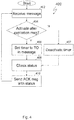
- Fig. 4 illustrates a flowchart 400 showing the processing performed by the wayside interface unit 152 according to one embodiment of the invention.
- the process starts with the receipt of a message from a train at step 402.
- the wayside interface unit determines whether the message is an activate after expiration message at step 404. If so, the wayside interface unit sets the timer to the TO value contained in the message at step 406 (the timer is actually being reset if the train had previously sent a message .
- the wayside interface unit 152 will maintain separate timers for each train (the maintain session and activate after expiration messages from the processor 110 of the onboard equipment 101 will include a train identifier in each message, and the wayside interface unit will assign a timer to a train upon receipt of the first message from the train), and the timer that will be set will be the timer correspond to the train ID in the message (if the timer was not previously active, this step includes activation of the timer).
- Multiple timers may be used because it is possible that multiple trains (e.g., trains coming in opposite directions) will be approaching the crossing from opposite directions, and the wayside interface unit 152 may be configured to activate the crossing warning system 150 upon the expiration of any timer.
- the wayside interface unit 152 deactivates the timer at step 407. This is done to handle the case where a train slows dramatically or stops after having previously sent an "activate after expiration" message as discussed above.
- the status of the wayside equipment 102 is checked at step 408 and an ACK message including the status is transmitted at step 410. Step 402 is then repeated when the next message is received.
- the wayside interface unit 152 may be configured such that the expiration of a timer generates an interrupt, and an interrupt service routine in the wayside interface unit 152 then triggers an output that activates the wayside warning system 150.
- this functionality may be implemented as a polled function rather than an interrupt-drive function.
- the timers may be implemented in hardware forming part of the warning system 150, and wayside interface unit 152 may write values to the hardware timers and activate, reset and deactivate the timers as discussed above. In this way, if the wayside interface unit 152 fails after initiating a timer, the timer will continue counting down and activate the warning system 150. Still other arrangement may be used in other embodiments.
- Figs. 3 and 4 discuss activation of the crossing warning system 150.
- the warning system 150 must deactivate at some point. In some embodiments, this will be triggered by an island circuit.
- An "island” is a term of art used in the railroad industry to refer to an area of track that more or less intersects a roadway and, sometimes, pedestrian walkways alongside the road (it is referred to as an island because in many instances this section of roadway is raised relative to other sections and thus appears as an island when the lower lying areas of road become submerged during a rainstorm).
- An "island circuit” is a track occupancy circuit that is configured to detect the presence of a train in the island.
- the wayside interface unit may, once it has commanded the warning system 150 to activate, monitor the island circuit to determine when a train both enters and clears the island and, upon the train clearing the island, deactivate the warning system 150 (assuming no other timer has or is about to expire).
- the processor 110 onboard a train can be configured to transmit a message when the end of the train has cleared the island.
- the ability to determine when an end of the train has cleared an island can be accomplished in any number of ways, including through use of the techniques disclosed in, e.g., U.S. Patent Nos. 6,915,191 and/or 6,081,769.
- the "activate after expiration" message includes an express time period (referred to as the timeout) after which the crossing should activate. Including the time expressly in the message provides for the ability to change the time to account for train accelerations and declerations as discussed above.
- the time period can be implied.
- the activate after expiration message may not expressly include any time period, and the wayside equipment may treat the message as including an implied timeout period (in other words, the message type itself indicates the timeout period). In such a system, the "activate after expiration" message need only be sent and acknowledged once.
- the train may not have a mechanism to accelerate the activation of the warning system to accommodate any train acceleration so the constant warning and timeout periods must be chosen with this in mind, and likewise the train may not have a mechanism to delay a previously-started timer at the wayside unit to account for decelerations of the train.
- such a provision could be realized by providing for a reset message to be sent from the train when a change in the timeout value is desirable due to a train acceleration or deceleration.
- the equipment described herein may be used as a backup system when conventional wayside constant warning time predictor equipment fails, or may be used together with the wayside constant warning time predictor equipment to provide redundant operation.
- DAX is an acronym that signifies downstream adjacent crossing
- DAXing is generally used to refer to the process of using a constant warning time predictor circuit at one location to trigger the activation of crossing warning system at crossings downstream of the crossing with the wayside constant warning time predictor equipment.
- Table 1 An exemplary sequence in a hypothetical situation in which a train approaches three closely spaced crossings is illustrated in Table 1 below: Table 1 Train Crossing A Crossing B Crossing C 3000 it from train at start 4000 it from train at start 4300 it from train at start Train comes within range of Crossing A Train sends session request message to Crossing A sends ACK for session Crossing A request message Train sends maintain session messages with crossing A Crossing A ACKs maintain session messages from train Train comes within range of Crossing B Train sends session request message to Crossing B Crossing B sends ACK for session request message Train sends maintain session messages with crossing B Crossing B ACKs maintain session messages from train Train comes within range of Crossing C Crossing C sends ACK for session request message Train sends session request message to Crossing C Crossing C ACKs maintain session messages from train Train reaches activation threshold for crossing A and sends activate after expiration message w/ 10s TO to Crossing A Crossing A sets timer to 10s and sends ACK Train sends activate after expiration message w/ 9
- a timer expires and crossing A warning system activates Train sends activate after expiration message w/2s TO to crossing B
- Crossing B sets timer to 2s and sends ACK
- Train sends activate after expiration message w/4s TO to Crossing C sets timer to 4s and sends ACK crossing C ... ... ... ... ... Crossing B timer expires and crossing B warning system activates Train sends activate after expiration message w/2s TO to crossing C
- Crossing C sets timer to 2s and sends ACK ... ... ... ... Crossing C timer expires and crossing C warning system activates
Landscapes
- Engineering & Computer Science (AREA)
- Mechanical Engineering (AREA)
- Train Traffic Observation, Control, And Security (AREA)
Claims (7)
- Rechnergestütztes Verfahren zur Steuerung eines Bahnübergangs von einem Zug aus, wobei das Verfahren Folgendes umfasst:Bestimmen, durch einen in einem Zug befindlichen Prozessor, eines Orts und einer Geschwindigkeit des Zugs,Erhalten, durch den Prozessor, eines Ortes eines ersten Übergangs, dem sich der Zug annähert, aus einer Streckendatenbank, die mit dem Rechner in einer Kommunikationsverbindung steht,Durchführen einer Bestimmung, durch den Prozessor, dass eine geschätzte Zeitdauer für die Ankunft des Zugs an dem ersten Übergang unter einem Schwellenwert liegt, wobei der Schwellenwert zumindest teilweise auf einer konstanten Warnzeitdauer basiert, wobei die konstante Warnzeitdauer eine Zeitdauer vor der Ankunft des Zugs an dem ersten Übergang, in der das Bahnübergangswarnsystem aktiviert werden sollte,als Antwort auf die Bestimmung Übertragen einer Nachricht durch den Prozessor an eine erste streckenseitige Einrichtung, wobei die Nachricht eine Pufferzeitdauer anzeigt, in der der Zug sich innerhalb der konstanten Warnzeitdauer des Erreichens des ersten Übergangs befinden wird, wobei die erste streckenseitige Einrichtung das Bahnübergangswarnsystem bei Ablauf der Pufferzeitdauer aktiviert, undVerifizieren, durch den Prozessor, dass eine Bestätigung der Nachricht von der ersten streckenseitigen Einrichtung empfangen wird.
- Verfahren nach Anspruch 1, wobei der Prozessor ferner dazu ausgebildet ist, den Zug anzuhalten, wenn eine Bestätigung der Nachricht nicht empfangen wird.
- Verfahren nach Anspruch 1, wobei der Prozessor ferner dazu ausgebildet ist, die konstante Warnzeit für den ersten Übergang aus der Streckendatenbank abzurufen.
- Verfahren nach Anspruch 1, wobei der Prozessor ferner dazu ausgebildet ist, mehrere Nachrichten, die Pufferzeiten anzeigen, an die erste streckenseitige Einrichtung zu senden, während der Zug sich der ersten streckenseitigen Einrichtung nähert, wobei die Pufferzeiten sich in jeder Nachricht in Abhängigkeit von einer Geschwindigkeit und einem Ort des Zugs ändern.
- Verfahren nach Anspruch 1, wobei der Prozessor dazu ausgebildet ist, eine zweite Nachricht, die eine zweite Pufferzeit enthält, bevor der Zug einen ersten Übergang erreicht, der der ersten streckenseitigen Einrichtung zugeordnet ist, an eine zweite streckenseitige Einrichtung zu senden.
- Verfahren nach Anspruch 1, wobei der Prozessor ferner dazu ausgebildet ist, zu erkennen, wenn ein Ende des Zugs den ersten Übergang passiert hat, und eine Nachricht an die erste streckenseitige Einrichtung zu senden, die anzeigt, dass das Ende des Zugs den ersten Übergang passiert hat.
- Verfahren nach Anspruch 1, wobei die Nachricht von dem Zug an die erste streckenseitige Einrichtung durch eine Zentralstation geleitet wird, die sich außerhalb des Zugs und von der streckenseitigen Einrichtung entfernt befindet.
Applications Claiming Priority (2)
| Application Number | Priority Date | Filing Date | Title |
|---|---|---|---|
| US13/078,464 US8668169B2 (en) | 2011-04-01 | 2011-04-01 | Communications based crossing control for locomotive-centric systems |
| EP12161153.7A EP2505452B1 (de) | 2011-04-01 | 2012-03-26 | Kommunikation basierend auf der Kreuzungssteuerung für lokomotiv-zentrale Systeme |
Related Parent Applications (2)
| Application Number | Title | Priority Date | Filing Date |
|---|---|---|---|
| EP12161153.7A Division-Into EP2505452B1 (de) | 2011-04-01 | 2012-03-26 | Kommunikation basierend auf der Kreuzungssteuerung für lokomotiv-zentrale Systeme |
| EP12161153.7A Division EP2505452B1 (de) | 2011-04-01 | 2012-03-26 | Kommunikation basierend auf der Kreuzungssteuerung für lokomotiv-zentrale Systeme |
Publications (2)
| Publication Number | Publication Date |
|---|---|
| EP3521134A1 EP3521134A1 (de) | 2019-08-07 |
| EP3521134B1 true EP3521134B1 (de) | 2021-11-03 |
Family
ID=45936902
Family Applications (2)
| Application Number | Title | Priority Date | Filing Date |
|---|---|---|---|
| EP12161153.7A Active EP2505452B1 (de) | 2011-04-01 | 2012-03-26 | Kommunikation basierend auf der Kreuzungssteuerung für lokomotiv-zentrale Systeme |
| EP19162567.2A Active EP3521134B1 (de) | 2011-04-01 | 2012-03-26 | Methode zur steuerung eines bahnübergangs vom zug aus |
Family Applications Before (1)
| Application Number | Title | Priority Date | Filing Date |
|---|---|---|---|
| EP12161153.7A Active EP2505452B1 (de) | 2011-04-01 | 2012-03-26 | Kommunikation basierend auf der Kreuzungssteuerung für lokomotiv-zentrale Systeme |
Country Status (5)
| Country | Link |
|---|---|
| US (1) | US8668169B2 (de) |
| EP (2) | EP2505452B1 (de) |
| CA (1) | CA2771905C (de) |
| ES (1) | ES2906318T3 (de) |
| MX (1) | MX2012003583A (de) |
Families Citing this family (24)
| Publication number | Priority date | Publication date | Assignee | Title |
|---|---|---|---|---|
| US8668169B2 (en) * | 2011-04-01 | 2014-03-11 | Siemens Rail Automation Corporation | Communications based crossing control for locomotive-centric systems |
| US8833703B2 (en) * | 2011-07-15 | 2014-09-16 | General Electric Company | Systems and method for a crossing equipment controller |
| US8725405B2 (en) * | 2012-04-13 | 2014-05-13 | General Electric Company | Methods and system for crossing prediction |
| US9166952B2 (en) * | 2012-10-15 | 2015-10-20 | Thales Canada Inc | Security device bank and a system including the and SD security device bank |
| US9340220B2 (en) * | 2013-05-23 | 2016-05-17 | Alstom Transport Technologies | Systems and methods for management of crossings near stations |
| US9150229B2 (en) * | 2013-06-05 | 2015-10-06 | General Electric Company | Systems and method for controlling warnings at vehicle crossings |
| JP6284723B2 (ja) * | 2013-08-27 | 2018-02-28 | 大同信号株式会社 | 列車位置の補正方法 |
| US11021178B2 (en) * | 2015-10-24 | 2021-06-01 | Nabil N. Ghaly | Method and apparatus for autonomous train control system |
| US9925994B2 (en) | 2015-10-27 | 2018-03-27 | Siemens Industry, Inc. | Cutout systems and methods |
| US20230339526A1 (en) * | 2016-01-21 | 2023-10-26 | Transportation Ip Holdings, Llc | Intersection management system |
| US12441307B2 (en) | 2020-01-03 | 2025-10-14 | Xorail, Inc. | Obstruction detection system |
| US10382348B2 (en) * | 2016-11-23 | 2019-08-13 | General Motors Llc | Time ordered message serializer |
| WO2018232129A1 (en) * | 2017-06-15 | 2018-12-20 | Westinghouse Air Brake Technologies Corporation | Crossing warning adjustment system and method |
| US10773742B2 (en) * | 2017-09-13 | 2020-09-15 | Siemens Industry, Inc. | Advanced preemption using the wayside inspector and wireless magnetometer sensors |
| US10768001B2 (en) * | 2018-01-10 | 2020-09-08 | Ford Global Technologies, Llc | Methods and apparatus to facilitate mitigation of vehicle trapping on railroad crossings |
| US11827260B2 (en) * | 2018-03-06 | 2023-11-28 | Siemens Mobility, Inc. | Grade crossing control system |
| US11021180B2 (en) * | 2018-04-06 | 2021-06-01 | Siemens Mobility, Inc. | Railway road crossing warning system with sensing system electrically-decoupled from railroad track |
| AU2020377984A1 (en) | 2019-11-06 | 2022-05-12 | Humatics Corporation | Techniques and associated systems and methods for determining train motion characteristics |
| CN112572537A (zh) * | 2020-12-30 | 2021-03-30 | 卡斯柯信号有限公司 | 一种车地协同的列车运行控制系统及方法 |
| CN114492200B (zh) * | 2022-02-16 | 2025-04-04 | 北京京投信安科技发展有限公司 | 一种地铁运营应急预案信息化管理系统 |
| FR3144095A1 (fr) * | 2022-12-23 | 2024-06-28 | Société Nationale SNCF | Passage à niveau et procédé d’actionnement d’un tel passage à niveau. |
| WO2024242923A1 (en) * | 2023-05-25 | 2024-11-28 | Siemens Mobility, Inc. | Systems and methods for crossing control |
| US20250187496A1 (en) * | 2023-12-12 | 2025-06-12 | Siemens Mobility, Inc. | Grade crossing system including grade crossing predictor in electrified propulsion territory |
| US20250249941A1 (en) * | 2024-02-02 | 2025-08-07 | Robert Ho | Automated Warning System for Uncontrolled Railroad Crossings |
Family Cites Families (26)
| Publication number | Priority date | Publication date | Assignee | Title |
|---|---|---|---|---|
| US4711418A (en) | 1986-04-08 | 1987-12-08 | General Signal Corporation | Radio based railway signaling and traffic control system |
| US5098044A (en) | 1989-12-22 | 1992-03-24 | General Railway Signal Corporation | Highway crossing control system for railroads utilizing a communications link between the train locomotive and the crossing protection equipment |
| US5533695A (en) | 1994-08-19 | 1996-07-09 | Harmon Industries, Inc. | Incremental train control system |
| US5620155A (en) | 1995-03-23 | 1997-04-15 | Michalek; Jan K. | Railway train signalling system for remotely operating warning devices at crossings and for receiving warning device operational information |
| US5785283A (en) | 1996-11-25 | 1998-07-28 | Union Switch & Signal Inc. | System and method for communicating operational status of a railway wayside to a locomotive cab |
| US5978718A (en) | 1997-07-22 | 1999-11-02 | Westinghouse Air Brake Company | Rail vision system |
| US6081769A (en) | 1998-02-23 | 2000-06-27 | Wabtec Corporation | Method and apparatus for determining the overall length of a train |
| US6865454B2 (en) | 2002-07-02 | 2005-03-08 | Quantum Engineering Inc. | Train control system and method of controlling a train or trains |
| US6996461B2 (en) | 2002-10-10 | 2006-02-07 | Quantum Engineering, Inc. | Method and system for ensuring that a train does not pass an improperly configured device |
| US6845953B2 (en) | 2002-10-10 | 2005-01-25 | Quantum Engineering, Inc. | Method and system for checking track integrity |
| US6915191B2 (en) | 2003-05-19 | 2005-07-05 | Quantum Engineering, Inc. | Method and system for detecting when an end of train has passed a point |
| US7729819B2 (en) * | 2004-05-08 | 2010-06-01 | Konkan Railway Corporation Ltd. | Track identification system |
| US20060015224A1 (en) | 2004-07-15 | 2006-01-19 | Hilleary Thomas N | Systems and methods for delivery of railroad crossing and wayside equipment operational data |
| US20060180712A1 (en) * | 2005-02-14 | 2006-08-17 | Hill James L | Advance warning system for railroad crossing |
| US7575202B2 (en) * | 2005-10-14 | 2009-08-18 | Safetran Systems Corporation | Apparatus and methods for providing relatively constant warning time at highway-rail crossings |
| US7593963B2 (en) | 2005-11-29 | 2009-09-22 | General Electric Company | Method and apparatus for remote detection and control of data recording systems on moving systems |
| DE102006040540A1 (de) * | 2006-08-30 | 2008-03-13 | Deutsches Zentrum für Luft- und Raumfahrt e.V. | Einrichtung und Verfahren zum Erkennen des Zugschlusses eines schienengebundenen Fahrzeuges oder eines schienengebundenen Fahrzeugverbandes |
| US20080068164A1 (en) * | 2006-09-12 | 2008-03-20 | International Business Machines Corporation | System and method for sensing and controlling spacing between railroad trains |
| US8028961B2 (en) * | 2006-12-22 | 2011-10-04 | Central Signal, Llc | Vital solid state controller |
| US7731129B2 (en) * | 2007-06-25 | 2010-06-08 | General Electric Company | Methods and systems for variable rate communication timeout |
| US20090043435A1 (en) * | 2007-08-07 | 2009-02-12 | Quantum Engineering, Inc. | Methods and systems for making a gps signal vital |
| US7832691B2 (en) * | 2008-01-17 | 2010-11-16 | Lockheed Martin Corporation | System and method for train operation approaching grade crossings |
| US8090486B2 (en) * | 2008-01-17 | 2012-01-03 | Lockheed Martin Corporation | Message protocol for efficient transmission of vital directives on a guideway |
| US8500071B2 (en) * | 2009-10-27 | 2013-08-06 | Invensys Rail Corporation | Method and apparatus for bi-directional downstream adjacent crossing signaling |
| US8297558B2 (en) * | 2010-03-17 | 2012-10-30 | Safetran Systems Corporation | Crossing predictor with authorized track speed input |
| US8668169B2 (en) * | 2011-04-01 | 2014-03-11 | Siemens Rail Automation Corporation | Communications based crossing control for locomotive-centric systems |
-
2011
- 2011-04-01 US US13/078,464 patent/US8668169B2/en active Active
-
2012
- 2012-03-20 CA CA2771905A patent/CA2771905C/en active Active
- 2012-03-26 MX MX2012003583A patent/MX2012003583A/es active IP Right Grant
- 2012-03-26 ES ES19162567T patent/ES2906318T3/es active Active
- 2012-03-26 EP EP12161153.7A patent/EP2505452B1/de active Active
- 2012-03-26 EP EP19162567.2A patent/EP3521134B1/de active Active
Also Published As
| Publication number | Publication date |
|---|---|
| ES2906318T3 (es) | 2022-04-18 |
| MX2012003583A (es) | 2013-07-12 |
| EP2505452A3 (de) | 2017-09-06 |
| EP2505452A2 (de) | 2012-10-03 |
| CA2771905A1 (en) | 2012-10-01 |
| EP2505452B1 (de) | 2019-11-27 |
| EP3521134A1 (de) | 2019-08-07 |
| US8668169B2 (en) | 2014-03-11 |
| US20120248261A1 (en) | 2012-10-04 |
| CA2771905C (en) | 2019-04-09 |
Similar Documents
| Publication | Publication Date | Title |
|---|---|---|
| EP2505452B1 (de) | Kommunikation basierend auf der Kreuzungssteuerung für lokomotiv-zentrale Systeme | |
| CA2501263C (en) | Method and system for ensuring that a train does not pass an improperly configured device | |
| CA2518911C (en) | Lifting restrictive signaling in a block | |
| AU2014100572A4 (en) | Systems and methods for controlling warnings at vehicle crossings | |
| US9126609B2 (en) | Systems and methods for controlling warnings at vehicle crossings | |
| CN107745729B (zh) | 一种有轨电车自动驾驶系统 | |
| US11124213B2 (en) | Method for securing a level crossing, and stationary control device for a train control system | |
| JP6914354B2 (ja) | 鉄道踏切状況情報を自動運転車へ供給するシステムおよび方法 | |
| US12012135B2 (en) | Vehicle warning system | |
| US10449983B2 (en) | Method for commanding a railway level crossing protection system | |
| US20040049327A1 (en) | Radio based automatic train control system using universal code | |
| CN117775082A (zh) | 一种基于二次雷达的轨道交通后备降级运行系统及方法 | |
| CA3218746C (en) | TRAIN CONTROL SYSTEMS INCLUDING HAZARD MANAGEMENT AND RELATED METHODS | |
| RU126306U1 (ru) | Система управления движением поездов при диспетчерской централизации | |
| KR102356865B1 (ko) | 단선 버스전용차로 운영 시스템 | |
| RU2529561C1 (ru) | Автоматическая система принудительной остановки поездов и маневровых составов у путевых упоров при движении на тупиковых путях станции | |
| US11775278B1 (en) | Systems and methods for automated traffic control update | |
| CN120902799A (zh) | 运行基于无线电的列车控制系统的方法和用于基于无线电的列车控制系统的线路调度中心 | |
| WO2018232129A1 (en) | Crossing warning adjustment system and method | |
| JP2024165849A (ja) | 列車接近報知システム | |
| WO2024242923A1 (en) | Systems and methods for crossing control |
Legal Events
| Date | Code | Title | Description |
|---|---|---|---|
| PUAI | Public reference made under article 153(3) epc to a published international application that has entered the european phase |
Free format text: ORIGINAL CODE: 0009012 |
|
| STAA | Information on the status of an ep patent application or granted ep patent |
Free format text: STATUS: THE APPLICATION HAS BEEN PUBLISHED |
|
| AC | Divisional application: reference to earlier application |
Ref document number: 2505452 Country of ref document: EP Kind code of ref document: P |
|
| AK | Designated contracting states |
Kind code of ref document: A1 Designated state(s): AL AT BE BG CH CY CZ DE DK EE ES FI FR GB GR HR HU IE IS IT LI LT LU LV MC MK MT NL NO PL PT RO RS SE SI SK SM TR |
|
| STAA | Information on the status of an ep patent application or granted ep patent |
Free format text: STATUS: REQUEST FOR EXAMINATION WAS MADE |
|
| RAP1 | Party data changed (applicant data changed or rights of an application transferred) |
Owner name: SIEMENS MOBILITY, INC. |
|
| 17P | Request for examination filed |
Effective date: 20200206 |
|
| RBV | Designated contracting states (corrected) |
Designated state(s): AL AT BE BG CH CY CZ DE DK EE ES FI FR GB GR HR HU IE IS IT LI LT LU LV MC MK MT NL NO PL PT RO RS SE SI SK SM TR |
|
| GRAP | Despatch of communication of intention to grant a patent |
Free format text: ORIGINAL CODE: EPIDOSNIGR1 |
|
| STAA | Information on the status of an ep patent application or granted ep patent |
Free format text: STATUS: GRANT OF PATENT IS INTENDED |
|
| INTG | Intention to grant announced |
Effective date: 20210705 |
|
| GRAS | Grant fee paid |
Free format text: ORIGINAL CODE: EPIDOSNIGR3 |
|
| GRAA | (expected) grant |
Free format text: ORIGINAL CODE: 0009210 |
|
| STAA | Information on the status of an ep patent application or granted ep patent |
Free format text: STATUS: THE PATENT HAS BEEN GRANTED |
|
| AC | Divisional application: reference to earlier application |
Ref document number: 2505452 Country of ref document: EP Kind code of ref document: P |
|
| AK | Designated contracting states |
Kind code of ref document: B1 Designated state(s): AL AT BE BG CH CY CZ DE DK EE ES FI FR GB GR HR HU IE IS IT LI LT LU LV MC MK MT NL NO PL PT RO RS SE SI SK SM TR |
|
| REG | Reference to a national code |
Ref country code: GB Ref legal event code: FG4D |
|
| REG | Reference to a national code |
Ref country code: AT Ref legal event code: REF Ref document number: 1443717 Country of ref document: AT Kind code of ref document: T Effective date: 20211115 Ref country code: CH Ref legal event code: EP |
|
| REG | Reference to a national code |
Ref country code: DE Ref legal event code: R096 Ref document number: 602012077109 Country of ref document: DE |
|
| REG | Reference to a national code |
Ref country code: IE Ref legal event code: FG4D |
|
| RAP4 | Party data changed (patent owner data changed or rights of a patent transferred) |
Owner name: SIEMENS MOBILITY, INC. |
|
| REG | Reference to a national code |
Ref country code: LT Ref legal event code: MG9D |
|
| REG | Reference to a national code |
Ref country code: NL Ref legal event code: MP Effective date: 20211103 |
|
| REG | Reference to a national code |
Ref country code: ES Ref legal event code: FG2A Ref document number: 2906318 Country of ref document: ES Kind code of ref document: T3 Effective date: 20220418 |
|
| PG25 | Lapsed in a contracting state [announced via postgrant information from national office to epo] |
Ref country code: RS Free format text: LAPSE BECAUSE OF FAILURE TO SUBMIT A TRANSLATION OF THE DESCRIPTION OR TO PAY THE FEE WITHIN THE PRESCRIBED TIME-LIMIT Effective date: 20211103 Ref country code: LT Free format text: LAPSE BECAUSE OF FAILURE TO SUBMIT A TRANSLATION OF THE DESCRIPTION OR TO PAY THE FEE WITHIN THE PRESCRIBED TIME-LIMIT Effective date: 20211103 Ref country code: FI Free format text: LAPSE BECAUSE OF FAILURE TO SUBMIT A TRANSLATION OF THE DESCRIPTION OR TO PAY THE FEE WITHIN THE PRESCRIBED TIME-LIMIT Effective date: 20211103 Ref country code: BG Free format text: LAPSE BECAUSE OF FAILURE TO SUBMIT A TRANSLATION OF THE DESCRIPTION OR TO PAY THE FEE WITHIN THE PRESCRIBED TIME-LIMIT Effective date: 20220203 |
|
| PG25 | Lapsed in a contracting state [announced via postgrant information from national office to epo] |
Ref country code: IS Free format text: LAPSE BECAUSE OF FAILURE TO SUBMIT A TRANSLATION OF THE DESCRIPTION OR TO PAY THE FEE WITHIN THE PRESCRIBED TIME-LIMIT Effective date: 20220303 Ref country code: SE Free format text: LAPSE BECAUSE OF FAILURE TO SUBMIT A TRANSLATION OF THE DESCRIPTION OR TO PAY THE FEE WITHIN THE PRESCRIBED TIME-LIMIT Effective date: 20211103 Ref country code: PT Free format text: LAPSE BECAUSE OF FAILURE TO SUBMIT A TRANSLATION OF THE DESCRIPTION OR TO PAY THE FEE WITHIN THE PRESCRIBED TIME-LIMIT Effective date: 20220303 Ref country code: PL Free format text: LAPSE BECAUSE OF FAILURE TO SUBMIT A TRANSLATION OF THE DESCRIPTION OR TO PAY THE FEE WITHIN THE PRESCRIBED TIME-LIMIT Effective date: 20211103 Ref country code: NO Free format text: LAPSE BECAUSE OF FAILURE TO SUBMIT A TRANSLATION OF THE DESCRIPTION OR TO PAY THE FEE WITHIN THE PRESCRIBED TIME-LIMIT Effective date: 20220203 Ref country code: NL Free format text: LAPSE BECAUSE OF FAILURE TO SUBMIT A TRANSLATION OF THE DESCRIPTION OR TO PAY THE FEE WITHIN THE PRESCRIBED TIME-LIMIT Effective date: 20211103 Ref country code: LV Free format text: LAPSE BECAUSE OF FAILURE TO SUBMIT A TRANSLATION OF THE DESCRIPTION OR TO PAY THE FEE WITHIN THE PRESCRIBED TIME-LIMIT Effective date: 20211103 Ref country code: HR Free format text: LAPSE BECAUSE OF FAILURE TO SUBMIT A TRANSLATION OF THE DESCRIPTION OR TO PAY THE FEE WITHIN THE PRESCRIBED TIME-LIMIT Effective date: 20211103 Ref country code: GR Free format text: LAPSE BECAUSE OF FAILURE TO SUBMIT A TRANSLATION OF THE DESCRIPTION OR TO PAY THE FEE WITHIN THE PRESCRIBED TIME-LIMIT Effective date: 20220204 |
|
| PG25 | Lapsed in a contracting state [announced via postgrant information from national office to epo] |
Ref country code: SM Free format text: LAPSE BECAUSE OF FAILURE TO SUBMIT A TRANSLATION OF THE DESCRIPTION OR TO PAY THE FEE WITHIN THE PRESCRIBED TIME-LIMIT Effective date: 20211103 Ref country code: SK Free format text: LAPSE BECAUSE OF FAILURE TO SUBMIT A TRANSLATION OF THE DESCRIPTION OR TO PAY THE FEE WITHIN THE PRESCRIBED TIME-LIMIT Effective date: 20211103 Ref country code: RO Free format text: LAPSE BECAUSE OF FAILURE TO SUBMIT A TRANSLATION OF THE DESCRIPTION OR TO PAY THE FEE WITHIN THE PRESCRIBED TIME-LIMIT Effective date: 20211103 Ref country code: EE Free format text: LAPSE BECAUSE OF FAILURE TO SUBMIT A TRANSLATION OF THE DESCRIPTION OR TO PAY THE FEE WITHIN THE PRESCRIBED TIME-LIMIT Effective date: 20211103 Ref country code: DK Free format text: LAPSE BECAUSE OF FAILURE TO SUBMIT A TRANSLATION OF THE DESCRIPTION OR TO PAY THE FEE WITHIN THE PRESCRIBED TIME-LIMIT Effective date: 20211103 Ref country code: CZ Free format text: LAPSE BECAUSE OF FAILURE TO SUBMIT A TRANSLATION OF THE DESCRIPTION OR TO PAY THE FEE WITHIN THE PRESCRIBED TIME-LIMIT Effective date: 20211103 |
|
| REG | Reference to a national code |
Ref country code: DE Ref legal event code: R097 Ref document number: 602012077109 Country of ref document: DE |
|
| PLBE | No opposition filed within time limit |
Free format text: ORIGINAL CODE: 0009261 |
|
| STAA | Information on the status of an ep patent application or granted ep patent |
Free format text: STATUS: NO OPPOSITION FILED WITHIN TIME LIMIT |
|
| 26N | No opposition filed |
Effective date: 20220804 |
|
| PG25 | Lapsed in a contracting state [announced via postgrant information from national office to epo] |
Ref country code: MC Free format text: LAPSE BECAUSE OF FAILURE TO SUBMIT A TRANSLATION OF THE DESCRIPTION OR TO PAY THE FEE WITHIN THE PRESCRIBED TIME-LIMIT Effective date: 20211103 Ref country code: AL Free format text: LAPSE BECAUSE OF FAILURE TO SUBMIT A TRANSLATION OF THE DESCRIPTION OR TO PAY THE FEE WITHIN THE PRESCRIBED TIME-LIMIT Effective date: 20211103 |
|
| REG | Reference to a national code |
Ref country code: CH Ref legal event code: PL |
|
| PG25 | Lapsed in a contracting state [announced via postgrant information from national office to epo] |
Ref country code: SI Free format text: LAPSE BECAUSE OF FAILURE TO SUBMIT A TRANSLATION OF THE DESCRIPTION OR TO PAY THE FEE WITHIN THE PRESCRIBED TIME-LIMIT Effective date: 20211103 |
|
| REG | Reference to a national code |
Ref country code: BE Ref legal event code: MM Effective date: 20220331 |
|
| PG25 | Lapsed in a contracting state [announced via postgrant information from national office to epo] |
Ref country code: LU Free format text: LAPSE BECAUSE OF NON-PAYMENT OF DUE FEES Effective date: 20220326 Ref country code: LI Free format text: LAPSE BECAUSE OF NON-PAYMENT OF DUE FEES Effective date: 20220331 Ref country code: IE Free format text: LAPSE BECAUSE OF NON-PAYMENT OF DUE FEES Effective date: 20220326 Ref country code: FR Free format text: LAPSE BECAUSE OF NON-PAYMENT OF DUE FEES Effective date: 20220331 Ref country code: CH Free format text: LAPSE BECAUSE OF NON-PAYMENT OF DUE FEES Effective date: 20220331 |
|
| PG25 | Lapsed in a contracting state [announced via postgrant information from national office to epo] |
Ref country code: BE Free format text: LAPSE BECAUSE OF NON-PAYMENT OF DUE FEES Effective date: 20220331 |
|
| PG25 | Lapsed in a contracting state [announced via postgrant information from national office to epo] |
Ref country code: IT Free format text: LAPSE BECAUSE OF FAILURE TO SUBMIT A TRANSLATION OF THE DESCRIPTION OR TO PAY THE FEE WITHIN THE PRESCRIBED TIME-LIMIT Effective date: 20211103 |
|
| PG25 | Lapsed in a contracting state [announced via postgrant information from national office to epo] |
Ref country code: MK Free format text: LAPSE BECAUSE OF FAILURE TO SUBMIT A TRANSLATION OF THE DESCRIPTION OR TO PAY THE FEE WITHIN THE PRESCRIBED TIME-LIMIT Effective date: 20211103 Ref country code: CY Free format text: LAPSE BECAUSE OF FAILURE TO SUBMIT A TRANSLATION OF THE DESCRIPTION OR TO PAY THE FEE WITHIN THE PRESCRIBED TIME-LIMIT Effective date: 20211103 |
|
| PG25 | Lapsed in a contracting state [announced via postgrant information from national office to epo] |
Ref country code: HU Free format text: LAPSE BECAUSE OF FAILURE TO SUBMIT A TRANSLATION OF THE DESCRIPTION OR TO PAY THE FEE WITHIN THE PRESCRIBED TIME-LIMIT; INVALID AB INITIO Effective date: 20120326 |
|
| PG25 | Lapsed in a contracting state [announced via postgrant information from national office to epo] |
Ref country code: TR Free format text: LAPSE BECAUSE OF FAILURE TO SUBMIT A TRANSLATION OF THE DESCRIPTION OR TO PAY THE FEE WITHIN THE PRESCRIBED TIME-LIMIT Effective date: 20211103 |
|
| PG25 | Lapsed in a contracting state [announced via postgrant information from national office to epo] |
Ref country code: MT Free format text: LAPSE BECAUSE OF FAILURE TO SUBMIT A TRANSLATION OF THE DESCRIPTION OR TO PAY THE FEE WITHIN THE PRESCRIBED TIME-LIMIT Effective date: 20211103 |
|
| PGFP | Annual fee paid to national office [announced via postgrant information from national office to epo] |
Ref country code: DE Payment date: 20250520 Year of fee payment: 14 |
|
| PGFP | Annual fee paid to national office [announced via postgrant information from national office to epo] |
Ref country code: GB Payment date: 20250403 Year of fee payment: 14 Ref country code: ES Payment date: 20250620 Year of fee payment: 14 |
|
| PGFP | Annual fee paid to national office [announced via postgrant information from national office to epo] |
Ref country code: AT Payment date: 20260206 Year of fee payment: 15 |