EP3521130A1 - Backing device, axlebox, vehicle and methods for mounting and dismounting such a backing device - Google Patents
Backing device, axlebox, vehicle and methods for mounting and dismounting such a backing device Download PDFInfo
- Publication number
- EP3521130A1 EP3521130A1 EP19155117.5A EP19155117A EP3521130A1 EP 3521130 A1 EP3521130 A1 EP 3521130A1 EP 19155117 A EP19155117 A EP 19155117A EP 3521130 A1 EP3521130 A1 EP 3521130A1
- Authority
- EP
- European Patent Office
- Prior art keywords
- backing device
- axle
- inner ring
- axlebox
- ring
- Prior art date
- Legal status (The legal status is an assumption and is not a legal conclusion. Google has not performed a legal analysis and makes no representation as to the accuracy of the status listed.)
- Withdrawn
Links
Images


Classifications
-
- B—PERFORMING OPERATIONS; TRANSPORTING
- B60—VEHICLES IN GENERAL
- B60B—VEHICLE WHEELS; CASTORS; AXLES FOR WHEELS OR CASTORS; INCREASING WHEEL ADHESION
- B60B27/00—Hubs
- B60B27/0078—Hubs characterised by the fixation of bearings
-
- B—PERFORMING OPERATIONS; TRANSPORTING
- B61—RAILWAYS
- B61F—RAIL VEHICLE SUSPENSIONS, e.g. UNDERFRAMES, BOGIES OR ARRANGEMENTS OF WHEEL AXLES; RAIL VEHICLES FOR USE ON TRACKS OF DIFFERENT WIDTH; PREVENTING DERAILING OF RAIL VEHICLES; WHEEL GUARDS, OBSTRUCTION REMOVERS OR THE LIKE FOR RAIL VEHICLES
- B61F15/00—Axle-boxes
- B61F15/20—Details
-
- B—PERFORMING OPERATIONS; TRANSPORTING
- B61—RAILWAYS
- B61F—RAIL VEHICLE SUSPENSIONS, e.g. UNDERFRAMES, BOGIES OR ARRANGEMENTS OF WHEEL AXLES; RAIL VEHICLES FOR USE ON TRACKS OF DIFFERENT WIDTH; PREVENTING DERAILING OF RAIL VEHICLES; WHEEL GUARDS, OBSTRUCTION REMOVERS OR THE LIKE FOR RAIL VEHICLES
- B61F5/00—Constructional details of bogies; Connections between bogies and vehicle underframes; Arrangements or devices for adjusting or allowing self-adjustment of wheel axles or bogies when rounding curves
- B61F5/26—Mounting or securing axle-boxes in vehicle or bogie underframes
- B61F5/30—Axle-boxes mounted for movement under spring control in vehicle or bogie underframes
- B61F5/305—Axle-boxes mounted for movement under spring control in vehicle or bogie underframes incorporating rubber springs
-
- F—MECHANICAL ENGINEERING; LIGHTING; HEATING; WEAPONS; BLASTING
- F16—ENGINEERING ELEMENTS AND UNITS; GENERAL MEASURES FOR PRODUCING AND MAINTAINING EFFECTIVE FUNCTIONING OF MACHINES OR INSTALLATIONS; THERMAL INSULATION IN GENERAL
- F16C—SHAFTS; FLEXIBLE SHAFTS; ELEMENTS OR CRANKSHAFT MECHANISMS; ROTARY BODIES OTHER THAN GEARING ELEMENTS; BEARINGS
- F16C35/00—Rigid support of bearing units; Housings, e.g. caps, covers
- F16C35/04—Rigid support of bearing units; Housings, e.g. caps, covers in the case of ball or roller bearings
- F16C35/06—Mounting or dismounting of ball or roller bearings; Fixing them onto shaft or in housing
- F16C35/062—Dismounting of ball or roller bearings
-
- F—MECHANICAL ENGINEERING; LIGHTING; HEATING; WEAPONS; BLASTING
- F16—ENGINEERING ELEMENTS AND UNITS; GENERAL MEASURES FOR PRODUCING AND MAINTAINING EFFECTIVE FUNCTIONING OF MACHINES OR INSTALLATIONS; THERMAL INSULATION IN GENERAL
- F16C—SHAFTS; FLEXIBLE SHAFTS; ELEMENTS OR CRANKSHAFT MECHANISMS; ROTARY BODIES OTHER THAN GEARING ELEMENTS; BEARINGS
- F16C35/00—Rigid support of bearing units; Housings, e.g. caps, covers
- F16C35/04—Rigid support of bearing units; Housings, e.g. caps, covers in the case of ball or roller bearings
- F16C35/06—Mounting or dismounting of ball or roller bearings; Fixing them onto shaft or in housing
- F16C35/063—Fixing them on the shaft
-
- B—PERFORMING OPERATIONS; TRANSPORTING
- B60—VEHICLES IN GENERAL
- B60B—VEHICLE WHEELS; CASTORS; AXLES FOR WHEELS OR CASTORS; INCREASING WHEEL ADHESION
- B60B2320/00—Manufacturing or maintenance operations
- B60B2320/10—Assembling; disassembling
-
- F—MECHANICAL ENGINEERING; LIGHTING; HEATING; WEAPONS; BLASTING
- F16—ENGINEERING ELEMENTS AND UNITS; GENERAL MEASURES FOR PRODUCING AND MAINTAINING EFFECTIVE FUNCTIONING OF MACHINES OR INSTALLATIONS; THERMAL INSULATION IN GENERAL
- F16C—SHAFTS; FLEXIBLE SHAFTS; ELEMENTS OR CRANKSHAFT MECHANISMS; ROTARY BODIES OTHER THAN GEARING ELEMENTS; BEARINGS
- F16C19/00—Bearings with rolling contact, for exclusively rotary movement
- F16C19/22—Bearings with rolling contact, for exclusively rotary movement with bearing rollers essentially of the same size in one or more circular rows, e.g. needle bearings
- F16C19/24—Bearings with rolling contact, for exclusively rotary movement with bearing rollers essentially of the same size in one or more circular rows, e.g. needle bearings for radial load mainly
- F16C19/26—Bearings with rolling contact, for exclusively rotary movement with bearing rollers essentially of the same size in one or more circular rows, e.g. needle bearings for radial load mainly with a single row of rollers
-
- F—MECHANICAL ENGINEERING; LIGHTING; HEATING; WEAPONS; BLASTING
- F16—ENGINEERING ELEMENTS AND UNITS; GENERAL MEASURES FOR PRODUCING AND MAINTAINING EFFECTIVE FUNCTIONING OF MACHINES OR INSTALLATIONS; THERMAL INSULATION IN GENERAL
- F16C—SHAFTS; FLEXIBLE SHAFTS; ELEMENTS OR CRANKSHAFT MECHANISMS; ROTARY BODIES OTHER THAN GEARING ELEMENTS; BEARINGS
- F16C19/00—Bearings with rolling contact, for exclusively rotary movement
- F16C19/54—Systems consisting of a plurality of bearings with rolling friction
-
- F—MECHANICAL ENGINEERING; LIGHTING; HEATING; WEAPONS; BLASTING
- F16—ENGINEERING ELEMENTS AND UNITS; GENERAL MEASURES FOR PRODUCING AND MAINTAINING EFFECTIVE FUNCTIONING OF MACHINES OR INSTALLATIONS; THERMAL INSULATION IN GENERAL
- F16C—SHAFTS; FLEXIBLE SHAFTS; ELEMENTS OR CRANKSHAFT MECHANISMS; ROTARY BODIES OTHER THAN GEARING ELEMENTS; BEARINGS
- F16C2226/00—Joining parts; Fastening; Assembling or mounting parts
- F16C2226/10—Force connections, e.g. clamping
- F16C2226/16—Force connections, e.g. clamping by wedge action, e.g. by tapered or conical parts
-
- F—MECHANICAL ENGINEERING; LIGHTING; HEATING; WEAPONS; BLASTING
- F16—ENGINEERING ELEMENTS AND UNITS; GENERAL MEASURES FOR PRODUCING AND MAINTAINING EFFECTIVE FUNCTIONING OF MACHINES OR INSTALLATIONS; THERMAL INSULATION IN GENERAL
- F16C—SHAFTS; FLEXIBLE SHAFTS; ELEMENTS OR CRANKSHAFT MECHANISMS; ROTARY BODIES OTHER THAN GEARING ELEMENTS; BEARINGS
- F16C2326/00—Articles relating to transporting
- F16C2326/10—Railway vehicles
-
- F—MECHANICAL ENGINEERING; LIGHTING; HEATING; WEAPONS; BLASTING
- F16—ENGINEERING ELEMENTS AND UNITS; GENERAL MEASURES FOR PRODUCING AND MAINTAINING EFFECTIVE FUNCTIONING OF MACHINES OR INSTALLATIONS; THERMAL INSULATION IN GENERAL
- F16C—SHAFTS; FLEXIBLE SHAFTS; ELEMENTS OR CRANKSHAFT MECHANISMS; ROTARY BODIES OTHER THAN GEARING ELEMENTS; BEARINGS
- F16C33/00—Parts of bearings; Special methods for making bearings or parts thereof
- F16C33/72—Sealings
- F16C33/76—Sealings of ball or roller bearings
- F16C33/80—Labyrinth sealings
-
- Y—GENERAL TAGGING OF NEW TECHNOLOGICAL DEVELOPMENTS; GENERAL TAGGING OF CROSS-SECTIONAL TECHNOLOGIES SPANNING OVER SEVERAL SECTIONS OF THE IPC; TECHNICAL SUBJECTS COVERED BY FORMER USPC CROSS-REFERENCE ART COLLECTIONS [XRACs] AND DIGESTS
- Y10—TECHNICAL SUBJECTS COVERED BY FORMER USPC
- Y10T—TECHNICAL SUBJECTS COVERED BY FORMER US CLASSIFICATION
- Y10T29/00—Metal working
- Y10T29/49—Method of mechanical manufacture
- Y10T29/49815—Disassembling
- Y10T29/49822—Disassembling by applying force
-
- Y—GENERAL TAGGING OF NEW TECHNOLOGICAL DEVELOPMENTS; GENERAL TAGGING OF CROSS-SECTIONAL TECHNOLOGIES SPANNING OVER SEVERAL SECTIONS OF THE IPC; TECHNICAL SUBJECTS COVERED BY FORMER USPC CROSS-REFERENCE ART COLLECTIONS [XRACs] AND DIGESTS
- Y10—TECHNICAL SUBJECTS COVERED BY FORMER USPC
- Y10T—TECHNICAL SUBJECTS COVERED BY FORMER US CLASSIFICATION
- Y10T29/00—Metal working
- Y10T29/49—Method of mechanical manufacture
- Y10T29/49826—Assembling or joining
- Y10T29/49863—Assembling or joining with prestressing of part
Definitions
- the invention concerns a backing device, adapted to equip an axlebox comprising a bearing unit and supporting an axle.
- the invention also concerns an axlebox comprising such a backing device and a vehicle comprising such an axlebox.
- the invention also concerns methods for mounting and dismounting such a backing device.
- Axleboxes mounted on railway vehicles, such as trains, passenger coaches and freight cars, are the linking design elements between a rotating wheelset and the quasi-static frame of a bogie.
- An axlebox comprises a housing receiving a bearing unit.
- an axlebox with a device for backing the bearing unit mounted on the axle.
- the backing device has an annular shape and is mounted around the axle, between the bearing unit and an abutment formed on the axle.
- the backing device performs a mechanical connection between the axle and the bearing unit.
- the abutment is designed with a vertical face and a round shape in connection with the diameter of the bearing unit, in order to avoid stress concentration.
- the backing device is designed to equally distribute the pressure coming from the bearing unit and axial forces to the abutment.
- the backing device is generally press fitted on the axle.
- the backing device associated with the axlebox housing or a rear cover has a special shape for ensuring sealing between the bearing unit and the external environment of the axlebox, in order to avoid grease contamination.
- the abutment In practice, the abutment must be designed with a sufficient mechanical strength to press the bearing unit with a suitable mounting force when the axlebox is mounted on the axle, then to support axial forces coming from curve and switch points when the vehicle is in service.
- an oversized diameter of the abutment would negatively impact the size of the equipment mounted between the two axleboxes. Indeed, the diameter of the equipment, including wheels, gearbox and brakes, must be larger than the centering diameter of the backing device to avoid mechanical interference during assembly.
- the diameter of the backing device is a compromise between the diameter of the bearing unit and the diameter of the equipment. It often results in an optimized design with potential weaknesses, namely surface deformation on the contact interface between the backing device and the axle, stress concentration on certain areas of the axle, insufficient mounting force of the bearing unit due to the deformation risk. Besides, on some axleboxes, equipment and wheels are oversized to allow their mounting on the axle.
- US-B-6 561 559 discloses several examples of backing devices, adapted to equip an axlebox comprising a bearing unit mounted on an axle.
- US-A-2005/0052043 discloses a backing ring that serves to back an antifriction bearing on the journal of a rail car axle.
- This backing ring includes an annular body that seats against a fillet located at the end of the journal and also a lip that projects over a larger dust guard diameter that is located on the axle immediately beyond the fillet.
- the backing ring further includes a bushing which fits between the lip and the dust guard diameter.
- the bushing has a tapered outside surface which bears against a tapered inside surface of the lip and a cylindrical inside surface which is against the dust guard diameter.
- the bushing is split axially.
- CN-U-202 867 585 discloses a backing ring adapted to equip an axlebox comprising a bearing unit, the backing ring device comprising an inner ring having an inner surface with frustoconical outer surface portions, and an outer ring having an inner surface with frustoconical inner surface portions facing the said frustoconical outer surface portions.
- the backing ring further comprises tightening screws which extend through holes formed in outer ring and which has a threaded portion inserted in a threaded bore formed in inner ring. When the tightening screws are tightened, the frustoconical surface portions of inner and outer rings are pressed against each other.
- the aim of the invention is to provide an improved backing device and an improved axlebox.
- the invention concerns a backing device adapted to equip an axlebox comprising a bearing unit and supporting an axle.
- the backing device comprises an inner ring (250) having an inner surface (51) and at least one outer surface (252); at least one outer ring having an inner surface (262) facing the outer surface (252) of the inner ring (250); and tightening means (180).
- the tightening means (280) are inserted inside the inner ring (250) and/or the outer ring (260).
- the tightening means (280) comprise at least one cavity (281) formed inside the inner ring (250) and a valve (282) inserted inside the inner ring (250) in fluid communication with the cavity (281); and wherein the tightening means (280), when actuated by filling the cavity or cavities (281) with a fluid (F1), press the outer surface (252) of the inner ring (250) and the inner surface (262) of the outer ring (260) against each other and narrow the inner surface (51) of the inner ring (250) by elastic deformation thereof.
- the backing device can be quickly and easily locked in position on the axle or unlocked from the axle. It is no more compulsory to provide the axle with an abutment for the backing device, so that machining of the axle is simplified. Axial pressure exerted on the inner ring of the backing device is reduced or even suppressed. Diameter of components mounted on the axle behind the backing device can be reduced. Size, weight and costs of the axle are reduced. Besides, the invention offers more possibilities for designing the sealing means positioned between the axlebox housing and the backing device.
- the invention also concerns an axlebox adapted to support an axle, wherein the axlebox comprises a bearing unit and a backing device as described above.
- axlebox may incorporate one or several of the features:
- the invention also concerns a vehicle equipped with at least one axlebox according to any of the previous embodiments.
- the invention also concerns a method for mounting a backing device on an axle, wherein the backing device is according to any of the previous embodiments, and wherein the method comprises the following steps:
- the invention also concerns a method for dismounting a backing device from an axle, wherein the backing device as described above and wherein the method comprises the following steps:
- FIG 1 shows a bogie 2, partly represented for simplification purpose, belonging to a railway vehicle 1.
- Bogie 2 comprises a frame 3, two wheelset 4 and four axleboxes 9. Only one wheelset 4 and one axlebox 9 are shown on figure 1 for simplification purpose.
- Wheelset 4 comprises two wheels 5 supported by an axle 6, which is hidden by frame 3 and one of the wheels 5.
- Axlebox 9 is mounted on the outer side of the wheel 5 and secured to frame 3.
- Figure 1 explains the context of the application but does not show the invention.
- FIG 2 shows a wheelset 4, a wheel 5, an axle 6 and suspension systems 7, together with an axlebox 10 according to the invention.
- axlebox 10 is different from axlebox 9 shown on figure 1 .
- Suspension systems 7 connect axlebox 10 to the frame, not shown, of a vehicle which is also according to the invention.
- Axlebox 10 is mounted on axle 6 on the inner side of the wheel 5.
- Axlebox 10 supports axle 6, which supports wheels 5.
- Wheels 5, axle 6 and axlebox box 10 are centered on a central axis X10.
- FIGS 3 to 4 show axlebox 10, which comprises a housing 20, a bearing unit 30 and a backing device 40 according to the invention.
- Housing 20 comprises an upper part 21 and a lower part 22. Housing 20 defines a cavity 23 receiving bearing unit 30 and a cavity 24 receiving backing device 40. Cavities 23 and 24 are centered on axis X10. Axlebox 10 comprises bolts 26 for fastening parts 21 and 22 together, once bearing unit 30 is mounted inside cavity 23.
- Bearing unit 30 comprises two rolling bearings mounted against each other on axle 6. Bearings are centered on axis X10. Each bearing comprises an inner ring 33 mounted on axle 6, an outer ring 34 fitted in cavity 23 of housing 20, and rolling elements 35 mounted between inner ring 33 and outer ring 34. Alternatively, bearing unit 30 may comprise a single bearing, of any type adapted to the present application.
- Backing device 40 is mounted on axle 6 and inside cavity 24 next to bearing unit 30 to prevent movement of bearing unit 30 along axle 6.
- Backing device 40 has an annular shape.
- backing device 40 forms a backing device for bearing unit 30.
- Backing device 40 comprises an inner ring 250, an outer ring 260, and tightening means 280. Rings 250 and 260 are centered on axis X10.
- Inner ring 250 comprises a cylindrical inner surface 51, a cylindrical outer surface 252, and two lateral surfaces 54 and 55. Lateral surface 55 is positioned in contact with an inner ring 33 of bearing unit 30, while lateral surface 54 is preferably positioned in contact with an abutment 6A formed on axle 6. Abutment 6A has an annular shape centered on axis X10. Diameter of abutment 6A is reduced in comparison with known wheelsets provided with a backing device.
- Outer ring 262 comprises a cylindrical inner surface 262.
- the tightening means 280 comprise one or several cavities 281 formed inside inner ring 250, distributed around axis X10. For each cavity 281, the tightening means 280 also comprise a valve 282 inserted inside the inner ring 250, in fluid communication with the cavity 281.
- a fluid flow is represented by an arrow F1 on figure 4 .
- Fluid F1 is preferably a hydraulic fluid.
- backing device 40 can be quickly and easily mounted on the axle or dismounted from the axle.
- backing device 40 comprises self-locking means.
- the invention also concerns a method for mounting backing device 40 on axle 6 and a method for dismounting backing device 40 from axle 6.
- the mounting method comprises a step a) of positioning backing device 40 on axle 6, in particular next to bearing unit 30, then a step of tightening the screws 181, of filling the cavity or cavities 281 with fluid F1, so that each cavity is expanded, that outer surface 252 and inner surface 262 are pressed against each other and that inner surface 51 of inner ring 250 is narrowed around axle 6.
- the dismounting method comprises a step of draining fluid F1 out the cavity or cavities 281, so that each cavity 281 shrinks and retrieves its initial volume, that the pressure between inner surface 262 and outer surface 252 is released and that inner surface 51 of ring 250 expands around axle 6.
- draining fluid F1 out the cavity or cavities 281 so that each cavity 281 shrinks and retrieves its initial volume, that the pressure between inner surface 262 and outer surface 252 is released and that inner surface 51 of ring 250 expands around axle 6.
- backing device 40 and axlebox 10 can be quickly and easily mounted or dismounted from axle 6.
- axlebox housing 20, bearing unit 30, inner ring 250, outer ring 260, tightening means 280 and sealing means may have different configurations.
- axlebox 10 and backing device 40 can be adapted to the specific requirements of the application.
Landscapes
- Engineering & Computer Science (AREA)
- Mechanical Engineering (AREA)
- General Engineering & Computer Science (AREA)
- Rolling Contact Bearings (AREA)
- Mounting Of Bearings Or Others (AREA)
Abstract
Description
- The invention concerns a backing device, adapted to equip an axlebox comprising a bearing unit and supporting an axle. The invention also concerns an axlebox comprising such a backing device and a vehicle comprising such an axlebox. The invention also concerns methods for mounting and dismounting such a backing device.
- Axleboxes mounted on railway vehicles, such as trains, passenger coaches and freight cars, are the linking design elements between a rotating wheelset and the quasi-static frame of a bogie. An axlebox comprises a housing receiving a bearing unit.
- Furthermore, it is known to provide an axlebox with a device for backing the bearing unit mounted on the axle. Typically, the backing device has an annular shape and is mounted around the axle, between the bearing unit and an abutment formed on the axle. The backing device performs a mechanical connection between the axle and the bearing unit. The abutment is designed with a vertical face and a round shape in connection with the diameter of the bearing unit, in order to avoid stress concentration. The backing device is designed to equally distribute the pressure coming from the bearing unit and axial forces to the abutment. To avoid micro displacement and fretting, the backing device is generally press fitted on the axle. Preferably, the backing device associated with the axlebox housing or a rear cover has a special shape for ensuring sealing between the bearing unit and the external environment of the axlebox, in order to avoid grease contamination.
- In practice, the abutment must be designed with a sufficient mechanical strength to press the bearing unit with a suitable mounting force when the axlebox is mounted on the axle, then to support axial forces coming from curve and switch points when the vehicle is in service. However, an oversized diameter of the abutment would negatively impact the size of the equipment mounted between the two axleboxes. Indeed, the diameter of the equipment, including wheels, gearbox and brakes, must be larger than the centering diameter of the backing device to avoid mechanical interference during assembly.
- Thus, the diameter of the backing device is a compromise between the diameter of the bearing unit and the diameter of the equipment. It often results in an optimized design with potential weaknesses, namely surface deformation on the contact interface between the backing device and the axle, stress concentration on certain areas of the axle, insufficient mounting force of the bearing unit due to the deformation risk. Besides, on some axleboxes, equipment and wheels are oversized to allow their mounting on the axle.
-
US-B-6 561 559 discloses several examples of backing devices, adapted to equip an axlebox comprising a bearing unit mounted on an axle. -
US-A-2005/0052043 discloses a backing ring that serves to back an antifriction bearing on the journal of a rail car axle. This backing ring includes an annular body that seats against a fillet located at the end of the journal and also a lip that projects over a larger dust guard diameter that is located on the axle immediately beyond the fillet. The backing ring further includes a bushing which fits between the lip and the dust guard diameter. The bushing has a tapered outside surface which bears against a tapered inside surface of the lip and a cylindrical inside surface which is against the dust guard diameter. The bushing is split axially. -
CN-U-202 867 585 discloses a backing ring adapted to equip an axlebox comprising a bearing unit, the backing ring device comprising an inner ring having an inner surface with frustoconical outer surface portions, and an outer ring having an inner surface with frustoconical inner surface portions facing the said frustoconical outer surface portions. The backing ring further comprises tightening screws which extend through holes formed in outer ring and which has a threaded portion inserted in a threaded bore formed in inner ring. When the tightening screws are tightened, the frustoconical surface portions of inner and outer rings are pressed against each other. - The aim of the invention is to provide an improved backing device and an improved axlebox.
- To this end, the invention concerns a backing device adapted to equip an axlebox comprising a bearing unit and supporting an axle. The backing device comprises an inner ring (250) having an inner surface (51) and at least one outer surface (252); at least one outer ring having an inner surface (262) facing the outer surface (252) of the inner ring (250); and tightening means (180). The tightening means (280) are inserted inside the inner ring (250) and/or the outer ring (260). The tightening means (280) comprise at least one cavity (281) formed inside the inner ring (250) and a valve (282) inserted inside the inner ring (250) in fluid communication with the cavity (281); and wherein the tightening means (280), when actuated by filling the cavity or cavities (281) with a fluid (F1), press the outer surface (252) of the inner ring (250) and the inner surface (262) of the outer ring (260) against each other and narrow the inner surface (51) of the inner ring (250) by elastic deformation thereof.
- Thanks to the invention, the backing device can be quickly and easily locked in position on the axle or unlocked from the axle. It is no more compulsory to provide the axle with an abutment for the backing device, so that machining of the axle is simplified. Axial pressure exerted on the inner ring of the backing device is reduced or even suppressed. Diameter of components mounted on the axle behind the backing device can be reduced. Size, weight and costs of the axle are reduced. Besides, the invention offers more possibilities for designing the sealing means positioned between the axlebox housing and the backing device.
- The invention also concerns an axlebox adapted to support an axle, wherein the axlebox comprises a bearing unit and a backing device as described above.
- According to further aspects of the invention which are advantageous but not compulsory, the axlebox may incorporate one or several of the features:
- the inner ring of the backing device has a lateral surface in contact with an inner ring of the bearing unit;
- the inner ring of the backing device has a lateral surface in contact with an abutment formed on the axle;
- a housing defines a sealing labyrinth with the backing device.
- The invention also concerns a vehicle equipped with at least one axlebox according to any of the previous embodiments.
- The invention also concerns a method for mounting a backing device on an axle, wherein the backing device is according to any of the previous embodiments, and wherein the method comprises the following steps:
- a) positioning the backing device on the axle, in particular next to the bearing unit belonging to the axlebox;
- b) actuating the tightening means by filling the cavity or cavities with a fluid to press the outer surface of the inner ring and the inner surface of the outer ring against each other and to narrow the inner surface of the inner ring elastically deformed on the axle.
- The invention also concerns a method for dismounting a backing device from an axle, wherein the backing device as described above and wherein the method comprises the following steps:
- c) draining the fluid out of the cavity or cavities to release the pressure between the inner surface of the outer ring and the outer surface of the inner ring and to expand the inner surface of the inner ring elastically deformed around the axle;
- d) removing the backing device from the axle.
- The invention will now be explained in correspondence with the annexed figures, and as an illustrative example, without restricting the object of the invention. In the annexed figures:
-
figure 1 is a partial perspective view of a bogie belonging to a railway vehicle; -
figure 2 is another perspective view, with another angle, showing an axlebox according to the invention, belonging to a railway vehicle also according to the invention, the axlebox supporting an axle and a wheel; -
figure 3 is a side view of the axlebox along arrow III offigure 2 , the wheel being not shown for simplification purpose; and -
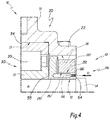
figure 4 is a sectional view along line IV-IV onfigure 3 , the axlebox comprising a housing, a bearing unit and a backing device according to the invention, the axlebox being partly shown for simplification purpose. -
Figure 1 shows abogie 2, partly represented for simplification purpose, belonging to arailway vehicle 1. Bogie 2 comprises aframe 3, twowheelset 4 and fouraxleboxes 9. Only onewheelset 4 and one axlebox 9 are shown onfigure 1 for simplification purpose. Wheelset 4 comprises twowheels 5 supported by anaxle 6, which is hidden byframe 3 and one of thewheels 5.Axlebox 9 is mounted on the outer side of thewheel 5 and secured to frame 3.Figure 1 explains the context of the application but does not show the invention. -
Figure 2 shows awheelset 4, awheel 5, anaxle 6 andsuspension systems 7, together with anaxlebox 10 according to the invention. Thus, axlebox 10 is different fromaxlebox 9 shown onfigure 1 .Suspension systems 7connect axlebox 10 to the frame, not shown, of a vehicle which is also according to the invention.Axlebox 10 is mounted onaxle 6 on the inner side of thewheel 5.Axlebox 10 supportsaxle 6, which supportswheels 5.Wheels 5,axle 6 andaxlebox box 10 are centered on a central axis X10. -
Figures 3 to 4 show axlebox 10, which comprises ahousing 20, a bearingunit 30 and abacking device 40 according to the invention. -
Housing 20 comprises anupper part 21 and alower part 22.Housing 20 defines acavity 23receiving bearing unit 30 and acavity 24 receivingbacking device 40.Cavities Axlebox 10 comprisesbolts 26 forfastening parts unit 30 is mounted insidecavity 23. -
Bearing unit 30 comprises two rolling bearings mounted against each other onaxle 6. Bearings are centered on axis X10. Each bearing comprises aninner ring 33 mounted onaxle 6, anouter ring 34 fitted incavity 23 ofhousing 20, and rollingelements 35 mounted betweeninner ring 33 andouter ring 34. Alternatively, bearingunit 30 may comprise a single bearing, of any type adapted to the present application. - Backing
device 40 is mounted onaxle 6 and insidecavity 24 next to bearingunit 30 to prevent movement of bearingunit 30 alongaxle 6. Backingdevice 40 has an annular shape. In other words, backingdevice 40 forms a backing device for bearingunit 30. Backingdevice 40 comprises aninner ring 250, anouter ring 260, and tightening means 280.Rings -
Inner ring 250 comprises a cylindricalinner surface 51, a cylindricalouter surface 252, and twolateral surfaces Lateral surface 55 is positioned in contact with aninner ring 33 of bearingunit 30, whilelateral surface 54 is preferably positioned in contact with anabutment 6A formed onaxle 6.Abutment 6A has an annular shape centered on axis X10. Diameter ofabutment 6A is reduced in comparison with known wheelsets provided with a backing device.Outer ring 262 comprises a cylindricalinner surface 262. - The tightening means 280 comprise one or
several cavities 281 formed insideinner ring 250, distributed around axis X10. For eachcavity 281, the tightening means 280 also comprise avalve 282 inserted inside theinner ring 250, in fluid communication with thecavity 281. A fluid flow is represented by an arrow F1 onfigure 4 . When actuated by filling the cavity orcavities 281 with pressurized fluid F1, eachcavity 281 is expanded, the tightening means 280 pressouter surface 252 andinner surface 262 against each other and narrowinner surface 51 ofinner ring 250 by elastic deformation thereof. Fluid F1 is preferably a hydraulic fluid. - Thanks to the invention,
backing device 40 can be quickly and easily mounted on the axle or dismounted from the axle. In practice, backingdevice 40 comprises self-locking means. - The invention also concerns a method for mounting
backing device 40 onaxle 6 and a method for dismountingbacking device 40 fromaxle 6. - The mounting method comprises a step a) of
positioning backing device 40 onaxle 6, in particular next to bearingunit 30, then a step of tightening the screws 181, of filling the cavity orcavities 281 with fluid F1, so that each cavity is expanded, thatouter surface 252 andinner surface 262 are pressed against each other and thatinner surface 51 ofinner ring 250 is narrowed aroundaxle 6. - The dismounting method comprises a step of draining fluid F1 out the cavity or
cavities 281, so that eachcavity 281 shrinks and retrieves its initial volume, that the pressure betweeninner surface 262 andouter surface 252 is released and thatinner surface 51 ofring 250 expands aroundaxle 6. Thus, backingdevice 40 andaxlebox 10 can be quickly and easily mounted or dismounted fromaxle 6. - Thus, backing
device 40 andaxlebox 10 can be quickly and easily mounted or dismounted fromaxle 6. - Other non-shown embodiments of
axlebox 10 and/or bearingdevice 40 can be implemented within the scope of the invention. In particular,axlebox housing 20, bearingunit 30,inner ring 250,outer ring 260, tightening means 280 and sealing means may have different configurations. - In addition, technical features of the different embodiments can be, in whole or part, combined with each other. Thus, axlebox 10 and
backing device 40 can be adapted to the specific requirements of the application.
Claims (8)
- Backing device (40) adapted to equip an axlebox (10) comprising a bearing unit (30) and supporting an axle (6), the backing device (40) comprising:- an inner ring (250) having an inner surface (51) and at least one outer surface (252);- at least one outer ring having an inner surface (262) facing the outer surface (252) of the inner ring (250); and- tightening means (180) which, when actuated, press the inner surface (262) of the outer ring (260) and the outer surface (252) of the inner ring (250) against each other and narrow the inner surface (51) of the inner ring (250) by elastic deformation thereof,wherein- the tightening means (280) are inserted inside the inner ring (250) and/or the outer ring (260), and- the tightening means (280) comprise at least one cavity (281) formed inside the inner ring (250) and a valve (282) inserted inside the inner ring (250) in fluid communication with the cavity (281); and wherein the tightening means (280), when actuated by filling the cavity or cavities (281) with a fluid (F1), press the outer surface (252) of the inner ring (250) and the inner surface (262) of the outer ring (260) against each other and narrow the inner surface (51) of the inner ring (250) by elastic deformation thereof.
- An axlebox (10), adapted to support an axle (6), wherein the axlebox (10) comprises a bearing unit (30) and a backing device (40) according to any claim 1.
- Axlebox (10) according to the previous claim 3, wherein the inner ring (250) of the backing device (40) has a lateral surface (55) in contact with an inner ring (33) of the bearing unit (30).
- Axlebox (10) according to any one of the previous claims 2 or 3, wherein the inner ring (250) of the backing device (40) has a lateral surface (54) in contact with an abutment (6A) formed on the axle (6).
- Axlebox (10) according to any one of the previous claims 2 to 4, comprising a housing (20) which defines a sealing labyrinth (192) with the backing device (40).
- A vehicle (1), equipped with at least one axlebox (10) according to any one of the previous claims 2 to 5.
- Method for mounting a backing device (40) on an axle (6), wherein the backing device (40) is according to claim 1, and wherein the method comprises the following steps:a) positioning the backing device (40) on the axle (6);b) filling the cavity or cavities (281) with a fluid (F1) to press the outer surface (252) of the inner ring (250) and the inner surface (262) of the outer ring (260) against each other and to narrow the inner surface (51) of the inner ring (250) elastically deformed on the axle (6).
- Method for dismounting a backing device (40) from an axle (6), wherein the backing device (40) is according to claim 1, and wherein the method comprises the following steps:c) draining the fluid out of the cavity or cavities to release the pressure between the inner surface (262) of the outer ring (260) and the outer surface (252) of the inner ring (250) and to expand the inner surface (51) of the inner ring (250) elastically deformed around the axle (6);d) removing the backing device (40) from the axle (6).
Priority Applications (1)
| Application Number | Priority Date | Filing Date | Title |
|---|---|---|---|
| EP19155117.5A EP3521130A1 (en) | 2013-11-26 | 2013-11-26 | Backing device, axlebox, vehicle and methods for mounting and dismounting such a backing device |
Applications Claiming Priority (2)
| Application Number | Priority Date | Filing Date | Title |
|---|---|---|---|
| EP19155117.5A EP3521130A1 (en) | 2013-11-26 | 2013-11-26 | Backing device, axlebox, vehicle and methods for mounting and dismounting such a backing device |
| EP13194496.9A EP2876020B1 (en) | 2013-11-26 | 2013-11-26 | Backing device, axlebox, vehicle and methods for mounting and dismounting such a backing device |
Related Parent Applications (2)
| Application Number | Title | Priority Date | Filing Date |
|---|---|---|---|
| EP13194496.9A Division EP2876020B1 (en) | 2013-11-26 | 2013-11-26 | Backing device, axlebox, vehicle and methods for mounting and dismounting such a backing device |
| EP13194496.9A Division-Into EP2876020B1 (en) | 2013-11-26 | 2013-11-26 | Backing device, axlebox, vehicle and methods for mounting and dismounting such a backing device |
Publications (1)
| Publication Number | Publication Date |
|---|---|
| EP3521130A1 true EP3521130A1 (en) | 2019-08-07 |
Family
ID=49641663
Family Applications (2)
| Application Number | Title | Priority Date | Filing Date |
|---|---|---|---|
| EP19155117.5A Withdrawn EP3521130A1 (en) | 2013-11-26 | 2013-11-26 | Backing device, axlebox, vehicle and methods for mounting and dismounting such a backing device |
| EP13194496.9A Active EP2876020B1 (en) | 2013-11-26 | 2013-11-26 | Backing device, axlebox, vehicle and methods for mounting and dismounting such a backing device |
Family Applications After (1)
| Application Number | Title | Priority Date | Filing Date |
|---|---|---|---|
| EP13194496.9A Active EP2876020B1 (en) | 2013-11-26 | 2013-11-26 | Backing device, axlebox, vehicle and methods for mounting and dismounting such a backing device |
Country Status (3)
| Country | Link |
|---|---|
| US (1) | US9358834B2 (en) |
| EP (2) | EP3521130A1 (en) |
| CN (2) | CN108506356B (en) |
Families Citing this family (3)
| Publication number | Priority date | Publication date | Assignee | Title |
|---|---|---|---|---|
| DE102016214675A1 (en) * | 2015-08-14 | 2017-02-16 | Aktiebolaget Skf | Rail vehicle traction motor bearing arrangement |
| WO2017101908A2 (en) * | 2015-12-15 | 2017-06-22 | Schaeffler Technologies AG & Co. KG | Device for detecting the rotational speed of a wheel set shaft for rail vehicles |
| DE102017208701A1 (en) * | 2017-05-23 | 2018-11-29 | Aktiebolaget Skf | Axle bearing for a rail vehicle |
Citations (7)
| Publication number | Priority date | Publication date | Assignee | Title |
|---|---|---|---|---|
| FR93444E (en) * | 1966-11-01 | 1969-03-28 | Torrington Co | Quick-release assembly for roller or ball bearings. |
| GB1393417A (en) * | 1971-08-18 | 1975-05-07 | Skf Ind Trading & Dev | Assemblies comprising machine components to be mounted in or on other machine parts |
| FR2537678A1 (en) * | 1982-12-14 | 1984-06-15 | Uni Cardan Ag | DEVICE FOR TRANSMITTING A COUPLE |
| US5489156A (en) * | 1994-12-19 | 1996-02-06 | Reliance Electric Industrial Co. | Bearing assembly utilizing improved clamping arrangement |
| US6561559B1 (en) | 1998-03-23 | 2003-05-13 | Skf Engineering And Research Centre B.V. | Bearing unit, in particular railway axlebox bearing unit, having improved anti-fretting behavior |
| US20050052043A1 (en) | 2003-09-09 | 2005-03-10 | Brister Stephen E. | Backing ring for railcar axle |
| CN202867585U (en) | 2012-09-17 | 2013-04-10 | 南车成都机车车辆有限公司 | Bearing fixing device |
Family Cites Families (7)
| Publication number | Priority date | Publication date | Assignee | Title |
|---|---|---|---|---|
| US3741614A (en) * | 1971-08-27 | 1973-06-26 | Timken Co | Roller bearings |
| DE2536116A1 (en) * | 1975-08-13 | 1977-03-03 | Kugelfischer G Schaefer & Co | Split taper sleeve roller bearing mounting - has slot and spiral end face for snap insertion and twist locking |
| CN2542877Y (en) * | 2001-11-28 | 2003-04-02 | 李桂森 | Rolling bearing of ball mill set |
| JP2003336631A (en) * | 2002-05-22 | 2003-11-28 | Koyo Seiko Co Ltd | Self-aligning bearing |
| US7788786B2 (en) * | 2006-09-05 | 2010-09-07 | Baldor Electric Company | Method for mounting a bearing assembly on a shaft |
| US8790014B2 (en) * | 2010-04-08 | 2014-07-29 | Ntn Corporation | Bearing device for axle of railway vehicle |
| EP2607733A1 (en) * | 2011-12-22 | 2013-06-26 | Aktiebolaget SKF | Bearing unit for use in an axlebox of a railway vehicle and axlebox including the same |
-
2013
- 2013-11-26 EP EP19155117.5A patent/EP3521130A1/en not_active Withdrawn
- 2013-11-26 EP EP13194496.9A patent/EP2876020B1/en active Active
-
2014
- 2014-11-26 CN CN201810305416.2A patent/CN108506356B/en not_active Expired - Fee Related
- 2014-11-26 CN CN201410696608.2A patent/CN104675867B/en not_active Expired - Fee Related
- 2014-11-26 US US14/554,356 patent/US9358834B2/en not_active Expired - Fee Related
Patent Citations (7)
| Publication number | Priority date | Publication date | Assignee | Title |
|---|---|---|---|---|
| FR93444E (en) * | 1966-11-01 | 1969-03-28 | Torrington Co | Quick-release assembly for roller or ball bearings. |
| GB1393417A (en) * | 1971-08-18 | 1975-05-07 | Skf Ind Trading & Dev | Assemblies comprising machine components to be mounted in or on other machine parts |
| FR2537678A1 (en) * | 1982-12-14 | 1984-06-15 | Uni Cardan Ag | DEVICE FOR TRANSMITTING A COUPLE |
| US5489156A (en) * | 1994-12-19 | 1996-02-06 | Reliance Electric Industrial Co. | Bearing assembly utilizing improved clamping arrangement |
| US6561559B1 (en) | 1998-03-23 | 2003-05-13 | Skf Engineering And Research Centre B.V. | Bearing unit, in particular railway axlebox bearing unit, having improved anti-fretting behavior |
| US20050052043A1 (en) | 2003-09-09 | 2005-03-10 | Brister Stephen E. | Backing ring for railcar axle |
| CN202867585U (en) | 2012-09-17 | 2013-04-10 | 南车成都机车车辆有限公司 | Bearing fixing device |
Also Published As
| Publication number | Publication date |
|---|---|
| CN108506356A (en) | 2018-09-07 |
| EP2876020A1 (en) | 2015-05-27 |
| CN104675867B (en) | 2018-11-06 |
| US20150151575A1 (en) | 2015-06-04 |
| CN104675867A (en) | 2015-06-03 |
| CN108506356B (en) | 2019-11-05 |
| US9358834B2 (en) | 2016-06-07 |
| EP2876020B1 (en) | 2020-01-22 |
Similar Documents
| Publication | Publication Date | Title |
|---|---|---|
| CN101823493B (en) | Co bogie for high-adherence heavy-load freight locomotive | |
| US3802352A (en) | Railway truck wheel and axle set | |
| AU2012216340A1 (en) | Roller bearing backing ring assembly | |
| CN203974831U (en) | Be used for the wheel of 100% low floor power truck to device | |
| AU2010200831A1 (en) | Roller bearing backing ring | |
| EP2876020B1 (en) | Backing device, axlebox, vehicle and methods for mounting and dismounting such a backing device | |
| JP2021516315A (en) | High-speed train variable gauge bogie for track vehicles | |
| CN106696602A (en) | Automotive bearing rear axle assembly | |
| US9221475B2 (en) | Self lubricated spherical transom bearing | |
| US9670962B2 (en) | Axlebox comprising split housing parts, vehicle comprising at least one such axlebox and processes | |
| CN106945463B (en) | Hub end structure of rear drive axle of minicar | |
| RU2649106C2 (en) | Towing bearing assembly for railway wheels | |
| CN201214429Y (en) | Axle-box with self-sealing bearing and baffle edge | |
| EP4294648B1 (en) | Quick change two-piece railroad wheel assembly | |
| CN2928678Y (en) | Brake airplane wheel of Qianhong-7 airplane | |
| CN104859677A (en) | Axle box device of bogie of CRH train | |
| CN108974040B (en) | Art bogie axle box and frame | |
| CN111703456B (en) | Wheel pair assembly and track-distance-variable bogie | |
| CN2928679Y (en) | Brake airplane wheel of Qianhong-7 airplane | |
| CN103640590A (en) | Rail wagon bearing device and manufacturing method thereof | |
| EP3169573B1 (en) | Bearing unit for an axlebox of a railway vehicle, axlebox, railway vehicle and maintenance process. | |
| EP4549281A1 (en) | Rear cover assembly for an axle box of a railcar bogie, wheelset, bogie, and railway vehicle comprising such rear cover assembly | |
| CN208252592U (en) | A kind of low pressure casting lightweight vehicle hub unit | |
| WO2025234384A1 (en) | Axlebox support device for railway vehicle truck | |
| CN103661933B (en) | Aircraft wheel actuator is fastened on the method on the undercarriage for carrying wheel |
Legal Events
| Date | Code | Title | Description |
|---|---|---|---|
| PUAI | Public reference made under article 153(3) epc to a published international application that has entered the european phase |
Free format text: ORIGINAL CODE: 0009012 |
|
| 17P | Request for examination filed |
Effective date: 20190201 |
|
| AC | Divisional application: reference to earlier application |
Ref document number: 2876020 Country of ref document: EP Kind code of ref document: P |
|
| AK | Designated contracting states |
Kind code of ref document: A1 Designated state(s): AL AT BE BG CH CY CZ DE DK EE ES FI FR GB GR HR HU IE IS IT LI LT LU LV MC MK MT NL NO PL PT RO RS SE SI SK SM TR |
|
| GRAP | Despatch of communication of intention to grant a patent |
Free format text: ORIGINAL CODE: EPIDOSNIGR1 |
|
| STAA | Information on the status of an ep patent application or granted ep patent |
Free format text: STATUS: GRANT OF PATENT IS INTENDED |
|
| RIC1 | Information provided on ipc code assigned before grant |
Ipc: F16C 35/073 20060101ALI20200512BHEP Ipc: B61F 15/20 20060101AFI20200512BHEP |
|
| INTG | Intention to grant announced |
Effective date: 20200615 |
|
| 18D | Application deemed to be withdrawn |
Effective date: 20201027 |