EP3521059A1 - Motorcycle tire - Google Patents
Motorcycle tire Download PDFInfo
- Publication number
- EP3521059A1 EP3521059A1 EP18213409.8A EP18213409A EP3521059A1 EP 3521059 A1 EP3521059 A1 EP 3521059A1 EP 18213409 A EP18213409 A EP 18213409A EP 3521059 A1 EP3521059 A1 EP 3521059A1
- Authority
- EP
- European Patent Office
- Prior art keywords
- tire
- rubber
- reinforcing
- coated cord
- axial direction
- Prior art date
- Legal status (The legal status is an assumption and is not a legal conclusion. Google has not performed a legal analysis and makes no representation as to the accuracy of the status listed.)
- Granted
Links
- 230000003014 reinforcing effect Effects 0.000 claims abstract description 78
- 238000004804 winding Methods 0.000 claims abstract description 53
- 238000012360 testing method Methods 0.000 description 7
- 230000000977 initiatory effect Effects 0.000 description 6
- 238000004519 manufacturing process Methods 0.000 description 6
- 230000000052 comparative effect Effects 0.000 description 5
- 230000001052 transient effect Effects 0.000 description 5
- 230000003247 decreasing effect Effects 0.000 description 4
- 238000000034 method Methods 0.000 description 4
- 239000011324 bead Substances 0.000 description 3
- 230000002093 peripheral effect Effects 0.000 description 3
- 230000000452 restraining effect Effects 0.000 description 3
- 238000010586 diagram Methods 0.000 description 2
- 230000000694 effects Effects 0.000 description 2
- 238000012935 Averaging Methods 0.000 description 1
- 229910000831 Steel Inorganic materials 0.000 description 1
- 239000010426 asphalt Substances 0.000 description 1
- 230000005540 biological transmission Effects 0.000 description 1
- 239000000835 fiber Substances 0.000 description 1
- 239000010959 steel Substances 0.000 description 1
- 238000010998 test method Methods 0.000 description 1
- 238000011144 upstream manufacturing Methods 0.000 description 1
Images


Classifications
-
- B—PERFORMING OPERATIONS; TRANSPORTING
- B60—VEHICLES IN GENERAL
- B60C—VEHICLE TYRES; TYRE INFLATION; TYRE CHANGING; CONNECTING VALVES TO INFLATABLE ELASTIC BODIES IN GENERAL; DEVICES OR ARRANGEMENTS RELATED TO TYRES
- B60C9/00—Reinforcements or ply arrangement of pneumatic tyres
- B60C9/18—Structure or arrangement of belts or breakers, crown-reinforcing or cushioning layers
- B60C9/20—Structure or arrangement of belts or breakers, crown-reinforcing or cushioning layers built-up from rubberised plies each having all cords arranged substantially parallel
- B60C9/22—Structure or arrangement of belts or breakers, crown-reinforcing or cushioning layers built-up from rubberised plies each having all cords arranged substantially parallel the plies being arranged with all cords disposed along the circumference of the tyre
- B60C9/2204—Structure or arrangement of belts or breakers, crown-reinforcing or cushioning layers built-up from rubberised plies each having all cords arranged substantially parallel the plies being arranged with all cords disposed along the circumference of the tyre obtained by circumferentially narrow strip winding
-
- B—PERFORMING OPERATIONS; TRANSPORTING
- B60—VEHICLES IN GENERAL
- B60C—VEHICLE TYRES; TYRE INFLATION; TYRE CHANGING; CONNECTING VALVES TO INFLATABLE ELASTIC BODIES IN GENERAL; DEVICES OR ARRANGEMENTS RELATED TO TYRES
- B60C9/00—Reinforcements or ply arrangement of pneumatic tyres
- B60C9/18—Structure or arrangement of belts or breakers, crown-reinforcing or cushioning layers
- B60C9/26—Folded plies
- B60C9/263—Folded plies further characterised by an endless zigzag configuration in at least one belt ply, i.e. no cut edge being present
-
- B—PERFORMING OPERATIONS; TRANSPORTING
- B60—VEHICLES IN GENERAL
- B60C—VEHICLE TYRES; TYRE INFLATION; TYRE CHANGING; CONNECTING VALVES TO INFLATABLE ELASTIC BODIES IN GENERAL; DEVICES OR ARRANGEMENTS RELATED TO TYRES
- B60C11/00—Tyre tread bands; Tread patterns; Anti-skid inserts
- B60C11/0083—Tyre tread bands; Tread patterns; Anti-skid inserts characterised by the curvature of the tyre tread
-
- B—PERFORMING OPERATIONS; TRANSPORTING
- B60—VEHICLES IN GENERAL
- B60C—VEHICLE TYRES; TYRE INFLATION; TYRE CHANGING; CONNECTING VALVES TO INFLATABLE ELASTIC BODIES IN GENERAL; DEVICES OR ARRANGEMENTS RELATED TO TYRES
- B60C9/00—Reinforcements or ply arrangement of pneumatic tyres
- B60C9/18—Structure or arrangement of belts or breakers, crown-reinforcing or cushioning layers
- B60C9/20—Structure or arrangement of belts or breakers, crown-reinforcing or cushioning layers built-up from rubberised plies each having all cords arranged substantially parallel
- B60C2009/2012—Structure or arrangement of belts or breakers, crown-reinforcing or cushioning layers built-up from rubberised plies each having all cords arranged substantially parallel with particular configuration of the belt cords in the respective belt layers
-
- B—PERFORMING OPERATIONS; TRANSPORTING
- B60—VEHICLES IN GENERAL
- B60C—VEHICLE TYRES; TYRE INFLATION; TYRE CHANGING; CONNECTING VALVES TO INFLATABLE ELASTIC BODIES IN GENERAL; DEVICES OR ARRANGEMENTS RELATED TO TYRES
- B60C9/00—Reinforcements or ply arrangement of pneumatic tyres
- B60C9/18—Structure or arrangement of belts or breakers, crown-reinforcing or cushioning layers
- B60C9/26—Folded plies
- B60C9/263—Folded plies further characterised by an endless zigzag configuration in at least one belt ply, i.e. no cut edge being present
- B60C2009/266—Folded plies further characterised by an endless zigzag configuration in at least one belt ply, i.e. no cut edge being present combined with non folded cut-belt plies
-
- B—PERFORMING OPERATIONS; TRANSPORTING
- B60—VEHICLES IN GENERAL
- B60C—VEHICLE TYRES; TYRE INFLATION; TYRE CHANGING; CONNECTING VALVES TO INFLATABLE ELASTIC BODIES IN GENERAL; DEVICES OR ARRANGEMENTS RELATED TO TYRES
- B60C2200/00—Tyres specially adapted for particular applications
- B60C2200/10—Tyres specially adapted for particular applications for motorcycles, scooters or the like
Definitions
- the present invention relates to a motorcycle tire, more particularly to a tread reinforcing layer capable of improving high-speed stability performance and cornering performance.
- Patent Document 1 discloses a motorcycle tire provided in the tread portion with a band composed a center portion having a spiral cord structure, and shoulder portions on both sides thereof having a mesh-like cord structure.
- the center portion can provide an increased binding force and a suppressed torsional rigidity.
- Patent document 1 Japanese Patent Application Publication No. 2017-177842
- a primary object of the present invention is to provide a motorcycle tire improved in the high-speed stability performance and turning or cornering performance.
- a motorcycle tire comprises:
- both edges in the tire axial direction of the spiral part are positioned outside a superimposed ground contact patch which is obtain by superimposing a ground contact patch of the tire when the tire mounted on the standard rim and inflated the standard pressure and loaded with the normal load is inclined to the right at the camber angle of 5 degrees, on a ground contact patch of the tire when the tire mounted on the standard rim and inflated the standard pressure and loaded with the normal load is inclined to the left at the camber angle of 5 degrees.
- the width in the tire axial direction of the spiral part is less than 60 % of the width in the tire axial direction of the tread portion.
- the angle of each reinforcing cord in the spiral part with respect to the tire circumferential direction is not more than 5 degrees.
- the profile of the tread surface of the tread portion has, in the crown region, a radius or radii of less than 60 % of the width in the tire axial direction of the tread portion.
- the rubber-coated cord strip forming the spiral part has only one reinforcing cord embedded therein.
- the spiral part is extended in the tire axial direction so that its both edges are positioned outside the ground contact patch of the tire when the tire mounted on the standard rim and inflated to the standard pressure is contacted with a flat surface and loaded with the normal load at the camber angle of zero. That is, the spiral part extends over the ground contact patch during straight running, therefore, the torsional rigidity of the ground contact patch during straight running becomes decreased to generate limited cornering power. As a result, reaction forces and vibrations caused by, for example, gaps of a road surface are reduced, and the sense of ground contacting is improved, therefore, high-speed stability performance during straight running can be improved.
- the spiral part is extended to a region mainly contacting with the ground when initiating a turn, therefore, the change in the rigidity of a portion contacting with the ground when the running state is changed from straight running to initiation of a turn can be suppressed. Thereby, the transient characteristics are improved, and the cornering performance can be further improved.
- Fig. 1 is a meridian cross sectional view of a motorcycle tire as an embodiment of present invention under its normal state.
- the "normal state” is a state in which the tire 1 is mounted on a standard rim (not shown), inflated to a standard pressure, and loaded with no tire load.
- the “standard rim” is a rim specified for the tire in the standard system comprising the standard on which the tire 1 is based, for example, “Standard rim” for JATMA, "Design rim “ for TRA, “Measuring rim” for ETRTO.
- the “standard pressure” is an air pressure specified for the tire in the standard system comprising the standard on which the tire 1 is based, for example, “Maximum air pressure” for JATMA, "Inflation pressure” for ETRTO, Maximum value specified in "TIRE LOAD LIMITS AT VARIOUS COLD INFLATION PRESSURES" table for TRA.
- the tire 1 in this embodiment comprises a tread portion 2 having a tread surface 2a coming into contact with the ground, a toroidal carcass 6, and a tread reinforcing layer 7 disposed radially outside the carcass 6 in the tread portion 2.
- the tread portion 2 is curved in an arc shape being convex toward the radially outside, and has a pair of tread edges TE.
- the tread edges TE are positioned on the most outsides in the tire axial direction.
- the tread portion 2 has a crown region 2C including the tire equator C and a pair of shoulder regions 2S on both sides thereof.
- the shoulder regions 2S are regions extending from the edges in the tire axial direction of the crown region 2C to the tread edges TE.
- the carcass 6 is composed of at least one carcass ply 6A.
- the carcass ply 6A is made of carcass cords rubberized with an unvulcanized topping rubber, and arranged at an angle of 75 to 90 degrees with respect to the tire equator C.
- the carcass ply 6A comprises a main portion 6a extending from the tread portion 2 to bead cores 5 on both sides respectively disposed in the bead portions 4 through the sidewall portions 3, and a pair of turnup portions 6b extending continuously from the main portion 6a.
- the tread reinforcing layer 7 extends and curves along the tread portion 2 and is formed over the substantially entire width of the tread portion 2. As a result, the tread reinforcing layer 7 can increase the rigidity of the tread portion 2 over the entire width of the tread portion 2.
- the axial width wt of the tread reinforcing layer 7 is set in a range from 75 % to 95 % of the axial width Tw between the tread edges TE of the tread portion 2.
- the tread reinforcing layer 7 of this embodiment is formed by winding a rubber-coated cord strip 9 around the carcass 6.
- Fig. 2 is a perspective view of the rubber-coated cord strip 9.
- the rubber-coated cord strip 9 has two side edges 9s extending in the longitudinal direction thereof.
- the width w1 of the rubber-coated cord strip 9 is preferably set in a range from 2.5 to 12.0 mm, for example.
- the thickness t1 of the rubber-coated cord strip 9 is preferably set in a range from 0.6 to 3.0 mm, for example.
- the rubber-coated cord strip 9 is formed by covering one or more reinforcing cords 10 with an unvulcanized topping rubber 11.
- the reinforcing cords 10 for example, steel cords and/or organic fiber cords are preferably used.
- the reinforcing cords 10 extend in parallel with the side edge 9s.
- Fig. 3 is a developed plan view of the tread reinforcing layer 7 which is developed in the tire circumferential direction and axial direction.
- the rubber-coated cord strip 9 is indicated by a single solid line (corresponding to the center line in the widthwise direction) for convenience sake.
- the tread portion 2 is curved in an arc shape protruding radially outwardly, the circumference of the tire is different between the tire equator C side and the tread edges TE side.
- the tread reinforcing layer 7 is illustrated based on the angle with respect to the tire circumferential direction, the developed plan view of the tread reinforcing layer 7 is shown as a rectangle.
- the tread reinforcing layer 7 comprises a crown reinforcing part 7C formed by winding a rubber-coated cord strip 9 around the crown region 2C, and a pair of shoulder reinforcing parts 7S each formed by winding a rubber-coated cord strip 9 around one of the shoulder regions 2S.
- the crown reinforcing part 7C and the pair of shoulder reinforcing parts 7S are formed from separate rubber-coated cord strips 9.
- the crown reinforcing part 7C and the pair of shoulder reinforcing parts 7S may be formed from one continuous rubber-coated cord strip 9.
- Each the shoulder reinforcing parts 7S in this embodiment comprises a plurality of inclining segments 13 in which the rubber-coated cord strip 9 is inclined, and a plurality of circumferential segments 14 in which the rubber-coated cord strip 9 extends in the tire circumferential direction.
- the plurality of inclining segments 13 of this embodiment includes a plurality of first inclining segments 15 inclined to one side (diagonally right up in the figure) with respect to the tire circumferential direction, and a plurality of second inclining segments 16 inclined to the other side (diagonally right down in the figure) opposite to the plurality of first inclining segments 15.
- the shoulder reinforcing part 7S in this embodiment includes a mesh part 20 in which the first inclining segments 15 intersect the second inclining segments 16 while forming a plurality of spaces 17.
- a tension acting on a part of the mesh part 20 can be dispersed over a wide range of the mesh part 20 through the rubber-coated cord strip 9, so the rigidity of the shoulder region 2S is increased and the cornering performance is improved.
- the crown reinforcing part 7C in this embodiment includes a spiral part 21 which is composed of more than one turn of a rubber-coated cord strip 9 extending substantially in parallel with the tire circumferential direction.
- Such crown reinforcing part 7C exerts a large restraining force on the crown region 2C contacting with the ground during straight running, so the deformation of the tread portion 2 due to the centrifugal force at high speed straight running can be suppressed. Further, such crown reinforcing part 7C can suppress the increase in torsional rigidity of the crown region 2C to produce a relatively low cornering power, therefore, it is possible to reduce reaction forces and vibrations caused by, for example, gaps of a road surface, to improve the sense of ground contacting. Thus, the crown reinforcing part 7C can improve the high-speed stability performance.
- the expression "the rubber-coated cord strip extends substantially in parallel with the tire circumferential direction” means that the angle ⁇ 1 of the rubber-coated cord strip 9 with respect to the tire circumferential direction is in a range from 0 to 8 degrees. Further, in this specification, the values of the angle ⁇ 1 refer to those obtained by averaging the angle ⁇ 1 over the circumference of the tire in order to exclude a portion inclined at a large angle.
- both edges 21e in the tire axial direction of the spiral part 21 are, in the tire axial direction, positioned outside the ground contact patch 2A of the tire 1 which occurs when the tire 1 in its normal state is contacted with a flat road surface at the camber angle of 0 degrees and is loaded with a normal load.
- the spiral part 21 is disposed over a wider range than the ground contact patch during straight running.
- the spiral part 21 is further formed in a region mainly contacting with the ground when initiating a turn, if the running state is changed from straight running to initiation of a turn, the change in the rigidity is suppressed, and the transient characteristics are improved to improve the cornering performance.
- the both edges 21e of the spiral part 21 are positioned outside the ground contact patch 2A when the slip angle of the tire 1 is in a range from 0 to 1 degree.
- the width wa in the tire axial direction of the spiral part 21 disposed in the crown region 2C is set as being larger than the width WA of the ground contact patch 2A. If the width wa in the tire axial direction is smaller than the width WA of the ground contact patch 2A, the sense of ground contacting about the ground contact patch during straight running is deteriorated, and the restraining force thereon is reduced, and the high-speed stability performance is deteriorated.
- the "normal load” is a load specified for the tire in the standard system comprising the standard on which the tire 1 is based, for example, "Maximum load capacity” for JATMA, "Load capacity” for ETRTO, Maximum value specified in "TIRE LOAD LIMITS AT VARIOUS COLD INFLATION PRESSURES" table for TRA.
- the crown reinforcing part 7C in this embodiment is formed by the spiral part 21 only.
- the width wa in the tire axial direction of the spiral part 21 in this embodiment is equal to the width Wb in the tire axial direction of the crown region 2C.
- the shoulder reinforcing parts 7S in this embodiment are each formed by the mesh part 20 only.
- both edges 21e of the spiral part 21 are positioned outside a superimposed ground contact patch 2B, wherein
- the width wa in the tire axial direction of the spiral part 21 is less than 60 % of the width TW in the tire axial direction of the tread portion 2.
- the width Wa in the tire axial direction of the spiral part 21 is set in a range from 30 % to 55 % of the width TW in the tire axial direction of the tread portion 2.
- Fig. 4(a) shows a part of the spiral part 21.
- the angle ⁇ 3 of the reinforcing cord 10 with respect to the tire circumferential direction is not more than 5 degrees.
- the side edges 9s of the rubber-coated cord strip 9 which are adjacent to each other in the tire axial direction are substantially in contact with each other.
- the side edges 9s of the rubber-coated cord strip 9 which are adjacent to each other in the tire axial direction may be separated from each other, or overlapped with each other.
- the center of the width in the tire axial direction of the spiral part 21 in this embodiment is positioned at the tire equator C.
- the rubber-coated cord strip 9 forming the spiral part 21 has only one reinforcing cord 10 embedded therein. Thereby, the torsional rigidity of the crown region 2C is increased. It is preferable that such rubber-coated cord strip 9 has a width w1 of from 2.5 to 3.5 mm for example, and a thickness t1 of from 0.6 to 3.0 mm for example.
- the tread surface of the tread portion 2 has a profile which has, in the crown region 2C, a radius or radii R1 of less than 60 % of the width TW in the tire axial direction of the tread portion 2.
- Such crown region 2C improves the transient characteristics when the running state is changed from straight running to initiation of a turn, therefore, the cornering performance can be improved. If the tread radius/radii R1 in the crown region 2C is/are excessively small, there is a possibility that straight running becomes unstable, and the high-speed stability performance is deteriorated.
- the tread radius/radii R1 in the crown region 2C is/are set to be not less than 30 % of the width TW in the tire axial direction of the tread portion 2.
- the profile in the crown region 2C is made up of a plurality of circular arcs having the different radii R1.
- the profile of the tread surface has a radius or radii R2 smaller than the radius/radii R1 in the crown region 2C.
- the turning radius can be decreased, and thereby the cornering performance is improved.
- the radius/radii R2 in the shoulder regions 2S is/are set in a range from 20 % to 50 % of the width TW in the tire axial direction of the tread portion 2.
- the circumferential segments 14 of the mesh part 20 in this embodiment are disposed at both edges 20e in the tire axial direction of the mesh part 20.
- the circumferential segments 14 in this embodiment include a plurality of outer circumferential segments 18 on the tread edge TE side, and a plurality of inner circumferential segments 19 on the tire equator C side.
- the outer circumferential segments 18 are positioned in a region which contacts with the ground mainly during full-bank cornering, therefore, the torsional rigidity of this region is relatively decreased to cause limited cornering power. For this reason, reaction forces and vibrations caused by, for example, gaps of a road surface are reduced, and the sense of ground contacting and the cornering performance during full-bank cornering can be improved.
- the inner circumferential segments 19 increase the rigidity of a region close to the crown region 2C, and decrease the rigidity change between the crown region 2C and the shoulder regions 2S. Thereby, the transient characteristics when the running state is changed from straight running to initiation of a turn can be improved, therefore, the cornering performance is further improved.
- Ends in the tire circumferential direction of the circumferential segments 14 are, for example, connected to the first inclining segments 15 and the second inclining segments 16.
- both of the ends of each of the circumferential segments 14 are connected to two of the circumferentially adjacent first inclining segments 15, or alternatively two of the circumferentially adjacent second inclining segments 16.
- the circumferential segments 14 are arranged in line in the tire circumferential direction.
- the circumferential segments 14 are arranged as if they continue in the tire circumferential direction, making continuous one turn 14A having a circumferential length La at each edge 20e. This helps to further improve the high-speed stability performance and the cornering performance.
- Fig. 4(b) shows a part of the mesh part 20.
- the angle ⁇ 5 of the reinforcing cords 10 in the inclining segments 13 is preferably 3 to 10 degrees, more preferably 4 to 6 degrees with respect to the tire circumferential direction.
- the angle ⁇ 6 of the reinforcing cords 10 in the circumferential segments 14 with respect to the tire circumferential direction is smaller than the angle ⁇ 5 of the inclining segments 13, and it is preferable that the angle ⁇ 6 is not more than 5 degrees, more preferably not more than 3 degrees, still more preferably not more than 1 degrees.
- Fig. 5 shows an apparatus T for manufacturing the tread reinforcing layer 7.
- the manufacturing apparatus T employed in this embodiment has a well-known structure comprising a base 33, a substantially cylindrical drum 34 rotatably supported by the base 33, and an applicator 35 for supplying the rubber-coated cord strip 9 to the drum 34.
- the base 33 comprises a rotating shaft 33c rotatably holding the drum 34. Further, the base 33 comprises a power transmission device for rotating the rotating shaft 33c, a control unit (not shown) for controlling the rotation and the like.
- the drum 34 comprises: an annular core 36 provided with an outer peripheral surface 36a having a profile approximate to that of the tread surface 2a of the tire 1; a device 37 for radially expanding/contracting the annular core 36, for example, made from a rubber member; and a tire holding device 38 for holding a raw tire main body K including bead cores 5.
- a rubber-coated cord strip 9 is wound on the raw tire main body K.
- the applicator 35 is, for example, a conveyor which supplies the rubber-coated cord strip 9, which is placed on the conveying surface, to the drum 34.
- a rubber extruder (not shown) for continuously extruding the rubber of the rubber-coated cord strip 9.
- the applicator 35 is supported by, for example, a three-dimensional moving device (not shown) so that the applicator can be moved in the axial direction and radial direction of the drum 34.
- a method for manufacturing the tire in this embodiment comprises a step of preparing a raw tire main body K, and a step of making the tread reinforcing layer 7 by winding the rubber-coated cord strip 9 around the outer peripheral surface of the raw tire main body K.
- the raw tire main body K includes the carcass 6.
- the step of preparing a raw tire main body K its detailed explanation is omitted since a well-known manufacturing method can be employed.
- the winding step includes:
- the rubber-coated cord strips 9 are wound on a surface 6e which is the radially outer surface of the carcass 6 of the raw tire main body K.
- Figs. 6(a) and 6(b) conceptually illustrate the first shoulder winding step of this embodiment.
- Fig. 6(a) is a plan view showing a state of the shoulder reinforcing part 7S immediately after the winding of the rubber-coated cord strip 9 is started, wherein turns of the rubber-coated cord strip 9 not yet wound are indicated by imaginary lines, and a turn of the rubber-coated cord strip 9 partially wound is indicated by solid lines and reference numeral 9f.
- Fig. 6 (b) is a plan view showing a state of the shoulder reinforcing part 7S when the winding of the rubber-coated cord strip 9 has been progressed more than Fig. 6(a) , wherein a turn of the rubber-coated cord strip 9 completely wound is indicated by solid lines and reference numeral 9h, and a turn partially wound is indicated by solid lines and reference numeral 9d.
- a winding start end 9d of the rubber-coated cord strip 9 when starting the winding is fixed, for example, to one edge 20e of the mesh part 20.
- the winding start end 9d may be fixed to the outer edge 20e of the mesh part 20 or a position on one of the inclining portions 13.
- a plurality of reinforcing cords 10, for example, three reinforcing cords 10 are embedded in the topping rubber.
- the applicator 35 applies the rubber-coated cord strip 9 to the surface 6e of the rotating annular core 36 while reciprocating between the edges 20e.
- the rubber-coated cord strip 9 is wound in a zigzag shape comprising the first inclining segments 15 and the second inclining segments 16 so that the side edges 9s (shown in Fig. 2 ) of the rubber-coated cord strip 9 are not in contact with each other.
- a first inclining segment 15, an outer circumferential segment 18, a second inclining segment 16, and an inner circumferential segment 18 are wound in this order, and these are repeated to make one turn until a plurality of turns are formed.
- one end and the other end of each inner circumferential segment 18 are respectively connected to one of the first inclining segments 15 and one of the second inclining segments 16, and one end and the other end of each outer circumferential segment 19 are respectively connected to one of the second inclining segments 16 and one of the first inclining segments 15.
- the rubber-coated cord strip 9 can be formed into the mesh part 20 having spaces 17 surrounded by the first inclining segments 15 and the second inclining segments 16.
- the winding stop end 9e of the rubber-coated cord strip 9 when ending the winding is fixed so as to continue to the winding start end 9d in the tire circumferential direction.
- the crown winding step is performed for example.
- the crown winding step is performed, using one rubber-coated cord strip 9 different from that in the first shoulder winding step.
- a single reinforcing cord 10 is embedded along the longitudinal direction.
- the rubber-coated cord strip 9 is wound spirally more than one turn from one edge 21e to the other edge 21e in the tire axial direction of the spiral part 21 by the use of the applicator 35.
- the winding start end and the winding stop end of the rubber-coated cord strip 9 are positioned at substantially same circumferential points at different axial positions.
- the second shoulder winding step is performed.
- the second shoulder winding step is performed by using one rubber-coated cord strip 9 different from that in the crown winding step. Since the second shoulder winding step is performed in the same manner as the first shoulder winding step, its detailed explanation is omitted. In this way, the tread reinforcing layer 7 is formed.
- Figs. 7(a) and 7(b) schematically show a first shoulder winding step or a second shoulder winding step of another embodiment.
- Fig. 7(a) is a plan view showing a state of the shoulder reinforcing part 7S immediately after the winding of the rubber-coated cord strip 9 is started, wherein turns of the rubber-coated cord strip 9 not yet wound are indicated by imaginary lines, and a turn of the rubber-coated cord strip 9 partially wound is indicated by solid lines and reference numeral 9f.
- Fig. 7(b) is a plan view showing a state of the shoulder reinforcing part 7S when the winding of the rubber-coated cord strip 9 has been progressed more than Fig. 7(a) , wherein a turn of the rubber-coated cord strip 9 partially wound is indicated by reference numeral 9h, and the rubber-coated cord strip 9 is wound in the order indicated by allowed imaginary lines a, b, c and d.
- the winding start end 9d at the beginning of winding of the rubber-coated cord strip 9 is fixed to one edge 20e of the mesh part 20.
- the winding start end 9d may be fixed to the other edge 20e of the mesh part 20 or a position on one of the inclining portions 13.
- the applicator 35 supplies the rubber-coated cord strip 9 to the outer peripheral surface 36a of the rotating annular core 36 while reciprocating between the edges 20e.
- the rubber-coated cord strip 9 is wound in the order of a first inclining segment 15, an inner circumferential segment 19, a first inclining segment 15, an outer circumferential segment 18, a first inclining segment 15 ---.
- the rubber-coated cord strip 9 is wound in the order of a second inclining segment 16, an inner circumferential segment 19, a second inclining segment 16, an outer circumferential segment 18, a second inclining segment 16 ---.
- the mesh part 20 is formed such that both ends of each of the outer circumferential segments 18 and inner circumferential segments 19 are connected to two of the first inclining segments 15 adjacent to each other in the tire circumferential direction, or alternatively two of the second inclining segments 16 adjacent to each other in the tire circumferential direction. And the side edges 15s of the first inclining segments 15 are arranged so as not to contact with each other, and the side edges 16s of the second inclining segments 16 are arranged so as not to contact with each other.
- the shoulder reinforcing part 7S is formed as the mesh part 20 having a plurality of spaces 17 surrounded by the first inclining segments 15 and the second inclining segments 16.
- test tires were mounted on all wheels of a 1300cc motorcycle under the following conditions.
- the cornering force of each test tire was measured under the following conditions in order to obtain a value CF(-1 degree) at the slip angle of -1 degree and a value CF(+1 degree) at the slip angle of +1 degree.
Abstract
Description
- The present invention relates to a motorcycle tire, more particularly to a tread reinforcing layer capable of improving high-speed stability performance and cornering performance.
- Patent Document 1 below discloses a motorcycle tire provided in the tread portion with a band composed a center portion having a spiral cord structure, and shoulder portions on both sides thereof having a mesh-like cord structure. Thus, the center portion can provide an increased binding force and a suppressed torsional rigidity. As a result, relatively, the torsional rigidity of the shoulder portions is enhanced, and the turning or cornering performance is improved.
Patent document 1: Japanese Patent Application Publication No.2017-177842 - In recent years, on the other hand, along with the improvement in performance of motorcycles, motorcycle tires are required to be further improved in high-speed stability performance and cornering performance.
- Therefore, the present invention was made in view of the above circumstances, and a primary object of the present invention is to provide a motorcycle tire improved in the high-speed stability performance and turning or cornering performance.
- According to the present invention, a motorcycle tire comprises:
- a toroidal carcass, and
- a tread reinforcing layer disposed radially outside the carcass in a tread portion,
- the tread reinforcing layer comprising
a crown reinforcing part formed by winding a rubber-coated cord strip of at least one rubberized reinforcing cord covered with topping rubber, around a crown region including the tire equator, and
a pair of shoulder reinforcing parts each formed by winding a rubber-coated cord strip around a shoulder region on each side of the crown region,
wherein - the crown reinforcing part includes a spiral part in which the rubber-coated cord strip is wound spirally and circumferentially of the tire more than one turns,
- each of the shoulder reinforcing parts comprises
a plurality of first inclining segments in which the rubber-coated cord strip is inclined to one side with respect to the tire circumferential direction, and
a plurality of second inclining segments in which the rubber-coated cord strip is inclined to the other side opposite to the plurality of first inclining segments, with respect to the tire circumferential direction, so that the first inclining segments intersect the second inclining segments, - side edges of the first inclining segments are arranged so as not to contact with each other, and side edges of the second inclining segments are arranged so as not to contact with each other, whereby a mesh part having a mesh structure with a plurality of spaces is formed,
wherein - both edges in the tire axial direction of the spiral part are, in the tire axial direction, positioned outside a ground contact patch of the tire when the tire mounted on a standard rim and inflated to a standard pressure is contacted with a flat surface and loaded with a normal load at the camber angle of zero.
- In the motorcycle tire according to the present invention, it is preferable that both edges in the tire axial direction of the spiral part are positioned outside a superimposed ground contact patch which is obtain by superimposing a ground contact patch of the tire when the tire mounted on the standard rim and inflated the standard pressure and loaded with the normal load is inclined to the right at the camber angle of 5 degrees, on a ground contact patch of the tire when the tire mounted on the standard rim and inflated the standard pressure and loaded with the normal load is inclined to the left at the camber angle of 5 degrees.
- In the motorcycle tire according to the present invention, it is preferable that the width in the tire axial direction of the spiral part is less than 60 % of the width in the tire axial direction of the tread portion.
- In the motorcycle tire according to the present invention, it is preferable that the angle of each reinforcing cord in the spiral part with respect to the tire circumferential direction is not more than 5 degrees.
- In the motorcycle tire according to the present invention, it is preferable that, in the meridian cross section of the tire when the tire is mounted on the standard rim and inflated the standard pressure and loaded with no tire load, the profile of the tread surface of the tread portion has, in the crown region, a radius or radii of less than 60 % of the width in the tire axial direction of the tread portion.
- In the motorcycle tire according to the present invention, it is preferable that the rubber-coated cord strip forming the spiral part has only one reinforcing cord embedded therein.
- In the motorcycle tire according to the present invention, the spiral part is extended in the tire axial direction so that its both edges are positioned outside the ground contact patch of the tire when the tire mounted on the standard rim and inflated to the standard pressure is contacted with a flat surface and loaded with the normal load at the camber angle of zero. That is, the spiral part extends over the ground contact patch during straight running, therefore, the torsional rigidity of the ground contact patch during straight running becomes decreased to generate limited cornering power. As a result, reaction forces and vibrations caused by, for example, gaps of a road surface are reduced, and the sense of ground contacting is improved, therefore, high-speed stability performance during straight running can be improved. Further, the spiral part is extended to a region mainly contacting with the ground when initiating a turn, therefore, the change in the rigidity of a portion contacting with the ground when the running state is changed from straight running to initiation of a turn can be suppressed. Thereby, the transient characteristics are improved, and the cornering performance can be further improved.
- Thus, in the motorcycle tire according to the present invention, it is possible to further improve the high-speed stability performance and the cornering performance.
-
-
Fig. 1 is a cross sectional view of a motorcycle tire as an embodiment of the present invention. -
Fig. 2 is a schematic perspective view of a rubber-coated cord strip. -
Fig. 3 is a schematic developed plan view of the tread reinforcing layer. -
Fig. 4(a) is an enlarged partial view showing the spiral part shown inFig. 3 . -
Fig. 4(b) is an enlarged partial view showing the mesh part shown inFig. 3 . -
Fig. 5 is a schematic cross sectional view of an apparatus for manufacturing the tread reinforcing layer. -
Fig. 6(a) and Fig. 6(b) are diagrams for explaining a process of forming the shoulder reinforcing part of this embodiment. -
Fig. 7(a) and Fig. 7(b) are diagrams for explaining a process of forming the shoulder reinforcing part of another embodiment. - Embodiments of the present invention will now be described in detail with reference to the accompanying drawings.
-
Fig. 1 is a meridian cross sectional view of a motorcycle tire as an embodiment of present invention under its normal state. - The "normal state" is a state in which the tire 1 is mounted on a standard rim (not shown), inflated to a standard pressure, and loaded with no tire load.
- In the present specification, unless otherwise noted, dimensions of each part of the tire 1 refer to values measured under the normal state.
- The "standard rim" is a rim specified for the tire in the standard system comprising the standard on which the tire 1 is based, for example, "Standard rim" for JATMA, "Design rim " for TRA, "Measuring rim " for ETRTO.
- The "standard pressure" is an air pressure specified for the tire in the standard system comprising the standard on which the tire 1 is based, for example, "Maximum air pressure" for JATMA, "Inflation pressure" for ETRTO, Maximum value specified in "TIRE LOAD LIMITS AT VARIOUS COLD INFLATION PRESSURES" table for TRA.
- As shown in
Fig. 1 , the tire 1 in this embodiment comprises atread portion 2 having atread surface 2a coming into contact with the ground, atoroidal carcass 6, and atread reinforcing layer 7 disposed radially outside thecarcass 6 in thetread portion 2. - The
tread portion 2 is curved in an arc shape being convex toward the radially outside, and has a pair of tread edges TE. The tread edges TE are positioned on the most outsides in the tire axial direction. - The
tread portion 2 has acrown region 2C including the tire equator C and a pair ofshoulder regions 2S on both sides thereof. Theshoulder regions 2S are regions extending from the edges in the tire axial direction of thecrown region 2C to the tread edges TE. - The
carcass 6 is composed of at least onecarcass ply 6A. For example, thecarcass ply 6A is made of carcass cords rubberized with an unvulcanized topping rubber, and arranged at an angle of 75 to 90 degrees with respect to the tire equator C. For example, thecarcass ply 6A comprises amain portion 6a extending from thetread portion 2 to beadcores 5 on both sides respectively disposed in thebead portions 4 through thesidewall portions 3, and a pair ofturnup portions 6b extending continuously from themain portion 6a. - In the meridian cross section of the tire, the
tread reinforcing layer 7 extends and curves along thetread portion 2 and is formed over the substantially entire width of thetread portion 2. As a result, thetread reinforcing layer 7 can increase the rigidity of thetread portion 2 over the entire width of thetread portion 2. - From this point of view, it is preferable that the axial width wt of the
tread reinforcing layer 7 is set in a range from 75 % to 95 % of the axial width Tw between the tread edges TE of thetread portion 2. - The
tread reinforcing layer 7 of this embodiment is formed by winding a rubber-coatedcord strip 9 around thecarcass 6. -
Fig. 2 is a perspective view of the rubber-coatedcord strip 9. As shown inFig. 2 , the rubber-coatedcord strip 9 has twoside edges 9s extending in the longitudinal direction thereof.
The width w1 of the rubber-coatedcord strip 9 is preferably set in a range from 2.5 to 12.0 mm, for example.
The thickness t1 of the rubber-coatedcord strip 9 is preferably set in a range from 0.6 to 3.0 mm, for example. - For example, the rubber-coated
cord strip 9 is formed by covering one or more reinforcingcords 10 with anunvulcanized topping rubber 11.
As the reinforcingcords 10, for example, steel cords and/or organic fiber cords are preferably used.
In this embodiment, the reinforcingcords 10 extend in parallel with theside edge 9s. -
Fig. 3 is a developed plan view of thetread reinforcing layer 7 which is developed in the tire circumferential direction and axial direction. InFig. 3 , the rubber-coatedcord strip 9 is indicated by a single solid line (corresponding to the center line in the widthwise direction) for convenience sake. Incidentally, as thetread portion 2 is curved in an arc shape protruding radially outwardly, the circumference of the tire is different between the tire equator C side and the tread edges TE side. InFig. 3 , however, since thetread reinforcing layer 7 is illustrated based on the angle with respect to the tire circumferential direction, the developed plan view of thetread reinforcing layer 7 is shown as a rectangle. - In this embodiment, as shown in
Fig. 3 , thetread reinforcing layer 7 comprises
acrown reinforcing part 7C formed by winding a rubber-coatedcord strip 9 around thecrown region 2C, and
a pair ofshoulder reinforcing parts 7S each formed by winding a rubber-coatedcord strip 9 around one of theshoulder regions 2S. - For example, the
crown reinforcing part 7C and the pair ofshoulder reinforcing parts 7S are formed from separate rubber-coated cord strips 9. However, thecrown reinforcing part 7C and the pair ofshoulder reinforcing parts 7S may be formed from one continuous rubber-coatedcord strip 9. - Each the
shoulder reinforcing parts 7S in this embodiment comprises
a plurality of incliningsegments 13 in which the rubber-coatedcord strip 9 is inclined, and
a plurality ofcircumferential segments 14 in which the rubber-coatedcord strip 9 extends in the tire circumferential direction. - The plurality of inclining
segments 13 of this embodiment includes
a plurality offirst inclining segments 15 inclined to one side (diagonally right up in the figure) with respect to the tire circumferential direction, and
a plurality ofsecond inclining segments 16 inclined to the other side (diagonally right down in the figure) opposite to the plurality offirst inclining segments 15.
Thereby, the torsional rigidity of theshoulder regions 2S is increased to cause a high cornering power. - In each of the
shoulder reinforcing parts 7S in this embodiment, side edges 15s of thefirst inclining segments 15 are arranged so as not to contact with each other, andside edges 16s of thesecond inclining segments 16 are arranged so as not to contact with each other. Thereby, theshoulder reinforcing part 7S in this embodiment includes amesh part 20 in which thefirst inclining segments 15 intersect thesecond inclining segments 16 while forming a plurality ofspaces 17. Thus, a tension acting on a part of themesh part 20 can be dispersed over a wide range of themesh part 20 through the rubber-coatedcord strip 9, so the rigidity of theshoulder region 2S is increased and the cornering performance is improved. - The
crown reinforcing part 7C in this embodiment includes aspiral part 21 which is composed of more than one turn of a rubber-coatedcord strip 9 extending substantially in parallel with the tire circumferential direction. - Such
crown reinforcing part 7C exerts a large restraining force on thecrown region 2C contacting with the ground during straight running, so the deformation of thetread portion 2 due to the centrifugal force at high speed straight running can be suppressed. Further, suchcrown reinforcing part 7C can suppress the increase in torsional rigidity of thecrown region 2C to produce a relatively low cornering power, therefore, it is possible to reduce reaction forces and vibrations caused by, for example, gaps of a road surface, to improve the sense of ground contacting. Thus, thecrown reinforcing part 7C can improve the high-speed stability performance. - In this specification, the expression "the rubber-coated cord strip extends substantially in parallel with the tire circumferential direction" means that the angle θ1 of the rubber-coated
cord strip 9 with respect to the tire circumferential direction is in a range from 0 to 8 degrees. Further, in this specification, the values of the angle θ1 refer to those obtained by averaging the angle θ1 over the circumference of the tire in order to exclude a portion inclined at a large angle. - As shown in
Fig. 1 , bothedges 21e in the tire axial direction of thespiral part 21 are, in the tire axial direction, positioned outside theground contact patch 2A of the tire 1 which occurs when the tire 1 in its normal state is contacted with a flat road surface at the camber angle of 0 degrees and is loaded with a normal load. Thus, thespiral part 21 is disposed over a wider range than the ground contact patch during straight running. Thereby, in the ground contact patch during straight running, the torsional rigidity becomes decreased, and a relatively low cornering power occurs. For this reason, reaction forces and vibrations caused by, for example, gaps of a road surface are reduced, and the improvement in the sense of ground contacting is assured, therefor, the high-speed stability performance during straight running is enhanced.
Since thespiral part 21 is further formed in a region mainly contacting with the ground when initiating a turn, if the running state is changed from straight running to initiation of a turn, the change in the rigidity is suppressed, and the transient characteristics are improved to improve the cornering performance.
In view of this, it is preferable that the bothedges 21e of thespiral part 21 are positioned outside theground contact patch 2A when the slip angle of the tire 1 is in a range from 0 to 1 degree. - As described above, in the present invention, attention is paid to a relation between the width wa in the tire axial direction of the
spiral part 21 disposed in thecrown region 2C, and the width WA in the tire axial direction of theground contact patch 2A. And, in order to improve the high-speed stability performance and the cornering performance, in the present invention, the width wa in the tire axial direction is set as being larger than the width WA of theground contact patch 2A.
If the width wa in the tire axial direction is smaller than the width WA of theground contact patch 2A, the sense of ground contacting about the ground contact patch during straight running is deteriorated, and the restraining force thereon is reduced, and the high-speed stability performance is deteriorated. - The "normal load" is a load specified for the tire in the standard system comprising the standard on which the tire 1 is based, for example, "Maximum load capacity" for JATMA, "Load capacity" for ETRTO, Maximum value specified in "TIRE LOAD LIMITS AT VARIOUS COLD INFLATION PRESSURES" table for TRA.
- The
crown reinforcing part 7C in this embodiment is formed by thespiral part 21 only.
Thus, the width wa in the tire axial direction of thespiral part 21 in this embodiment is equal to the width Wb in the tire axial direction of thecrown region 2C. - The
shoulder reinforcing parts 7S in this embodiment are each formed by themesh part 20 only. - In order to more efficiently improve the transient characteristics during cornering, it is preferred that the both
edges 21e of thespiral part 21 are positioned outside a superimposedground contact patch 2B, wherein - the superimposed
ground contact patch 2B is obtained by superimposing - a ground contact patch of the tire 1 when the tire 1 mounted on the standard rim and inflated the standard pressure and loaded with the normal load is inclined to the right at the camber angle of 5 degrees, on
- a ground contact patch of the tire 1 when the tire 1 mounted on the standard rim and inflated the standard pressure and loaded with the normal load is inclined to the left at the camber angle of 5 degrees.
- It is preferable that the width wa in the tire axial direction of the
spiral part 21 is less than 60 % of the width TW in the tire axial direction of thetread portion 2. Thereby, during cornering, theshoulder regions 2S provided with themesh part 20 contact with the ground and the cornering performance can be maintained at high levels. - In order to improve the high-speed stability performance and the cornering performance in good balance, it is preferred that the width Wa in the tire axial direction of the
spiral part 21 is set in a range from 30 % to 55 % of the width TW in the tire axial direction of thetread portion 2. -
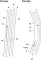
Fig. 4(a) shows a part of thespiral part 21.
In thespiral part 21, it is preferable that, as shown inFig. 4 , the angle θ3 of the reinforcingcord 10 with respect to the tire circumferential direction is not more than 5 degrees. Thereby, the restraining force on thecrown region 2C is increased, and deformation of thecarcass 6 is suppressed, therefore, the high-speed stability performance is further improved. - In the
spiral part 21 in this embodiment, the side edges 9s of the rubber-coatedcord strip 9 which are adjacent to each other in the tire axial direction are substantially in contact with each other. In thespiral part 21, however, the side edges 9s of the rubber-coatedcord strip 9 which are adjacent to each other in the tire axial direction may be separated from each other, or overlapped with each other. - The center of the width in the tire axial direction of the
spiral part 21 in this embodiment is positioned at the tire equator C. - It is preferable that the rubber-coated
cord strip 9 forming thespiral part 21 has only one reinforcingcord 10 embedded therein. Thereby, the torsional rigidity of thecrown region 2C is increased. It is preferable that such rubber-coatedcord strip 9 has a width w1 of from 2.5 to 3.5 mm for example, and a thickness t1 of from 0.6 to 3.0 mm for example. - It is preferable that, as shown in
Fig. 1 , in the meridian cross section of the tire 1 under the normal state including the rotational axis of the tire 1,
the tread surface of thetread portion 2 has a profile which has, in thecrown region 2C, a radius or radii R1 of less than 60 % of the width TW in the tire axial direction of thetread portion 2.Such crown region 2C improves the transient characteristics when the running state is changed from straight running to initiation of a turn, therefore, the cornering performance can be improved. If the tread radius/radii R1 in thecrown region 2C is/are excessively small, there is a possibility that straight running becomes unstable, and the high-speed stability performance is deteriorated.
For this reason, It is preferred that the tread radius/radii R1 in thecrown region 2C is/are set to be not less than 30 % of the width TW in the tire axial direction of thetread portion 2. In this embodiment, the profile in thecrown region 2C is made up of a plurality of circular arcs having the different radii R1. - It is preferable that, in each of the
shoulder regions 2S, the profile of the tread surface has a radius or radii R2 smaller than the radius/radii R1 in thecrown region 2C. As a result, the turning radius can be decreased, and thereby the cornering performance is improved. In order to effectively derive this advantage, it is preferred that the radius/radii R2 in theshoulder regions 2S is/are set in a range from 20 % to 50 % of the width TW in the tire axial direction of thetread portion 2. - As shown in
Fig. 3 , thecircumferential segments 14 of themesh part 20 in this embodiment are disposed at bothedges 20e in the tire axial direction of themesh part 20.
Thecircumferential segments 14 in this embodiment include a plurality of outercircumferential segments 18 on the tread edge TE side, and a plurality of innercircumferential segments 19 on the tire equator C side. - The outer
circumferential segments 18 are positioned in a region which contacts with the ground mainly during full-bank cornering, therefore, the torsional rigidity of this region is relatively decreased to cause limited cornering power. For this reason, reaction forces and vibrations caused by, for example, gaps of a road surface are reduced, and the sense of ground contacting and the cornering performance during full-bank cornering can be improved. - The inner
circumferential segments 19 increase the rigidity of a region close to thecrown region 2C, and decrease the rigidity change between thecrown region 2C and theshoulder regions 2S. Thereby, the transient characteristics when the running state is changed from straight running to initiation of a turn can be improved, therefore, the cornering performance is further improved. - Ends in the tire circumferential direction of the
circumferential segments 14 are, for example, connected to thefirst inclining segments 15 and thesecond inclining segments 16. - It may be possible that both of the ends of each of the
circumferential segments 14 are connected to two of the circumferentially adjacentfirst inclining segments 15, or alternatively two of the circumferentially adjacentsecond inclining segments 16. - At each
edge 20e of themesh part 20, thecircumferential segments 14 are arranged in line in the tire circumferential direction. In this embodiment, thecircumferential segments 14 are arranged as if they continue in the tire circumferential direction, making continuous oneturn 14A having a circumferential length La at eachedge 20e. This helps to further improve the high-speed stability performance and the cornering performance. -
Fig. 4(b) shows a part of themesh part 20.
As shown inFig. 4(b) , the angle θ5 of the reinforcingcords 10 in the incliningsegments 13 is preferably 3 to 10 degrees, more preferably 4 to 6 degrees with respect to the tire circumferential direction.
By increasing the angle θ5 of the incliningsegments 13, it is possible to increase the cornering power of the tire. Especially, when the camber angle is not more than 20 degrees, the effect to increase the cornering power is strongly exhibited. - The angle θ6 of the reinforcing
cords 10 in thecircumferential segments 14 with respect to the tire circumferential direction is smaller than the angle θ5 of the incliningsegments 13, and it is preferable that the angle θ6 is not more than 5 degrees, more preferably not more than 3 degrees, still more preferably not more than 1 degrees. - Next, a method for manufacturing such
tread reinforcing layer 7 of the tire 1 will be described. -
Fig. 5 shows an apparatus T for manufacturing thetread reinforcing layer 7. - The manufacturing apparatus T employed in this embodiment has a well-known structure comprising a
base 33, a substantiallycylindrical drum 34 rotatably supported by thebase 33, and anapplicator 35 for supplying the rubber-coatedcord strip 9 to thedrum 34. - The
base 33 comprises arotating shaft 33c rotatably holding thedrum 34. Further, thebase 33 comprises a power transmission device for rotating therotating shaft 33c, a control unit (not shown) for controlling the rotation and the like. - The
drum 34 comprises: anannular core 36 provided with an outerperipheral surface 36a having a profile approximate to that of thetread surface 2a of the tire 1; adevice 37 for radially expanding/contracting theannular core 36, for example, made from a rubber member; and atire holding device 38 for holding a raw tire main body K includingbead cores 5. In this embodiment, a rubber-coatedcord strip 9 is wound on the raw tire main body K. - The
applicator 35 is, for example, a conveyor which supplies the rubber-coatedcord strip 9, which is placed on the conveying surface, to thedrum 34.
For example, on the upstream of theapplicator 35, there is disposed a rubber extruder (not shown) for continuously extruding the rubber of the rubber-coatedcord strip 9. Theapplicator 35 is supported by, for example, a three-dimensional moving device (not shown) so that the applicator can be moved in the axial direction and radial direction of thedrum 34. - A method for manufacturing the tire in this embodiment comprises a step of preparing a raw tire main body K, and a step of making the
tread reinforcing layer 7 by winding the rubber-coatedcord strip 9 around the outer peripheral surface of the raw tire main body K. The raw tire main body K includes thecarcass 6.
As to the step of preparing a raw tire main body K, its detailed explanation is omitted since a well-known manufacturing method can be employed. - In the winding step of this embodiment, for each of the
crown region 2C and theshoulder regions 2S, one separate rubber-coatedcord strip 9 is wound.
The winding step includes: - a first shoulder winding step of forming one of the
shoulder reinforcing parts 7S, - a crown winding step of forming the
crown reinforcing part 7C, and - a second shoulder winding step of forming the other of the
shoulder reinforcing parts 7S,
which are, for example, performed in this order. - In the winding step in this embodiment, the rubber-coated cord strips 9 are wound on a
surface 6e which is the radially outer surface of thecarcass 6 of the raw tire main body K. -
Figs. 6(a) and 6(b) conceptually illustrate the first shoulder winding step of this embodiment. -
Fig. 6(a) is a plan view showing a state of theshoulder reinforcing part 7S immediately after the winding of the rubber-coatedcord strip 9 is started, wherein
turns of the rubber-coatedcord strip 9 not yet wound are indicated by imaginary lines, and a turn of the rubber-coatedcord strip 9 partially wound is indicated by solid lines andreference numeral 9f. -
Fig. 6 (b) is a plan view showing a state of theshoulder reinforcing part 7S when the winding of the rubber-coatedcord strip 9 has been progressed more thanFig. 6(a) , wherein
a turn of the rubber-coatedcord strip 9 completely wound is indicated by solid lines andreference numeral 9h, and
a turn partially wound is indicated by solid lines andreference numeral 9d. - In the first shoulder winding step, as shown in
Fig. 6(a) , first, a windingstart end 9d of the rubber-coatedcord strip 9 when starting the winding is fixed, for example, to oneedge 20e of themesh part 20.
Incidentally, the windingstart end 9d may be fixed to theouter edge 20e of themesh part 20 or a position on one of the incliningportions 13. - In the rubber-coated
cord strip 9 wound in the first shoulder winding step, a plurality of reinforcingcords 10, for example, three reinforcingcords 10 are embedded in the topping rubber. - Then, in the first shoulder winding step, the
applicator 35 applies the rubber-coatedcord strip 9 to thesurface 6e of the rotatingannular core 36 while reciprocating between theedges 20e.
In this step, as shown inFig. 6 , the rubber-coatedcord strip 9 is wound in a zigzag shape comprising thefirst inclining segments 15 and thesecond inclining segments 16 so that the side edges 9s (shown inFig. 2 ) of the rubber-coatedcord strip 9 are not in contact with each other. - In the first shoulder winding step of this embodiment, a
first inclining segment 15, anouter circumferential segment 18, asecond inclining segment 16, and aninner circumferential segment 18 are wound in this order, and these are repeated to make one turn until a plurality of turns are formed. In this embodiment, therefore, one end and the other end of eachinner circumferential segment 18 are respectively connected to one of thefirst inclining segments 15 and one of thesecond inclining segments 16, and
one end and the other end of eachouter circumferential segment 19 are respectively connected to one of thesecond inclining segments 16 and one of thefirst inclining segments 15. Through this step, the rubber-coatedcord strip 9 can be formed into themesh part 20 havingspaces 17 surrounded by thefirst inclining segments 15 and thesecond inclining segments 16. - In the first shoulder winding step, it is preferable that the winding
stop end 9e of the rubber-coatedcord strip 9 when ending the winding is fixed so as to continue to the windingstart end 9d in the tire circumferential direction. - Next, the crown winding step is performed for example. In this embodiment, the crown winding step is performed, using one rubber-coated
cord strip 9 different from that in the first shoulder winding step. - In the rubber-coated
cord strip 9 wound in the crown winding step, a single reinforcingcord 10 is embedded along the longitudinal direction. - In the crown winding step of this embodiment, the rubber-coated
cord strip 9 is wound spirally more than one turn from oneedge 21e to theother edge 21e in the tire axial direction of thespiral part 21 by the use of theapplicator 35. In the crown winding step, it is also possible to spirally wind the rubber-coatedcord strip 9 from the other edge to the one edge in the tire axial direction of thecrown reinforcing part 7C. - In the crown winding step, it is preferable that the winding start end and the winding stop end of the rubber-coated
cord strip 9 are positioned at substantially same circumferential points at different axial positions. - Next, the second shoulder winding step is performed.
In this embodiment, the second shoulder winding step is performed by using one rubber-coatedcord strip 9 different from that in the crown winding step.
Since the second shoulder winding step is performed in the same manner as the first shoulder winding step, its detailed explanation is omitted.
In this way, thetread reinforcing layer 7 is formed. -
Figs. 7(a) and 7(b) schematically show a first shoulder winding step or a second shoulder winding step of another embodiment. -
Fig. 7(a) is a plan view showing a state of theshoulder reinforcing part 7S immediately after the winding of the rubber-coatedcord strip 9 is started, wherein
turns of the rubber-coatedcord strip 9 not yet wound are indicated by imaginary lines, and
a turn of the rubber-coatedcord strip 9 partially wound is indicated by solid lines andreference numeral 9f. -
Fig. 7(b) is a plan view showing a state of theshoulder reinforcing part 7S when the winding of the rubber-coatedcord strip 9 has been progressed more thanFig. 7(a) , wherein a turn of the rubber-coatedcord strip 9 partially wound is indicated byreference numeral 9h, and
the rubber-coatedcord strip 9 is wound in the order indicated by allowed imaginary lines a, b, c and d. - The same reference numerals are given to the same parts as those in the embodiment of
Fig. 6 , and the description thereof is omitted. Also in this embodiment, since the second shoulder winding step is the same as the first shoulder winding step, a detailed description thereof will be omitted. - In the first shoulder winding step of this embodiment, the winding
start end 9d at the beginning of winding of the rubber-coatedcord strip 9 is fixed to oneedge 20e of themesh part 20. Incidentally, the windingstart end 9d may be fixed to theother edge 20e of themesh part 20 or a position on one of the incliningportions 13. - Next, the
applicator 35 supplies the rubber-coatedcord strip 9 to the outerperipheral surface 36a of the rotatingannular core 36 while reciprocating between theedges 20e. In this step, as shown inFig. 7(a) , firstly, the rubber-coatedcord strip 9 is wound in the order of afirst inclining segment 15, aninner circumferential segment 19, afirst inclining segment 15, anouter circumferential segment 18, afirst inclining segment 15 ---. Next, as shown inFig. 7(b) , the rubber-coatedcord strip 9 is wound in the order of asecond inclining segment 16, aninner circumferential segment 19, asecond inclining segment 16, anouter circumferential segment 18, asecond inclining segment 16 ---.
That is, in this embodiment, themesh part 20 is formed such that both ends of each of the outercircumferential segments 18 and innercircumferential segments 19 are connected to two of thefirst inclining segments 15 adjacent to each other in the tire circumferential direction, or alternatively two of thesecond inclining segments 16 adjacent to each other in the tire circumferential direction.
And the side edges 15s of thefirst inclining segments 15 are arranged so as not to contact with each other, and the side edges 16s of thesecond inclining segments 16 are arranged so as not to contact with each other. - As a result, the
shoulder reinforcing part 7S is formed as themesh part 20 having a plurality ofspaces 17 surrounded by thefirst inclining segments 15 and thesecond inclining segments 16. - while detailed description has been made of especially preferable embodiments of the present invention, the present invention can be embodied in various forms without being limited to the illustrated embodiment.
- Motorcycle tires having the basic structure shown in
Fig. 1 and tread reinforcing layers formed based on that shown inFig. 3 were experimentally manufactured. The specifications are shown in Table 1. - Common specifications are as follows.
- Rubber-coated cord strip for the shoulder reinforcing parts: 4.0 mm in width, 1.0 mm in thickness, three reinforcing cords embedded
- Rubber-coated cord strip for the crown reinforcing part: 2.5 mm in width, 1.0 mm in thickness, one reinforcing cord embedded
- width Wt of the tread reinforcing layer: 90 % of TW
- These tires were tested for the high-speed stability performance, cornering performance. Test methods are as follows.
- The test tires were mounted on all wheels of a 1300cc motorcycle under the following conditions.
- Front wheel: tire size 120/70ZR17, rim size 17M/CxMT3.50, tire pressure 250 kPa
- Rear wheel: tire size 190/55ZR17, rim size 17M/CxMT5.50, tire pressure 250 kPa
- Using an indoor tire testing machine, the cornering force of each test tire was measured under the following conditions in order to obtain
a value CF(-1 degree) at the slip angle of -1 degree and
a value CF(+1 degree) at the slip angle of +1 degree. - Tire size: 190/55
ZR 17 - Tire pressure: 250 kPa
- Tire load: 1.3 kN
- As a result of the tests, it was confirmed that the tire of each example is superior in balance to the tire of the comparative example.
-
- 1
- motorcycle tire
- 2
- tread portion
- 2A
- ground contact patch
- 7C
- crown reinforcing part
- 9
- rubber-coated cord strip
- 21
- spiral part
- 20e
- edge
The results are indicated in Table 1 by an index based on Comparative Example 1 being 100, wherein the larger value is better.
| Tire | Comparative 1 | | example 1 | example 2 | example 3 |
| WA/Wt (%) | 30 | 30 | 30 | 30 | 30 |
| WB/Wt (%) | 40 | 40 | 40 | 40 | 40 |
| Wa/Wt (%) | 20 | 30 | 52 | 45 | 58 |
| cord angle θ3 in spiral part (deg.) | 5 | 5 | 5 | 5 | 5 |
| R1/TW (%) | 56 | 56 | 56 | 56 | 56 |
| high-speed stability performance | 100 | 105 | 120 | 115 | 120 |
| cornering performance | 100 | 100 | 110 | 110 | 110 |
| Tire | example 4 | example 5 | example 6 | example 7 | |
| WA/Wt (%) | 30 | 30 | 30 | 30 | |
| WB/Wt (%) | 40 | 40 | 40 | 40 | |
| Wa/Wt (%) | 60 | 52 | 52 | 52 | |
| cord angle θ3 in spiral part (deg.) | 5 | 10 | 5 | 5 | |
| R1/TW (%) | 56 | 56 | 60 | 65 | |
| high-speed stability performance | 120 | 115 | 115 | 110 | |
| cornering performance | 105 | 110 | 110 | 110 |
Claims (6)
- A motorcycle tire (1) comprising:a toroidal carcass (6), anda tread reinforcing layer (7) disposed radially outside the carcass (6) in a tread portion (2),the tread reinforcing layer (7) comprisinga crown reinforcing part (7C) formed by winding a rubber-coated cord strip (9) of at least one rubberized reinforcing cord (10) covered with topping rubber (11), around a crown region (2C) including the tire equator (C), anda pair of shoulder reinforcing parts (7S) each formed by winding a rubber-coated cord strip (9) around a shoulder region (2S) on each side of the crown region (2C),
whereinthe crown reinforcing part (7C) includes a spiral part (21) in which the rubber-coated cord strip (9) is wound spirally and circumferentially of the tire more than one turns,each of the shoulder reinforcing parts (7S) comprises
a plurality of first inclining segments (15) in which the rubber-coated cord strip (9) is inclined to one side with respect to the tire circumferential direction, and
a plurality of second inclining segments (16) in which the rubber-coated cord strip (9) is inclined to the other side opposite to the plurality of first inclining segments (15), with respect to the tire circumferential direction, so that the first inclining segments (15) intersect the second inclining segments (16),side edges (15s) of the first inclining segments (15) are arranged so as not to contact with each other, and side edges (16s) of the second inclining segments (16) are arranged so as not to contact with each other, whereby a mesh part (20) having a mesh structure with a plurality of spaces (17) is formed, andboth edges (21e) in the tire axial direction of the spiral part (21) are positioned, in the tire axial direction, outside a ground contact patch (2A) of the tire (1) when the tire (1) mounted on a standard rim and inflated to a standard pressure is contacted with a flat surface and loaded with a normal load at the camber angle of zero. - The motorcycle tire (1) according to claim 1, wherein
both edges (21e) in the tire axial direction of the spiral part (21) are positioned, in the tire axial direction, outside a superimposed ground contact patch (2B) which is obtain by superimposing
a ground contact patch of the tire (1) when the tire (1) mounted on the standard rim and inflated the standard pressure and loaded with the normal load is inclined to the right at the camber angle of 5 degrees, on
a ground contact patch of the tire (1) when the tire (1) mounted on the standard rim and inflated the standard pressure and loaded with the normal load is inclined to the left at the camber angle of 5 degrees. - The motorcycle tire (1) according to claim 1 or 2, wherein the width (wa) in the tire axial direction of the spiral part (21) is less than 60 % of the width (TW) in the tire axial direction of the tread portion (2).
- The motorcycle tire (1) according to claim 1, 2 or 3, wherein the angle (θ1) with respect to the tire circumferential direction of each reinforcing cord in the spiral part (21) is not more than 5 degrees.
- The motorcycle tire (1) according to claim 1, 2, 3 or 4, wherein, in the meridian cross section of the tire when the tire is mounted on the standard rim and inflated the standard pressure and loaded with no tire load,
the profile of the tread surface (2a) of the tread portion (2) is has, in the crown region (2C), a radius or radii (R1) of less than 60 % of the width (TW) in the tire axial direction of the tread portion (2). - The motorcycle tire (1) according to claim 1, 2, 3, 4 or 5, wherein the rubber-coated cord strip (9) forming the spiral part (21) has only one reinforcing cord (10) embedded therein.
Applications Claiming Priority (1)
| Application Number | Priority Date | Filing Date | Title |
|---|---|---|---|
| JP2018017538A JP6720989B2 (en) | 2018-02-02 | 2018-02-02 | Motorcycle tires |
Publications (2)
| Publication Number | Publication Date |
|---|---|
| EP3521059A1 true EP3521059A1 (en) | 2019-08-07 |
| EP3521059B1 EP3521059B1 (en) | 2021-02-03 |
Family
ID=64744627
Family Applications (1)
| Application Number | Title | Priority Date | Filing Date |
|---|---|---|---|
| EP18213409.8A Active EP3521059B1 (en) | 2018-02-02 | 2018-12-18 | Motorcycle tire |
Country Status (2)
| Country | Link |
|---|---|
| EP (1) | EP3521059B1 (en) |
| JP (1) | JP6720989B2 (en) |
Cited By (1)
| Publication number | Priority date | Publication date | Assignee | Title |
|---|---|---|---|---|
| EP3521061B1 (en) * | 2018-02-06 | 2020-09-16 | Sumitomo Rubber Industries Ltd. | Tire |
Citations (4)
| Publication number | Priority date | Publication date | Assignee | Title |
|---|---|---|---|---|
| JP3053287B2 (en) * | 1991-12-26 | 2000-06-19 | 住友ゴム工業株式会社 | Radial tires for motorcycles |
| JP2005231529A (en) * | 2004-02-20 | 2005-09-02 | Bridgestone Corp | Pneumatic tire |
| EP2261060A2 (en) * | 2009-06-12 | 2010-12-15 | Sumitomo Rubber Industries, Ltd. | Motorcycle tire |
| EP3225427A1 (en) * | 2016-03-28 | 2017-10-04 | Sumitomo Rubber Industries, Ltd. | Pneumatic tire and method for manufacturing pneumatic tire |
Family Cites Families (7)
| Publication number | Priority date | Publication date | Assignee | Title |
|---|---|---|---|---|
| JP2012179850A (en) * | 2011-03-02 | 2012-09-20 | Bridgestone Corp | Method for forming belt layer material, and method for manufacturing pneumatic tire |
| JP5918742B2 (en) * | 2013-12-03 | 2016-05-18 | 住友ゴム工業株式会社 | Manufacturing method of pneumatic tire for motorcycle |
| JP6249525B2 (en) * | 2014-03-17 | 2017-12-20 | 住友ゴム工業株式会社 | Pneumatic tire for motorcycles |
| JP6450215B2 (en) * | 2015-02-23 | 2019-01-09 | 住友ゴム工業株式会社 | Method for manufacturing motorcycle tire |
| JP6506612B2 (en) * | 2015-05-11 | 2019-04-24 | 住友ゴム工業株式会社 | Motorcycle tire and method of manufacturing motorcycle tire |
| JP6741032B2 (en) * | 2018-01-29 | 2020-08-19 | 住友ゴム工業株式会社 | Motorcycle tires |
| JP6981283B2 (en) * | 2018-02-01 | 2021-12-15 | 住友ゴム工業株式会社 | Motorcycle tires |
-
2018
- 2018-02-02 JP JP2018017538A patent/JP6720989B2/en active Active
- 2018-12-18 EP EP18213409.8A patent/EP3521059B1/en active Active
Patent Citations (5)
| Publication number | Priority date | Publication date | Assignee | Title |
|---|---|---|---|---|
| JP3053287B2 (en) * | 1991-12-26 | 2000-06-19 | 住友ゴム工業株式会社 | Radial tires for motorcycles |
| JP2005231529A (en) * | 2004-02-20 | 2005-09-02 | Bridgestone Corp | Pneumatic tire |
| EP2261060A2 (en) * | 2009-06-12 | 2010-12-15 | Sumitomo Rubber Industries, Ltd. | Motorcycle tire |
| EP3225427A1 (en) * | 2016-03-28 | 2017-10-04 | Sumitomo Rubber Industries, Ltd. | Pneumatic tire and method for manufacturing pneumatic tire |
| JP2017177842A (en) | 2016-03-28 | 2017-10-05 | 住友ゴム工業株式会社 | Pneumatic tire |
Cited By (1)
| Publication number | Priority date | Publication date | Assignee | Title |
|---|---|---|---|---|
| EP3521061B1 (en) * | 2018-02-06 | 2020-09-16 | Sumitomo Rubber Industries Ltd. | Tire |
Also Published As
| Publication number | Publication date |
|---|---|
| JP2019131148A (en) | 2019-08-08 |
| EP3521059B1 (en) | 2021-02-03 |
| JP6720989B2 (en) | 2020-07-08 |
Similar Documents
| Publication | Publication Date | Title |
|---|---|---|
| JP6907820B2 (en) | Motorcycle tires | |
| JP2017177842A (en) | Pneumatic tire | |
| JP7298622B2 (en) | pneumatic tire | |
| EP3521059B1 (en) | Motorcycle tire | |
| US11772425B2 (en) | Pneumatic tire | |
| EP3521060B1 (en) | Motorcycle tire | |
| EP3517319B1 (en) | Motorcycle tire | |
| EP3050718B1 (en) | Pneumatic tire and method for manufacturing same | |
| EP3960497B1 (en) | Tire | |
| EP3533623B1 (en) | Tire | |
| JP6457873B2 (en) | Molding drum and method of manufacturing pneumatic tire using the same | |
| EP3521061B1 (en) | Tire | |
| JP6931196B2 (en) | Pneumatic tires | |
| JP7268434B2 (en) | motorcycle tire | |
| EP3789212B1 (en) | Motorcycle tire | |
| EP4159487A1 (en) | Wraparound structure for a belt package of a tire | |
| JP2022045556A (en) | Tire, manufacturing method for tire, and tire design method | |
| US20230041776A1 (en) | Pneumatic tire | |
| JP6550879B2 (en) | Motorcycle tire | |
| JP2022067950A (en) | Pneumatic tire | |
| CN114425928A (en) | Pneumatic tire |
Legal Events
| Date | Code | Title | Description |
|---|---|---|---|
| PUAI | Public reference made under article 153(3) epc to a published international application that has entered the european phase |
Free format text: ORIGINAL CODE: 0009012 |
|
| STAA | Information on the status of an ep patent application or granted ep patent |
Free format text: STATUS: THE APPLICATION HAS BEEN PUBLISHED |
|
| AK | Designated contracting states |
Kind code of ref document: A1 Designated state(s): AL AT BE BG CH CY CZ DE DK EE ES FI FR GB GR HR HU IE IS IT LI LT LU LV MC MK MT NL NO PL PT RO RS SE SI SK SM TR |
|
| AX | Request for extension of the european patent |
Extension state: BA ME |
|
| STAA | Information on the status of an ep patent application or granted ep patent |
Free format text: STATUS: REQUEST FOR EXAMINATION WAS MADE |
|
| 17P | Request for examination filed |
Effective date: 20190822 |
|
| STAA | Information on the status of an ep patent application or granted ep patent |
Free format text: STATUS: EXAMINATION IS IN PROGRESS |
|
| 17Q | First examination report despatched |
Effective date: 20200506 |
|
| GRAP | Despatch of communication of intention to grant a patent |
Free format text: ORIGINAL CODE: EPIDOSNIGR1 |
|
| STAA | Information on the status of an ep patent application or granted ep patent |
Free format text: STATUS: GRANT OF PATENT IS INTENDED |
|
| RIN1 | Information on inventor provided before grant (corrected) |
Inventor name: YUKIKO, HINAMI |
|
| INTG | Intention to grant announced |
Effective date: 20201021 |
|
| RAP1 | Party data changed (applicant data changed or rights of an application transferred) |
Owner name: SUMITOMO RUBBER INDUSTRIES, LTD. |
|
| GRAS | Grant fee paid |
Free format text: ORIGINAL CODE: EPIDOSNIGR3 |
|
| GRAA | (expected) grant |
Free format text: ORIGINAL CODE: 0009210 |
|
| STAA | Information on the status of an ep patent application or granted ep patent |
Free format text: STATUS: THE PATENT HAS BEEN GRANTED |
|
| AK | Designated contracting states |
Kind code of ref document: B1 Designated state(s): AL AT BE BG CH CY CZ DE DK EE ES FI FR GB GR HR HU IE IS IT LI LT LU LV MC MK MT NL NO PL PT RO RS SE SI SK SM TR |
|
| REG | Reference to a national code |
Ref country code: GB Ref legal event code: FG4D |
|
| REG | Reference to a national code |
Ref country code: AT Ref legal event code: REF Ref document number: 1359618 Country of ref document: AT Kind code of ref document: T Effective date: 20210215 Ref country code: CH Ref legal event code: EP |
|
| REG | Reference to a national code |
Ref country code: DE Ref legal event code: R096 Ref document number: 602018012444 Country of ref document: DE |
|
| REG | Reference to a national code |
Ref country code: IE Ref legal event code: FG4D |
|
| REG | Reference to a national code |
Ref country code: NL Ref legal event code: MP Effective date: 20210203 |
|
| REG | Reference to a national code |
Ref country code: LT Ref legal event code: MG9D |
|
| REG | Reference to a national code |
Ref country code: AT Ref legal event code: MK05 Ref document number: 1359618 Country of ref document: AT Kind code of ref document: T Effective date: 20210203 |
|
| PG25 | Lapsed in a contracting state [announced via postgrant information from national office to epo] |
Ref country code: BG Free format text: LAPSE BECAUSE OF FAILURE TO SUBMIT A TRANSLATION OF THE DESCRIPTION OR TO PAY THE FEE WITHIN THE PRESCRIBED TIME-LIMIT Effective date: 20210503 Ref country code: FI Free format text: LAPSE BECAUSE OF FAILURE TO SUBMIT A TRANSLATION OF THE DESCRIPTION OR TO PAY THE FEE WITHIN THE PRESCRIBED TIME-LIMIT Effective date: 20210203 Ref country code: GR Free format text: LAPSE BECAUSE OF FAILURE TO SUBMIT A TRANSLATION OF THE DESCRIPTION OR TO PAY THE FEE WITHIN THE PRESCRIBED TIME-LIMIT Effective date: 20210504 Ref country code: HR Free format text: LAPSE BECAUSE OF FAILURE TO SUBMIT A TRANSLATION OF THE DESCRIPTION OR TO PAY THE FEE WITHIN THE PRESCRIBED TIME-LIMIT Effective date: 20210203 Ref country code: LT Free format text: LAPSE BECAUSE OF FAILURE TO SUBMIT A TRANSLATION OF THE DESCRIPTION OR TO PAY THE FEE WITHIN THE PRESCRIBED TIME-LIMIT Effective date: 20210203 Ref country code: NO Free format text: LAPSE BECAUSE OF FAILURE TO SUBMIT A TRANSLATION OF THE DESCRIPTION OR TO PAY THE FEE WITHIN THE PRESCRIBED TIME-LIMIT Effective date: 20210503 Ref country code: PT Free format text: LAPSE BECAUSE OF FAILURE TO SUBMIT A TRANSLATION OF THE DESCRIPTION OR TO PAY THE FEE WITHIN THE PRESCRIBED TIME-LIMIT Effective date: 20210604 |
|
| PG25 | Lapsed in a contracting state [announced via postgrant information from national office to epo] |
Ref country code: SE Free format text: LAPSE BECAUSE OF FAILURE TO SUBMIT A TRANSLATION OF THE DESCRIPTION OR TO PAY THE FEE WITHIN THE PRESCRIBED TIME-LIMIT Effective date: 20210203 Ref country code: AT Free format text: LAPSE BECAUSE OF FAILURE TO SUBMIT A TRANSLATION OF THE DESCRIPTION OR TO PAY THE FEE WITHIN THE PRESCRIBED TIME-LIMIT Effective date: 20210203 Ref country code: RS Free format text: LAPSE BECAUSE OF FAILURE TO SUBMIT A TRANSLATION OF THE DESCRIPTION OR TO PAY THE FEE WITHIN THE PRESCRIBED TIME-LIMIT Effective date: 20210203 Ref country code: LV Free format text: LAPSE BECAUSE OF FAILURE TO SUBMIT A TRANSLATION OF THE DESCRIPTION OR TO PAY THE FEE WITHIN THE PRESCRIBED TIME-LIMIT Effective date: 20210203 Ref country code: NL Free format text: LAPSE BECAUSE OF FAILURE TO SUBMIT A TRANSLATION OF THE DESCRIPTION OR TO PAY THE FEE WITHIN THE PRESCRIBED TIME-LIMIT Effective date: 20210203 Ref country code: PL Free format text: LAPSE BECAUSE OF FAILURE TO SUBMIT A TRANSLATION OF THE DESCRIPTION OR TO PAY THE FEE WITHIN THE PRESCRIBED TIME-LIMIT Effective date: 20210203 |
|
| PG25 | Lapsed in a contracting state [announced via postgrant information from national office to epo] |
Ref country code: IS Free format text: LAPSE BECAUSE OF FAILURE TO SUBMIT A TRANSLATION OF THE DESCRIPTION OR TO PAY THE FEE WITHIN THE PRESCRIBED TIME-LIMIT Effective date: 20210603 |
|
| PG25 | Lapsed in a contracting state [announced via postgrant information from national office to epo] |
Ref country code: SM Free format text: LAPSE BECAUSE OF FAILURE TO SUBMIT A TRANSLATION OF THE DESCRIPTION OR TO PAY THE FEE WITHIN THE PRESCRIBED TIME-LIMIT Effective date: 20210203 Ref country code: CZ Free format text: LAPSE BECAUSE OF FAILURE TO SUBMIT A TRANSLATION OF THE DESCRIPTION OR TO PAY THE FEE WITHIN THE PRESCRIBED TIME-LIMIT Effective date: 20210203 Ref country code: EE Free format text: LAPSE BECAUSE OF FAILURE TO SUBMIT A TRANSLATION OF THE DESCRIPTION OR TO PAY THE FEE WITHIN THE PRESCRIBED TIME-LIMIT Effective date: 20210203 |
|
| REG | Reference to a national code |
Ref country code: DE Ref legal event code: R097 Ref document number: 602018012444 Country of ref document: DE |
|
| PG25 | Lapsed in a contracting state [announced via postgrant information from national office to epo] |
Ref country code: DK Free format text: LAPSE BECAUSE OF FAILURE TO SUBMIT A TRANSLATION OF THE DESCRIPTION OR TO PAY THE FEE WITHIN THE PRESCRIBED TIME-LIMIT Effective date: 20210203 Ref country code: RO Free format text: LAPSE BECAUSE OF FAILURE TO SUBMIT A TRANSLATION OF THE DESCRIPTION OR TO PAY THE FEE WITHIN THE PRESCRIBED TIME-LIMIT Effective date: 20210203 Ref country code: SK Free format text: LAPSE BECAUSE OF FAILURE TO SUBMIT A TRANSLATION OF THE DESCRIPTION OR TO PAY THE FEE WITHIN THE PRESCRIBED TIME-LIMIT Effective date: 20210203 |
|
| PLBE | No opposition filed within time limit |
Free format text: ORIGINAL CODE: 0009261 |
|
| STAA | Information on the status of an ep patent application or granted ep patent |
Free format text: STATUS: NO OPPOSITION FILED WITHIN TIME LIMIT |
|
| 26N | No opposition filed |
Effective date: 20211104 |
|
| PG25 | Lapsed in a contracting state [announced via postgrant information from national office to epo] |
Ref country code: AL Free format text: LAPSE BECAUSE OF FAILURE TO SUBMIT A TRANSLATION OF THE DESCRIPTION OR TO PAY THE FEE WITHIN THE PRESCRIBED TIME-LIMIT Effective date: 20210203 Ref country code: ES Free format text: LAPSE BECAUSE OF FAILURE TO SUBMIT A TRANSLATION OF THE DESCRIPTION OR TO PAY THE FEE WITHIN THE PRESCRIBED TIME-LIMIT Effective date: 20210203 |
|
| PG25 | Lapsed in a contracting state [announced via postgrant information from national office to epo] |
Ref country code: SI Free format text: LAPSE BECAUSE OF FAILURE TO SUBMIT A TRANSLATION OF THE DESCRIPTION OR TO PAY THE FEE WITHIN THE PRESCRIBED TIME-LIMIT Effective date: 20210203 |
|
| PG25 | Lapsed in a contracting state [announced via postgrant information from national office to epo] |
Ref country code: IT Free format text: LAPSE BECAUSE OF FAILURE TO SUBMIT A TRANSLATION OF THE DESCRIPTION OR TO PAY THE FEE WITHIN THE PRESCRIBED TIME-LIMIT Effective date: 20210203 |
|
| PG25 | Lapsed in a contracting state [announced via postgrant information from national office to epo] |
Ref country code: IS Free format text: LAPSE BECAUSE OF FAILURE TO SUBMIT A TRANSLATION OF THE DESCRIPTION OR TO PAY THE FEE WITHIN THE PRESCRIBED TIME-LIMIT Effective date: 20210603 |
|
| PG25 | Lapsed in a contracting state [announced via postgrant information from national office to epo] |
Ref country code: MC Free format text: LAPSE BECAUSE OF FAILURE TO SUBMIT A TRANSLATION OF THE DESCRIPTION OR TO PAY THE FEE WITHIN THE PRESCRIBED TIME-LIMIT Effective date: 20210203 |
|
| REG | Reference to a national code |
Ref country code: CH Ref legal event code: PL |
|
| REG | Reference to a national code |
Ref country code: BE Ref legal event code: MM Effective date: 20211231 |
|
| PG25 | Lapsed in a contracting state [announced via postgrant information from national office to epo] |
Ref country code: LU Free format text: LAPSE BECAUSE OF NON-PAYMENT OF DUE FEES Effective date: 20211218 Ref country code: IE Free format text: LAPSE BECAUSE OF NON-PAYMENT OF DUE FEES Effective date: 20211218 |
|
| PG25 | Lapsed in a contracting state [announced via postgrant information from national office to epo] |
Ref country code: BE Free format text: LAPSE BECAUSE OF NON-PAYMENT OF DUE FEES Effective date: 20211231 |
|
| PG25 | Lapsed in a contracting state [announced via postgrant information from national office to epo] |
Ref country code: LI Free format text: LAPSE BECAUSE OF NON-PAYMENT OF DUE FEES Effective date: 20211231 Ref country code: CH Free format text: LAPSE BECAUSE OF NON-PAYMENT OF DUE FEES Effective date: 20211231 |
|
| P01 | Opt-out of the competence of the unified patent court (upc) registered |
Effective date: 20230510 |
|
| PG25 | Lapsed in a contracting state [announced via postgrant information from national office to epo] |
Ref country code: CY Free format text: LAPSE BECAUSE OF FAILURE TO SUBMIT A TRANSLATION OF THE DESCRIPTION OR TO PAY THE FEE WITHIN THE PRESCRIBED TIME-LIMIT Effective date: 20210203 |
|
| PG25 | Lapsed in a contracting state [announced via postgrant information from national office to epo] |
Ref country code: HU Free format text: LAPSE BECAUSE OF FAILURE TO SUBMIT A TRANSLATION OF THE DESCRIPTION OR TO PAY THE FEE WITHIN THE PRESCRIBED TIME-LIMIT; INVALID AB INITIO Effective date: 20181218 |
|
| GBPC | Gb: european patent ceased through non-payment of renewal fee |
Effective date: 20221218 |
|
| PG25 | Lapsed in a contracting state [announced via postgrant information from national office to epo] |
Ref country code: GB Free format text: LAPSE BECAUSE OF NON-PAYMENT OF DUE FEES Effective date: 20221218 |
|
| PGFP | Annual fee paid to national office [announced via postgrant information from national office to epo] |
Ref country code: FR Payment date: 20231108 Year of fee payment: 6 Ref country code: DE Payment date: 20231031 Year of fee payment: 6 |