JP6741032B2 - Motorcycle tires - Google Patents
Motorcycle tires Download PDFInfo
- Publication number
- JP6741032B2 JP6741032B2 JP2018012944A JP2018012944A JP6741032B2 JP 6741032 B2 JP6741032 B2 JP 6741032B2 JP 2018012944 A JP2018012944 A JP 2018012944A JP 2018012944 A JP2018012944 A JP 2018012944A JP 6741032 B2 JP6741032 B2 JP 6741032B2
- Authority
- JP
- Japan
- Prior art keywords
- tire
- portions
- circumferential direction
- reinforcing
- strip
- Prior art date
- Legal status (The legal status is an assumption and is not a legal conclusion. Google has not performed a legal analysis and makes no representation as to the accuracy of the status listed.)
- Active
Links
Images


Classifications
-
- B—PERFORMING OPERATIONS; TRANSPORTING
- B60—VEHICLES IN GENERAL
- B60C—VEHICLE TYRES; TYRE INFLATION; TYRE CHANGING; CONNECTING VALVES TO INFLATABLE ELASTIC BODIES IN GENERAL; DEVICES OR ARRANGEMENTS RELATED TO TYRES
- B60C9/00—Reinforcements or ply arrangement of pneumatic tyres
- B60C9/18—Structure or arrangement of belts or breakers, crown-reinforcing or cushioning layers
- B60C9/20—Structure or arrangement of belts or breakers, crown-reinforcing or cushioning layers built-up from rubberised plies each having all cords arranged substantially parallel
- B60C9/22—Structure or arrangement of belts or breakers, crown-reinforcing or cushioning layers built-up from rubberised plies each having all cords arranged substantially parallel the plies being arranged with all cords disposed along the circumference of the tyre
- B60C9/2204—Structure or arrangement of belts or breakers, crown-reinforcing or cushioning layers built-up from rubberised plies each having all cords arranged substantially parallel the plies being arranged with all cords disposed along the circumference of the tyre obtained by circumferentially narrow strip winding
-
- B—PERFORMING OPERATIONS; TRANSPORTING
- B29—WORKING OF PLASTICS; WORKING OF SUBSTANCES IN A PLASTIC STATE IN GENERAL
- B29D—PRODUCING PARTICULAR ARTICLES FROM PLASTICS OR FROM SUBSTANCES IN A PLASTIC STATE
- B29D30/00—Producing pneumatic or solid tyres or parts thereof
- B29D30/06—Pneumatic tyres or parts thereof (e.g. produced by casting, moulding, compression moulding, injection moulding, centrifugal casting)
- B29D30/08—Building tyres
- B29D30/10—Building tyres on round cores, i.e. the shape of the core is approximately identical with the shape of the completed tyre
- B29D30/16—Applying the layers; Guiding or stretching the layers during application
- B29D30/1635—Applying the layers; Guiding or stretching the layers during application by feeding a continuous band and moving it back and forth (zig-zag) to form an annular element
-
- B—PERFORMING OPERATIONS; TRANSPORTING
- B60—VEHICLES IN GENERAL
- B60C—VEHICLE TYRES; TYRE INFLATION; TYRE CHANGING; CONNECTING VALVES TO INFLATABLE ELASTIC BODIES IN GENERAL; DEVICES OR ARRANGEMENTS RELATED TO TYRES
- B60C9/00—Reinforcements or ply arrangement of pneumatic tyres
- B60C9/18—Structure or arrangement of belts or breakers, crown-reinforcing or cushioning layers
- B60C9/26—Folded plies
- B60C9/263—Folded plies further characterised by an endless zigzag configuration in at least one belt ply, i.e. no cut edge being present
-
- B—PERFORMING OPERATIONS; TRANSPORTING
- B60—VEHICLES IN GENERAL
- B60C—VEHICLE TYRES; TYRE INFLATION; TYRE CHANGING; CONNECTING VALVES TO INFLATABLE ELASTIC BODIES IN GENERAL; DEVICES OR ARRANGEMENTS RELATED TO TYRES
- B60C9/00—Reinforcements or ply arrangement of pneumatic tyres
- B60C9/18—Structure or arrangement of belts or breakers, crown-reinforcing or cushioning layers
- B60C9/1807—Structure or arrangement of belts or breakers, crown-reinforcing or cushioning layers comprising fabric reinforcements
- B60C2009/1814—Structure or arrangement of belts or breakers, crown-reinforcing or cushioning layers comprising fabric reinforcements square woven
-
- B—PERFORMING OPERATIONS; TRANSPORTING
- B60—VEHICLES IN GENERAL
- B60C—VEHICLE TYRES; TYRE INFLATION; TYRE CHANGING; CONNECTING VALVES TO INFLATABLE ELASTIC BODIES IN GENERAL; DEVICES OR ARRANGEMENTS RELATED TO TYRES
- B60C9/00—Reinforcements or ply arrangement of pneumatic tyres
- B60C9/18—Structure or arrangement of belts or breakers, crown-reinforcing or cushioning layers
- B60C9/20—Structure or arrangement of belts or breakers, crown-reinforcing or cushioning layers built-up from rubberised plies each having all cords arranged substantially parallel
- B60C2009/2012—Structure or arrangement of belts or breakers, crown-reinforcing or cushioning layers built-up from rubberised plies each having all cords arranged substantially parallel with particular configuration of the belt cords in the respective belt layers
-
- B—PERFORMING OPERATIONS; TRANSPORTING
- B60—VEHICLES IN GENERAL
- B60C—VEHICLE TYRES; TYRE INFLATION; TYRE CHANGING; CONNECTING VALVES TO INFLATABLE ELASTIC BODIES IN GENERAL; DEVICES OR ARRANGEMENTS RELATED TO TYRES
- B60C9/00—Reinforcements or ply arrangement of pneumatic tyres
- B60C9/18—Structure or arrangement of belts or breakers, crown-reinforcing or cushioning layers
- B60C9/20—Structure or arrangement of belts or breakers, crown-reinforcing or cushioning layers built-up from rubberised plies each having all cords arranged substantially parallel
- B60C2009/2035—Structure or arrangement of belts or breakers, crown-reinforcing or cushioning layers built-up from rubberised plies each having all cords arranged substantially parallel built-up by narrow strips
-
- B—PERFORMING OPERATIONS; TRANSPORTING
- B60—VEHICLES IN GENERAL
- B60C—VEHICLE TYRES; TYRE INFLATION; TYRE CHANGING; CONNECTING VALVES TO INFLATABLE ELASTIC BODIES IN GENERAL; DEVICES OR ARRANGEMENTS RELATED TO TYRES
- B60C2200/00—Tyres specially adapted for particular applications
- B60C2200/10—Tyres specially adapted for particular applications for motorcycles, scooters or the like
-
- B—PERFORMING OPERATIONS; TRANSPORTING
- B60—VEHICLES IN GENERAL
- B60C—VEHICLE TYRES; TYRE INFLATION; TYRE CHANGING; CONNECTING VALVES TO INFLATABLE ELASTIC BODIES IN GENERAL; DEVICES OR ARRANGEMENTS RELATED TO TYRES
- B60C9/00—Reinforcements or ply arrangement of pneumatic tyres
- B60C9/18—Structure or arrangement of belts or breakers, crown-reinforcing or cushioning layers
- B60C9/1807—Structure or arrangement of belts or breakers, crown-reinforcing or cushioning layers comprising fabric reinforcements
Description
本発明は、トレッド補強層を有する自動二輪車用タイヤに関する。 The present invention relates to a motorcycle tire having a tread reinforcing layer.
下記特許文献1には、軸方向中央に位置するセンター部と、センター部の軸方向外側に位置するショルダー部とを有するバンドを含む二輪自動車用のタイヤが記載されている。このバンドでは、センター部がコードを備える帯体を螺旋巻き状の構造で形成されている。これにより、センター部の拘束力が高まり、かつ、センター部のねじり剛性が抑えられるので高速安定性能が向上する。また、下記特許文献1に記載のバンドでは、ショルダー部がコードを備える帯体を網目状の構造で形成されている。これにより、ショルダー部のねじり剛性が高められて旋回性能が向上する。 Patent Document 1 below describes a tire for a two-wheeled vehicle including a band having a center portion located in the center in the axial direction and a shoulder portion located outside the center portion in the axial direction. In this band, a band having a cord at the center is formed in a spiral winding structure. As a result, the restraining force of the center portion is increased and the torsional rigidity of the center portion is suppressed, so that high-speed stability performance is improved. In addition, in the band described in Patent Document 1 below, a band body in which a shoulder portion is provided with a cord is formed in a mesh structure. As a result, the torsional rigidity of the shoulder portion is increased and the turning performance is improved.
しかしながら、近年では、自動二輪車の高性能化に伴い、自動二輪車用タイヤにも、さらなる、高速安定性能及び旋回性能の向上が望まれている。 However, in recent years, along with the improvement in performance of motorcycles, further improvements in high-speed stability and turning performance have been desired for motorcycle tires.
本発明は、以上のような実状に鑑み案出されたもので、高速安定性能と旋回性能とを向上し得る自動二輪車用タイヤを提供することを主たる目的としている。 The present invention has been devised in view of the above circumstances, and a main object of the present invention is to provide a motorcycle tire capable of improving high-speed stability and turning performance.
本発明は、トロイド状のカーカスと、前記カーカスのタイヤ半径方向外側かつトレッド部の内部に配されたトレッド補強層とを有する自動二輪車用タイヤであって、前記トレッド補強層は、1本又は複数本の補強コードがトッピングゴムにより被覆された長尺の帯状プライが、タイヤ赤道を含むクラウン領域に巻き付けられているクラウン補強部と、前記帯状プライが、前記クラウン領域の両外側のショルダー領域に巻き付けられている一対のショルダー補強部とを含み、前記クラウン補強部は、前記帯状プライが実質的にタイヤ周方向に沿って延びる第1周方向部を含み、前記一対のショルダー補強部のそれぞれは、前記帯状プライが傾斜する複数の傾斜部と、前記帯状プライが実質的にタイヤ周方向に沿って延びる複数の周方向部とを含み、前記複数の傾斜部は、タイヤ周方向に対して一方側に傾斜する複数の第1傾斜部、及び、前記複数の第1傾斜部とは逆向きに傾斜する複数の第2傾斜部を含み、前記複数の第1傾斜部の側縁が互いに接触することなく配され、及び、前記複数の第2傾斜部の側縁が互いに接触することなく配されることにより、前記複数の第1傾斜部と前記複数の第2傾斜部とで囲まれた菱形状の複数の空間部を有する格子状であり、前記複数の周方向部は、最もタイヤ赤道側に配され、かつ、前記複数の第1傾斜部又は前記複数の第2傾斜部のタイヤ軸方向の内端に連なってタイヤ周方向に沿って延びる複数の内側周方向部を含み、前記複数の内側周方向部のタイヤ周方向の長さは、前記複数の空間部のタイヤ周方向の最大長さの50%〜150%である。 The present invention is a motorcycle tire having a toroidal carcass, and a tread reinforcing layer that is arranged radially outside of the carcass and inside the tread portion, wherein the tread reinforcing layer is one or more. A long belt-shaped ply whose reinforcing cord is covered with a topping rubber is wound around a crown region including the tire equator, and the belt-shaped ply is wound around shoulder regions on both outer sides of the crown region. And a pair of shoulder reinforcing portions, the crown reinforcing portion includes a first circumferential portion in which the belt-shaped ply extends substantially along the tire circumferential direction, and each of the pair of shoulder reinforcing portions is The belt-shaped ply includes a plurality of inclined portions and a plurality of circumferential portions in which the belt-shaped ply extends substantially along the tire circumferential direction, and the plurality of inclined portions is one side with respect to the tire circumferential direction. A plurality of first inclined portions that incline to each other and a plurality of second inclined portions that incline in the opposite direction to the plurality of first inclined portions, and side edges of the plurality of first inclined portions contact each other. And a rhombus surrounded by the plurality of first inclined portions and the plurality of second inclined portions by arranging the first inclined portions and the side edges of the plurality of second inclined portions without contacting each other. The plurality of circumferential portions are arranged on the tire equatorial side most, and the plurality of first inclined portions or the plurality of second inclined portions in the tire axial direction. The tire includes a plurality of inner circumferential portions that are continuous with the inner end and extends along the tire circumferential direction, and a length of the plurality of inner circumferential portions in the tire circumferential direction is a maximum length in the tire circumferential direction of the plurality of space portions. Of 50% to 150%.
本発明に係る自動二輪車用タイヤは、前記複数の内側周方向部のそれぞれの最もタイヤ赤道側に配された前記補強コードと、前記複数の内側周方向部のそれぞれの最もタイヤ赤道側に配された前記補強コードとタイヤ軸方向で隣り合う前記クラウン補強部の前記補強コードとの間のタイヤ軸方向距離は、前記クラウン補強部のタイヤ軸方向に隣り合う前記補強コード間のタイヤ軸方向距離の500%よりも小さいのが望ましい。 The motorcycle tire according to the present invention has the reinforcing cords arranged on the most tire equator side of each of the plurality of inner circumferential portions and the most tire equator side of each of the plurality of inner circumferential portions. The tire axial distance between the reinforcing cords and the reinforcing cords of the crown reinforcing portion that are adjacent in the tire axial direction is the tire axial distance between the reinforcing cords that are adjacent in the tire axial direction of the crown reinforcing portion. It is preferably less than 500%.
本発明に係る自動二輪車用タイヤは、前記クラウン補強部が、前記帯状プライが螺旋状に巻き重ねられたジョイントレス構造であるのが望ましい。 In the motorcycle tire according to the present invention, it is preferable that the crown reinforcing portion has a jointless structure in which the strip plies are spirally wound.
本発明に係る自動二輪車用タイヤは、前記クラウン補強部を形成する前記帯状プライが、前記補強コードが1本であるのが望ましい。 In the motorcycle tire according to the present invention, it is preferable that the strip-shaped ply forming the crown reinforcing portion has one reinforcing cord.
本発明に係る自動二輪車用タイヤは、前記複数の内側周方向部の両端には、タイヤ周方向に隣接する一対の前記第1傾斜部が連なるか、又は、タイヤ周方向に隣接する一対の前記第2傾斜部が連なるのが望ましい。 The motorcycle tire according to the present invention has, at both ends of the plurality of inner circumferential portions, a pair of first inclined portions adjacent to each other in the tire circumferential direction, or a pair of adjacent ones in the tire circumferential direction. It is desirable that the second sloped portions be continuous.
本発明に係る自動二輪車用タイヤは、前記複数の内側周方向部の両端には、前記複数の第1傾斜部のいずれか一つ、及び、前記複数の第2傾斜部のいずれか一つが連なるのが望ましい。 In the motorcycle tire according to the present invention, any one of the plurality of first inclined portions and any one of the plurality of second inclined portions are connected to both ends of the plurality of inner circumferential portions. Is desirable.
本発明の自動二輪車用タイヤは、複数の周方向部が、最もタイヤ赤道側に配され、かつ、前記第1傾斜部又は前記第2傾斜部のタイヤ軸方向の内端に連なってタイヤ周方向に沿って延びる複数の内側周方向部を含んでいる。このような内側周方向部は、クラウン領域に近接する部分において、その拘束力を高めるので、高速安定性能を向上する。また、内側周方向部は、クラウン補強部とショルダー補強部との境界において、これらの剛性の変化を小さくするので、旋回走行時の過渡特性を高めるため、旋回性能を向上する。 In the tire for a motorcycle according to the present invention, a plurality of circumferential portions are arranged closest to the tire equator, and the tire circumferential direction is continuous with the inner end of the first inclined portion or the second inclined portion in the tire axial direction. A plurality of inner circumferential portions extending along the. Such an inner circumferential portion enhances the restraining force in the portion close to the crown region, thereby improving the high-speed stability performance. Further, the inner circumferential portion reduces changes in the rigidity of the crown reinforcing portion and the shoulder reinforcing portion at the boundary, so that transient characteristics during turning traveling are improved, and thus turning performance is improved.
各内側周方向部のタイヤ周方向の長さは、前記各空間部のタイヤ周方向の最大長さの50%〜150%である。このように、本発明では、各内側周方向部のタイヤ周方向の長さと、前記各空間部のタイヤ周方向の最大長さとの比に着目する。これにより、内側周方向部による拘束力を高める効果と、クラウン補強部とショルダー補強部との境界における剛性の変化による旋回走行時の過渡特性を高める効果とがバランス良く発揮されることが知見された。このため、本発明の自動二輪車用タイヤでは、高速安定性能と旋回性能とを、一層、向上することができる。 The length of each inner circumferential portion in the tire circumferential direction is 50% to 150% of the maximum length of each space portion in the tire circumferential direction. As described above, in the present invention, attention is paid to the ratio between the length of each inner circumferential portion in the tire circumferential direction and the maximum length of each space portion in the tire circumferential direction. As a result, it was found that the effect of increasing the restraint force by the inner circumferential direction portion and the effect of increasing the transient characteristics during turning traveling due to the change in rigidity at the boundary between the crown reinforcing portion and the shoulder reinforcing portion are exhibited in a well-balanced manner. It was Therefore, in the motorcycle tire of the present invention, high-speed stability and turning performance can be further improved.
以下、本発明の実施の一形態が図面に基づき説明される。
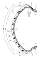
図1は、本実施形態の自動二輪車用タイヤ(以下、単に「タイヤ」ということがある。)1の正規状態におけるタイヤ回転軸(図示省略)を含むタイヤ子午線断面図が示されている。
An embodiment of the present invention will be described below with reference to the drawings.
FIG. 1 is a sectional view of a tire meridian including a tire rotation axis (not shown) in a normal state of a motorcycle tire (hereinafter, simply referred to as “tire”) 1 of the present embodiment.
前記「正規状態」は、タイヤ1が正規リム(図示省略)にリム組みされ、かつ、正規内圧が充填され、しかも無負荷の状態である。本明細書では特に断りがない限り、タイヤ1の各部の寸法は、正規状態で測定された値である。 The "regular state" is a state in which the tire 1 is assembled on a regular rim (not shown), is filled with a regular internal pressure, and is unloaded. In the present specification, unless otherwise specified, the dimensions of each part of the tire 1 are values measured in a normal state.
前記「正規リム」は、タイヤ1が基づいている規格を含む規格体系において、当該規格がタイヤ毎に定めているリムであり、例えばJATMAであれば "標準リム" 、TRAであれば "Design Rim" 、ETRTOであれば "Measuring Rim" である。 The "regular rim" is a rim that is defined for each tire in the standard system including the standard on which the tire 1 is based. For example, "standard rim" for JATMA and "Design Rim" for TRA. ", ETRTO is "Measuring Rim".
前記「正規内圧」は、タイヤ1が基づいている規格を含む規格体系において、各規格がタイヤ毎に定めている空気圧であり、JATMAであれば "最高空気圧" 、TRAであれば表 "TIRE LOAD LIMITS AT VARIOUS COLD INFLATION PRESSURES" に記載の最大値、ETRTOであれば "INFLATION PRESSURE" である。 The "regular internal pressure" is the air pressure that each standard defines for each tire in the standard system including the standard on which the tire 1 is based. For JATMA, "maximum air pressure", and for TRA, the table "TIRE LOAD" LIMITS AT VARIOUS COLD INFLATION PRESSURES "Maximum value, ETRTO is "INFLATION PRESSURE".
図1に示されるように、本実施形態のタイヤ1は、路面と接地する踏面2aを有するトレッド部2と、トロイド状のカーカス6と、カーカス6のタイヤ半径方向外側かつトレッド部2の内部に配されたトレッド補強層7とを有している。
As shown in FIG. 1, a tire 1 of the present embodiment has a tread portion 2 having a
トレッド部2は、タイヤ半径方向外側に凸の円弧状に湾曲しており、一対のトレッド端TE、TEを有している。トレッド端TEは、タイヤ1のタイヤ軸方向の最も外側に位置している。本実施形態のトレッド部2は、タイヤ赤道Cを含むクラウン領域2Cと、その両外側の一対のショルダー領域2Sとを含んでいる。本実施形態のクラウン領域2Cは、正規状態のタイヤ1に正規荷重を負荷してキャンバー角0度で接地させた直進接地領域内に位置している。ショルダー領域2Sは、クラウン領域2Cのタイヤ軸方向の端部からトレッド端TEまでの範囲である。
The tread portion 2 is curved in an arc shape that is convex outward in the radial direction of the tire, and has a pair of tread ends TE and TE. The tread end TE is located on the outermost side in the tire axial direction of the tire 1. The tread portion 2 of the present embodiment includes a
前記「正規荷重」とは、タイヤ1が基づいている規格を含む規格体系において、各規格がタイヤ毎に定めている荷重であり、JATMAであれば"最大負荷能力"、TRAであれば表 "TIRE LOAD LIMITS AT VARIOUS COLD INFLATION PRESSURES" に記載の最大値、ETRTOであれば "LOAD CAPACITY" である。 The "regular load" is the load that each standard defines for each tire in the standard system including the standard on which the tire 1 is based. In the case of JATMA, it is the "maximum load capacity", and in the case of TRA it is the table " Maximum value described in "TIRE LOAD LIMITS AT VARIOUS COLD INFLATION PRESSURES", and "LOAD CAPACITY" for ETRTO.
カーカス6は、例えば、少なくとも1枚のカーカスプライ6Aにより形成されている。カーカスプライ6Aは、例えば、タイヤ赤道Cに対して75〜90°の角度で傾けて配列されたカーカスコードを未加硫のトッピングゴムにより被覆して形成されている。カーカスプライ6Aは、例えば、トレッド部2からサイドウォール部3を経て両側のビード部4、4のビードコア5に至る本体部6aと、本体部6aに連なる1対の折り返し部6bとを含んでいる。
The
トレッド補強層7は、タイヤ子午線断面において、トレッド部2に沿って湾曲にのびており、トレッド部2のほぼ全幅にわたって形成されている。これにより、トレッド補強層7は、トレッド部2の剛性をトレッド部2の全域にわたって高めることができる。このような観点より、トレッド補強層7のトレッド部2の踏面2aに沿った幅Wtは、トレッド端TE、TE間のトレッド部2の踏面2aに沿った幅(以下、単に「トレッド展開幅」という場合がある。)TWの80%〜95%であるのが望ましい。
The
本実施形態のトレッド補強層7は、帯状プライ9が、カーカス6に巻き付けられることにより形成されている。
The
図2には、帯状プライ9の斜視図が示されている。図2に示されるように、帯状プライ9は、長手方向に延びる両側縁9s、9sを含み、略矩形状の断面を有している。帯状プライ9の幅W1は、例えば、2.5〜12.0mmの範囲であるのが望ましい。帯状プライ9の厚さt1は、例えば、0.6〜3.0mmの範囲であるのが望ましい。
FIG. 2 shows a perspective view of the
帯状プライ9は、例えば、1本又は複数本の補強コード10をトッピングゴム11により被覆して形成されている。補強コード10は、例えば、スチールコードや有機繊維コードが好適に用いられる。補強コード10は、本実施形態では、側縁9sに沿って延びている。
The belt-shaped
図3には、トレッド補強層7をタイヤ周方向に展開した展開平面図が示されている。図3では、便宜上、帯状プライ9が単線(幅方向の中心線)で描かれている。なお、タイヤ1は、トレッド部2がタイヤ半径方向外側に凸の円弧状に湾曲しているので、タイヤ赤道C側とトレッド端TE側とではタイヤ周長が異なる。しかしながら、図3のトレッド補強層7は、タイヤ周方向に対する角度基準で記載されているので、トレッド補強層7の展開平面図が長方形状で表されている。
FIG. 3 shows a developed plan view in which the
図3に示されるように、トレッド補強層7は、本実施形態では、帯状プライ9がクラウン領域2Cに巻き付けられているクラウン補強部7Cと、帯状プライ9がショルダー領域2Sに巻き付けられている一対のショルダー補強部7S、7Sとを含んでいる。クラウン補強部7Cと一対のショルダー補強部7Sとは、例えば、互いに別々の帯状プライ9で形成される。なお、クラウン補強部7C及び一対のショルダー補強部7Sは、連続する1本の帯状プライ9で形成されても良い。
As shown in FIG. 3, in the present embodiment, the
本実施形態のクラウン補強部7Cは、帯状プライ9が実質的にタイヤ周方向に沿って延びる第1周方向部12を含んで形成されている。このようなクラウン補強部7Cは、主に高速走行となる直進走行時に接地するクラウン領域2Cに大きな拘束力を作用させるので、高速走行での遠心力によるトレッド部2の変形を抑制する。また、このようなクラウン補強部7Cは、クラウン領域2Cのねじり剛性の増加を小さくして低いコーナリングパワーを生じさせるため、例えば、路面のギャップ等による反力や振動を小さくして、接地感を高める。従って、クラウン補強部7Cは、高速安定性能を向上する。本実施形態では、クラウン補強部7Cは、第1周方向部12のみで形成されている。また、本明細書では、前記「実質的にタイヤ周方向に沿って延びる第1周方向部」とは、帯状プライ9が、タイヤ周方向に対して0度の角度θ1で延びる態様は勿論、帯状プライ9がタイヤ周方向に対して8度以下で延びる態様を含む。なお、帯状プライ9のタイヤ周方向に対する角度θ1は、本明細書では、局所的に大きな角度で傾斜する部分を除くために、タイヤ1周分の平均で表される。
7 C of crown reinforcement parts of this embodiment are formed so that the strip|belt-shaped
第1周方向部12のトレッド部2の踏面2aに沿った最大幅Wcは、例えば、トレッド部2の展開幅TWの5%以上が望ましく、10%以上がさらに望ましく、60%以下が望ましく、45%以下がさらに望ましく、30以下がさらに望ましい。
The maximum width Wc along the
本実施形態のショルダー補強部7Sのそれぞれは、帯状プライ9が傾斜する複数の傾斜部13と、帯状プライ9が実質的にタイヤ周方向に沿って延びる複数の周方向部14とを含んでいる。本実施形態では、周方向部14の両端に一対の傾斜部13、13が連なっている。各ショルダー補強部7Sは、最もタイヤ赤道C側の内側端部Eiと、最もトレッド端TE側の外側端部Eeとを有している。
Each of the
傾斜部13のタイヤ周方向に対する角度θ2は、好ましくは2〜10度、より好ましくは3〜6度である。傾斜部13の角度θ2を大きくすることで、タイヤ1に生じるコーナリングパワーを大きくすることができる。とりわけ、キャンバー角が20度以下では、コーナリングパワーを大きくする効果が強く発揮される。周方向部14のタイヤ周方向に対する角度θ3は、傾斜部13の角度θ2よりも小さければよく、好ましくは5度以下、より好ましくは3度以下、さらに好ましくは1度以下である。
The angle θ2 of the
本実施形態の複数の傾斜部13は、タイヤ周方向に対して一方側(図では右上がり)に傾斜する複数の第1傾斜部15、及び、複数の第1傾斜部15とは逆向きに傾斜(図では右下がり)する複数の第2傾斜部16を含んでいる。このような傾斜部13は、主に旋回走行時に接地するショルダー領域2Sのねじり剛性を大きくして、高いコーナリングパワーを生じさせるので、旋回性能を向上する。
The plurality of
複数の傾斜部13は、複数の第1傾斜部15の側縁15sが互いに接触することなく配され、かつ、複数の第2傾斜部16の側縁16sが互いに接触することなく配されている。これにより、ショルダー補強部7Sは、複数の第1傾斜部15と複数の第2傾斜部16とで囲まれた菱形状の複数の空間部17を有する格子状で形成されている。これにより、ショルダー補強部7Sの一部に作用する張力を、互いに交差する帯状プライ9を介して、格子状に形成されている部分全体にわたって分散することができるので、ショルダー領域2Sの剛性が高められて旋回性能が向上する。本明細書では、「菱形状」とは、直線状に延びる第1傾斜部15及び第2傾斜部16で囲まれた形状をいい、厳密な意味での菱形に限定されず、平行四辺形等も含む。また、「直線状」は、トレッド部2が円弧状で形成されるため、厳密な意味での直線に限定されるものではなく、複数の周期を有する波状やジグザグ状を除いて、例えば、円弧状で形成されるものを含む。
The plurality of
本実施形態の複数の周方向部14は、最もタイヤ赤道C側に配され、かつ、複数の第1傾斜部15のタイヤ軸方向の内端15i又は複数の第2傾斜部16のタイヤ軸方向の内端16iに連なってタイヤ周方向に沿って延びる複数の内側周方向部18を含んでいる。このような内側周方向部18は、クラウン領域2Cに近接する部分において、その拘束力を高めるので、高速安定性能を向上する。また、内側周方向部18は、クラウン補強部7Cとショルダー補強部7Sとの境界において、クラウン領域2C及びショルダー領域2Sの剛性の変化を小さくするので、旋回走行時の過渡特性を高めるため、旋回性能を向上する。
The plurality of
本発明では、複数の内側周方向部18のタイヤ周方向の長さLaと複数の空間部17のタイヤ周方向の最大長さL1との比に着目をした。即ち、クラウン領域2Cとショルダー領域2Sとの境界の剛性と、クラウン領域2Cの剛性及びショルダー領域2Sの剛性との差を小さくして、過渡特性をさらに高め、かつ、内側周方向部18によって大きな拘束力を生じさせる。これにより、旋回性能及び高速安定性能が、一層高められることが知見された。本発明では、複数の内側周方向部18のタイヤ周方向の長さLaは、複数の空間部17のタイヤ周方向の最大長さL1の50%〜150%に規定される。本実施形態では、内側周方向部18に最も近い空間部17の最大長さL1が採用される。
In the present invention, attention has been paid to the ratio between the tire circumferential direction length La of the plurality of inner
本実施形態では、内側周方向部18は、第1傾斜部15及び第2傾斜部16の最もタイヤ赤道C側の交差位置とタイヤ軸方向に同じ位置で設けられている。これにより、内側周方向部18のタイヤ周方向の長さLaが空間部17のタイヤ周方向の最大長さL1の100%で形成されている。
In the present embodiment, the inner
複数の内側周方向部18のタイヤ周方向の長さLaが複数の空間部17のタイヤ周方向の最大長さL1の50%未満の場合、例えば、内側周方向部18の配される部分が小さくなり、くぎや岩等によるパンクの可能性が高くなるおそれも考えられる。複数の内側周方向部18のタイヤ周方向の長さLaが複数の空間部17のタイヤ周方向の最大長さL1の150%を超える場合、例えば、内側周方向部18がタイヤ半径方向に重なる部分が生じる。これにより、ユニフォミティが悪化して高速安定性能が低下するおそれも考えられる。
When the length La of the plurality of inner
図4(a)は、内側周方向部18のタイヤ周方向の長さLaが空間部17のタイヤ周方向の最大長さL1よりも小さく形成されたショルダー補強部7Sを示す平面図である。このショルダー補強部7Sは、複数の内側周方向部18が、内側端部Ei上で、タイヤ周方向に並ぶ複数の隙間20とともにタイヤ周方向に連なっている。また、内側周方向部18は、第1傾斜部15及び第2傾斜部16の最もタイヤ赤道C側の交差位置とタイヤ軸方向に位置ずれして設けられている。図4(b)は、内側周方向部18のタイヤ周方向の長さLaが空間部17のタイヤ周方向の最大長さL1よりも大きいショルダー補強部7Sを示す平面図である。このショルダー補強部7Sも、複数の内側周方向部18が、内側端部Ei上で、タイヤ周方向に並ぶ複数の隙間20とともにタイヤ周方向に連なっている。
FIG. 4A is a plan view showing the
図5は、ショルダー補強部7Sとクラウン補強部7Cとの境界の拡大図である。図5に示されるように、タイヤ軸方向距離Waは、タイヤ軸方向距離Wbの500%よりも小さいのが望ましい。タイヤ軸方向距離Waは、内側周方向部18の最もタイヤ赤道C側に配された補強コード10aと、この補強コード10aとタイヤ軸方向で隣り合うクラウン補強部7Cの補強コード10bとの間の距離である。タイヤ軸方向距離Wbは、クラウン補強部7Cのタイヤ軸方向に隣り合う補強コード10、10間の距離である。前記距離Waが前記距離Wbの500%以上の場合、内側周方向部18が配される部分の剛性とクラウン補強部7Cの剛性との差の変化が大きくなり、旋回走行の初期において、過渡特性が悪化するおそれがある。また、前記距離Waが前記距離Wbの500%以上の場合、補強コード10の密度が小さくなりくぎや岩等によるパンクの可能性が高くなるおそれがある。タイヤ軸方向距離Waがタイヤ軸方向距離Wbよりも過度に小さい場合、ショルダー補強部7Sとクラウン補強部7Cとの間の剛性が大きくなり過ぎ、過渡特性が低下するおそれがある。このため、前記距離Waは前記距離Wbの50%以上が望ましい。
FIG. 5 is an enlarged view of the boundary between the
特に限定されるものではないが、ショルダー補強部7Sのタイヤ軸方向に隣り合う補強コード10、10間のタイヤ軸方向距離Wdは、前記タイヤ軸方向距離Wbの70%〜130%が望ましい。
Although not particularly limited, the tire axial distance Wd between the reinforcing
クラウン補強部7Cは、本実施形態では、帯状プライ9が螺旋状に巻き重ねられたジョイントレス構造であるのが望ましい。クラウン補強部7Cは、本実施形態では、帯状プライ9がタイヤ周方向に複数周、巻き付けられている。これにより、高速安定性能がさらに高められる。
In the present embodiment, the
クラウン補強部7Cを形成する帯状プライ9は、補強コード10が1本であるのが望ましい。これにより、クラウン領域2Cのねじり剛性が高められるので、高いねじり剛性を有するショルダー領域2Sとのねじり剛性の差が小さくなり、さらに過渡特性が向上する。このような補強コード10が1本である帯状プライ9は、その幅W1が、例えば、2.5〜3.5mm、厚さt1は、例えば、0.6〜3.0mmの範囲であるのが望ましい。
The strip-shaped
図3に示されるように、ショルダー補強部7Sの周方向部14は、本実施形態では、さらに、最もタイヤ軸方向外側に配されてタイヤ周方向に沿って延びる複数の外側周方向部19を含んでいる。外側周方向部19は、本実施形態では、複数の第1傾斜部15のタイヤ軸方向の外端15e又は複数の第2傾斜部16のタイヤ軸方向の外端16eに連なっている。このような外側周方向部19は、例えば、第1傾斜部15と第2傾斜部16とが直接連なる場合に比して、帯状プライ9の補強コード10に作用する曲げ応力を低減できる。また、外側周方向部19は、トレッド補強層7の外端7e側で小さいコーナリングパワーを生じさせて、反力や振動を小さくする。これにより、フルバンク走行時での接地感を高めて、旋回性能をさらに向上する。外側周方向部19は、内側周方向部18と同じ形状で形成されるのが望ましい。
As shown in FIG. 3, in the present embodiment, the
本実施形態では、複数の内側周方向部18によって、タイヤ周方向に連続して1周分延びる仮想の周方向連続部14xが形成されている。また、本実施形態では、複数の外側周方向部19によって、タイヤ周方向に連続して1周分延びる仮想の周方向連続部14yが形成されている。このような内側周方向部18及び外側周方向部19は、過渡特性及びフルバンク走行時の接地感を高め、一層、旋回性能を向上する。
In the present embodiment, the plurality of inner
次に、このようなタイヤ1の製造方法が説明される。本実施形態のタイヤ1は、生タイヤを形成する工程と、生タイヤを加硫成形する工程とを含んで製造される。生タイヤを形成する工程は、上述のトレッド補強層7を形成するためのトレッド補強層形成工程を含んでいる。トレッド補強層形成工程は、長尺の帯状プライ9を巻き付ける、巻付け工程を含んでいる。なお、トレッド補強層形成工程の巻付け工程を除く生タイヤを形成する工程、及び、生タイヤを加硫成形する工程は、周知の工程が採用されるので、その説明が省略される。
Next, a method for manufacturing such a tire 1 will be described. The tire 1 of the present embodiment is manufactured by including a step of forming a raw tire and a step of vulcanizing and molding the raw tire. The step of forming a green tire includes a tread reinforcing layer forming step for forming the
本実施形態の巻付け工程では、クラウン領域2C及び各ショルダー領域2S、2Sのそれぞれが、異なる1本の帯状プライ9で巻き付けられる。即ち、巻き付け工程は、クラウン補強部7Cを形成するクラウン巻付け工程、一方のショルダー補強部7Sを形成する第1ショルダー巻付け工程、及び、他方のショルダー補強部7Sを形成する第2ショルダー巻付け工程を含み、異なる帯状プライ9で形成される。本実施形態の巻き付け工程は、第1ショルダー巻付け工程、クラウン巻付け工程及び第2ショルダー巻付け工程の順で行われる。しかしながら、巻き付け工程は、このような態様に限定されるものではなく、例えば、クラウン巻付け工程や第2ショルダー巻付け工程から始められても良い。
In the winding step of the present embodiment, each of the
図6は、巻付け工程を概念的に示す模式図である。図6に示されるように、巻付け工程は、プロファイルデッキ31の外周面31aに、長尺の帯状プライ9を、直接又はカーカスプライ6Aを介して巻き付けている。
FIG. 6 is a schematic diagram conceptually showing the winding step. As shown in FIG. 6, in the winding step, the long strip-shaped
本実施形態のプロファイルデッキ31は、半径方向外側に凸の円弧状に湾曲する外周面31aを有する周知構造の回転体である。プロファイルデッキ31は、例えば、セグメント状の複数の部材からなり、プロファイルデッキ31の内部に収容された膨張体35を半径方向に移動させることにより、外周面31aが拡縮径可能に構成されている。
The
プロファイルデッキ31の両側には、例えば、周知構造の一対のカーカス保持装置36が配置されている。カーカス保持装置36は、軸方向に移動可能なリング状部材であり、支持軸37に装着されて、プロファイルデッキ31と同心かつ一体的に回転することができる。カーカス保持装置36は、ビードコア5とともに円筒状のカーカスプライ6Aを保持することができる。
On both sides of the
帯状プライ9は、例えば、周知のアプリケータ34によって、連続的にプロファイルデッキ31へと供給される。アプリケータ34は、例えば、周知の3次元移動装置(図示省略)等によって、プロファイルデッキ31の外周面31aに沿って、円弧状に往復動される。これにより、帯状プライ9は、外周面31a上に正確に巻き付けられる。
The strip ply 9 is continuously supplied to the
本実施形態の第1ショルダー巻付け工程では、カーカスプライ6Aの上に、帯状プライ9の巻き付けが開始される。図7は、本実施形態の第1ショルダー巻付け工程を概念的に説明する平面図である。図7(a)は、帯状プライ9の巻き付けが開始された直後のショルダー補強部7Sの形成状態を示す平面図である。なお、図7(a)では、巻き付けられていない帯状プライ9が仮想線で示され、巻き付け途中の帯状プライ9が符号9fで示されている。図7(b)は、図7(a)よりも帯状プライ9の巻き付けが進んだショルダー補強部7Sの形成状態を示す平面図である。図7(b)では、巻き付け途中の帯状プライ9が符号9hで示している。
In the first shoulder winding step of this embodiment, the winding of the belt-shaped
図7(a)に示されるように、第1ショルダー巻付け工程は、先ず、例えば、ショルダー補強部7Sの内側端部Eiに、帯状プライ9の巻き付け開始時の巻き付け始端9dを固定する。なお、巻き付け始端9dは、ショルダー補強部7Sの外側端部Eeや傾斜部13中に固定されてもよい。第1ショルダー巻付け工程で巻き付けられる帯状プライ9は、補強コード10が複数本、例えば、3本で形成されている。
As shown in FIG. 7A, in the first shoulder winding step, first, for example, the winding
その後、第1ショルダー巻付け工程は、アプリケータ34により、帯状プライ9を、内側端部Eiと、外側端部Eeとの間を往復移動させながら回転しているプロファイルデッキ31の外周面31aに供給する。この工程では、図7に示されるように、帯状プライ9を、第1傾斜部15と、第2傾斜部16とを含むジグザグ状に巻き付けるとともに、帯状プライ9の側縁9s(図2に示す)が互いに接触しないように巻き付ける。
Thereafter, in the first shoulder winding step, the
本実施形態の第1ショルダー巻付け工程は、第1傾斜部15、外側周方向部19、第2傾斜部16、内側周方向部18及び第1傾斜部15…の順に形成するように巻き付けられる。即ち、本実施形態では、内側周方向部18の一端には、第1傾斜部15が連なり、内側周方向部18の他端には、第2傾斜部16が連なる。また、外側周方向部19の一端には、第2傾斜部16が連なり、外側周方向部19の他端には、第1傾斜部15が連なる。この工程により、帯状プライ9は、第1傾斜部15と第2傾斜部16とで囲まれた菱形状の空間部17を有する格子状に形成され得る。
In the first shoulder winding step of this embodiment, the first
第1ショルダー巻付け工程は、本実施形態では、内側周方向部18の一端と、この内側周方向部18とタイヤ周方向で隣接する内側周方向部18の他端とがタイヤ周方向で連なって形成されている。これにより、クラウン補強部7Cとショルダー補強部7Sとの境界の部分の拘束力をさらに高めて、高速安定性能を、一層高める。また、本実施形態では、外側周方向部19の一端と、この外側周方向部19とタイヤ周方向で隣接する外側周方向部19の他端とがタイヤ周方向で連なって形成されている。なお、第1ショルダー巻付け工程は、このような態様に限定されるものではなく、例えば、内側周方向部18の一端と、この内側周方向部18とタイヤ周方向で隣接する内側周方向部18の他端とがタイヤ周方向に離間して形成されていても良い(図示省略)。また、例えば、内側周方向部18の一端と、この内側周方向部18とタイヤ周方向で隣接する内側周方向部18の他端とがタイヤ半径方向で重なって形成されていても良い(図示省略)。
In the first shoulder winding step, in the present embodiment, one end of the inner
第1ショルダー巻付け工程では、帯状プライ9の巻き付け終了時の巻き付け終端9eが巻き付け始端9dにタイヤ周方向で連なって固定されるのが望ましい。
In the first shoulder winding step, it is desirable that the winding
内側周方向部18は、本実施形態では、第1傾斜部15及び第2傾斜部16と角部を形成されるように直線状に連なっている。なお、外側周方向部19も、例えば、第1傾斜部15及び第2傾斜部16と角部を形成されるように直線状に連なっていても良い。
In this embodiment, the inner
次に、例えば、クラウン巻付け工程が行われる。クラウン巻付け工程は、本実施形態では、第1ショルダー巻付け工程とは異なる1本の帯状プライ9を用いて行われる。クラウン巻き付け工程で巻き付けられる帯状プライ9は、補強コード10が1本で形成されている。
Next, for example, a crown winding step is performed. In the present embodiment, the crown winding step is performed using one strip-shaped
本実施形態のクラウン巻付け工程は、アプリケータ34により、帯状プライ9を、クラウン補強部7Cのタイヤ軸方向の一端側から他端側に向けて1周以上、螺旋状に巻き付ける。なお、クラウン巻付け工程は、帯状プライ9を、クラウン補強部7Cのタイヤ軸方向の他端側から一端側に向けて螺旋状に巻き付けても構わない。クラウン巻付け工程では、帯状プライ9の巻付け始端と巻付け終端とをタイヤ周方向で略等しい位置とするのが望ましい。
In the crown winding step of the present embodiment, the
次に、第2ショルダー巻付け工程が行われる。第2ショルダー巻付け工程は、本実施形態では、クラウン巻付け工程とは異なる1本の帯状プライ9を用いて行われる。なお、第2ショルダー巻付け工程は、第1ショルダー巻付け工程と同様に行われるので、その詳細な説明が省略される。このようにして、トレッド補強層7が形成される。
Next, the second shoulder winding step is performed. In the present embodiment, the second shoulder winding step is performed using one band-shaped
図8は、他の実施形態の第1ショルダー巻付け工程又は第2ショルダー巻付け工程を概念的に示す模式図である。図8(a)は、帯状プライ9の巻き付けが開始された直後のショルダー補強部7Sの形成状態を示す平面図である。なお、図8(a)では、巻き付けられていない帯状プライ9が仮想線で、巻き付け途中の帯状プライ9が符号9fで示されている。図8(b)は、図8(a)よりも帯状プライ9の巻き付けが進んだショルダー補強部7Sの形成状態を示す平面図である。図8(b)では、巻き付け途中の帯状プライ9が符号9hで示されている。図8(b)には、帯状プライ9の巻き付け順が仮想線で示され、仮想線a、b、c及びdの順で巻き付けられる。図7の実施形態と同じ構成は、同じ符号が付され、その説明が省略される。また、この実施形態でも、第2ショルダー巻付け工程は、第1ショルダー巻付け工程と同様となるので、その詳細な説明が省略される。この実施形態の第1ショルダー巻き付け工程では、先ず、ショルダー補強部7Sの外側端部Eeに、帯状プライ9の巻き付け開始時の巻き付け始端9dが固定される。なお、巻き付け始端9dは、ショルダー補強部7Sの内側端部Eiや傾斜部13中に固定されてもよい。
FIG. 8 is a schematic view conceptually showing the first shoulder winding step or the second shoulder winding step of another embodiment. FIG. 8A is a plan view showing the formation state of the
次に、アプリケータ34により、帯状プライ9を、内側端部Eiと、外側端部Eeとの間を往復移動させながら回転しているプロファイルデッキ31の外周面31aに供給する。この工程では、図8(a)に示されるように、先ず、帯状プライ9を、第1傾斜部15、内側周方向部18、第1傾斜部15、外側周方向部19、第1傾斜部15…の順で巻き付ける。次に、図8(b)に示されるように、帯状プライ9を、第2傾斜部16、内側周方向部18、第2傾斜部16、外側周方向部19、第2傾斜部16…の順で巻き付ける。即ち、本実施形態では、ショルダー補強部7Sは、内側周方向部18の両端には、タイヤ周方向に隣接する一対の第1傾斜部15、15が連なるか、又は、タイヤ周方向に隣接する一対の第2傾斜部16、16が連なって形成される。
Next, the
そして、複数の第1傾斜部15の側縁15sが互いに接触することなく配され、かつ、複数の第2傾斜部16の側縁16sが互いに接触することなく配される。これにより、ショルダー補強部7Sは、複数の第1傾斜部15と複数の第2傾斜部16とで囲まれた菱形状の複数の空間部17を有する格子状となる。
Then, the side edges 15s of the plurality of first
図9(a)は、第1傾斜部15、第2傾斜部16及び内側周方向部18の他の実施形態の接続態様を示す平面図である。この実施形態では、内側周方向部18は、円弧状となる円弧状部18yを含んでいる。この実施形態では、円弧状部18yと第1傾斜部15及び第2傾斜部16とが滑らかに連なって形成されている。この実施形態では、内側周方向部18は、円弧状部18yのみで形成されている。内側周方向部18は、タイヤ周方向に対する角度θ3が5度以下で形成されている。なお、外側周方向部19も、円弧状部(図示省略)によって第1傾斜部15及び第2傾斜部16と滑らかに連なって形成されても良い。これにより、帯状プライ9の補強コード10に作用する曲げ応力が小さくなるので、旋回性能が向上する。
FIG. 9A is a plan view showing a connection mode of another embodiment of the first
図9(b)は、第1傾斜部15と内側周方向部18との他の実施形態の接続態様を示す平面図である。この実施形態では、第1傾斜部15は、タイヤ周方向に対して2度以上の角度θ2で略直線状に延びる主部15xと、主部15xに滑らかに連なりかつ円弧状に延びる円弧状部15yとを含んでいる。内側周方向部18は、タイヤ周方向に沿って5度以下の角度θ3で略直線状に延びる主部18xと、主部18xに滑らかに連なりかつ円弧状に延びる円弧状部18yとを含んでいる。第1傾斜部15の主部15xと内側周方向部18の主部18xとは、これら円弧状部15y及び円弧状部18yを介して滑らかに連なっている。なお、このような接続態様は、第1傾斜部15と外側周方向部19との接続態様、第2傾斜部16と内側周方向部18との接続態様、及び、第2傾斜部16と外側周方向部19との接続態様に用いられても良いのはいうまでもない(図示省略)。
FIG. 9B is a plan view showing a connection mode of the first
また、ショルダー補強部7Sのそれぞれは、例えば複数本の帯状プライ9を巻き付けて形成されても良い(図示省略)。
Further, each of the
以上、本発明の特に好ましい実施形態について詳述したが、本発明は図示の実施形態に限定されることなく、種々の態様に変形して実施し得る。 Although a particularly preferred embodiment of the present invention has been described above in detail, the present invention is not limited to the illustrated embodiment and can be modified and implemented in various modes.
図1に示す基本構造及び図3に示すトレッド補強層を有する自動二輪車用タイヤが、表1の仕様に基づいて試作された。これらのタイヤについて、高速安定性能、旋回性能、旋回力及び耐パンク性能が評価された。各タイヤの共通仕様やテスト方法は、以下の通りである。従来例のタイヤのトレッド補強層は、菱形状の空間部を有することなく、トレッド補強層のタイヤ軸方向の両端間を連続して螺旋状に延びる周方向部のみで形成されている。
帯状プライ(ショルダー補強部):幅4.0mm、厚さ1.0mm、補強コード3本
帯状プライ(クラウン補強部):幅2.5mm、厚さ1.0mm、補強コード1本
トレッド補強層の幅(Wt/TW):90%
第1周方向部の最大幅(Wc/TW):12%
A motorcycle tire having the basic structure shown in FIG. 1 and the tread reinforcing layer shown in FIG. 3 was prototyped based on the specifications of Table 1. These tires were evaluated for high speed stability, turning performance, turning force and puncture resistance. The common specifications and test methods for each tire are as follows. The tread reinforcing layer of the tire according to the conventional example does not have a rhombic space portion, and is formed only by the circumferential portion continuously extending spirally between both ends in the tire axial direction of the tread reinforcing layer.
Band-shaped ply (shoulder reinforcement part): width 4.0 mm, thickness 1.0 mm, three reinforcing cords Band-shaped ply (crown reinforcement part): width 2.5 mm, thickness 1.0 mm, one reinforcing cord Tread reinforcement layer Width (Wt/TW): 90%
Maximum width of the first circumferential direction part (Wc/TW): 12%
<高速安定性能・旋回性能>
各試供タイヤが、下記の条件で、排気量130ccの自動二輪車の全輪に装着された。テストライダーは、上記車両を乾燥アスファルト路面のテストコースを走行させた。このときの各試供タイヤのハンドル安定性、グリップ等に関する高速走行特性、及び、旋回走行の過渡特性、ハンドル操作性等に関する旋回走行特性がテストライダーの官能により評価された。結果は、比較例1を100とする評点で表示されている。数値が大きいほど良好である。
タイヤサイズ:120/70ZR17(前輪) 190/55ZR17(後輪)
リム:17M/CxMT3.50(前輪)/17M/CxMT5.50(後輪)
内圧(全輪):250kPa
<High-speed stability and turning performance>
Each sample tire was mounted on all wheels of a motorcycle with a displacement of 130cc under the following conditions. The test rider ran the above vehicle on a test course on a dry asphalt surface. At this time, the test rider's sensory evaluation evaluated the steering wheel stability of each sample tire, high-speed running characteristics such as grip, and the transient characteristics of turning running, and turning characteristics such as steering wheel operability. The results are displayed as a score with Comparative Example 1 as 100. The larger the value, the better.
Tire size: 120/70ZR17 (front wheel) 190/55ZR17 (rear wheel)
Rim: 17M/CxMT3.50 (front wheel)/17M/CxMT5.50 (rear wheel)
Internal pressure (all wheels): 250kPa
<旋回力(コーナリングパワー)>
各試供タイヤを、下記条件下で、室内試験器を用いてコーナリングフォースを測定してコーナリングパワーを求めた。結果は、比較例1の値を100とする指数によって表示されている。数値が大きいほどコーナリングパワーが高く、良好である。コーナリングパワーは、スリップ角+1゜の時のコーナリングフォース値CF(+1゜)から、スリップ角−1゜の時のコーナリングフォース値CF(−1゜)を引いた値を2で割って得た次式で示すスリップ角1度当たりのコーナリングフォースである。
{CF(+1゜)−CF(−1゜)}/2
タイヤサイズ:190/55ZR17
内圧:200kPa
荷重:1.3kN
速度:30km/h
<Turning force (cornering power)>
The cornering force of each test tire was measured using an indoor tester under the following conditions to determine the cornering power. The results are displayed by an index with the value of Comparative Example 1 being 100. The larger the value, the higher the cornering power and the better. The cornering power was obtained by dividing the value obtained by subtracting the cornering force value CF(-1°) at the slip angle -1° from the cornering force value CF(+1°) at the slip angle +1° by 2 It is the cornering force per slip angle shown by the formula.
{CF(+1°)-CF(-1°)}/2
Tire size: 190/55ZR17
Internal pressure: 200kPa
Load: 1.3kN
Speed: 30km/h
<耐パンク性能>
各供試タイヤが、日本工業規格JIS K6366に準じたプランジャー試験によりテストされた。結果は、比較例1の破壊エネルギーの値を100とする指数で示され、数値が大きい程良好であることを示す。
テストの結果は、表1に示される。
<Puncture resistance>
Each test tire was tested by a plunger test according to Japanese Industrial Standard JIS K6366. The results are shown as an index with the breaking energy value of Comparative Example 1 being 100, and the larger the value, the better.
The test results are shown in Table 1.

テストの結果、各実施例のタイヤは、比較例のタイヤに対し、バランスよく優れていることが確認された。 As a result of the test, it was confirmed that the tires of Examples were excellent in balance with the tires of Comparative Example.
1 自動二輪車用タイヤ
2 トレッド部
7Sショルダー補強部
9 帯状プライ
13 傾斜部
14 周方向部
15 第1傾斜部
16 第2傾斜部
17 空間部
18 内側周方向部
DESCRIPTION OF SYMBOLS 1 Motorcycle tire 2
Claims (5)
前記トレッド補強層は、1本又は複数本の補強コードがトッピングゴムにより被覆された長尺の帯状プライが、タイヤ赤道を含むクラウン領域に巻き付けられているクラウン補強部と、前記帯状プライが、前記クラウン領域の両外側のショルダー領域に巻き付けられている一対のショルダー補強部とを含み、
前記クラウン補強部は、前記帯状プライが実質的にタイヤ周方向に沿って延びる第1周方向部を含み、
前記一対のショルダー補強部のそれぞれは、前記帯状プライが傾斜する複数の傾斜部と、前記帯状プライが実質的にタイヤ周方向に沿って延びる複数の周方向部とを含み、
前記複数の傾斜部は、タイヤ周方向に対して一方側に傾斜する複数の第1傾斜部、及び、前記複数の第1傾斜部とは逆向きに傾斜する複数の第2傾斜部を含み、
前記複数の第1傾斜部の側縁が互いに接触することなく配され、かつ、前記複数の第2傾斜部の側縁が互いに接触することなく配されることにより、前記複数の第1傾斜部と前記複数の第2傾斜部とで囲まれた菱形状の複数の空間部を有する格子状であり、
前記複数の周方向部は、最もタイヤ赤道側に配され、かつ、前記複数の第1傾斜部又は前記複数の第2傾斜部のタイヤ軸方向の内端に連なってタイヤ周方向に沿って延びる複数の内側周方向部を含み、
前記複数の内側周方向部のタイヤ周方向の長さは、前記複数の空間部のタイヤ周方向の最大長さの50%〜150%であり、
前記複数の内側周方向部の両端には、前記複数の第1傾斜部のいずれか一つ、及び、前記複数の第1傾斜部のいずれか一つとタイヤ周方向で隣接する前記第2傾斜部が連なり、
前記複数の内側周方向部のタイヤ周方向の長さは、それぞれ均一である、
自動二輪車用タイヤ。 A toroidal carcass, and a motorcycle tire having a tread reinforcing layer arranged inside the tire tread portion in the tire radial direction outside of the carcass,
The tread reinforcing layer is a long strip ply in which one or a plurality of reinforcing cords are covered with topping rubber, a crown reinforcing portion wound around a crown region including a tire equator, and the strip ply, Including a pair of shoulder reinforcements wound around the shoulder regions on both outer sides of the crown region,
The crown reinforcing portion includes a first circumferential portion in which the strip-shaped ply extends substantially along the tire circumferential direction,
Each of the pair of shoulder reinforcing portions includes a plurality of inclined portions in which the strip-shaped ply is inclined, and a plurality of circumferential portions in which the strip-shaped ply extends substantially along the tire circumferential direction,
The plurality of inclined portions include a plurality of first inclined portions that are inclined to one side with respect to the tire circumferential direction, and a plurality of second inclined portions that are inclined in an opposite direction to the plurality of first inclined portions,
Since the side edges of the plurality of first inclined portions are arranged without contacting each other and the side edges of the plurality of second inclined portions are arranged without contacting each other, the plurality of first inclined portions are arranged. And a lattice shape having a plurality of diamond-shaped space portions surrounded by the plurality of second inclined portions,
The plurality of circumferential portions are arranged closest to the tire equator, and extend along the tire circumferential direction continuously with the inner ends of the plurality of first inclined portions or the plurality of second inclined portions in the tire axial direction. Including a plurality of inner circumferential portions,
Tire circumferential direction of the length of the plurality of inner circumferential portion, Ri 50% to 150% der in the tire circumferential direction of the maximum length of the plurality of spaces,
At both ends of the plurality of inner circumferential portions, any one of the plurality of first inclined portions and the second inclined portion that is adjacent to any one of the plurality of first inclined portions in the tire circumferential direction. Are connected,
The tire circumferential lengths of the plurality of inner circumferential portions are each uniform.
Motorcycle tires.
前記複数の内側周方向部のそれぞれの最もタイヤ赤道側に配された前記補強コードと、前記複数の内側周方向部のそれぞれの最もタイヤ赤道側に配された前記補強コードとタイヤ軸方向で隣り合う前記クラウン補強部の前記補強コードとの間のタイヤ軸方向距離は、前記クラウン補強部のタイヤ軸方向に隣り合う前記補強コード間のタイヤ軸方向距離の500%よりも小さい、請求項1記載の自動二輪車用タイヤ。 The crown reinforcing portion, the strip-shaped ply is wound a plurality of times in the tire circumferential direction,
The reinforcement cords arranged on the most tire equator side of each of the plurality of inner circumferential portions, and the reinforcement cords arranged on the most tire equator side of each of the plurality of inner circumferential portions adjacent to each other in the tire axial direction. The tire axial direction distance between the reinforcing cords of the matching crown reinforcing portion is smaller than 500% of the tire axial direction distance between the reinforcing cords adjacent to each other in the tire axial direction of the crown reinforcing portion. Motorcycle tires from.
Priority Applications (2)
| Application Number | Priority Date | Filing Date | Title |
|---|---|---|---|
| JP2018012944A JP6741032B2 (en) | 2018-01-29 | 2018-01-29 | Motorcycle tires |
| EP18212547.6A EP3517319B1 (en) | 2018-01-29 | 2018-12-14 | Motorcycle tire |
Applications Claiming Priority (1)
| Application Number | Priority Date | Filing Date | Title |
|---|---|---|---|
| JP2018012944A JP6741032B2 (en) | 2018-01-29 | 2018-01-29 | Motorcycle tires |
Publications (2)
| Publication Number | Publication Date |
|---|---|
| JP2019130950A JP2019130950A (en) | 2019-08-08 |
| JP6741032B2 true JP6741032B2 (en) | 2020-08-19 |
Family
ID=64665538
Family Applications (1)
| Application Number | Title | Priority Date | Filing Date |
|---|---|---|---|
| JP2018012944A Active JP6741032B2 (en) | 2018-01-29 | 2018-01-29 | Motorcycle tires |
Country Status (2)
| Country | Link |
|---|---|
| EP (1) | EP3517319B1 (en) |
| JP (1) | JP6741032B2 (en) |
Families Citing this family (1)
| Publication number | Priority date | Publication date | Assignee | Title |
|---|---|---|---|---|
| JP6720989B2 (en) * | 2018-02-02 | 2020-07-08 | 住友ゴム工業株式会社 | Motorcycle tires |
Family Cites Families (8)
| Publication number | Priority date | Publication date | Assignee | Title |
|---|---|---|---|---|
| JP3053287B2 (en) * | 1991-12-26 | 2000-06-19 | 住友ゴム工業株式会社 | Radial tires for motorcycles |
| JP4810384B2 (en) * | 2006-09-29 | 2011-11-09 | 株式会社ブリヂストン | Pneumatic tire |
| JP2012179850A (en) * | 2011-03-02 | 2012-09-20 | Bridgestone Corp | Method for forming belt layer material, and method for manufacturing pneumatic tire |
| JP5918742B2 (en) * | 2013-12-03 | 2016-05-18 | 住友ゴム工業株式会社 | Manufacturing method of pneumatic tire for motorcycle |
| JP6249525B2 (en) * | 2014-03-17 | 2017-12-20 | 住友ゴム工業株式会社 | Pneumatic tire for motorcycles |
| JP6450215B2 (en) * | 2015-02-23 | 2019-01-09 | 住友ゴム工業株式会社 | Method for manufacturing motorcycle tire |
| JP6506612B2 (en) * | 2015-05-11 | 2019-04-24 | 住友ゴム工業株式会社 | Motorcycle tire and method of manufacturing motorcycle tire |
| JP6786839B2 (en) * | 2016-03-28 | 2020-11-18 | 住友ゴム工業株式会社 | Pneumatic tires |
-
2018
- 2018-01-29 JP JP2018012944A patent/JP6741032B2/en active Active
- 2018-12-14 EP EP18212547.6A patent/EP3517319B1/en active Active
Also Published As
| Publication number | Publication date |
|---|---|
| JP2019130950A (en) | 2019-08-08 |
| EP3517319A1 (en) | 2019-07-31 |
| EP3517319B1 (en) | 2020-10-28 |
Similar Documents
| Publication | Publication Date | Title |
|---|---|---|
| JP6907820B2 (en) | Motorcycle tires | |
| JP5412503B2 (en) | Motorcycle tires | |
| JP6946646B2 (en) | Motorcycle tires | |
| JP6862775B2 (en) | Pneumatic tires for motorcycles | |
| JP2008162354A (en) | Tire for motorcycle | |
| JP5770847B2 (en) | Pneumatic tires for motorcycles | |
| JP2003237315A (en) | Pneumatic radial tire, and method for manufacturing the same | |
| JP6458120B2 (en) | Pneumatic tires for motorcycles | |
| JP6741032B2 (en) | Motorcycle tires | |
| JP6981283B2 (en) | Motorcycle tires | |
| JP6720989B2 (en) | Motorcycle tires | |
| JP4891604B2 (en) | Pneumatic tire | |
| JP4456380B2 (en) | Motorcycle tires | |
| JP6750639B2 (en) | Pneumatic tire | |
| JP2733428B2 (en) | Pneumatic tire | |
| JP6851924B2 (en) | Pneumatic tires for motorcycles | |
| JP7040123B2 (en) | tire | |
| JP4755334B2 (en) | Manufacturing method of radial tire for motorcycle | |
| JP7000890B2 (en) | tire | |
| JP2001138707A (en) | Pneumatic tire | |
| JP2014226945A (en) | Pneumatic tire | |
| JP6729617B2 (en) | tire | |
| JP2005247061A (en) | Tire for motorcycle | |
| JP2012001057A (en) | Tire for motorcycle | |
| JP2008120349A (en) | Pneumatic radial tire |
Legal Events
| Date | Code | Title | Description |
|---|---|---|---|
| A621 | Written request for application examination |
Free format text: JAPANESE INTERMEDIATE CODE: A621 Effective date: 20191113 |
|
| A871 | Explanation of circumstances concerning accelerated examination |
Free format text: JAPANESE INTERMEDIATE CODE: A871 Effective date: 20191227 |
|
| A975 | Report on accelerated examination |
Free format text: JAPANESE INTERMEDIATE CODE: A971005 Effective date: 20200303 |
|
| A131 | Notification of reasons for refusal |
Free format text: JAPANESE INTERMEDIATE CODE: A131 Effective date: 20200310 |
|
| A521 | Request for written amendment filed |
Free format text: JAPANESE INTERMEDIATE CODE: A523 Effective date: 20200410 |
|
| A131 | Notification of reasons for refusal |
Free format text: JAPANESE INTERMEDIATE CODE: A131 Effective date: 20200519 |
|
| A521 | Request for written amendment filed |
Free format text: JAPANESE INTERMEDIATE CODE: A523 Effective date: 20200615 |
|
| TRDD | Decision of grant or rejection written | ||
| A01 | Written decision to grant a patent or to grant a registration (utility model) |
Free format text: JAPANESE INTERMEDIATE CODE: A01 Effective date: 20200623 |
|
| A61 | First payment of annual fees (during grant procedure) |
Free format text: JAPANESE INTERMEDIATE CODE: A61 Effective date: 20200706 |
|
| R150 | Certificate of patent or registration of utility model |
Ref document number: 6741032 Country of ref document: JP Free format text: JAPANESE INTERMEDIATE CODE: R150 |
|
| R250 | Receipt of annual fees |
Free format text: JAPANESE INTERMEDIATE CODE: R250 |