EP3521055A1 - Methods for manufacturing decorative laminate panels - Google Patents
Methods for manufacturing decorative laminate panels Download PDFInfo
- Publication number
- EP3521055A1 EP3521055A1 EP18154421.4A EP18154421A EP3521055A1 EP 3521055 A1 EP3521055 A1 EP 3521055A1 EP 18154421 A EP18154421 A EP 18154421A EP 3521055 A1 EP3521055 A1 EP 3521055A1
- Authority
- EP
- European Patent Office
- Prior art keywords
- decorative
- decorative laminate
- inkjet
- laminate panel
- panels
- Prior art date
- Legal status (The legal status is an assumption and is not a legal conclusion. Google has not performed a legal analysis and makes no representation as to the accuracy of the status listed.)
- Pending
Links
- 238000000034 method Methods 0.000 title claims abstract description 57
- 238000004519 manufacturing process Methods 0.000 title claims abstract description 49
- 239000000758 substrate Substances 0.000 claims abstract description 56
- 238000007641 inkjet printing Methods 0.000 claims abstract description 46
- 239000011241 protective layer Substances 0.000 claims abstract description 37
- 238000003825 pressing Methods 0.000 claims abstract description 21
- 239000000976 ink Substances 0.000 claims description 159
- 239000010410 layer Substances 0.000 claims description 134
- 229920005989 resin Polymers 0.000 claims description 60
- 239000011347 resin Substances 0.000 claims description 60
- 229920001169 thermoplastic Polymers 0.000 claims description 58
- 239000004416 thermosoftening plastic Substances 0.000 claims description 56
- 229920001187 thermosetting polymer Polymers 0.000 claims description 29
- -1 polypropylene Polymers 0.000 claims description 28
- 238000005470 impregnation Methods 0.000 claims description 13
- 239000004800 polyvinyl chloride Substances 0.000 claims description 12
- 239000000463 material Substances 0.000 claims description 7
- 150000003254 radicals Chemical class 0.000 claims description 6
- 239000004698 Polyethylene Substances 0.000 claims description 5
- 239000004743 Polypropylene Substances 0.000 claims description 5
- 238000010330 laser marking Methods 0.000 claims description 5
- 229920000573 polyethylene Polymers 0.000 claims description 5
- 229920001155 polypropylene Polymers 0.000 claims description 5
- 239000004433 Thermoplastic polyurethane Substances 0.000 claims description 4
- 229920000139 polyethylene terephthalate Polymers 0.000 claims description 4
- 239000005020 polyethylene terephthalate Substances 0.000 claims description 4
- 229920002803 thermoplastic polyurethane Polymers 0.000 claims description 4
- 239000000123 paper Substances 0.000 description 85
- 239000000049 pigment Substances 0.000 description 76
- VYPSYNLAJGMNEJ-UHFFFAOYSA-N Silicium dioxide Chemical compound O=[Si]=O VYPSYNLAJGMNEJ-UHFFFAOYSA-N 0.000 description 60
- 239000011888 foil Substances 0.000 description 55
- 239000002245 particle Substances 0.000 description 50
- 239000002270 dispersing agent Substances 0.000 description 34
- 238000009408 flooring Methods 0.000 description 31
- 239000000178 monomer Substances 0.000 description 28
- 239000000203 mixture Substances 0.000 description 27
- XLYOFNOQVPJJNP-UHFFFAOYSA-N water Substances O XLYOFNOQVPJJNP-UHFFFAOYSA-N 0.000 description 25
- 238000007639 printing Methods 0.000 description 24
- 239000012792 core layer Substances 0.000 description 23
- 229920000642 polymer Polymers 0.000 description 23
- 229920001577 copolymer Polymers 0.000 description 22
- PNEYBMLMFCGWSK-UHFFFAOYSA-N aluminium oxide Inorganic materials [O-2].[O-2].[O-2].[Al+3].[Al+3] PNEYBMLMFCGWSK-UHFFFAOYSA-N 0.000 description 21
- 230000008901 benefit Effects 0.000 description 21
- 239000002023 wood Substances 0.000 description 20
- 239000004816 latex Substances 0.000 description 18
- 229920000126 latex Polymers 0.000 description 18
- 239000000377 silicon dioxide Substances 0.000 description 18
- 238000004049 embossing Methods 0.000 description 17
- 239000001023 inorganic pigment Substances 0.000 description 17
- 230000008569 process Effects 0.000 description 16
- 230000005855 radiation Effects 0.000 description 16
- 239000011230 binding agent Substances 0.000 description 15
- 238000001723 curing Methods 0.000 description 14
- 239000006185 dispersion Substances 0.000 description 14
- 239000003999 initiator Substances 0.000 description 14
- 239000004094 surface-active agent Substances 0.000 description 14
- 238000000576 coating method Methods 0.000 description 12
- 229920002451 polyvinyl alcohol Polymers 0.000 description 12
- 229920000877 Melamine resin Polymers 0.000 description 11
- 150000001875 compounds Chemical class 0.000 description 11
- 238000005520 cutting process Methods 0.000 description 11
- 239000007788 liquid Substances 0.000 description 11
- 239000011248 coating agent Substances 0.000 description 10
- 239000013078 crystal Substances 0.000 description 10
- 229920000915 polyvinyl chloride Polymers 0.000 description 10
- NIXOWILDQLNWCW-UHFFFAOYSA-M Acrylate Chemical compound [O-]C(=O)C=C NIXOWILDQLNWCW-UHFFFAOYSA-M 0.000 description 9
- 239000004372 Polyvinyl alcohol Substances 0.000 description 9
- 238000001035 drying Methods 0.000 description 9
- 238000003801 milling Methods 0.000 description 9
- 235000019422 polyvinyl alcohol Nutrition 0.000 description 9
- 238000003848 UV Light-Curing Methods 0.000 description 8
- XSQUKJJJFZCRTK-UHFFFAOYSA-N Urea Chemical compound NC(N)=O XSQUKJJJFZCRTK-UHFFFAOYSA-N 0.000 description 8
- 239000003139 biocide Substances 0.000 description 8
- 229910052799 carbon Inorganic materials 0.000 description 8
- 239000000919 ceramic Substances 0.000 description 8
- 239000002655 kraft paper Substances 0.000 description 8
- 229910052751 metal Inorganic materials 0.000 description 8
- 239000002184 metal Substances 0.000 description 8
- 238000006116 polymerization reaction Methods 0.000 description 8
- GWEVSGVZZGPLCZ-UHFFFAOYSA-N Titan oxide Chemical compound O=[Ti]=O GWEVSGVZZGPLCZ-UHFFFAOYSA-N 0.000 description 7
- 125000001931 aliphatic group Chemical group 0.000 description 7
- 239000003086 colorant Substances 0.000 description 7
- 229910052593 corundum Inorganic materials 0.000 description 7
- 229910021485 fumed silica Inorganic materials 0.000 description 7
- 239000003960 organic solvent Substances 0.000 description 7
- 229920002635 polyurethane Polymers 0.000 description 7
- 239000004814 polyurethane Substances 0.000 description 7
- 239000011164 primary particle Substances 0.000 description 7
- VTYYLEPIZMXCLO-UHFFFAOYSA-L Calcium carbonate Chemical compound [Ca+2].[O-]C([O-])=O VTYYLEPIZMXCLO-UHFFFAOYSA-L 0.000 description 6
- PEDCQBHIVMGVHV-UHFFFAOYSA-N Glycerine Chemical compound OCC(O)CO PEDCQBHIVMGVHV-UHFFFAOYSA-N 0.000 description 6
- HEMHJVSKTPXQMS-UHFFFAOYSA-M Sodium hydroxide Chemical compound [OH-].[Na+] HEMHJVSKTPXQMS-UHFFFAOYSA-M 0.000 description 6
- 239000002216 antistatic agent Substances 0.000 description 6
- 125000002091 cationic group Chemical group 0.000 description 6
- 239000003906 humectant Substances 0.000 description 6
- FAHBNUUHRFUEAI-UHFFFAOYSA-M hydroxidooxidoaluminium Chemical compound O[Al]=O FAHBNUUHRFUEAI-UHFFFAOYSA-M 0.000 description 6
- 239000003112 inhibitor Substances 0.000 description 6
- 239000004014 plasticizer Substances 0.000 description 6
- 229920001296 polysiloxane Polymers 0.000 description 6
- 239000002904 solvent Substances 0.000 description 6
- 239000000126 substance Substances 0.000 description 6
- 239000006229 carbon black Substances 0.000 description 5
- 235000019241 carbon black Nutrition 0.000 description 5
- 239000003292 glue Substances 0.000 description 5
- 238000007646 gravure printing Methods 0.000 description 5
- 239000000047 product Substances 0.000 description 5
- UMGDCJDMYOKAJW-UHFFFAOYSA-N thiourea Chemical compound NC(N)=S UMGDCJDMYOKAJW-UHFFFAOYSA-N 0.000 description 5
- NXQMCAOPTPLPRL-UHFFFAOYSA-N 2-(2-benzoyloxyethoxy)ethyl benzoate Chemical compound C=1C=CC=CC=1C(=O)OCCOCCOC(=O)C1=CC=CC=C1 NXQMCAOPTPLPRL-UHFFFAOYSA-N 0.000 description 4
- OKTJSMMVPCPJKN-UHFFFAOYSA-N Carbon Chemical compound [C] OKTJSMMVPCPJKN-UHFFFAOYSA-N 0.000 description 4
- IMROMDMJAWUWLK-UHFFFAOYSA-N Ethenol Chemical compound OC=C IMROMDMJAWUWLK-UHFFFAOYSA-N 0.000 description 4
- LYCAIKOWRPUZTN-UHFFFAOYSA-N Ethylene glycol Chemical compound OCCO LYCAIKOWRPUZTN-UHFFFAOYSA-N 0.000 description 4
- IAYPIBMASNFSPL-UHFFFAOYSA-N Ethylene oxide Chemical class C1CO1 IAYPIBMASNFSPL-UHFFFAOYSA-N 0.000 description 4
- 125000000129 anionic group Chemical group 0.000 description 4
- QVGXLLKOCUKJST-UHFFFAOYSA-N atomic oxygen Chemical compound [O] QVGXLLKOCUKJST-UHFFFAOYSA-N 0.000 description 4
- 229910001593 boehmite Inorganic materials 0.000 description 4
- XCJYREBRNVKWGJ-UHFFFAOYSA-N copper(II) phthalocyanine Chemical compound [Cu+2].C12=CC=CC=C2C(N=C2[N-]C(C3=CC=CC=C32)=N2)=NC1=NC([C]1C=CC=CC1=1)=NC=1N=C1[C]3C=CC=CC3=C2[N-]1 XCJYREBRNVKWGJ-UHFFFAOYSA-N 0.000 description 4
- 239000010431 corundum Substances 0.000 description 4
- 238000005516 engineering process Methods 0.000 description 4
- WSFSSNUMVMOOMR-UHFFFAOYSA-N formaldehyde Substances O=C WSFSSNUMVMOOMR-UHFFFAOYSA-N 0.000 description 4
- 238000009472 formulation Methods 0.000 description 4
- JDSHMPZPIAZGSV-UHFFFAOYSA-N melamine Chemical compound NC1=NC(N)=NC(N)=N1 JDSHMPZPIAZGSV-UHFFFAOYSA-N 0.000 description 4
- 239000001301 oxygen Substances 0.000 description 4
- 229910052760 oxygen Inorganic materials 0.000 description 4
- 239000001054 red pigment Substances 0.000 description 4
- 239000006104 solid solution Substances 0.000 description 4
- 229920006352 transparent thermoplastic Polymers 0.000 description 4
- 229920002554 vinyl polymer Polymers 0.000 description 4
- ZWEHNKRNPOVVGH-UHFFFAOYSA-N 2-Butanone Chemical compound CCC(C)=O ZWEHNKRNPOVVGH-UHFFFAOYSA-N 0.000 description 3
- 229910002012 Aerosil® Inorganic materials 0.000 description 3
- LFQSCWFLJHTTHZ-UHFFFAOYSA-N Ethanol Chemical compound CCO LFQSCWFLJHTTHZ-UHFFFAOYSA-N 0.000 description 3
- XEKOWRVHYACXOJ-UHFFFAOYSA-N Ethyl acetate Chemical compound CCOC(C)=O XEKOWRVHYACXOJ-UHFFFAOYSA-N 0.000 description 3
- 239000002202 Polyethylene glycol Substances 0.000 description 3
- 239000004721 Polyphenylene oxide Substances 0.000 description 3
- DNIAPMSPPWPWGF-UHFFFAOYSA-N Propylene glycol Chemical compound CC(O)CO DNIAPMSPPWPWGF-UHFFFAOYSA-N 0.000 description 3
- PPBRXRYQALVLMV-UHFFFAOYSA-N Styrene Natural products C=CC1=CC=CC=C1 PPBRXRYQALVLMV-UHFFFAOYSA-N 0.000 description 3
- 239000003082 abrasive agent Substances 0.000 description 3
- 229910052782 aluminium Inorganic materials 0.000 description 3
- 229910000019 calcium carbonate Inorganic materials 0.000 description 3
- 239000004202 carbamide Substances 0.000 description 3
- 125000004432 carbon atom Chemical group C* 0.000 description 3
- 229920002678 cellulose Polymers 0.000 description 3
- 239000001913 cellulose Substances 0.000 description 3
- 229910052681 coesite Inorganic materials 0.000 description 3
- 229910052906 cristobalite Inorganic materials 0.000 description 3
- 238000005034 decoration Methods 0.000 description 3
- MTHSVFCYNBDYFN-UHFFFAOYSA-N diethylene glycol Chemical compound OCCOCCO MTHSVFCYNBDYFN-UHFFFAOYSA-N 0.000 description 3
- 239000000975 dye Substances 0.000 description 3
- 229910001679 gibbsite Inorganic materials 0.000 description 3
- 235000011187 glycerol Nutrition 0.000 description 3
- 229910052500 inorganic mineral Inorganic materials 0.000 description 3
- 238000003754 machining Methods 0.000 description 3
- 229910044991 metal oxide Inorganic materials 0.000 description 3
- 150000004706 metal oxides Chemical class 0.000 description 3
- 239000011707 mineral Substances 0.000 description 3
- 238000002156 mixing Methods 0.000 description 3
- 150000004767 nitrides Chemical class 0.000 description 3
- TWNQGVIAIRXVLR-UHFFFAOYSA-N oxo(oxoalumanyloxy)alumane Chemical compound O=[Al]O[Al]=O TWNQGVIAIRXVLR-UHFFFAOYSA-N 0.000 description 3
- 239000006069 physical mixture Substances 0.000 description 3
- 229920003023 plastic Polymers 0.000 description 3
- 239000004033 plastic Substances 0.000 description 3
- 238000006068 polycondensation reaction Methods 0.000 description 3
- 229920000570 polyether Polymers 0.000 description 3
- 229920001223 polyethylene glycol Polymers 0.000 description 3
- 229920001451 polypropylene glycol Polymers 0.000 description 3
- 238000002360 preparation method Methods 0.000 description 3
- 229910052682 stishovite Inorganic materials 0.000 description 3
- JVTCNOASZYIKTG-UHFFFAOYSA-N stk329495 Chemical compound [Cu].[N-]1C(N=C2C3=CC=CC=C3C(N=C3C4=CC=CC=C4C(=N4)[N-]3)=N2)=C(C=CC=C2)C2=C1N=C1C2=CC=CC=C2C4=N1 JVTCNOASZYIKTG-UHFFFAOYSA-N 0.000 description 3
- 239000004408 titanium dioxide Substances 0.000 description 3
- VZCYOOQTPOCHFL-UHFFFAOYSA-N trans-butenedioic acid Natural products OC(=O)C=CC(O)=O VZCYOOQTPOCHFL-UHFFFAOYSA-N 0.000 description 3
- 229910052905 tridymite Inorganic materials 0.000 description 3
- 229910001845 yogo sapphire Inorganic materials 0.000 description 3
- AHSGHEXYEABOKT-UHFFFAOYSA-N 2-[2-(2-benzoyloxyethoxy)ethoxy]ethyl benzoate Chemical compound C=1C=CC=CC=1C(=O)OCCOCCOCCOC(=O)C1=CC=CC=C1 AHSGHEXYEABOKT-UHFFFAOYSA-N 0.000 description 2
- 241001479434 Agfa Species 0.000 description 2
- IJGRMHOSHXDMSA-UHFFFAOYSA-N Atomic nitrogen Chemical compound N#N IJGRMHOSHXDMSA-UHFFFAOYSA-N 0.000 description 2
- 229910052580 B4C Inorganic materials 0.000 description 2
- 239000004971 Cross linker Substances 0.000 description 2
- 241001251094 Formica Species 0.000 description 2
- VZCYOOQTPOCHFL-OWOJBTEDSA-N Fumaric acid Chemical compound OC(=O)\C=C\C(O)=O VZCYOOQTPOCHFL-OWOJBTEDSA-N 0.000 description 2
- QIGBRXMKCJKVMJ-UHFFFAOYSA-N Hydroquinone Chemical compound OC1=CC=C(O)C=C1 QIGBRXMKCJKVMJ-UHFFFAOYSA-N 0.000 description 2
- SECXISVLQFMRJM-UHFFFAOYSA-N N-Methylpyrrolidone Chemical compound CN1CCCC1=O SECXISVLQFMRJM-UHFFFAOYSA-N 0.000 description 2
- 238000010546 Norrish type I reaction Methods 0.000 description 2
- 238000010547 Norrish type II reaction Methods 0.000 description 2
- MXRIRQGCELJRSN-UHFFFAOYSA-N O.O.O.[Al] Chemical compound O.O.O.[Al] MXRIRQGCELJRSN-UHFFFAOYSA-N 0.000 description 2
- ISWSIDIOOBJBQZ-UHFFFAOYSA-N Phenol Chemical compound OC1=CC=CC=C1 ISWSIDIOOBJBQZ-UHFFFAOYSA-N 0.000 description 2
- 229920003171 Poly (ethylene oxide) Polymers 0.000 description 2
- 229920002873 Polyethylenimine Polymers 0.000 description 2
- KWYUFKZDYYNOTN-UHFFFAOYSA-M Potassium hydroxide Chemical compound [OH-].[K+] KWYUFKZDYYNOTN-UHFFFAOYSA-M 0.000 description 2
- OFOBLEOULBTSOW-UHFFFAOYSA-N Propanedioic acid Natural products OC(=O)CC(O)=O OFOBLEOULBTSOW-UHFFFAOYSA-N 0.000 description 2
- 229910052581 Si3N4 Inorganic materials 0.000 description 2
- FAPWRFPIFSIZLT-UHFFFAOYSA-M Sodium chloride Chemical compound [Na+].[Cl-] FAPWRFPIFSIZLT-UHFFFAOYSA-M 0.000 description 2
- QAOWNCQODCNURD-UHFFFAOYSA-N Sulfuric acid Chemical compound OS(O)(=O)=O QAOWNCQODCNURD-UHFFFAOYSA-N 0.000 description 2
- GSEJCLTVZPLZKY-UHFFFAOYSA-N Triethanolamine Chemical compound OCCN(CCO)CCO GSEJCLTVZPLZKY-UHFFFAOYSA-N 0.000 description 2
- 229920002522 Wood fibre Polymers 0.000 description 2
- 229920001587 Wood-plastic composite Polymers 0.000 description 2
- 238000002441 X-ray diffraction Methods 0.000 description 2
- XLOMVQKBTHCTTD-UHFFFAOYSA-N Zinc monoxide Chemical compound [Zn]=O XLOMVQKBTHCTTD-UHFFFAOYSA-N 0.000 description 2
- 239000006096 absorbing agent Substances 0.000 description 2
- 239000002253 acid Substances 0.000 description 2
- NIXOWILDQLNWCW-UHFFFAOYSA-N acrylic acid group Chemical group C(C=C)(=O)O NIXOWILDQLNWCW-UHFFFAOYSA-N 0.000 description 2
- 239000000654 additive Substances 0.000 description 2
- 239000000853 adhesive Substances 0.000 description 2
- 230000001070 adhesive effect Effects 0.000 description 2
- WNROFYMDJYEPJX-UHFFFAOYSA-K aluminium hydroxide Chemical class [OH-].[OH-].[OH-].[Al+3] WNROFYMDJYEPJX-UHFFFAOYSA-K 0.000 description 2
- 150000001412 amines Chemical class 0.000 description 2
- 239000003963 antioxidant agent Substances 0.000 description 2
- 239000012736 aqueous medium Substances 0.000 description 2
- 239000007864 aqueous solution Substances 0.000 description 2
- TZCXTZWJZNENPQ-UHFFFAOYSA-L barium sulfate Chemical compound [Ba+2].[O-]S([O-])(=O)=O TZCXTZWJZNENPQ-UHFFFAOYSA-L 0.000 description 2
- 229910001680 bayerite Inorganic materials 0.000 description 2
- 239000011324 bead Substances 0.000 description 2
- 230000003115 biocidal effect Effects 0.000 description 2
- 230000015572 biosynthetic process Effects 0.000 description 2
- HORIEOQXBKUKGQ-UHFFFAOYSA-N bis(7-methyloctyl) cyclohexane-1,2-dicarboxylate Chemical compound CC(C)CCCCCCOC(=O)C1CCCCC1C(=O)OCCCCCCC(C)C HORIEOQXBKUKGQ-UHFFFAOYSA-N 0.000 description 2
- 239000007844 bleaching agent Substances 0.000 description 2
- INAHAJYZKVIDIZ-UHFFFAOYSA-N boron carbide Chemical compound B12B3B4C32B41 INAHAJYZKVIDIZ-UHFFFAOYSA-N 0.000 description 2
- OSGAYBCDTDRGGQ-UHFFFAOYSA-L calcium sulfate Chemical compound [Ca+2].[O-]S([O-])(=O)=O OSGAYBCDTDRGGQ-UHFFFAOYSA-L 0.000 description 2
- 150000001732 carboxylic acid derivatives Chemical class 0.000 description 2
- 238000007766 curtain coating Methods 0.000 description 2
- 238000013461 design Methods 0.000 description 2
- 235000014113 dietary fatty acids Nutrition 0.000 description 2
- 238000003618 dip coating Methods 0.000 description 2
- 230000000694 effects Effects 0.000 description 2
- 229920001971 elastomer Polymers 0.000 description 2
- 239000000806 elastomer Substances 0.000 description 2
- 239000013536 elastomeric material Substances 0.000 description 2
- 230000007613 environmental effect Effects 0.000 description 2
- BNKAXGCRDYRABM-UHFFFAOYSA-N ethenyl dihydrogen phosphate Chemical compound OP(O)(=O)OC=C BNKAXGCRDYRABM-UHFFFAOYSA-N 0.000 description 2
- 238000001704 evaporation Methods 0.000 description 2
- 230000001747 exhibiting effect Effects 0.000 description 2
- 238000007765 extrusion coating Methods 0.000 description 2
- 239000000194 fatty acid Substances 0.000 description 2
- 229930195729 fatty acid Natural products 0.000 description 2
- 238000001914 filtration Methods 0.000 description 2
- IVJISJACKSSFGE-UHFFFAOYSA-N formaldehyde;1,3,5-triazine-2,4,6-triamine Chemical compound O=C.NC1=NC(N)=NC(N)=N1 IVJISJACKSSFGE-UHFFFAOYSA-N 0.000 description 2
- 239000003365 glass fiber Substances 0.000 description 2
- 229920000578 graft copolymer Polymers 0.000 description 2
- 230000007062 hydrolysis Effects 0.000 description 2
- 238000006460 hydrolysis reaction Methods 0.000 description 2
- 239000011261 inert gas Substances 0.000 description 2
- 239000004611 light stabiliser Substances 0.000 description 2
- ZLNQQNXFFQJAID-UHFFFAOYSA-L magnesium carbonate Chemical compound [Mg+2].[O-]C([O-])=O ZLNQQNXFFQJAID-UHFFFAOYSA-L 0.000 description 2
- 239000001095 magnesium carbonate Substances 0.000 description 2
- 229910000021 magnesium carbonate Inorganic materials 0.000 description 2
- 239000011976 maleic acid Substances 0.000 description 2
- 238000007726 management method Methods 0.000 description 2
- 230000000873 masking effect Effects 0.000 description 2
- QSHDDOUJBYECFT-UHFFFAOYSA-N mercury Chemical compound [Hg] QSHDDOUJBYECFT-UHFFFAOYSA-N 0.000 description 2
- 229910052753 mercury Inorganic materials 0.000 description 2
- 230000004048 modification Effects 0.000 description 2
- 238000012986 modification Methods 0.000 description 2
- 238000004806 packaging method and process Methods 0.000 description 2
- 229920001568 phenolic resin Polymers 0.000 description 2
- 150000003016 phosphoric acids Chemical class 0.000 description 2
- 239000008029 phthalate plasticizer Substances 0.000 description 2
- 229920000728 polyester Polymers 0.000 description 2
- 229920001289 polyvinyl ether Polymers 0.000 description 2
- 230000001681 protective effect Effects 0.000 description 2
- WQGWDDDVZFFDIG-UHFFFAOYSA-N pyrogallol Chemical compound OC1=CC=CC(O)=C1O WQGWDDDVZFFDIG-UHFFFAOYSA-N 0.000 description 2
- HNJBEVLQSNELDL-UHFFFAOYSA-N pyrrolidin-2-one Chemical compound O=C1CCCN1 HNJBEVLQSNELDL-UHFFFAOYSA-N 0.000 description 2
- 239000011819 refractory material Substances 0.000 description 2
- 150000003839 salts Chemical class 0.000 description 2
- 125000005372 silanol group Chemical group 0.000 description 2
- 229910052710 silicon Inorganic materials 0.000 description 2
- HBMJWWWQQXIZIP-UHFFFAOYSA-N silicon carbide Chemical compound [Si+]#[C-] HBMJWWWQQXIZIP-UHFFFAOYSA-N 0.000 description 2
- 229910010271 silicon carbide Inorganic materials 0.000 description 2
- HQVNEWCFYHHQES-UHFFFAOYSA-N silicon nitride Chemical compound N12[Si]34N5[Si]62N3[Si]51N64 HQVNEWCFYHHQES-UHFFFAOYSA-N 0.000 description 2
- 229910052814 silicon oxide Inorganic materials 0.000 description 2
- 229910052708 sodium Inorganic materials 0.000 description 2
- 239000011734 sodium Substances 0.000 description 2
- 239000007787 solid Substances 0.000 description 2
- 239000000243 solution Substances 0.000 description 2
- 238000004528 spin coating Methods 0.000 description 2
- 230000006641 stabilisation Effects 0.000 description 2
- 238000011105 stabilization Methods 0.000 description 2
- 150000003460 sulfonic acids Chemical class 0.000 description 2
- 239000000454 talc Substances 0.000 description 2
- 229910052623 talc Inorganic materials 0.000 description 2
- 238000010345 tape casting Methods 0.000 description 2
- PZTAGFCBNDBBFZ-UHFFFAOYSA-N tert-butyl 2-(hydroxymethyl)piperidine-1-carboxylate Chemical compound CC(C)(C)OC(=O)N1CCCCC1CO PZTAGFCBNDBBFZ-UHFFFAOYSA-N 0.000 description 2
- 239000012815 thermoplastic material Substances 0.000 description 2
- 229910052719 titanium Inorganic materials 0.000 description 2
- 239000010936 titanium Substances 0.000 description 2
- URAYPUMNDPQOKB-UHFFFAOYSA-N triacetin Chemical compound CC(=O)OCC(OC(C)=O)COC(C)=O URAYPUMNDPQOKB-UHFFFAOYSA-N 0.000 description 2
- 229960004418 trolamine Drugs 0.000 description 2
- UONOETXJSWQNOL-UHFFFAOYSA-N tungsten carbide Chemical compound [W+]#[C-] UONOETXJSWQNOL-UHFFFAOYSA-N 0.000 description 2
- 229920003176 water-insoluble polymer Polymers 0.000 description 2
- 239000011155 wood-plastic composite Substances 0.000 description 2
- 239000001052 yellow pigment Substances 0.000 description 2
- NEXZVOLIDKSFBH-UHFFFAOYSA-N (1,1-diphenyl-2-phosphonooxyethyl) 2-methylprop-2-enoate Chemical compound C=1C=CC=CC=1C(COP(O)(O)=O)(OC(=O)C(=C)C)C1=CC=CC=C1 NEXZVOLIDKSFBH-UHFFFAOYSA-N 0.000 description 1
- YRIOTLGRXFJRTJ-UHFFFAOYSA-N (1,1-diphenyl-2-phosphonooxyethyl) prop-2-enoate Chemical compound C=1C=CC=CC=1C(OC(=O)C=C)(COP(O)(=O)O)C1=CC=CC=C1 YRIOTLGRXFJRTJ-UHFFFAOYSA-N 0.000 description 1
- 229940015975 1,2-hexanediol Drugs 0.000 description 1
- DLNPJWYSCKUGHI-UHFFFAOYSA-N 1-hydroxypyridine-2-thione;sodium Chemical compound [Na].ON1C=CC=CC1=S DLNPJWYSCKUGHI-UHFFFAOYSA-N 0.000 description 1
- RNFJDJUURJAICM-UHFFFAOYSA-N 2,2,4,4,6,6-hexaphenoxy-1,3,5-triaza-2$l^{5},4$l^{5},6$l^{5}-triphosphacyclohexa-1,3,5-triene Chemical compound N=1P(OC=2C=CC=CC=2)(OC=2C=CC=CC=2)=NP(OC=2C=CC=CC=2)(OC=2C=CC=CC=2)=NP=1(OC=1C=CC=CC=1)OC1=CC=CC=C1 RNFJDJUURJAICM-UHFFFAOYSA-N 0.000 description 1
- RPZANUYHRMRTTE-UHFFFAOYSA-N 2,3,4-trimethoxy-6-(methoxymethyl)-5-[3,4,5-trimethoxy-6-(methoxymethyl)oxan-2-yl]oxyoxane;1-[[3,4,5-tris(2-hydroxybutoxy)-6-[4,5,6-tris(2-hydroxybutoxy)-2-(2-hydroxybutoxymethyl)oxan-3-yl]oxyoxan-2-yl]methoxy]butan-2-ol Chemical compound COC1C(OC)C(OC)C(COC)OC1OC1C(OC)C(OC)C(OC)OC1COC.CCC(O)COC1C(OCC(O)CC)C(OCC(O)CC)C(COCC(O)CC)OC1OC1C(OCC(O)CC)C(OCC(O)CC)C(OCC(O)CC)OC1COCC(O)CC RPZANUYHRMRTTE-UHFFFAOYSA-N 0.000 description 1
- SMZOUWXMTYCWNB-UHFFFAOYSA-N 2-(2-methoxy-5-methylphenyl)ethanamine Chemical compound COC1=CC=C(C)C=C1CCN SMZOUWXMTYCWNB-UHFFFAOYSA-N 0.000 description 1
- JAHNSTQSQJOJLO-UHFFFAOYSA-N 2-(3-fluorophenyl)-1h-imidazole Chemical compound FC1=CC=CC(C=2NC=CN=2)=C1 JAHNSTQSQJOJLO-UHFFFAOYSA-N 0.000 description 1
- 229920000536 2-Acrylamido-2-methylpropane sulfonic acid Polymers 0.000 description 1
- XHZPRMZZQOIPDS-UHFFFAOYSA-N 2-Methyl-2-[(1-oxo-2-propenyl)amino]-1-propanesulfonic acid Chemical compound OS(=O)(=O)CC(C)(C)NC(=O)C=C XHZPRMZZQOIPDS-UHFFFAOYSA-N 0.000 description 1
- NXBXJOWBDCQIHF-UHFFFAOYSA-N 2-[hydroxy-[2-(2-methylprop-2-enoyloxy)ethoxy]phosphoryl]oxyethyl 2-methylprop-2-enoate Chemical compound CC(=C)C(=O)OCCOP(O)(=O)OCCOC(=O)C(C)=C NXBXJOWBDCQIHF-UHFFFAOYSA-N 0.000 description 1
- KXGFMDJXCMQABM-UHFFFAOYSA-N 2-methoxy-6-methylphenol Chemical compound [CH]OC1=CC=CC([CH])=C1O KXGFMDJXCMQABM-UHFFFAOYSA-N 0.000 description 1
- GYUBJJGMOYJLBN-UHFFFAOYSA-N 2-methyl-2-(2-methylprop-2-enoyloxy)butanedioic acid Chemical compound CC(=C)C(=O)OC(C)(C(O)=O)CC(O)=O GYUBJJGMOYJLBN-UHFFFAOYSA-N 0.000 description 1
- QCDWFXQBSFUVSP-UHFFFAOYSA-N 2-phenoxyethanol Chemical compound OCCOC1=CC=CC=C1 QCDWFXQBSFUVSP-UHFFFAOYSA-N 0.000 description 1
- AGBXYHCHUYARJY-UHFFFAOYSA-N 2-phenylethenesulfonic acid Chemical compound OS(=O)(=O)C=CC1=CC=CC=C1 AGBXYHCHUYARJY-UHFFFAOYSA-N 0.000 description 1
- BYLRZCIZXYKLQL-UHFFFAOYSA-N 3-[3-(3-sulfopropoxycarbonyl)but-3-enoyloxy]propane-1-sulfonic acid Chemical compound OS(=O)(=O)CCCOC(=O)CC(=C)C(=O)OCCCS(O)(=O)=O BYLRZCIZXYKLQL-UHFFFAOYSA-N 0.000 description 1
- XMIIGOLPHOKFCH-UHFFFAOYSA-N 3-phenylpropionic acid Chemical compound OC(=O)CCC1=CC=CC=C1 XMIIGOLPHOKFCH-UHFFFAOYSA-N 0.000 description 1
- JIGUICYYOYEXFS-UHFFFAOYSA-N 3-tert-butylbenzene-1,2-diol Chemical compound CC(C)(C)C1=CC=CC(O)=C1O JIGUICYYOYEXFS-UHFFFAOYSA-N 0.000 description 1
- ZZTIQZXRIJXCPC-UHFFFAOYSA-N 5-(phosphonooxymethyl)nonan-5-yl prop-2-enoate Chemical compound CCCCC(CCCC)(COP(O)(O)=O)OC(=O)C=C ZZTIQZXRIJXCPC-UHFFFAOYSA-N 0.000 description 1
- HRPVXLWXLXDGHG-UHFFFAOYSA-N Acrylamide Chemical compound NC(=O)C=C HRPVXLWXLXDGHG-UHFFFAOYSA-N 0.000 description 1
- 229920002126 Acrylic acid copolymer Polymers 0.000 description 1
- 239000004925 Acrylic resin Substances 0.000 description 1
- 229920000178 Acrylic resin Polymers 0.000 description 1
- 229910002020 Aerosil® OX 50 Inorganic materials 0.000 description 1
- 229920001817 Agar Polymers 0.000 description 1
- 102000009027 Albumins Human genes 0.000 description 1
- 108010088751 Albumins Proteins 0.000 description 1
- 239000005995 Aluminium silicate Substances 0.000 description 1
- QGZKDVFQNNGYKY-UHFFFAOYSA-N Ammonia Chemical compound N QGZKDVFQNNGYKY-UHFFFAOYSA-N 0.000 description 1
- 239000005711 Benzoic acid Substances 0.000 description 1
- RWPICVVBGZBXNA-BGYRXZFFSA-N Bis(2-ethylhexyl) terephthalate Natural products CCCC[C@H](CC)COC(=O)C1=CC=C(C(=O)OC[C@H](CC)CCCC)C=C1 RWPICVVBGZBXNA-BGYRXZFFSA-N 0.000 description 1
- 239000004215 Carbon black (E152) Substances 0.000 description 1
- 229910052684 Cerium Inorganic materials 0.000 description 1
- 229920002101 Chitin Polymers 0.000 description 1
- 229920001661 Chitosan Polymers 0.000 description 1
- 102000008186 Collagen Human genes 0.000 description 1
- 108010035532 Collagen Proteins 0.000 description 1
- 229920002307 Dextran Polymers 0.000 description 1
- BRLQWZUYTZBJKN-UHFFFAOYSA-N Epichlorohydrin Chemical compound ClCC1CO1 BRLQWZUYTZBJKN-UHFFFAOYSA-N 0.000 description 1
- 239000004593 Epoxy Substances 0.000 description 1
- 229920000896 Ethulose Polymers 0.000 description 1
- 239000001859 Ethyl hydroxyethyl cellulose Substances 0.000 description 1
- 108010010803 Gelatin Proteins 0.000 description 1
- 241000206672 Gelidium Species 0.000 description 1
- 229920000028 Gradient copolymer Polymers 0.000 description 1
- 229920000084 Gum arabic Polymers 0.000 description 1
- 239000004354 Hydroxyethyl cellulose Substances 0.000 description 1
- 229920000663 Hydroxyethyl cellulose Polymers 0.000 description 1
- 229920001479 Hydroxyethyl methyl cellulose Polymers 0.000 description 1
- 229920002153 Hydroxypropyl cellulose Polymers 0.000 description 1
- DGAQECJNVWCQMB-PUAWFVPOSA-M Ilexoside XXIX Chemical compound C[C@@H]1CC[C@@]2(CC[C@@]3(C(=CC[C@H]4[C@]3(CC[C@@H]5[C@@]4(CC[C@@H](C5(C)C)OS(=O)(=O)[O-])C)C)[C@@H]2[C@]1(C)O)C)C(=O)O[C@H]6[C@@H]([C@H]([C@@H]([C@H](O6)CO)O)O)O.[Na+] DGAQECJNVWCQMB-PUAWFVPOSA-M 0.000 description 1
- KLDXJTOLSGUMSJ-JGWLITMVSA-N Isosorbide Chemical class O[C@@H]1CO[C@@H]2[C@@H](O)CO[C@@H]21 KLDXJTOLSGUMSJ-JGWLITMVSA-N 0.000 description 1
- 239000005909 Kieselgur Substances 0.000 description 1
- 239000004640 Melamine resin Substances 0.000 description 1
- CERQOIWHTDAKMF-UHFFFAOYSA-N Methacrylic acid Chemical compound CC(=C)C(O)=O CERQOIWHTDAKMF-UHFFFAOYSA-N 0.000 description 1
- GRYLNZFGIOXLOG-UHFFFAOYSA-N Nitric acid Chemical compound O[N+]([O-])=O GRYLNZFGIOXLOG-UHFFFAOYSA-N 0.000 description 1
- 229910019142 PO4 Inorganic materials 0.000 description 1
- OAICVXFJPJFONN-UHFFFAOYSA-N Phosphorus Chemical compound [P] OAICVXFJPJFONN-UHFFFAOYSA-N 0.000 description 1
- 206010034972 Photosensitivity reaction Diseases 0.000 description 1
- 239000004952 Polyamide Substances 0.000 description 1
- 239000004642 Polyimide Substances 0.000 description 1
- 239000004793 Polystyrene Substances 0.000 description 1
- 229920002396 Polyurea Polymers 0.000 description 1
- 241000978776 Senegalia senegal Species 0.000 description 1
- 239000004288 Sodium dehydroacetate Substances 0.000 description 1
- 229920002472 Starch Polymers 0.000 description 1
- QAOWNCQODCNURD-UHFFFAOYSA-L Sulfate Chemical compound [O-]S([O-])(=O)=O QAOWNCQODCNURD-UHFFFAOYSA-L 0.000 description 1
- UWHCKJMYHZGTIT-UHFFFAOYSA-N Tetraethylene glycol, Natural products OCCOCCOCCOCCO UWHCKJMYHZGTIT-UHFFFAOYSA-N 0.000 description 1
- ZMANZCXQSJIPKH-UHFFFAOYSA-N Triethylamine Chemical compound CCN(CC)CC ZMANZCXQSJIPKH-UHFFFAOYSA-N 0.000 description 1
- BZHJMEDXRYGGRV-UHFFFAOYSA-N Vinyl chloride Chemical compound ClC=C BZHJMEDXRYGGRV-UHFFFAOYSA-N 0.000 description 1
- 229920002433 Vinyl chloride-vinyl acetate copolymer Polymers 0.000 description 1
- 239000005083 Zinc sulfide Substances 0.000 description 1
- 239000002250 absorbent Substances 0.000 description 1
- 230000002745 absorbent Effects 0.000 description 1
- 238000010521 absorption reaction Methods 0.000 description 1
- 235000010489 acacia gum Nutrition 0.000 description 1
- 239000000205 acacia gum Substances 0.000 description 1
- DHKHKXVYLBGOIT-UHFFFAOYSA-N acetaldehyde Diethyl Acetal Natural products CCOC(C)OCC DHKHKXVYLBGOIT-UHFFFAOYSA-N 0.000 description 1
- 150000001241 acetals Chemical class 0.000 description 1
- DPXJVFZANSGRMM-UHFFFAOYSA-N acetic acid;2,3,4,5,6-pentahydroxyhexanal;sodium Chemical compound [Na].CC(O)=O.OCC(O)C(O)C(O)C(O)C=O DPXJVFZANSGRMM-UHFFFAOYSA-N 0.000 description 1
- 230000002378 acidificating effect Effects 0.000 description 1
- 150000007513 acids Chemical class 0.000 description 1
- 229920006322 acrylamide copolymer Polymers 0.000 description 1
- 229920006243 acrylic copolymer Polymers 0.000 description 1
- 239000004480 active ingredient Substances 0.000 description 1
- 239000001361 adipic acid Substances 0.000 description 1
- 235000010419 agar Nutrition 0.000 description 1
- 230000004931 aggregating effect Effects 0.000 description 1
- HSFWRNGVRCDJHI-UHFFFAOYSA-N alpha-acetylene Natural products C#C HSFWRNGVRCDJHI-UHFFFAOYSA-N 0.000 description 1
- 229910000323 aluminium silicate Inorganic materials 0.000 description 1
- 235000012211 aluminium silicate Nutrition 0.000 description 1
- VXAUWWUXCIMFIM-UHFFFAOYSA-M aluminum;oxygen(2-);hydroxide Chemical compound [OH-].[O-2].[Al+3] VXAUWWUXCIMFIM-UHFFFAOYSA-M 0.000 description 1
- RWZYAGGXGHYGMB-UHFFFAOYSA-N anthranilic acid Chemical class NC1=CC=CC=C1C(O)=O RWZYAGGXGHYGMB-UHFFFAOYSA-N 0.000 description 1
- 150000004056 anthraquinones Chemical class 0.000 description 1
- 238000013459 approach Methods 0.000 description 1
- 238000000149 argon plasma sintering Methods 0.000 description 1
- 150000004982 aromatic amines Chemical class 0.000 description 1
- 229910052788 barium Inorganic materials 0.000 description 1
- 239000002585 base Substances 0.000 description 1
- 238000005452 bending Methods 0.000 description 1
- WURBFLDFSFBTLW-UHFFFAOYSA-N benzil Chemical compound C=1C=CC=CC=1C(=O)C(=O)C1=CC=CC=C1 WURBFLDFSFBTLW-UHFFFAOYSA-N 0.000 description 1
- DMSMPAJRVJJAGA-UHFFFAOYSA-N benzo[d]isothiazol-3-one Chemical compound C1=CC=C2C(=O)NSC2=C1 DMSMPAJRVJJAGA-UHFFFAOYSA-N 0.000 description 1
- 239000012965 benzophenone Substances 0.000 description 1
- 150000008366 benzophenones Chemical group 0.000 description 1
- RWPICVVBGZBXNA-UHFFFAOYSA-N bis(2-ethylhexyl) benzene-1,4-dicarboxylate Chemical compound CCCCC(CC)COC(=O)C1=CC=C(C(=O)OCC(CC)CCCC)C=C1 RWPICVVBGZBXNA-UHFFFAOYSA-N 0.000 description 1
- 229920001400 block copolymer Polymers 0.000 description 1
- 239000001055 blue pigment Substances 0.000 description 1
- 238000009835 boiling Methods 0.000 description 1
- KGBXLFKZBHKPEV-UHFFFAOYSA-N boric acid Chemical compound OB(O)O KGBXLFKZBHKPEV-UHFFFAOYSA-N 0.000 description 1
- 239000004327 boric acid Substances 0.000 description 1
- 229910052796 boron Inorganic materials 0.000 description 1
- CFTAOIIVAZBACX-UHFFFAOYSA-N but-3-enoic acid;chloroethene;ethenol Chemical compound OC=C.ClC=C.OC(=O)CC=C CFTAOIIVAZBACX-UHFFFAOYSA-N 0.000 description 1
- CDQSJQSWAWPGKG-UHFFFAOYSA-N butane-1,1-diol Chemical class CCCC(O)O CDQSJQSWAWPGKG-UHFFFAOYSA-N 0.000 description 1
- 239000006227 byproduct Substances 0.000 description 1
- 229910052791 calcium Inorganic materials 0.000 description 1
- 239000011575 calcium Substances 0.000 description 1
- 125000003178 carboxy group Chemical group [H]OC(*)=O 0.000 description 1
- 239000001768 carboxy methyl cellulose Substances 0.000 description 1
- 235000010418 carrageenan Nutrition 0.000 description 1
- 239000000679 carrageenan Substances 0.000 description 1
- 229920001525 carrageenan Polymers 0.000 description 1
- 229940113118 carrageenan Drugs 0.000 description 1
- 239000005018 casein Substances 0.000 description 1
- BECPQYXYKAMYBN-UHFFFAOYSA-N casein, tech. Chemical compound NCCCCC(C(O)=O)N=C(O)C(CC(O)=O)N=C(O)C(CCC(O)=N)N=C(O)C(CC(C)C)N=C(O)C(CCC(O)=O)N=C(O)C(CC(O)=O)N=C(O)C(CCC(O)=O)N=C(O)C(C(C)O)N=C(O)C(CCC(O)=N)N=C(O)C(CCC(O)=N)N=C(O)C(CCC(O)=N)N=C(O)C(CCC(O)=O)N=C(O)C(CCC(O)=O)N=C(O)C(COP(O)(O)=O)N=C(O)C(CCC(O)=N)N=C(O)C(N)CC1=CC=CC=C1 BECPQYXYKAMYBN-UHFFFAOYSA-N 0.000 description 1
- 235000021240 caseins Nutrition 0.000 description 1
- 239000004359 castor oil Substances 0.000 description 1
- 235000019438 castor oil Nutrition 0.000 description 1
- 239000004568 cement Substances 0.000 description 1
- 239000003795 chemical substances by application Substances 0.000 description 1
- HNEGQIOMVPPMNR-IHWYPQMZSA-N citraconic acid Chemical compound OC(=O)C(/C)=C\C(O)=O HNEGQIOMVPPMNR-IHWYPQMZSA-N 0.000 description 1
- 229940018557 citraconic acid Drugs 0.000 description 1
- 239000004927 clay Substances 0.000 description 1
- 229910052570 clay Inorganic materials 0.000 description 1
- 239000000571 coke Substances 0.000 description 1
- 229920001436 collagen Polymers 0.000 description 1
- 239000008119 colloidal silica Substances 0.000 description 1
- 239000000084 colloidal system Substances 0.000 description 1
- 238000004891 communication Methods 0.000 description 1
- 239000012141 concentrate Substances 0.000 description 1
- 238000010276 construction Methods 0.000 description 1
- 238000001816 cooling Methods 0.000 description 1
- LDHQCZJRKDOVOX-NSCUHMNNSA-N crotonic acid Chemical compound C\C=C\C(O)=O LDHQCZJRKDOVOX-NSCUHMNNSA-N 0.000 description 1
- 229910002026 crystalline silica Inorganic materials 0.000 description 1
- 125000002704 decyl group Chemical group [H]C([H])([H])C([H])([H])C([H])([H])C([H])([H])C([H])([H])C([H])([H])C([H])([H])C([H])([H])C([H])([H])C([H])([H])* 0.000 description 1
- 230000007547 defect Effects 0.000 description 1
- 230000006866 deterioration Effects 0.000 description 1
- 229940099371 diacetylated monoglycerides Drugs 0.000 description 1
- PWZFXELTLAQOKC-UHFFFAOYSA-A dialuminum;hexamagnesium;carbonate;hexadecahydroxide;tetrahydrate Chemical compound O.O.O.O.[OH-].[OH-].[OH-].[OH-].[OH-].[OH-].[OH-].[OH-].[OH-].[OH-].[OH-].[OH-].[OH-].[OH-].[OH-].[OH-].[Mg+2].[Mg+2].[Mg+2].[Mg+2].[Mg+2].[Mg+2].[Al+3].[Al+3].[O-]C([O-])=O PWZFXELTLAQOKC-UHFFFAOYSA-A 0.000 description 1
- ZBCBWPMODOFKDW-UHFFFAOYSA-N diethanolamine Chemical compound OCCNCCO ZBCBWPMODOFKDW-UHFFFAOYSA-N 0.000 description 1
- 238000009792 diffusion process Methods 0.000 description 1
- 238000010790 dilution Methods 0.000 description 1
- 239000012895 dilution Substances 0.000 description 1
- 235000013870 dimethyl polysiloxane Nutrition 0.000 description 1
- 150000002009 diols Chemical class 0.000 description 1
- HNPSIPDUKPIQMN-UHFFFAOYSA-N dioxosilane;oxo(oxoalumanyloxy)alumane Chemical compound O=[Si]=O.O=[Al]O[Al]=O HNPSIPDUKPIQMN-UHFFFAOYSA-N 0.000 description 1
- 230000008034 disappearance Effects 0.000 description 1
- YHAIUSTWZPMYGG-UHFFFAOYSA-L disodium;2,2-dioctyl-3-sulfobutanedioate Chemical compound [Na+].[Na+].CCCCCCCCC(C([O-])=O)(C(C([O-])=O)S(O)(=O)=O)CCCCCCCC YHAIUSTWZPMYGG-UHFFFAOYSA-L 0.000 description 1
- 239000002612 dispersion medium Substances 0.000 description 1
- 238000009826 distribution Methods 0.000 description 1
- 239000000428 dust Substances 0.000 description 1
- 239000003995 emulsifying agent Substances 0.000 description 1
- 230000002708 enhancing effect Effects 0.000 description 1
- 239000003822 epoxy resin Substances 0.000 description 1
- AZHSSKPUVBVXLK-UHFFFAOYSA-N ethane-1,1-diol Chemical class CC(O)O AZHSSKPUVBVXLK-UHFFFAOYSA-N 0.000 description 1
- RTZKZFJDLAIYFH-UHFFFAOYSA-N ether Substances CCOCC RTZKZFJDLAIYFH-UHFFFAOYSA-N 0.000 description 1
- 235000019326 ethyl hydroxyethyl cellulose Nutrition 0.000 description 1
- 239000004403 ethyl p-hydroxybenzoate Substances 0.000 description 1
- 235000010228 ethyl p-hydroxybenzoate Nutrition 0.000 description 1
- 229940043351 ethyl-p-hydroxybenzoate Drugs 0.000 description 1
- 239000005038 ethylene vinyl acetate Substances 0.000 description 1
- NUVBSKCKDOMJSU-UHFFFAOYSA-N ethylparaben Chemical compound CCOC(=O)C1=CC=C(O)C=C1 NUVBSKCKDOMJSU-UHFFFAOYSA-N 0.000 description 1
- 230000008020 evaporation Effects 0.000 description 1
- 238000002474 experimental method Methods 0.000 description 1
- 238000004880 explosion Methods 0.000 description 1
- 238000005562 fading Methods 0.000 description 1
- 239000000835 fiber Substances 0.000 description 1
- 239000003063 flame retardant Substances 0.000 description 1
- 125000001153 fluoro group Chemical group F* 0.000 description 1
- SLGWESQGEUXWJQ-UHFFFAOYSA-N formaldehyde;phenol Chemical compound O=C.OC1=CC=CC=C1 SLGWESQGEUXWJQ-UHFFFAOYSA-N 0.000 description 1
- 239000001530 fumaric acid Substances 0.000 description 1
- 125000000524 functional group Chemical group 0.000 description 1
- 239000008273 gelatin Substances 0.000 description 1
- 229920000159 gelatin Polymers 0.000 description 1
- 235000019322 gelatine Nutrition 0.000 description 1
- 235000011852 gelatine desserts Nutrition 0.000 description 1
- 230000009477 glass transition Effects 0.000 description 1
- ZEMPKEQAKRGZGQ-XOQCFJPHSA-N glycerol triricinoleate Natural products CCCCCC[C@@H](O)CC=CCCCCCCCC(=O)OC[C@@H](COC(=O)CCCCCCCC=CC[C@@H](O)CCCCCC)OC(=O)CCCCCCCC=CC[C@H](O)CCCCCC ZEMPKEQAKRGZGQ-XOQCFJPHSA-N 0.000 description 1
- 239000001087 glyceryl triacetate Substances 0.000 description 1
- 235000013773 glyceryl triacetate Nutrition 0.000 description 1
- 150000002334 glycols Chemical class 0.000 description 1
- 239000011121 hardwood Substances 0.000 description 1
- 230000036541 health Effects 0.000 description 1
- RBTKNAXYKSUFRK-UHFFFAOYSA-N heliogen blue Chemical compound [Cu].[N-]1C2=C(C=CC=C3)C3=C1N=C([N-]1)C3=CC=CC=C3C1=NC([N-]1)=C(C=CC=C3)C3=C1N=C([N-]1)C3=CC=CC=C3C1=N2 RBTKNAXYKSUFRK-UHFFFAOYSA-N 0.000 description 1
- ACCCMOQWYVYDOT-UHFFFAOYSA-N hexane-1,1-diol Chemical class CCCCCC(O)O ACCCMOQWYVYDOT-UHFFFAOYSA-N 0.000 description 1
- FHKSXSQHXQEMOK-UHFFFAOYSA-N hexane-1,2-diol Chemical compound CCCCC(O)CO FHKSXSQHXQEMOK-UHFFFAOYSA-N 0.000 description 1
- 150000004677 hydrates Chemical class 0.000 description 1
- 229930195733 hydrocarbon Natural products 0.000 description 1
- 150000002430 hydrocarbons Chemical class 0.000 description 1
- 239000001257 hydrogen Substances 0.000 description 1
- 229910052739 hydrogen Inorganic materials 0.000 description 1
- 229910001701 hydrotalcite Inorganic materials 0.000 description 1
- 229960001545 hydrotalcite Drugs 0.000 description 1
- 125000004356 hydroxy functional group Chemical group O* 0.000 description 1
- 125000002887 hydroxy group Chemical group [H]O* 0.000 description 1
- WGCNASOHLSPBMP-UHFFFAOYSA-N hydroxyacetaldehyde Natural products OCC=O WGCNASOHLSPBMP-UHFFFAOYSA-N 0.000 description 1
- 235000019447 hydroxyethyl cellulose Nutrition 0.000 description 1
- 239000001863 hydroxypropyl cellulose Substances 0.000 description 1
- 235000010977 hydroxypropyl cellulose Nutrition 0.000 description 1
- 239000001866 hydroxypropyl methyl cellulose Substances 0.000 description 1
- 229920003088 hydroxypropyl methyl cellulose Polymers 0.000 description 1
- 235000010979 hydroxypropyl methyl cellulose Nutrition 0.000 description 1
- UFVKGYZPFZQRLF-UHFFFAOYSA-N hydroxypropyl methyl cellulose Chemical compound OC1C(O)C(OC)OC(CO)C1OC1C(O)C(O)C(OC2C(C(O)C(OC3C(C(O)C(O)C(CO)O3)O)C(CO)O2)O)C(CO)O1 UFVKGYZPFZQRLF-UHFFFAOYSA-N 0.000 description 1
- YAMHXTCMCPHKLN-UHFFFAOYSA-N imidazolidin-2-one Chemical compound O=C1NCCN1 YAMHXTCMCPHKLN-UHFFFAOYSA-N 0.000 description 1
- 238000007654 immersion Methods 0.000 description 1
- 230000006872 improvement Effects 0.000 description 1
- 230000006698 induction Effects 0.000 description 1
- 239000004615 ingredient Substances 0.000 description 1
- 125000003010 ionic group Chemical group 0.000 description 1
- NLYAJNPCOHFWQQ-UHFFFAOYSA-N kaolin Chemical compound O.O.O=[Al]O[Si](=O)O[Si](=O)O[Al]=O NLYAJNPCOHFWQQ-UHFFFAOYSA-N 0.000 description 1
- 229910052746 lanthanum Inorganic materials 0.000 description 1
- 229920005610 lignin Polymers 0.000 description 1
- 230000000670 limiting effect Effects 0.000 description 1
- 229910052744 lithium Inorganic materials 0.000 description 1
- 229910052749 magnesium Inorganic materials 0.000 description 1
- 239000011777 magnesium Substances 0.000 description 1
- 230000014759 maintenance of location Effects 0.000 description 1
- VZCYOOQTPOCHFL-UPHRSURJSA-N maleic acid Chemical compound OC(=O)\C=C/C(O)=O VZCYOOQTPOCHFL-UPHRSURJSA-N 0.000 description 1
- 239000008204 material by function Substances 0.000 description 1
- 239000011159 matrix material Substances 0.000 description 1
- 239000006224 matting agent Substances 0.000 description 1
- 239000002609 medium Substances 0.000 description 1
- 239000002923 metal particle Substances 0.000 description 1
- 125000005395 methacrylic acid group Chemical group 0.000 description 1
- 229920000609 methyl cellulose Polymers 0.000 description 1
- XJRBAMWJDBPFIM-UHFFFAOYSA-N methyl vinyl ether Chemical compound COC=C XJRBAMWJDBPFIM-UHFFFAOYSA-N 0.000 description 1
- 239000001923 methylcellulose Substances 0.000 description 1
- 235000010981 methylcellulose Nutrition 0.000 description 1
- LVHBHZANLOWSRM-UHFFFAOYSA-N methylenebutanedioic acid Natural products OC(=O)CC(=C)C(O)=O LVHBHZANLOWSRM-UHFFFAOYSA-N 0.000 description 1
- 244000005700 microbiome Species 0.000 description 1
- 230000007935 neutral effect Effects 0.000 description 1
- 229910052758 niobium Inorganic materials 0.000 description 1
- 229910017604 nitric acid Inorganic materials 0.000 description 1
- 229910052757 nitrogen Inorganic materials 0.000 description 1
- 239000012860 organic pigment Substances 0.000 description 1
- 230000008520 organization Effects 0.000 description 1
- 230000001590 oxidative effect Effects 0.000 description 1
- RVTZCBVAJQQJTK-UHFFFAOYSA-N oxygen(2-);zirconium(4+) Chemical compound [O-2].[O-2].[Zr+4] RVTZCBVAJQQJTK-UHFFFAOYSA-N 0.000 description 1
- NWVVVBRKAWDGAB-UHFFFAOYSA-N p-methoxyphenol Chemical compound COC1=CC=C(O)C=C1 NWVVVBRKAWDGAB-UHFFFAOYSA-N 0.000 description 1
- 239000003002 pH adjusting agent Substances 0.000 description 1
- 239000003973 paint Substances 0.000 description 1
- 239000001814 pectin Substances 0.000 description 1
- 235000010987 pectin Nutrition 0.000 description 1
- 229920001277 pectin Polymers 0.000 description 1
- 230000000149 penetrating effect Effects 0.000 description 1
- UWJJYHHHVWZFEP-UHFFFAOYSA-N pentane-1,1-diol Chemical class CCCCC(O)O UWJJYHHHVWZFEP-UHFFFAOYSA-N 0.000 description 1
- 229960005323 phenoxyethanol Drugs 0.000 description 1
- 239000010452 phosphate Substances 0.000 description 1
- 230000036211 photosensitivity Effects 0.000 description 1
- XNGIFLGASWRNHJ-UHFFFAOYSA-L phthalate(2-) Chemical compound [O-]C(=O)C1=CC=CC=C1C([O-])=O XNGIFLGASWRNHJ-UHFFFAOYSA-L 0.000 description 1
- 229920002006 poly(N-vinylimidazole) polymer Polymers 0.000 description 1
- 229920000435 poly(dimethylsiloxane) Polymers 0.000 description 1
- 229920001200 poly(ethylene-vinyl acetate) Polymers 0.000 description 1
- 229920002401 polyacrylamide Polymers 0.000 description 1
- 229920002647 polyamide Polymers 0.000 description 1
- 239000004417 polycarbonate Substances 0.000 description 1
- 229920000515 polycarbonate Polymers 0.000 description 1
- 229920000647 polyepoxide Polymers 0.000 description 1
- 229920001721 polyimide Polymers 0.000 description 1
- 230000000379 polymerizing effect Effects 0.000 description 1
- 229920002223 polystyrene Polymers 0.000 description 1
- 229920005749 polyurethane resin Polymers 0.000 description 1
- 229920002689 polyvinyl acetate Polymers 0.000 description 1
- 239000011118 polyvinyl acetate Substances 0.000 description 1
- 229920002717 polyvinylpyridine Polymers 0.000 description 1
- 229920000036 polyvinylpyrrolidone Polymers 0.000 description 1
- 239000001267 polyvinylpyrrolidone Substances 0.000 description 1
- 235000013855 polyvinylpyrrolidone Nutrition 0.000 description 1
- 239000011148 porous material Substances 0.000 description 1
- 229910052700 potassium Inorganic materials 0.000 description 1
- 230000001376 precipitating effect Effects 0.000 description 1
- 238000012545 processing Methods 0.000 description 1
- LBUSGXDHOHEPQQ-UHFFFAOYSA-N propane-1,1,1-triol Chemical class CCC(O)(O)O LBUSGXDHOHEPQQ-UHFFFAOYSA-N 0.000 description 1
- ULWHHBHJGPPBCO-UHFFFAOYSA-N propane-1,1-diol Chemical class CCC(O)O ULWHHBHJGPPBCO-UHFFFAOYSA-N 0.000 description 1
- 238000004537 pulping Methods 0.000 description 1
- 229940079877 pyrogallol Drugs 0.000 description 1
- 238000010526 radical polymerization reaction Methods 0.000 description 1
- 230000009467 reduction Effects 0.000 description 1
- 230000002829 reductive effect Effects 0.000 description 1
- 239000012779 reinforcing material Substances 0.000 description 1
- 230000000717 retained effect Effects 0.000 description 1
- 239000004576 sand Substances 0.000 description 1
- 229910052594 sapphire Inorganic materials 0.000 description 1
- 238000006748 scratching Methods 0.000 description 1
- 230000002393 scratching effect Effects 0.000 description 1
- 239000011163 secondary particle Substances 0.000 description 1
- 238000004062 sedimentation Methods 0.000 description 1
- 230000035945 sensitivity Effects 0.000 description 1
- 238000000926 separation method Methods 0.000 description 1
- 238000007873 sieving Methods 0.000 description 1
- 229910002027 silica gel Inorganic materials 0.000 description 1
- 239000000741 silica gel Substances 0.000 description 1
- 150000004760 silicates Chemical class 0.000 description 1
- 239000010703 silicon Substances 0.000 description 1
- 235000012239 silicon dioxide Nutrition 0.000 description 1
- 239000002356 single layer Substances 0.000 description 1
- WXMKPNITSTVMEF-UHFFFAOYSA-M sodium benzoate Chemical compound [Na+].[O-]C(=O)C1=CC=CC=C1 WXMKPNITSTVMEF-UHFFFAOYSA-M 0.000 description 1
- 239000004299 sodium benzoate Substances 0.000 description 1
- 235000010234 sodium benzoate Nutrition 0.000 description 1
- 229960003885 sodium benzoate Drugs 0.000 description 1
- 235000019812 sodium carboxymethyl cellulose Nutrition 0.000 description 1
- 229920001027 sodium carboxymethylcellulose Polymers 0.000 description 1
- 239000011780 sodium chloride Substances 0.000 description 1
- 229940079839 sodium dehydroacetate Drugs 0.000 description 1
- 235000019259 sodium dehydroacetate Nutrition 0.000 description 1
- DSOWAKKSGYUMTF-GZOLSCHFSA-M sodium;(1e)-1-(6-methyl-2,4-dioxopyran-3-ylidene)ethanolate Chemical compound [Na+].C\C([O-])=C1/C(=O)OC(C)=CC1=O DSOWAKKSGYUMTF-GZOLSCHFSA-M 0.000 description 1
- HFQQZARZPUDIFP-UHFFFAOYSA-M sodium;2-dodecylbenzenesulfonate Chemical compound [Na+].CCCCCCCCCCCCC1=CC=CC=C1S([O-])(=O)=O HFQQZARZPUDIFP-UHFFFAOYSA-M 0.000 description 1
- 239000011343 solid material Substances 0.000 description 1
- 238000005507 spraying Methods 0.000 description 1
- 239000008107 starch Substances 0.000 description 1
- 235000019698 starch Nutrition 0.000 description 1
- 230000003068 static effect Effects 0.000 description 1
- 238000003860 storage Methods 0.000 description 1
- 229910052712 strontium Inorganic materials 0.000 description 1
- 150000005846 sugar alcohols Polymers 0.000 description 1
- 150000004763 sulfides Chemical class 0.000 description 1
- 239000002344 surface layer Substances 0.000 description 1
- 238000003786 synthesis reaction Methods 0.000 description 1
- 229920002994 synthetic fiber Polymers 0.000 description 1
- 150000003512 tertiary amines Chemical class 0.000 description 1
- 238000012360 testing method Methods 0.000 description 1
- 150000003573 thiols Chemical class 0.000 description 1
- OGIDPMRJRNCKJF-UHFFFAOYSA-N titanium oxide Inorganic materials [Ti]=O OGIDPMRJRNCKJF-UHFFFAOYSA-N 0.000 description 1
- LDHQCZJRKDOVOX-UHFFFAOYSA-N trans-crotonic acid Natural products CC=CC(O)=O LDHQCZJRKDOVOX-UHFFFAOYSA-N 0.000 description 1
- 229960002622 triacetin Drugs 0.000 description 1
- 238000009834 vaporization Methods 0.000 description 1
- 230000008016 vaporization Effects 0.000 description 1
- 239000002966 varnish Substances 0.000 description 1
- 235000015112 vegetable and seed oil Nutrition 0.000 description 1
- 239000008158 vegetable oil Substances 0.000 description 1
- 125000000391 vinyl group Chemical group [H]C([*])=C([H])[H] 0.000 description 1
- 239000011800 void material Substances 0.000 description 1
- 239000002699 waste material Substances 0.000 description 1
- 230000002087 whitening effect Effects 0.000 description 1
- 229910052727 yttrium Inorganic materials 0.000 description 1
- 229910052725 zinc Inorganic materials 0.000 description 1
- 239000011701 zinc Substances 0.000 description 1
- 239000011787 zinc oxide Substances 0.000 description 1
- 229910052984 zinc sulfide Inorganic materials 0.000 description 1
- UHVMMEOXYDMDKI-JKYCWFKZSA-L zinc;1-(5-cyanopyridin-2-yl)-3-[(1s,2s)-2-(6-fluoro-2-hydroxy-3-propanoylphenyl)cyclopropyl]urea;diacetate Chemical compound [Zn+2].CC([O-])=O.CC([O-])=O.CCC(=O)C1=CC=C(F)C([C@H]2[C@H](C2)NC(=O)NC=2N=CC(=CC=2)C#N)=C1O UHVMMEOXYDMDKI-JKYCWFKZSA-L 0.000 description 1
- DRDVZXDWVBGGMH-UHFFFAOYSA-N zinc;sulfide Chemical compound [S-2].[Zn+2] DRDVZXDWVBGGMH-UHFFFAOYSA-N 0.000 description 1
- 229910052726 zirconium Inorganic materials 0.000 description 1
- 229910001928 zirconium oxide Inorganic materials 0.000 description 1
- 229910003158 γ-Al2O3 Inorganic materials 0.000 description 1
Images


Classifications
-
- B—PERFORMING OPERATIONS; TRANSPORTING
- B44—DECORATIVE ARTS
- B44C—PRODUCING DECORATIVE EFFECTS; MOSAICS; TARSIA WORK; PAPERHANGING
- B44C5/00—Processes for producing special ornamental bodies
- B44C5/04—Ornamental plaques, e.g. decorative panels, decorative veneers
-
- B—PERFORMING OPERATIONS; TRANSPORTING
- B32—LAYERED PRODUCTS
- B32B—LAYERED PRODUCTS, i.e. PRODUCTS BUILT-UP OF STRATA OF FLAT OR NON-FLAT, e.g. CELLULAR OR HONEYCOMB, FORM
- B32B27/00—Layered products comprising a layer of synthetic resin
- B32B27/06—Layered products comprising a layer of synthetic resin as the main or only constituent of a layer, which is next to another layer of the same or of a different material
- B32B27/10—Layered products comprising a layer of synthetic resin as the main or only constituent of a layer, which is next to another layer of the same or of a different material of paper or cardboard
-
- B—PERFORMING OPERATIONS; TRANSPORTING
- B32—LAYERED PRODUCTS
- B32B—LAYERED PRODUCTS, i.e. PRODUCTS BUILT-UP OF STRATA OF FLAT OR NON-FLAT, e.g. CELLULAR OR HONEYCOMB, FORM
- B32B27/00—Layered products comprising a layer of synthetic resin
- B32B27/30—Layered products comprising a layer of synthetic resin comprising vinyl (co)polymers; comprising acrylic (co)polymers
- B32B27/304—Layered products comprising a layer of synthetic resin comprising vinyl (co)polymers; comprising acrylic (co)polymers comprising vinyl halide (co)polymers, e.g. PVC, PVDC, PVF, PVDF
-
- B—PERFORMING OPERATIONS; TRANSPORTING
- B32—LAYERED PRODUCTS
- B32B—LAYERED PRODUCTS, i.e. PRODUCTS BUILT-UP OF STRATA OF FLAT OR NON-FLAT, e.g. CELLULAR OR HONEYCOMB, FORM
- B32B27/00—Layered products comprising a layer of synthetic resin
- B32B27/32—Layered products comprising a layer of synthetic resin comprising polyolefins
-
- B—PERFORMING OPERATIONS; TRANSPORTING
- B32—LAYERED PRODUCTS
- B32B—LAYERED PRODUCTS, i.e. PRODUCTS BUILT-UP OF STRATA OF FLAT OR NON-FLAT, e.g. CELLULAR OR HONEYCOMB, FORM
- B32B27/00—Layered products comprising a layer of synthetic resin
- B32B27/36—Layered products comprising a layer of synthetic resin comprising polyesters
-
- B—PERFORMING OPERATIONS; TRANSPORTING
- B32—LAYERED PRODUCTS
- B32B—LAYERED PRODUCTS, i.e. PRODUCTS BUILT-UP OF STRATA OF FLAT OR NON-FLAT, e.g. CELLULAR OR HONEYCOMB, FORM
- B32B27/00—Layered products comprising a layer of synthetic resin
- B32B27/40—Layered products comprising a layer of synthetic resin comprising polyurethanes
-
- B—PERFORMING OPERATIONS; TRANSPORTING
- B32—LAYERED PRODUCTS
- B32B—LAYERED PRODUCTS, i.e. PRODUCTS BUILT-UP OF STRATA OF FLAT OR NON-FLAT, e.g. CELLULAR OR HONEYCOMB, FORM
- B32B3/00—Layered products comprising a layer with external or internal discontinuities or unevennesses, or a layer of non-planar shape; Layered products comprising a layer having particular features of form
- B32B3/02—Layered products comprising a layer with external or internal discontinuities or unevennesses, or a layer of non-planar shape; Layered products comprising a layer having particular features of form characterised by features of form at particular places, e.g. in edge regions
- B32B3/06—Layered products comprising a layer with external or internal discontinuities or unevennesses, or a layer of non-planar shape; Layered products comprising a layer having particular features of form characterised by features of form at particular places, e.g. in edge regions for securing layers together; for attaching the product to another member, e.g. to a support, or to another product, e.g. groove/tongue, interlocking
-
- B—PERFORMING OPERATIONS; TRANSPORTING
- B32—LAYERED PRODUCTS
- B32B—LAYERED PRODUCTS, i.e. PRODUCTS BUILT-UP OF STRATA OF FLAT OR NON-FLAT, e.g. CELLULAR OR HONEYCOMB, FORM
- B32B37/00—Methods or apparatus for laminating, e.g. by curing or by ultrasonic bonding
- B32B37/10—Methods or apparatus for laminating, e.g. by curing or by ultrasonic bonding characterised by the pressing technique, e.g. using action of vacuum or fluid pressure
-
- B—PERFORMING OPERATIONS; TRANSPORTING
- B32—LAYERED PRODUCTS
- B32B—LAYERED PRODUCTS, i.e. PRODUCTS BUILT-UP OF STRATA OF FLAT OR NON-FLAT, e.g. CELLULAR OR HONEYCOMB, FORM
- B32B38/00—Ancillary operations in connection with laminating processes
- B32B38/0004—Cutting, tearing or severing, e.g. bursting; Cutter details
-
- B—PERFORMING OPERATIONS; TRANSPORTING
- B32—LAYERED PRODUCTS
- B32B—LAYERED PRODUCTS, i.e. PRODUCTS BUILT-UP OF STRATA OF FLAT OR NON-FLAT, e.g. CELLULAR OR HONEYCOMB, FORM
- B32B38/00—Ancillary operations in connection with laminating processes
- B32B38/14—Printing or colouring
- B32B38/145—Printing
-
- B—PERFORMING OPERATIONS; TRANSPORTING
- B41—PRINTING; LINING MACHINES; TYPEWRITERS; STAMPS
- B41M—PRINTING, DUPLICATING, MARKING, OR COPYING PROCESSES; COLOUR PRINTING
- B41M5/00—Duplicating or marking methods; Sheet materials for use therein
- B41M5/0041—Digital printing on surfaces other than ordinary paper
- B41M5/0047—Digital printing on surfaces other than ordinary paper by ink-jet printing
-
- B—PERFORMING OPERATIONS; TRANSPORTING
- B41—PRINTING; LINING MACHINES; TYPEWRITERS; STAMPS
- B41M—PRINTING, DUPLICATING, MARKING, OR COPYING PROCESSES; COLOUR PRINTING
- B41M5/00—Duplicating or marking methods; Sheet materials for use therein
- B41M5/0041—Digital printing on surfaces other than ordinary paper
- B41M5/0064—Digital printing on surfaces other than ordinary paper on plastics, horn, rubber, or other organic polymers
-
- B—PERFORMING OPERATIONS; TRANSPORTING
- B41—PRINTING; LINING MACHINES; TYPEWRITERS; STAMPS
- B41M—PRINTING, DUPLICATING, MARKING, OR COPYING PROCESSES; COLOUR PRINTING
- B41M7/00—After-treatment of prints, e.g. heating, irradiating, setting of the ink, protection of the printed stock
- B41M7/0027—After-treatment of prints, e.g. heating, irradiating, setting of the ink, protection of the printed stock using protective coatings or layers by lamination or by fusion of the coatings or layers
-
- B—PERFORMING OPERATIONS; TRANSPORTING
- B44—DECORATIVE ARTS
- B44C—PRODUCING DECORATIVE EFFECTS; MOSAICS; TARSIA WORK; PAPERHANGING
- B44C1/00—Processes, not specifically provided for elsewhere, for producing decorative surface effects
- B44C1/28—Uniting ornamental elements on a support, e.g. mosaics
-
- B—PERFORMING OPERATIONS; TRANSPORTING
- B44—DECORATIVE ARTS
- B44C—PRODUCING DECORATIVE EFFECTS; MOSAICS; TARSIA WORK; PAPERHANGING
- B44C3/00—Processes, not specifically provided for elsewhere, for producing ornamental structures
- B44C3/12—Uniting ornamental elements to structures, e.g. mosaic plates
-
- B—PERFORMING OPERATIONS; TRANSPORTING
- B32—LAYERED PRODUCTS
- B32B—LAYERED PRODUCTS, i.e. PRODUCTS BUILT-UP OF STRATA OF FLAT OR NON-FLAT, e.g. CELLULAR OR HONEYCOMB, FORM
- B32B2307/00—Properties of the layers or laminate
- B32B2307/40—Properties of the layers or laminate having particular optical properties
- B32B2307/412—Transparent
-
- B—PERFORMING OPERATIONS; TRANSPORTING
- B32—LAYERED PRODUCTS
- B32B—LAYERED PRODUCTS, i.e. PRODUCTS BUILT-UP OF STRATA OF FLAT OR NON-FLAT, e.g. CELLULAR OR HONEYCOMB, FORM
- B32B2307/00—Properties of the layers or laminate
- B32B2307/70—Other properties
- B32B2307/75—Printability
-
- B—PERFORMING OPERATIONS; TRANSPORTING
- B32—LAYERED PRODUCTS
- B32B—LAYERED PRODUCTS, i.e. PRODUCTS BUILT-UP OF STRATA OF FLAT OR NON-FLAT, e.g. CELLULAR OR HONEYCOMB, FORM
- B32B2451/00—Decorative or ornamental articles
-
- B—PERFORMING OPERATIONS; TRANSPORTING
- B41—PRINTING; LINING MACHINES; TYPEWRITERS; STAMPS
- B41M—PRINTING, DUPLICATING, MARKING, OR COPYING PROCESSES; COLOUR PRINTING
- B41M5/00—Duplicating or marking methods; Sheet materials for use therein
- B41M5/0035—Uncoated paper
Definitions
- the present invention relates to the manufacturing of decorative panels using inkjet technology.
- Inkjet technology is replacing gravure printing for manufacturing decorative laminate panels, such as flooring laminate panels. Gravure printing requires a laborious set-up before actual printing can start. Hence, large production batches are made that result in a considerable stock of decorative laminate panels.
- a laminate manufacturer can minimize his stock, since the inkjet printing can be done in-house and just-in-time (JIT).
- JIT just-in-time
- Inkjet is also used to reduce repetition of decorative laminate panels.
- the repetition is defined by the diameter of the gravure roll.
- Inkjet printing on the average every floor panel occurs four times in a room of 25 square meter. Inkjet allows variable data printing, which makes it possible to obtain a floor without any repeating decorative laminate panel.
- Variable data printing allows also to provide customized or even personalized images on the decorative laminate panels. There has been some limited manufacturing, where company names and logos were printed on individual decorative laminate panels.
- the assembly of the decorative laminate panels to reproduce the personalized or customized image can be a real puzzle.
- the latter becomes especially true for decorative surfaces having more than 20 or even more than 50 decorative laminate panels.
- the use of a positioning code on the back-side of decorative laminate panels allows to efficiently assembly the decorative laminate panels so that the personalized or customized image is reproduced on a floor.
- customer details or an identification code for identifying a customer or his delivery address are inkjet printed together with the positioning code.
- a method for manufacturing a personalized or customized decorative surface (103) having decorative laminate panels (119) including the steps of: segmenting a digital image of the personalized or customized decorative surface (103) into a plurality of decorative laminate panel images (108), wherein each decorative laminate panel image (108) is sized to fit on a decorative laminate panel (119); assigning a positioning code (109) to a decorative laminate panel image (108) for identifying its position in the digital image of the personalized or customized decorative surface (103); creating a non-staggered digital layout (110) of the plurality of decorative laminate panel images (108); inkjet printing the non-staggered digital layout (110) on a substrate (112); heat pressing the inkjet printed substrate with a protective layer (115) into a decorative laminate (113); dividing the decorative laminate (113) into decorative laminate panels (119), wherein the front side of a decorative laminate panel (119) includes one of the plurality of inkjet printed decorative laminate panel images (108) and the back-side of decorative laminate panel (119) includes the positioning code (109)
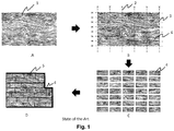
- FIG. 3A shows a ground floor (101) of e.g. a shop having an entrance (102), which has to become a personalized decorative surface.
- the shape and the dimensions of the ground floor (101) are taken and reproduced on a computer screen as a digital image of the personalized decorative surface (103) including a company logo of the shop as a floormarking "Logo” (104) which can be observed by a customer entering the shop, a floormarking "reception” (105) where an entering customer is welcomed and an area having a floormarking "Demo” (106) where a product is demonstrated to the customer.
- a staggered array (107) is applied to the digital image of the personalized decorative surface (103) segmenting it into a plurality of decorative laminate panel images (108) sized to fit on the decorative laminate panels.
- Each decorative laminate panel image (108) is assigned a positioning code (109) for identifying its position in the digital image of the personalized or customized decorative surface.
- the indicated decorative laminate panel image (108) in Figure 3B is assigned with " R2C4" as the positioning code.
- Figure 3C illustrates how the digital image of the personalized decorative surface (103) in Figure 3A has been segmented into individual decorative panel images (108).
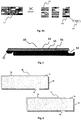
- the decorative panel images (108) of Figure 3C are collected and non-staggered digital layouts (110) of the plurality of decorative panel images are made that will fit on a substrate when inkjet printed.
- the non-staggered digital layouts (110) are inkjet printed together with the corresponding position code digital layouts (111) on a substrate (112), e.g. a paper web substrate.
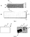
- the inkjet printed non-staggered digital layout (110) and the corresponding position code digital layout (111) will form a decorative layer (116) respectively a balancing layer (118) in a decorative laminate panel (119) as shown in Figure 2A .
- Figure 3G shows how a decorative laminate board (113) is heat pressed (114) from an assembly having, in order, a protective layer (115), a decorative layer (116), a core layer (117) and a balancing layer (118).
- the balancing layer (118) is present in the assembly so that the positioning codes are oriented away from the core layer (117), making them readable.
- the decorative laminate board (113) is divided into decorative laminate panels (119). For a specific decorative laminate panel (120), the panel back-side (120) is shown having "R5C1" as the corresponding positioning code (109) of the specific decorative laminate panel (120).
- the segmenting is preferably performed according to a staggered array. This may not be really necessary for decorative wall panels, but for flooring panels it is advantageous for obtaining a sturdy floor.
- the positioning code is applied on the back-side of a decorative laminate panel.
- it is preferably applied by inkjet printing or laser marking, more preferably it is applied simultaneously with the inkjet printing of the personalized or customized decorative surface as illustrated in Figure 3E .
- customer details or an identification code for identifying a customer or his delivery address are applied to the back-side of one or more, but most preferably all the decorative laminate panels.
- An advantage of having customer details or an identification code on each decorative laminate panel is that the reordering of a single decorative laminate panel is facilitated when a panel became damaged during transport or during assembly of the floor.
- the customer details or the identification code provide also advantages for track-and-trace in the manufacturing chain.
- the decorative laminate panels preferably have a tongue and groove for fast and easy assembly of e.g. a floor.
- the tongue and groove can be machined into the decorative laminate panels using so-called double end tetoners, as those available from HOMAG and KRAFT Maschinenbau.
- double end tetoners as those available from HOMAG and KRAFT Maschinenbau.
- a so-called extension zone is present having a width corresponding to that which is machined away for providing the tongue and groove.
- This extension zone may be left blank, but if the machining is performed inaccurately one or more white lines may be present in the decorative surface if the used substrate is white paper.
- the occurrence of white lines through inaccurate machining by double end tetoners is eliminated by repeating in the extension zone image data retrieved from neighbouring decorative laminate panel images in the digital image of the personalized or customized decorative surface.
- the substrate used for inkjet printing is preferably a paper substrate as the brings economical benefits.
- the inkjet printing of the non-staggered digital layout on the paper substrate is preferably performed by one or more aqueous pigmented inkjet inks.
- the latter can be before or after thermosetting resin impregnation, but is preferably performed before thermosetting resin impregnation.
- aqueous pigmented inkjet inks provides advantages for image permanence (light fading minimized by pigments) and for safety and environmental advantages as aqueous inks are used instead of organic solvent based inks.
- the one or more aqueous pigmented inkjet inks are preferably inkjet printed on one or more ink-receiving layers present on the paper substrate.
- the at least one ink-receiving layer contains a polyvinylalcohol polymer and an inorganic pigment.
- an outermost ink-receiving layer contains no inorganic pigment or contains a smaller content of inorganic pigment than an ink-receiving layer between the paper substrate and the outermost ink-receiving layer.
- the positioning code is inkjet printed on a paper substrate for forming a balancing layer in the decorative laminate panel.
- This inkjet printing is preferably performed together with the inkjet printing of the non-staggered digital layout as shown in Figure 3E , i.e. one after the other. This way errors of combining the decorative layer and the balancing layer in the assembly shown in Figure 3F are minimized.
- the paper substrate is preferably replaced by a thermoplastic substrate based on a material selected from the group consisting of polyvinylchloride (PVC), polypropylene (PP), polyethylene (PE), polyethylene-terephthalate (PET) and thermoplastic polyurethane (TPU) and combinations thereof.
- PVC polyvinylchloride
- PP polypropylene
- PE polyethylene
- PET polyethylene-terephthalate
- TPU thermoplastic polyurethane
- the decorative laminate panel image or the positioning code is inkjet printed using one or more free radical UV curable inkjet inks instead of solvent based inkjet inks as this brings not only economical and environmental advantages, but also for image quality as UV curing can freeze the jetted image.
- the decorative laminate usually a decorative board, is divided into decorative laminate panels by following vertical and horizontal cutting lines as shown in Figure 3G .
- the latter is possible by inkjet printing a non-staggered digital layout (110) as shown in Figure 3D .
- the personalized or customized decorative image may include wood grain as a background. It was found that the classic CMYK inkjet ink set was insufficiently capable of reproducing all the different shades in wood colour. One could resolve this by including an additional brown or red inkjet ink, however this makes the inkjet printing more costly and more complex (e.g. colour management). It was found that by replacing the magenta inkjet ink by a red inkjet ink, that a high colour gamut could be retained while simultaneously being capable to print all desired brown colours present in wood grain images. This was especially true if the red inkjet ink contained a red pigment selected from the group consisting of C.I. Pigment Red 254, CI. Pigment Red 176 and C.I. Pigment Red 122 or mixed crystals thereof.
- a red pigment selected from the group consisting of C.I. Pigment Red 254, CI. Pigment Red 176 and C.I. Pigment Red 122 or mixed crystals thereof.
- a CRYK inkjet ink set was generally also capable of reproducing most customized and personalized images.
- a higher image quality colour vibrancy
- the inkjet ink set may also be extended by the combination of full density inkjet inks with light density inkjet inks. The combination of such dark and light colour inks and/or black and grey inks improves the image quality by a lowered graininess.
- a particularly preferred CRYK inkjet ink set contains a black inkjet ink containing a carbon black pigment, a yellow inkjet ink containing a yellow pigment selected from the group consisting of C.I. Pigment Yellow 150, C.I. Pigment Yellow 151 and mixed crystals thereof; a red inkjet ink contained a red pigment selected from the group consisting of C.I. Pigment Red 254, CI. Pigment Red 176, C.I. Pigment Red 122 and mixed crystals thereof; and a cyan inkjet ink containing a beta-copper phthalocyanine pigment.
- C.I. Pigment Yellow 150 in the yellow inkjet ink and a beta-copper phthalocyanine pigment, such as C.I. Pigment Blue 15:3 or C.I. Pigment Blue 15:4, provided laminate panels exhibiting excellent light stability.
- a CRYK inkjet ink set is used containing a black inkjet ink containing a carbon black pigment, a yellow inkjet ink containing a yellow pigment selected from the group consisting of C.I. Pigment Yellow 150 or mixed crystals thereof; a red inkjet ink contained a red pigment selected from the group consisting of C.I. Pigment Red 254, CI. Pigment Red 176 or mixed crystals thereof; and a cyan inkjet ink containing a beta-copper phthalocyanine pigment.
- some of the decorative laminate panels i.e. at least the decorative laminate panels containing image details other than a background of e.g. a wood-grain, but preferably all decorative laminate panels, are provided with a positioning code.
- a positioning code on all decorative laminate panels ensures that, for example, a cartoon character printed on decorative panels for a children's bedroom will not be hidden by a bed or cupboard.
- the positioning codes may be applied in any desired form.
- the numbers can be printed, laser marked or labelled on the back- side of a decorative laminate panel.
- the positioning code may consist of plain numbers (1, 2, 3, 4, 5,...) or they can have a form RnCm with R representing a row , C representing a column and n and m representing integers.
- R representing a row
- C representing a column
- n and m representing integers.
- a first decorative laminate panel may have the number R1C1
- the decorative laminate panel on the right side will have the number R1C2.
- the first decorative laminate panel in a second row above the first decorative laminate panel will have the number R2C1.
- An illustration of this positioning code is shown in Figure 3B .
- the positioning code helps the customer to assemble the decorative laminate panels into the correct staggered arrangement reproducing the personalized or customized decorative surface.
- an assembly layout is included in the packaging of a set of decorative laminate panels.
- a code may be applied on the packaging, such as a barcode or a QR code, which can be scanned by e.g. a smart phone to visualize or print the assembly layout.
- the manufacturing of decorative laminates resulted in a mass product allowing only limited customization and no personalization.
- the current inkjet printing method allows that the decorative patterns are customized and even personalized by the customer.
- Personalization can, for example, be the inkjet printing of a kid's favourite cartoon character on floor laminates for his bedroom.
- Customization means that a limited series of decorative surfaces are made, for example, similar sets of floor laminate panels for a chain of shops.
- an identification code is preferably generated upon ordering by a customer of a set of decorative laminate panels for directly or indirectly linking the set of decorative laminate panels to the customer of his delivery address.
- the identification code is preferably printed on the back-side of decorative laminate panel.
- both an identification code and customer details are applied, preferably inkjet printed, on the back-side of decorative laminate panel.
- the identification code is preferably used for identifying a set of decorative laminate panels and its customer. In the latter case, the identification code is directly or indirectly connected to the customer or his delivery address.
- the wording "directly connected” means that no intermediate codes or linkages are used, but that the identification code corresponds in a database directly to the customer.
- "Indirectly connected” means that a series of codes is used that taken together makes a connection between the printed identification code and the customer.
- the series of codes may include a print code given by the decor printer and a manufacturing code given by the laminate manufacturer. By using this series of codes in perhaps several databases, the customer and his delivery address can be retrieved.
- the identification code is directly connected to the customer or his delivery address. By a direct connection, less errors occur thereby avoiding delivery at the wrong customer or even loss of the actual customer information.
- the identification code can be applied by any suitable manner, such as inkjet printing, laser marking or using an adhesive label applicator.
- the identification code is applied by inkjet printing, preferably by the one or more inkjet inks for printing the decorative pattern.
- inkjet printing is simplified as no extra measures or equipment is necessary.
- laser marking is used, a synchronisation between the inkjet printing device printing the decorative pattern and the laser marking equipment applying the identification code is required.
- This is also necessary for the adhesive label application, where furthermore some labels may get detached during the process (e.g. during the impregnation process of a printed paper substrate web) thereby destroying the connection with the customer.
- the identification code may be a simple bar code, which can be simply scanned by a handheld barcode scanner during the manufacturing process. It may also be a so-called 2D code.
- Preferred 2D codes include a QR code, a datamatrix code, a cool-data-matrix code, an aztec code, an upcode, a trillcode, a quickmark code, a shot code, a mcode, a beetagg and the like.
- the identification code may be changed during the ordering and the manufacturing process and thus need not be identical to the one created when, as shown by Fig.7 and Fig.8 , a customer (201) defines a laminate order (202) via an input device (203) digitally connected (204) to a computer (205).
- the identification code may be updated for track-and-trace purposes throughout the manufacturing chain, so that it can be determined at which stage of the manufacturing process or delivery process the laminate order has arrived.
- the connection with the customer should be maintained, for example, in a database of the computer (205).
- the database may contain a series of codes connected to the laminate order.
- the type of codes used at a decor printer (213) may differ from those used at the laminate manufacturer (220) as different types of scanners or different software are used.
- An identification code on a substrate web can be used for a wide range of purposes. A non-exclusive list of purposes is given here below.
- an identification code can be used for identifying a set of decorative laminate panels to be manufactured for a customer. This occurs in Fig.7 and Fig.8 when a customer (201) defines a laminate order (202) on an input device (203) digitally connected (204) to a computer (205).
- the definition of the laminate order includes not only the brand, the decoration pattern and the number of panels needed, but may involve items related to the finishing such as V-groove or not, quality level (AC3-AC4-AC5), thickness of the panel, uploaded personalized image files (e.g. company logo, cartoon character for a child's bedroom floor, etc.
- the identification code can be used for identifying a decorative substrate web manufacturer (decor printer) as different brands (laminate manufacturers) may work with different decor printers.
- the identification code can be used for identifying a decorative image to be inkjet printed by the decor printer ( Fig.7 ) or the decorative laminate manufacturer ( Fig.8 ).
- the identification of the decorative image may include the uploading of personalized image files.
- the identification code can be used for identifying a decorative laminate manufacturer, as he may use a different width of paper rolls for impregnation. It may also be simply for logistic reasons, such as delivering the printed decor substrate web to the decorative laminate manufacturer after it has been completed.
- the identification code can be used for aggregating the print jobs of the laminate orders by the decorative substrate web manufacturer into an aggregate print job to be printed on one and the same substrate web for the decorative laminate manufacturer.
- the identification code can be used for enabling the decorative laminate manufacturer to track the progress of delivery of the inkjet printed substrate web by the decorative substrate web manufacturer. This way the laminate manufacturer can plan his production in an efficient and economical manner.
- the identification code can be used for identifying the customer of the set of decorative laminate panels so that it can be shipped to the customer. At the same time, it can be checked if the laminate order is complete.
- One package of decorative panels usually contains enough panels to cover a surface of about one square meter. If the customer ordered 24.5 m 2 of decorative panels, then it can be checked if there are 25 packages.
- the identification code can be used not only to retrieve the delivery address, but also for automatically printing shipping labels for delivering the set of decorative laminate panels to the customer.
- the identification code can be used for delivering the set of decorative laminate panels to the customer.
- a machine readable identification code can be scanned during the transport process for enabling the customer to track the progress of delivery of the set of decorative laminate panels. If the customer is a laminate shop, then the shop can use the identification code for informing the end-customer if the decorative panels have already been manufactured or are in transport.
- the identification code can be used for authentication of the set of decorative laminate panels. This is especially useful if a customer would order decorative panels of a certain brand via the internet and wants to confirm via the brand website if the received decorative panels are not made by an alternative laminate manufacturer delivering decorative panels of inferior quality.
- the identification code may also serve for marketing purposes, such as customer engagement.
- Customer engagement is a business communication connection between an external stakeholder (customer) and an organization (company or brand).
- the connection can take place online or offline.
- the connection is made online, for example when the customer scans the identification code with his smartphone and is taken to a certain website of the laminate manufacturer or brand to enhance the overall customer experience.
- the identification code may be used during manufacturing for retrieving information for manufacturing operations, i.e. for automation of manufacturing. For example, information on the size of sheets to be cut from the substrate web can be retrieved. Laminate boards may be cut to a length of e.g. 1.24 m or 2.48 m. By connecting this information to the information code, the cutting process of the substrate web can be automated.
- the present invention also provides a decorative laminate panel as obtained by a manufacturing method disclosed here above.
- a decorative laminate panel for a personalized or customized decorative surface according to a preferred embodiment of the present invention, wherein: the front side of the decorative laminate panel includes an inkjet printed decorative laminate panel image that represents a portion of the personalized or customized decorative surface; and the back side of decorative laminate panel includes a positioning code for positioning the decorative laminate panel in the correct location of the personalized or customized decorative surface.
- the back-side of the decorative laminate panel further includes customer details or an identification code for identifying a customer or his delivery address. This allows timely delivery of the finished decorative laminate panels, especially in the case where both a decor printer and a laminate manufacturer are involved.
- Decorative laminate panels are usually shipped in a package including a set of decorative laminate panels covering about 1 m 2 of surface. This allows easy handling when assembling the decorative surface.
- a set of decorative laminate panels includes at least one decorative laminate panel according to the present invention described here above. It is not imperative that all decorative laminate panels have a positioning code on the back-side of the panel.
- a set may contain a single decorative laminate panel including part of a personalized image, e.g. a cartoon figure for the floor of a child's bedroom, while the other panels are merely "background" panels, such as wood-grain panels shown in Figure 1 .
- a correct positioning is not necessary as it does not provide a disturbing distorted decorative image, thus allowing random selection of such a background panel.
- each decorative laminate panel includes a positioning code on the back-side of decorative laminate panel. The latter is especially useful for very large surfaces.
- the set of decorative laminate panels includes an assembly layout in the package.
- the assembly layout helps to position the decorative laminate panels in the correct position so that the original personalized or customized decorative surface image is reproduced on e.g. a floor if the decorative laminate panels are floor panels.
- the assembly layout may be a physical assembly layout or a virtual assembly layout.
- An example of a physical assembly layout is an assembly layout printed on a piece of paper accompanying the decorative laminate panels in a package or more preferably an assembly layout printed on the back-side of a decorative laminate panel.
- a virtual assembly layout is most preferably printed as a code on the back-side of a decorative laminate panel.
- the virtual assembly layout can be a QR-code or a barcode, which can be scanned by a smart phone to download the assembly layout to the smartphone.
- the identification code can be used to download the assembly layout from a website.
- FIG. 3B An illustration of an assembly layout is given in Figure 3B as the staggered array containing the "RnCm" position codes with n and m representing integers.
- the decorative laminate panels come in two forms.
- the decorative panels for multi-purpose applications include a paper substrate preferably having one or more ink-receiving layers whereon aqueous pigmented inkjet inks have been printed before impregnation by a thermosetting resin.
- a thermosetting resin such panels will be referred to here below as "wood-based laminate panels”.
- the decorative laminate panels include a thermoplastic substrate printed upon by one or more UV curable inkjet inks. Such panels will be referred to here below as “thermoplastic laminate panels”.
- a base layer and a core layer have the same purpose of providing some strength to the decorative laminate panel, so that it does not break into pieces when bent.
- the base layer (55) in a thermoplastic decorative laminate panel corresponds to the core layer (41) in a wood based decorative laminate panel.
- Another aspect of the invention is to provide a set of decorative laminate panels obtained by a manufacturing method as described above, wherein the decorative laminate panels assembled in staggered arrangement are capable of reproducing the requested personalized of customized decorative image without any distortion.
- the decorative laminate panels in the set of decorative laminate panels preferably have a tongue and groove connection, more preferably further including an alignment aid for achieving the selected staggering distance between two decorative laminate panels.
- FIG. 7 An example of an alignment aid (74+75) is shown in Figure 7 .
- the missing part of a tongue (74) and the unmilled groove (75) can be slid into each other because they have similar dimensions and shape, preferably the same dimensions and shape.
- a wood-based laminate panel contains at least a core layer, a decorative layer and a protective layer and preferably contains also a balancing layer.
- a cross-section of such a decorative panel is shown by Fig.2 .
- a decorative panel like a floor panel, has a decorative layer on one side of the core layer and a balancing layer on the other side of the core layer.
- the decorative panels are preferably selected from the group consisting of flooring panels, ceiling panels and wall panels, more preferably the decorative panels are flooring panels.
- a protective layer is applied on top of the decorative layer.
- a balancing layer may be applied on the opposite side of the core layer to restrict or prevent possible bending of the decorative panel.
- the assembly into a decorative panel of the balancing layer, the core layer, the decorative layer, and a protective layer is preferably performed in the same press treatment of preferably a DPL process (Direct Pressure Laminate).
- tongue and groove profiles (122 respectively 123 in Fig.2 ) are milled into the side of individual decorative panels which allow them to slide into one another, preferably after applying glue to them.
- the tongue and grove join ensures, in the case of flooring panels, a sturdy floor construction and protects the floor, preventing dampness or water from penetrating.
- the decorative panels include a tongue and a groove of a special shape (e.g. 51 respectively 52 in Fig.4 ) which allow them to be clicked into one another.
- a special shape e.g. 51 respectively 52 in Fig.4
- the advantage thereof is an easy assembly requiring no glue.
- the shape of the tongue and groove necessary for obtaining a good mechanical join is well-known in the art of laminate flooring, as also exemplified in EP 2280130 A (FLOORING IND), WO 2004/053258 (FLOORING IND), US 2008010937 (VALINGE) and US 6418683 (PERSTORP FLOORING).
- the decorative panels may further include a sound-absorbing layer as disclosed by US 8196366 (UNILIN).
- the decorative panel is an antistatic layered panel.
- Techniques to render decorative panels antistatic are well-known in the art of decorative laminates as exemplified by EP 1567334 A (FLOORING IND).
- the top surface of the decorative laminate panel i.e. at least the protective layer, is preferably provided with a relief matching the background image, such as for example the wood grain, cracks and knots in a woodprint.
- Embossing techniques to accomplish such relief are well-known and disclosed by, for example, EP 1290290 A (FLOORING IND), US 2006144004 (UNILIN), EP 1711353 A (FLOORING IND) and US 2010192793 (FLOORING IND).
- the relief is formed by pressing a digital embossing plate against the top layer of the decorative workpiece or nested decorative workpiece.
- a digital embossing plate can be made by UV curable inkjet technology so that the relief corresponds to the background image printed on the substrate web.
- An advantage of inkjet over gravure printing is that the background image, e.g. a wood grain image, can be varied infinitely so that no repeating decorative laminate panels occur in a room.
- a digital embossing plate a variation in the inkjet printed decorative image can be constantly matched by a variation in the relief.
- a digital embossing plate is a plate, which comprises elevations that can be used to form a relief on decorative laminate panel by pressing the digital embossing plate against the protective layer.
- the elevations may be cured inkjet droplets, jetted by an inkjet print device, and most preferably UV cured inkjet droplets.
- the elevations are preferably formed by printing and curing inkjet droplets on top of already cured or pin-cured inkjet droplets.
- the plate is preferably stiff by using metal or hard plastic.
- An alternative of a digital embossing plate may be a digital embossing cylinder which is a cylinder that comprises the elevations to form a relief on decorative laminate by pressing and rotating the digital embossing cylinder against the top layer of the decorative laminate board.
- the elevations on the digital embossing cylinder are preferably cured inkjet droplets, jetted by an inkjet print device, and most preferably UV cured inkjet droplets.
- the elevations are preferably formed by printing and curing inkjet droplets on top of already cured or pin-cured inkjet droplets.
- the decorative panels are made in the form of rectangular oblong strips.
- the dimensions thereof may vary greatly.
- the panels have a length exceeding 1 meter, and a width exceeding 0.1 meter, e.g. the panels can be about 1.3 meter long and about 0.15 meter wide.
- the length of the panels exceeds 2 meter, with the width being preferably about 0.2 meter or more.
- the print of such panels is preferably free from repetitions.
- the decorative layer includes a thermosetting resin impregnated paper and a personalized or customized decorative image printed thereon by inkjet. It is preferably prepared by an inkjet printing on a paper substrate web, followed by impregnation with a thermosetting resin.
- the core layer is preferably made of wood-based materials, such as particle board, MDF or HDF (Medium Density Fibreboard or High Density Fibreboard), Oriented Strand Board (OSB) or the like. Also, use can be made of boards of synthetic material or boards hardened by means of water, such as cement boards. In a particularly preferred embodiment, the core layer is a MDF or HDF board.
- MDF or HDF Medium Density Fibreboard or High Density Fibreboard
- OSB Oriented Strand Board
- the core layer is a MDF or HDF board.
- the core layer may also be assembled at least from a plurality of paper sheets, or other carrier sheets, impregnated with a thermosetting resin as disclosed by WO 2013/050910 (UNILIN).
- Preferred paper sheets include so-called Kraft paper obtained by a chemical pulping process also known as the Kraft process, e.g. as described in US 4952277 (BET PAPERCHEM) .
- the core layer is a board material composed substantially of wood fibres which are bonded by means of a polycondensation glue, wherein the polycondensation glue forms 5 to 20 percent by weight of the board material and the wood fibres are obtained for at least 40 percent by weight from recycled wood.
- a polycondensation glue forms 5 to 20 percent by weight of the board material and the wood fibres are obtained for at least 40 percent by weight from recycled wood.
- the thickness of the core layer is preferably between 2 and 12 mm, more preferably between 5 and 10 mm.
- the decorative layer and preferably also the protective layer include paper as substrate.
- the balancing layer preferably includes paper as substrate.
- the paper preferably has a weight of less than 150 g/m 2 , because heavier paper sheets are hard to impregnate all through their thickness with a thermosetting resin.
- Preferably said paper layer has a paper weight, i.e. without taking into account the resin provided on it, of between 50 and 130 g/m 2 and preferably between 70 and 130 g/m 2 .
- the weight of the paper cannot be too high, as then the amount of resin needed to sufficiently impregnate the paper would be too high, and reliably further processing the printed paper in a pressing operation becomes badly feasible.
- the paper sheets have a porosity according to Gurley's method (DIN 53120) of between 8 and 25 seconds.
- Gurley's method DIN 53120
- Such porosity allows even for a heavy sheet of more than 150 g/m 2 to be readily impregnated with a relatively high amount of resin.
- Suitable paper sheets having high porosity and their manufacturing are also disclosed by US 6709764 (ARJO WIGGINS).
- the paper for the decorative layer is preferably a white paper and may include one or more whitening agents, such as titanium dioxide, calcium carbonate and the like.
- whitening agents such as titanium dioxide, calcium carbonate and the like.
- the presence of a whitening agent helps to mask differences in colour on the core layer that can cause undesired colour effects on the decorative image.
- the paper for the decorative layer may be a bulk coloured paper including one or more colour dyes and/or colour pigments.
- a coloured paper reduces the amount of inkjet ink required to print the decorative image.
- a light brown or grey paper may be used for printing a wood motif as background image in order to reduce the amount of inkjet ink needed.
- unbleached Kraft paper is used for a brownish coloured paper in the decorative layer.
- Kraft paper has a low lignin content resulting in a high tensile strength.
- a preferred type of Kraft paper is absorbent Kraft paper of 40 to 135 g/m 2 having a high porosity and made from clean low kappa hardwood Kraft of good uniformity.
- the protective layer includes a paper
- a paper is used which becomes transparent or translucent after resin impregnation and heat pressing so that the decorative image of the decorative layer can be viewed.
- thermosetting resin is preferably selected from the group consisting of melamine-formaldehyde based resins, ureum-formaldehyde based resins and phenol-formaldehyde based resins.
- Other suitable resins for impregnating the paper are listed in [0028] of EP 2274485 A (HUELSTA).
- thermosetting resin is a melamine-formaldehyde based resin, often simply referred to in the art as a 'melamine (based) resin'.
- the melamine formaldehyde resin preferably has a formaldehyde to melamine ratio of 1.4 to 2.
- Such melamine based resin is a resin that polycondensates while exposed to heat in a pressing operation.
- the polycondensation reaction creates water as a by-product.
- the created water, as well as any water residue in the thermosetting resin before the pressing, must leave the hardening resin layer to a large extent before being trapped and leading to a loss of transparency in the hardened layer.
- the available ink layer can hinder the diffusion of the vapour bubbles to the surface, however the present invention provides measures for limiting such hindrance.
- the paper is preferably provided with an amount of thermosetting resin equalling 40 to 250% dry weight of resin as compared to weight of the paper.
- this range of applied resin provides for a sufficient impregnation of the paper, that avoids splitting to a large extent, and that stabilizes the dimension of the paper to a high degree.
- the paper is preferably provided with such an amount of thermosetting resin, that at least the paper core is satisfied with the resin. Such satisfaction can be reached when an amount of resin is provided that corresponds to at least 1.5 or at least 2 times the paper weight.
- the paper is firstly impregnated through or satisfied, and, afterwards, at least at the side thereof to be printed, resin is partially removed.
- the resin provided on said paper is in a B-stage while printing.
- Such B-stage exists when the thermosetting resin is not completely cross linked.
- the resin provided on said paper has a relative humidity lower than 15%, and still better of 10% by weight or lower while printing.
- the step of providing said paper with thermosetting resin involves applying a mixture of water and the resin on the paper.
- the application of the mixture might involve immersion of the paper in a bath of the mixture.
- the resin is provided in a dosed manner, for example by using one or more squeezing rollers and/or doctor blades to set the amount of resin added to the paper layer.
- VITS Methods for impregnating a paper substrate with resin are well-known in the art as exemplified by WO 2012/126816 (VITS) and EP 966641 A (VITS).
- the dry resin content of the mixture of water and resin for impregnation depends on the type of resin.
- An aqueous solution containing a phenol-formaldehyde resin preferably has a dry resin content of about 30% by weight, while an aqueous solution containing a melamine-formaldehyde resin preferably has a dry resin content of about 60% by weight.
- Methods of impregnation with such solutions are disclosed by e.g. US 6773799 (DECORATIVE SURFACES).
- the paper is preferably impregnated with the mixtures known from US 4109043 (FORMICA CORP) and US 4112169 (FORMICA CORP), and hence preferably comprise, next to melamine formaldehyde resin, also polyurethane resin and/or acrylic resin.
- the mixture including the thermosetting resin may further include additives, such as colorants, surface active ingredients, biocides, antistatic agents, hard particles for wear resistance, elastomers, UV absorbers, organic solvents, acids, bases, and the like.
- additives such as colorants, surface active ingredients, biocides, antistatic agents, hard particles for wear resistance, elastomers, UV absorbers, organic solvents, acids, bases, and the like.
- the advantage of adding a colorant to the mixture containing the thermosetting resin is that a single type of white paper can be used for manufacturing the decorative layer, thereby reducing the stock of paper for the decorative laminate manufacturer.
- the use of a colored paper, as already described above, to reduce the amount of ink required for printing a decorative image, is here accomplished by a white paper being colored by impregnation using a brownish thermosetting resin. The latter allows a better control of the amount of brown colour required for certain wood motifs.
- Antistatic agents may be used in thermosetting resin. However preferably antistatic agents, like NaCl and KCI, carbon particles and metal particles, are absent in the resin, because often they have undesired side effects such as a lower water resistance or a lower transparency. Other suitable antistatic agents are disclosed by EP 1567334 A (FLOORING IND).
- aqueous pigmented inkjet inks are preferably inkjet printed on one or more ink-receiving layers present on a paper substrate. It is also possible to omit the one or more ink-receiving layers by using a polymer latex binder in the aqueous pigmented inkjet inks. However, most preferably one or more ink-receiving layers are used for maximizing the image quality.
- An inkjet printed paper substrate web is thereafter impregnated by a thermosetting resin.
- the ink-receiving layer may consist of a single layer or of two, three or more layers, wherein each may have a different composition.
- a single ink-receiving layer may be used, but preferably at least two ink-receiving layers.
- An ink-receiving layer preferably includes a polymeric binder and, for fast drying of the inkjet printed ink, preferably also an inorganic pigment.
- a particularly preferred ink-receiving layer contains a polyvinylalcohol and an inorganic pigment, preferably a silica-based pigment.
- one or more of the ink-receiving layers contain an inorganic pigment and a polymeric binder having a weight ratio P/B of inorganic pigment P to polymeric binder B of larger than 1.5, preferably larger than 3.0.
- the inorganic pigment may be a single type of inorganic pigment or a plurality of different inorganic pigments.
- the polymeric binder may be a single type of polymeric binder or a plurality of different polymeric binders.
- At least two inkjet receiving layers are present on the paper substrate, wherein an outermost ink-receiving layer has no or a smaller content of inorganic pigment than an ink-receiving layer between the paper substrate web and the outermost ink-receiving layer.
- the one or more ink-receiving layers have a total dry weight between 2.0 g/m 2 and 10.0 g/m 2 , more preferably between 3.0 and 6.0 g/m 2 .
- the ink-receiving layer includes a polymeric binder selected from the group consisting of hydroxyethyl cellulose; hydroxypropyl cellulose; hydroxyethylmethyl cellulose; hydroxypropyl methyl cellulose; hydroxybutylmethyl cellulose; methyl cellulose; sodium carboxymethyl cellulose; sodium carboxymethylhydroxethyl cellulose; water soluble ethylhydroxyethyl cellulose; cellulose sulfate; polyvinyl alcohol; vinylalcohol copolymers; polyvinyl acetate; polyvinyl acetal; polyvinyl pyrrolidone; polyacrylamide; acrylamide/acrylic acid copolymer; polystyrene, styrene copolymers; acrylic or methacrylic polymers; styrene/acrylic copolymers; ethylene-vinylacetate copolymer; vinyl-methyl ether/maleic acid copolymer; poly(2-acryla) binder selected from
- the ink-receiving layer includes a polymeric binder, preferably a water soluble polymeric binder (> 1 g/L water), which has a hydroxyl group as a hydrophilic structural unit, e.g. a polyvinyl alcohol.
- a polymeric binder preferably a water soluble polymeric binder (> 1 g/L water), which has a hydroxyl group as a hydrophilic structural unit, e.g. a polyvinyl alcohol.
- a preferred polymer for the ink-receiving layer is a polyvinylalcohol (PVA), a vinylalcohol copolymer or a modified polyvinyl alcohol.
- the modified polyvinyl alcohol may be a cationic type polyvinyl alcohol, such as the cationic polyvinyl alcohol grades from Kuraray, such as POVAL C506, POVAL C118 from Nippon Goshei.
- the pigment in the ink-receiving layer is an inorganic pigment, which can be chosen from neutral, anionic and cationic pigment types.
- Useful pigments include e.g. silica, talc, clay, hydrotalcite, kaolin, diatomaceous earth, calcium carbonate, magnesium carbonate, basic magnesium carbonate, aluminosilicate, aluminum trihydroxide, aluminum oxide (alumina), titanium oxide, zinc oxide, barium sulfate, calcium sulfate, zinc sulfide, satin white, alumina hydrate such as boehmite, zirconium oxide or mixed oxides.
- the inorganic pigment is preferably selected from the group consisting of alumina hydrates, aluminum oxides, aluminum hydroxides, aluminum silicates, and silicas.
- Particularly preferred inorganic pigments are silica particles, colloidal silica, alumina particles and pseudo-boehmite, as they form better porous structures.
- the particles may be primary particles directly used as they are, or they may form secondary particles.
- the particles Preferably, the particles have an average primary particle diameter of 2 ⁇ m or less, and more preferably 200 nm or less.
- a preferred type of alumina hydrate is crystalline boehmite, or ⁇ -AlO(OH).
- Useful types of boehmite include DISPERAL HP14, DISPERAL 40, DISPAL 23N4-20, DISPAL 14N-25 and DISPERAL AL25 from Sasol; and MARTOXIN VPP2000-2 and GL-3 from Martinswerk GmbH
- Useful cationic aluminum oxide (alumina) types include ⁇ -Al 2 O 3 types, such as NORTON E700, available from Saint-Gobain Ceramics & Plastics, Inc, and ⁇ -Al 2 O 3 types, such as ALUMINUM OXID C from Degussa.
- ⁇ -Al(OH) 3 such as PLURAL BT, available from Sasol, and Gibbsite, or ⁇ -Al(OH) 3 , such as MARTINAL grades and MARTIFIN grades from Martinswerk GmbH , MICRAL grades from JM Huber company; HIGILITE grades from Showa Denka K.K..
- silica which can be used as such, in its anionic form or after cationic modification.
- the silica can be chosen from different types, such as crystalline silica, amorphous silica, precipitated silica, fumed silica, silica gel, spherical and non-spherical silica.
- the silica may contain minor amounts of metal oxides from the group Al, Zr, Ti.
- Useful types include AEROSIL OX50 (BET surface area 50 ⁇ 15 m 2 /g, average primary particle size 40 nm, SiO 2 content > 99.8%, Al 2 O 3 content ⁇ 0.08%), AEROSIL MOX170 (BET surface area 170 g/m 2 , average primary particle size 15 nm, SiO 2 content > 98.3%, Al 2 O 3 content 0.3-1.3%), AEROSIL MOX80 (BET surface area 80 ⁇ 20 g/m 2 , average primary particle size 30 nm, SiO 2 content > 98.3%, Al 2 O 3 content 0.3-1.3%), or other hydrophilic AEROSIL grades available from Degussa-Huls AG, which may give aqueous dispersions with a small average particle size ( ⁇ 500 nm).
- AEROSIL OX50 BET surface area 50 ⁇ 15 m 2 /g, average primary particle size 40 nm, SiO 2 content > 99.8%, Al 2 O 3
- silica particles are grouped into two types, wet-process particles and dry-process (vapour phase-process or fumed) particles.
- active silica is formed through acidolysis of silicates, and this is polymerized to a suitable degree and flocculated to obtain hydrous silica.
- a vapour-phase process includes two types; one includes high-temperature vapour-phase hydrolysis of silicon halide to obtain anhydrous silica (flame hydrolysis), and the other includes thermal reduction vaporization of silica sand and coke in an electric furnace followed by oxidizing it in air to also obtain anhydrous silica (arc process).
- the "fumed silica” means to indicate anhydrous silica particles obtained in the vapour-phase process.
- the fumed silica particles used in the invention especially preferred are the fumed silica particles.
- the fumed silica differs from hydrous silica in point of the density of the surface silanol group and of the presence or absence of pores therein, and the two different types of silica have different properties.
- the fumed silica is suitable for forming a three-dimensional structure of high porosity. Since the fumed silica has a particularly large specific surface area, its ink absorption and retention are high.
- the vapour-phase silica has an average primary particle diameter of 30 nm or less, more preferably 20 nm or less, even more preferably 10 nm or less, and most preferably from 3 to 10 nm.
- the fumed silica particles readily aggregate through hydrogen bonding at the silanol groups therein. Therefore, when their mean primary particle size is not larger than 30 nm, the silica particles may form a structure of high porosity.
- an ink-receiving layer may be crosslinked. Any suitable crosslinker known in the prior art can be used. Boric acid is particularly preferred as crosslinker for the one or more ink-receiving layers used in the present invention.
- the ink-receiving layer(s) may include other additives, such as colorants, surfactants, biocides, antistatic agents, hard particles for wear resistance, elastomers, UV absorbers, organic solvents, plasticizers, light-stabilizers, pH adjusters, antistatic agents, whitening agents, matting agents and the like.
- additives such as colorants, surfactants, biocides, antistatic agents, hard particles for wear resistance, elastomers, UV absorbers, organic solvents, plasticizers, light-stabilizers, pH adjusters, antistatic agents, whitening agents, matting agents and the like.
- the ink-receiving layer(s) can be coated onto the paper substrate by any conventional coating technique, such as dip coating, knife coating, extrusion coating, spin coating, slide hopper coating and curtain coating.
- the ink-receiving layer(s) can also be applied by a printing techniques, such as flexographic printing or valvejet printing.
- a protective layer is applied above the decorative image by way of an overlay, i.e. a resin provided carrier, or a liquid coating, preferably while the decorative layer is laying on the core layer, either loosely or already connected or adhered thereto.
- an overlay i.e. a resin provided carrier, or a liquid coating
- the carrier of the overlay is a paper impregnated by a thermosetting resin that becomes transparent or translucent after heat pressing in a DPL process.
- the liquid coating includes preferably a thermosetting resin, but may also be another type of liquid such as a UV- or an EB-curable varnish.
- the liquid coating includes a melamine resin and hard particles, like corundum.
- the protective layer is preferably the outermost layer, but in another embodiment a thermoplastic or elastomeric surface layer may be coated on the protective layer, preferably of pure thermoplastic or elastomeric material. In the latter case, preferably a thermoplastic or elastomeric material based layer is also applied on the other side of the core layer.
- Liquid melamine coatings are exemplified in DE 19725829 C (LS INDUSTRIELACKE) and US 3173804 (RENKL PAIDIWERK).
- the liquid coating may contain hard particles, preferably transparent hard particles.
- Suitable liquid coatings for wear protection containing hard particles and methods for manufacturing such a protective layer are disclosed by US 2011300372 (CT FOR ABRASIVES AND REFRACTORIES) and US 8410209 (CT FOR ABRASIVES AND REFRACTORIES).
- the transparency and also the colour of the protective layer can be controlled by the hard particles, when they comprise one or a plurality of oxides, oxide nitrides or mixed oxides from the group of elements Li, Na, K, Ca, Mg, Ba, Sr, Zn, Al, Si, Ti, Nb, La, Y, Ce or B.
- the total quantity of hard particles and transparent solid material particles is typically between 5% by volume and 70% by volume, based on the total volume of the liquid coating.
- the total quantity of hard particles is between 1 g/m 2 and 100 g/m 2 , preferably 2 g/m 2 to 50 g/m 2 .
- the hard particles such as aluminium oxide particles
- the hard particles are preferably incorporated in or on the paper.
- Preferred hard particles are ceramic or mineral particles chosen from the group of aluminium oxide, silicon carbide, silicon oxide, silicon nitride, tungsten carbide, boron carbide, and titanium dioxide, or from any other metal oxide, metal carbide, metal nitride or metal carbonitride.
- the most preferred hard particles are corundum and so-called Sialon ceramics. In principle, a variety of particles may be used. Of course, also any mixture of the above-mentioned hard particles may be applied.
- the amount of hard particles in the protective layer may be determined in function of the desired wear resistance, preferably by a so-called Taber test as defined in EN 13329 and also disclosed in WO 2013/050910 A (UNILIN) and US 8410209 (CT FOR ABRASIVES AND REFRACTOR).
- Hard particles having an average particle size of between 1 and 200 ⁇ m are preferred.
- an amount of such particles of between 1 and 40 g/m 2 is applied above the printed image.
- An amount lower than 20 g/m 2 can suffice for the lower qualities.
- the protective layer includes a paper, then it preferably has a paper weight of between 10 and 50 g/m 2 .
- a paper is often also referred to as a so-called overlay commonly used in laminate panels. Preferred methods for manufacturing such an overlay are disclosed by WO 2007/144718 (FLOORING IND).
- the step of providing the protective layer of thermosetting resin above the printed image involves a press treatment.
- a temperature above 150°C is applied in the press treatment, more preferably between 180° and 220°C, and a pressure of more than 20 bar, more preferably between 35 and 40 bar.
- the main purpose of the balancing layer(s) is to compensate tensile forces by layers on the opposite side of the core layer, so that an essentially flat decorative panel is obtained.
- a balancing layer is preferably a thermosetting resin layer that can comprise one or more carrier layers, such as paper sheets.
- the balancing layer(s) may be a decorative layer, optionally complemented by a protective layer.
- an opaque balancing layer may be used which gives the decorative panel a more appealing look by masking surface irregularities. Additionally, it may contain text or graphical information such as a company logo or text information.
- a decorative panel of the thermoplastic laminate type includes an inkjet printed decorative image between two thermoplastic foils, wherein at least one of the two thermoplastic foils is a transparent foil.
- a transparent foil is necessary to make the inkjet printed decorative image viewable as it is located on the inside of the decorative laminate.
- Thermoplastic laminate panels have been developed more recently than wood-based laminate panels in order to solve issues of water resistance.
- thermoplastic laminate panels are obtained by heat pressing the inkjet printed thermoplastic substrate with a protective layer into a decorative laminate; and cutting the decorative laminate into decorative laminate panels.
- Suitable manufacturing methods are disclosed by EP 3095614 A (AGFA GRAPHICS) and EP 3119614 A (UNILIN) .
- the first and second thermoplastic foils are polyvinyl chloride foils.
- a layer containing a vinylchloride-vinylacetate-vinylalcohol copolymer may be coated onto the second thermoplastic foil or on the decorative image. The latter improves the adhesion strength between the first and second thermoplastic foil when the decorative image is facing the coated layer during heat pressing.
- the polyvinylchloride foils are preferably of the rigid type including less than 10 wt% of plasticizer, more preferably these PVC foils contain 0 to 5 wt% of plasticizer.
- the plasticizer may be a phthalate plasticizer, but is preferably a non-phthalate plasticizer for health reasons.
- PVC foils are extremely suitable for water resistance, so that the decorative surfaces can be used in bathrooms and kitchens.
- Preferred non-phthalate plasticizers include diisononyl cyclohexane-1,2-dicarboxylate (DINCH), dipropylene glycol dibenzoate (DGD), diethylene glycol dibenzoate (DEGD), triethylene glycol dibenzoate (TEGD), acetylated monoglycerides of fully hydrogenated castor oil (COMGHA) isosorbide esters, bis-(2-ethylhexyl) terephthalate, vegetable oil based plasticizers like EcolibriumTM from DOW, and blends thereof.
- DICH diisononyl cyclohexane-1,2-dicarboxylate
- DAD dipropylene glycol dibenzoate
- DEGD diethylene glycol dibenzoate
- TEGD triethylene glycol dibenzoate
- a layer containing a vinylchloride-vinylacetate-vinylalcohol is coated onto the first thermoplastic foil carrying an at least partially UV cured decorative image and incompletely drying the layer so that it remains tacky, a second thermoplastic foil will adhere to it by pressure alone.
- the intended use is not wall decoration but decorative panels for a floor, then the preferably the foils are fused together by heat pressing.
- the foils are thermoplastic so that they can be fused together.
- the first and second thermoplastic foils are heat pressed into a decorative laminate, preferably at temperatures above 130° C or even 150°C.
- Heat pressing is preferably performed by preheating the first and second thermoplastic foils preferably to a temperature above 130° C, more preferably between 140 and 200°C, and preferably then using a cooled press to fuse them into a decorative laminate.
- the press containing the first and second thermoplastic foils may be heated to a temperature above 130°C, followed by cooling the press to fuse the first and second thermoplastic foils into a decorative laminate.
- the pressure used in both methods is preferably more than 10 bar, more preferably between 15 and 40 bar.
- the decorative panel includes an inkjet printed decorative image on a first thermoplastic foil, which is preferably an opaque white thermoplastic foil, while the second thermoplastic foil is transparent and carrying a layer containing a vinylchloride-vinylacetate-vinylalcohol copolymer.
- the decorative panel includes an inkjet printed decorative image on an opaque white first thermoplastic foil, and the layer containing a vinylchloride-vinylacetate-vinylalcohol copolymer is applied directly onto inkjet printed decorative image. No layer containing a vinylchloride-vinylacetate-vinylalcohol copolymer is then needed for the second thermoplastic foil.
- This approach results in a shelf-life advantage for the second thermoplastic foil by avoiding stickiness due to the layer containing a vinylchloride-vinylacetate-vinylalcohol copolymer being in contact with the uncoated surface of the second thermoplastic foil on a roll.
- the advantage of having an opaque white thermoplastic foil is that the colour vividness of the inkjet printed decorative image is enhanced and that any defects and irregularities in the optional base layer are masked and thus cannot influence image quality.
- the opaque thermoplastic foil is preferably a white opaque thermoplastic foil, but may also be a yellowish or brownish opaque thermoplastic foil for reducing ink consumption during inkjet printing.
- the decorative panel includes a tongue and groove for glue-less interlocking with decorative panels having a similar tongue and groove.
- the tongue and groove are part of the base layer.
- Decorative panels including a tongue and a groove of a special shape can be clicked into one another.
- the advantage thereof is a fast and easy assembly of a floor or wall requiring no glue.
- the shape of the tongue and groove necessary for obtaining a good mechanical join is well-known in the art of wood laminate flooring, as exemplified in EP 2280130 A (FLOORING IND), WO 2004/053258 (FLOORING IND), US 2008010937 (VALINGE) and US 6418683 (PERSTORP FLOORING).
- the decorative panels may have any desired shape such as a square, a rectangle or an octagon.
- the decorative panels preferably have a rectangular shape, for example, 18 cm x 140 cm, and a thickness of 2 to 6 mm. At a thickness of no more than 6 mm, a large floor surface can be covered by a rather limited total weight of decorative panels. The low weight increases comfort when installing the decorative panels and causes a financial benefit in transport to warehouses compared to heavier wood based decorative panels.
- the decorative panels are made in the form of rectangular oblong strips.
- the dimensions thereof may vary greatly.
- the panels have a length exceeding 1 meter, and a width exceeding 0.1 meter, e.g. the panels can be about 1.3 meter long and about 0.15 meter wide.
- the length of the panels exceeds 2 meter, with the width being preferably about 0.2 meter or more.
- the print of such panels is preferably free from repetitions.
- the decorative panels may further include a sound-absorbing layer.
- a sound-absorbing layer is disclosed by US 8196366 (UNILIN) .
- the first thermoplastic foil includes the personalized or customized decorative image.
- the first thermoplastic foil preferably has a thickness of at least 80 ⁇ m.
- a transparent thermoplastic foil used as a protective layer of the decorative laminate it preferably has a thickness of more than 100 ⁇ m, more preferably 200 to 700 ⁇ m, and most preferably 300 to 500 ⁇ m.
- thermoplastic foil is used as a protective outer layer of the decorative laminate, it may include additional finishing layers on its surface as described here below for the second thermoplastic foil.
- the second thermoplastic foil may carry a layer containing a vinylchloride-vinylacetate-vinylalcohol copolymer.
- a layer assures optimal adhesion to the inkjet printed decorative image while the flexibility can be maximized by using pigmented UV curable inkjet inks having high amounts of polymerizable compounds with one ethylenically unsaturated polymerizable group in the polymerizable composition of the inkjet inks.
- the layer preferably includes a vinylchloride-vinylacetate-vinylalcohol copolymer containing more than 80 wt% of vinyl chloride and 1 to 15 wt% of vinylalcohol on the total weight of the copolymer.
- the layer is preferably coated on the inkjet printed decorative image of the first thermoplastic foil.
- Another advantage of including the vinylalcohol in the specific vinylchloride-vinylacetate copolymer is that the layer becomes not tacky and the second thermoplastic foil can be stored as a roll without causing issues of stickiness.
- the application of the layer containing a vinylchloride-vinylacetate-vinylalcohol copolymer is preferably performed using a coating technique selected from spray coating, dip coating, knife coating, extrusion coating, spin coating, slide hopper coating and curtain coating.
- the layer containing a vinylchloride-vinylacetate-vinylalcohol copolymer is applied to have a dry weight of preferably 1 to 10 g/m 2 , more preferably 2 to 7 g/m 2 , and most preferably 3 to 6 g/m 2 . Less than 1 g/m 2 did not provide good adhesion, while above 10 g/m 2 problems of tackiness and stickiness could again be observed. A very consistent quality was obtained when coated at a dry weight of 2 to 6 g/m 2 .
- a coating solution of the vinylchloride-vinylacetate-vinylalcohol copolymer is preferably made using an organic solvent having a boiling point of no more than 95°C at normal pressure. This allows for fast drying which is especially needed in a set-up of a single-pass inkjet printing process.
- the organic solvent for the vinylchloride-vinylacetate-vinylalcohol copolymer is preferably selected from methyl ethyl ketone or ethyl acetate for minimizing explosion risk.
- the second thermoplastic foil is preferably used in the decorative laminate as the outer layer, thus forming a transparant protective layer for having a viewable inkjet image.
- additional finishing layers may be applied upon the protective layer.
- an antistatic layer is applied on the protective layer.
- Techniques to render decorative panels antistatic are well-known in the art of decorative laminates as exemplified by EP 1567334 A (FLOORING IND).
- the decorative panel has a polyurethane finishing layer on the protective layer.
- the top surface of the decorative surface i.e. at least the protective layer, is preferably provided with a relief matching the decorative image, such as for example the wood grain, cracks and knots in a woodprint.
- Embossing techniques to accomplish such relief are well-known in the art of flooring panels as disclosed by, for example, EP 1290290 A (FLOORING IND), US 2006144004 (UNILIN), EP 1711353 A (FLOORING IND) and US 2010192793 (FLOORING IND) .
- the relief is formed by pressing a digital embossing plate, cylinder or belt against the thermoplastic foil forming the protective layer during heat-pressing.
- a digital embossing plate is a plate that comprises elevations that can be used to form a relief on decorative panel by pressing the digital embossing plate against the protective layer of the decorative laminate.
- the elevations may be cured inkjet droplets, jetted by an inkjet print device, and most preferably UV cured inkjet droplets.
- the elevations are preferably formed by printing and curing inkjet droplets on top of already cured or pin-cured inkjet droplets.
- the plate is preferably stiff by using metal or hard plastic.
- An alternative of a digital embossing plate may be a digital embossing cylinder which is a cylinder that comprises the elevations to form a relief on decorative panels by pressing and rotating the digital embossing cylinder against the protective layer of the decorative panels.
- a finishing layer may include hard particles, like corundum, for preventing scratching of the top surface.
- the total quantity of hard particles is preferably between 1 g/m 2 and 100 g/m 2 , preferably 2 g/m 2 to 50 g/m 2 .
- Preferred hard particles are ceramic or mineral particles chosen from the group of aluminium oxide, silicon carbide, silicon oxide, silicon nitride, tungsten carbide, boron carbide, and titanium dioxide, or from any other metal oxide, metal carbide, metal nitride or metal carbonitride.
- the most preferred hard particles are corundum and so-called Sialon ceramics. In principle, a variety of particles may be used. Of course, also any mixture of the above-mentioned hard particles may be applied.
- the amount of hard particles may determined in function of the desired scratch resistance.
- Hard particles having an average particle size of between 1 and 200 ⁇ m are preferred.
- an amount of such particles of between 1 and 40 g/m 2 is applied above the printed image.
- An amount lower than 20 g/m 2 can suffice for the lower qualities.
- the second thermoplastic foil preferably has a thickness of at least 80 ⁇ m.
- the second thermoplastic foil When used as a protective outer layer of the decorative laminate, it preferably has a thickness of more than 100 ⁇ m, more preferably 200 to 700 ⁇ m, and most preferably 300 to 500 ⁇ m.
- the decorative panel of the thermoplastic laminate type preferably includes a base layer.
- the base layer provides sufficient rigidness to the decorative panel, so that when e.g. a long rectangular decorative panel bends under its own weight, the panel does not break. For this reason, the base layer is preferably reinforced with fibres.
- the base layer is attached to the side of the opaque thermoplastic foil of the first and second thermoplastic foils or attached to the side of a transparent thermoplastic foil if both the first and second thermoplastic foils are transparent thermoplastic foils.
- the base layer includes substantially polyvinyl chloride and reinforcing materials. More preferably, the base layer includes substantially polyvinyl chloride and glass fibres.
- the base layer may be composed of two foils, preferably polyvinyl chloride foils, interposed by a glass fibre fleece.
- the base layer may contain mineral. Particularly suitable herein are as talc or calcium carbonate (chalk), aluminum oxide, silica.
- the base layer may include a flame retardant.
- the base layer may also be a so-called wood plastic composite (WPC), preferably containing one or more polymers or copolymers selected from the group consisting polypropylene, polyethylene and polyvinyl chloride.
- WPC wood plastic composite
- the inkjet inks are preferably pigmented inkjet inks as the use of colour pigments provide higher light stability to the decorative laminate panels than dyes.
- the inkjet inks used for manufacturing wood-based laminate panels are pigmented aqueous inkjet inks, while the inkjet inks used for manufacturing thermoplastic laminate panels are UV curable inkjet inks.
- An aqueous inkjet ink preferably includes at least a colour pigment and water, more preferably completed with one or more organic solvents such as humectants, and a dispersant if the colour pigment is not a self-dispersible colour pigment.
- a UV curable inkjet ink preferably includes at least a colour pigment, a polymeric dispersant, a photoinitiator and a polymerizable compound, such as a monomer or oligomer.
- the inkjet inks are composed into an inkjet ink set having differently coloured inkjet inks.
- the inkjet ink set may be a standard CMYK ink set, but is preferably a CRYK ink set wherein the magenta (M) ink is replaced by red (R) inkjet ink.
- M magenta
- R red
- the use of a red inkjet ink enhances the colour gamut for wood based background images, which represent the majority of decorative laminates in flooring laminates.
- the inkjet ink set may be extended with extra inks such as white, brown, red, green, blue, and/or orange to further enlarge the colour gamut of the image.
- the inkjet ink set may also be extended by the combination of the full density inkjet inks with light density inkjet inks.
- the combination of dark and light colour inks and/or black and grey inks improves the image quality by a lowered graininess.
- the inkjet ink set consists of no more than 3 or 4 inkjet inks, allowing the design of multi-pass and single pass inkjet printers of high throughput at acceptable cost.
- the colorant in an inkjet ink may include a dye, but preferably consists of a colour pigment.
- the pigmented inkjet ink preferably contains a dispersant, more preferably a polymeric dispersant, for dispersing the pigment.
- the pigmented inkjet ink may contain a dispersion synergist to further improve the dispersion quality and stability of the ink.
- the aqueous inkjet ink may contain a so-called "self dispersible" colour pigment.
- a self-dispersible colour pigment requires no dispersant, because the pigment surface has ionic groups which realize electrostatic stabilization of the pigment dispersion.
- the steric stabilization obtained by using a polymeric dispersant becomes optional.
- the preparation of self-dispersible colour pigments is well-known in the art and can be exemplified by EP 904327 A (CABOT) .
- the colour pigments may be black, white, cyan, magenta, yellow, red, orange, violet, blue, green, brown, mixtures thereof, and the like.
- a colour pigment may be chosen from those disclosed by HERBST, Willy, et al. Industrial Organic Pigments, Production, Properties, Applications. 3rd edition. Wiley - VCH , 2004. ISBN 3527305769 .
- a particularly preferred pigment for a cyan inkjet ink is a copper phthalocyanine pigment, more preferably C.I. Pigment Blue 15:3 or C.I. Pigment Blue 15:4.
- Particularly preferred pigments for a red inkjet ink are C.I Pigment Red 254, C.I. Pigment Red 176 and C.I. Pigment Red 122, and mixed crystals thereof.
- Particularly preferred pigments for yellow inkjet ink are C.I. Pigment Yellow 150, C.I. Pigment Yellow 151, C.I. Pigment Yellow 180 and C.I. Pigment Yellow 74, and mixed crystals thereof.
- suitable pigment materials include carbon blacks such as RegalTM 400R, MogulTM L, ElftexTM 320 from Cabot Co., or Carbon Black FW18, Special BlackTM 250, Special BlackTM 350, Special BlackTM 550, PrintexTM 25, PrintexTM 35, PrintexTM 55, PrintexTM 90, PrintexTM 150T from DEGUSSA Co., MA8 from MITSUBISHI CHEMICAL Co., and C.I. Pigment Black 7 and C.I. Pigment Black 11.
- carbon blacks such as RegalTM 400R, MogulTM L, ElftexTM 320 from Cabot Co., or Carbon Black FW18, Special BlackTM 250, Special BlackTM 350, Special BlackTM 550, PrintexTM 25, PrintexTM 35, PrintexTM 55, PrintexTM 90, PrintexTM 150T from DEGUSSA Co., MA8 from MITSUBISHI CHEMICAL Co., and C.I. Pigment Black 7 and C.I. Pigment Black 11.
- mixed crystals may be used.
- Mixed crystals are also referred to as solid solutions.
- different quinacridones mix with each other to form solid solutions, which are quite different from both physical mixtures of the compounds and from the compounds themselves.
- the molecules of the components enter into the same crystal lattice, usually, but not always, that of one of the components.
- the x-ray diffraction pattern of the resulting crystalline solid is characteristic of that solid and can be clearly differentiated from the pattern of a physical mixture of the same components in the same proportion. In such physical mixtures, the x-ray pattern of each of the components can be distinguished, and the disappearance of many of these lines is one of the criteria of the formation of solid solutions.
- a commercially available example is CinquasiaTM Magenta RT-355-D from Ciba Specialty Chemicals.
- the inkjet ink includes a carbon black pigment and at least one pigment selected from the group consisting of a blue pigment, a cyan pigment, magenta pigment and a red pigment. It was found that such a black inkjet ink allowed easier and better colour management for wood colours.
- the pigment particles in the pigmented inkjet ink should be sufficiently small to permit free flow of the ink through the inkjet printing device, especially at the ejecting nozzles. It is also desirable to use small particles for maximum colour strength and to slow down sedimentation.
- the average particle size of the pigment in the pigmented inkjet ink should be between 0.005 ⁇ m and 15 ⁇ m.
- the average pigment particle size is between 0.005 and 5 ⁇ m, more preferably between 0.005 and 1 ⁇ m, particularly preferably between 0.005 and 0.3 ⁇ m and most preferably between 0.040 and 0.150 ⁇ m.
- the pigment is used in the pigmented inkjet ink in an amount of 0.1 to 20 wt%, preferably 1 to 10 wt%, and most preferably 2 to 5 wt% based on the total weight of the pigmented inkjet ink.
- a pigment concentration of at least 2 wt% is preferred to reduce the amount of inkjet ink needed to produce the colour image, while a pigment concentration higher than 5 wt% reduces the colour gamut for printing the colour image with print heads having a nozzle diameter of 20 to 50 ⁇ m.
- the pigmented inkjet ink may contain a dispersant, preferably a polymeric dispersant, for dispersing the pigment.
- Suitable polymeric dispersants are copolymers of two monomers but they may contain three, four, five or even more monomers.
- the properties of polymeric dispersants depend on both the nature of the monomers and their distribution in the polymer.
- Copolymeric dispersants preferably have the following polymer compositions:
- Suitable dispersants are DISPERBYKTM dispersants available from BYK CHEMIE, JONCRYLTM dispersants available from JOHNSON POLYMERS and SOLSPERSETM dispersants available from ZENECA.
- MC CUTCHEON Functional Materials, North American Edition. Glen Rock,N.J.: Manufacturing Confectioner Publishing Co., 1990. p.110-129 .
- the polymeric dispersant has preferably a number average molecular weight Mn between 500 and 30000, more preferably between 1500 and 10000.
- the polymeric dispersant has preferably a weight average molecular weight Mw smaller than 100,000, more preferably smaller than 50,000 and most preferably smaller than 30,000.
- the polymeric dispersant used in an aqueous pigmented inkjet ink is a copolymer comprising between 3 and 11 mol% of a long aliphatic chain (meth)acrylate wherein the long aliphatic chain contains at least 10 carbon atoms.
- the long aliphatic chain (meth)acrylate contains preferably 10 to 18 carbon atoms.
- the long aliphatic chain (meth)acrylate is preferably decyl (meth)acrylate.
- the polymeric dispersant can be prepared with a simple controlled polymerization of a mixture of monomers and/or oligomers including between 3 and 11 mol% of a long aliphatic chain (meth)acrylate wherein the long aliphatic chain contains at least 10 carbon atoms.
- a commercially available polymeric dispersant being a copolymer comprising between 3 and 11 mol% of a long aliphatic chain (meth)acrylate is EdaplanTM 482, a polymeric dispersant from MUNZING.
- Particularly preferred polymeric dispersants for UV curable inkjet inks include SolsperseTM dispersants from NOVEON, EfkaTM dispersants from CIBA SPECIALTY CHEMICALS INC and DisperbykTM dispersants from BYK CHEMIE GMBH. Particularly preferred dispersants are SolsperseTM 32000, 35000 and 39000 dispersants from NOVEON.
- Aqueous inkjet inks may contain a polymeric latex binder.
- a polymeric latex binder By using such a latex, the one or more ink receiving layers on a paper substrate can be omitted with only minor loss in image quality.
- the polymer latex is not particularly limited as long as it has stable dispersibility in the ink composition.
- the polymer include a vinyl polymer and a condensed polymer (e.g., an epoxy resin, polyester, polyurethane, polyamide, cellulose, polyether, polyurea, polyimide, and polycarbonate).
- a vinyl polymer is particularly preferable because of easily controlled synthesis.
- the polymer latex is a polyurethane latex, more preferably a self-dispersible polyurethane latex.
- the polymer latex binder in the one or more aqueous inkjet inks is preferably a polyurethane based latex binder for reasons of compatibility with the thermosetting resin.
- the polymer latex in the invention is preferably a self-dispersing polymer latex, and more preferably a self-dispersing polymer latex having a carboxyl group, from the viewpoint of ejecting stability and stability of the liquid (particularly, dispersion stability) when using a colour pigment.
- the self-dispersing polymer latex means a latex of a water-insoluble polymer that does not contain a free emulsifier and that can get into a dispersed state in an aqueous medium even in the absence of other surfactants due to a functional group (particularly, an acidic group or a salt thereof) that the polymer itself has.
- a monomer selected from the group consisting of an unsaturated carboxylic acid monomer, an unsaturated sulfonic acid monomer, and an unsaturated phosphoric acid monomer.
- the unsaturated carboxylic acid monomer examples include acrylic acid, methacrylic acid, crotonic acid, itaconic acid, maleic acid, fumaric acid, citraconic acid, and 2-methacryloyloxy methylsuccinic acid.
- Specific examples of the unsaturated sulfonic acid monomer include styrene sulfonic acid, 2-acrylamido-2-methyl propane sulfonic acid, 3-sulfopropyl (meth)acrylate, and bis-(3-sulfopropyl)-itaconate.
- unsaturated phosphoric acid monomer examples include vinyl phosphoric acid, vinyl phosphate, bis(methacryloxyethyl)phosphate, diphenyl-2-acryloyloxyethyl phosphate, diphenyl-2-methacryloyloxyethyl phosphate, and dibutyl-2-acryloyloxyethyl phosphate.
- the latex binder polymer particles preferably have a glass transition temperature (Tg) of 30°C or more.
- the minimum film-forming temperature (MFT) of the polymer latex is preferably -25 to 150°C, and more preferably 35 to 130 °C.
- the aqueous inkjet ink preferably includes a biocide to prevent ink deterioration during storage by micro-organisms present in the water of the inkjet ink.
- Suitable biocides for the aqueous inkjet inks include sodium dehydroacetate, 2-phenoxyethanol, sodium benzoate, sodium pyridinethion-1-oxide, ethyl p-hydroxybenzoate and 1,2-benzisothiazolin-3-one and salts thereof.
- Preferred biocides are ProxelTM GXL and ProxelTM Ultra 5 available from ARCH UK BIOCIDES and BronidoxTM available from COGNIS.
- a biocide is preferably added in an amount of 0.001 to 3.0 wt.%, more preferably 0.01 to 1.0 wt. %, each based on the total weight of the aqueous inkjet ink.
- a humectant may be used in the aqueous inkjet ink to prevent water evaporation from a nozzle in the inkjet print head that can result in a failing nozzle due to clogging.
- Suitable humectants include triacetin, N-methyl-2-pyrrolidone, 2-pyrrolidone, glycerol, urea, thiourea, ethylene urea, alkyl urea, alkyl thiourea, dialkyl urea and dialkyl thiourea, diols, including ethanediols, propanediols, propanetriols, butanediols, pentanediols, and hexanediols; glycols, including propylene glycol, polypropylene glycol, ethylene glycol, polyethylene glycol, diethylene glycol, tetraethylene glycol, and mixtures and derivatives thereof.
- Preferred humectants are 2-pyrrolidone, glycerol and 1,2-hexanediol, since the latter were found to be the most effective for improving inkjet printing reliability in an industrial environment.
- the humectant is preferably added to the inkjet ink formulation in an amount of 0.1 to 40 wt% of the formulation, more preferably 1 to 30 wt% of the formulation, and most preferably 3 to 25 wt% of the formulation.
- the aqueous inkjet inks may contain at least one pH adjuster.
- Suitable pH adjusters include NaOH, KOH, NEt 3 , NH 3 , HCI, HNO 3 , H 2 SO 4 and (poly)alkanolamines such as triethanolamine and 2-amino-2-methyl-1-propaniol.
- Preferred pH adjusters are triethanol amine, NaOH and H 2 SO 4 .
- the aqueous inkjet ink preferably has a pH of at least 7.
- the inkjet inks may contain at least one surfactant.
- the surfactant(s) can be anionic, cationic, non-ionic, or zwitter-ionic and are usually added in a total quantity less than 5 wt% based on the total weight of the inkjet ink and particularly in a total less than 2 wt% based on the total weight of the inkjet ink.
- the inkjet inks preferably have a surface tension between 18.0 and 45.0 mN/m at 25°C, more preferably between a surface tension between 21.0 and 39.0 mN/m at 25°C.
- Preferred surfactants are selected from fluoro surfactants (such as fluorinated hydrocarbons) and/or silicone surfactants.
- the silicone surfactants are preferably siloxanes and can be alkoxylated, polyester modified, polyether modified, polyether modified hydroxy functional, amine modified, epoxy modified and other modifications or combinations thereof.
- Preferred siloxanes are polymeric, for example polydimethylsiloxanes.
- Preferred commercial silicone surfactants include BYKTM 333 and BYKTM UV3510 from BYK Chemie.
- Preferred surfactants for the aqueous inkjet inks include fatty acid salts, ester salts of a higher alcohol, alkylbenzene sulphonate salts, sulphosuccinate ester salts and phosphate ester salts of a higher alcohol (for example, sodium dodecylbenzenesulphonate and sodium dioctylsulphosuccinate), ethylene oxide adducts of a higher alcohol, ethylene oxide adducts of an alkylphenol, ethylene oxide adducts of a polyhydric alcohol fatty acid ester, and acetylene glycol and ethylene oxide adducts thereof (for example, polyoxyethylene nonylphenyl ether, and SURFYNOLTM 104, 104H, 440, 465 and TG available from AIR PRODUCTS & CHEMICALS INC.).
- Silicone surfactants are often preferred in UV curable inkjet inks, especially the reactive silicone surfactants, which are able to be polymerized together with the polymerizable compounds during the curing step.
- Examples of useful commercial silicone surfactants are those supplied by BYK CHEMIE GMBH (including BykTM-302, 307, 310, 331, 333, 341, 345, 346, 347, 348, UV3500, UV3510 and UV3530), those supplied by TEGO CHEMIE SERVICE (including Tego RadTM 2100, 2200N, 2250, 2300, 2500, 2600 and 2700), EbecrylTM 1360 a polysilixone hexaacrylate from CYTEC INDUSTRIES BV and EfkaTM-3000 series (including EfkaTM-3232 and EfkaTM-3883) from EFKA CHEMICALS B.V..
- a UV curable inkjet ink includes one or more monomers and/or oligomers.
- the UV curable inkjet ink is preferably a free radical UV curable inkjet ink.
- Any monomer and oligomer capable of free radical polymerization may be used in the free radical UV curable inkjet ink.
- the monomers and oligomers may have different degrees of polymerizable functionality, and a mixture including combinations of mono-, di-, tri-and higher polymerizable functionality monomers may be used.
- the viscosity of the UV curable inkjet ink can be adjusted by varying the ratio between the monomers and oligomers.
- Particularly preferred for use as a polymerizable compound in the UV curable inkjet ink are monofunctional and/or polyfunctional (meth)acrylate monomers, oligomers or prepolymers.
- the UV curable inkjet inks are free radical UV curable inkjet inks as it was found that such inks were more reliable than cationically UV curable inkjet inks in an industrial environment.
- the UV curable inkjet ink preferably contains a polymerizable composition having: 30 to 90 wt% of one or more compounds with one ethylenically unsaturated polymerizable group; 10 to 70 wt% of one or more compounds with two ethylenically unsaturated polymerizable groups; and 0 to 10 wt% of one or more compounds with three or more ethylenically unsaturated polymerizable groups, wherein all weight percentages wt% are based upon the total weight of the polymerizable composition.
- the one or more pigmented UV curable inkjet inks include at least one monomer selected from N-vinyllactam and an acyclic-hydrocarbon monoacrylate. The latter combination improves the adhesion and flexibility further.
- the UV curable pigment inkjet inks preferably contains a photoinitiator.
- the initiator typically initiates the polymerization reaction.
- the photoinitiator may be a Norrish type I initiator, a Norrish type II initiator or a photo-acid generator, but is preferably a Norrish type I initiator, a Norrish type II initiator or a combination thereof.
- a preferred Norrish type I-initiator is selected from the group consisting of benzoinethers, benzil ketals, ⁇ , ⁇ -dialkoxyacetophenones, ⁇ -hydroxyalkylphenones, ⁇ -aminoalkylphenones, acylphosphine oxides, acylphosphine sulphides, ⁇ -haloketones, ⁇ -halosulfones and ⁇ -halophenylglyoxalates.
- a preferred Norrish type II-initiator is selected from the group consisting of benzophenones, thioxanthones, 1,2-diketones and anthraquinones.
- Suitable photo-initiators are disclosed in CRIVELLO, J.V., et al. VOLUME III: Photoinitiators for Free Radical Cationic & Anionic Photopolymerization. 2nd edition. Edited by BRADLEY, G.. London,UK: John Wiley and Sons Ltd, 1998. p.287-294 .
- a preferred amount of photoinitiator is 0.3 - 20 wt% of the total weight of the UV curable inkjet ink, more preferably 1 - 15 wt% of the total weight of the UV curable inkjet ink.
- the free radical UV curable inkjet ink may additionally contain co-initiators.
- a preferred co-initiator is selected from the group consisting of an aliphatic amine, an aromatic amine and a thiol. Tertiary amines, heterocyclic thiols and 4-dialkylamino-benzoic acid are particularly preferred as co-initiator. The most preferred co-initiators are aminobenzoates for reason of shelf-life stability of the inkjet ink.
- the amount of co-initiator or co-initiators is preferably from 0.01 to 20 wt%, more preferably from 0.05 to 10 wt%, based in each case on the total weight of the UV curable inkjet ink.
- the UV curable inkjet ink may contain a polymerization inhibitor.
- Suitable polymerization inhibitors include phenol type antioxidants, hindered amine light stabilizers, phosphor type antioxidants, hydroquinone monomethyl ether commonly used in (meth)acrylate monomers, and hydroquinone, t-butylcatechol, pyrogallol may also be used.
- Suitable commercial inhibitors are, for example, SumilizerTM GA-80, SumilizerTM GM and SumilizerTM GS produced by Sumitomo Chemical Co. Ltd.; GenoradTM 16, GenoradTM 18 and GenoradTM 20 from Rahn AG; IrgastabTM UV10 and IrgastabTM UV22, TinuvinTM 460 and CGS20 from Ciba Specialty Chemicals; FloorstabTM UV range (UV-1, UV-2, UV-5 and UV-8) from Kromachem Ltd, AdditolTM S range (S100, S110, S120 and S130) from Cytec Surface Specialties.
- the amount capable of preventing polymerization is determined prior to blending.
- the amount of a polymerization inhibitor is preferably lower than 2 wt% of the total (inkjet) ink.
- the inkjet inks may be prepared by precipitating or milling the colour pigment in the dispersion medium in the presence of the polymeric dispersant, or simply by mixing a self-dispersible colour pigment in the ink.
- Mixing apparatuses may include a pressure kneader, an open kneader, a planetary mixer, a dissolver, and a Dalton Universal Mixer.
- Suitable milling and dispersion apparatuses are a ball mill, a pearl mill, a colloid mill, a high-speed disperser, double rollers, a bead mill, a paint conditioner, and triple rollers.
- the dispersions may also be prepared using ultrasonic energy.
- the colour ink may be prepared using separate dispersions for each pigment, or alternatively several pigments may be mixed and co-milled in preparing the dispersion.
- the dispersion process can be carried out in a continuous, batch or semi-batch mode.
- UV curable inkjet inks are preferably prepared under conditions eliminating all possible incident UV light.
- the preferred amounts and ratios of the ingredients of the mill grind will vary widely depending upon the specific materials and the intended applications.
- the contents of the milling mixture comprise the mill grind and the milling media.
- the mill grind comprises pigment, dispersant and a liquid carrier such as water or a monomer.
- the pigment is usually present in the mill grind at 1 to 50 wt%, excluding the milling media.
- the weight ratio of pigment over dispersant is 20:1 to 1:2.
- the milling time can vary widely and depends upon the pigment, mechanical means and residence conditions selected, the initial and desired final particle size, etc.
- pigment dispersions with an average particle size of less than 100 nm may be prepared.
- the milling media is separated from the milled particulate product (in either a dry or liquid dispersion form) using conventional separation techniques, such as by filtration, sieving through a mesh screen, and the like. Often the sieve is built into the mill, e.g. for a bead mill.
- the milled pigment concentrate is preferably separated from the milling media by filtration.
- the colour ink in the form of a concentrated mill grind, which is subsequently diluted to the appropriate concentration for use in the ink-jet printing system.
- This technique permits preparation of a greater quantity of pigmented ink from the equipment. If the mill grind was made in a solvent, it is diluted with water and optionally other solvents to the appropriate concentration. If it was made in water, it is diluted with either additional water or water miscible solvents to make a mill grind of the desired concentration. By dilution, the ink is adjusted to the desired viscosity, colour, hue, saturation density, and print area coverage for the particular application.
- the inkjet ink may be jetted by one or more print heads ejecting small droplets in a controlled manner through nozzles onto a substrate, which is moving relative to the print head(s).
- a preferred print head for the inkjet printing system is a piezoelectric head.
- Piezoelectric inkjet printing is based on the movement of a piezoelectric ceramic transducer when a voltage is applied thereto. The application of a voltage changes the shape of the piezoelectric ceramic transducer in the print head creating a void, which is then filled with ink. When the voltage is again removed, the ceramic expands to its original shape, ejecting a drop of ink from the print head.
- the inkjet printing method according to the present invention is not restricted to piezoelectric inkjet printing.
- Other inkjet print heads can be used and include various types, such as a continuous type, a thermal print head type and a valve jet type.
- the inkjet print head normally scans back and forth in a transversal direction across the moving ink-receiver surface. Often the inkjet print head does not print on the way back. Bi-directional printing, also known as multi-pass printing, is preferred for obtaining a high areal throughput. Another preferred printing method is by a "single pass printing process", which can be performed by using page wide inkjet print heads or multiple staggered inkjet print heads that cover the entire width of the ink-receiver surface. In a single pass printing process the inkjet print heads usually remain stationary and the substrate surface is transported under the inkjet print heads.
- An inkjet printing device printing with aqueous pigmented inkjet inks includes, in order, at least one inkjet print head and a drying device for evaporating the water and optionally organic solvents of the jetted ink.
- An inkjet printing device printing with UV curable inkjet inks contains, in order, at least one inkjet print head and a UV curing device for UV curing the jetted ink.
- the UV curing device preferably includes UV LEDs.
- the inkjet printing device may be incorporated into the laminate manufacturing line or it may be present at a different location, such as the decor printer.
- the inkjet printing device is incorporated into the manufacturing line of decorative laminates.
- the advantage is that shorter delivery times to the customer can be achieved.
- a dryer may be included in the inkjet printing device for removing at least part of the aqueous medium of aqueous inkjet inks.
- Suitable dryers include devices circulating hot air, ovens, and devices using air suction.
- the drying device may include a heat conduction device, such as a hot plate or a heat drum.
- a preferred heat drum is an induction heat drum.
- the drying device may include an infrared radiation source.
- An effective infrared radiation source has an emission maximum between 0.8 and 1.5 ⁇ m.
- Such an infrared radiation source is sometimes called a NIR radiation source or NIR dryer.
- NIR-radiation energy quickly enters into the depth of the inkjet ink layer and removes water and solvents out of the whole layer thickness, while conventional infrared and thermo-air energy predominantly is absorbed at the surface and slowly conducted into the ink layer, which results usually in a slower removal of water and solvents.
- the NIR radiation source is in the form of NIR LEDs, which can be mounted easily on a shuttling system of a plurality of inkjet print heads in a multipass inkjet printing device.
- Another preferred drying device uses Carbon Infrared Radiation (CIR).
- CIR Carbon Infrared Radiation
- the UV curing device emits UV radiation that is absorbed by the photoinitiator or photoinitiating system for polymerizing the polymerizable compounds of the core.
- the UV curing device may include a high or low pressure mercury lamp, but preferably includes or consists of UV LEDs.
- the UV curing device may be arranged in combination with the print head of the inkjet printer, travelling therewith so that the curing radiation is applied very shortly after jetting.
- curing means consists of one or more UV LEDs, because in such an arrangement it can be difficult to provide other types of curing means that are small enough to be connected to and travelling with the print head.
- a static fixed radiation source may be employed, e.g. a source of curing UV-light, connected to the radiation source by means of flexible radiation conductive means, such as a fibre optic bundle or an internally reflective flexible tube, or by an arrangement of mirrors including a mirror upon the print head.
- the source of UV radiation may, for example, also be an elongated radiation source extending transversely across the substrate to be cured. It may be adjacent to the transverse path of the print head so that subsequent rows of the decorative image formed by the print head are passed, stepwise or continually, beneath that radiation source.
- any ultraviolet light source as long as part of the emitted light can be absorbed by the photoinitiator or photoinitiator system, may be employed as a radiation source, such as a high or low pressure mercury lamp, a cold cathode tube, a black light, an ultraviolet LED, an ultraviolet laser, and a flash light.
- the preferred source is one exhibiting a relatively long wavelength UV-contribution having a dominant wavelength of 300-400 nm.
- a UV-A light source is preferred due to the reduced light scattering therewith resulting in more efficient interior curing.
- UV radiation is generally classed as UV-A, UV-B, and UV-C as follows:
- the inkjet printing device contains one or more UV LEDs with a wavelength larger than 360 nm, preferably one or more UV LEDs with a wavelength larger than 380 nm, and most preferably UV LEDs with a wavelength of about 395 nm.
- the first UV-source can be selected to be rich in UV-C, in particular in the range of 260 nm-200 nm.
- the second UV-source can then be rich in UV-A, e.g. a gallium-doped lamp, or a different lamp high in both UV-A and UV-B.
- the use of two UV-sources has been found to have advantages e.g. a fast curing speed and a high curing degree.
- the inkjet printing device often includes one or more oxygen depletion units.
- the oxygen depletion units place a blanket of nitrogen or other relatively inert gas (e.g. CO 2 ), with adjustable position and adjustable inert gas concentration, in order to reduce the oxygen concentration in the curing environment. Residual oxygen levels are usually maintained as low as 200 ppm, but are generally in the range of 200 ppm to 1200 ppm.
Landscapes
- Physics & Mathematics (AREA)
- Fluid Mechanics (AREA)
- Ink Jet (AREA)
- Floor Finish (AREA)
- Laminated Bodies (AREA)
- Finishing Walls (AREA)
Priority Applications (11)
| Application Number | Priority Date | Filing Date | Title |
|---|---|---|---|
| EP18154421.4A EP3521055A1 (en) | 2018-01-31 | 2018-01-31 | Methods for manufacturing decorative laminate panels |
| EP19700506.9A EP3746312A1 (en) | 2018-01-31 | 2019-01-15 | Methods for manufacturing decorative laminate panels |
| PCT/EP2019/050968 WO2019149519A1 (en) | 2018-01-31 | 2019-01-15 | Methods for manufacturing decorative laminate panels |
| CA3090019A CA3090019C (en) | 2018-01-31 | 2019-01-15 | Methods for manufacturing decorative laminate panels |
| AU2019214803A AU2019214803B2 (en) | 2018-01-31 | 2019-01-15 | Methods for manufacturing decorative laminate panels |
| RU2020128569A RU2759271C1 (ru) | 2018-01-31 | 2019-01-15 | Способы изготовления декоративных ламинатных панелей |
| US16/965,378 US11511562B2 (en) | 2018-01-31 | 2019-01-15 | Methods for manufacturing decorative laminate panels |
| CN201980011348.1A CN111655508B (zh) | 2018-01-31 | 2019-01-15 | 用于制造装饰层压面板的方法 |
| BR112020015225-0A BR112020015225A2 (pt) | 2018-01-31 | 2019-01-15 | métodos para fabricar painéis laminados decorativos |
| US17/969,801 US20230077381A1 (en) | 2018-01-31 | 2022-10-20 | Methods of Manufacturing Decorative Laminate Panels |
| US17/969,794 US11865860B2 (en) | 2018-01-31 | 2022-10-20 | Methods of manufacturing decorative laminate panels |
Applications Claiming Priority (1)
| Application Number | Priority Date | Filing Date | Title |
|---|---|---|---|
| EP18154421.4A EP3521055A1 (en) | 2018-01-31 | 2018-01-31 | Methods for manufacturing decorative laminate panels |
Publications (1)
| Publication Number | Publication Date |
|---|---|
| EP3521055A1 true EP3521055A1 (en) | 2019-08-07 |
Family
ID=61157011
Family Applications (2)
| Application Number | Title | Priority Date | Filing Date |
|---|---|---|---|
| EP18154421.4A Pending EP3521055A1 (en) | 2018-01-31 | 2018-01-31 | Methods for manufacturing decorative laminate panels |
| EP19700506.9A Pending EP3746312A1 (en) | 2018-01-31 | 2019-01-15 | Methods for manufacturing decorative laminate panels |
Family Applications After (1)
| Application Number | Title | Priority Date | Filing Date |
|---|---|---|---|
| EP19700506.9A Pending EP3746312A1 (en) | 2018-01-31 | 2019-01-15 | Methods for manufacturing decorative laminate panels |
Country Status (8)
| Country | Link |
|---|---|
| US (3) | US11511562B2 (ru) |
| EP (2) | EP3521055A1 (ru) |
| CN (1) | CN111655508B (ru) |
| AU (1) | AU2019214803B2 (ru) |
| BR (1) | BR112020015225A2 (ru) |
| CA (1) | CA3090019C (ru) |
| RU (1) | RU2759271C1 (ru) |
| WO (1) | WO2019149519A1 (ru) |
Cited By (4)
| Publication number | Priority date | Publication date | Assignee | Title |
|---|---|---|---|---|
| EP3812114A1 (en) * | 2019-10-24 | 2021-04-28 | Silicalia, Sl | Cuttable cladding panel with a matching pattern, use and manufacturing method thereof |
| US20210354502A1 (en) * | 2018-10-17 | 2021-11-18 | Agfa Nv | Method of color correct manufacturing decorative panels |
| DE102020118810A1 (de) | 2020-07-16 | 2022-01-20 | Frank Piorek | Kachel mit Pixelelementen |
| WO2022148825A1 (en) * | 2021-01-07 | 2022-07-14 | I4F Licensing Nv | Decorative panel, in particular a wall, ceiling or floor panel, and a covering constructed by a multitude of such panels |
Families Citing this family (9)
| Publication number | Priority date | Publication date | Assignee | Title |
|---|---|---|---|---|
| EP3521055A1 (en) | 2018-01-31 | 2019-08-07 | Agfa Nv | Methods for manufacturing decorative laminate panels |
| RU2733615C1 (ru) * | 2020-02-14 | 2020-10-05 | Общество с ограниченной ответственностью "Эфбраш" | Способ изготовления самоклеящегося декоративного листа и изготовленный таким способом лист |
| CN112519436B (zh) * | 2020-12-21 | 2022-05-27 | 张家港永和包装印务有限公司 | 一种纸塑复合材料的双面印刷工艺 |
| US11529800B2 (en) * | 2021-03-26 | 2022-12-20 | Electronics For Imaging, Inc. | Ultraviolet (UV) heat-activated laminating adhesive for an inkjet printing process |
| CN113561625A (zh) * | 2021-07-22 | 2021-10-29 | 佛山市顺德区容桂意达电子薄膜器件有限公司 | 基于静电印刷技术实现个性化图案的高速印刷装置及方法 |
| JP7004366B1 (ja) * | 2021-09-08 | 2022-02-14 | 株式会社Tbm | 印刷用シート及び印刷用シートの製造方法 |
| EP4215383A1 (de) * | 2022-01-24 | 2023-07-26 | SWISS KRONO Tec AG | Verfahren zum herstellen von dekorbauteilen |
| DE102022110537A1 (de) * | 2022-04-29 | 2023-11-02 | Druck + Design Frank Gebhart e.K. | Verfahren, Druckprodukt und Webbild |
| NL2032744B1 (en) * | 2022-08-12 | 2024-02-16 | Northann Building Solutions LLC | Computer-implemented method and system for ordering and manufacturing a set of decorative panels |
Citations (33)
| Publication number | Priority date | Publication date | Assignee | Title |
|---|---|---|---|---|
| US3173804A (en) | 1960-12-16 | 1965-03-16 | Renkl Paidiwerk | Apparatus for applying a surface pattern on boards of wood, fiberboard, or the like |
| US4109043A (en) | 1977-02-11 | 1978-08-22 | Formica Corporation | Low pressure melamine resin laminates |
| US4112169A (en) | 1977-02-11 | 1978-09-05 | Formica Corporation | Elastomer modified melamine resin containing laminates |
| US4952277A (en) | 1988-03-02 | 1990-08-28 | Bet Paperchem, Inc. | Process for producing kraft pulp for paper using nonionic surface active agents to improve pulp yield |
| DE19725829C1 (de) | 1997-06-18 | 1998-08-06 | Ls Industrielacke Gmbh Buero L | Oberflächenbeschichtungsmaterial und dessen Verwendung |
| EP0904327A1 (en) | 1996-06-14 | 1999-03-31 | Cabot Corporation | Modified colored pigments and ink jet inks containing them |
| EP0966641A1 (de) | 1997-03-14 | 1999-12-29 | VITS-Maschinenbau GmbH | Verfahren und anlage zum imprägnieren und trocknen einer durchlaufenden bahn |
| US6418683B1 (en) | 1995-03-07 | 2002-07-16 | Perstorp Flooring Ab | Flooring panel or wall panel and use thereof |
| EP1290290A1 (en) | 2000-06-13 | 2003-03-12 | Flooring Industries Ltd. | Floor covering, floor panels, method for their realization |
| US20040045240A1 (en) | 2002-09-10 | 2004-03-11 | Mcilvaine Bruce L. | Laminate flooring with custom images |
| US6709764B1 (en) | 1997-12-02 | 2004-03-23 | Arjo Wiggins | Decorative paper sheet and decorative laminate comprising same |
| WO2004053258A1 (en) | 2002-12-09 | 2004-06-24 | Flooring Industries Ltd | Floor panel and method for coupling and uncoupling them |
| US6773799B1 (en) | 1997-05-06 | 2004-08-10 | Decorative Surfaces Holding Ab | Process for the manufacturing of a decorative laminate, a decorative laminate obtained by the process and use thereof |
| EP1541373A2 (en) * | 2003-12-11 | 2005-06-15 | Pergo (Europe) AB | A process for the manufacturing of panels having a decorative surface |
| EP1567334A1 (en) | 2002-12-04 | 2005-08-31 | Flooring Industries Ltd. | Antistatic layered panel and methods of its manufacture |
| US20060144004A1 (en) | 2005-01-06 | 2006-07-06 | Oke Nollet | Floor panel and method for manufacturing a floor panel |
| EP1711353A2 (en) | 2004-12-23 | 2006-10-18 | Flooring Industries Ltd. | Laminate floor panel and method, device and accessories for manufacturing |
| WO2007144718A2 (en) | 2006-06-13 | 2007-12-21 | Flooring Industries Limited, Sarl | Method for manufacturing coated panels and coated panel |
| US20080010937A1 (en) | 2006-07-14 | 2008-01-17 | Valinge Innovation Ab | Locking system comprising a combination lock for panels |
| US20090208646A1 (en) | 2008-02-12 | 2009-08-20 | Dekor-Kunststoffe Gmbh | Method for the production of a chafe resistant overlay |
| US20100192793A1 (en) | 2007-07-26 | 2010-08-05 | Bart Verhaeghe | Methods for manufacturing panels and panel |
| EP2274485A1 (de) | 2008-02-07 | 2011-01-19 | Hülsta-Werke Hüls GmbH & CO. KG | Papierschicht zum herstellen eines flächigen, bedruckten oder bedruckbaren bauteils |
| EP2374588A1 (en) | 2010-04-09 | 2011-10-12 | Unilin BVBA | Board material on the basis of wood. |
| US20110300372A1 (en) | 2008-12-08 | 2011-12-08 | Center For Abrasives And Refractories Research & Development C.A.R.R.D. Gmbh | Wear protection coating based on a synthetic resin matrix, method for the production thereof and use thereof |
| US20110311806A1 (en) | 2009-03-12 | 2011-12-22 | Laurent Meersseman | Method for manufacturing panels and panels obtained hereby |
| US8196366B2 (en) | 2001-08-14 | 2012-06-12 | Unilin Beheer B.V. Besloten Vennootschap | Floor panel and method for the manufacture thereof |
| WO2012126816A1 (de) | 2011-03-23 | 2012-09-27 | Vits Technology Gmbh | Vorrichtung und verfahren zum imprägnieren einer papierbahn |
| US8410209B2 (en) | 2007-04-20 | 2013-04-02 | Center for Abrasives and Refractories Research and Development C.A.R.R.D. GmbH | Anti abrasion layer |
| WO2013050910A2 (en) | 2011-10-03 | 2013-04-11 | Unilin, Bvba | Panel and method for manufacturing panels |
| EP2865527A1 (en) | 2013-10-22 | 2015-04-29 | Agfa Graphics Nv | Manufacturing of decorative surfaces by inkjet |
| US20150210055A1 (en) * | 2014-01-24 | 2015-07-30 | Floor Iptech Ab | Digital print with water-based ink on panel surfaces |
| EP3095614A1 (en) | 2015-05-22 | 2016-11-23 | Agfa Graphics Nv | Manufacturing of decorative surfaces by inkjet |
| EP3119614A1 (en) | 2014-03-19 | 2017-01-25 | Unilin, BVBA | Floor panel for forming a floor covering and method for manufacturing such floor panels |
Family Cites Families (13)
| Publication number | Priority date | Publication date | Assignee | Title |
|---|---|---|---|---|
| SE516696C2 (sv) * | 1999-12-23 | 2002-02-12 | Perstorp Flooring Ab | Förfarande för framställning av ytelement vilka innefattar ett övre dekorativt skikt samt ytelement framställda enlit förfarandet |
| US20020189183A1 (en) * | 2001-06-19 | 2002-12-19 | Ricciardelli Thomas E. | Decorative interlocking tile |
| RU34428U1 (ru) * | 2003-09-08 | 2003-12-10 | Общество с ограниченной ответственностью "Новые технологии XXI века" | Система лазерной маркировки прозрачных или полупрозрачных, преимущественно тонкостенных криволинейных изделий в конвейерном производстве |
| US20060080927A1 (en) * | 2004-10-15 | 2006-04-20 | Werzalit Ag & Co. Kg | Profiled element for establishing tongue and groove connections, and laminate thereof |
| BE1016846A3 (nl) * | 2005-11-09 | 2007-08-07 | Flooring Ind Ltd | Vloerbekleding, vloerpanelen en werkwijze voor het vervaardigen van vloerpanelen. |
| WO2009075399A1 (en) * | 2007-12-13 | 2009-06-18 | Lg Chem, Ltd. | Custom mosaic flooring and method for constructing the same |
| CN202031298U (zh) * | 2009-12-16 | 2011-11-09 | 王宪 | 彩色图案竹子地板 |
| US10315407B2 (en) * | 2010-07-01 | 2019-06-11 | Zhejiang Lingge Wood Co., Ltd | Environmental wood laminate flooring and method for forming the same |
| RU108342U1 (ru) * | 2011-03-29 | 2011-09-20 | Общество С Ограниченной Ответственностью "Виззл" | Настольная игра виззл |
| US9616699B2 (en) * | 2012-06-11 | 2017-04-11 | Sicpa Holding Sa | Methods for printing tactile security features |
| CN203285021U (zh) * | 2012-11-08 | 2013-11-13 | 刘宝宣 | 一种数码喷墨影印软木复合地板 |
| EP3095613B1 (en) * | 2015-05-22 | 2019-11-27 | Agfa Nv | Manufacturing of decorative panels by inkjet |
| EP3521055A1 (en) | 2018-01-31 | 2019-08-07 | Agfa Nv | Methods for manufacturing decorative laminate panels |
-
2018
- 2018-01-31 EP EP18154421.4A patent/EP3521055A1/en active Pending
-
2019
- 2019-01-15 US US16/965,378 patent/US11511562B2/en active Active
- 2019-01-15 RU RU2020128569A patent/RU2759271C1/ru active
- 2019-01-15 WO PCT/EP2019/050968 patent/WO2019149519A1/en unknown
- 2019-01-15 AU AU2019214803A patent/AU2019214803B2/en active Active
- 2019-01-15 CA CA3090019A patent/CA3090019C/en active Active
- 2019-01-15 BR BR112020015225-0A patent/BR112020015225A2/pt not_active Application Discontinuation
- 2019-01-15 EP EP19700506.9A patent/EP3746312A1/en active Pending
- 2019-01-15 CN CN201980011348.1A patent/CN111655508B/zh active Active
-
2022
- 2022-10-20 US US17/969,801 patent/US20230077381A1/en not_active Abandoned
- 2022-10-20 US US17/969,794 patent/US11865860B2/en active Active
Patent Citations (34)
| Publication number | Priority date | Publication date | Assignee | Title |
|---|---|---|---|---|
| US3173804A (en) | 1960-12-16 | 1965-03-16 | Renkl Paidiwerk | Apparatus for applying a surface pattern on boards of wood, fiberboard, or the like |
| US4109043A (en) | 1977-02-11 | 1978-08-22 | Formica Corporation | Low pressure melamine resin laminates |
| US4112169A (en) | 1977-02-11 | 1978-09-05 | Formica Corporation | Elastomer modified melamine resin containing laminates |
| US4952277A (en) | 1988-03-02 | 1990-08-28 | Bet Paperchem, Inc. | Process for producing kraft pulp for paper using nonionic surface active agents to improve pulp yield |
| US6418683B1 (en) | 1995-03-07 | 2002-07-16 | Perstorp Flooring Ab | Flooring panel or wall panel and use thereof |
| EP0904327A1 (en) | 1996-06-14 | 1999-03-31 | Cabot Corporation | Modified colored pigments and ink jet inks containing them |
| EP0966641A1 (de) | 1997-03-14 | 1999-12-29 | VITS-Maschinenbau GmbH | Verfahren und anlage zum imprägnieren und trocknen einer durchlaufenden bahn |
| US6773799B1 (en) | 1997-05-06 | 2004-08-10 | Decorative Surfaces Holding Ab | Process for the manufacturing of a decorative laminate, a decorative laminate obtained by the process and use thereof |
| DE19725829C1 (de) | 1997-06-18 | 1998-08-06 | Ls Industrielacke Gmbh Buero L | Oberflächenbeschichtungsmaterial und dessen Verwendung |
| US6709764B1 (en) | 1997-12-02 | 2004-03-23 | Arjo Wiggins | Decorative paper sheet and decorative laminate comprising same |
| EP1290290A1 (en) | 2000-06-13 | 2003-03-12 | Flooring Industries Ltd. | Floor covering, floor panels, method for their realization |
| EP2280130A2 (en) | 2000-06-13 | 2011-02-02 | Flooring Industries Ltd. | Floor covering |
| US8196366B2 (en) | 2001-08-14 | 2012-06-12 | Unilin Beheer B.V. Besloten Vennootschap | Floor panel and method for the manufacture thereof |
| US20040045240A1 (en) | 2002-09-10 | 2004-03-11 | Mcilvaine Bruce L. | Laminate flooring with custom images |
| EP1567334A1 (en) | 2002-12-04 | 2005-08-31 | Flooring Industries Ltd. | Antistatic layered panel and methods of its manufacture |
| WO2004053258A1 (en) | 2002-12-09 | 2004-06-24 | Flooring Industries Ltd | Floor panel and method for coupling and uncoupling them |
| EP1541373A2 (en) * | 2003-12-11 | 2005-06-15 | Pergo (Europe) AB | A process for the manufacturing of panels having a decorative surface |
| EP1711353A2 (en) | 2004-12-23 | 2006-10-18 | Flooring Industries Ltd. | Laminate floor panel and method, device and accessories for manufacturing |
| US20060144004A1 (en) | 2005-01-06 | 2006-07-06 | Oke Nollet | Floor panel and method for manufacturing a floor panel |
| WO2007144718A2 (en) | 2006-06-13 | 2007-12-21 | Flooring Industries Limited, Sarl | Method for manufacturing coated panels and coated panel |
| US20080010937A1 (en) | 2006-07-14 | 2008-01-17 | Valinge Innovation Ab | Locking system comprising a combination lock for panels |
| US8410209B2 (en) | 2007-04-20 | 2013-04-02 | Center for Abrasives and Refractories Research and Development C.A.R.R.D. GmbH | Anti abrasion layer |
| US20100192793A1 (en) | 2007-07-26 | 2010-08-05 | Bart Verhaeghe | Methods for manufacturing panels and panel |
| EP2274485A1 (de) | 2008-02-07 | 2011-01-19 | Hülsta-Werke Hüls GmbH & CO. KG | Papierschicht zum herstellen eines flächigen, bedruckten oder bedruckbaren bauteils |
| US20090208646A1 (en) | 2008-02-12 | 2009-08-20 | Dekor-Kunststoffe Gmbh | Method for the production of a chafe resistant overlay |
| US20110300372A1 (en) | 2008-12-08 | 2011-12-08 | Center For Abrasives And Refractories Research & Development C.A.R.R.D. Gmbh | Wear protection coating based on a synthetic resin matrix, method for the production thereof and use thereof |
| US20110311806A1 (en) | 2009-03-12 | 2011-12-22 | Laurent Meersseman | Method for manufacturing panels and panels obtained hereby |
| EP2374588A1 (en) | 2010-04-09 | 2011-10-12 | Unilin BVBA | Board material on the basis of wood. |
| WO2012126816A1 (de) | 2011-03-23 | 2012-09-27 | Vits Technology Gmbh | Vorrichtung und verfahren zum imprägnieren einer papierbahn |
| WO2013050910A2 (en) | 2011-10-03 | 2013-04-11 | Unilin, Bvba | Panel and method for manufacturing panels |
| EP2865527A1 (en) | 2013-10-22 | 2015-04-29 | Agfa Graphics Nv | Manufacturing of decorative surfaces by inkjet |
| US20150210055A1 (en) * | 2014-01-24 | 2015-07-30 | Floor Iptech Ab | Digital print with water-based ink on panel surfaces |
| EP3119614A1 (en) | 2014-03-19 | 2017-01-25 | Unilin, BVBA | Floor panel for forming a floor covering and method for manufacturing such floor panels |
| EP3095614A1 (en) | 2015-05-22 | 2016-11-23 | Agfa Graphics Nv | Manufacturing of decorative surfaces by inkjet |
Non-Patent Citations (3)
| Title |
|---|
| CRIVELLO, J.V. ET AL.: "Photoinitiators for Free Radical Cationic & Anionic Photopolymerization", vol. III, 1998, JOHN WILEY AND SONS LTD, pages: 287 - 294 |
| HERBST, WILLY ET AL.: "Industrial Organic Pigments, Production, Properties, Applications", 2004, WILEY - VCH |
| MC CUTCHEON: "Functional Materials", 1990, MANUFACTURING CONFECTIONER PUBLISHING CO., pages: 110 - 129 |
Cited By (7)
| Publication number | Priority date | Publication date | Assignee | Title |
|---|---|---|---|---|
| US20210354502A1 (en) * | 2018-10-17 | 2021-11-18 | Agfa Nv | Method of color correct manufacturing decorative panels |
| US11760124B2 (en) * | 2018-10-17 | 2023-09-19 | Agfa Nv | Method of color correct manufacturing decorative panels |
| EP3812114A1 (en) * | 2019-10-24 | 2021-04-28 | Silicalia, Sl | Cuttable cladding panel with a matching pattern, use and manufacturing method thereof |
| DE102020118810A1 (de) | 2020-07-16 | 2022-01-20 | Frank Piorek | Kachel mit Pixelelementen |
| DE102020118810B4 (de) | 2020-07-16 | 2022-02-17 | Frank Piorek | Kachel mit Pixelelementen |
| WO2022148825A1 (en) * | 2021-01-07 | 2022-07-14 | I4F Licensing Nv | Decorative panel, in particular a wall, ceiling or floor panel, and a covering constructed by a multitude of such panels |
| NL2027284B1 (en) * | 2021-01-07 | 2022-07-22 | I4F Licensing Nv | Decorative panel, in particular a wall, ceiling or floor panel, and a covering constructed by a multitude of such panels |
Also Published As
| Publication number | Publication date |
|---|---|
| US20230089589A1 (en) | 2023-03-23 |
| CN111655508A (zh) | 2020-09-11 |
| AU2019214803A1 (en) | 2020-09-24 |
| EP3746312A1 (en) | 2020-12-09 |
| BR112020015225A2 (pt) | 2021-01-26 |
| CN111655508B (zh) | 2022-09-20 |
| CA3090019C (en) | 2023-04-11 |
| CA3090019A1 (en) | 2019-08-08 |
| RU2759271C1 (ru) | 2021-11-11 |
| WO2019149519A1 (en) | 2019-08-08 |
| AU2019214803B2 (en) | 2021-11-25 |
| US11511562B2 (en) | 2022-11-29 |
| US20230077381A1 (en) | 2023-03-16 |
| US11865860B2 (en) | 2024-01-09 |
| US20210155032A1 (en) | 2021-05-27 |
Similar Documents
| Publication | Publication Date | Title |
|---|---|---|
| US11865860B2 (en) | Methods of manufacturing decorative laminate panels | |
| EP3694724B1 (en) | Inkjet printing methods for manufacturing decorative laminate panels | |
| US10173437B2 (en) | Manufacturing of decorative laminates by inkjet | |
| AU2019214801B2 (en) | Inkjet printing methods for decorative laminate panels | |
| EP2905376B1 (en) | Manufacturing of Decorative Laminates by Inkjet |
Legal Events
| Date | Code | Title | Description |
|---|---|---|---|
| PUAI | Public reference made under article 153(3) epc to a published international application that has entered the european phase |
Free format text: ORIGINAL CODE: 0009012 |
|
| STAA | Information on the status of an ep patent application or granted ep patent |
Free format text: STATUS: THE APPLICATION HAS BEEN PUBLISHED |
|
| AK | Designated contracting states |
Kind code of ref document: A1 Designated state(s): AL AT BE BG CH CY CZ DE DK EE ES FI FR GB GR HR HU IE IS IT LI LT LU LV MC MK MT NL NO PL PT RO RS SE SI SK SM TR |
|
| AX | Request for extension of the european patent |
Extension state: BA ME |
|
| STAA | Information on the status of an ep patent application or granted ep patent |
Free format text: STATUS: REQUEST FOR EXAMINATION WAS MADE |
|
| 17P | Request for examination filed |
Effective date: 20200207 |
|
| RBV | Designated contracting states (corrected) |
Designated state(s): AL AT BE BG CH CY CZ DE DK EE ES FI FR GB GR HR HU IE IS IT LI LT LU LV MC MK MT NL NO PL PT RO RS SE SI SK SM TR |
|
| RAP1 | Party data changed (applicant data changed or rights of an application transferred) |
Owner name: AGFA NV |
|
| STAA | Information on the status of an ep patent application or granted ep patent |
Free format text: STATUS: EXAMINATION IS IN PROGRESS |
|
| STAA | Information on the status of an ep patent application or granted ep patent |
Free format text: STATUS: EXAMINATION IS IN PROGRESS |
|
| 17Q | First examination report despatched |
Effective date: 20211102 |
|
| RIC1 | Information provided on ipc code assigned before grant |
Ipc: B41M 7/00 20060101ALN20240327BHEP Ipc: B41M 5/00 20060101ALN20240327BHEP Ipc: B44C 3/12 20060101ALI20240327BHEP Ipc: B44C 1/28 20060101ALI20240327BHEP Ipc: B44C 5/04 20060101AFI20240327BHEP |
|
| GRAP | Despatch of communication of intention to grant a patent |
Free format text: ORIGINAL CODE: EPIDOSNIGR1 |
|
| STAA | Information on the status of an ep patent application or granted ep patent |
Free format text: STATUS: GRANT OF PATENT IS INTENDED |
|
| RIC1 | Information provided on ipc code assigned before grant |
Ipc: B41M 7/00 20060101ALN20240418BHEP Ipc: B41M 5/00 20060101ALN20240418BHEP Ipc: B44C 3/12 20060101ALI20240418BHEP Ipc: B44C 1/28 20060101ALI20240418BHEP Ipc: B44C 5/04 20060101AFI20240418BHEP |