EP3520980A1 - Method for manufacturing foam molded body - Google Patents
Method for manufacturing foam molded body Download PDFInfo
- Publication number
- EP3520980A1 EP3520980A1 EP17855987.8A EP17855987A EP3520980A1 EP 3520980 A1 EP3520980 A1 EP 3520980A1 EP 17855987 A EP17855987 A EP 17855987A EP 3520980 A1 EP3520980 A1 EP 3520980A1
- Authority
- EP
- European Patent Office
- Prior art keywords
- resin sheet
- mold
- foam
- foam resin
- molded body
- Prior art date
- Legal status (The legal status is an assumption and is not a legal conclusion. Google has not performed a legal analysis and makes no representation as to the accuracy of the status listed.)
- Granted
Links
Images



Classifications
-
- B—PERFORMING OPERATIONS; TRANSPORTING
- B29—WORKING OF PLASTICS; WORKING OF SUBSTANCES IN A PLASTIC STATE IN GENERAL
- B29C—SHAPING OR JOINING OF PLASTICS; SHAPING OF MATERIAL IN A PLASTIC STATE, NOT OTHERWISE PROVIDED FOR; AFTER-TREATMENT OF THE SHAPED PRODUCTS, e.g. REPAIRING
- B29C44/00—Shaping by internal pressure generated in the material, e.g. swelling or foaming ; Producing porous or cellular expanded plastics articles
- B29C44/02—Shaping by internal pressure generated in the material, e.g. swelling or foaming ; Producing porous or cellular expanded plastics articles for articles of definite length, i.e. discrete articles
- B29C44/12—Incorporating or moulding on preformed parts, e.g. inserts or reinforcements
- B29C44/1285—Incorporating or moulding on preformed parts, e.g. inserts or reinforcements the preformed part being foamed
-
- B—PERFORMING OPERATIONS; TRANSPORTING
- B29—WORKING OF PLASTICS; WORKING OF SUBSTANCES IN A PLASTIC STATE IN GENERAL
- B29C—SHAPING OR JOINING OF PLASTICS; SHAPING OF MATERIAL IN A PLASTIC STATE, NOT OTHERWISE PROVIDED FOR; AFTER-TREATMENT OF THE SHAPED PRODUCTS, e.g. REPAIRING
- B29C44/00—Shaping by internal pressure generated in the material, e.g. swelling or foaming ; Producing porous or cellular expanded plastics articles
- B29C44/02—Shaping by internal pressure generated in the material, e.g. swelling or foaming ; Producing porous or cellular expanded plastics articles for articles of definite length, i.e. discrete articles
- B29C44/08—Shaping by internal pressure generated in the material, e.g. swelling or foaming ; Producing porous or cellular expanded plastics articles for articles of definite length, i.e. discrete articles using several expanding or moulding steps
-
- B—PERFORMING OPERATIONS; TRANSPORTING
- B29—WORKING OF PLASTICS; WORKING OF SUBSTANCES IN A PLASTIC STATE IN GENERAL
- B29C—SHAPING OR JOINING OF PLASTICS; SHAPING OF MATERIAL IN A PLASTIC STATE, NOT OTHERWISE PROVIDED FOR; AFTER-TREATMENT OF THE SHAPED PRODUCTS, e.g. REPAIRING
- B29C44/00—Shaping by internal pressure generated in the material, e.g. swelling or foaming ; Producing porous or cellular expanded plastics articles
- B29C44/34—Auxiliary operations
- B29C44/36—Feeding the material to be shaped
- B29C44/38—Feeding the material to be shaped into a closed space, i.e. to make articles of definite length
- B29C44/42—Feeding the material to be shaped into a closed space, i.e. to make articles of definite length using pressure difference, e.g. by injection or by vacuum
-
- B—PERFORMING OPERATIONS; TRANSPORTING
- B29—WORKING OF PLASTICS; WORKING OF SUBSTANCES IN A PLASTIC STATE IN GENERAL
- B29C—SHAPING OR JOINING OF PLASTICS; SHAPING OF MATERIAL IN A PLASTIC STATE, NOT OTHERWISE PROVIDED FOR; AFTER-TREATMENT OF THE SHAPED PRODUCTS, e.g. REPAIRING
- B29C44/00—Shaping by internal pressure generated in the material, e.g. swelling or foaming ; Producing porous or cellular expanded plastics articles
-
- B—PERFORMING OPERATIONS; TRANSPORTING
- B29—WORKING OF PLASTICS; WORKING OF SUBSTANCES IN A PLASTIC STATE IN GENERAL
- B29C—SHAPING OR JOINING OF PLASTICS; SHAPING OF MATERIAL IN A PLASTIC STATE, NOT OTHERWISE PROVIDED FOR; AFTER-TREATMENT OF THE SHAPED PRODUCTS, e.g. REPAIRING
- B29C44/00—Shaping by internal pressure generated in the material, e.g. swelling or foaming ; Producing porous or cellular expanded plastics articles
- B29C44/02—Shaping by internal pressure generated in the material, e.g. swelling or foaming ; Producing porous or cellular expanded plastics articles for articles of definite length, i.e. discrete articles
-
- B—PERFORMING OPERATIONS; TRANSPORTING
- B29—WORKING OF PLASTICS; WORKING OF SUBSTANCES IN A PLASTIC STATE IN GENERAL
- B29C—SHAPING OR JOINING OF PLASTICS; SHAPING OF MATERIAL IN A PLASTIC STATE, NOT OTHERWISE PROVIDED FOR; AFTER-TREATMENT OF THE SHAPED PRODUCTS, e.g. REPAIRING
- B29C44/00—Shaping by internal pressure generated in the material, e.g. swelling or foaming ; Producing porous or cellular expanded plastics articles
- B29C44/34—Auxiliary operations
- B29C44/36—Feeding the material to be shaped
- B29C44/46—Feeding the material to be shaped into an open space or onto moving surfaces, i.e. to make articles of indefinite length
- B29C44/48—Feeding the material to be shaped into an open space or onto moving surfaces, i.e. to make articles of indefinite length by gravity, e.g. casting onto, or between, moving surfaces
-
- B—PERFORMING OPERATIONS; TRANSPORTING
- B29—WORKING OF PLASTICS; WORKING OF SUBSTANCES IN A PLASTIC STATE IN GENERAL
- B29C—SHAPING OR JOINING OF PLASTICS; SHAPING OF MATERIAL IN A PLASTIC STATE, NOT OTHERWISE PROVIDED FOR; AFTER-TREATMENT OF THE SHAPED PRODUCTS, e.g. REPAIRING
- B29C44/00—Shaping by internal pressure generated in the material, e.g. swelling or foaming ; Producing porous or cellular expanded plastics articles
- B29C44/34—Auxiliary operations
- B29C44/36—Feeding the material to be shaped
- B29C44/46—Feeding the material to be shaped into an open space or onto moving surfaces, i.e. to make articles of indefinite length
- B29C44/50—Feeding the material to be shaped into an open space or onto moving surfaces, i.e. to make articles of indefinite length using pressure difference, e.g. by extrusion or by spraying
- B29C44/505—Feeding the material to be shaped into an open space or onto moving surfaces, i.e. to make articles of indefinite length using pressure difference, e.g. by extrusion or by spraying extruding the compound through a flat die
-
- B—PERFORMING OPERATIONS; TRANSPORTING
- B29—WORKING OF PLASTICS; WORKING OF SUBSTANCES IN A PLASTIC STATE IN GENERAL
- B29C—SHAPING OR JOINING OF PLASTICS; SHAPING OF MATERIAL IN A PLASTIC STATE, NOT OTHERWISE PROVIDED FOR; AFTER-TREATMENT OF THE SHAPED PRODUCTS, e.g. REPAIRING
- B29C44/00—Shaping by internal pressure generated in the material, e.g. swelling or foaming ; Producing porous or cellular expanded plastics articles
- B29C44/34—Auxiliary operations
- B29C44/58—Moulds
-
- B—PERFORMING OPERATIONS; TRANSPORTING
- B29—WORKING OF PLASTICS; WORKING OF SUBSTANCES IN A PLASTIC STATE IN GENERAL
- B29C—SHAPING OR JOINING OF PLASTICS; SHAPING OF MATERIAL IN A PLASTIC STATE, NOT OTHERWISE PROVIDED FOR; AFTER-TREATMENT OF THE SHAPED PRODUCTS, e.g. REPAIRING
- B29C48/00—Extrusion moulding, i.e. expressing the moulding material through a die or nozzle which imparts the desired form; Apparatus therefor
- B29C48/001—Combinations of extrusion moulding with other shaping operations
- B29C48/0017—Combinations of extrusion moulding with other shaping operations combined with blow-moulding or thermoforming
-
- B—PERFORMING OPERATIONS; TRANSPORTING
- B29—WORKING OF PLASTICS; WORKING OF SUBSTANCES IN A PLASTIC STATE IN GENERAL
- B29C—SHAPING OR JOINING OF PLASTICS; SHAPING OF MATERIAL IN A PLASTIC STATE, NOT OTHERWISE PROVIDED FOR; AFTER-TREATMENT OF THE SHAPED PRODUCTS, e.g. REPAIRING
- B29C51/00—Shaping by thermoforming, i.e. shaping sheets or sheet like preforms after heating, e.g. shaping sheets in matched moulds or by deep-drawing; Apparatus therefor
- B29C51/10—Forming by pressure difference, e.g. vacuum
-
- B—PERFORMING OPERATIONS; TRANSPORTING
- B29—WORKING OF PLASTICS; WORKING OF SUBSTANCES IN A PLASTIC STATE IN GENERAL
- B29C—SHAPING OR JOINING OF PLASTICS; SHAPING OF MATERIAL IN A PLASTIC STATE, NOT OTHERWISE PROVIDED FOR; AFTER-TREATMENT OF THE SHAPED PRODUCTS, e.g. REPAIRING
- B29C51/00—Shaping by thermoforming, i.e. shaping sheets or sheet like preforms after heating, e.g. shaping sheets in matched moulds or by deep-drawing; Apparatus therefor
- B29C51/26—Component parts, details or accessories; Auxiliary operations
- B29C51/30—Moulds
-
- B—PERFORMING OPERATIONS; TRANSPORTING
- B29—WORKING OF PLASTICS; WORKING OF SUBSTANCES IN A PLASTIC STATE IN GENERAL
- B29C—SHAPING OR JOINING OF PLASTICS; SHAPING OF MATERIAL IN A PLASTIC STATE, NOT OTHERWISE PROVIDED FOR; AFTER-TREATMENT OF THE SHAPED PRODUCTS, e.g. REPAIRING
- B29C51/00—Shaping by thermoforming, i.e. shaping sheets or sheet like preforms after heating, e.g. shaping sheets in matched moulds or by deep-drawing; Apparatus therefor
- B29C51/26—Component parts, details or accessories; Auxiliary operations
- B29C51/30—Moulds
- B29C51/32—Moulds having cutting means
-
- B—PERFORMING OPERATIONS; TRANSPORTING
- B29—WORKING OF PLASTICS; WORKING OF SUBSTANCES IN A PLASTIC STATE IN GENERAL
- B29C—SHAPING OR JOINING OF PLASTICS; SHAPING OF MATERIAL IN A PLASTIC STATE, NOT OTHERWISE PROVIDED FOR; AFTER-TREATMENT OF THE SHAPED PRODUCTS, e.g. REPAIRING
- B29C51/00—Shaping by thermoforming, i.e. shaping sheets or sheet like preforms after heating, e.g. shaping sheets in matched moulds or by deep-drawing; Apparatus therefor
- B29C51/26—Component parts, details or accessories; Auxiliary operations
- B29C51/30—Moulds
- B29C51/36—Moulds specially adapted for vacuum forming, Manufacture thereof
-
- B—PERFORMING OPERATIONS; TRANSPORTING
- B29—WORKING OF PLASTICS; WORKING OF SUBSTANCES IN A PLASTIC STATE IN GENERAL
- B29K—INDEXING SCHEME ASSOCIATED WITH SUBCLASSES B29B, B29C OR B29D, RELATING TO MOULDING MATERIALS OR TO MATERIALS FOR MOULDS, REINFORCEMENTS, FILLERS OR PREFORMED PARTS, e.g. INSERTS
- B29K2023/00—Use of polyalkenes or derivatives thereof as moulding material
- B29K2023/04—Polymers of ethylene
- B29K2023/06—PE, i.e. polyethylene
-
- B—PERFORMING OPERATIONS; TRANSPORTING
- B29—WORKING OF PLASTICS; WORKING OF SUBSTANCES IN A PLASTIC STATE IN GENERAL
- B29K—INDEXING SCHEME ASSOCIATED WITH SUBCLASSES B29B, B29C OR B29D, RELATING TO MOULDING MATERIALS OR TO MATERIALS FOR MOULDS, REINFORCEMENTS, FILLERS OR PREFORMED PARTS, e.g. INSERTS
- B29K2023/00—Use of polyalkenes or derivatives thereof as moulding material
- B29K2023/10—Polymers of propylene
- B29K2023/12—PP, i.e. polypropylene
-
- B—PERFORMING OPERATIONS; TRANSPORTING
- B29—WORKING OF PLASTICS; WORKING OF SUBSTANCES IN A PLASTIC STATE IN GENERAL
- B29L—INDEXING SCHEME ASSOCIATED WITH SUBCLASS B29C, RELATING TO PARTICULAR ARTICLES
- B29L2031/00—Other particular articles
- B29L2031/30—Vehicles, e.g. ships or aircraft, or body parts thereof
- B29L2031/3005—Body finishings
Definitions
- the present invention relates to a method for manufacturing a foam molded body such as an interior member of a car (door trim and ceiling material for example), a board such as a luggage floor board, a duct, an engine under cover, and the like.
- Patent Literature 1 discloses a technique in which one foam resin sheet is reheated, and then the softened foam resin sheet is arranged between a pair of split molds, followed by suction from the molds on both sides under reduced pressure. Accordingly, the foam resin sheet undergoes a secondary foaming to give a thick portion.
- Patent Literature 1 a foam resin sheet of ambient temperature is prepared before-hand, and is softened by reheating by radiant heat such as infrared heater when forming is carried out.
- radiant heat such as infrared heater
- the present invention has been made by taking the afore-mentioned circumstances into consideration.
- the present invention provides a method for manufacturing a foam molded body which can allow the foam resin sheet to follow the shape of the cavity of the mold with high accuracy even when the thickness of the foam resin sheet is thick.
- a method for manufacturing a foam molded body comprising the steps of: an arranging step to arrange one sheet of a foam resin sheet between a first mold and a second mold, the foam resin sheet being formed by extruding and dangling a molten foam resin from a slit; and an expanding step to expand the foam resin sheet by subjecting the foam resin sheet to a reduced pressure suction in a condition where the first mold and the second mold are closened to provide a gap between the first mold and the second mold, the gap having a thickness larger than a thickness of the foam resin sheet, thereby expanding the foam resin sheet to have the thickness of the gap, is provided.
- the foam resin sheet rather than using a softened foam resin sheet obtained by reheating the foam resin sheet of ambient temperature, one sheet of a foam resin sheet formed by extruding and dangling a molten foam resin from a slit is used.
- influence of cooling by atmosphere becomes small towards the center of the foam resin sheet with respect to the thickness direction. Therefore, the temperature rises and the viscosity decreases towards the center of the foam resin sheet with respect to the thickness direction. Accordingly, in the present invention, the foam resin sheet can follow the shape of the cavity of the mold of with high accuracy even when the thickness of the foam resin sheet is thick.
- the foam molded body is structured so that a layer at the vicinity of the center of the foam resin sheet in the thickness direction (central layer) has a large average bubble diameter, and a skin layer at the vicinity of the surface of the foam resin sheet has a small average bubble diameter. Since such foam molded body has a sandwich structure in which the central layer having larger average bubble diameter is sandwiched by skin layers having smaller average bubble diameter, the foam molded body is light in weight and high in rigidity.
- a foam resin sheet can follow the shape of the cavity of the mold with high accuracy even when the thickness of the foam resin sheet is thick, and a foam molded body which is light in weight and high in rigidity can be manufactured.
- the expanding step comprises performing a first suction step, a mold closening step, and a second suction step in this order;
- the first suction step comprises subjecting the foam resin sheet to reduced pressure suction by the first mold, thereby shaping the foam resin sheet to follow a shape of a cavity of the first mold;
- the mold closening step comprises closening the first mold and the second mold to each other to provide the gap in between the first mold and the second mold;
- the second suction step comprises subjecting the foam resin sheet to reduced pressure suction by the first mold and the second mold, thereby expanding the foam resin sheet to have the thickness of the gap.
- an entirety of a portion, which gives the foam molded body, of the foam resin sheet is expanded in the expanding step.
- the cavity of the first mold and a cavity of the second mold are structured so that the gap in the portion, which gives the foam molded body of the foam resin sheet is substantially constant.
- the cavity of the first mold has a shape with a recessed portion
- the cavity of the second mold has a shape with a convex portion which comes into the recessed portion
- the gap has a thickness of 1.1 to 3.0 times of the thickness of the foam resin sheet.
- a foam molded body comprising a central layer and skin layers provided on both sides of the central layer; wherein: the skin layer is a layer located from a surface of the foam molded body to 10% of the foam molded body in a thickness direction of the foam molded body, and the central layer is a layer located from 25 to 50% of the foam molded body in the thickness direction of the foam molded body from the surface; and an average bubble diameter of the central layer is larger than an average bubble diameter of the skin layer, is provided.
- a ratio of (the average bubble diameter of the central layer) / (the average bubble diameter of the skin layer) is 1.2 to 10.
- the foam molding machine 1 which can be used in carrying out the manufacturing method of the foam molded body of one embodiment of the present invention will be explained.
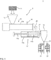
- the foam molding machine 1 comprises a resin supplying machine 2, a T-die 18, and molds 21 and 22.
- the resin supplying machine 2 comprises a hopper 12, an extruder 13, an injector 16, and an accumulator 17.
- the extruder 13 and the accumulator 17 are connected via a connecting tube 25.
- the accumulator 17 and the T-die 18 are connected via a connecting tube 27.
- the hopper 12 is used to charge the raw material resin 11 into the cylinder 13a of the extruder 13.
- the raw material resin is, for example, a thermoplastic resin such as polyolefin.
- polyolefin low density polyethylene, linear low density polyethylene, high density polyethylene, polypropylene, ethylene-propylene copolymer, and mixtures thereof can be mentioned.
- the molten resin is transferred towards the tip of the cylinder 13a by the rotation of a screw arranged in the cylinder 13a.
- the screw is arranged in the cylinder 13a, and the rotation thereof allows to knead and transfer the molten resin.
- a gear device is provided at the rear anchor of the screw to rotationally drive the screw.
- the number of screws arranged in the cylinder 13a can be one and can be two or more.
- An injector 16 is provided with the cylinder 13a to inject a foaming agent into the cylinder 13a.
- a physical foaming agent such as air, carbon dioxide gas, nitrogen gas, water, and the like; and organic physical foaming agent such as butane, pentane, hexane, dichloromethane, dichloroethane and the like; and supercritical fluid thereof can be used.
- the supercritical fluid it is preferable to prepare the supercritical fluid using carbon dioxide, nitrogen, and the like.
- supercritical fluid When nitrogen is used, supercritical fluid can be obtained with the critical temperature of -149.1°C and critical pressure of 3.4 MPa or more. When carbon dioxide is used, supercritical fluid can be obtained with the critical temperature of 31°C and critical pressure of 7.4 MPa or more.
- the chemical foaming agent those which can generate carbon dioxide gas by the reaction of acid (for example, citric acid or salt thereof) and base (for example, sodium bicarbonate) can be mentioned.
- the chemical foaming agent can be charged from the hopper 12 instead of being injected from the injector 16.
- the foam resin obtained by melting and kneading the raw material resin and the foaming agent is extruded from the resin extruding opening of the cylinder 13a, and then injected into the accumulator 17 via the connecting tube 25.
- the accumulator 17 is provided with a cylinder 17a and a piston 17b, the piston 17b capable of sliding in the cylinder 17a.
- the foam resin can be contained in the cylinder 17a.
- the foam resin sheet 23 is introduced between the first mold 21 and the second mold 22.
- the first mold 21 is provided with a plurality of reduced pressure suction holes 21a, and can shape the foam resin sheet 23 so as to follow the shape of the cavity 21b of the first mold 21 by reduced pressure suction.
- the cavity 21b has a recessed portion 21c, and a pinch off portion 21d surrounds the recessed portion 21c.
- the second mold 22 is provided with a plurality of reduced pressure suction holes 22a, and can shape the foam resin sheet 23 so as to follow the shape of the cavity 22b of the second mold 22 by reduced pressure suction.
- the cavity 22b has a convex portion 22c which can come into the recessed portion 21c, and a pinch off portion 22d surrounds the convex portion 22c.
- the cavity 22b of the second mold 22 can have the recessed portion and the cavity 21b of the first mold 21 can have the convex portion which can come into the recessed portion.
- the method for manufacturing the foam molded body according to one embodiment of the present invention comprises an arranging step and an expanding step. Detailed explanation will be given hereinafter.
- one sheet of a foam resin sheet 23 is arranged between the molds 21 and 22, the foam resin sheet 23 being formed by extruding and dangling a molten foam resin from the slit of the T-die 18.
- a direct vacuum forming which uses the foam resin sheet 23 as extruded from the T-die 18 is performed. Accordingly, the foam resin sheet 23 would not solidify due to being cooled to room temperature before forming, and heating of the solidified foam resin sheet 23 before forming would not be performed.
- the foam resin sheet 23 of the present embodiment has a substantially uniform temperature immediately after being extruded from the slit, and is then gradually cooled from its surface by the atmosphere during dangling. Accordingly, influence of the atmosphere to cool the foam resin sheet 23 becomes small towards the center of the foam resin sheet 23 in the thickness direction. Therefore, the foam resin sheet 23 of the present embodiment has higher temperature and lower viscosity towards the center of the foam resin sheet 23 in the thickness direction.
- the thickness of the foam resin sheet 23 is not particularly limited, and is 0.5 to 5 mm for example, preferably 1 to 3 mm.
- the thickness is, particularly for example, 0.5, 1, 1.5, 2, 2.5, 3, 3.5, 4, 4.5, or 5 mm, and can be in the range between the two values exemplified herein.
- the molds 21 and 22 are arranged close to each other so that a gap G having a larger thickness than the thickness of the foam resin sheet 23 is provided, and the foam resin sheet 23 is subjected to reduced pressure suction by both of the molds 21 and 22, thereby expanding the foam resin sheet 23 to have the thickness of the gap G.
- the molds 21 and 22 are provided with pinch off portions 21d and 22d, respectively.
- the space surrounded by the pinch off portions 21d and 22d becomes a closed space S.
- the portion 23a within the closed space S becomes the foam molded body 24.
- the portion outside the closed space S becomes the burr 23b.
- the cavities 21b and 22b of the molds 21 and 22 are structured so that the thickness of the gap G between the molds 21 and 22 is substantially constant throughout the entirety of the portion which becomes the foam molded body 24 (that is, the portion within the closed space S) in the foam resin sheet 23.
- the foam resin sheet 23 is subjected to reduced pressure suction by the molds 21 and 22 in this condition, the foam resin sheet 23 expands to the thickness of the gap G, thereby forming the foam molded body 24.
- the pinch off portions 21d and 22d are not essential constitutions, and the molds 21 and 22 can be closened to each other without contacting with each other, thereby forming a gap G between the molds 21 and 22.
- the thickness of the gap G is not particularly limited, and is preferably 1.1 to 3.0 times the thickness of the foam resin sheet 23. (thickness of gap G) / (thickness of foam resin sheet 23) is, particularly for example, 1.1, 1.2, 1.3, 1.4, 1.5, 1.6, 1.7, 1.8, 1.9, 2.0, 2.1, 2.2, 2.3, 2.4, 2.5, 2.6, 2.7, 2.8 or 3.0, and can be in the range between the two values exemplified herein.
- reduced pressure suction by the first mold 21 can be started antecedently, reduced pressure suction by the second mold 22 can be started antecedently, and reduced pressure suction by the molds 21 and 22 can be started simultaneously. Further, reduced pressure suction by the first mold 21 can be terminated antecedently, reduced pressure suction by the second mold 22 can be terminated antecedently, and reduced pressure suction by the molds 21 and 22 can be terminated simultaneously. Reduced pressure suction by the molds 21 and 22 can be started before the molds 21 and 22 are closened to each other or can be started after the molds are closened to each other.
- foaming of the foam resin sheet 23 is enhanced, and thus the foam resin sheet 23 expands. Since the foam resin sheet 23 has lowest viscosity (highest fluidity) at the central portion of the foam resin sheet 23 in the thickness direction, foaming at the central portion in the thickness direction is especially enhanced, thereby expanding the foam resin sheet 23. As a result, a foam molded body 24 in which the average bubble diameter in the layer at the central portion of the foam resin sheet 23 in the thickness direction (central layer) is large and the average bubble diameter at the skin layer near the surface is small is obtained. Since such foam molded body 24 has a sandwich structure in which the central layer having larger average bubble diameter is sandwiched by skin layers having smaller average bubble diameter, the foam molded body 24 is light in weight and high in rigidity.
- the foam molded body 24 obtained by the method of the present embodiment has a larger average bubble diameter at the central layer than the average bubble diameter at the skin layer (surface layer).
- the skin layer is a layer located from a surface of the foam molded body 24 to 10% of the foam molded body 24 in a thickness direction of the foam molded body 24, and the central layer is a layer located from 25 to 50% of the foam molded body 24 in the thickness direction of the foam molded body 24 from the surface.
- the ratio of (average bubble diameter of central layer) / (average bubble diameter of skin layer) is not particularly limited, and is 1.2 to 10 for example.
- the ratio is, particularly for example, 1.2, 1.3, 1.4, 1.5, 1.6, 1.7, 1.8, 1.9, 2, 2.5, 3, 3.5, 4, 4.5, 5, 5.5, 6, 7, 8, 9 or 10, and can be in the range between the two values exemplified herein.
- the average bubble diameter of the foam molded body 24 in the entirety of the thickness direction or the foam molded body 24 is, for example, 100 to 2000 ⁇ m.
- the average bubble diameter is, particularly for example, 100, 200, 300, 400, 500, 600, 700, 800, 900, 1000, 1500 or 2000 ⁇ m, and can be in the range between the two values exemplified herein.
- the average bubble diameter of the skin layer is, for example, 80 to 500 ⁇ m.
- the average bubble diameter is, particularly for example, 80, 100, 150, 200, 250, 300, 350, 400, 450 or 500 ⁇ m, and can be in the range between the two values exemplified herein.
- the average bubble diameter of the central layer is, for example, 100 to 2000 ⁇ m.
- the average bubble diameter is, particularly for example, 100, 200, 300, 400, 500, 600, 700, 800, 900, 1000, 1100, 1200, 1300, 1400, 1500, 1600, 1700, 1800, 1900 or 2000 ⁇ m, and can be in the range between the two values exemplified herein.
- the average bubble diameter is measured in accordance with the following method.
- a sectional picture of the foam molded body 24 is taken by magnification of 50 times.
- the number of bubbles through which the base lines penetrate are counted for the layer under measurement (skin layer, central layer, or entirely in the thickness direction).
- Maximum length in the thickness direction (length at a portion where the length in the thickness direction becomes maximum) is measured for each of the bubbles.
- the number of bubbles through which the base line R penetrate is 6 in the central layer, and the maximum length in the thickness direction of each of the bubbles are L1 to L6. Accordingly, in this example, the provisional average bubble diameter of the central layer is calculated by (L1 + L2 + L3 + L4 + L5 + L6) / 6.
- the expanding step is preferably performed by carrying out the first suction step, mold closening step, and the second suction step in this order.
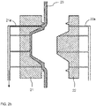
- the foam resin sheet is subjected to reduced pressure suction by the first mold 21, thereby shaping the foam resin sheet 23 to follow the shape of the cavity 21b of the first mold 21.
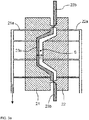
- the mold closening step as shown in Fig. 3a , molds 21 and 22 are closened to each other so as to provide a gap G between the molds 21 and 22.
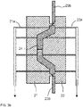
- the foam resin sheet 23 is subjected to reduced pressure suction by the molds 21 and 22 to expand the foam resin sheet 23 to the thickness of the gap G.
- the foam resin sheet 23 When the reduced pressure suction by the molds 21 and 22 are started after the molds 21 and 22 are closened to each other, the foam resin sheet 23 would come in contact with the convex portion 22c of the mold 22 before the foam resin sheet 23 is shaped.
- the temperature of the molds 21 and 22 are lower than the temperature of the foam resin sheet 23, and thus when the foam resin sheet 23 comes in contact with the convex portion 22c of the mold 22, the foam resin sheet 23 is cooled and its viscosity would increase. Accordingly, accuracy of the foam resin sheet 23 to follow the shape of the cavities 21b and 22b of the molds 21 and 22 would degrade.
- the expanding step is carried out by performing the first suction step, mold closening step, and the second suction step in this order
- the foam resin sheet 23 contacting the molds 21 and 22 before being shaped to follow the shape of the cavity 21b of the first mold 21 would be suppressed to minimum. Accordingly, the viscosity increase of the foam resin sheet 23 would be suppressed, and the foam resin sheet 23 can be allowed to follow the cavities of the molds 21 and 22 with high accuracy.
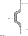
- the molds 21 and 22 are opened as shown in Fig. 4a , and the foam molded body 24 with burr 23b is taken out.
- the burr 23b is cut off to give the foam molded body 24 as shown in Fig. 4b .
- the foam resin sheet 23 can follow the shape of the cavity of the mold with high accuracy even when the thickness of the foam resin sheet 23 is thick, and a foam molded body 24 which is light in weight and high in rigidity can be manufactured.
- the foam molded body 24 of the present invention is light in weight and high in rigidity, the foam molded body 24 can be used in various applications which consider such characteristics favorable.
- a covering material structured with a ventilation member such as a non-woven fabric can be provided on one side or both sides of the foam molded body 24.
- the covering material can be integrally molded onto one side or both sides of the foam molded body 24 by performing reduced pressure suction of the foam resin sheet 23 by the molds 21 and 22 in a similar manner as above, in a condition where the covering material is arranged at least at either one of between the foam resin sheet 23 and the mold 21 and between the foam resin sheet 23 and the mold 22.
- the foam molded body 24 of the present invention can, for example, be utilized as interior member of a car such as door trim, ceiling material and the like; board such as luggage floor board and the like; duct; engine under cover; and the like.
- the foam molded body 24 is utilized as the interior member of a car, it is preferable to integrally mold the covering material onto one side of the foam molded body 24.
- the ceiling material was structured by adhering the covering material onto a polyurethane sheet by an adhesive and the like.
- the covering material can be integrally molded onto the foam molded body 24 and thus the burden to adhere the covering material can be omitted.
- the covering material can be fixed onto the foam molded body 24 by an anchor effect (effect to fix the covering material onto the resin by allowing the resin to permeate into the covering material), rather than using the adhesive.
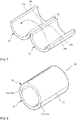
- the duct 30 can be formed by joining a pair of duct half bodies 31 and 32 to form a cylindrical shape.
- the duct half bodies 31 and 32 are coupled with each other at the hinge portion 33.
- the duct half bodies 31 and 32 and the hinge portion 33 can be integrally molded by the manufacturing method described above.
- joining surfaces 31a and 32a are provided respectively.
- the duct half bodies 31 and 32 are relatively rotated about the hinge portion 33, and then the duct half bodies 31 and 32 are joined with each other in a condition where the joining surfaces 31a and 32a are in contact with each other, thereby forming the duct 30.
- the duct half bodies 31 and 32 can be joined using a screw, a rivet, a tucker and the like.
- the foam molded product (door trim) was manufactured.
- polypropylene based resin A product name "Daploy WB140", available from Brealis AG
- polypropylene based resin B product name "NOVATEC PP ⁇ BC4BSW”, available from Japan Polypropylene Corporation
- LDPE base master batch containing sodium hydrogen carbonate based foaming agent by 20 wt%
- the foam resin sheet 23 formed under the afore-mentioned conditions was arranged between the molds 21 and 22. Subsequently, the foam resin sheet 23 was subjected to reduced pressure suction by the first mold 21, thereby shaping the foam resin sheet 23 to follow the shape of the cavity of the first mold 21. Then, in a condition where the molds 21 and 22 are closened to each other so that the gap G between the molds 21 and 22 is 3 mm, foam resin sheet 23 was subjected to reduced pressure suction by the molds 21 and 22, thereby allowing the foam resin sheet 23 to expand until the thickness of the foam resin sheet 23 reaches the thickness of the gap G. Accordingly, foam molded body 24 was obtained. The reduced pressure suction by the molds 21 and 22 was carried out under the pressure of - 0.1 MPa.
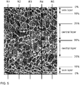
- the foam molded body 24 was light in weight and had high rigidity compared to general foam molded body. Sectional picture of the foam molded body 24 is shown in Fig. 5 .
- the average bubble diameter of the foam molded body 24 was measured for the skin layer and the central layer, and were 132.3 ⁇ m and 184.2 ⁇ m, respectively.
- the ratio of (average bubble diameter of central layer) / (average bubble diameter of skin layer) was 1.39.
Landscapes
- Engineering & Computer Science (AREA)
- Mechanical Engineering (AREA)
- Manufacturing & Machinery (AREA)
- Blow-Moulding Or Thermoforming Of Plastics Or The Like (AREA)
- Molding Of Porous Articles (AREA)
- Moulds For Moulding Plastics Or The Like (AREA)
Abstract
Description
- The present invention relates to a method for manufacturing a foam molded body such as an interior member of a car (door trim and ceiling material for example), a board such as a luggage floor board, a duct, an engine under cover, and the like.
-
Patent Literature 1 discloses a technique in which one foam resin sheet is reheated, and then the softened foam resin sheet is arranged between a pair of split molds, followed by suction from the molds on both sides under reduced pressure. Accordingly, the foam resin sheet undergoes a secondary foaming to give a thick portion. - [Patent Literature 1]
JP 2001-310380A - In the technique of
Patent Literature 1, a foam resin sheet of ambient temperature is prepared before-hand, and is softened by reheating by radiant heat such as infrared heater when forming is carried out. In such method, problem seldom occur when the foam resin sheet is extremely thin, however, as the thickness of the foam resin sheet increases, softening of the central portion of the foam resin sheet in the thickness direction becomes insufficient, thereby resulting in degradation of shaping characteristic and it becomes difficult for the foam resin sheet to follow the shape of the cavity of the mold. - The present invention has been made by taking the afore-mentioned circumstances into consideration. The present invention provides a method for manufacturing a foam molded body which can allow the foam resin sheet to follow the shape of the cavity of the mold with high accuracy even when the thickness of the foam resin sheet is thick.
- According to the present invention, a method for manufacturing a foam molded body, comprising the steps of: an arranging step to arrange one sheet of a foam resin sheet between a first mold and a second mold, the foam resin sheet being formed by extruding and dangling a molten foam resin from a slit; and an expanding step to expand the foam resin sheet by subjecting the foam resin sheet to a reduced pressure suction in a condition where the first mold and the second mold are closened to provide a gap between the first mold and the second mold, the gap having a thickness larger than a thickness of the foam resin sheet, thereby expanding the foam resin sheet to have the thickness of the gap, is provided.
- In the present invention, rather than using a softened foam resin sheet obtained by reheating the foam resin sheet of ambient temperature, one sheet of a foam resin sheet formed by extruding and dangling a molten foam resin from a slit is used. In the foam resin sheet thus formed, influence of cooling by atmosphere becomes small towards the center of the foam resin sheet with respect to the thickness direction. Therefore, the temperature rises and the viscosity decreases towards the center of the foam resin sheet with respect to the thickness direction. Accordingly, in the present invention, the foam resin sheet can follow the shape of the cavity of the mold of with high accuracy even when the thickness of the foam resin sheet is thick.
- Further, in the conventional technique, when the softening at the central portion of the foam resin sheet is insufficient, secondary foaming would mainly occur at the vicinity of the surface of the foam resin sheet when reduced pressure suction of the foam resin sheet is performed from both of the pair of molds. Accordingly, the rigidity at the thick portion tended to become insufficient. On the other hand, in the present invention, the viscosity would decrease towards the center of the foam resin sheet with respect to the thickness direction. Accordingly, when the foam resin sheet undergoes reduced pressure suction from both of the pair of molds, foaming is enhanced mainly at the vicinity of the center of the foam resin sheet, thereby expanding the foam resin sheet. Therefore, in the present invention, the foam molded body is structured so that a layer at the vicinity of the center of the foam resin sheet in the thickness direction (central layer) has a large average bubble diameter, and a skin layer at the vicinity of the surface of the foam resin sheet has a small average bubble diameter. Since such foam molded body has a sandwich structure in which the central layer having larger average bubble diameter is sandwiched by skin layers having smaller average bubble diameter, the foam molded body is light in weight and high in rigidity.
- Accordingly, in the present invention, a foam resin sheet can follow the shape of the cavity of the mold with high accuracy even when the thickness of the foam resin sheet is thick, and a foam molded body which is light in weight and high in rigidity can be manufactured.
- Hereinafter, various embodiments of the present invention will be described. The embodiments described hereinafter can be combined with each other.
- Preferably, the expanding step comprises performing a first suction step, a mold closening step, and a second suction step in this order; the first suction step comprises subjecting the foam resin sheet to reduced pressure suction by the first mold, thereby shaping the foam resin sheet to follow a shape of a cavity of the first mold; the mold closening step comprises closening the first mold and the second mold to each other to provide the gap in between the first mold and the second mold; the second suction step comprises subjecting the foam resin sheet to reduced pressure suction by the first mold and the second mold, thereby expanding the foam resin sheet to have the thickness of the gap.
- Preferably, an entirety of a portion, which gives the foam molded body, of the foam resin sheet is expanded in the expanding step.
- Preferably, the cavity of the first mold and a cavity of the second mold are structured so that the gap in the portion, which gives the foam molded body of the foam resin sheet is substantially constant.
- Preferably, the cavity of the first mold has a shape with a recessed portion, and the cavity of the second mold has a shape with a convex portion which comes into the recessed portion.
- Preferably, the gap has a thickness of 1.1 to 3.0 times of the thickness of the foam resin sheet.
- According to another aspect of the present invention, a foam molded body comprising a central layer and skin layers provided on both sides of the central layer; wherein: the skin layer is a layer located from a surface of the foam molded body to 10% of the foam molded body in a thickness direction of the foam molded body, and the central layer is a layer located from 25 to 50% of the foam molded body in the thickness direction of the foam molded body from the surface; and an average bubble diameter of the central layer is larger than an average bubble diameter of the skin layer, is provided.
- Preferably, a ratio of (the average bubble diameter of the central layer) / (the average bubble diameter of the skin layer) is 1.2 to 10.
-
-
Fig. 1 shows one example of afoam molding machine 1 which can be used in the manufacturing method of the foam molded body according to one embodiment of the present invention. -
Fig. 2a is an enlarged sectional view of the vicinity of thefirst mold 21, thesecond mold 22, and thefoam resin sheet 23 ofFig. 1 . -
Fig. 2b is a sectional view corresponding toFig. 2a , showing a condition in which thefoam resin sheet 23 is subjected to reduced pressure suction by thefirst mold 21 from the condition shown inFig. 2a , thereby shaping thefoam resin sheet 23 to follow the shape ofcavity 21b of thefirst mold 21. -
Fig. 3a is a sectional view corresponding toFig. 2a , showing a condition in which themolds Fig. 2b . -
Fig. 3b is a sectional view corresponding toFig. 2a , showing a condition in which thefoam resin sheet 23 is subjected to reduced pressure suction by thesecond mold 22 from the condition shown inFig. 3a , thereby allowing thefoam resin sheet 23 to expand to the thickness of the gap G between themolds -
Fig. 4a is a sectional view corresponding toFig. 2a , showing a foam moldedbody 24 with aburr 23b obtained in the step ofFig. 3b . -
Fig. 4b is a sectional view corresponding toFig. 2a , showing a condition in which theburr 23b is removed from the condition shown inFig. 4a . -
Fig. 5 is a sectional picture of the foam moldedbody 24 obtained in the embodiment of the present invention. -
Fig. 6 shows one example of a configuration of the bubbles for explaining the calculation method of a provisional average bubble diameter. -
Fig. 7 is a perspective view showing the structure ofduct half bodies hinge portion 33. -
Fig. 8 is a perspective view showing theduct 30 formed by joining theduct half bodies - Hereinafter, various embodiments of the present invention will be described. Various distinctive features shown in the following embodiments can be combined with each other. In addition, an invention can be established independently for each of the distinctive features.
- First, with reference to
Fig. 1 to Fig. 4 , thefoam molding machine 1 which can be used in carrying out the manufacturing method of the foam molded body of one embodiment of the present invention will be explained. Thefoam molding machine 1 comprises aresin supplying machine 2, a T-die 18, andmolds resin supplying machine 2 comprises ahopper 12, anextruder 13, aninjector 16, and anaccumulator 17. Theextruder 13 and theaccumulator 17 are connected via a connectingtube 25. Theaccumulator 17 and the T-die 18 are connected via a connectingtube 27. - Hereinafter, each of the configuration is explained in detail.
- The
hopper 12 is used to charge theraw material resin 11 into thecylinder 13a of theextruder 13. There is no particular limitation regarding the form of theraw material resin 11, however, it is usually a pellet. The raw material resin is, for example, a thermoplastic resin such as polyolefin. As the polyolefin, low density polyethylene, linear low density polyethylene, high density polyethylene, polypropylene, ethylene-propylene copolymer, and mixtures thereof can be mentioned. After theraw material resin 11 is charged from thehopper 12 into thecylinder 13a, theraw material resin 11 is heated in thecylinder 13a, thereby melting to give a molten resin. Here, the molten resin is transferred towards the tip of thecylinder 13a by the rotation of a screw arranged in thecylinder 13a. The screw is arranged in thecylinder 13a, and the rotation thereof allows to knead and transfer the molten resin. At the rear anchor of the screw, a gear device is provided to rotationally drive the screw. The number of screws arranged in thecylinder 13a can be one and can be two or more. - An
injector 16 is provided with thecylinder 13a to inject a foaming agent into thecylinder 13a. As the foaming agent injected from theinjector 16, a physical foaming agent, a chemical foaming agent, and a mixture thereof can be mentioned. Here, the physical foaming agent is preferable. As the physical foaming agent, an inorganic physical foaming agent such as air, carbon dioxide gas, nitrogen gas, water, and the like; and organic physical foaming agent such as butane, pentane, hexane, dichloromethane, dichloroethane and the like; and supercritical fluid thereof can be used. As the supercritical fluid, it is preferable to prepare the supercritical fluid using carbon dioxide, nitrogen, and the like. When nitrogen is used, supercritical fluid can be obtained with the critical temperature of -149.1°C and critical pressure of 3.4 MPa or more. When carbon dioxide is used, supercritical fluid can be obtained with the critical temperature of 31°C and critical pressure of 7.4 MPa or more. As the chemical foaming agent, those which can generate carbon dioxide gas by the reaction of acid (for example, citric acid or salt thereof) and base (for example, sodium bicarbonate) can be mentioned. The chemical foaming agent can be charged from thehopper 12 instead of being injected from theinjector 16. - The foam resin obtained by melting and kneading the raw material resin and the foaming agent is extruded from the resin extruding opening of the
cylinder 13a, and then injected into theaccumulator 17 via the connectingtube 25. Theaccumulator 17 is provided with acylinder 17a and apiston 17b, thepiston 17b capable of sliding in thecylinder 17a. The foam resin can be contained in thecylinder 17a. By moving thepiston 17b after a prescribed amount of the foam resin is contained in thecylinder 17a, the foam resin is extruded from the slit provided in the T-die 18 via the connectingtube 27, thereby dangling the foam resin to form thefoam resin sheet 23. - The
foam resin sheet 23 is introduced between thefirst mold 21 and thesecond mold 22. As shown inFig 1 to Fig. 3 , thefirst mold 21 is provided with a plurality of reducedpressure suction holes 21a, and can shape thefoam resin sheet 23 so as to follow the shape of thecavity 21b of thefirst mold 21 by reduced pressure suction. Thecavity 21b has a recessedportion 21c, and a pinch offportion 21d surrounds the recessedportion 21c. Thesecond mold 22 is provided with a plurality of reducedpressure suction holes 22a, and can shape thefoam resin sheet 23 so as to follow the shape of thecavity 22b of thesecond mold 22 by reduced pressure suction. Thecavity 22b has aconvex portion 22c which can come into the recessedportion 21c, and a pinch offportion 22d surrounds theconvex portion 22c. Here, thecavity 22b of thesecond mold 22 can have the recessed portion and thecavity 21b of thefirst mold 21 can have the convex portion which can come into the recessed portion. - Here, with reference to
Fig. 2 to Fig. 4 , the method for manufacturing the foam molded body according to one embodiment of the present invention will be described. The method of the present embodiment comprises an arranging step and an expanding step. Detailed explanation will be given hereinafter. - In this step, as shown in
Fig. 1 andFig. 2a , one sheet of afoam resin sheet 23 is arranged between themolds foam resin sheet 23 being formed by extruding and dangling a molten foam resin from the slit of the T-die 18. In the present embodiment, a direct vacuum forming which uses thefoam resin sheet 23 as extruded from the T-die 18 is performed. Accordingly, thefoam resin sheet 23 would not solidify due to being cooled to room temperature before forming, and heating of the solidifiedfoam resin sheet 23 before forming would not be performed. Here, thefoam resin sheet 23 of the present embodiment has a substantially uniform temperature immediately after being extruded from the slit, and is then gradually cooled from its surface by the atmosphere during dangling. Accordingly, influence of the atmosphere to cool thefoam resin sheet 23 becomes small towards the center of thefoam resin sheet 23 in the thickness direction. Therefore, thefoam resin sheet 23 of the present embodiment has higher temperature and lower viscosity towards the center of thefoam resin sheet 23 in the thickness direction. The thickness of thefoam resin sheet 23 is not particularly limited, and is 0.5 to 5 mm for example, preferably 1 to 3 mm. The thickness is, particularly for example, 0.5, 1, 1.5, 2, 2.5, 3, 3.5, 4, 4.5, or 5 mm, and can be in the range between the two values exemplified herein. - In this step, as shown in
Fig. 2b to Fig. 3b , themolds foam resin sheet 23 is provided, and thefoam resin sheet 23 is subjected to reduced pressure suction by both of themolds foam resin sheet 23 to have the thickness of the gap G. - In the present embodiment, the
molds portions molds portions portions foam resin sheet 23, theportion 23a within the closed space S becomes the foam moldedbody 24. On the other hand, in thefoam resin sheet 23, the portion outside the closed space S becomes theburr 23b. - The
cavities molds molds foam resin sheet 23. When thefoam resin sheet 23 is subjected to reduced pressure suction by themolds foam resin sheet 23 expands to the thickness of the gap G, thereby forming the foam moldedbody 24. Here, the pinch offportions molds molds molds portions foam resin sheet 23 can be expanded easily. - The thickness of the gap G is not particularly limited, and is preferably 1.1 to 3.0 times the thickness of the
foam resin sheet 23. (thickness of gap G) / (thickness of foam resin sheet 23) is, particularly for example, 1.1, 1.2, 1.3, 1.4, 1.5, 1.6, 1.7, 1.8, 1.9, 2.0, 2.1, 2.2, 2.3, 2.4, 2.5, 2.6, 2.7, 2.8 or 3.0, and can be in the range between the two values exemplified herein. - Regarding the reduced pressure suction by the
molds first mold 21 can be started antecedently, reduced pressure suction by thesecond mold 22 can be started antecedently, and reduced pressure suction by themolds first mold 21 can be terminated antecedently, reduced pressure suction by thesecond mold 22 can be terminated antecedently, and reduced pressure suction by themolds molds molds - When the
foam resin sheet 23 is subjected to reduced pressure suction by both of themolds foam resin sheet 23 is enhanced, and thus thefoam resin sheet 23 expands. Since thefoam resin sheet 23 has lowest viscosity (highest fluidity) at the central portion of thefoam resin sheet 23 in the thickness direction, foaming at the central portion in the thickness direction is especially enhanced, thereby expanding thefoam resin sheet 23. As a result, a foam moldedbody 24 in which the average bubble diameter in the layer at the central portion of thefoam resin sheet 23 in the thickness direction (central layer) is large and the average bubble diameter at the skin layer near the surface is small is obtained. Since such foam moldedbody 24 has a sandwich structure in which the central layer having larger average bubble diameter is sandwiched by skin layers having smaller average bubble diameter, the foam moldedbody 24 is light in weight and high in rigidity. - As shown in the sectional picture of
Fig. 5 , the foam moldedbody 24 obtained by the method of the present embodiment has a larger average bubble diameter at the central layer than the average bubble diameter at the skin layer (surface layer). Here, in the foam moldedbody 24, the skin layer is a layer located from a surface of the foam moldedbody 24 to 10% of the foam moldedbody 24 in a thickness direction of the foam moldedbody 24, and the central layer is a layer located from 25 to 50% of the foam moldedbody 24 in the thickness direction of the foam moldedbody 24 from the surface. The ratio of (average bubble diameter of central layer) / (average bubble diameter of skin layer) is not particularly limited, and is 1.2 to 10 for example. The ratio is, particularly for example, 1.2, 1.3, 1.4, 1.5, 1.6, 1.7, 1.8, 1.9, 2, 2.5, 3, 3.5, 4, 4.5, 5, 5.5, 6, 7, 8, 9 or 10, and can be in the range between the two values exemplified herein. - The average bubble diameter of the foam molded
body 24 in the entirety of the thickness direction or the foam moldedbody 24 is, for example, 100 to 2000 µm. The average bubble diameter is, particularly for example, 100, 200, 300, 400, 500, 600, 700, 800, 900, 1000, 1500 or 2000 µm, and can be in the range between the two values exemplified herein. The average bubble diameter of the skin layer is, for example, 80 to 500 µm. The average bubble diameter is, particularly for example, 80, 100, 150, 200, 250, 300, 350, 400, 450 or 500 µm, and can be in the range between the two values exemplified herein. The average bubble diameter of the central layer is, for example, 100 to 2000 µm. The average bubble diameter is, particularly for example, 100, 200, 300, 400, 500, 600, 700, 800, 900, 1000, 1100, 1200, 1300, 1400, 1500, 1600, 1700, 1800, 1900 or 2000 µm, and can be in the range between the two values exemplified herein. - The average bubble diameter is measured in accordance with the following method.
- First, as shown in
Fig. 5 , a sectional picture of the foam moldedbody 24 is taken by magnification of 50 times. - Then, five base lines of R1 to R5 which elongate in the thickness direction of the foam molded
body 24 are drawn. The distance between the base lines are 500 µm. - With each of the base lines, the number of bubbles through which the base lines penetrate are counted for the layer under measurement (skin layer, central layer, or entirely in the thickness direction).
- Maximum length in the thickness direction (length at a portion where the length in the thickness direction becomes maximum) is measured for each of the bubbles.
- Provisional average bubble diameter is calculated for each of the base lines in accordance with formula (1). Further, arithmetical mean is calculated with the provisional average bubble diameter calculated for each of the base lines, thereby obtaining the average bubble diameter.

- In the example shown in
Fig. 6 , the number of bubbles through which the base line R penetrate is 6 in the central layer, and the maximum length in the thickness direction of each of the bubbles are L1 to L6. Accordingly, in this example, the provisional average bubble diameter of the central layer is calculated by (L1 + L2 + L3 + L4 + L5 + L6) / 6. - The expanding step is preferably performed by carrying out the first suction step, mold closening step, and the second suction step in this order. In the first suction step, as shown in
Fig. 2b , the foam resin sheet is subjected to reduced pressure suction by thefirst mold 21, thereby shaping thefoam resin sheet 23 to follow the shape of thecavity 21b of thefirst mold 21. In the mold closening step, as shown inFig. 3a ,molds molds Fig. 3b , thefoam resin sheet 23 is subjected to reduced pressure suction by themolds foam resin sheet 23 to the thickness of the gap G. - When the reduced pressure suction by the
molds molds foam resin sheet 23 would come in contact with theconvex portion 22c of themold 22 before thefoam resin sheet 23 is shaped. Usually, the temperature of themolds foam resin sheet 23, and thus when thefoam resin sheet 23 comes in contact with theconvex portion 22c of themold 22, thefoam resin sheet 23 is cooled and its viscosity would increase. Accordingly, accuracy of thefoam resin sheet 23 to follow the shape of thecavities molds foam resin sheet 23 contacting themolds cavity 21b of thefirst mold 21 would be suppressed to minimum. Accordingly, the viscosity increase of thefoam resin sheet 23 would be suppressed, and thefoam resin sheet 23 can be allowed to follow the cavities of themolds - After the expanding step, the
molds Fig. 4a , and the foam moldedbody 24 withburr 23b is taken out. Theburr 23b is cut off to give the foam moldedbody 24 as shown inFig. 4b . - As discussed, with the method of the present embodiment, the
foam resin sheet 23 can follow the shape of the cavity of the mold with high accuracy even when the thickness of thefoam resin sheet 23 is thick, and a foam moldedbody 24 which is light in weight and high in rigidity can be manufactured. - Since the foam molded
body 24 of the present invention is light in weight and high in rigidity, the foam moldedbody 24 can be used in various applications which consider such characteristics favorable. In addition, a covering material structured with a ventilation member such as a non-woven fabric can be provided on one side or both sides of the foam moldedbody 24. The covering material can be integrally molded onto one side or both sides of the foam moldedbody 24 by performing reduced pressure suction of thefoam resin sheet 23 by themolds foam resin sheet 23 and themold 21 and between thefoam resin sheet 23 and themold 22. - The foam molded
body 24 of the present invention can, for example, be utilized as interior member of a car such as door trim, ceiling material and the like; board such as luggage floor board and the like; duct; engine under cover; and the like. When the foam moldedbody 24 is utilized as the interior member of a car, it is preferable to integrally mold the covering material onto one side of the foam moldedbody 24. For example, in the conventional technique, the ceiling material was structured by adhering the covering material onto a polyurethane sheet by an adhesive and the like. In the present invention, the covering material can be integrally molded onto the foam moldedbody 24 and thus the burden to adhere the covering material can be omitted. In addition, the covering material can be fixed onto the foam moldedbody 24 by an anchor effect (effect to fix the covering material onto the resin by allowing the resin to permeate into the covering material), rather than using the adhesive. - As shown in
Fig. 7 to Fig. 8 , theduct 30 can be formed by joining a pair ofduct half bodies duct half bodies hinge portion 33. Theduct half bodies hinge portion 33 can be integrally molded by the manufacturing method described above. To each of theduct half bodies surfaces duct half bodies hinge portion 33, and then theduct half bodies surfaces duct 30. Theduct half bodies - Using the
foam molding machine 1 shown inFig. 1 , the foam molded product (door trim) was manufactured. The inner diameter of thecylinder 13a of theextruder 13 was 50 mm, and equation of L/D=34 was satisfied. As the raw material resin, polypropylene based resin A (product name "Daploy WB140", available from Brealis AG) and polypropylene based resin B (product name "NOVATEC PP·BC4BSW", available from Japan Polypropylene Corporation) were combined by a mass ratio of 60:40, and 1.0 parts by weight of LDPE base master batch containing sodium hydrogen carbonate based foaming agent by 20 wt% (product name "FINECELL MASTER P0217K", available from Dainichiseika Color & Chemicals Mfg. Co., Ltd.) as nucleating agent; and 1.0 parts by weight of LLDPE base master batch containing 40 wt% of carbon black as colorant were added to 100 parts by mass of the resin and used. Temperature of each of the member was controlled so that the temperature of thefoam resin sheet 23 would be in the range of 190 to 200 °C. The rotation number of the screw was set to 60 rpm, and the extrusion amount was set to 20 kg/hr. As the foaming agent, N2 was used and was injected via theinjector 16. Amount of injection was set to 0.4 [wt%] (injection amount of N2 / extrusion amount of resin). T-die 18 was controlled so that thefoam resin sheet 23 would have a thickness of 2 mm. - The
foam resin sheet 23 formed under the afore-mentioned conditions was arranged between themolds foam resin sheet 23 was subjected to reduced pressure suction by thefirst mold 21, thereby shaping thefoam resin sheet 23 to follow the shape of the cavity of thefirst mold 21. Then, in a condition where themolds molds foam resin sheet 23 was subjected to reduced pressure suction by themolds foam resin sheet 23 to expand until the thickness of thefoam resin sheet 23 reaches the thickness of the gap G. Accordingly, foam moldedbody 24 was obtained. The reduced pressure suction by themolds - The foam molded
body 24 was light in weight and had high rigidity compared to general foam molded body. Sectional picture of the foam moldedbody 24 is shown inFig. 5 . The average bubble diameter of the foam moldedbody 24 was measured for the skin layer and the central layer, and were 132.3 µm and 184.2 µm, respectively. The ratio of (average bubble diameter of central layer) / (average bubble diameter of skin layer) was 1.39. - 1: foam molding machine, 2: resin supplying machine, 11: raw material resin, 12: hopper, 13: extruder, 13a: cylinder, 16: injector, 17: accumulator, 17a: cylinder, 17b: piston, 18: T-die, 21: first mold, 21a: reduced pressure suction holes, 21b: cavity, 21c: recessed portion, 21d: pinch off portion, 22: second mold, 22a: reduced pressure suction holes, 22b: cavity, 22c: convex portion, 22d: pinch off portion, 23: foam resin sheet, 23a: portion, 23b: burr, 24: foam molded body, 25: connecting tube, 27: connecting tube, 30: duct, 31 and 32: duct half body, 31a and 32a: joining surface, 33: hinge portion, G: gap, S: closed space
Claims (8)
- A method for manufacturing a foam molded body, comprising the steps of:an arranging step to arrange one sheet of a foam resin sheet between a first mold and a second mold, the foam resin sheet being formed by extruding and dangling a molten foam resin from a slit; andan expanding step to expand the foam resin sheet by subjecting the foam resin sheet to a reduced pressure suction in a condition where the first mold and the second mold are closened to provide a gap between the first mold and the second mold, the gap having a thickness larger than a thickness of the foam resin sheet, thereby expanding the foam resin sheet to have the thickness of the gap.
- The method of Claim 1, wherein:the expanding step comprises performing a first suction step, a mold closening step, and a second suction step in this order;the first suction step comprises subjecting the foam resin sheet to reduced pressure suction by the first mold, thereby shaping the foam resin sheet to follow a shape of a cavity of the first mold;the mold closening step comprises closening the first mold and the second mold to each other to provide the gap in between the first mold and the second mold;the second suction step comprises subjecting the foam resin sheet to reduced pressure suction by the first mold and the second mold, thereby expanding the foam resin sheet to have the thickness of the gap.
- The method of Claim 1 or 2, wherein an entirety of a portion, which gives the foam molded body, of the foam resin sheet is expanded in the expanding step.
- The method of any one of Claims 1 to 3, wherein the cavity of the first mold and a cavity of the second mold are structured so that the gap in the portion, which gives the foam molded body of the foam resin sheet is substantially constant.
- The method of any one of Claims 1 to 4, wherein the cavity of the first mold has a shape with a recessed portion, and the cavity of the second mold has a shape with a convex portion which comes into the recessed portion.
- The method of any one of Claims 1 to 5, wherein the gap has a thickness of 1.1 to 3.0 times of the thickness of the foam resin sheet.
- A foam molded body comprising a central layer and skin layers provided on both sides of the central layer; wherein:the skin layer is a layer located from a surface of the foam molded body to 10% of the foam molded body in a thickness direction of the foam molded body, and the central layer is a layer located from 25 to 50% of the foam molded body in the thickness direction of the foam molded body from the surface; andan average bubble diameter of the central layer is larger than an average bubble diameter of the skin layer.
- The foam molded body of Claim 7, wherein a ratio of (the average bubble diameter of the central layer) / (the average bubble diameter of the skin layer) is 1.2 to 10.
Applications Claiming Priority (3)
| Application Number | Priority Date | Filing Date | Title |
|---|---|---|---|
| JP2016193531 | 2016-09-30 | ||
| JP2017176128A JP7060782B2 (en) | 2016-09-30 | 2017-09-13 | Manufacturing method of foam molded product |
| PCT/JP2017/034274 WO2018062033A1 (en) | 2016-09-30 | 2017-09-22 | Method for manufacturing foam molded body |
Publications (3)
| Publication Number | Publication Date |
|---|---|
| EP3520980A1 true EP3520980A1 (en) | 2019-08-07 |
| EP3520980A4 EP3520980A4 (en) | 2020-01-22 |
| EP3520980B1 EP3520980B1 (en) | 2021-05-12 |
Family
ID=61909295
Family Applications (1)
| Application Number | Title | Priority Date | Filing Date |
|---|---|---|---|
| EP17855987.8A Active EP3520980B1 (en) | 2016-09-30 | 2017-09-22 | Method for manufacturing foam molded body |
Country Status (6)
| Country | Link |
|---|---|
| US (1) | US10940620B2 (en) |
| EP (1) | EP3520980B1 (en) |
| JP (1) | JP7060782B2 (en) |
| KR (1) | KR102326199B1 (en) |
| CN (1) | CN109689332B (en) |
| MX (1) | MX2019003178A (en) |
Cited By (1)
| Publication number | Priority date | Publication date | Assignee | Title |
|---|---|---|---|---|
| EP3990248B1 (en) * | 2019-06-27 | 2025-03-26 | Moxietec, LLC | Polymer foam articles and methods of making polymer foams |
Families Citing this family (3)
| Publication number | Priority date | Publication date | Assignee | Title |
|---|---|---|---|---|
| JP7440743B2 (en) * | 2019-12-26 | 2024-02-29 | キョーラク株式会社 | foam molded body |
| CN115091685B (en) * | 2022-07-21 | 2023-09-05 | 南通超达装备股份有限公司 | Automobile seat foaming mold capable of automatically removing rim charge |
| US20250214287A1 (en) * | 2024-01-03 | 2025-07-03 | King Steel Machinery Co., Ltd. | Injection molding system and method of using the same to manufacture article |
Family Cites Families (14)
| Publication number | Priority date | Publication date | Assignee | Title |
|---|---|---|---|---|
| JP3907077B2 (en) * | 1996-12-04 | 2007-04-18 | 株式会社ジェイエスピー | Polycarbonate resin open cell plate extrusion foam |
| JP2000229349A (en) | 1999-02-12 | 2000-08-22 | Araco Corp | Method for molding laminate |
| JP2000326343A (en) * | 1999-05-20 | 2000-11-28 | Araco Corp | Manufacture of ornamental assembly having graining line |
| JP4456722B2 (en) | 2000-04-28 | 2010-04-28 | 住友化学株式会社 | Method for producing thermoplastic resin foam molding |
| JP4257826B2 (en) * | 2002-09-30 | 2009-04-22 | 株式会社ジェイエスピー | Method for producing polypropylene resin foam molding |
| CA2542367A1 (en) * | 2003-10-17 | 2005-04-28 | Shiina Kasei Co. | Method for producing plastic foamed composite |
| US20060049551A1 (en) | 2004-08-21 | 2006-03-09 | Sumitomo Chemical Company, Limited | Method for producing a thermoplastic resin foamed article |
| JP4539238B2 (en) | 2004-08-31 | 2010-09-08 | 住友化学株式会社 | Vacuum forming method for thermoplastic resin foam sheet |
| JP5597361B2 (en) | 2009-05-21 | 2014-10-01 | 日本ポリプロ株式会社 | Thermoforming sheet comprising polyolefin resin laminated foam sheet and thermoforming article using the same |
| JP5546163B2 (en) | 2009-06-04 | 2014-07-09 | 日本ポリプロ株式会社 | Polyolefin-based resin laminated foam sheet used for thermoforming and thermoformed article using the same |
| JP5554551B2 (en) | 2009-11-30 | 2014-07-23 | キョーラク株式会社 | Method for producing foam molded article |
| JP5755987B2 (en) | 2011-09-27 | 2015-07-29 | Dmノバフォーム株式会社 | Foam, production method thereof and use thereof |
| JP5878034B2 (en) * | 2012-02-16 | 2016-03-08 | キョーラク株式会社 | Foam molding |
| JP6642137B2 (en) | 2015-03-16 | 2020-02-05 | 日本ポリプロ株式会社 | Laminated foam sheet and thermoformed body |
-
2017
- 2017-09-13 JP JP2017176128A patent/JP7060782B2/en active Active
- 2017-09-22 KR KR1020197009515A patent/KR102326199B1/en active Active
- 2017-09-22 EP EP17855987.8A patent/EP3520980B1/en active Active
- 2017-09-22 US US16/336,193 patent/US10940620B2/en active Active
- 2017-09-22 CN CN201780056164.8A patent/CN109689332B/en active Active
- 2017-09-22 MX MX2019003178A patent/MX2019003178A/en unknown
Cited By (1)
| Publication number | Priority date | Publication date | Assignee | Title |
|---|---|---|---|---|
| EP3990248B1 (en) * | 2019-06-27 | 2025-03-26 | Moxietec, LLC | Polymer foam articles and methods of making polymer foams |
Also Published As
| Publication number | Publication date |
|---|---|
| MX2019003178A (en) | 2019-06-06 |
| JP2018058352A (en) | 2018-04-12 |
| KR102326199B1 (en) | 2021-11-15 |
| CN109689332B (en) | 2021-11-02 |
| US20190224891A1 (en) | 2019-07-25 |
| EP3520980A4 (en) | 2020-01-22 |
| JP7060782B2 (en) | 2022-04-27 |
| EP3520980B1 (en) | 2021-05-12 |
| KR20190066010A (en) | 2019-06-12 |
| US10940620B2 (en) | 2021-03-09 |
| CN109689332A (en) | 2019-04-26 |
Similar Documents
| Publication | Publication Date | Title |
|---|---|---|
| EP3520980B1 (en) | Method for manufacturing foam molded body | |
| CN101864107B (en) | Hollow foam moulding body through blow molding | |
| JPH0447615B2 (en) | ||
| JPH10128795A (en) | Molding | |
| EP2835243A2 (en) | Method for producing skin-covered polyolefin resin foamed molded article | |
| JP2001310380A (en) | Thermoplastic resin foam molded article and method for producing the same | |
| EP2646238B1 (en) | Hollow article of variable wall structure density | |
| WO2021070853A1 (en) | Resin molded article | |
| US11247384B2 (en) | Method for manufacturing structure, integrally-molded body, and method for manufacturing integrally-molded body | |
| JP7071632B2 (en) | Manufacturing method of molded product | |
| EP3675117B1 (en) | Structure for vehicles and air conditioning duct for vehicles | |
| JP7299494B2 (en) | Foam molded article and method for producing the same | |
| JP6923797B2 (en) | Structure and its manufacturing method | |
| JP2019111737A (en) | Structure and method of manufacturing the same | |
| WO2018062033A1 (en) | Method for manufacturing foam molded body | |
| JP2024050304A (en) | Foam molded products, vehicle components and vehicle back doors | |
| EP4023410B1 (en) | Resin molded article | |
| WO2024071426A1 (en) | Foam molded product, vehicle member, and vehicle backdoor | |
| WO2017056351A1 (en) | Member with surface layer and method for producing same | |
| JP2018167551A (en) | Integrally molded body and method of manufacturing the integrally molded body | |
| JP2018086755A (en) | Structure manufacturing method | |
| KR101072487B1 (en) | Within panel of automobile | |
| JP2021187039A (en) | Method for molding foam resin sheet | |
| JP2009248435A (en) | Molding method of foamed resin molding and mold for molding | |
| JP2010089285A (en) | Method for producing composite molded article |
Legal Events
| Date | Code | Title | Description |
|---|---|---|---|
| STAA | Information on the status of an ep patent application or granted ep patent |
Free format text: STATUS: THE INTERNATIONAL PUBLICATION HAS BEEN MADE |
|
| PUAI | Public reference made under article 153(3) epc to a published international application that has entered the european phase |
Free format text: ORIGINAL CODE: 0009012 |
|
| STAA | Information on the status of an ep patent application or granted ep patent |
Free format text: STATUS: REQUEST FOR EXAMINATION WAS MADE |
|
| 17P | Request for examination filed |
Effective date: 20190424 |
|
| AK | Designated contracting states |
Kind code of ref document: A1 Designated state(s): AL AT BE BG CH CY CZ DE DK EE ES FI FR GB GR HR HU IE IS IT LI LT LU LV MC MK MT NL NO PL PT RO RS SE SI SK SM TR |
|
| AX | Request for extension of the european patent |
Extension state: BA ME |
|
| RIC1 | Information provided on ipc code assigned before grant |
Ipc: B29C 44/48 20060101ALI20190826BHEP Ipc: B29C 44/50 20060101ALI20190826BHEP Ipc: B29C 51/36 20060101ALI20190826BHEP Ipc: B29C 48/00 20190101ALI20190826BHEP Ipc: B29C 51/10 20060101ALI20190826BHEP Ipc: B29C 51/32 20060101ALI20190826BHEP Ipc: B29C 51/30 20060101ALI20190826BHEP Ipc: B29K 101/12 20060101ALI20190826BHEP Ipc: B29C 44/08 20060101AFI20190826BHEP Ipc: B29C 44/00 20060101ALI20190826BHEP |
|
| DAV | Request for validation of the european patent (deleted) | ||
| DAX | Request for extension of the european patent (deleted) | ||
| A4 | Supplementary search report drawn up and despatched |
Effective date: 20200102 |
|
| RIC1 | Information provided on ipc code assigned before grant |
Ipc: B29C 44/08 20060101AFI20191217BHEP Ipc: B29C 44/00 20060101ALI20191217BHEP Ipc: B29C 51/32 20060101ALI20191217BHEP Ipc: B29C 51/10 20060101ALI20191217BHEP Ipc: B29C 44/48 20060101ALI20191217BHEP Ipc: B29K 101/12 20060101ALI20191217BHEP Ipc: B29C 51/36 20060101ALI20191217BHEP Ipc: B29C 48/00 20190101ALI20191217BHEP Ipc: B29C 51/30 20060101ALI20191217BHEP Ipc: B29C 44/50 20060101ALI20191217BHEP |
|
| GRAP | Despatch of communication of intention to grant a patent |
Free format text: ORIGINAL CODE: EPIDOSNIGR1 |
|
| STAA | Information on the status of an ep patent application or granted ep patent |
Free format text: STATUS: GRANT OF PATENT IS INTENDED |
|
| INTG | Intention to grant announced |
Effective date: 20201007 |
|
| RIN1 | Information on inventor provided before grant (corrected) |
Inventor name: TAMADA, TERUO Inventor name: IGARASHI, YU Inventor name: MINAMIGAWA, YUTA Inventor name: YAMASAKI, YOSHIHIRO |
|
| GRAJ | Information related to disapproval of communication of intention to grant by the applicant or resumption of examination proceedings by the epo deleted |
Free format text: ORIGINAL CODE: EPIDOSDIGR1 |
|
| STAA | Information on the status of an ep patent application or granted ep patent |
Free format text: STATUS: REQUEST FOR EXAMINATION WAS MADE |
|
| GRAP | Despatch of communication of intention to grant a patent |
Free format text: ORIGINAL CODE: EPIDOSNIGR1 |
|
| STAA | Information on the status of an ep patent application or granted ep patent |
Free format text: STATUS: GRANT OF PATENT IS INTENDED |
|
| INTC | Intention to grant announced (deleted) | ||
| INTG | Intention to grant announced |
Effective date: 20201209 |
|
| GRAS | Grant fee paid |
Free format text: ORIGINAL CODE: EPIDOSNIGR3 |
|
| GRAA | (expected) grant |
Free format text: ORIGINAL CODE: 0009210 |
|
| STAA | Information on the status of an ep patent application or granted ep patent |
Free format text: STATUS: THE PATENT HAS BEEN GRANTED |
|
| AK | Designated contracting states |
Kind code of ref document: B1 Designated state(s): AL AT BE BG CH CY CZ DE DK EE ES FI FR GB GR HR HU IE IS IT LI LT LU LV MC MK MT NL NO PL PT RO RS SE SI SK SM TR |
|
| REG | Reference to a national code |
Ref country code: GB Ref legal event code: FG4D |
|
| REG | Reference to a national code |
Ref country code: CH Ref legal event code: EP |
|
| REG | Reference to a national code |
Ref country code: DE Ref legal event code: R096 Ref document number: 602017038642 Country of ref document: DE |
|
| REG | Reference to a national code |
Ref country code: IE Ref legal event code: FG4D |
|
| REG | Reference to a national code |
Ref country code: AT Ref legal event code: REF Ref document number: 1391885 Country of ref document: AT Kind code of ref document: T Effective date: 20210615 |
|
| REG | Reference to a national code |
Ref country code: LT Ref legal event code: MG9D |
|
| REG | Reference to a national code |
Ref country code: AT Ref legal event code: MK05 Ref document number: 1391885 Country of ref document: AT Kind code of ref document: T Effective date: 20210512 |
|
| REG | Reference to a national code |
Ref country code: NL Ref legal event code: MP Effective date: 20210512 |
|
| PG25 | Lapsed in a contracting state [announced via postgrant information from national office to epo] |
Ref country code: HR Free format text: LAPSE BECAUSE OF FAILURE TO SUBMIT A TRANSLATION OF THE DESCRIPTION OR TO PAY THE FEE WITHIN THE PRESCRIBED TIME-LIMIT Effective date: 20210512 Ref country code: AT Free format text: LAPSE BECAUSE OF FAILURE TO SUBMIT A TRANSLATION OF THE DESCRIPTION OR TO PAY THE FEE WITHIN THE PRESCRIBED TIME-LIMIT Effective date: 20210512 Ref country code: BG Free format text: LAPSE BECAUSE OF FAILURE TO SUBMIT A TRANSLATION OF THE DESCRIPTION OR TO PAY THE FEE WITHIN THE PRESCRIBED TIME-LIMIT Effective date: 20210812 Ref country code: FI Free format text: LAPSE BECAUSE OF FAILURE TO SUBMIT A TRANSLATION OF THE DESCRIPTION OR TO PAY THE FEE WITHIN THE PRESCRIBED TIME-LIMIT Effective date: 20210512 Ref country code: LT Free format text: LAPSE BECAUSE OF FAILURE TO SUBMIT A TRANSLATION OF THE DESCRIPTION OR TO PAY THE FEE WITHIN THE PRESCRIBED TIME-LIMIT Effective date: 20210512 |
|
| PG25 | Lapsed in a contracting state [announced via postgrant information from national office to epo] |
Ref country code: IS Free format text: LAPSE BECAUSE OF FAILURE TO SUBMIT A TRANSLATION OF THE DESCRIPTION OR TO PAY THE FEE WITHIN THE PRESCRIBED TIME-LIMIT Effective date: 20210912 Ref country code: GR Free format text: LAPSE BECAUSE OF FAILURE TO SUBMIT A TRANSLATION OF THE DESCRIPTION OR TO PAY THE FEE WITHIN THE PRESCRIBED TIME-LIMIT Effective date: 20210813 Ref country code: SE Free format text: LAPSE BECAUSE OF FAILURE TO SUBMIT A TRANSLATION OF THE DESCRIPTION OR TO PAY THE FEE WITHIN THE PRESCRIBED TIME-LIMIT Effective date: 20210512 Ref country code: RS Free format text: LAPSE BECAUSE OF FAILURE TO SUBMIT A TRANSLATION OF THE DESCRIPTION OR TO PAY THE FEE WITHIN THE PRESCRIBED TIME-LIMIT Effective date: 20210512 Ref country code: PL Free format text: LAPSE BECAUSE OF FAILURE TO SUBMIT A TRANSLATION OF THE DESCRIPTION OR TO PAY THE FEE WITHIN THE PRESCRIBED TIME-LIMIT Effective date: 20210512 Ref country code: NO Free format text: LAPSE BECAUSE OF FAILURE TO SUBMIT A TRANSLATION OF THE DESCRIPTION OR TO PAY THE FEE WITHIN THE PRESCRIBED TIME-LIMIT Effective date: 20210812 Ref country code: PT Free format text: LAPSE BECAUSE OF FAILURE TO SUBMIT A TRANSLATION OF THE DESCRIPTION OR TO PAY THE FEE WITHIN THE PRESCRIBED TIME-LIMIT Effective date: 20210913 Ref country code: LV Free format text: LAPSE BECAUSE OF FAILURE TO SUBMIT A TRANSLATION OF THE DESCRIPTION OR TO PAY THE FEE WITHIN THE PRESCRIBED TIME-LIMIT Effective date: 20210512 |
|
| PG25 | Lapsed in a contracting state [announced via postgrant information from national office to epo] |
Ref country code: NL Free format text: LAPSE BECAUSE OF FAILURE TO SUBMIT A TRANSLATION OF THE DESCRIPTION OR TO PAY THE FEE WITHIN THE PRESCRIBED TIME-LIMIT Effective date: 20210512 |
|
| PG25 | Lapsed in a contracting state [announced via postgrant information from national office to epo] |
Ref country code: ES Free format text: LAPSE BECAUSE OF FAILURE TO SUBMIT A TRANSLATION OF THE DESCRIPTION OR TO PAY THE FEE WITHIN THE PRESCRIBED TIME-LIMIT Effective date: 20210512 Ref country code: EE Free format text: LAPSE BECAUSE OF FAILURE TO SUBMIT A TRANSLATION OF THE DESCRIPTION OR TO PAY THE FEE WITHIN THE PRESCRIBED TIME-LIMIT Effective date: 20210512 Ref country code: SM Free format text: LAPSE BECAUSE OF FAILURE TO SUBMIT A TRANSLATION OF THE DESCRIPTION OR TO PAY THE FEE WITHIN THE PRESCRIBED TIME-LIMIT Effective date: 20210512 Ref country code: SK Free format text: LAPSE BECAUSE OF FAILURE TO SUBMIT A TRANSLATION OF THE DESCRIPTION OR TO PAY THE FEE WITHIN THE PRESCRIBED TIME-LIMIT Effective date: 20210512 Ref country code: DK Free format text: LAPSE BECAUSE OF FAILURE TO SUBMIT A TRANSLATION OF THE DESCRIPTION OR TO PAY THE FEE WITHIN THE PRESCRIBED TIME-LIMIT Effective date: 20210512 Ref country code: CZ Free format text: LAPSE BECAUSE OF FAILURE TO SUBMIT A TRANSLATION OF THE DESCRIPTION OR TO PAY THE FEE WITHIN THE PRESCRIBED TIME-LIMIT Effective date: 20210512 Ref country code: RO Free format text: LAPSE BECAUSE OF FAILURE TO SUBMIT A TRANSLATION OF THE DESCRIPTION OR TO PAY THE FEE WITHIN THE PRESCRIBED TIME-LIMIT Effective date: 20210512 |
|
| REG | Reference to a national code |
Ref country code: DE Ref legal event code: R097 Ref document number: 602017038642 Country of ref document: DE |
|
| PLBE | No opposition filed within time limit |
Free format text: ORIGINAL CODE: 0009261 |
|
| STAA | Information on the status of an ep patent application or granted ep patent |
Free format text: STATUS: NO OPPOSITION FILED WITHIN TIME LIMIT |
|
| 26N | No opposition filed |
Effective date: 20220215 |
|
| REG | Reference to a national code |
Ref country code: CH Ref legal event code: PL |
|
| REG | Reference to a national code |
Ref country code: BE Ref legal event code: MM Effective date: 20210930 |
|
| PG25 | Lapsed in a contracting state [announced via postgrant information from national office to epo] |
Ref country code: IS Free format text: LAPSE BECAUSE OF FAILURE TO SUBMIT A TRANSLATION OF THE DESCRIPTION OR TO PAY THE FEE WITHIN THE PRESCRIBED TIME-LIMIT Effective date: 20210912 Ref country code: MC Free format text: LAPSE BECAUSE OF FAILURE TO SUBMIT A TRANSLATION OF THE DESCRIPTION OR TO PAY THE FEE WITHIN THE PRESCRIBED TIME-LIMIT Effective date: 20210512 Ref country code: AL Free format text: LAPSE BECAUSE OF FAILURE TO SUBMIT A TRANSLATION OF THE DESCRIPTION OR TO PAY THE FEE WITHIN THE PRESCRIBED TIME-LIMIT Effective date: 20210512 |
|
| PG25 | Lapsed in a contracting state [announced via postgrant information from national office to epo] |
Ref country code: LU Free format text: LAPSE BECAUSE OF NON-PAYMENT OF DUE FEES Effective date: 20210922 Ref country code: IT Free format text: LAPSE BECAUSE OF FAILURE TO SUBMIT A TRANSLATION OF THE DESCRIPTION OR TO PAY THE FEE WITHIN THE PRESCRIBED TIME-LIMIT Effective date: 20210512 Ref country code: IE Free format text: LAPSE BECAUSE OF NON-PAYMENT OF DUE FEES Effective date: 20210922 Ref country code: BE Free format text: LAPSE BECAUSE OF NON-PAYMENT OF DUE FEES Effective date: 20210930 |
|
| PG25 | Lapsed in a contracting state [announced via postgrant information from national office to epo] |
Ref country code: LI Free format text: LAPSE BECAUSE OF NON-PAYMENT OF DUE FEES Effective date: 20210930 Ref country code: CH Free format text: LAPSE BECAUSE OF NON-PAYMENT OF DUE FEES Effective date: 20210930 |
|
| PG25 | Lapsed in a contracting state [announced via postgrant information from national office to epo] |
Ref country code: CY Free format text: LAPSE BECAUSE OF FAILURE TO SUBMIT A TRANSLATION OF THE DESCRIPTION OR TO PAY THE FEE WITHIN THE PRESCRIBED TIME-LIMIT Effective date: 20210512 |
|
| PG25 | Lapsed in a contracting state [announced via postgrant information from national office to epo] |
Ref country code: HU Free format text: LAPSE BECAUSE OF FAILURE TO SUBMIT A TRANSLATION OF THE DESCRIPTION OR TO PAY THE FEE WITHIN THE PRESCRIBED TIME-LIMIT; INVALID AB INITIO Effective date: 20170922 |
|
| PGFP | Annual fee paid to national office [announced via postgrant information from national office to epo] |
Ref country code: GB Payment date: 20230920 Year of fee payment: 7 |
|
| PGFP | Annual fee paid to national office [announced via postgrant information from national office to epo] |
Ref country code: FR Payment date: 20230928 Year of fee payment: 7 |
|
| PG25 | Lapsed in a contracting state [announced via postgrant information from national office to epo] |
Ref country code: MK Free format text: LAPSE BECAUSE OF FAILURE TO SUBMIT A TRANSLATION OF THE DESCRIPTION OR TO PAY THE FEE WITHIN THE PRESCRIBED TIME-LIMIT Effective date: 20210512 |
|
| PG25 | Lapsed in a contracting state [announced via postgrant information from national office to epo] |
Ref country code: TR Free format text: LAPSE BECAUSE OF FAILURE TO SUBMIT A TRANSLATION OF THE DESCRIPTION OR TO PAY THE FEE WITHIN THE PRESCRIBED TIME-LIMIT Effective date: 20210512 |
|
| PG25 | Lapsed in a contracting state [announced via postgrant information from national office to epo] |
Ref country code: MT Free format text: LAPSE BECAUSE OF FAILURE TO SUBMIT A TRANSLATION OF THE DESCRIPTION OR TO PAY THE FEE WITHIN THE PRESCRIBED TIME-LIMIT Effective date: 20210512 |
|
| GBPC | Gb: european patent ceased through non-payment of renewal fee |
Effective date: 20240922 |
|
| PG25 | Lapsed in a contracting state [announced via postgrant information from national office to epo] |
Ref country code: GB Free format text: LAPSE BECAUSE OF NON-PAYMENT OF DUE FEES Effective date: 20240922 |
|
| PG25 | Lapsed in a contracting state [announced via postgrant information from national office to epo] |
Ref country code: FR Free format text: LAPSE BECAUSE OF NON-PAYMENT OF DUE FEES Effective date: 20240930 |
|
| PGFP | Annual fee paid to national office [announced via postgrant information from national office to epo] |
Ref country code: DE Payment date: 20250919 Year of fee payment: 9 |