EP3520084B1 - Système et procédé d'amélioration de la qualité d'éléments dans des maillages de surface à dominante quadrilatérale en 3d - Google Patents
Système et procédé d'amélioration de la qualité d'éléments dans des maillages de surface à dominante quadrilatérale en 3d Download PDFInfo
- Publication number
- EP3520084B1 EP3520084B1 EP16795494.0A EP16795494A EP3520084B1 EP 3520084 B1 EP3520084 B1 EP 3520084B1 EP 16795494 A EP16795494 A EP 16795494A EP 3520084 B1 EP3520084 B1 EP 3520084B1
- Authority
- EP
- European Patent Office
- Prior art keywords
- quadrilateral
- mesh
- edges
- predetermined minimum
- node
- Prior art date
- Legal status (The legal status is an assumption and is not a legal conclusion. Google has not performed a legal analysis and makes no representation as to the accuracy of the status listed.)
- Active
Links
- 238000000034 method Methods 0.000 title claims description 66
- 230000006872 improvement Effects 0.000 title claims description 27
- 239000013598 vector Substances 0.000 claims description 18
- 238000004088 simulation Methods 0.000 claims description 11
- 238000004458 analytical method Methods 0.000 claims description 10
- 230000004044 response Effects 0.000 claims description 5
- 230000006870 function Effects 0.000 description 42
- 238000012545 processing Methods 0.000 description 41
- 230000008569 process Effects 0.000 description 27
- 238000013459 approach Methods 0.000 description 17
- 238000003860 storage Methods 0.000 description 15
- 238000004422 calculation algorithm Methods 0.000 description 12
- 238000006073 displacement reaction Methods 0.000 description 8
- 238000004891 communication Methods 0.000 description 6
- 238000011960 computer-aided design Methods 0.000 description 6
- 238000005457 optimization Methods 0.000 description 5
- 238000010586 diagram Methods 0.000 description 4
- 238000009499 grossing Methods 0.000 description 3
- 230000002093 peripheral effect Effects 0.000 description 3
- 239000007787 solid Substances 0.000 description 3
- 230000008901 benefit Effects 0.000 description 2
- 230000001413 cellular effect Effects 0.000 description 2
- 238000010276 construction Methods 0.000 description 2
- 230000007547 defect Effects 0.000 description 2
- 238000004519 manufacturing process Methods 0.000 description 2
- 230000007246 mechanism Effects 0.000 description 2
- 230000003287 optical effect Effects 0.000 description 2
- 238000013442 quality metrics Methods 0.000 description 2
- 230000001052 transient effect Effects 0.000 description 2
- 238000000429 assembly Methods 0.000 description 1
- 230000015572 biosynthetic process Effects 0.000 description 1
- 238000004364 calculation method Methods 0.000 description 1
- 239000013078 crystal Substances 0.000 description 1
- 238000013523 data management Methods 0.000 description 1
- 230000007812 deficiency Effects 0.000 description 1
- 230000002950 deficient Effects 0.000 description 1
- 230000001419 dependent effect Effects 0.000 description 1
- 238000012941 design validation Methods 0.000 description 1
- 238000009826 distribution Methods 0.000 description 1
- 238000005516 engineering process Methods 0.000 description 1
- 239000011521 glass Substances 0.000 description 1
- 238000007689 inspection Methods 0.000 description 1
- 238000007726 management method Methods 0.000 description 1
- 238000013507 mapping Methods 0.000 description 1
- 239000002184 metal Substances 0.000 description 1
- 238000012986 modification Methods 0.000 description 1
- 230000004048 modification Effects 0.000 description 1
- 238000010422 painting Methods 0.000 description 1
- 238000004321 preservation Methods 0.000 description 1
- 238000004826 seaming Methods 0.000 description 1
- VWDWKYIASSYTQR-UHFFFAOYSA-N sodium nitrate Chemical compound [Na+].[O-][N+]([O-])=O VWDWKYIASSYTQR-UHFFFAOYSA-N 0.000 description 1
- 230000003068 static effect Effects 0.000 description 1
- 230000000007 visual effect Effects 0.000 description 1
- 238000012800 visualization Methods 0.000 description 1
Images


Classifications
-
- G—PHYSICS
- G06—COMPUTING; CALCULATING OR COUNTING
- G06F—ELECTRIC DIGITAL DATA PROCESSING
- G06F30/00—Computer-aided design [CAD]
- G06F30/20—Design optimisation, verification or simulation
- G06F30/23—Design optimisation, verification or simulation using finite element methods [FEM] or finite difference methods [FDM]
-
- G—PHYSICS
- G06—COMPUTING; CALCULATING OR COUNTING
- G06T—IMAGE DATA PROCESSING OR GENERATION, IN GENERAL
- G06T17/00—Three dimensional [3D] modelling, e.g. data description of 3D objects
- G06T17/20—Finite element generation, e.g. wire-frame surface description, tesselation
- G06T17/205—Re-meshing
-
- G—PHYSICS
- G06—COMPUTING; CALCULATING OR COUNTING
- G06F—ELECTRIC DIGITAL DATA PROCESSING
- G06F30/00—Computer-aided design [CAD]
- G06F30/10—Geometric CAD
- G06F30/12—Geometric CAD characterised by design entry means specially adapted for CAD, e.g. graphical user interfaces [GUI] specially adapted for CAD
Definitions
- the present disclosure is directed, in general, to computer-aided design (CAD), computer-aided manufacturing (CAM), computer-aided engineering (CAE), visualization, simulation, and manufacturing systems, product data management (PDM) systems, product lifecycle management (PLM) systems, and similar systems, that are used to create, use, and manage data for products and other items (collectively referred to herein as product systems).
- CAD computer-aided design
- CAM computer-aided manufacturing
- CAE computer-aided engineering
- PDM product data management
- PLM product lifecycle management
- Product systems may be used to generate three-dimensional (3D) meshes of geometric models of products. Such systems may benefit from improvements.
- Mukherjee N. et al. " A 3D Constrained Optimization Smoother to Postprocess Quadrilateral Meshes for Body-in-white", Procedia Engineering, vol. 163, - 25th International Meshing Roundtable (IRM255), 27-30 September 2016 Crystal City, (2016-09-30), pages 262-275; ISSN: 1877-7058, DOI: 10.1016/J.PROENG.2016.11.057 , a conventional system for element quality improvement in three-dimensional quadrilateral-dominant surface meshes is shown.
- Variously disclosed embodiments include data processing systems and methods that may be used to facilitate element quality improvement in 3D quadrilateral-dominant surface meshes.
- a system may comprise at least one processor configured to determine a first plurality of edges of a plurality of quadrilateral elements that form a surface mesh of a 3D model, which edges have lengths that are shorter than a first predetermined minimum element edge length.
- the at least one processor may also be configured to collapse in the mesh the determined first plurality of edges to convert each quadrilateral element that included a respective one of the collapsed first plurality of edges into a respective triangular element.
- the at least one processor may be configured (after the first plurality of edges are collapsed) to determine a second plurality of edges of the plurality of quadrilateral elements that are shorter than a second predetermined minimum element edge length and that are longer than the first predetermined minimum element edge length.
- the at least one processor may be configured to move in the mesh a plurality of nodes connected to at least some of the second plurality of edges so that at least some of the second plurality of edges have lengths that are at least the second predetermined minimum element edge length. Further, the at least one processor may be configured to: determine all remaining edges of the plurality of quadrilateral elements that are shorter than the second predetermined minimum element edge length; and collapse in the mesh the determined remaining edges to convert each quadrilateral element that included a respective collapsed one of the remaining edges into a respective triangular element. By these functions, the at least one processor produces a modified surface mesh in which all quadrilaterals in the modified mesh have edge lengths that are at least the second predetermined minimum element edge length.
- a method for element quality improvement in three-dimensional (3D) quadrilateral-dominant surface meshes may comprise several acts carried out through operation of at least one processor. These acts may include determining a first plurality of edges of a plurality of quadrilateral elements that form a surface mesh of a 3D model, which edges have lengths that are shorter than a first predetermined minimum element edge length. These acts may also include collapsing in the mesh the determined first plurality of edges to convert each quadrilateral element that included a respective one of the collapsed first plurality of edges into a respective triangular element.
- these acts may include determining a second plurality of edges of the plurality of quadrilateral elements that are shorter than a second predetermined minimum element edge length that are longer than the first predetermined minimum element edge length. Further, these acts may include moving in the mesh a plurality of nodes connected to at least some of the second plurality of edges so that at least some of the second plurality of edges have lengths that are at least the second predetermined minimum element edge length. Also, the acts may include determining all remaining edges of the plurality of quadrilateral elements that are shorter than the second predetermined minimum element edge length. Further, the acts may include collapsing in the mesh the determined remaining edges to convert each quadrilateral element that included a respective collapsed one of the remaining edges into a respective triangular element. As a result of these acts, a modified surface mesh may be produced in which all quadrilaterals in the modified mesh have edge lengths that are at least the second predetermined minimum element edge length.
- a further example may include a non-transitory computer readable medium encoded with executable instructions (such as a software component on a storage device) that when executed, causes at least one processor to carry out this described method.
- executable instructions such as a software component on a storage device
- Another example may include a product or apparatus including at least one hardware, software, and/or firmware based processor, computer, component, controller, means, module, and/or unit configured for carrying out functionality corresponding to this described method.
- the system 100 may include at least one processor 102 (e.g., a microprocessor or CPU) that is configured to carry out various processes and functions described herein via software instructions 106 (included in at least one application software component) that are accessed by the processor from a memory 104 and executed by the processor.
- a memory 104 may correspond to an internal or external volatile memory (e.g., CPU cache, RAM), that is included in the processor and/or in operative connection with the processor.
- Such a memory 104 may also correspond to a nonvolatile memory (e.g., flash memory, SSD, hard drive, or other storage device or non-transitory computer readable media) in operative connection with the processor.
- a processor that is described or claimed as being configured to carry out a particular described/claimed processes or function may correspond to the combination 120 of the processor 102 with the software instructions 106 loaded/installed into the described memory 104 (volatile and/or non-volatile), which are currently being executed and/or are available to be executed by the processor to cause the processor to carry out the described/claimed process or function.
- a processor that is powered off or is executing other software, but has the described software instructions installed on a storage device in operative connection therewith (such as an SSD) in a manner that is setup to be executed by the processor (when started by a user, hardware and/or other software) may also correspond to a processor that is configured to carry out the particular processes and functions described/claimed herein regarding the configured processor.
- a processor that is described or claimed as being configured to carry out a particular described/claimed processes or function may correspond to a microprocessor that is hard wired (e.g., an FPGA or ASIC microprocessor) to carry out such a described/claimed process or function.
- the described data processing system 100 may include at least one display device 108 and at least one input device 110 in operative connection with the processor.
- the display device may include an LCD display screen, monitor, and/or a projector.
- the input devices may include a mouse, pointer, touch screen, touch pad, drawing tablet, track ball, buttons, keypad, keyboard, camera, motion sensing device that captures motion gestures, and/or any other type of input device capable of providing the inputs described herein.
- the processor 102, memory 104, software instructions 106, display device 108, and input device 110 may be included as part of a data processing system corresponding to a PC, workstation, server, notebook computer, tablet, mobile phone, or any other type of computing system, or any combination thereof.
- the described software instructions 106 may include and/or correspond to one or more components of a PLM software application that is configured to retrieve, generate, and store product data in a data store 112 such as a database (e.g., Oracle, Microsoft SQL Server), file system, hard drive, SSD, memory card and/or any other type of device or system that stores non-volatile data.
- a data store 112 such as a database (e.g., Oracle, Microsoft SQL Server), file system, hard drive, SSD, memory card and/or any other type of device or system that stores non-volatile data.
- Example embodiments may include software instructions 106 included by or used with PLM software such as computer-aided-engineering software (CAE) software and/or any other software that uses meshes of 3D geometric models of parts in order to simulate characteristics of the parts.
- PLM software such as computer-aided-engineering software (CAE) software
- CAE computer-aided-engineering software
- any other software that uses meshes of 3D geometric models of parts in order to simulate characteristics of the parts.
- such parts may correspond to body panels of a vehicle, and surface meshes generated from 3D models thereof may be used by simulation software to simulate how the body panel reacts to a simulated crash of the vehicle.
- Examples of PLM software applications that may be adapted to carry out the features and functions described herein may include the NX suite of applications and/or Solid Edge software produced by Siemens Product Lifecycle Management Software Inc., of Plano, Texas, US. However, it should be appreciated that the systems and methods described herein may be used in other product systems and/or any other type of system that generates meshes.
- the at least one processor 102 may be configured (via the software instructions 106) to process a 3D quadrilateral-dominant surface mesh 114 in order to produce a modified surface mesh 116 that has improved element quality.
- the original mesh 114 may be retrieved from the data store 112, and/or may be generated by the same at least one processor 102 by accessing and meshing a 3D geometric model 118 of a part (such as a 3D CAD model stored in the data store 112).
- the processor 102 (or a processor in another data processing system) may be configured to carry out a simulation involving the modified surface mesh 116.
- Such a simulation may involve a finite element analysis using the mesh in order to simulate how the part will respond to static and/or dynamic loads and/or other types of physical variables.
- body-in-white refers to the fabricated (usually seam and/or tack welded) sheet-metal body panel components that form the vehicle's body.
- Body-in-white is a stage of the vehicle body prior to painting and before the moving parts (doors, hoods, fenders), the engine, chassis sub-assemblies, and trim (glass, seats, upholstery, electronics) have been mounted.
- Quadrilateral-dominant meshes may be created for these body panels for a variety of finite element analyses. The results of these analyses may be used by the vehicle designers for design validation and modification. It should be appreciated that if the quality of these finite elements generated by the mesher suffers, the analyses results become prone to errors.
- a common deficiency of a surface meshing algorithms (used to generate meshes from geometric models) is the occurrence of poorly shaped, distorted elements, especially quadrilaterals (also referred to as quads or quad elements) as they are generally non-planar. Defects such as these are undesirable as they can significantly affect the accuracy of the finite element solution and in some cases diminish its computational efficiency.
- mesh size For a pre-defined element size which is normally specified by the user when generating a mesh, there are scenarios where the actual mesh size may deviate greatly from this value, thereby generating elements which are too small or too large. Smaller elements will impact the solver convergence rate where as a coarser mesh will affect the solution accuracy.
- meshing algorithm limitations For example, inherent restrictions or flaws in the meshing process may lead to geometrically deformed elements. Limitations or defects at different stages of the meshing process such as boundary discretization, flattening, paving, domain subdivision may lead to the formation of a poorly formed mesh.
- element quality can be quantified in terms of a series of distortion and size metrics, namely:
- the element of the mesh is deemed to have failed if any of these measures violate the conditions defined in the following equations 1 - 3 respectively: l 1 ... 4 > d mel d ⁇ min ⁇ ⁇ 1 ... 4 ⁇ d ⁇ max w ⁇ d warp
- d mel is the minimum element edge length (MEL)
- d ⁇ min and d ⁇ max are the minimum and maximum element included angles
- d warp is the maximum element warp limit. Consequently, by improving these quality metrics for any defective element, it is possible to resolve the failure and thereby enhance the overall quality of the mesh.
- an example embodiment of the described software instructions 106 may be configured to process the original quadrilateral-dominant surface mesh 114 in order to automatically improve its quality by addressing elements which violate the aforementioned distortion and size limits.
- Such software instructions 106 may be implemented as a fully integrated framework comprising one or more corrective software tools including intelligent algorithms that carry out various optimizations and smoothing schemes to post-process the original mesh 114 with the aim of resolving element failures in the modified mesh 116.
- Such software tools may also enable a user to specify predetermined values for these described distortion and size limits (e.g., d mel , d ⁇ min , d ⁇ max , and d warp ) via a configuration file, graphical user interface menu, database entry, or via any other input of data through at least one input device 110.
- predetermined values for these described distortion and size limits e.g., d mel , d ⁇ min , d ⁇ max , and d warp
- An example embodiment of the software instructions 106 may cause the processor to eliminate such mesh failures by carrying out a constrained multi-staged smoothing algorithm which aims to resolve each quality failure in succession.
- An example overall framework for achieving this objective is represented in the form of a six-staged mesh quality improvement engine illustrated via the examples 300, 400, 500 shown in Figs. 3-5
- a "Mesh Seamer” software component 308 may be configured to receive a mesh (M) 114 comprising a plurality of quadrilateral elements (E) 304 as an input and in limited mode may be configured to collapse element edges that are very small (i.e., smaller than a predetermined fraction of the predetermined MEL).
- a second stage 306 may comprise a "Node Mover” software component 310 a "Node Slider” software component 312, which are configured to subsequently resolve elements in the updated mesh which violate the metric, MEL.
- the element included angle failures may be addressed in a third stage 402 by an "Angle Optimizer" software component 406. Also, in a fourth stage 404, any elements failing maximum element warp may be corrected by a "Warp Smoother" software component 408.
- a fifth stage 502 may comprise a "Quadrilateral Splitter" 506 software component that is configured to resolve certain residual quadrilateral element quality issues.
- the Mesh Seamer software component 308 from the first stage 302 may be re-invoked in a more aggressive manner to resolve any remaining elements with MEL failures.
- the described software framework may cause the processor 102 to output the modified mesh 116, to the memory 104, display screen 108, data store 112, storage device, simulation software, another software application, and/or any other software or hardware component that is capable of receiving, storing, using, or displaying a mesh.
- the at least one processor 102 may be configured (e.g., via the Mesh Seamer software component 308) to determine a first plurality of edges of a plurality of quadrilateral elements that form a surface mesh of a 3D model, which edges have lengths 202 that are shorter than a first predetermined MEL.
- a first predetermined MEL may correspond to a predetermined fraction of a user specified MEL for the final mesh or may correspond to a separate configurable value.
- the at least one processor 102 may also be configured to collapse in the mesh the determined first plurality of edges to convert each quadrilateral element that included a respective one of the collapsed first plurality of edges into a respective triangular element.
- Fig. 6 illustrates an example 600 of a portion of a mesh 602 in which two quadrilateral elements 604, 606 include a shared element edge 608 that fails (i.e., is shorter than) a first predetermined MEL.
- Fig. 7 illustrates an example 700 of a portion of the mesh 602 after an individual operation of the Mesh Seaming has collapsed the shared element edge 608 to eliminate a MEL failure.
- collapsing an edge corresponds to removing the edge. As illustrated in Figs. 6 and 7 , this results in removing the shared edge 608 and converting the two quadrilateral elements 604, 606 into triangular elements 702, 704. To carry this out, one of the nodes (such as node 610) of the edge 608 may be removed. The remaining edges 612, 614, 616 (previously connected to the removed node 610) may then be connected to the remaining node 618 of the removed edge 608.
- Fig. 8 illustrates an example 800 of a portion of a mesh 802 of a thin face 804 (such as a flange of a part) in which all of the quadrilateral elements 806 have edges which fail (i.e., are shorter than) the first predetermined MEL.
- Fig. 8 also illustrates a serial edge-collapse operation (carried out by the Mesh Seaming software component) which results in the eight quadrilateral elements 806 on the thin face being completely collapsed out as shown at 808, as all of the elements 806 have edges less than MEL.
- first edge 810 when a first edge 810 is collapsed two triangles 812, 814 are formed that meet on one edge side 816 of the face 804. As more quadrilateral edges collapse as shown moving downwardly in Fig. 8 , more element edges are reduced to a single node on one side of the face. This results with the mesh 802 on the face 804 being reduced to a line of nodes 818 on the face boundary edge 816, with the mesh being deleted on the entire face 804.
- the described Mesh Seamer is used with limited capability. It targets element edges that are less than 50% of d mel . (e.g., the described first predetermined MEL may be 50% of a desired MEL for the mesh or other fraction thereof). This is done to prevent creation of too many triangles. Element edges between (0.5-1.0) ⁇ d mel may be addressed by the Node Mover software component in the described second stage.
- the at least one processor 102 may be configured to determine a second plurality of edges of the plurality of quadrilateral elements that have lengths (202) that are shorter than a second predetermined MEL (such as the desired MEL d mel for the mesh which is longer than the first predetermined minimum element edge length).
- the at least one processor may also be configured to move in the mesh a plurality of nodes connected to at least some of the second plurality of edges so that at least some of the second plurality of edges have lengths that are at least the second predetermined MEL.
- Node Mover and Node Slider software components 310, 312 may address MEL failures using respective first and second approaches in 3D space.
- the at least one processor may be configured (e.g., via the Node Mover software component 310) to move a first subset of the nodes (that do not meet the MEL) to new positions along determined respective surface normals at each respective node of the first subset, in order to cause each edge connected to each respective node of the first subset to have a length that is at least the second predetermined MEL (e.g., d mel ); and to have a length that is not longer than a largest edge in the quadrilateral elements that include the respective edge prior to the respective node of the first subset being moved.
- the second predetermined MEL e.g., d mel
- Fig. 9 illustrates edges of a mesh 900 with quadrilateral elements 902 (that fail MEL), before (in solid bold lines 904) and after (in broken lines 906) nodes 908 have been moved in this described manner to remove MEL failures.
- perturbation of a candidate node may be along a surface normal intersecting the node.
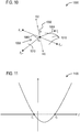
- Fig. 10 illustrates an example determination of a surface normal for a candidate node X 0 1002 of an example mesh 1000 that is connected to an element edge 1004 that fails MEL.
- the surface normal (generally indicated 1008) is the plane intersecting candidate node X 0 1002 that is orientated such that a direction normal to the plane corresponds to the weighted average normal, n 1006, of the ring of elements 1010 surrounding the candidate node, X 0 1002.
- Equation 5 n x 2 + n y 2 + n z 2 t 2 + 2 x 0 + x j n x + y 0 + y j n y + z 0 + z j n z t + x 0 + x j 2 + y 0 + y j 2 + z 0 + z j 2 ⁇ d mel 2
- Fig. 11 shows an example plot 1100 of this quadratic with roots at t 1 and t 2 .
- an algorithm for resolving MEL failures and determining the new position of the candidate node using this first approach may correspond to the following steps:
- the MEL failures which have not been resolved as a result of violating the l max constraint may then become candidates for a second approach carried out by the Node Slider software component 312, in which perturbation of nodes occurs along the shortest edge direction of an edge that is shorter than the desired MEL.
- the at least one processor 102 may be configured (e.g., via the Node Slider software component 312) to move a second subset of the MEL failure nodes to new positions on a respective line that is coincident with a shortest edge connected to the respective node of the second subset being moved in order to cause the shortest edge to have a length that is at least the second predetermined MEL.
- Fig. 12 illustrates edges of a mesh 1200 with quadrilateral elements 1202 (that fail MEL), before (in solid bold lines 1204) and after (in broken lines 1206) nodes 1208, 1210 have been moved in this described manner to remove MEL failures.
- perturbation of the node may be along shortest edge direction to fix MEL failures.
- this approach moves both nodes X 1 1302 and X 2 1304 in contact with an element edge V 1 1306 (which is initially less than d mel ) to new positions along a line 1312 coincident with the edge in opposite directions, to positions X 1 ′ 1308 and X 2 ′ 1310 where the final edge length is equal to d mel .
- X 1 ′ X 1 + ⁇ V ⁇ 1
- X 2 ′ X 2 ⁇ ⁇ V ⁇ 1
- an algorithm for resolving MEL failures and determining the new position of the candidate nodes using this further approach described above may correspond to the following steps:
- the at least one processor 102 may be configured (via the Angle Optimizer software component 406) to determine that at least one included angle 204 of at least one of the quadrilateral elements is either greater than a predetermined maximum angle or less than a predetermined minimum angle.
- the processor may also be configured to determine a node for the determined included angle.
- the processor may be configured to move in the mesh the node for the determined included angle in a direction of a longest edge connected to the node for the determined included angle such that: all of the included angles associated with the moved node in each of the quadrilateral elements that share the moved node have angles that are not greater than the predetermined maximum angle and are not less than the predetermined minimum angle; and all edges connected to the moved node have lengths that are at least the second predetermined edge length.
- Fig. 14 illustrates an example mesh 1400 in which a quadrilateral element 1402 includes an included angle 1404 at node 1406 that is below a predetermined minimum angle.
- Fig. 15 illustrates an example of the resulting modified mesh 1500 after the node 1406 has been moved (rightward along longest connected edge 1408) to result in an included angle 1502 for the quadrilateral element 1402 that is no longer below the predetermined minimum angle.
- the previously described Angle Optimizer software component 406 may carry out angle optimization around a given node in order to minimize the discrepancy between the element included angles which fail the angle limits surrounding a node.
- an optimum configuration may be if each angle was 72°.
- the angles may be evaluated and optimized on a 2D mesh and transformed back to 3D using a Weighted Half-Edge Method flattening algorithm
- the Weighted Half-Edge Method for 2D parameterization of a tessellated 3D face may use a compromise between conformal mapping and triangle altitude preservation techniques to generate 2D domains with highly reduced transformational distortion.
- the meshes are generated in this 2D domain and transformed back to 3D space.
- the objective function f ( x , y ) to be minimized is defined as the average deviation of the included angles surrounding the node from 2 ⁇ ⁇ N according to equation 12.
- the solver employed to minimize the objective function subject to the above constraints may be Powell's Conjugate Direction Method.
- the approach is given an initial estimate which is the x and y values in a unit direction along the longest connected edge from the initial nodal location. This generates an initial set of search vectors.
- the method minimizes the function by a bi-directional search along each search vector, in turn.
- the new position can then be expressed as a linear combination of the search vectors.
- the new displacement vector becomes a new search vector, and is added to the end of the search vector list. Meanwhile, the search vector which contributed most to the new direction, (i.e., the one which was most successful), is deleted from the search vector list.
- the algorithm iterates an arbitrary number of times until no significant improvement is made.
- the approach is that no derivatives of the objective function or constraints are required and the underlying algorithm is simple.
- an algorithm for resolving angle failures may correspond to the following:
- this described Angle Optimizer software component carries out a process whereby the element angle problem and its constraints are posed as an optimization problem and solved as such. This stage focuses on failed angles and with constraints that are validated in such a way that no MEL failures result from the node movement produced by this software component. As a result, the impact on neighboring element angles is minimized.
- the at least one processor 102 may be configured (e.g., via the Warp Smoother software component 408) to determining that a warp of at least one quadrilateral element deviates by more than a predetermined maximum warp.
- the warp of the at least one quadrilateral element may be determined based on deviation of the at least one quadrilateral element from an orthogonal projection of the at least one quadrilateral element on a mean plane that is based on a determined average of normal corner vectors for four corner nodes of the at least one quadrilateral element.
- the at least one processor may be configured to incrementally move in the mesh the corner nodes of the at least one quadrilateral element along the orthogonal projection to positions in which the at least one quadrilateral element has a warp that is at most the predetermined maximum warp.
- Warp Smoother software component may setup a cost function to define the warp metric being pursued.
- a minimization principle may also be worked out to reduce the cost function to an acceptable limit.
- Goal proximity may be managed by defining error norms and their acceptable ranges.
- a mean plane P m 1602 may be defined for any given quad element 1604.
- n average normal vector of the quadrilateral element and r (a,b,c) is the element centroid 1702 (illustrated in the example 1700 of Fig. 17 ) while r 0 (x,y,z) is the origin of the global coordinate system.
- a local coordinate system ( ⁇ ⁇ ⁇ ) may be set up for the mean plane P m ( ⁇ , ⁇ , ⁇ ) .
- Fig. 19 illustrates an example 1900 in which the original quad element Qi (x1, x2, x3, x4) 1604 is shown along with its orthogonal projection Q'i (XI, X2, X3, X4) 1902 on the mean plane P m 1602.
- Minimization happens with respect to the transverse coordinate ⁇ of the mean plane P m .
- the object may be to minimize the global strain energy of non-planarity such that all out-of-plane quads are returned to a planar position.
- the minimization procedure translates to repositioning the corner nodes of each failing quad element along the orthogonal projection or displacement vector v j until warp passes.
- v j X ⁇ j ⁇ x ⁇ j
- a 3-tier termination and/or convergence criteria may be set. For example, the iterative solution may be terminated if:
- alternative embodiments may be configured to determine an amount of warp based on other calculations that estimate angular deviation between a quadrilateral element and the original surfaces from which the mesh was created.
- the at least one processor 102 may be configured (e.g., via the Quad Splitter software component 506) to determine all remaining quadrilateral elements in the mesh that either: have at least one included angle 204 that is either greater than a predetermined maximum angle or less than a predetermined minimum angle; or have a warp 206 that is greater than the predetermined maximum warp.
- the at least one processor 102 may also be configured to split the determined remaining quadrilateral elements into triangles that respectively have no included angles that are greater than the predetermined maximum angle or are less than the predetermined minimum angle.
- the quadrilateral elements may be split along the shortest diagonal unless other constraints exist.
- the Mesh Seamer software component 308 may be re-invoked in a more aggressive fashion. If any element edges remain that fail MEL at this stage these edges are collapsed by the Mesh Seamer software component.
- the at least one processor 102 may be configured (e.g., via the Mesh Seamer) to determine all remaining edges of the plurality of quadrilateral elements, having lengths (202) that are shorter than the second predetermined MEL. The at least one processor may then collapse in the mesh the determined remaining edges to convert each quadrilateral element that included a respective collapsed one of the remaining edges into a respective triangular element.
- the results of these stages (which may include a subset of the described six stages of the mesh quality improvement engine) is the modified surface mesh 116, in which all quadrilaterals in the modified mesh have edge lengths (202) that are at least the second predetermined MEL (e.g., the desired final MEL for the mesh).
- the well-shaped quadrilateral meshes produced by this described process may significantly increase computational efficiency of the downstream finite element solve. This may be desirable for automotive body panel analyses. For example, the efficiency of an automotive crash simulation is highly dependent on the quality of the mesh. In transient dynamic applications such as these, where the solver is time-stepping/explicit, the minimum time step it can cope with is a fraction of the time taken for the speed of sound (i.e., elastic propagation rate through the medium) to cross the smallest element. Consequently, the number of time steps required even for a 2 or 3 second analysis is quite substantial. As a quadrilateral mesh will massively reduce the amount of elements required compared to an equivalent triangular mesh there will be an enormous saving in the time required to converge to a solution.
- the described stages may be invoked in the described operational sequence to address body panel meshes in particular. However, in alternative embodiments, the described stages and sequence can be altered. For example, each of the described software components of the engine may execute independently with several options to control their respective modes of operation.
- the described mesh quality improvement engine may also be flexible via configurable and pluggable software components.
- Example embodiments of the described mesh quality improvement engine may automatically operate on a mesh without manual intervention and inspection of elements in the mesh.
- the example system may thus avoid the need for a user to fix meshes by editing them, which in general is a time consuming, laborious process requiring a high level of skill and expertise.
- Example embodiments may provide a more cost-effective solution that is operative to automatically generated meshes of superior quality than manually edited meshes.
- Fig. 20 various example methodologies are illustrated and described. While the methodologies are described as being a series of acts that are performed in a sequence, it is to be understood that the methodologies may not be limited by the order of the sequence. For instance, some acts may occur in a different order than what is described herein. In addition, an act may occur concurrently with another act. Furthermore, in some instances, not all acts may be required to implement a methodology described herein.
- non-transitory machine usable/readable or computer usable/readable mediums include: ROMs, EPROMs, magnetic tape, hard disk drives, SSDs, flash memory, CDs, DVDs, and Blu-ray disks.
- the computer-executable instructions may include a routine, a sub-routine, programs, applications, modules, libraries, and/or the like. Still further, results of acts of the methodologies may be stored in a computer-readable medium, displayed on a display device, and/or the like.
- the methodology may start at 2002 and may include several acts carried out through operation of at least one processor. These acts may include an act 2004 of determining a first plurality of edges of a plurality of quadrilateral elements that form a surface mesh of a 3D model, which edges have lengths that are shorter than a first predetermined minimum element edge length. Also, these acts may include an act 2006 of collapsing in the mesh the determined first plurality of edges to convert each quadrilateral element that included a respective one of the collapsed first plurality of edges into a respective triangular element.
- the methodology may include an act 2008 of determining a second plurality of edges of the plurality of quadrilateral elements that are shorter than a second predetermined minimum element edge length that are longer than the first predetermined minimum element edge length.
- the acts may include an act 2010 of moving in the mesh a plurality of nodes connected to at least some of the second plurality of edges so that at least some of the second plurality of edges have lengths that are at least the second predetermined minimum element edge length.
- the acts may include an act 2012 of determining all remaining edges of the plurality of quadrilateral elements that are shorter than the second predetermined minimum element edge length.
- the acts may include an act 2014 of collapsing in the mesh the determined remaining edges to convert each quadrilateral element that included a respective collapsed one of the remaining edges into a respective triangular element.
- the methodology may end.
- the methodology may include additional acts associated with adjusting included angles.
- Such acts may include determining through operation of the at least one processor that at least one included angle of at least one of the quadrilateral elements is either greater than a predetermined maximum angle or less than a predetermined minimum angle.
- Such acts may also include determining a node for the determined included angle.
- these acts may include moving in the mesh the node for the determined included angle in a direction of a longest edge connected to the node for the determined included angle such that all of the included angles associated with the moved node in each of the quadrilateral elements that share the moved node have angles that are not greater than the predetermined maximum angle and are not less than the predetermined minimum angle; and all edges connected to the moved node have lengths that are at least the second predetermined edge length.
- the methodology may include additional acts associated with warped elements.
- Such acts may include determining that a warp of at least one quadrilateral element deviates by more than a predetermined maximum warp, wherein the warp of the at least one quadrilateral element is determined based on deviation of the at least one quadrilateral element from an orthogonal projection of the at least one quadrilateral element on a mean plane that is based on a determined average of normal corner vectors for four corner nodes of the at least one quadrilateral element.
- Such acts may also include incrementally moving in the mesh the corner nodes of the at least one quadrilateral element along the orthogonal projection to positions in which the at least one quadrilateral element has a warp that is at most the predetermined maximum warp.
- the methodology may include several acts including determining all remaining quadrilateral elements in the mesh that either: have at least one included angle that is either greater than a predetermined maximum angle or less than a predetermined minimum angle; or have a warp that is greater than the predetermined maximum warp. Further, such acts may include splitting the determined remaining quadrilateral elements into triangles that respectively have no included angles that are greater than the predetermined maximum angle or are less than the predetermined minimum angle.
- act 2010 may include a first approach to moving at least some of the nodes.
- a first approach may include moving a first subset of such nodes (908, 1002) to new positions along determined respective surface normals for each respective node of the first subset, in order to cause each edge connected to each respective node of the first subset to have a length that is: at least the second predetermined minimum element edge length; and not longer than a largest edge in the quadrilateral elements that include the respective edge prior to the respective node of the first subset being moved.
- act 2010 may additionally or alternatively include a second approach to moving at least some of the nodes.
- a second approach may include moving a second subset of the nodes to new positions on a determined respective line that is coincident with a shortest edge connected to the respective node of the second subset being moved in order to cause the shortest edge to have a length that is at least the second predetermined minimum element edge length.
- Example embodiments of the described methodology may also include prior to act 2004 generating the surface mesh from a 3D CAD model of a part, wherein a majority of elements in the surface mesh are quadrilateral elements.
- the methodology may include after act 2014 an act of carrying out a finite element analysis simulation involving the modified surface mesh in order to evaluate how the part changes in response to the simulation.
- acts associated with these methodologies may be carried out by one or more processors.
- processor(s) may be included in one or more data processing systems, for example, that execute software components (including software instructions) operative to cause these acts to be carried out by the one or more processors.
- software components may comprise computer-executable instructions corresponding to a routine, a sub-routine, programs, applications, modules, libraries, a thread of execution, and/or the like.
- software components may be written in and/or produced by software code/environments/languages/frameworks such as machine code, assembly language, Java, JavaScript, Python, C, C#, C++ or any other software tool capable of producing software components and user interfaces configured to carry out the acts and features described herein.
- software code/environments/languages/frameworks such as machine code, assembly language, Java, JavaScript, Python, C, C#, C++ or any other software tool capable of producing software components and user interfaces configured to carry out the acts and features described herein.
- Fig. 21 illustrates a block diagram of a data processing system 2100 (e.g., a computer system) in which an embodiment can be implemented, for example, as a portion of a product system, and/or other system operatively configured by software or otherwise to perform the functions and processes as described herein.
- the data processing system depicted includes at least one processor 2102 (e.g., a CPU) that may be connected to one or more bridges/controllers/buses 2104 (e.g., a north bridge, a south bridge).
- One of the buses 2104 may include one or more I/O buses such as a PCI Express bus.
- Also connected to various buses in the depicted example may include a main memory 2106 (RAM) and a graphics controller 2108.
- RAM main memory 2106
- graphics controller 2108 graphics controller
- the graphics controller 2108 may be connected to one or more display devices 2110. It should also be noted that the processor 2102 may include a CPU cache memory. Further, in some embodiments one or more controllers (e.g., graphics, south bridge) may be integrated with the CPU (on the same chip or die). Examples of CPU architectures include IA-32, x86-64, and ARM processor architectures.
- peripherals connected to one or more buses may include communication controllers 2112 (Ethernet controllers, WiFi controllers, cellular controllers) operative to connect to a local area network (LAN), Wide Area Network (WAN), a cellular network, and/or other wired or wireless networks 2114 or communication equipment.
- communication controllers 2112 Ethernet controllers, WiFi controllers, cellular controllers
- LAN local area network
- WAN Wide Area Network
- cellular network operative to connect to a local area network
- wired or wireless networks 2114 or communication equipment operative to connect to a local area network (LAN), Wide Area Network (WAN), a cellular network, and/or other wired or wireless networks 2114 or communication equipment.
- I/O controllers 2116 such as USB controllers, Bluetooth controllers, and/or dedicated audio controllers (connected to speakers and/or microphones).
- peripherals may be connected to the I/O controller(s) (via various ports and connections) including input devices 2118 (e.g., keyboard, mouse, pointer, touch screen, touch pad, drawing tablet, trackball, buttons, keypad, game controller, gamepad, camera, microphone, scanners, motion sensing devices that capture motion gestures), output devices 2120 (e.g., printers, speakers) or any other type of device that is operative to provide inputs to or receive outputs from the data processing system.
- input devices 2118 e.g., keyboard, mouse, pointer, touch screen, touch pad, drawing tablet, trackball, buttons, keypad, game controller, gamepad, camera, microphone, scanners, motion sensing devices that capture motion gestures
- output devices 2120 e.g., printers, speakers
- the processor 2102 may be integrated into a housing (such as a tablet) that includes a touch screen that serves as both an input and display device.
- a housing such as a tablet
- some input devices such as a laptop
- may include a plurality of different types of input devices e.g., touch screen, touch pad, and keyboard.
- other peripheral hardware 2122 connected to the I/O controllers 2116 may include any type of device, machine, or component that is configured to communicate with a data processing system.
- Additional components connected to various busses may include one or more storage controllers 2124 (e.g., SATA).
- a storage controller may be connected to a storage device 2126 such as one or more storage drives and/or any associated removable media, which can be any suitable non-transitory machine usable or machine readable storage medium. Examples, include nonvolatile devices, volatile devices, read only devices, writable devices, ROMs, EPROMs, magnetic tape storage, floppy disk drives, hard disk drives, solid-state drives (SSDs), flash memory, optical disk drives (CDs, DVDs, Blu-ray), and other known optical, electrical, or magnetic storage devices drives and/or computer media.
- a storage device such as an SSD may be connected directly to an I/O bus 2104 such as a PCI Express bus.
- a data processing system in accordance with an embodiment of the present disclosure may include an operating system 2128, software/firmware 2130, and data stores 2132 (that may be stored on a storage device 2126 and/or the memory 2106).
- Such an operating system may employ a command line interface (CLI) shell and/or a graphical user interface (GUI) shell.
- CLI command line interface
- GUI graphical user interface
- the GUI shell permits multiple display windows to be presented in the graphical user interface simultaneously, with each display window providing an interface to a different application or to a different instance of the same application.
- a cursor or pointer in the graphical user interface may be manipulated by a user through a pointing device such as a mouse or touch screen.
- the position of the cursor/pointer may be changed and/or an event, such as clicking a mouse button or touching a touch screen, may be generated to actuate a desired response.
- operating systems that may be used in a data processing system may include Microsoft Windows, Linux, UNIX, iOS, and Android operating systems.
- data stores include data files, data tables, relational database (e.g., Oracle, Microsoft SQL Server), database servers, or any other structure and/or device that is capable of storing data, which is retrievable by a processor.
- the communication controllers 2112 may be connected to the network 2114 (which may or may not be a part of a data processing system 2100), which can be any local, wide area, remote, private, and/or public data processing system network or combination of networks, as known to those of skill in the art, including the Internet.
- Data processing system 2100 can communicate over the network 2114 with one or more other data processing systems such as a server 2134 (which may in combination correspond to a larger data processing system).
- a larger data processing system may correspond to a plurality of smaller data processing systems implemented as part of a distributed system in which processors associated with several smaller data processing systems may be in communication by way of one or more network connections and may collectively perform tasks described as being performed by a single larger data processing system.
- a data processing system such a system may be implemented across several data processing systems organized in a distributed system in communication with each other via a network.
- controller means any device, system or part thereof that controls at least one operation, whether such a device is implemented in hardware, firmware, software or any combination thereof. It should be noted that the functionality associated with any particular controller may be centralized or distributed, whether locally or remotely.
- the described processor and memory may be included in a controller. Further, a controller may correspond to the described data processing system or any other hardware circuit that is operative to control at least one operation.
- data processing systems may include virtual machines in a virtual machine architecture or cloud environment.
- the processor 2102 and associated components may correspond to the combination of one or more virtual machine processors of a virtual machine operating in one or more physical processors of a physical data processing system.
- virtual machine architectures include VMware ESCi, Microsoft Hyper-V, Xen, and KVM.
- the hardware depicted for the data processing system may vary for particular implementations.
- the data processing system 2100 in this example may correspond to a controller, computer, workstation, server, PC, notebook computer, tablet, mobile phone, and/or any other type of apparatus/system that is operative to process data and carry out functionality and features described herein associated with the operation of a data processing system, computer, processor, software components, and/or a controller discussed herein.
- the depicted example is provided for the purpose of explanation only and is not meant to imply architectural limitations with respect to the present disclosure.
- the processor described herein may correspond to a remote processor located in a data processing system such as a server that is remote from the display and input devices described herein.
- the described display device and input device may be included in a client data processing system (which may have its own processor) that communicates with the server (which includes the remote processor) through a wired or wireless network (which may include the Internet).
- client data processing system may execute a remote desktop application or may correspond to a portal device that carries out a remote desktop protocol with the server in order to send inputs from an input device to the server and receive visual information from the server to display through a display device.
- Such remote desktop protocols include Teradici's PCoIP, Microsoft's RDP, and the RFB protocol.
- client data processing system may execute a web browser or thin client application. Inputs from the user may be transmitted from the web browser or thin client application to be evaluated on the server, rendered by the server, and an image (or series of images) sent back to the client data processing system to be displayed by the web browser or thin client application.
- the remote processor described herein may correspond to a combination of a virtual processor of a virtual machine executing in a physical processor of the server.
- processors described herein may correspond to one or more (or a combination) of a microprocessor, CPU, FPGA, ASIC, or any other integrated circuit (IC) or other type of circuit that is capable of processing data in a data processing system, which may have the form of a controller board, computer, server, mobile phone, and/or any other type of electronic device.
- a microprocessor CPU, FPGA, ASIC, or any other integrated circuit (IC) or other type of circuit that is capable of processing data in a data processing system, which may have the form of a controller board, computer, server, mobile phone, and/or any other type of electronic device.
- phrases "at least one" before an element (e.g., a processor) that is configured to carry out more than one function/process may correspond to one or more elements (e.g., processors) that each carry out the functions/processes and may also correspond to two or more of the elements (e.g., processors) that respectively carry out different ones of the one or more different functions/processes.
- At least one processor that is "configured to" carry out one or more functions or processes is defined herein as the combination of the at least one processor and the particular software/firmware instructions and/or wired circuits that when executed/operated by the at least one processor cause the at least one processor to carry out the one or more functions or processes described or recited herein.
- a processor that is configured to carry out a particular function/process may correspond to the combination of the processor and the software/firmware instructions in which the processor is actively executing at least portions of the software/firmware instructions that are loaded into a volatile memory (e.g., RAM, CPU cache) and that are programmed to cause the processor to carry out the described or recited function/process.
- a volatile memory e.g., RAM, CPU cache
- a processor that is configured to carry out a particular function/process may correspond to the combination of the processor and the software/firmware instructions in which the software/firmware instructions are stored in a non-volatile memory (e.g., flash memory, SSD, hard drive, or other storage device) in operative connection with the processor such that the software/firmware instructions are available to be accessed and executed by the processor to carry out the described function/process (even though none, or only portions of the software/firmware instructions are currently being executed by the processor).
- a non-volatile memory e.g., flash memory, SSD, hard drive, or other storage device
- ком ⁇ онент and “system” are intended to encompass hardware, software, or a combination of hardware and software.
- a system or component may be a process, a process executing on a processor, or a processor.
- a component or system may be localized on a single device or distributed across several devices.
- phrases "associated with” and “associated therewith,” as well as derivatives thereof, may mean to include, be included within, interconnect with, contain, be contained within, connect to or with, couple to or with, be communicable with, cooperate with, interleave, juxtapose, be proximate to, be bound to or with, have, have a property of, or the like.
- first, second, third and so forth may be used herein to refer to various elements, information, functions, or acts, these elements, information, functions, or acts should not be limited by these terms. Rather these numeral adjectives are used to distinguish different elements, information, functions or acts from each other. For example, a first element, information, function, or act could be termed a second element, information, function, or act, and, similarly, a second element, information, function, or act could be termed a first element, information, function, or act, without departing from the scope of the present disclosure.
- adjacent to may mean: that an element is relatively near to but not in contact with a further element; or that the element is in contact with the further portion, unless the context clearly indicates otherwise.
Claims (15)
- Système (100) pour l'amélioration de la qualité d'éléments dans des maillages de surface tridimensionnels (3D) à dominance quadrilatérale comprenant :
au moins un processeur (102) configuré pour :déterminer une première pluralité d'arêtes (608, 810) d'une pluralité d'éléments quadrilatéraux (604, 606, 806) qui forment un maillage de surface (114) d'un modèle 3D, lesquelles arêtes ont des longueurs (202) qui sont plus courtes qu'une première longueur d'arête d'élément minimale prédéterminée ; réduire, dans le maillage, la première pluralité déterminée d'arêtes pour convertir chaque élément quadrilatéral qui comprenait une arête respective de la première pluralité d'arêtes réduite en un élément triangulaire respectif (702, 704, 812, 814) ;après que la première pluralité d'arêtes ont été réduites, déterminer une seconde pluralité d'arêtes (904, 1004, 1204) de la pluralité d'éléments quadrilatéraux (902, 1010, 1202) qui sont plus courtes qu'une seconde longueur d'arête d'élément minimale prédéterminée et qui sont plus longues que la première longueur d'arête d'élément minimale prédéterminée ;
déplacer, dans le maillage, une pluralité de nœuds (908, 1002, 1208, 1210) connectés à au moins certaines arêtes de la seconde pluralité d'arêtes de sorte qu'au moins certaines arêtes de la seconde pluralité d'arêtes aient des longueurs qui sont au moins la seconde longueur d'arête d'élément minimale prédéterminée ;déterminer toutes les arêtes restantes de la pluralité d'éléments quadrilatéraux qui sont plus courtes que la seconde longueur d'arête d'élément minimale prédéterminée ; etréduire, dans le maillage, les arêtes restantes déterminées pour convertir chaque élément quadrilatéral qui comprenait une arête réduite respective des arêtes restantes en un élément triangulaire respectif,
moyennant quoi un maillage de surface modifié (116) est produit, dans lequel tous les quadrilatères dans le maillage modifié ont des longueurs d'arêtes qui sont au moins la seconde longueur d'arête d'élément minimale prédéterminée. - Système selon la revendication 1, dans lequel, avant de déterminer toutes les arêtes restantes de la pluralité d'éléments quadrilatéraux qui sont plus courtes que la seconde longueur d'arête d'élément minimale prédéterminée, l'au moins un processeur est configuré pour :déterminer qu'au moins un angle inclus (204, 1404) d'au moins un des éléments quadrilatéraux (1402) est soit supérieur à un angle maximal prédéterminé, soit inférieur à un angle minimal prédéterminé,déterminer un nœud (1406) pour l'angle inclus déterminé,déplacer, dans le maillage, le nœud pour l'angle inclus déterminé dans la direction de l'arête la plus longue (1408) connectée au nœud pour l'angle inclus déterminé de sorte que :tous les angles inclus associés au nœud déplacé dans chacun des éléments quadrilatéraux qui partagent le nœud déplacé aient des angles qui ne sont pas supérieurs à l'angle maximal prédéterminé et ne sont pas inférieurs à l'angle minimal prédéterminé ; ettoutes les arêtes connectées au nœud déplacé aient des longueurs qui sont au moins la seconde longueur d'arête prédéterminée.
- Système selon l'une quelconque des revendications 1 et 2, dans lequel, avant de déterminer toutes les arêtes restantes de la pluralité d'éléments quadrilatéraux qui sont plus courtes que la seconde longueur d'arête d'élément minimale prédéterminée, l'au moins un processeur est configuré pour :déterminer qu'une distorsion (206) d'au moins un élément quadrilatéral (1604) s'écarte de plus d'une distorsion maximale prédéterminée, dans lequel la distorsion de l'au moins un élément quadrilatéral est déterminée sur la base de l'écart de l'au moins un élément quadrilatéral par rapport à une projection orthogonale (1902) de l'au moins un élément quadrilatéral sur un plan moyen (1602) qui est basé sur une moyenne déterminée de vecteurs de coin normaux (1804, 1806, 1808, 1810) pour quatre nœuds de coin de l'au moins un élément quadrilatéral ;déplacer graduellement dans le maillage les nœuds de coin de l'au moins un élément quadrilatéral le long de la projection orthogonale jusqu'à des positions dans lesquelles l'au moins un élément quadrilatéral présente une distorsion (206) qui est au plus la distorsion maximale prédéterminée.
- Système selon l'une quelconque des revendications 1 à 3, dans lequel, avant de déterminer toutes les arêtes restantes de la pluralité d'éléments quadrilatéraux qui sont plus courtes que la seconde longueur d'arête d'élément minimale prédéterminée, l'au moins un processeur est configuré pour :déterminer tous les éléments quadrilatéraux restants dans le maillage qui soit :ont au moins un angle inclus (204) qui est soit supérieur à un angle maximal prédéterminé, soit inférieur à un angle minimal prédéterminé ; soitprésentent une distorsion (206) qui est supérieure à la distorsion maximale prédéterminée ; etdiviser les éléments quadrilatéraux restants déterminés en triangles qui n'ont respectivement pas d'angles inclus qui sont supérieurs à l'angle maximum prédéterminé ou qui sont inférieurs à l'angle minimal prédéterminé.
- Système selon l'une quelconque des revendications 1 à 4, dans lequel, pour déplacer dans le maillage la pluralité de nœuds connectés à au moins certaines arêtes de la seconde pluralité d'arêtes, l'au moins un processeur est configuré pour déplacer un premier sous-ensemble de ces nœuds (908, 1002) vers de nouvelles positions le long de normales de surface respectives déterminées (1008) pour chaque nœud respectif du premier sous-ensemble, de manière à amener chaque arête connectée à chaque nœud respectif du premier sous-ensemble à avoir une longueur (202) :qui soit au moins la seconde longueur d'arête d'élément minimale prédéterminée ; etqui ne soit pas plus longue que l'arête la plus grande dans les éléments quadrilatéraux qui comprennent l'arête respective avant que le nœud respectif du premier sous-ensemble ne soit déplacé.
- Système selon la revendication 5, dans lequel, pour déplacer dans le maillage la pluralité de nœuds connectés à au moins certaines arêtes de la seconde pluralité d'arêtes (1204, 1306), l'au moins un processeur est configuré pour déplacer un second sous-ensemble des nœuds (1208, 1210, 1302, 1304) vers de nouvelles positions sur une ligne respective déterminée (1312) qui coïncide avec l'arête la plus courte connectée au nœud respectif du second sous-ensemble qui est déplacé de manière à amener l'arête la plus courte à avoir une longueur qui est au moins la seconde longueur d'arête d'élément minimale prédéterminée.
- Système selon l'une quelconque des revendications 1 à 6, dans lequel l'au moins un processeur est configuré pour générer le maillage de surface à partir d'un modèle de CAO 3D (118) d'une pièce, dans lequel une majorité d'éléments dans le maillage de surface sont des éléments quadrilatéraux, où l'au moins un processeur est configuré pour effectuer une simulation par analyse par éléments finis impliquant le maillage de surface modifié pour évaluer comment la pièce change en réponse à la simulation.
- Procédé d'amélioration de la qualité d'éléments dans des maillages de surface tridimensionnels (3D) à dominance quadrilatérale comprenant :
par l'intermédiaire du fonctionnement d'au moins un processeur (102), les étapes suivantes :a) déterminer (2004) une première pluralité d'arêtes (608, 810) d'une pluralité d'éléments quadrilatéraux (604, 606, 806) qui forment un maillage de surface (114) d'un modèle 3D, lesquelles arêtes ont des longueurs (202) qui sont plus courtes qu'une première longueur d'arête d'élément minimale prédéterminée ;b) réduire (2006), dans le maillage, la première pluralité déterminée d'arêtes pour convertir chaque élément quadrilatéral qui comprenait une arête respective de la première pluralité d'arêtes réduites en un élément triangulaire respectif (702, 704, 812, 814) ;c) après l'étape (b), déterminer (2008) une seconde pluralité d'arêtes (904, 1004, 1204) de la pluralité d'éléments quadrilatéraux (902, 1010, 1202) qui sont plus courtes qu'une seconde longueur d'arête d'élément minimale prédéterminée et qui sont plus longues que la première longueur d'arête d'élément minimale prédéterminée ;d) déplacer (2010), dans le maillage, une pluralité de nœuds (908, 1002, 1208, 1210) connectés à au moins certaines arêtes de la seconde pluralité d'arêtes de sorte qu'au moins certaines arêtes de la seconde pluralité d'arêtes aient des longueurs qui sont au moins la seconde longueur d'arête d'élément minimale prédéterminée ;e) déterminer (2012) toutes les arêtes restantes de la pluralité d'éléments quadrilatéraux qui sont plus courtes que la seconde longueur d'arête d'élément minimale prédéterminée ; etf) réduire (2014), dans le maillage, les arêtes restantes déterminées pour convertir chaque élément quadrilatéral qui comprenait une arête réduite respective des arêtes restantes en un élément triangulaire respectif, moyennant quoi un maillage de surface modifié (116) est produit, dans lequel tous les quadrilatères dans le maillage modifié ont des longueurs d'arête qui sont au moins la seconde longueur d'arête d'élément minimale prédéterminée. - Procédé selon la revendication 8, avant l'étape (e), comprenant en outre, par l'intermédiaire du fonctionnement de l'au moins un processeur, les étapes suivantes :déterminer qu'au moins un angle inclus (204, 1404) d'au moins un des éléments quadrilatéraux (1402) est soit supérieur à un angle maximal prédéterminé, soit inférieur à un angle minimal prédéterminé,déterminer un nœud (1406) pour l'angle inclus déterminé,déplacer, dans le maillage, le nœud pour l'angle inclus déterminé dans la direction de l'arête la plus longue (1408) connectée au nœud pour l'angle inclus déterminé de sorte que :tous les angles inclus associés au nœud déplacé dans chacun des éléments quadrilatéraux qui partagent le nœud déplacé aient des angles qui ne sont pas supérieurs à l'angle maximal prédéterminé et ne sont pas inférieurs à l'angle minimal prédéterminé ; ettoutes les arêtes connectées au nœud déplacé aient des longueurs qui sont au moins la seconde longueur d'arête prédéterminée.
- Procédé selon l'une quelconque des revendications 8 et 9, avant l'étape (e), comprenant en outre, par l'intermédiaire du fonctionnement de l'au moins un processeur, les étapes suivantes :déterminer qu'une distorsion (206) d'au moins un élément quadrilatéral (1604) s'écarte de plus d'une distorsion maximale prédéterminée, dans lequel la distorsion de l'au moins un élément quadrilatéral est déterminée sur la base de l'écart de l'au moins un élément quadrilatéral par rapport à une projection orthogonale (1902) de l'au moins un élément quadrilatéral sur un plan moyen (1602) qui est basé sur une moyenne déterminée de vecteurs de coin normaux (1804, 1806, 1808, 1810) pour quatre nœuds de coin de l'au moins un élément quadrilatéral ;déplacer graduellement dans le maillage les nœuds de coin de l'au moins un élément quadrilatéral le long de la projection orthogonale jusqu'à des positions dans lesquelles l'au moins un élément quadrilatéral présente une distorsion (206) qui est au plus la distorsion maximale prédéterminée.
- Procédé selon l'une quelconque des revendications 8 à 10, avant l'étape (e), comprenant en outre, par l'intermédiaire du fonctionnement de l'au moins un processeur, les étapes suivantes :
déterminer tous les éléments quadrilatéraux restants dans le maillage qui soit :ont au moins un angle inclus (204) qui est soit supérieur à un angle maximal prédéterminé, soit inférieur à un angle minimal prédéterminé ; soitprésentent une distorsion (206) qui est supérieure à la distorsion maximale prédéterminée ; etdiviser les éléments quadrilatéraux restants déterminés en triangles qui n'ont respectivement pas d'angles inclus qui sont supérieurs à l'angle maximum prédéterminé ou qui sont inférieurs à l'angle minimal prédéterminé. - Procédé selon l'une quelconque des revendications 8 à 11, dans lequel, dans l'étape (d) le déplacement dans le maillage de la pluralité de nœuds connectés à au moins certaines arêtes de la seconde pluralité d'arêtes comprend de déplacer un premier sous-ensemble de ces nœuds (908, 1002) vers de nouvelles positions le long de normales de surface respectives déterminées (1008) pour chaque nœud respectif du premier sous-ensemble, de manière à amener chaque arête connectée à chaque nœud respectif du premier sous-ensemble à avoir une longueur (202) :qui soit au moins la seconde longueur d'arête d'élément minimale prédéterminée ; etqui ne soit pas plus longue que l'arête la plus grande dans les éléments quadrilatéraux qui comprennent l'arête respective avant que le nœud respectif du premier sous-ensemble ne soit déplacé.
- Procédé selon la revendication 12, dans lequel, dans l'étape (d) le déplacement dans le maillage de la pluralité de nœuds connectés à au moins certaines arêtes de la seconde pluralité d'arêtes (1204, 1306) comprend de déplacer un second sous-ensemble des nœuds (1208, 1210, 1302, 1304) vers de nouvelles positions sur une ligne respective déterminée (1312) qui coïncide avec l'arête la plus courte connectée au nœud respectif du second sous-ensemble qui est déplacé de manière à amener l'arête la plus courte à avoir une longueur qui est au moins la seconde longueur d'arête d'élément minimale prédéterminée.
- Procédé selon l'une quelconque des revendications 8 à 13, comprenant en outre, par l'intermédiaire du fonctionnement de l'au moins un processeur, les étapes suivantes :avant l'étape (a), générer le maillage de surface à partir d'un modèle de CAO 3D (118) d'une pièce, dans lequel une majorité d'éléments dans le maillage de surface sont des éléments quadrilatéraux ; etaprès l'étape (f), effectuer une simulation par analyse par éléments finis impliquant le maillage de surface modifié pour évaluer comment la pièce change en réponse à la simulation.
- Support non transitoire lisible par ordinateur (2126) codé avec des instructions exécutables (106, 2130) qui, lorsqu'elles sont exécutées, amènent au moins un processeur (102, 2102) à exécuter un procédé pour améliorer la qualité d'éléments dans des maillages de surface tridimensionnels (3D) à dominance quadrilatérale selon l'une quelconque des revendications 8 à 14.
Applications Claiming Priority (1)
| Application Number | Priority Date | Filing Date | Title |
|---|---|---|---|
| PCT/US2016/059631 WO2018080527A1 (fr) | 2016-10-31 | 2016-10-31 | Système et procédé d'amélioration de la qualité d'éléments dans des maillages de surface à dominante quadrilatérale en 3d |
Publications (2)
| Publication Number | Publication Date |
|---|---|
| EP3520084A1 EP3520084A1 (fr) | 2019-08-07 |
| EP3520084B1 true EP3520084B1 (fr) | 2020-02-12 |
Family
ID=57321430
Family Applications (1)
| Application Number | Title | Priority Date | Filing Date |
|---|---|---|---|
| EP16795494.0A Active EP3520084B1 (fr) | 2016-10-31 | 2016-10-31 | Système et procédé d'amélioration de la qualité d'éléments dans des maillages de surface à dominante quadrilatérale en 3d |
Country Status (4)
| Country | Link |
|---|---|
| US (1) | US11126766B2 (fr) |
| EP (1) | EP3520084B1 (fr) |
| CN (1) | CN109906472B (fr) |
| WO (1) | WO2018080527A1 (fr) |
Families Citing this family (4)
| Publication number | Priority date | Publication date | Assignee | Title |
|---|---|---|---|---|
| US11783102B2 (en) * | 2019-04-30 | 2023-10-10 | BabySteps Orthopedics Inc. | Predictive modeling platform for serial casting to correct orthopedic deformities |
| CN110750847B (zh) * | 2019-10-29 | 2021-06-15 | 中国科学院过程工程研究所 | 网格切分关系的确定方法、装置、设备和介质 |
| CN114896710B (zh) * | 2022-07-15 | 2022-10-28 | 中国飞机强度研究所 | 用于航空结构冲击分析的接触碰撞分析方法 |
| CN115409950B (zh) * | 2022-10-09 | 2024-02-06 | 卡本(深圳)医疗器械有限公司 | 一种面绘制三角网格的优化方法 |
Family Cites Families (11)
| Publication number | Priority date | Publication date | Assignee | Title |
|---|---|---|---|---|
| US6121973A (en) * | 1998-08-12 | 2000-09-19 | International Business Machines Corporation | Quadrilateral mesh generation method and apparatus |
| FR2788361B1 (fr) * | 1999-01-11 | 2001-05-04 | France Telecom | Procede de simplification d'un maillage source, tenant compte de la courbe locale et de la dynamique geometrique locale, et applications correspondantes |
| US7339584B1 (en) * | 2002-05-29 | 2008-03-04 | Sandia Corporation | Method of generating a surface mesh |
| US6970165B2 (en) * | 2002-12-19 | 2005-11-29 | Ford Motor Company | Method and system for optimizing a finite element mesh |
| US9082220B2 (en) | 2003-08-26 | 2015-07-14 | Siemens Product Lifecycle Management Software Inc. | System, method, and computer program product for smoothing |
| US7443393B2 (en) | 2006-01-19 | 2008-10-28 | International Business Machines Corporation | Method, system, and program product for re-meshing of a three-dimensional input model using progressive implicit approximating levels |
| CN100385464C (zh) * | 2006-03-21 | 2008-04-30 | 中山大学 | 一种基于四边形折叠的三维网格图形简化方法 |
| EP2905744A1 (fr) | 2014-02-05 | 2015-08-12 | Fujitsu Limited | Amélioration de la qualité de maille en ingénierie assistée par ordinateur |
| CN104680573B (zh) | 2015-01-20 | 2018-08-07 | 西安科技大学 | 一种基于三角网格简化的纹理映射方法 |
| CN105006022A (zh) * | 2015-08-11 | 2015-10-28 | 中山大学 | 一种三维几何图形的边折叠简化方法及其装置 |
| US10901118B2 (en) * | 2016-10-28 | 2021-01-26 | Exxonmobil Upstream Research Company | Method and system for enhancing meshes for a subsurface model |
-
2016
- 2016-10-31 WO PCT/US2016/059631 patent/WO2018080527A1/fr unknown
- 2016-10-31 CN CN201680090544.9A patent/CN109906472B/zh active Active
- 2016-10-31 EP EP16795494.0A patent/EP3520084B1/fr active Active
- 2016-10-31 US US16/336,641 patent/US11126766B2/en active Active
Non-Patent Citations (1)
| Title |
|---|
| None * |
Also Published As
| Publication number | Publication date |
|---|---|
| CN109906472A (zh) | 2019-06-18 |
| US20210103685A1 (en) | 2021-04-08 |
| WO2018080527A1 (fr) | 2018-05-03 |
| CN109906472B (zh) | 2020-11-20 |
| EP3520084A1 (fr) | 2019-08-07 |
| US11126766B2 (en) | 2021-09-21 |
Similar Documents
| Publication | Publication Date | Title |
|---|---|---|
| US11230061B2 (en) | System and method for optimizing tool paths based on thermal/structural simulations of a part being produced via a 3D-printer | |
| US11022957B2 (en) | System and method for adaptive domain reduction for thermo-structural simulation of additive manufacturing process | |
| EP3520084B1 (fr) | Système et procédé d'amélioration de la qualité d'éléments dans des maillages de surface à dominante quadrilatérale en 3d | |
| US11003807B2 (en) | Techniques for generating materials to satisfy design criteria | |
| EP3563270B1 (fr) | Système et méthode pour la réalisation la réalisation des gouttes de taille variable pour ameliorer la précision géométrique des couches déposées dans un procédé de fabrication additive | |
| US10956625B2 (en) | Mesh generation system and method | |
| US20120069011A1 (en) | 3d design and modeling system and methods | |
| EP3118817B1 (fr) | Système de post-traitement pour une analyse par éléments finis | |
| US9378327B2 (en) | Canonical forms of layout patterns | |
| US11763524B2 (en) | Layered meshing for additive manufacturing simulations | |
| US9626474B2 (en) | Expanded canonical forms of layout patterns | |
| US10318657B2 (en) | System and method for miter and notch identification for pattern sew line generation | |
| US10780642B2 (en) | System and method for computing surfaces in a multi-layer part | |
| US20150302114A1 (en) | Duplicate pattern of assembly components in cad models | |
| US10345790B2 (en) | Modelling method and system | |
| US20230315965A1 (en) | Method and system for generating a three-dimensional model of a multi-thickness object a computer-aided design environment | |
| US20240152659A1 (en) | Modelling method and system |
Legal Events
| Date | Code | Title | Description |
|---|---|---|---|
| STAA | Information on the status of an ep patent application or granted ep patent |
Free format text: STATUS: UNKNOWN |
|
| STAA | Information on the status of an ep patent application or granted ep patent |
Free format text: STATUS: THE INTERNATIONAL PUBLICATION HAS BEEN MADE |
|
| PUAI | Public reference made under article 153(3) epc to a published international application that has entered the european phase |
Free format text: ORIGINAL CODE: 0009012 |
|
| STAA | Information on the status of an ep patent application or granted ep patent |
Free format text: STATUS: REQUEST FOR EXAMINATION WAS MADE |
|
| 17P | Request for examination filed |
Effective date: 20190430 |
|
| AK | Designated contracting states |
Kind code of ref document: A1 Designated state(s): AL AT BE BG CH CY CZ DE DK EE ES FI FR GB GR HR HU IE IS IT LI LT LU LV MC MK MT NL NO PL PT RO RS SE SI SK SM TR |
|
| AX | Request for extension of the european patent |
Extension state: BA ME |
|
| GRAP | Despatch of communication of intention to grant a patent |
Free format text: ORIGINAL CODE: EPIDOSNIGR1 |
|
| STAA | Information on the status of an ep patent application or granted ep patent |
Free format text: STATUS: GRANT OF PATENT IS INTENDED |
|
| INTG | Intention to grant announced |
Effective date: 20190830 |
|
| GRAS | Grant fee paid |
Free format text: ORIGINAL CODE: EPIDOSNIGR3 |
|
| RAP1 | Party data changed (applicant data changed or rights of an application transferred) |
Owner name: SIEMENS INDUSTRY SOFTWARE INC. |
|
| GRAA | (expected) grant |
Free format text: ORIGINAL CODE: 0009210 |
|
| STAA | Information on the status of an ep patent application or granted ep patent |
Free format text: STATUS: THE PATENT HAS BEEN GRANTED |
|
| DAV | Request for validation of the european patent (deleted) | ||
| DAX | Request for extension of the european patent (deleted) | ||
| AK | Designated contracting states |
Kind code of ref document: B1 Designated state(s): AL AT BE BG CH CY CZ DE DK EE ES FI FR GB GR HR HU IE IS IT LI LT LU LV MC MK MT NL NO PL PT RO RS SE SI SK SM TR |
|
| REG | Reference to a national code |
Ref country code: GB Ref legal event code: FG4D |
|
| REG | Reference to a national code |
Ref country code: CH Ref legal event code: EP |
|
| REG | Reference to a national code |
Ref country code: AT Ref legal event code: REF Ref document number: 1233132 Country of ref document: AT Kind code of ref document: T Effective date: 20200215 |
|
| REG | Reference to a national code |
Ref country code: IE Ref legal event code: FG4D |
|
| REG | Reference to a national code |
Ref country code: DE Ref legal event code: R096 Ref document number: 602016029681 Country of ref document: DE |
|
| PG25 | Lapsed in a contracting state [announced via postgrant information from national office to epo] |
Ref country code: FI Free format text: LAPSE BECAUSE OF FAILURE TO SUBMIT A TRANSLATION OF THE DESCRIPTION OR TO PAY THE FEE WITHIN THE PRESCRIBED TIME-LIMIT Effective date: 20200212 Ref country code: RS Free format text: LAPSE BECAUSE OF FAILURE TO SUBMIT A TRANSLATION OF THE DESCRIPTION OR TO PAY THE FEE WITHIN THE PRESCRIBED TIME-LIMIT Effective date: 20200212 Ref country code: NO Free format text: LAPSE BECAUSE OF FAILURE TO SUBMIT A TRANSLATION OF THE DESCRIPTION OR TO PAY THE FEE WITHIN THE PRESCRIBED TIME-LIMIT Effective date: 20200512 |
|
| REG | Reference to a national code |
Ref country code: LT Ref legal event code: MG4D |
|
| REG | Reference to a national code |
Ref country code: NL Ref legal event code: MP Effective date: 20200212 |
|
| PG25 | Lapsed in a contracting state [announced via postgrant information from national office to epo] |
Ref country code: IS Free format text: LAPSE BECAUSE OF FAILURE TO SUBMIT A TRANSLATION OF THE DESCRIPTION OR TO PAY THE FEE WITHIN THE PRESCRIBED TIME-LIMIT Effective date: 20200612 Ref country code: BG Free format text: LAPSE BECAUSE OF FAILURE TO SUBMIT A TRANSLATION OF THE DESCRIPTION OR TO PAY THE FEE WITHIN THE PRESCRIBED TIME-LIMIT Effective date: 20200512 Ref country code: HR Free format text: LAPSE BECAUSE OF FAILURE TO SUBMIT A TRANSLATION OF THE DESCRIPTION OR TO PAY THE FEE WITHIN THE PRESCRIBED TIME-LIMIT Effective date: 20200212 Ref country code: SE Free format text: LAPSE BECAUSE OF FAILURE TO SUBMIT A TRANSLATION OF THE DESCRIPTION OR TO PAY THE FEE WITHIN THE PRESCRIBED TIME-LIMIT Effective date: 20200212 Ref country code: LV Free format text: LAPSE BECAUSE OF FAILURE TO SUBMIT A TRANSLATION OF THE DESCRIPTION OR TO PAY THE FEE WITHIN THE PRESCRIBED TIME-LIMIT Effective date: 20200212 Ref country code: GR Free format text: LAPSE BECAUSE OF FAILURE TO SUBMIT A TRANSLATION OF THE DESCRIPTION OR TO PAY THE FEE WITHIN THE PRESCRIBED TIME-LIMIT Effective date: 20200513 |
|
| PG25 | Lapsed in a contracting state [announced via postgrant information from national office to epo] |
Ref country code: NL Free format text: LAPSE BECAUSE OF FAILURE TO SUBMIT A TRANSLATION OF THE DESCRIPTION OR TO PAY THE FEE WITHIN THE PRESCRIBED TIME-LIMIT Effective date: 20200212 |
|
| PG25 | Lapsed in a contracting state [announced via postgrant information from national office to epo] |
Ref country code: DK Free format text: LAPSE BECAUSE OF FAILURE TO SUBMIT A TRANSLATION OF THE DESCRIPTION OR TO PAY THE FEE WITHIN THE PRESCRIBED TIME-LIMIT Effective date: 20200212 Ref country code: PT Free format text: LAPSE BECAUSE OF FAILURE TO SUBMIT A TRANSLATION OF THE DESCRIPTION OR TO PAY THE FEE WITHIN THE PRESCRIBED TIME-LIMIT Effective date: 20200705 Ref country code: SK Free format text: LAPSE BECAUSE OF FAILURE TO SUBMIT A TRANSLATION OF THE DESCRIPTION OR TO PAY THE FEE WITHIN THE PRESCRIBED TIME-LIMIT Effective date: 20200212 Ref country code: CZ Free format text: LAPSE BECAUSE OF FAILURE TO SUBMIT A TRANSLATION OF THE DESCRIPTION OR TO PAY THE FEE WITHIN THE PRESCRIBED TIME-LIMIT Effective date: 20200212 Ref country code: SM Free format text: LAPSE BECAUSE OF FAILURE TO SUBMIT A TRANSLATION OF THE DESCRIPTION OR TO PAY THE FEE WITHIN THE PRESCRIBED TIME-LIMIT Effective date: 20200212 Ref country code: ES Free format text: LAPSE BECAUSE OF FAILURE TO SUBMIT A TRANSLATION OF THE DESCRIPTION OR TO PAY THE FEE WITHIN THE PRESCRIBED TIME-LIMIT Effective date: 20200212 Ref country code: EE Free format text: LAPSE BECAUSE OF FAILURE TO SUBMIT A TRANSLATION OF THE DESCRIPTION OR TO PAY THE FEE WITHIN THE PRESCRIBED TIME-LIMIT Effective date: 20200212 Ref country code: LT Free format text: LAPSE BECAUSE OF FAILURE TO SUBMIT A TRANSLATION OF THE DESCRIPTION OR TO PAY THE FEE WITHIN THE PRESCRIBED TIME-LIMIT Effective date: 20200212 Ref country code: RO Free format text: LAPSE BECAUSE OF FAILURE TO SUBMIT A TRANSLATION OF THE DESCRIPTION OR TO PAY THE FEE WITHIN THE PRESCRIBED TIME-LIMIT Effective date: 20200212 |
|
| REG | Reference to a national code |
Ref country code: DE Ref legal event code: R097 Ref document number: 602016029681 Country of ref document: DE |
|
| REG | Reference to a national code |
Ref country code: AT Ref legal event code: MK05 Ref document number: 1233132 Country of ref document: AT Kind code of ref document: T Effective date: 20200212 |
|
| PLBE | No opposition filed within time limit |
Free format text: ORIGINAL CODE: 0009261 |
|
| STAA | Information on the status of an ep patent application or granted ep patent |
Free format text: STATUS: NO OPPOSITION FILED WITHIN TIME LIMIT |
|
| 26N | No opposition filed |
Effective date: 20201113 |
|
| PG25 | Lapsed in a contracting state [announced via postgrant information from national office to epo] |
Ref country code: IT Free format text: LAPSE BECAUSE OF FAILURE TO SUBMIT A TRANSLATION OF THE DESCRIPTION OR TO PAY THE FEE WITHIN THE PRESCRIBED TIME-LIMIT Effective date: 20200212 Ref country code: AT Free format text: LAPSE BECAUSE OF FAILURE TO SUBMIT A TRANSLATION OF THE DESCRIPTION OR TO PAY THE FEE WITHIN THE PRESCRIBED TIME-LIMIT Effective date: 20200212 |
|
| PG25 | Lapsed in a contracting state [announced via postgrant information from national office to epo] |
Ref country code: PL Free format text: LAPSE BECAUSE OF FAILURE TO SUBMIT A TRANSLATION OF THE DESCRIPTION OR TO PAY THE FEE WITHIN THE PRESCRIBED TIME-LIMIT Effective date: 20200212 |
|
| REG | Reference to a national code |
Ref country code: CH Ref legal event code: NV Representative=s name: SIEMENS SCHWEIZ AG, CH |
|
| REG | Reference to a national code |
Ref country code: CH Ref legal event code: PL |
|
| PG25 | Lapsed in a contracting state [announced via postgrant information from national office to epo] |
Ref country code: MC Free format text: LAPSE BECAUSE OF FAILURE TO SUBMIT A TRANSLATION OF THE DESCRIPTION OR TO PAY THE FEE WITHIN THE PRESCRIBED TIME-LIMIT Effective date: 20200212 Ref country code: LU Free format text: LAPSE BECAUSE OF NON-PAYMENT OF DUE FEES Effective date: 20201031 |
|
| REG | Reference to a national code |
Ref country code: BE Ref legal event code: MM Effective date: 20201031 |
|
| PG25 | Lapsed in a contracting state [announced via postgrant information from national office to epo] |
Ref country code: CH Free format text: LAPSE BECAUSE OF NON-PAYMENT OF DUE FEES Effective date: 20201031 Ref country code: BE Free format text: LAPSE BECAUSE OF NON-PAYMENT OF DUE FEES Effective date: 20201031 Ref country code: LI Free format text: LAPSE BECAUSE OF NON-PAYMENT OF DUE FEES Effective date: 20201031 |
|
| PG25 | Lapsed in a contracting state [announced via postgrant information from national office to epo] |
Ref country code: IE Free format text: LAPSE BECAUSE OF NON-PAYMENT OF DUE FEES Effective date: 20201031 |
|
| PG25 | Lapsed in a contracting state [announced via postgrant information from national office to epo] |
Ref country code: TR Free format text: LAPSE BECAUSE OF FAILURE TO SUBMIT A TRANSLATION OF THE DESCRIPTION OR TO PAY THE FEE WITHIN THE PRESCRIBED TIME-LIMIT Effective date: 20200212 Ref country code: MT Free format text: LAPSE BECAUSE OF FAILURE TO SUBMIT A TRANSLATION OF THE DESCRIPTION OR TO PAY THE FEE WITHIN THE PRESCRIBED TIME-LIMIT Effective date: 20200212 Ref country code: CY Free format text: LAPSE BECAUSE OF FAILURE TO SUBMIT A TRANSLATION OF THE DESCRIPTION OR TO PAY THE FEE WITHIN THE PRESCRIBED TIME-LIMIT Effective date: 20200212 |
|
| PG25 | Lapsed in a contracting state [announced via postgrant information from national office to epo] |
Ref country code: MK Free format text: LAPSE BECAUSE OF FAILURE TO SUBMIT A TRANSLATION OF THE DESCRIPTION OR TO PAY THE FEE WITHIN THE PRESCRIBED TIME-LIMIT Effective date: 20200212 Ref country code: AL Free format text: LAPSE BECAUSE OF FAILURE TO SUBMIT A TRANSLATION OF THE DESCRIPTION OR TO PAY THE FEE WITHIN THE PRESCRIBED TIME-LIMIT Effective date: 20200212 |
|
| PG25 | Lapsed in a contracting state [announced via postgrant information from national office to epo] |
Ref country code: SI Free format text: LAPSE BECAUSE OF FAILURE TO SUBMIT A TRANSLATION OF THE DESCRIPTION OR TO PAY THE FEE WITHIN THE PRESCRIBED TIME-LIMIT Effective date: 20200212 |
|
| PGFP | Annual fee paid to national office [announced via postgrant information from national office to epo] |
Ref country code: GB Payment date: 20231106 Year of fee payment: 8 |
|
| PGFP | Annual fee paid to national office [announced via postgrant information from national office to epo] |
Ref country code: FR Payment date: 20231017 Year of fee payment: 8 Ref country code: DE Payment date: 20231214 Year of fee payment: 8 |