EP3519805B1 - Mobilitätsanalysator nach trennung und verfahren zur bestimmung von ionenkollisionsquerschnitten - Google Patents
Mobilitätsanalysator nach trennung und verfahren zur bestimmung von ionenkollisionsquerschnitten Download PDFInfo
- Publication number
- EP3519805B1 EP3519805B1 EP17780860.7A EP17780860A EP3519805B1 EP 3519805 B1 EP3519805 B1 EP 3519805B1 EP 17780860 A EP17780860 A EP 17780860A EP 3519805 B1 EP3519805 B1 EP 3519805B1
- Authority
- EP
- European Patent Office
- Prior art keywords
- ions
- drift tube
- separation device
- mobility
- group
- Prior art date
- Legal status (The legal status is an assumption and is not a legal conclusion. Google has not performed a legal analysis and makes no representation as to the accuracy of the status listed.)
- Active
Links
Images
Classifications
-
- G—PHYSICS
- G01—MEASURING; TESTING
- G01N—INVESTIGATING OR ANALYSING MATERIALS BY DETERMINING THEIR CHEMICAL OR PHYSICAL PROPERTIES
- G01N27/00—Investigating or analysing materials by the use of electric, electrochemical, or magnetic means
- G01N27/62—Investigating or analysing materials by the use of electric, electrochemical, or magnetic means by investigating the ionisation of gases, e.g. aerosols; by investigating electric discharges, e.g. emission of cathode
- G01N27/622—Ion mobility spectrometry
-
- H—ELECTRICITY
- H01—ELECTRIC ELEMENTS
- H01J—ELECTRIC DISCHARGE TUBES OR DISCHARGE LAMPS
- H01J49/00—Particle spectrometers or separator tubes
- H01J49/0027—Methods for using particle spectrometers
-
- H—ELECTRICITY
- H01—ELECTRIC ELEMENTS
- H01J—ELECTRIC DISCHARGE TUBES OR DISCHARGE LAMPS
- H01J49/00—Particle spectrometers or separator tubes
- H01J49/0027—Methods for using particle spectrometers
- H01J49/0031—Step by step routines describing the use of the apparatus
-
- H—ELECTRICITY
- H01—ELECTRIC ELEMENTS
- H01J—ELECTRIC DISCHARGE TUBES OR DISCHARGE LAMPS
- H01J49/00—Particle spectrometers or separator tubes
- H01J49/004—Combinations of spectrometers, tandem spectrometers, e.g. MS/MS, MSn
-
- H—ELECTRICITY
- H01—ELECTRIC ELEMENTS
- H01J—ELECTRIC DISCHARGE TUBES OR DISCHARGE LAMPS
- H01J49/00—Particle spectrometers or separator tubes
- H01J49/26—Mass spectrometers or separator tubes
- H01J49/34—Dynamic spectrometers
- H01J49/42—Stability-of-path spectrometers, e.g. monopole, quadrupole, multipole, farvitrons
- H01J49/4205—Device types
- H01J49/422—Two-dimensional RF ion traps
- H01J49/4225—Multipole linear ion traps, e.g. quadrupoles, hexapoles
-
- H—ELECTRICITY
- H01—ELECTRIC ELEMENTS
- H01J—ELECTRIC DISCHARGE TUBES OR DISCHARGE LAMPS
- H01J49/00—Particle spectrometers or separator tubes
- H01J49/26—Mass spectrometers or separator tubes
- H01J49/34—Dynamic spectrometers
- H01J49/42—Stability-of-path spectrometers, e.g. monopole, quadrupole, multipole, farvitrons
Definitions
- the present invention relates generally to mass spectrometers and methods of mass spectrometry, and in particular to ion mobility spectrometry and methods of separating ions according to ion mobility.
- a key attribute of ion mobility separation is the capability to determine collision cross section ("CCS") values.
- Standard mobility separation devices involve the application of a constant or static DC voltage across the length of a drift tube, and this allows determination of collision cross-section values from first principles.
- T-Wave travelling wave
- collision cross-section values are not attainable from first principles, but may be derived or estimated through the use of appropriate mobility calibration compounds.
- DMS differential mobility separation
- GB 2530835 discloses measuring ion mobility in a MS-IMS tandem device.
- GB 2529924 discloses determining the collision cross-section of ions in an ion mobility separator through calibration.
- the technology disclosed herein is aimed at providing an alternative and improved (e.g., quicker and deterministic) method of measuring collision cross sections of ions that are emerging from a high resolution separation device.
- the drift tube can be provided to quickly determine the collision cross section of ions emerging from the first separation device before those ions are onwardly transmitted to other parts of a spectrometer.
- the method as described herein also does not require the use of calibrants to measure collision cross section.
- the drift tube may operate at a fast cycle time relative to the first separation device.
- Cycle time (or cycle of separation) may be defined as the time taken for the slowest ion in a given population, group or cluster of ions to travel through, and exit, a separation device if all of the ions in the population, group or cluster of ions are introduced into the separation device at substantially the same time.
- the cycle time of the first separation device may be at least 10, 20, 30, 40, 50 or 100 times greater than the cycle time of the drift tube.
- the drift tube may be configured to separate successive groups of ions emerging from the first separation device in a continuous manner and/or at the same time.
- One or more groups of ions may be pulsed into the drift tube (e.g., from the first separation device) whilst one or more preceding groups of ions, or at least some ions in one or more preceding groups of ions are still present (e.g., still being separated) in the drift tube.
- the drift tube may be configured to separate at least 2, 3, 4, 5 or 10 groups of ions at the same time.
- the drift tube there would be a reduced mobility range within the drift tube at any one time (due to pre-separation in the first separation device) and so 'overpulsing' of groups of ions into (i.e., multiple groups of ions being separated within) the drift tube is possible. In other words, more than one group of ions would be present in the drift tube.
- the pulsing period i.e., the period of time between pulsing each group into the drift tube
- each group of ions may be sampled at multiple points across the range of values of the first physico-chemical property within that group of ions.
- the physico-chemical property is ion mobility
- multiple values of collision cross section may be determined for ions in each group of ions.
- the step of determining the mobility of ions in each group of ions may comprise one or more of (i) applying a DC voltage gradient along the length of the drift tube, (ii) varying the DC voltage gradient across a range of different values, (iii) measuring an arrival time distribution of ion species travelling through the drift tube, and (iv) plotting a graph of drift time against voltage drop across the drift tube, for example using the above equation.
- the mobility and/or collision cross section of ions may be determined directly from the line of best fit of this graph.
- the mobility and/or collision cross section may be determined from first principles, and without the use of calibrants, for example.
- the method may comprise applying a constant DC voltage to the plurality of electrodes to urge ions along the entire length of the drift tube.
- the first physico-chemical property comprises ion mobility.
- Each group of ions may correspond to a mobility peak emerging from the first separation device.
- Each mobility peak may be sampled at multiple points such that multiple collision cross section values may be determined across each mobility peak.
- Each group of ions may correspond to a range of said first physico-chemcial property.
- One or more voltages may be applied to the drift tube such that a voltage gradient (e.g., a voltage drop), e.g., a DC voltage gradient exists or is present along the length of the drift tube that is less than 50 V, 30 V, 20 V or 10 V.
- a voltage gradient e.g., a voltage drop
- a DC voltage gradient exists or is present along the length of the drift tube that is less than 50 V, 30 V, 20 V or 10 V.
- the drift tube and/or the electrodes of the drift tube may have a length that is less than 10 cm, 5 cm, 4 cm, 3 cm, 2 cm or 1 cm.
- the length of the drift tube may be at least 2, 3, 4, 5, 10, 20, 50 or 100 times shorter than the length of the first separation device.
- the drift tube may be arranged and adapted to separate ions according to the same physico-chemical property, e.g., ion mobility, as the first separation device.
- the drift tube may follow immediately from the first separation device.
- the determination of the collision cross section of the ions in each group of ions using the determined mobility may represent a nested acquisition of collision cross section within the timescale of the high resolution separator.
- the apparatus may form part of a spectrometer, for example an ion mobility spectrometer.
- a rapid, low resolution, linear field separator in the form of a drift tube
- a first separation device e.g., a travelling wave ion mobility separator
- the spectrometer may comprise an ion source selected from the group consisting of: (i) an Electrospray ionisation (“ESI”) ion source; (ii) an Atmospheric Pressure Photo lonisation (“APPI”) ion source; (iii) an Atmospheric Pressure Chemical Ionisation (“APCI”) ion source; (iv) a Matrix Assisted Laser Desorption Ionisation (“MALDI”) ion source; (v) a Laser Desorption Ionisation (“LDI”) ion source; (vi) an Atmospheric Pressure Ionisation (“API”) ion source; (vii) a Desorption lonisation on Silicon (“DIOS”) ion source; (viii) an Electron Impact (“EI”) ion source; (ix) a Chemical Ionisation (“Cl”) ion source; (x) a Field Ionisation (“Fl”) ion source; (xi) a Field Desorption (“FD”) ion source; (
- the spectrometer may comprise one or more continuous or pulsed ion sources.
- the spectrometer may comprise one or more ion guides.
- the spectrometer may comprise one or more ion mobility separation devices and/or one or more Field Asymmetric Ion Mobility Spectrometer devices.
- the spectrometer may comprise one or more ion traps or one or more ion trapping regions.
- the spectrometer may comprise one or more collision, fragmentation or reaction cells selected from the group consisting of: (i) a Collisional Induced Dissociation (“CID”) fragmentation device; (ii) a Surface Induced Dissociation (“SID”) fragmentation device; (iii) an Electron Transfer Dissociation (“ETD”) fragmentation device; (iv) an Electron Capture Dissociation (“ECD”) fragmentation device; (v) an Electron Collision or Impact Dissociation fragmentation device; (vi) a Photo Induced Dissociation (“PID”) fragmentation device; (vii) a Laser Induced Dissociation fragmentation device; (viii) an infrared radiation induced dissociation device; (ix) an ultraviolet radiation induced dissociation device; (x) a nozzle-skimmer interface fragmentation device; (xi) an in-source fragmentation device; (xii) an in-source Collision Induced Dissociation fragmentation device; (xiii) a thermal or temperature source
- the spectrometer may comprise a mass analyser selected from the group consisting of: (i) a quadrupole mass analyser; (ii) a 2D or linear quadrupole mass analyser; (iii) a Paul or 3D quadrupole mass analyser; (iv) a Penning trap mass analyser; (v) an ion trap mass analyser; (vi) a magnetic sector mass analyser; (vii) Ion Cyclotron Resonance ("ICR”) mass analyser; (viii) a Fourier Transform Ion Cyclotron Resonance (“FTICR”) mass analyser; (ix) an electrostatic mass analyser arranged to generate an electrostatic field having a quadro-logarithmic potential distribution; (x) a Fourier Transform electrostatic mass analyser; (xi) a Fourier Transform mass analyser; (xii) a Time of Flight mass analyser; (xiii) an orthogonal acceleration Time of Flight mass analyser; and (xiv) a linear acceleration
- the spectrometer may comprise one or more energy analysers or electrostatic energy analysers.
- the spectrometer may comprise one or more ion detectors.
- the spectrometer may comprise one or more mass filters selected from the group consisting of: (i) a quadrupole mass filter; (ii) a 2D or linear quadrupole ion trap; (iii) a Paul or 3D quadrupole ion trap; (iv) a Penning ion trap; (v) an ion trap; (vi) a magnetic sector mass filter; (vii) a Time of Flight mass filter; and (viii) a Wien filter.
- mass filters selected from the group consisting of: (i) a quadrupole mass filter; (ii) a 2D or linear quadrupole ion trap; (iii) a Paul or 3D quadrupole ion trap; (iv) a Penning ion trap; (v) an ion trap; (vi) a magnetic sector mass filter; (vii) a Time of Flight mass filter; and (viii) a Wien filter.
- the spectrometer may comprise a device or ion gate for pulsing ions; and/or a device for converting a substantially continuous ion beam into a pulsed ion beam.
- the spectrometer may comprise a C-trap and a mass analyser comprising an outer barrel-like electrode and a coaxial inner spindle-like electrode that form an electrostatic field with a quadro-logarithmic potential distribution, wherein in a first mode of operation ions are transmitted to the C-trap and are then injected into the mass analyser and wherein in a second mode of operation ions are transmitted to the C-trap and then to a collision cell or Electron Transfer Dissociation device wherein at least some ions are fragmented into fragment ions, and wherein the fragment ions are then transmitted to the C-trap before being injected into the mass analyser.
- the spectrometer may comprise a stacked ring ion guide comprising a plurality of electrodes each having an aperture through which ions are transmitted in use and wherein the spacing of the electrodes increases along the length of the ion path, and wherein the apertures in the electrodes in an upstream section of the ion guide have a first diameter and wherein the apertures in the electrodes in a downstream section of the ion guide have a second diameter which is smaller than the first diameter, and wherein opposite phases of an AC or RF voltage are applied, in use, to successive electrodes.
- the spectrometer may comprise a device arranged and adapted to supply an AC or RF voltage to the electrodes.
- the AC or RF voltage optionally has an amplitude selected from the group consisting of: (i) about ⁇ 50 V peak to peak; (ii) about 50-100 V peak to peak; (iii) about 100-150 V peak to peak; (iv) about 150-200 V peak to peak; (v) about 200-250 V peak to peak; (vi) about 250-300 V peak to peak; (vii) about 300-350 V peak to peak; (viii) about 350-400 V peak to peak; (ix) about 400-450 V peak to peak; (x) about 450-500 V peak to peak; and (xi) > about 500 V peak to peak.
- the AC or RF voltage may have a frequency selected from the group consisting of: (i) ⁇ about 100 kHz; (ii) about 100-200 kHz; (iii) about 200-300 kHz; (iv) about 300-400 kHz; (v) about 400-500 kHz; (vi) about 0.5-1.0 MHz; (vii) about 1.0-1.5 MHz; (viii) about 1.5-2.0 MHz; (ix) about 2.0-2.5 MHz; (x) about 2.5-3.0 MHz; (xi) about 3.0-3.5 MHz; (xii) about 3.5-4.0 MHz; (xiii) about 4.0-4.5 MHz; (xiv) about 4.5-5.0 MHz; (xv) about 5.0-5.5 MHz; (xvi) about 5.5-6.0 MHz; (xvii) about 6.0-6.5 MHz; (xviii) about 6.5-7.0 MHz; (xix) about 7.0-7.5 MHz; (xx) about 7.5-8.0 MHz
- the spectrometer may comprise a chromatography or other separation device upstream of an ion source.
- the chromatography separation device may comprise a liquid chromatography or gas chromatography device.
- the separation device may comprise: (i) a Capillary Electrophoresis (“CE”) separation device; (ii) a Capillary Electrochromatography (“CEC”) separation device; (iii) a substantially rigid ceramic-based multilayer microfluidic substrate (“ceramic tile”) separation device; or (iv) a supercritical fluid chromatography separation device.
- the ion guide may be maintained at a pressure selected from the group consisting of: (i) ⁇ about 0.0001 mbar; (ii) about 0.0001-0.001 mbar; (iii) about 0.001-0.01 mbar; (iv) about 0.01-0.1 mbar; (v) about 0.1-1 mbar; (vi) about 1-10 mbar; (vii) about 10-100 mbar; (viii) about 100-1000 mbar; and (ix) > about 1000 mbar.
- Analyte ions may be subjected to Electron Transfer Dissociation ("ETD") fragmentation in an Electron Transfer Dissociation fragmentation device.
- ETD Electron Transfer Dissociation
- Analyte ions may be caused to interact with ETD reagent ions within an ion guide or fragmentation device.
- analyte ions are fragmented or are induced to dissociate and form product or fragment ions upon interacting with reagent ions; and/or (b) electrons are transferred from one or more reagent anions or negatively charged ions to one or more multiply charged analyte cations or positively charged ions whereupon at least some of the multiply charged analyte cations or positively charged ions are induced to dissociate and form product or fragment ions; and/or (c) analyte ions are fragmented or are induced to dissociate and form product or fragment ions upon interacting with neutral reagent gas molecules or atoms or a non-ionic reagent gas; and/or (d) electrons are transferred from one or more neutral, non-ionic or uncharged basic gases or vapours to one or more multiply charged analyte cations or positively charged ions whereupon at least some of the multiply charged analy
- the multiply charged analyte cations or positively charged ions may comprise peptides, polypeptides, proteins or biomolecules.
- the reagent anions or negatively charged ions are derived from a polyaromatic hydrocarbon or a substituted polyaromatic hydrocarbon; and/or (b) the reagent anions or negatively charged ions are derived from the group consisting of: (i) anthracene; (ii) 9,10 diphenyl-anthracene; (iii) naphthalene; (iv) fluorine; (v) phenanthrene; (vi) pyrene; (vii) fluoranthene; (viii) chrysene; (ix) triphenylene; (x) perylene; (xi) acridine; (xii) 2,2' dipyridyl; (xiii) 2,2' biquinoline; (xiv) 9-anthracenecarbonitrile; (xv) dibenzothiophene; (xvi) 1,10'-phenanthroline;
- the process of Electron Transfer Dissociation fragmentation may comprise interacting analyte ions with reagent ions, wherein the reagent ions comprise dicyanobenzene, 4-nitrotoluene or azulene.
- a chromatography detector may be provided, wherein the chromatography detector comprises either: a destructive chromatography detector optionally selected from the group consisting of (i) a Flame Ionization Detector (FID); (ii) an aerosol-based detector or Nano Quantity Analyte Detector (NQAD); (iii) a Flame Photometric Detector (FPD); (iv) an Atomic-Emission Detector (AED); (v) a Nitrogen Phosphorus Detector (NPD); and (vi) an Evaporative Light Scattering Detector (ELSD); or a non-destructive chromatography detector optionally selected from the group consisting of: (i) a fixed or variable wavelength UV detector; (ii) a Thermal Conductivity Detector (TCD); (iii) a fluorescence detector; (iv) an Electron Capture Detector (ECD); (v) a conductivity monitor; (vi) a Photoionization Detector (PID); (vii)
- the spectrometer may be operated in various modes of operation including a mass spectrometry ("MS”) mode of operation; a tandem mass spectrometry (“MS/MS”) mode of operation; a mode of operation in which parent or precursor ions are alternatively fragmented or reacted so as to produce fragment or product ions, and not fragmented or reacted or fragmented or reacted to a lesser degree; a Multiple Reaction Monitoring (“MRM”) mode of operation; a Data Dependent Analysis (“DDA”) mode of operation; a Data Independent Analysis (“DIA”) mode of operation a Quantification mode of operation or an Ion Mobility Spectrometry (“IMS”) mode of operation.
- MRM Multiple Reaction Monitoring
- DDA Data Dependent Analysis
- DIA Data Independent Analysis
- IMS Ion Mobility Spectrometry
- the present disclosure involves using a drift tube to sample multiple groups of ions emerging from a high resolution ion mobility separator, for example a travelling wave ion mobility separator, to allow determination of collision cross section values for the various ion species that are separated in the travelling wave ion mobility separator.
- a high resolution ion mobility separator for example a travelling wave ion mobility separator
- This obviates the need to use a calibration standard to determine the collision cross section, which is necessary, for example, if a travelling wave ion mobility separator is used to determine the ion mobility.
- the drift tube may be configured to separate multiple groups of ions emerging from a first separation device at the same time.
- One or more subsequent groups of ions may be pulsed into a drift tube (e.g., from the first separation device) whilst one or more preceding groups of ions, or at least some ions in one or more preceding groups of ions are still present (e.g., still being separated) in the drift tube.
- the drift tube may be configured to separate at least 2, 3, 4, 5 or 10 groups of ions at the same time. In these embodiments there would be a reduced mobility range within the drift tube at any one time and so 'overpulsing' of groups of ions into (i.e., multiple groups of ions being separated within) the drift tube is possible.
- the pulsing period i.e., the period of time between pulsing each group into the drift tube
- the pulsing period would optionally be of the same timescale as the frequency in which the groups emerge from the first separation device.
- the drift tube may operate at a fast cycle time relative to the first separation device.
- Cycle time (or cycle of separation) may be defined as the time taken for the slowest ion in a given population, group or cluster of ions to travel through, and exit a separation device if all of the ions in the population, group or cluster of ions are introduced into the separation device at substantially the same time.
- the cycle time of the first separation device may be at least 10, 20, 30, 40, 50 or 100 times greater than the cycle time of the drift tube.
- the low resolution separator may sample the groups of ions emerging from the high resolution separator in terms of collision cross section.
- a mobility peak emerging from the high resolution separator may be sampled many times for collision cross section values.
- the drift tube involves the use of one or more electrodes, along which a driving DC voltage gradient is applied.
- the DC voltage may be static and decrease in strength along the length of the drift tube, which causes ions have a high mobility to pass through the drift tube faster than ions having a low mobility.
- the collision cross section of an ion species may be determined by varying the DC voltage gradient across a range of different values, measuring the arrival time distribution of the ion species, and plotting a graph of drift time against voltage drop across the drift tube.
- the ion mobility and collision cross section may be determined directly from the line of best fit of this graph.
- Typical drift tube ion mobility separators can be relatively long and require a large voltage drop across the length of the drift tube to provide high resolution (the resolution of a DC drift tube is proportional to the square root of the voltage drop across the the drift tube).
- the collision cross section of the ions travelling through the drift tube may be determined from the mobility of those ions.
- a travelling wave ion mobility separator may involve the use of a plurality of electrodes, each having an aperture through which ions travel in use, such that a different voltage can be applied to each electrode.
- Other travelling wave ion mobility separators may be used, in which a plurality of axial groups of electrodes are provided rather than a single electrode having an aperture.
- each axial grouping of electrodes may be provided in the form of a ring divided into segments, such that different potentials may be applied to the different segments.
- transient DC voltages or potentials are applied to the plurality of electrodes in order to urge ions along said separation device.
- the DC voltages or potentials may be swept, translated or sequentially applied along at least a portion of the axial length of the travelling wave device with a first velocity, which causes ions to be separated according to their ion mobility.
- the collision cross section of ions emerging from a travelling wave device cannot be determined directly (i.e., from first principles) as described above in relation to the drift tube. This is because there is a non-uniform and time/position varying electric field, due to the application of transient DC voltages or potentials, and so the relationship between mobility and drift time is more complex than given in Equation 1.
- the drift time of a plurality of calibrant ion species must be measured.
- a plot of the collision cross section (adjusted for charge state and reduced mass) of the calibrants (from a known library) against their drift time can be produced and a calibration curve determined, and from this the analyte collision cross sections may be determined using their measured drift times.
- the technology of the present disclosure may obviate the need to use calibration compounds in order to determine the collision cross section of ions emerging from a travelling wave ion mobility separator, or other separation device. This is through the provision of a low resolution DC drift tube following the travelling wave ion mobility separator.
- the drift tube of the present disclosure can operate at a short cycle time relative to the high resolution separation device, such that multiple cycles can be completed by the drift tube in a single cycle of separation of the high resolution separation device.
- the drift tube of the present disclosure can be a short, low voltage, low resolution device.
- the drift tube may operate with a short enough cycle time and/or repetition rate, and/or fast enough separation time, so that the mobility peaks arriving from the upstream separator can be multiply sampled.
- a plurality of collision cross section values may be determined for each mobility peak emerging from the separation device (e.g., a travelling wave ion mobility separator). For example, at least 2, 3, 4, 5, 10 or 20 collision cross section values may be determined for each mobility peak emerging from the separation device.
- the technology of the present disclosure may allow nested acquisitions within the timescale of the high resolution separator. It is a consequence of this short timescale that the drift tube may be physically short. This has a knock-on effect in that the voltage drop across the drift tube can be small, e.g., to stay below a low field limit for accurate CCS measurements, which can have the further knock-on effect that the resolution may be relatively low.
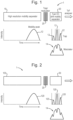
- Fig. 1 shows an apparatus 1 including a first separation device 10 that is arranged and configured to separate ions according to their ion mobility.
- the first separation device 10 is a travelling wave ion mobility separator (e.g., as described above), and/or may comprise a plurality of electrodes, each having an aperture through which ions travel in use, such that a different voltage can be applied to each electrode.
- the travelling wave ion mobility separator 10 may comprise a plurality of axial groups of electrodes.
- the first separation device 10 is arranged and configured to apply one or more transient DC voltages or potentials to at least some of the electrodes in order to urge ions along said separation device.
- the one or more transient DC voltages or potentials may be swept, translated or sequentially applied along at least a portion of the axial length of the first separation device 10 with a first velocity, so as to cause ions to be separated according to their ion mobility.
- the first separation device 10 may be operated at a relatively high resolution, for example in order to cause ions travelling through the first separation device 10 to separate into distinct groups (e.g., mobility peaks 12) as shown schematically in Fig. 1 .
- mobility peaks 12 e.g., mobility peaks 12
- the apparatus 1 may further comprise an ion trap 20, which may be arranged and configured to keep the mobility peaks 12 emerging from the first separation device 10 separate.
- the ion trap 20 may be replaced by a modulation device, which could be arranged and configured to modulate the mobility peaks 12 emerging from the first separation device 10 so that they form a modulated group of ions 14.
- the modulation of the mobility peaks 12 may be recorded and can be used to demodulate the peaks at a later stage, or otherwise extract information from the modulated group of ions 14. For example, the intensity of the ion signal for each group of ions 12 could be perturbed, and the transit time (drift time) for each perturbation could be recorded, and then optionally used for demodulation.
- the perturbation could be imposed through application of a transient DC potential to a lens element in the ion trap 20, which could be arranged and configured to momentarily attenuate or block an ion beam passing through the ion trap 20, which could lead to partial or full extinction of the signal.
- the time between the applied perturbation and the recorded arrival of the perturbed signal at the detection system may then be used to determine mobility values.
- the perturbation can be such that no ions are lost, e.g., if the transient DC potential is applied in a region where RF confinement is present, or (less favourably) such that ions are lost, for example due to a lack of RF ion confinement or through use of a shutter grid to cut the signal.
- the ion trap 20 may be replaced with a transport device that inherently modulates the ion beam, such as a travelling wave ion guide which may be arranged and configured to keep groups of ions emerging from the first separation device 10 in a separate potential well that is transported along the length of the transport device.
- a transport device that inherently modulates the ion beam, such as a travelling wave ion guide which may be arranged and configured to keep groups of ions emerging from the first separation device 10 in a separate potential well that is transported along the length of the transport device.
- a drift tube 30 is provided downstream of the first separation device 10 and ion trap 20 (if provided).
- the drift tube 30 comprises a plurality of electrodes, and a static, driving DC voltage gradient may be applied to the plurality of electrodes. As discussed above, the DC voltage will decrease in strength along the length of the drift tube 30. In this manner, ions having a high mobility may pass through the drift tube 30 faster than ions having a low mobility.
- the drift tube 30 may operate at a relatively low resolution (compared to the first separation device 10) due to the fast cycle time relative to the first separation device 10. In various embodiments the drift tube 30 may be shorter. For example, the axial length of the drift tube 30 may be less than 50%, 40%, 30%, 20% or 10% of the axial length of the first separation device 10.
- the separation time of the drift tube 30 may be lower than that of the first separation device 10.
- the separation time of the drift tube 30 may be less than 50%, 40%, 30%, 20% or 10% of the separation time of the first separation device 10.
- the repetition rate of the drift tube 30 may be higher than that of the first separation device 10.
- the repetition rate of the drift tube 30 may be at least 3, 4, 5, 10 or 20 times greater than the repetition rate of the first separation device 10.
- ions entering the first separation device 10 are separated according to a first physico-chemical property, specifically according to ion mobility.
- the ions travelling through the first separation device 10 may be separated into groups of ions, and each group may be passed to the ion trap 20 and optionally kept separate therein (or modulated as described above).
- Each group of ions may comprise ions having a value or range of values of the first physico-chemical property.
- each group of ions may comprise ions having an ion mobility within a first range, and/or may correspond to a mobility peak 12 as shown in Fig. 1 .
- the groups of ions may then be sampled using the drift tube 30. To do this the groups of ions may be transferred into the drift tube 30.
- the groups of ions could be transferred sequentially, where the groups of ions are kept separate in the upstream ion trap 20, or the groups of ions could be modulated and transferred as part of a modulated group of ions 14 as discussed above.
- each group of ions may be sampled at multiple points across the range of values of the first physico-chemical property.
- the drift tube 30 may produce multiple sample points (and hence values for the collision cross section) across each mobility peak 12 exiting the first separation device 10. These values can be used to provide multiple measurements for averaging the mobility peak 12, and/or be used to give an indication of the purity of the mobility peak 12. For example, the variance in the collision cross section values across each mobility peak could be determined.
- the drift tube 30 may be located within the same gas chamber as the first separation device 10.
- the first separation device 10 comprises a travelling wave ion mobility separator
- this can be advantageous since the drift gas can be the same for both devices.
- it may be advantageous to have the drift tube 30 as a separate gas chamber to the first separation device 10, for example if different gases were required for each device.
- different separating media e.g., drift gases
- drift gases may be used in first separation device 10 and the drift tube 30.
- the first separation device 10 and the drift tube 30 may form part of the same ion optical assembly.
- the first separation device 10 and the drift tube 30 may be located within the same chamber (e.g., gas chamber).
- both devices comprise stacked ring electrodes (i.e., electrodes having apertures through which ions travel in use)
- the devices may form part of the same stack of electrodes.
- the groups of ions that are passed through the drift tube 30 can be onwardly transmitted to a time of flight mass analyser.
- the collision cross section of ions within each group may be sampled as described above and determined directly, i.e., without the use of a calibrant.
- the broadest aspects of this disclosure can also provide benefits over the use of a high resolution drift tube (which would typically be used as a stand-alone device).
- a separation device in particular a travelling wave ion mobility separator
- upstream of the drift tube leads to improved flexibility and control over the separation of ions prior to their introduction into the drift tube.
- high resolution drift tubes typically require a large voltage drop, which is not required when using the low resolution drift tube described herein (e.g., drift tube 30 as described above and in relation to Fig. 1 ).
- travelling wave devices and drift tubes operating under similar conditions will operate on similar timescales and have similar resolutions, and it would not be possible to use the drift tube to provide multiple CCS measurements across a mobility peak.
- a 1 m long travelling wave separation device with a temporal resolution of 40, and a mobility peak at 40 ms drift time may have a FWHM peak width of about 1 ms.
- a 1 m long drift tube operating at 10 V/cm (1000 V drop across cell) may have a temporal resolution of about 60 for a singly charged ion at 298 K.
- the drift time for an ion having a collision cross section of 230 ⁇ 2 , with a drift gas (e.g., N 2 ) having a pressure of 2 mb might be around 20-25 ms.
- the long drift tube could not be directly nested with the travelling wave separation device.
- the length of the drift tube can be reduced in accordance with the disclosure.
- the drift tube could be about 2 cm long, for example. Maintaining the 10 V/cm field would require only a 20 V drop across the length of the shorter drift tube, giving a temporal resolution of about 8.
- Parameters other than length may be altered in order to reduce the resolution of the drift tube, in accordance with the disclosure.
- the drift gas pressure and/or electric field could be varied to alter the drift time.
- limitations may apply in ensuring that the drift tube separation remains within the low field limit, e.g., to ensure that there is no significant heating of the ions.
- ions may be caused to fragment in the first separation device 10 and/or the drift tube 30.
- the groups of ions emerging from the first separation device 10 may alternatively be caused to undergo fragmentation between the first separation device 10 and the drift tube 30.
- the first separation device is a quadrupole mass analyser 100 arranged and adapted to separate ions according to their mass to charge ratio and not to separate ions according to ion mobility.
- a first population of ions may be separated according to mass to charge ratio in a quadrupole mass filter 100, and groups of ions 120 emerging from the quadrupole mass filter 100 may be separated in the drift tube 30, wherein the drift tube 30 operates at a fast cycle time relative to the transmission cycle of the quadrupole mass filter 100, such that the mobility and collision cross section of ions within each group of ions 120 can be determined can be sampled, each group of ions 120 having a particular range of mass to charge ratios.
- the remaining objects of this example, such as the trap/modulator 20 and drift tube 30 may be the same as described above in respect of Fig. 1 .
- the first separation device 10 may be provided in the form of one or more separation devices that may be arranged and configured to separate ions according to one or more physico-chemical properties and ion mobility.
- ion mobility and/or collision cross section may be determined using the drift tube and the determined ion mobility and/or collision cross section may be used to calculate or measure the one or more physico-chemical properties.
- a separation device in the form of a travelling wave separation device wherein ions may be driven in pseudo-potential wells may separate ions according to both mass to charge ratio and ion mobility.
- the mobility of ions eluting from such a separation device may be determined by measuring their drift time through the drift tube 30, and then the mass to charge ratio of these ions may be determined using the determined mobility.
- the first separation device 10 may be cyclic, for example a cyclic ion mobility separation device.
- the highest resolution of the cyclic device can be achieved when ions have undergone multiple passes of the device. In these situations, it is likely that ions of significantly different mobilities may overlap as higher mobility ions catch lower mobility ions as they cycle around the device.
- the drift tube 30 may be located downstream of the cyclic device, so that the overlapping ions of different mobilities can be separated in the drift tube 30. At the same time the collision cross section of ions may be determined in the manner discussed above.
Landscapes
- Chemical & Material Sciences (AREA)
- Analytical Chemistry (AREA)
- Physics & Mathematics (AREA)
- Spectroscopy & Molecular Physics (AREA)
- Chemical Kinetics & Catalysis (AREA)
- Electrochemistry (AREA)
- Health & Medical Sciences (AREA)
- Life Sciences & Earth Sciences (AREA)
- Biochemistry (AREA)
- General Health & Medical Sciences (AREA)
- General Physics & Mathematics (AREA)
- Immunology (AREA)
- Pathology (AREA)
- Other Investigation Or Analysis Of Materials By Electrical Means (AREA)
- Electron Tubes For Measurement (AREA)
Claims (7)
- Verfahren, umfassend:Trennen einer ersten lonenpopulation gemäß einer ersten physikalisch-chemischen Eigenschaft in einer ersten Trennvorrichtung (10); undTrennen einer oder mehrerer Ionengruppen, die aus der ersten Trennvorrichtung (10) austreten, in einer Driftröhre (30) und Abtasten jeder lonengruppe unter Verwendung der Driftröhre (30), um den Kollisionsquerschnitt von Ionen in jeder lonengruppe zu bestimmen, wobei jede lonengruppe einem Bereich der ersten physikalisch-chemischen Eigenschaft entspricht;wobei die Driftröhre (30) so konfiguriert ist, dass mehrere Ionengruppen in der ersten lonenpopulation durch die Driftröhre (30) in einem einzigen Trennzyklus der ersten Trennvorrichtung (10) abgetastet werden können, und der Schritt der Abtastung jeder lonengruppe Folgendes umfasst:Bestimmen der Mobilität der Ionen in jeder lonengruppe durch Messen ihrer Driftzeit durch die Driftröhre (30); undBestimmen des Kollisionsquerschnitts der Ionen in jeder lonengruppe unter Verwendung der bestimmten Mobilität;wobei die erste physikalisch-chemische Eigenschaft die lonenmobilität ist;wobei die Driftröhre (30) eine Vielzahl von Elektroden umfasst, und das Verfahren weiter Anlegen eines konstanten Gleichspannungsgradienten an die Vielzahl von Elektroden umfasst, um Ionen entlang der Driftröhre (30) zu treiben;wobei die erste Trennvorrichtung (10) eine Vielzahl von Elektroden umfasst und das Verfahren weiter Anlegen einer oder mehrerer transienter Gleichspannungen oder - potentiale an mindestens einige der Elektroden der ersten Trennvorrichtung (10) umfasst, um Ionen entlang der Trennvorrichtung zu treiben; undwobei die eine oder mehreren transienten Gleichspannungen oder -potentiale entlang mindestens eines Abschnitts der axialen Länge der ersten Trennvorrichtung (10) mit einer ersten Geschwindigkeit gewobbelt, verschoben oder sequentiell angelegt werden, um eine Trennung der Ionen gemäß ihrer lonenmobilität zu bewirken.
- Verfahren nach Anspruch 1, wobei die Driftröhre (30) zum gleichzeitigen Trennen mehrerer aus der ersten Trennvorrichtung (10) austretender Ionengruppen konfiguriert ist.
- Verfahren nach einem vorstehenden Anspruch, wobei jede lonengruppe an mehreren Punkten über den Wertebereich der ersten physikalisch-chemischen Eigenschaft innerhalb dieser lonengruppe abgetastet wird.
- Verfahren nach einem vorstehenden Anspruch, wobei jede lonengruppe einer Mobilitätsspitze entspricht, die aus der ersten Trennvorrichtung (10) austritt, und jede Mobilitätsspitze an mehreren Punkten abgetastet wird, sodass mehrere Kollisionsquerschnittswerte über jede Mobilitätsspitze bestimmt werden.
- Verfahren nach einem vorstehenden Anspruch, wobei ein Spannungsabfall über der Driftröhre (30) weniger als 50 V, 30 V, 20 V oder 10 V beträgt.
- Verfahren nach einem vorstehenden Anspruch, wobei eine Länge der Driftröhre (30) weniger als 10 cm, 5 cm, 4 cm, 3 cm, 2 cm oder 1 cm beträgt.
- Einrichtung, umfassend:eine erste Trennvorrichtung (10), die zum Trennen einer ersten lonenpopulation gemäß einer ersten physikalisch-chemischen Eigenschaft angeordnet und konfiguriert ist;eine Driftröhre (30), die zum Trennen einer oder mehrerer Ionengruppen, die aus der ersten Trennvorrichtung (10) austreten, angeordnet und konfiguriert ist, und so, dass bei der Verwendung mehrere Ionengruppen in der ersten lonenpopulation durch die Driftröhre (30) in einem einzigen Trennzyklus der ersten Trennvorrichtung (10) abgetastet werden können, wobei jede lonengruppe einem Bereich der ersten physikalisch-chemischen Eigenschaft entspricht; undein Steuersystem, das zum Abtasten jeder lonengruppe angeordnet und konfiguriert ist, um den Kollisionsquerschnitt der Ionen in jeder lonengruppe zu bestimmen durch:(i) Bestimmen der Mobilität der Ionen in jeder lonengruppe durch Messen ihrer Driftzeit durch die Driftröhre (30); und(ii) Bestimmen des Kollisionsquerschnitts der Ionen in jeder lonengruppe unter Verwendung der bestimmten Mobilität;wobei die erste physikalisch-chemische Eigenschaft die lonenmobilität ist;wobei die Driftröhre (30) eine Vielzahl von Elektroden umfasst, und die Einrichtung zum Anlegen eines konstanten Gleichspannungsgradienten an die Vielzahl von Elektroden konfiguriert ist, um Ionen entlang der Driftröhre (30) zu treiben;wobei die erste Trennvorrichtung (10) eine Vielzahl von Elektroden umfasst und die Einrichtung zum Anlegen einer oder mehrerer transienter Gleichspannungen oder - potentiale an mindestens einige der Elektroden der ersten Trennvorrichtung (10) konfiguriert ist, um Ionen entlang der Trennvorrichtung zu treiben; undwobei die Einrichtung für die eine oder mehreren transienten Gleichspannungen oder -potentiale konfiguriert ist, um entlang mindestens eines Abschnitts der axialen Länge der ersten Trennvorrichtung (10) mit einer ersten Geschwindigkeit gewobbelt, verschoben oder sequentiell angelegt zu werden, um eine Trennung der Ionen gemäß ihrer lonenmobilität zu bewirken.
Applications Claiming Priority (2)
| Application Number | Priority Date | Filing Date | Title |
|---|---|---|---|
| GB1616395.8A GB2562690B (en) | 2016-09-27 | 2016-09-27 | Post-separation mobility analyser |
| PCT/GB2017/052881 WO2018060690A1 (en) | 2016-09-27 | 2017-09-27 | Post-separation mobility analyser and method for determining ion collision cross-sections |
Publications (2)
| Publication Number | Publication Date |
|---|---|
| EP3519805A1 EP3519805A1 (de) | 2019-08-07 |
| EP3519805B1 true EP3519805B1 (de) | 2024-11-20 |
Family
ID=57539925
Family Applications (1)
| Application Number | Title | Priority Date | Filing Date |
|---|---|---|---|
| EP17780860.7A Active EP3519805B1 (de) | 2016-09-27 | 2017-09-27 | Mobilitätsanalysator nach trennung und verfahren zur bestimmung von ionenkollisionsquerschnitten |
Country Status (6)
| Country | Link |
|---|---|
| US (1) | US11402350B2 (de) |
| EP (1) | EP3519805B1 (de) |
| JP (1) | JP6768938B2 (de) |
| CN (1) | CN109791125B (de) |
| GB (1) | GB2562690B (de) |
| WO (1) | WO2018060690A1 (de) |
Families Citing this family (4)
| Publication number | Priority date | Publication date | Assignee | Title |
|---|---|---|---|---|
| CN110455907B (zh) * | 2019-07-04 | 2022-04-19 | 昆山禾信质谱技术有限公司 | 基于飞行时间质量分析器的串联质谱数据分析方法 |
| GB202001249D0 (en) * | 2020-01-29 | 2020-03-11 | Waters Technologies Ireland Ltd | Techniques for sample analysis using product ion collision-cross section information |
| GB202011470D0 (en) * | 2020-07-24 | 2020-09-09 | Micromass Ltd | ION mobility separation |
| GB2629671B (en) | 2022-03-08 | 2025-02-26 | Thermo Fisher Scient Bremen Gmbh | Disambiguation of cyclic ion analyser spectra |
Family Cites Families (22)
| Publication number | Priority date | Publication date | Assignee | Title |
|---|---|---|---|---|
| US6791078B2 (en) * | 2002-06-27 | 2004-09-14 | Micromass Uk Limited | Mass spectrometer |
| GB0408751D0 (en) * | 2004-04-20 | 2004-05-26 | Micromass Ltd | Mass spectrometer |
| GB0420408D0 (en) | 2004-09-14 | 2004-10-20 | Micromass Ltd | Mass spectrometer |
| GB0524972D0 (en) * | 2005-12-07 | 2006-01-18 | Micromass Ltd | Mass spectrometer |
| US9523657B2 (en) * | 2006-02-14 | 2016-12-20 | Excellims Corporation | Practical ion mobility spectrometer apparatus and methods for chemical and/or biological detection |
| CN101093211B (zh) | 2006-06-21 | 2010-05-12 | 中国科学院电子学研究所 | 用于离子迁移率谱仪漂移管的瞬态漂移电场方法 |
| DE102007017055B4 (de) * | 2007-04-11 | 2011-06-22 | Bruker Daltonik GmbH, 28359 | Messung der Mobilität massenselektierter Ionen |
| GB0817115D0 (en) * | 2008-09-18 | 2008-10-29 | Micromass Ltd | Mass spectrometer |
| GB201021360D0 (en) * | 2010-12-16 | 2011-01-26 | Thermo Fisher Scient Bremen Gmbh | Apparatus and methods for ion mobility spectrometry |
| GB201122251D0 (en) * | 2011-12-23 | 2012-02-01 | Micromass Ltd | Multi-pass ion mobility separation device |
| GB201205009D0 (en) | 2012-03-22 | 2012-05-09 | Micromass Ltd | Multi-dimensional survey scans for improved data dependent acquisitions (DDA) |
| CN103364480B (zh) | 2013-07-11 | 2015-07-15 | 中国船舶重工集团公司第七一八研究所 | 离子迁移谱爆炸物探测系统 |
| US9482642B2 (en) * | 2014-01-31 | 2016-11-01 | Agilent Technologies, Inc. | Fast method for measuring collision cross section of ions utilizing ion mobility spectrometry |
| DE112015001169T5 (de) * | 2014-03-10 | 2016-12-22 | Micromass Uk Limited | Bestätigung unter Verwendung einer Mehrzahl von Kollisionsquerschnitts-("CCS")-Messungen |
| WO2015173577A1 (en) | 2014-05-14 | 2015-11-19 | Micromass Uk Limited | De-convolution of overlapping ion mobility spectrometer or separator data |
| GB201408554D0 (en) * | 2014-05-14 | 2014-06-25 | Micromass Ltd | De-convolution of overlapping ion mobility spectrometer or separator data |
| EP3146322B1 (de) * | 2014-05-22 | 2024-07-10 | W. Henry Benner | Instrumente zur messung der ionengrössenverteilung und -konzentration |
| GB201409578D0 (en) * | 2014-05-30 | 2014-07-16 | Micromass Ltd | Combined tandem mass spectrometry and ion mobility mass spectrometry |
| GB201410052D0 (en) * | 2014-06-06 | 2014-07-16 | Micromass Ltd | Mobility selective attenuation |
| US10304674B2 (en) | 2014-08-19 | 2019-05-28 | Micromass Uk Limited | Time of flight mass spectrometer |
| GB201508197D0 (en) * | 2015-05-14 | 2015-06-24 | Micromass Ltd | Trap fill time dynamic range enhancement |
| US11237154B2 (en) * | 2015-05-29 | 2022-02-01 | Waters Technologies Corporation | Metabolic pathway and metabolite identification |
-
2016
- 2016-09-27 GB GB1616395.8A patent/GB2562690B/en active Active
-
2017
- 2017-09-27 WO PCT/GB2017/052881 patent/WO2018060690A1/en not_active Ceased
- 2017-09-27 EP EP17780860.7A patent/EP3519805B1/de active Active
- 2017-09-27 US US16/337,361 patent/US11402350B2/en active Active
- 2017-09-27 JP JP2019516525A patent/JP6768938B2/ja active Active
- 2017-09-27 CN CN201780057386.1A patent/CN109791125B/zh active Active
Non-Patent Citations (1)
| Title |
|---|
| KNAPMAN T W ET AL: "Considerations in experimental and theoretical collision cross-section measurements of small molecules using travelling wave ion mobility spectrometry-mass spectrometry", INTERNATIONAL JOURNAL OF MASS SPECTROMETRY, ELSEVIER SCIENCE PUBLISHERS , AMSTERDAM, NL, vol. 298, no. 1-3, 1 December 2010 (2010-12-01), pages 17 - 23, XP027492678, ISSN: 1387-3806, [retrieved on 20091004], DOI: 10.1016/J.IJMS.2009.09.011 * |
Also Published As
| Publication number | Publication date |
|---|---|
| WO2018060690A1 (en) | 2018-04-05 |
| CN109791125B (zh) | 2022-01-28 |
| US20210293752A1 (en) | 2021-09-23 |
| GB2562690A (en) | 2018-11-28 |
| US11402350B2 (en) | 2022-08-02 |
| CN109791125A (zh) | 2019-05-21 |
| EP3519805A1 (de) | 2019-08-07 |
| GB2562690B (en) | 2022-11-02 |
| GB201616395D0 (en) | 2016-11-09 |
| JP6768938B2 (ja) | 2020-10-14 |
| JP2019529922A (ja) | 2019-10-17 |
Similar Documents
| Publication | Publication Date | Title |
|---|---|---|
| US9576781B2 (en) | Intelligent dynamic range enhancement | |
| CN110892503B (zh) | 使用时变电场的迁移率和质量测量 | |
| US11488815B2 (en) | Trap fill time dynamic range enhancment | |
| EP3047508B1 (de) | Massenspektrometer | |
| US9881781B2 (en) | Optimized multiple reaction monitoring or single ion recording method | |
| EP3519805B1 (de) | Mobilitätsanalysator nach trennung und verfahren zur bestimmung von ionenkollisionsquerschnitten | |
| US10304674B2 (en) | Time of flight mass spectrometer | |
| EP3073259B1 (de) | Absorptionsmodus-ft-ims | |
| US10041907B2 (en) | Accurate mobility chromatograms | |
| US9899200B2 (en) | Multi-dimensional ion separation | |
| US10068761B2 (en) | Fast modulation with downstream homogenisation | |
| US11733206B2 (en) | Multiplexing method for separators | |
| GB2533835A (en) | Fast modulation with downstream homogenisation | |
| GB2520153A (en) | Mass spectrometer | |
| GB2539871A (en) | A method of mass spectrometry | |
| GB2518275A (en) | Intelligent dynamic range enhancement | |
| GB2534252A (en) | Time of flight mass spectrometer |
Legal Events
| Date | Code | Title | Description |
|---|---|---|---|
| STAA | Information on the status of an ep patent application or granted ep patent |
Free format text: STATUS: UNKNOWN |
|
| STAA | Information on the status of an ep patent application or granted ep patent |
Free format text: STATUS: THE INTERNATIONAL PUBLICATION HAS BEEN MADE |
|
| PUAI | Public reference made under article 153(3) epc to a published international application that has entered the european phase |
Free format text: ORIGINAL CODE: 0009012 |
|
| STAA | Information on the status of an ep patent application or granted ep patent |
Free format text: STATUS: REQUEST FOR EXAMINATION WAS MADE |
|
| 17P | Request for examination filed |
Effective date: 20190411 |
|
| AK | Designated contracting states |
Kind code of ref document: A1 Designated state(s): AL AT BE BG CH CY CZ DE DK EE ES FI FR GB GR HR HU IE IS IT LI LT LU LV MC MK MT NL NO PL PT RO RS SE SI SK SM TR |
|
| AX | Request for extension of the european patent |
Extension state: BA ME |
|
| DAV | Request for validation of the european patent (deleted) | ||
| DAX | Request for extension of the european patent (deleted) | ||
| STAA | Information on the status of an ep patent application or granted ep patent |
Free format text: STATUS: EXAMINATION IS IN PROGRESS |
|
| 17Q | First examination report despatched |
Effective date: 20211103 |
|
| GRAP | Despatch of communication of intention to grant a patent |
Free format text: ORIGINAL CODE: EPIDOSNIGR1 |
|
| STAA | Information on the status of an ep patent application or granted ep patent |
Free format text: STATUS: GRANT OF PATENT IS INTENDED |
|
| INTG | Intention to grant announced |
Effective date: 20240318 |
|
| GRAJ | Information related to disapproval of communication of intention to grant by the applicant or resumption of examination proceedings by the epo deleted |
Free format text: ORIGINAL CODE: EPIDOSDIGR1 |
|
| STAA | Information on the status of an ep patent application or granted ep patent |
Free format text: STATUS: EXAMINATION IS IN PROGRESS |
|
| GRAP | Despatch of communication of intention to grant a patent |
Free format text: ORIGINAL CODE: EPIDOSNIGR1 |
|
| STAA | Information on the status of an ep patent application or granted ep patent |
Free format text: STATUS: GRANT OF PATENT IS INTENDED |
|
| INTC | Intention to grant announced (deleted) | ||
| INTG | Intention to grant announced |
Effective date: 20240709 |
|
| GRAS | Grant fee paid |
Free format text: ORIGINAL CODE: EPIDOSNIGR3 |
|
| GRAA | (expected) grant |
Free format text: ORIGINAL CODE: 0009210 |
|
| STAA | Information on the status of an ep patent application or granted ep patent |
Free format text: STATUS: THE PATENT HAS BEEN GRANTED |
|
| P01 | Opt-out of the competence of the unified patent court (upc) registered |
Free format text: CASE NUMBER: APP_55509/2024 Effective date: 20241009 |
|
| AK | Designated contracting states |
Kind code of ref document: B1 Designated state(s): AL AT BE BG CH CY CZ DE DK EE ES FI FR GB GR HR HU IE IS IT LI LT LU LV MC MK MT NL NO PL PT RO RS SE SI SK SM TR |
|
| REG | Reference to a national code |
Ref country code: GB Ref legal event code: FG4D |
|
| REG | Reference to a national code |
Ref country code: CH Ref legal event code: EP |
|
| REG | Reference to a national code |
Ref country code: DE Ref legal event code: R096 Ref document number: 602017086257 Country of ref document: DE |
|
| REG | Reference to a national code |
Ref country code: IE Ref legal event code: FG4D |
|
| REG | Reference to a national code |
Ref country code: LT Ref legal event code: MG9D |
|
| REG | Reference to a national code |
Ref country code: NL Ref legal event code: MP Effective date: 20241120 |
|
| PG25 | Lapsed in a contracting state [announced via postgrant information from national office to epo] |
Ref country code: HR Free format text: LAPSE BECAUSE OF FAILURE TO SUBMIT A TRANSLATION OF THE DESCRIPTION OR TO PAY THE FEE WITHIN THE PRESCRIBED TIME-LIMIT Effective date: 20241120 Ref country code: PT Free format text: LAPSE BECAUSE OF FAILURE TO SUBMIT A TRANSLATION OF THE DESCRIPTION OR TO PAY THE FEE WITHIN THE PRESCRIBED TIME-LIMIT Effective date: 20250320 Ref country code: IS Free format text: LAPSE BECAUSE OF FAILURE TO SUBMIT A TRANSLATION OF THE DESCRIPTION OR TO PAY THE FEE WITHIN THE PRESCRIBED TIME-LIMIT Effective date: 20250320 |
|
| PG25 | Lapsed in a contracting state [announced via postgrant information from national office to epo] |
Ref country code: FI Free format text: LAPSE BECAUSE OF FAILURE TO SUBMIT A TRANSLATION OF THE DESCRIPTION OR TO PAY THE FEE WITHIN THE PRESCRIBED TIME-LIMIT Effective date: 20241120 Ref country code: NL Free format text: LAPSE BECAUSE OF FAILURE TO SUBMIT A TRANSLATION OF THE DESCRIPTION OR TO PAY THE FEE WITHIN THE PRESCRIBED TIME-LIMIT Effective date: 20241120 |
|
| REG | Reference to a national code |
Ref country code: AT Ref legal event code: MK05 Ref document number: 1743994 Country of ref document: AT Kind code of ref document: T Effective date: 20241120 |
|
| PG25 | Lapsed in a contracting state [announced via postgrant information from national office to epo] |
Ref country code: BG Free format text: LAPSE BECAUSE OF FAILURE TO SUBMIT A TRANSLATION OF THE DESCRIPTION OR TO PAY THE FEE WITHIN THE PRESCRIBED TIME-LIMIT Effective date: 20241120 |
|
| PG25 | Lapsed in a contracting state [announced via postgrant information from national office to epo] |
Ref country code: ES Free format text: LAPSE BECAUSE OF FAILURE TO SUBMIT A TRANSLATION OF THE DESCRIPTION OR TO PAY THE FEE WITHIN THE PRESCRIBED TIME-LIMIT Effective date: 20241120 |
|
| PG25 | Lapsed in a contracting state [announced via postgrant information from national office to epo] |
Ref country code: NO Free format text: LAPSE BECAUSE OF FAILURE TO SUBMIT A TRANSLATION OF THE DESCRIPTION OR TO PAY THE FEE WITHIN THE PRESCRIBED TIME-LIMIT Effective date: 20250220 |
|
| PG25 | Lapsed in a contracting state [announced via postgrant information from national office to epo] |
Ref country code: AT Free format text: LAPSE BECAUSE OF FAILURE TO SUBMIT A TRANSLATION OF THE DESCRIPTION OR TO PAY THE FEE WITHIN THE PRESCRIBED TIME-LIMIT Effective date: 20241120 Ref country code: LV Free format text: LAPSE BECAUSE OF FAILURE TO SUBMIT A TRANSLATION OF THE DESCRIPTION OR TO PAY THE FEE WITHIN THE PRESCRIBED TIME-LIMIT Effective date: 20241120 Ref country code: GR Free format text: LAPSE BECAUSE OF FAILURE TO SUBMIT A TRANSLATION OF THE DESCRIPTION OR TO PAY THE FEE WITHIN THE PRESCRIBED TIME-LIMIT Effective date: 20250221 |
|
| PG25 | Lapsed in a contracting state [announced via postgrant information from national office to epo] |
Ref country code: PL Free format text: LAPSE BECAUSE OF FAILURE TO SUBMIT A TRANSLATION OF THE DESCRIPTION OR TO PAY THE FEE WITHIN THE PRESCRIBED TIME-LIMIT Effective date: 20241120 |
|
| PG25 | Lapsed in a contracting state [announced via postgrant information from national office to epo] |
Ref country code: RS Free format text: LAPSE BECAUSE OF FAILURE TO SUBMIT A TRANSLATION OF THE DESCRIPTION OR TO PAY THE FEE WITHIN THE PRESCRIBED TIME-LIMIT Effective date: 20250220 |
|
| PG25 | Lapsed in a contracting state [announced via postgrant information from national office to epo] |
Ref country code: SM Free format text: LAPSE BECAUSE OF FAILURE TO SUBMIT A TRANSLATION OF THE DESCRIPTION OR TO PAY THE FEE WITHIN THE PRESCRIBED TIME-LIMIT Effective date: 20241120 |
|
| PG25 | Lapsed in a contracting state [announced via postgrant information from national office to epo] |
Ref country code: DK Free format text: LAPSE BECAUSE OF FAILURE TO SUBMIT A TRANSLATION OF THE DESCRIPTION OR TO PAY THE FEE WITHIN THE PRESCRIBED TIME-LIMIT Effective date: 20241120 |
|
| PG25 | Lapsed in a contracting state [announced via postgrant information from national office to epo] |
Ref country code: EE Free format text: LAPSE BECAUSE OF FAILURE TO SUBMIT A TRANSLATION OF THE DESCRIPTION OR TO PAY THE FEE WITHIN THE PRESCRIBED TIME-LIMIT Effective date: 20241120 |
|
| PG25 | Lapsed in a contracting state [announced via postgrant information from national office to epo] |
Ref country code: RO Free format text: LAPSE BECAUSE OF FAILURE TO SUBMIT A TRANSLATION OF THE DESCRIPTION OR TO PAY THE FEE WITHIN THE PRESCRIBED TIME-LIMIT Effective date: 20241120 |
|
| PG25 | Lapsed in a contracting state [announced via postgrant information from national office to epo] |
Ref country code: SK Free format text: LAPSE BECAUSE OF FAILURE TO SUBMIT A TRANSLATION OF THE DESCRIPTION OR TO PAY THE FEE WITHIN THE PRESCRIBED TIME-LIMIT Effective date: 20241120 |
|
| PG25 | Lapsed in a contracting state [announced via postgrant information from national office to epo] |
Ref country code: CZ Free format text: LAPSE BECAUSE OF FAILURE TO SUBMIT A TRANSLATION OF THE DESCRIPTION OR TO PAY THE FEE WITHIN THE PRESCRIBED TIME-LIMIT Effective date: 20241120 |
|
| PG25 | Lapsed in a contracting state [announced via postgrant information from national office to epo] |
Ref country code: IT Free format text: LAPSE BECAUSE OF FAILURE TO SUBMIT A TRANSLATION OF THE DESCRIPTION OR TO PAY THE FEE WITHIN THE PRESCRIBED TIME-LIMIT Effective date: 20241120 |
|
| REG | Reference to a national code |
Ref country code: DE Ref legal event code: R097 Ref document number: 602017086257 Country of ref document: DE |
|
| PG25 | Lapsed in a contracting state [announced via postgrant information from national office to epo] |
Ref country code: SE Free format text: LAPSE BECAUSE OF FAILURE TO SUBMIT A TRANSLATION OF THE DESCRIPTION OR TO PAY THE FEE WITHIN THE PRESCRIBED TIME-LIMIT Effective date: 20241120 |
|
| PLBE | No opposition filed within time limit |
Free format text: ORIGINAL CODE: 0009261 |
|
| STAA | Information on the status of an ep patent application or granted ep patent |
Free format text: STATUS: NO OPPOSITION FILED WITHIN TIME LIMIT |
|
| PGFP | Annual fee paid to national office [announced via postgrant information from national office to epo] |
Ref country code: DE Payment date: 20250820 Year of fee payment: 9 |
|
| PGFP | Annual fee paid to national office [announced via postgrant information from national office to epo] |
Ref country code: GB Payment date: 20250822 Year of fee payment: 9 |
|
| 26N | No opposition filed |
Effective date: 20250821 |