EP3073259B1 - Absorptionsmodus-ft-ims - Google Patents
Absorptionsmodus-ft-ims Download PDFInfo
- Publication number
- EP3073259B1 EP3073259B1 EP16161195.9A EP16161195A EP3073259B1 EP 3073259 B1 EP3073259 B1 EP 3073259B1 EP 16161195 A EP16161195 A EP 16161195A EP 3073259 B1 EP3073259 B1 EP 3073259B1
- Authority
- EP
- European Patent Office
- Prior art keywords
- ion
- ions
- ion mobility
- modulation frequency
- mobility separator
- Prior art date
- Legal status (The legal status is an assumption and is not a legal conclusion. Google has not performed a legal analysis and makes no representation as to the accuracy of the status listed.)
- Active
Links
Images

Classifications
-
- G—PHYSICS
- G01—MEASURING; TESTING
- G01N—INVESTIGATING OR ANALYSING MATERIALS BY DETERMINING THEIR CHEMICAL OR PHYSICAL PROPERTIES
- G01N27/00—Investigating or analysing materials by the use of electric, electrochemical, or magnetic means
- G01N27/62—Investigating or analysing materials by the use of electric, electrochemical, or magnetic means by investigating the ionisation of gases, e.g. aerosols; by investigating electric discharges, e.g. emission of cathode
- G01N27/622—Ion mobility spectrometry
-
- H—ELECTRICITY
- H01—ELECTRIC ELEMENTS
- H01J—ELECTRIC DISCHARGE TUBES OR DISCHARGE LAMPS
- H01J49/00—Particle spectrometers or separator tubes
- H01J49/0027—Methods for using particle spectrometers
- H01J49/0036—Step by step routines describing the handling of the data generated during a measurement
Definitions
- the present invention generally relates to mass and/or ion mobility spectrometry and a spectrometer for performing such techniques.
- Embodiments of the invention relate to Fourier transform spectrometry and spectrometers.
- FT-IMS Fourier Transform Ion Mobility Spectrometry
- IMS ion mobility separator
- the gating signal that opens and closes the ion gate is generally identical on both ion gates and the frequency of the gating signal on each ion gate is swept with time.
- the duty cycle of the gating of the ion beam on both gates is generally set to 50%.
- the amplitude of the output signal from the IMS device varies as a substantially triangular function that has a frequency that is characteristic of the ion's ion mobility.
- the ion signal may be measured as a function of the ion gate signal frequency.
- a Fourier transform is then applied to this data obtained in the ion gate modulation frequency domain so as to produce an ion mobility separation spectrum.
- An advantage of FT-IMS is a much improved duty cycle compared to conventional atmospheric pressure ion mobility separation.
- ions are introduced into the drift region by rapidly opening and closing an ion gate once per IMS separation cycle.
- Typical gating times are in the order of 100 micro-seconds, whereas typical drift times through the IMS device are in the order of 100 milli-seconds, thus leading to a duty cycle in the order of 0.1%.
- FT-IMS also has advantages over sub-atmospheric RF confined IMS techniques.
- ions are intermittently pulsed into the IMS device.
- the ions may be accumulated in an ion trapping region upstream of the IMS device.
- the charge density in the ion trapping region, or in the IMS device may become high and the resulting space-charge effects may cause a loss of signal or distortions in the drift times of ions through the IMS device.
- Fourier transform techniques are also known to be used in orbital trapping electrostatic ion traps and FT-ICR mass spectrometers. According to these techniques, ions oscillate in a trapping field in a manner that is dependent on the mass to charge ratios of the ions. These oscillations are detected and the resulting signal is measured in the time domain. This signal is then converted to the frequency domain by using a Fourier transform to produce a mass spectrum. In these instruments, Fourier transformation of time domain data results in a complex frequency spectrum (i.e. comprising real and imaginary parts). For example, see Ref. J Am Soc Mass Spectrom. 2011 Jan;22(1):138-47 Phase Correction of Fourier Transform Ion Cyclotron Resonance Mass Spectra Using MatLab.
- the magnitude spectrum disregards phase information and so provides symmetrical peaks. However, the magnitude spectrum provides a relatively low resolution spectrum.
- the present invention provides a method of ion mobility spectrometry comprising:
- the inventors of the present invention have recognised that for FT-IMS techniques, the signals have the same starting phase and that the absorption mode spectrum can therefore be used to accurately determine the ion mobilities of the ions, without the peak shapes becoming asymmetrical after Fourier transformation.
- Knorr et al (Anal. Chem 1985 ) and Knorr et al (Anal. Chem 1986 ) disclose FT-IMS devices. However, there is no disclosure or suggestion in these techniques of determining the ion mobilities of the ions from said absorption spectral data. Rather, these techniques use the magnitude spectrum, which tends to provide a relatively low resolution spectrum.
- Hieftje et al Anal. Chim. Acta Vol. 566, 28 February 2006 "Phase-resolved detection in ion-mobility spectrometry", pages 45-54 discloses a method in which an ion entrance gate is modulated and wherein the frequency of modulation is varied with time. The ion mobility of an ion is determined from the phase of the detected signal relative to the modulation waveform.
- Hieftje et al does not disclose or suggest determining the ion mobilities of the ions from absorption spectral data.
- Hieftje et al is very different to the embodiments of the present invention, in that Hieftje et al only modulates a single ion gate and so provides a modulated signal for a given gate frequency.
- both an ion entrance gate and an ion exit gate (or detector) is modulated so as to provide a constant signal for a given set of modulation frequencies that are then swept.
- the first frequency may be the same as the second frequency.
- the first and second frequencies may be varied together with time.
- complex spectral data is data comprising both real components and imaginary components, i.e. a complex spectrum.
- the step of determining the ion mobilities of said ions may comprise producing an ion mobility spectrum comprising said absorption spectrum.
- the absorption spectrum may be the real part of the complex spectral data.
- the method may comprise providing an ion entrance gate at the entrance of the ion mobility separator and applying an AC voltage to the ion entrance gate that periodically varies between a potential that blocks the transmission of ions into the ion mobility separator and a potential that permits ions to be transmitted into the ion mobility separator, wherein the frequency of the AC voltage is said first modulation frequency.
- the detector output may be modulated at the second modulation frequency by electronics and/or software in the detector.
- the detector may be a detector system including a data acquisition system and the data acquisition system may modulate the data that is recorded so as to produce the detector output that is modulated at the second modulation frequency. In other words, only some of the data may be recorded by the acquisition system.
- the method may comprise providing an ion exit gate at the exit of the ion mobility separator and applying an AC voltage to the ion exit gate that periodically varies between a potential that blocks the transmission of ions out of the ion mobility separator and a potential that permits ions to be transmitted out of the ion mobility separator, wherein the frequency of the AC voltage is said second modulation frequency.
- the AC voltage applied to the ion entrance gate may be the same as the AC voltage applied to the ion exit gate at any given time.
- the modulation frequency may be increased or decreased with time in a stepped manner, and a delay time may be provided after the modulation frequency is stepped to a new value.
- the delay time left after each frequency step is selected so as to allow the ion signal exiting the ion mobility separator to reach a steady state.
- the modulation frequency may be varied in a continuous manner.
- the duty cycle of the ion entrance gate and/or ion exit gate may be 50%.
- the method may comprise generating said ions.
- the ions may be generated by a continuous ion source and transmitted continuously to the ion mobility separator as a continuous ion beam.
- the step of detecting ions may comprise measuring the amplitude of the ion signal output from the ion mobility separator.
- the ion signal in the modulation frequency domain may vary periodically with a frequency that is characteristic of the ion mobility of that ion.
- the method may comprise providing an ion mobility spectrum from said absorption spectral data, wherein the ion mobility spectrum represents the ion signal amplitude of the ions as a function of drift time through the ion mobility separator.
- the method may comprise measuring the value of a parameter of the experimental environment or experimental conditions whilst varying the modulation frequency, wherein said parameter affects the modulation frequency domain signal or complex data, and correcting the modulation frequency domain signal or complex data based on the value of said parameter.
- the parameter may be temperature or pressure of the experimental environment.
- One or more calibrant ions may be analysed and the ion signal or complex data for other ions may be corrected based on the analysis of the calibrant ions.
- the ion signals for ions of different ion mobilities all have the same phase according to the FT-IMS technique.
- the ion signals may have different phases.
- the ion signals for ions having different ion mobilities have different phases and the method would comprise determining a phase function that is representative of the relationship between ion mobility and ion signal phase.
- the phase function may then be used to correct the phases for the ion signals. More specifically, the ion signals may be corrected to all have zero phase (i.e. no phase difference).
- Zero phase may be defined as being when the amplitude of the signal is either at its minimum or at its maximum at gate frequency of 0 Hz (or some other value).
- phase function to correct the data allows the absorption spectral data to be separated from the dispersion spectral data. Data corresponding to the absorption spectrum can then be obtained from the corrected data, without the absorption spectral data having a contribution from the dispersion spectrum, which would lead to asymmetry in the peak shapes. This is an improvement over known techniques such as the use of the magnitude spectrum, because the magnitude spectrum combines the real and imaginary parts of the Fourier transform and discards phase information, leading to broader peaks.
- the phase correction described above and the use of the absorption spectrum therefore provides the device with higher ion mobility resolution.
- the method described above may comprise determining the phase function, for a given modulation frequency sweep, by analysing ions having known ion mobilities using the gated IMS device described herein so as to obtain ion signals for these ions as a function of gate voltage frequency for a range of gate voltage frequencies; extrapolating the ion signals for each ion of known ion mobility back to the point where the gate modulation frequency is 0 Hz (where it would be expected that for any ion the signal would be maximum at this point as the gates would be fully open at 0 Hz), or some other non-zero value; and determining the phase of each ion signal at the gate modulation frequency of 0 Hz (or said other value); and generating a phase function that relates the phase of the ion signal at the gate modulation frequency of 0 Hz (or said other value) to the ion mobilities of the known ions.
- the ion mobilities of unknown ions may subsequently be determined and the phase function may be used to determine the phases of the ion signals for these ions. This phase information may then be used to correct the data for the unknown ions so that ion signals for the ions have no phase difference and the method may then obtain a pure absorption spectrum.
- the ions of known ion mobility may be calibrant ions introduced externally of the analyte, or may be calibrant ions forming part of said analyte.
- This method may comprise filtering, e.g. mass filtering, ions upstream of the ion mobility separator such that only said calibrant ions are introduced into the ion mobility separator for determining the phase function.
- the first aspect of the present invention also provides an ion mobility spectrometer comprising:
- the first modulator may be an ion entrance gate configured to modulate the introduction of ions into the ion mobility separator at the first modulation frequency; and/or the second modulator may be an ion exit gate configured to modulate the exiting of ions from the ion mobility separator to the detector at the second modulation frequency.
- the spectrometer may comprise a mass analyser for mass analysing the ions downstream of the ion mobility separator.
- the spectrometer may comprise a mass analyser for mass analysing the ions upstream of the ion mobility separator. Said mass analysing may be performed by providing a mass filter upstream of the ion mobility separator and mass selectively transmitting ions of known mass to charge ratio to the ion mobility separator.
- the spectrometer may be arranged and configured with a controller for performing any of the methods described herein.
- the spectrometer may be configured to be operated such that at any given time the first frequency may be the same as the second frequency.
- the spectrometer may be configured to vary the first and second frequencies together with time.
- the spectrometer may be configured to determine the ion mobilities of the ions from ion mobility spectral data comprising said absorption spectrum.
- the absorption spectrum may be the real part of the complex spectral data.
- the spectrometer may comprise an ion entrance gate at the entrance of the ion mobility separator and a device for applying an AC voltage to the ion entrance gate that periodically varies between a potential that blocks the transmission of ions into the ion mobility separator and a potential that permits ions to be transmitted into the ion mobility separator, wherein the frequency of the AC voltage is said first modulation frequency.
- the spectrometer may comprise an ion exit gate at the exit of the ion mobility separator and a device for applying an AC voltage to the ion exit gate that periodically varies between a potential that blocks the transmission of ions out of the ion mobility separator and a potential that permits ions to be transmitted out of the ion mobility separator, wherein the frequency of the AC voltage is said second modulation frequency.
- the spectrometer may be configured such that the AC voltage applied to the ion entrance gate is the same as the AC voltage applied to the ion exit gate at any given time.
- the spectrometer may be configured to increase or decrease the modulation frequency with time in a stepped manner, and such that a delay time is provided after the modulation frequency is stepped to a new value.
- the delay time left after each frequency step may be selected so as to allow the ion signal exiting the ion mobility separator to reach a steady state.
- the spectrometer may be configured to vary the modulation frequency in a continuous manner.
- the spectrometer may be configured such that the duty cycle of the ion entrance gate and/or ion exit gate is 50%.
- the spectrometer may comprise an ion source for generating said ions, or ions from which said ions are derived.
- the ion source may be a continuous ion source and the ions may be transmitted continuously to the ion mobility separator as a continuous ion beam.
- the ion detector may be configured to measure the amplitude of the ion signal output from the ion mobility separator.
- the controller may be configured to provide an ion mobility spectrum (or ion mobility spectral data) from said absorption spectral data; wherein the ion mobility spectrum (or spectral data) represents (or is representative of) the ion signal amplitude of the ions as a function of drift time through the ion mobility separator.
- the spectrometer may comprise a sensor for measuring the value of a parameter of the experimental environment or experimental conditions whilst varying the modulation frequency, wherein said parameter affects the modulation frequency domain signal or complex data, and the controller may be configured to correct the modulation frequency domain signal or complex data based on the value of said parameter.
- the parameter may be temperature or pressure of the experimental environment.
- the second modulation is performed downstream of the ion mobility separator.
- the invention provides a method of ion mobility spectrometry comprising:
- This method may comprise any of the features described in relation to the first aspect, except wherein the second modulation is performed by the more general step of applying a modulation downstream of the ion mobility separator at a second modulation frequency so as to cause the modulation in the data recorded from the detector.
- the second modulation frequency may be selected to be maintained at the same modulation frequency as the first modulation frequency whilst the first and second modulation frequencies are varied.
- the method may be operated such that there is no mixing of ions between the ion mobility separator and the detector.
- the second aspect of the invention also provides an ion mobility spectrometer comprising:
- This spectrometer may comprise any of the features described in relation to the first aspect, except wherein the second modulation is performed by the more general step of applying a modulation downstream of the ion mobility separator at a second modulation frequency so as to cause the modulation in the data recorded from the detector.
- the spectrometer disclosed herein may comprise:
- the spectrometer may comprise an electrostatic ion trap or mass analyser that employs inductive detection and time domain signal processing that converts time domain signals to mass to charge ratio domain signals or spectra.
- Said signal processing may include, but is not limited to, Fourier Transform, probabilistic analysis, filter diagonalisation, forward fitting or least squares fitting.
- the spectrometer may comprise either:
- the spectrometer may comprise a device arranged and adapted to supply an AC or RF voltage to the electrodes.
- the AC or RF voltage may have an amplitude selected from the group consisting of: (i) ⁇ 50 V peak to peak; (ii) 50-100 V peak to peak; (iii) 100-150 V peak to peak; (iv) 150-200 V peak to peak; (v) 200-250 V peak to peak; (vi) 250-300 V peak to peak; (vii) 300-350 V peak to peak; (viii) 350-400 V peak to peak; (ix) 400-450 V peak to peak; (x) 450-500 V peak to peak; and (xi) > 500 V peak to peak.
- the AC or RF voltage may have a frequency selected from the group consisting of: (i) ⁇ 100 kHz; (ii) 100-200 kHz; (iii) 200-300 kHz; (iv) 300-400 kHz; (v) 400-500 kHz; (vi) 0.5-1.0 MHz; (vii) 1.0-1.5 MHz; (viii) 1.5-2.0 MHz; (ix) 2.0-2.5 MHz; (x) 2.5-3.0 MHz; (xi) 3.0-3.5 MHz; (xii) 3.5-4.0 MHz; (xiii) 4.0-4.5 MHz; (xiv) 4.5-5.0 MHz; (xv) 5.0-5.5 MHz; (xvi) 5.5-6.0 MHz; (xvii) 6.0-6.5 MHz; (xviii) 6.5-7.0 MHz; (xix) 7.0-7.5 MHz; (xx) 7.5-8.0 MHz; (xxi) 8.0-8.5 MHz; (xxii) 8.5-9
- the spectrometer may comprise a chromatography or other separation device upstream of an ion source.
- the chromatography separation device comprises a liquid chromatography or gas chromatography device.
- the separation device may comprise: (i) a Capillary Electrophoresis (“CE”) separation device; (ii) a Capillary Electrochromatography (“CEC”) separation device; (iii) a substantially rigid ceramic-based multilayer microfluidic substrate (“ceramic tile”) separation device; or (iv) a supercritical fluid chromatography separation device.
- the ion guide may be maintained at a pressure selected from the group consisting of: (i) ⁇ 0.0001 mbar; (ii) 0.0001-0.001 mbar; (iii) 0.001-0.01 mbar; (iv) 0.01-0.1 mbar; (v) 0.1-1 mbar; (vi) 1-10 mbar; (vii) 10-100 mbar; (viii) 100-1000 mbar; and (ix) > 1000 mbar.
- Analyte ions may be subjected to Electron Transfer Dissociation ("ETD") fragmentation in an Electron Transfer Dissociation fragmentation device.
- ETD Electron Transfer Dissociation
- Analyte ions may be caused to interact with ETD reagent ions within an ion guide or fragmentation device.
- analyte ions are fragmented or are induced to dissociate and form product or fragment ions upon interacting with reagent ions; and/or (b) electrons are transferred from one or more reagent anions or negatively charged ions to one or more multiply charged analyte cations or positively charged ions whereupon at least some of the multiply charged analyte cations or positively charged ions are induced to dissociate and form product or fragment ions; and/or (c) analyte ions are fragmented or are induced to dissociate and form product or fragment ions upon interacting with neutral reagent gas molecules or atoms or a non-ionic reagent gas; and/or (d) electrons are transferred from one or more neutral, non-ionic or uncharged basic gases or vapours to one or more multiply charged analyte cations or positively charged ions whereupon at least some of the multiply charged analy
- the multiply charged analyte cations or positively charged ions may comprise peptides, polypeptides, proteins or biomolecules.
- the reagent anions or negatively charged ions are derived from a polyaromatic hydrocarbon or a substituted polyaromatic hydrocarbon; and/or (b) the reagent anions or negatively charged ions are derived from the group consisting of: (i) anthracene; (ii) 9,10 diphenyl-anthracene; (iii) naphthalene; (iv) fluorine; (v) phenanthrene; (vi) pyrene; (vii) fluoranthene; (viii) chrysene; (ix) triphenylene; (x) perylene; (xi) acridine; (xii) 2,2' dipyridyl; (xiii) 2,2' biquinoline; (xiv) 9-anthracenecarbonitrile; (xv) dibenzothiophene; (xvi) 1,10'-phenanthroline;
- the process of Electron Transfer Dissociation fragmentation may comprise interacting analyte ions with reagent ions, wherein the reagent ions comprise dicyanobenzene, 4-nitrotoluene or azulene reagent ions.
- Fig. 1 shows a schematic of an FT-IMS device according to an embodiment of the invention.
- the instrument comprises a continuous ion source 1, an entrance ion gate 2, an IMS device 3, an exit ion gate 4 and an ion analyser 5.
- the ion source 1 supplies a continuous beam of ions towards the IMS device 3.
- Electrical potentials are applied to the entrance ion gate 2 so as to periodically allow ions to enter the IMS device 3 and periodically block ions from entering the IMS device 3.
- Ions that are permitted to enter the IMS device 3 by the ion gate 2 are caused to separate in the IMS device 3 according to their ion mobility through a gas in the IMS device 3.
- exit ion gate 4 Electrical potentials are applied to the exit ion gate 4 so as to periodically block ions from exiting the IMS device 3 and periodically allow ions to exit the IMS device 3.
- the ions that exit the IMS device 3 through the exit ion gate 4 are transmitted to one or more downstream analysers 5 that analyse, process and detect the ions.
- each of the entrance and exit ion gates 2,4 may be supplied with an AC voltage.
- the same AC voltage may be applied to both of the ion gates 2,4.
- the frequency of the voltage applied to each of the ion gates 2,4 is swept with time and the ion signal leaving the IMS device 3 is measured by the analyser 5 as a function of the frequency of the voltage applied to the ion gates 2,4.
- the same frequency voltage may be applied to the ion gates 2,4.
- the amplitude of the ion signal output from the IMS device 3, for an ion of any given ion mobility, varies as a substantially triangular function having a frequency that is characteristic of the ion mobility of the ion.
- This data, representing the ion signal amplitude obtained in the frequency domain of the ion gate voltage, is then Fourier transformed so as to produce an ion mobility separation spectrum that represents the ion signal amplitude as a function of IMS drift time.
- the first ion species (#1) has a drift time of 9.85 ms and a relative intensity of 0.1.
- the second ion species (#2) has a drift time of 10 ms and a relative intensity of 1.0.
- the third ion species (#3) has a drift time of 10.2 ms and a relative intensity of 0.7.
- the fourth ion species (#4) has a drift time of 10.4 ms and a relative intensity of 0.7.
- the fifth ion species (#5) has a drift time of 10.6 ms and a relative intensity of 0.50.
- the ion gates 2,4 were supplied with a square wave AC voltage having a 50% duty cycle.
- the frequency of the voltage was stepped from 1Hz to 20 kHz in steps of 10 Hz.
- time must be left after each voltage frequency step in order to allow the ion signal exiting the exit ion gate 4 to reach a steady state.
- a delay of at least 10.6 ms should be left between each frequency step. As such, the total analysis time would be 21 seconds.
- the width of the ion packet gated into the IMS device 3 by entrance ion gate 2 was convolved with a Gaussian arrival time distribution having a standard deviation of 30 microseconds.
- Fig. 2 shows a plot of ion signal intensity detected by analyser 5 as a function of the frequency, in Hz, of the voltage applied to the ion gates 2,4 for the mixture of the five ions species modelled above.
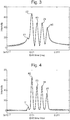
- Fig. 3 shows a Fourier transform of the data in Fig. 2 using a known technique that uses the magnitude mode.
- Fig. 3 shows the intensity of the ion signal as a function of drift time through the IMS device 3.
- the IMS spectrum includes a peak corresponding to each of the five ion species (#1 to #5) modelled. These peaks are labelled in Fig. 3 with their respective ion species.
- Fig. 4 shows a Fourier transform of the data in Fig. 2 according to an embodiment of the present invention that uses the absorption mode.
- the absorption mode spectrum was calculated by assuming that the phase of the oscillation of the signal was identical for each ion species.
- Fig. 4 shows the intensity of the ion signal as a function of drift time through the IMS device 3.
- the IMS spectrum includes a peak corresponding to each of the five ion species (#1 to #5) modelled. The peaks are labelled in Fig. 4 with their respective ion species.
- the absorption mode IMS data according to the embodiment of the present invention and shown in Fig. 4 has higher resolution and better peak shape than the magnitude mode IMS data of the prior art and shown in Fig. 3 . More specifically, the low and high drift time tails of each peak are substantially reduced in Fig. 4 and the peaks are resolved nearly to the baseline (i.e. to a signal intensity of almost zero). The minor intensity peak of ion species #1 at drift time 9.85 ms is clearly resolved according to the absorption mode method of Fig. 4 , whereas it appears as an indistinct shoulder in the magnitude mode method of Fig. 3 .
- the inventors of the present invention have recognised that, theoretically, all of the signals recorded using the FT-IMS device have the same phase and that therefore no phase correction is required in order to calculate and use the absorption mode spectrum to accurately determine the ion mobilities of the ions.
- variations in pressure, temperature or other changes in the experimental environment during the frequency scan of the voltage applied to the ion gates may result in distortions of the ideal signal. This may prevent the accurate calculation of the IMS spectrum.
- a change in temperature or pressure may result in a time-dependent stretching of the data obtained in the ion gate voltage frequency domain.
- the data may be corrected (prior to being Fourier transformed or subjected to other data processing techniques) using information from gauges or sensors, or by using internal standards.
- the FT-IMS instrument may be coupled with a mass spectrometer and an internal standard having a known mass to charge ratio may be used to obtain a pure signal at the known mass to charge ratio.
- the pure signal may then be extracted and used to determine the necessary correction to the data due to changes in the environmental conditions.
- the internal standard may, for example, be any sufficiently pure species present in the analyte.
- phase function may be determined and phase correction may be required.
- the phase function may be determined by examining the frequency and phase of the ion signal for specific species of ions having known mass to charge ratios and/or known ion mobilities.
- a set of ion species having no interferences may be examined. This may be performed by only introducing a set of ion species having no interferences into the FT-IMS device, or by identifying a set of ion species having no interference in the analyte. These species may then be used as calibration standards.
- phase function which relates the phase of an ion signal to the frequency of the ion signal.
- the phase function may then be used in subsequent analysis to correct the phase for all of the components of the ion signal, thereby producing an absorption spectrum with higher IMS resolution.
- the FT-IMS device has been described as being coupled with a mass spectrometer, this is not essential.
Landscapes
- Chemical & Material Sciences (AREA)
- Physics & Mathematics (AREA)
- Analytical Chemistry (AREA)
- Life Sciences & Earth Sciences (AREA)
- Electrochemistry (AREA)
- Health & Medical Sciences (AREA)
- Chemical Kinetics & Catalysis (AREA)
- Spectroscopy & Molecular Physics (AREA)
- Biochemistry (AREA)
- General Health & Medical Sciences (AREA)
- General Physics & Mathematics (AREA)
- Immunology (AREA)
- Pathology (AREA)
- Other Investigation Or Analysis Of Materials By Electrical Means (AREA)
- Spectrometry And Color Measurement (AREA)
Claims (15)
- Verfahren zur Ionenmobilitätsspektrometrie, umfassend:Übertragen von Ionen an einen lonenmobilitätsseparator (3);Modulieren der Einführung der Ionen in den lonenmobilitätsseparator (3) mit einer ersten Modulationsfrequenz;Trennen der in den lonenmobilitätsseparator (3) eintretenden Ionen entsprechend der Ionenmobilität;Detektieren von aus dem lonenmobilitätsseparator (3) ausgetretenen Ionen mit einem Detektor (5);wobei die Übertragung von Ionen vom lonenmobilitätsseparator (3) zum Detektor (5) mit einer zweiten Modulationsfrequenz moduliert wird, oder der Detektorausgang mit einer zweiten Modulationsfrequenz moduliert wird, so dass der Detektor (5) ein moduliertes Signal ausgibt;Variieren der ersten und zweiten Modulationsfrequenz mit der Zeit;Aufzeichnen der Intensität des modulierten Signals in Abhängigkeit von der ersten oder zweiten Modulationsfrequenz, um Daten in einem Modulationsfrequenzbereich zu erhalten; undDurchführen einer Fourier-Transformation der Daten, um komplexe Spektraldaten in einem Driftzeitbereich zu erzeugen; und gekennzeichnet durch:Erzeugen von Absorptionsspektraldaten, die für ein Absorptionsspektrum der komplexen Spektraldaten repräsentativ sind; undBestimmen der lonenmobilitäten der Ionen aus den Absorptionsspektraldaten.
- Verfahren nach Anspruch 1, wobei zu jedem Zeitpunkt die erste Frequenz gleich der zweiten Frequenz ist und wobei die erste und zweite Frequenz zusammen mit der Zeit variiert werden.
- Verfahren nach Anspruch 1 oder 2, wobei das Absorptionsspektrum der Realteil der komplexen Spektraldaten ist.
- Verfahren nach einem der vorstehenden Ansprüche, umfassend das Bereitstellen eines loneneingangsgatters (2) am Eingang des lonenmobilitätsseparators (3) und das Aufbringen einer Wechselspannung an das loneneingangsgatter (2), die periodisch zwischen einem Potential, welches die Übertragung von Ionen in den lonenmobilitätsseparator (3) blockiert, und einem Potential, welches ermöglicht, dass Ionen in den lonenmobilitätsseparator (3) übertragen werden, variiert, wobei die Frequenz der Wechselspannung die erste Modulationsfrequenz ist; und/oder
Bereitstellen eines lonenausgangsgatters (4) am Ausgang des lonenmobilitätsseparators (3) und Aufbringen einer Wechselspannung an das lonenausgangsgatter (4), die periodisch zwischen einem Potential, welches die Übertragung von Ionen aus dem lonenmobilitätsseparator (3) blockiert, und einem Potential, welches ermöglicht, dass Ionen aus dem lonenmobilitätsseparator (3) übertragen werden, variiert, wobei die Frequenz der Wechselspannung die zweite Modulationsfrequenz ist. - Verfahren nach Anspruch 4, wobei die Wechselspannung, die auf das loneneingangsgatter (2) aufgebracht wird, dieselbe ist wie die Wechselspannung, die zu einem beliebigen Zeitpunkt auf das lonenausgangsgatter (4) aufgebracht wird.
- Verfahren nach einem der vorstehenden Ansprüche, wobei die Modulationsfrequenz mit der Zeit stufenweise erhöht oder erniedrigt wird, und wobei eine Verzögerungszeit bereitgestellt wird, nachdem die Modulationsfrequenz auf einen neuen Wert gestuft wurde.
- Verfahren nach einem der vorstehenden Ansprüche, wobei das lonensignal im Modulationsfrequenzbereich für ein Ion mit einer gegebenen lonenmobilität periodisch mit einer Frequenz variiert, die für die lonenmobilität dieses Ions charakteristisch ist.
- Verfahren nach einem der vorstehenden Ansprüche, umfassend das Bereitstellen eines lonenmobilitätsspektrums aus den Absorptionsspektraldaten, wobei das lonenmobilitätsspektrum die lonensignalamplitude der Ionen in Abhängigkeit der Driftzeit durch den lonenmobilitätsseparator (3) repräsentiert.
- Verfahren nach einem der vorstehenden Ansprüche, umfassend das Messen des Wertes eines Parameters der experimentellen Umgebung oder der experimentellen Bedingungen, während die Modulationsfrequenz variiert wird, wobei der Parameter das Modulationsfrequenzbereichssignal oder die komplexen Daten beeinflusst, und das Korrigieren des Modulationsfrequenzbereichssignals oder der komplexen Daten basierend auf dem Wert des Parameters.
- Verfahren nach Anspruch 9, wobei der Parameter die Temperatur oder der Druck der experimentellen Umgebung ist.
- Verfahren nach einem der vorstehenden Ansprüche, wobei ein oder mehrere Kalibrierionen analysiert werden und das lonensignal oder die komplexen Daten für andere Ionen basierend auf der Analyse der Kalibrierionen korrigiert werden.
- Ionenmobilitätsspektrometer, umfassend:einen lonenmobilitätsseparator (3) zum Trennen von Ionen entsprechend der Ionenmobilität;eine Vorrichtung zum Übertragen von Ionen an den lonenmobilitätsseparator (3);einen ersten Modulator, der so konfiguriert ist, dass er die Einführung von Ionen in den lonenmobilitätsseparator (3) mit einer ersten Modulationsfrequenz moduliert;einen lonendetektor (5), der zum Detektieren von aus dem lonenmobilitätsseparator (3) ausgetretenen Ionen eingerichtet ist;einen zweiten Modulator zum Modulieren der Übertragung von Ionen vom lonenmobilitätsseparator (3) zum Detektor (5) mit einer zweiten Modulationsfrequenz oder zum Modulieren eines vom Detektor (5) ausgegebenen lonensignals mit einer zweiten Modulationsfrequenz, so dass der Detektor (5) ein moduliertes Signal ausgibt; undeine Steuerung, die eingerichtet und angepasst ist zum:Variieren der ersten und zweiten Modulationsfrequenz mit der Zeit;Aufzeichnen der Intensität des modulierten Signals in Abhängigkeit von der ersten oder zweiten Modulationsfrequenz, um Daten in dem Modulationsfrequenzbereich zu erhalten; undDurchführen einer Fourier-Transformation der Daten, um komplexe Spektraldaten in einem Driftzeitbereich zu erzeugen; dadurch gekennzeichnet, dass die Steuerung weiter eingerichtet und angepasst ist zum:Erzeugen von Absorptionsspektraldaten, die für ein Absorptionsspektrum der komplexen Spektraldaten repräsentativ sind; undBestimmen der lonenmobilitäten der Ionen aus den Absorptionsspektraldaten.
- Spektrometer nach Anspruch 12, wobei der erste Modulator ein loneneingangsgatter (2) ist, das konfiguriert ist, um die Einführung von Ionen in den lonenmobilitätsseparator (3) mit der ersten Modulationsfrequenz zu modulieren; und/oder wobei der zweite Modulator ein lonenausgangsgatter (4) ist, das konfiguriert ist, um den Austritt von Ionen aus dem lonenmobilitätsseparator (3) zum Detektor (5) mit der zweiten Modulationsfrequenz zu modulieren.
- Verfahren zur Ionenmobilitätsspektrometrie, umfassend:Übertragen von Ionen an einen lonenmobilitätsseparator (3);Modulieren der Einführung der Ionen in den lonenmobilitätsseparator (3) mit einer ersten Modulationsfrequenz;Trennen der in den lonenmobilitätsseparator (3) eintretenden Ionen entsprechend der Ionenmobilität;Detektieren von aus dem lonenmobilitätsseparator (3) ausgetretenen Ionen mit einem Detektor (5);Anwenden einer Modulation stromabwärts des lonenmobilitätsseparators (3) mit einer zweiten Modulationsfrequenz, um eine Modulation in den von dem Detektor (5) aufgezeichneten Daten zu verursachen, um modulierte Daten in einem Modulationsfrequenzbereich zu erhalten; wobei die erste und die zweite Modulationsfrequenz mit der Zeit variiert werden;Durchführen einer Fourier-Transformation der modulierten Daten, um komplexe Spektraldaten in einem Driftzeitbereich zu erzeugen; und gekennzeichnet durch:Erzeugen von Absorptionsspektraldaten, die für ein Absorptionsspektrum der komplexen Spektraldaten repräsentativ sind; undBestimmen der lonenmobilitäten der Ionen aus den Absorptionsspektraldaten.
- Ionenmobilitätsspektrometer, umfassend:einen lonenmobilitätsseparator (3) zum Trennen von Ionen entsprechend der Ionenmobilität;eine Vorrichtung zum Übertragen von Ionen an den lonenmobilitätsseparator (3);einen ersten Modulator, der so konfiguriert ist, dass er die Einführung von Ionen in den lonenmobilitätsseparator (3) mit einer ersten Modulationsfrequenz moduliert;einen lonendetektor (5), der zum Detektieren von aus dem lonenmobilitätsseparator (3) ausgetretenen Ionen eingerichtet ist; undeine Steuerung, die eingerichtet und angepasst ist zum:Anwenden einer Modulation stromabwärts des lonenmobilitätsseparators (3) mit einer zweiten Modulationsfrequenz, um eine Modulation in den vom Detektor (5) aufgezeichneten Daten zu verursachen, um modulierte Daten in einem Modulationsfrequenzbereich zu erhalten; wobei die erste und die zweite Modulationsfrequenz mit der Zeit variiert werden; undDurchführen einer Fourier-Transformation der modulierten Daten, um komplexe Spektraldaten in einem Driftzeitbereich zu erzeugen; dadurch gekennzeichnet, dass die Steuerung weiter eingerichtet und angepasst ist zum:Erzeugen von Absorptionsspektraldaten, die für ein Absorptionsspektrum der komplexen Spektraldaten repräsentativ sind; undBestimmen der lonenmobilitäten der Ionen aus den Absorptionsspektraldaten.
Applications Claiming Priority (1)
| Application Number | Priority Date | Filing Date | Title |
|---|---|---|---|
| GBGB1504938.0A GB201504938D0 (en) | 2015-03-24 | 2015-03-24 | Absorption mode FT-IMS |
Publications (3)
| Publication Number | Publication Date |
|---|---|
| EP3073259A2 EP3073259A2 (de) | 2016-09-28 |
| EP3073259A3 EP3073259A3 (de) | 2016-10-05 |
| EP3073259B1 true EP3073259B1 (de) | 2021-07-14 |
Family
ID=53052296
Family Applications (1)
| Application Number | Title | Priority Date | Filing Date |
|---|---|---|---|
| EP16161195.9A Active EP3073259B1 (de) | 2015-03-24 | 2016-03-18 | Absorptionsmodus-ft-ims |
Country Status (3)
| Country | Link |
|---|---|
| US (1) | US9829465B2 (de) |
| EP (1) | EP3073259B1 (de) |
| GB (2) | GB201504938D0 (de) |
Families Citing this family (5)
| Publication number | Priority date | Publication date | Assignee | Title |
|---|---|---|---|---|
| GB201421065D0 (en) * | 2014-11-27 | 2015-01-14 | Shimadzu Corp | Fourier Transform mass spectrometry |
| GB201504934D0 (en) | 2015-03-24 | 2015-05-06 | Micromass Ltd | Improved method of FT-IMS |
| GB201616017D0 (en) * | 2016-09-20 | 2016-11-02 | Micromass Ltd | Improved method ion mobility spectrometry |
| CN108364847A (zh) * | 2018-01-16 | 2018-08-03 | 清华大学深圳研究生院 | 一种连续扫频的傅里叶变换离子迁移谱仪 |
| CN114441622B (zh) * | 2022-01-24 | 2023-09-05 | 湘潭大学 | 一种消除傅里叶解卷积离子迁移谱基线岐变的方法与装置 |
Family Cites Families (5)
| Publication number | Priority date | Publication date | Assignee | Title |
|---|---|---|---|---|
| US4633083A (en) * | 1985-04-08 | 1986-12-30 | Washington State University Research Foundation, Inc. | Chemical analysis by time dispersive ion spectrometry |
| US6580068B1 (en) * | 1999-07-09 | 2003-06-17 | Sandia Corporation | Method and apparatus for time dispersive spectroscopy |
| US7078684B2 (en) * | 2004-02-05 | 2006-07-18 | Florida State University | High resolution fourier transform ion cyclotron resonance (FT-ICR) mass spectrometry methods and apparatus |
| DE102009048063A1 (de) * | 2009-09-30 | 2011-03-31 | Eads Deutschland Gmbh | Ionisationsverfahren, Ionenerzeugungsvorrichtung sowie Verwendung derselben bei der Ionenmobilitätsspektronomie |
| EP2372747B1 (de) * | 2010-03-31 | 2018-08-01 | Thermo Fisher Scientific (Bremen) GmbH | Verfahren und Vorrichtungen zur Massenspektrumserzeugung |
-
2015
- 2015-03-24 GB GBGB1504938.0A patent/GB201504938D0/en not_active Ceased
-
2016
- 2016-03-18 EP EP16161195.9A patent/EP3073259B1/de active Active
- 2016-03-18 GB GB1604624.5A patent/GB2537739B/en active Active
- 2016-03-23 US US15/078,319 patent/US9829465B2/en active Active
Non-Patent Citations (1)
| Title |
|---|
| None * |
Also Published As
| Publication number | Publication date |
|---|---|
| GB2537739A (en) | 2016-10-26 |
| GB201504938D0 (en) | 2015-05-06 |
| US20160284530A1 (en) | 2016-09-29 |
| GB2537739B (en) | 2017-11-22 |
| US9829465B2 (en) | 2017-11-28 |
| EP3073259A3 (de) | 2016-10-05 |
| EP3073259A2 (de) | 2016-09-28 |
| GB201604624D0 (en) | 2016-05-04 |
Similar Documents
| Publication | Publication Date | Title |
|---|---|---|
| US12165860B2 (en) | Two dimensional MS/MS acquisition modes | |
| US9460902B2 (en) | Method of identifying precursor ions | |
| US10886116B2 (en) | Hybrid mass spectrometer | |
| US10079136B2 (en) | Self-calibration of spectra using differences in molecular weight from known charge states | |
| US10727040B2 (en) | Ion profiling with a scanning quadrupole mass filter | |
| US10043644B2 (en) | De-convolution of overlapping ion mobility spectrometer or separator data | |
| EP3073259B1 (de) | Absorptionsmodus-ft-ims | |
| US20170047212A1 (en) | Mass Spectrometer With Interleaved Acquistion | |
| US10304674B2 (en) | Time of flight mass spectrometer | |
| GB2530367A (en) | Monitoring liquid chromatography elution to determine when to perform a lockmass calibration | |
| EP3519805B1 (de) | Mobilitätsanalysator nach trennung und verfahren zur bestimmung von ionenkollisionsquerschnitten | |
| US9818589B2 (en) | Time shift for improved ion mobility spectrometry or separation digitisation | |
| GB2529924A (en) | De-convolution of overlapping ion mobility spectrometer or separator data | |
| GB2530836A (en) | Hybrid mass spectrometer | |
| US9881776B2 (en) | Monitoring liquid chromatography elution to determine when to perform a lockmass calibration | |
| US11733206B2 (en) | Multiplexing method for separators | |
| GB2531846A (en) | Ion profiling with a scanning quadrupole mass filter | |
| GB2533010A (en) | Two dimensional MSMS acquisition modes |
Legal Events
| Date | Code | Title | Description |
|---|---|---|---|
| PUAI | Public reference made under article 153(3) epc to a published international application that has entered the european phase |
Free format text: ORIGINAL CODE: 0009012 |
|
| PUAL | Search report despatched |
Free format text: ORIGINAL CODE: 0009013 |
|
| AK | Designated contracting states |
Kind code of ref document: A2 Designated state(s): AL AT BE BG CH CY CZ DE DK EE ES FI FR GB GR HR HU IE IS IT LI LT LU LV MC MK MT NL NO PL PT RO RS SE SI SK SM TR |
|
| AX | Request for extension of the european patent |
Extension state: BA ME |
|
| AK | Designated contracting states |
Kind code of ref document: A3 Designated state(s): AL AT BE BG CH CY CZ DE DK EE ES FI FR GB GR HR HU IE IS IT LI LT LU LV MC MK MT NL NO PL PT RO RS SE SI SK SM TR |
|
| AX | Request for extension of the european patent |
Extension state: BA ME |
|
| RIC1 | Information provided on ipc code assigned before grant |
Ipc: G01N 27/62 20060101AFI20160829BHEP |
|
| STAA | Information on the status of an ep patent application or granted ep patent |
Free format text: STATUS: REQUEST FOR EXAMINATION WAS MADE |
|
| 17P | Request for examination filed |
Effective date: 20170116 |
|
| RBV | Designated contracting states (corrected) |
Designated state(s): AL AT BE BG CH CY CZ DE DK EE ES FI FR GB GR HR HU IE IS IT LI LT LU LV MC MK MT NL NO PL PT RO RS SE SI SK SM TR |
|
| STAA | Information on the status of an ep patent application or granted ep patent |
Free format text: STATUS: EXAMINATION IS IN PROGRESS |
|
| 17Q | First examination report despatched |
Effective date: 20171201 |
|
| GRAP | Despatch of communication of intention to grant a patent |
Free format text: ORIGINAL CODE: EPIDOSNIGR1 |
|
| STAA | Information on the status of an ep patent application or granted ep patent |
Free format text: STATUS: GRANT OF PATENT IS INTENDED |
|
| INTG | Intention to grant announced |
Effective date: 20200922 |
|
| GRAJ | Information related to disapproval of communication of intention to grant by the applicant or resumption of examination proceedings by the epo deleted |
Free format text: ORIGINAL CODE: EPIDOSDIGR1 |
|
| STAA | Information on the status of an ep patent application or granted ep patent |
Free format text: STATUS: EXAMINATION IS IN PROGRESS |
|
| GRAP | Despatch of communication of intention to grant a patent |
Free format text: ORIGINAL CODE: EPIDOSNIGR1 |
|
| INTC | Intention to grant announced (deleted) | ||
| STAA | Information on the status of an ep patent application or granted ep patent |
Free format text: STATUS: GRANT OF PATENT IS INTENDED |
|
| INTG | Intention to grant announced |
Effective date: 20210218 |
|
| GRAS | Grant fee paid |
Free format text: ORIGINAL CODE: EPIDOSNIGR3 |
|
| GRAA | (expected) grant |
Free format text: ORIGINAL CODE: 0009210 |
|
| STAA | Information on the status of an ep patent application or granted ep patent |
Free format text: STATUS: THE PATENT HAS BEEN GRANTED |
|
| AK | Designated contracting states |
Kind code of ref document: B1 Designated state(s): AL AT BE BG CH CY CZ DE DK EE ES FI FR GR HR HU IE IS IT LI LT LU LV MC MK MT NL NO PL PT RO RS SE SI SK SM TR |
|
| RBV | Designated contracting states (corrected) |
Designated state(s): AL AT BE BG CH CY CZ DE DK EE ES FI FR GR HR HU IE IS IT LI LT LU LV MC MK MT NL NO PL PT RO RS SE SI SK SM TR |
|
| REG | Reference to a national code |
Ref country code: DE Ref legal event code: R096 Ref document number: 602016060531 Country of ref document: DE |
|
| REG | Reference to a national code |
Ref country code: IE Ref legal event code: FG4D |
|
| REG | Reference to a national code |
Ref country code: AT Ref legal event code: REF Ref document number: 1411053 Country of ref document: AT Kind code of ref document: T Effective date: 20210815 |
|
| REG | Reference to a national code |
Ref country code: LT Ref legal event code: MG9D |
|
| REG | Reference to a national code |
Ref country code: NL Ref legal event code: MP Effective date: 20210714 |
|
| REG | Reference to a national code |
Ref country code: AT Ref legal event code: MK05 Ref document number: 1411053 Country of ref document: AT Kind code of ref document: T Effective date: 20210714 |
|
| PG25 | Lapsed in a contracting state [announced via postgrant information from national office to epo] |
Ref country code: RS Free format text: LAPSE BECAUSE OF FAILURE TO SUBMIT A TRANSLATION OF THE DESCRIPTION OR TO PAY THE FEE WITHIN THE PRESCRIBED TIME-LIMIT Effective date: 20210714 Ref country code: SE Free format text: LAPSE BECAUSE OF FAILURE TO SUBMIT A TRANSLATION OF THE DESCRIPTION OR TO PAY THE FEE WITHIN THE PRESCRIBED TIME-LIMIT Effective date: 20210714 Ref country code: HR Free format text: LAPSE BECAUSE OF FAILURE TO SUBMIT A TRANSLATION OF THE DESCRIPTION OR TO PAY THE FEE WITHIN THE PRESCRIBED TIME-LIMIT Effective date: 20210714 Ref country code: BG Free format text: LAPSE BECAUSE OF FAILURE TO SUBMIT A TRANSLATION OF THE DESCRIPTION OR TO PAY THE FEE WITHIN THE PRESCRIBED TIME-LIMIT Effective date: 20211014 Ref country code: AT Free format text: LAPSE BECAUSE OF FAILURE TO SUBMIT A TRANSLATION OF THE DESCRIPTION OR TO PAY THE FEE WITHIN THE PRESCRIBED TIME-LIMIT Effective date: 20210714 Ref country code: LT Free format text: LAPSE BECAUSE OF FAILURE TO SUBMIT A TRANSLATION OF THE DESCRIPTION OR TO PAY THE FEE WITHIN THE PRESCRIBED TIME-LIMIT Effective date: 20210714 Ref country code: NL Free format text: LAPSE BECAUSE OF FAILURE TO SUBMIT A TRANSLATION OF THE DESCRIPTION OR TO PAY THE FEE WITHIN THE PRESCRIBED TIME-LIMIT Effective date: 20210714 Ref country code: PT Free format text: LAPSE BECAUSE OF FAILURE TO SUBMIT A TRANSLATION OF THE DESCRIPTION OR TO PAY THE FEE WITHIN THE PRESCRIBED TIME-LIMIT Effective date: 20211115 Ref country code: NO Free format text: LAPSE BECAUSE OF FAILURE TO SUBMIT A TRANSLATION OF THE DESCRIPTION OR TO PAY THE FEE WITHIN THE PRESCRIBED TIME-LIMIT Effective date: 20211014 Ref country code: ES Free format text: LAPSE BECAUSE OF FAILURE TO SUBMIT A TRANSLATION OF THE DESCRIPTION OR TO PAY THE FEE WITHIN THE PRESCRIBED TIME-LIMIT Effective date: 20210714 Ref country code: FI Free format text: LAPSE BECAUSE OF FAILURE TO SUBMIT A TRANSLATION OF THE DESCRIPTION OR TO PAY THE FEE WITHIN THE PRESCRIBED TIME-LIMIT Effective date: 20210714 |
|
| PG25 | Lapsed in a contracting state [announced via postgrant information from national office to epo] |
Ref country code: PL Free format text: LAPSE BECAUSE OF FAILURE TO SUBMIT A TRANSLATION OF THE DESCRIPTION OR TO PAY THE FEE WITHIN THE PRESCRIBED TIME-LIMIT Effective date: 20210714 Ref country code: LV Free format text: LAPSE BECAUSE OF FAILURE TO SUBMIT A TRANSLATION OF THE DESCRIPTION OR TO PAY THE FEE WITHIN THE PRESCRIBED TIME-LIMIT Effective date: 20210714 Ref country code: GR Free format text: LAPSE BECAUSE OF FAILURE TO SUBMIT A TRANSLATION OF THE DESCRIPTION OR TO PAY THE FEE WITHIN THE PRESCRIBED TIME-LIMIT Effective date: 20211015 |
|
| REG | Reference to a national code |
Ref country code: DE Ref legal event code: R097 Ref document number: 602016060531 Country of ref document: DE |
|
| PG25 | Lapsed in a contracting state [announced via postgrant information from national office to epo] |
Ref country code: DK Free format text: LAPSE BECAUSE OF FAILURE TO SUBMIT A TRANSLATION OF THE DESCRIPTION OR TO PAY THE FEE WITHIN THE PRESCRIBED TIME-LIMIT Effective date: 20210714 |
|
| PLBE | No opposition filed within time limit |
Free format text: ORIGINAL CODE: 0009261 |
|
| STAA | Information on the status of an ep patent application or granted ep patent |
Free format text: STATUS: NO OPPOSITION FILED WITHIN TIME LIMIT |
|
| PG25 | Lapsed in a contracting state [announced via postgrant information from national office to epo] |
Ref country code: SM Free format text: LAPSE BECAUSE OF FAILURE TO SUBMIT A TRANSLATION OF THE DESCRIPTION OR TO PAY THE FEE WITHIN THE PRESCRIBED TIME-LIMIT Effective date: 20210714 Ref country code: SK Free format text: LAPSE BECAUSE OF FAILURE TO SUBMIT A TRANSLATION OF THE DESCRIPTION OR TO PAY THE FEE WITHIN THE PRESCRIBED TIME-LIMIT Effective date: 20210714 Ref country code: RO Free format text: LAPSE BECAUSE OF FAILURE TO SUBMIT A TRANSLATION OF THE DESCRIPTION OR TO PAY THE FEE WITHIN THE PRESCRIBED TIME-LIMIT Effective date: 20210714 Ref country code: EE Free format text: LAPSE BECAUSE OF FAILURE TO SUBMIT A TRANSLATION OF THE DESCRIPTION OR TO PAY THE FEE WITHIN THE PRESCRIBED TIME-LIMIT Effective date: 20210714 Ref country code: CZ Free format text: LAPSE BECAUSE OF FAILURE TO SUBMIT A TRANSLATION OF THE DESCRIPTION OR TO PAY THE FEE WITHIN THE PRESCRIBED TIME-LIMIT Effective date: 20210714 Ref country code: AL Free format text: LAPSE BECAUSE OF FAILURE TO SUBMIT A TRANSLATION OF THE DESCRIPTION OR TO PAY THE FEE WITHIN THE PRESCRIBED TIME-LIMIT Effective date: 20210714 |
|
| 26N | No opposition filed |
Effective date: 20220419 |
|
| PG25 | Lapsed in a contracting state [announced via postgrant information from national office to epo] |
Ref country code: IT Free format text: LAPSE BECAUSE OF FAILURE TO SUBMIT A TRANSLATION OF THE DESCRIPTION OR TO PAY THE FEE WITHIN THE PRESCRIBED TIME-LIMIT Effective date: 20210714 |
|
| PG25 | Lapsed in a contracting state [announced via postgrant information from national office to epo] |
Ref country code: MC Free format text: LAPSE BECAUSE OF FAILURE TO SUBMIT A TRANSLATION OF THE DESCRIPTION OR TO PAY THE FEE WITHIN THE PRESCRIBED TIME-LIMIT Effective date: 20210714 |
|
| REG | Reference to a national code |
Ref country code: CH Ref legal event code: PL |
|
| REG | Reference to a national code |
Ref country code: BE Ref legal event code: MM Effective date: 20220331 |
|
| PG25 | Lapsed in a contracting state [announced via postgrant information from national office to epo] |
Ref country code: LU Free format text: LAPSE BECAUSE OF NON-PAYMENT OF DUE FEES Effective date: 20220318 Ref country code: LI Free format text: LAPSE BECAUSE OF NON-PAYMENT OF DUE FEES Effective date: 20220331 Ref country code: IE Free format text: LAPSE BECAUSE OF NON-PAYMENT OF DUE FEES Effective date: 20220318 Ref country code: FR Free format text: LAPSE BECAUSE OF NON-PAYMENT OF DUE FEES Effective date: 20220331 Ref country code: CH Free format text: LAPSE BECAUSE OF NON-PAYMENT OF DUE FEES Effective date: 20220331 |
|
| PG25 | Lapsed in a contracting state [announced via postgrant information from national office to epo] |
Ref country code: BE Free format text: LAPSE BECAUSE OF NON-PAYMENT OF DUE FEES Effective date: 20220331 |
|
| P01 | Opt-out of the competence of the unified patent court (upc) registered |
Effective date: 20230506 |
|
| PG25 | Lapsed in a contracting state [announced via postgrant information from national office to epo] |
Ref country code: HU Free format text: LAPSE BECAUSE OF FAILURE TO SUBMIT A TRANSLATION OF THE DESCRIPTION OR TO PAY THE FEE WITHIN THE PRESCRIBED TIME-LIMIT; INVALID AB INITIO Effective date: 20160318 |
|
| PG25 | Lapsed in a contracting state [announced via postgrant information from national office to epo] |
Ref country code: MK Free format text: LAPSE BECAUSE OF FAILURE TO SUBMIT A TRANSLATION OF THE DESCRIPTION OR TO PAY THE FEE WITHIN THE PRESCRIBED TIME-LIMIT Effective date: 20210714 Ref country code: CY Free format text: LAPSE BECAUSE OF FAILURE TO SUBMIT A TRANSLATION OF THE DESCRIPTION OR TO PAY THE FEE WITHIN THE PRESCRIBED TIME-LIMIT Effective date: 20210714 |
|
| PG25 | Lapsed in a contracting state [announced via postgrant information from national office to epo] |
Ref country code: MT Free format text: LAPSE BECAUSE OF FAILURE TO SUBMIT A TRANSLATION OF THE DESCRIPTION OR TO PAY THE FEE WITHIN THE PRESCRIBED TIME-LIMIT Effective date: 20210714 |
|
| PG25 | Lapsed in a contracting state [announced via postgrant information from national office to epo] |
Ref country code: TR Free format text: LAPSE BECAUSE OF FAILURE TO SUBMIT A TRANSLATION OF THE DESCRIPTION OR TO PAY THE FEE WITHIN THE PRESCRIBED TIME-LIMIT Effective date: 20210714 |
|
| PGFP | Annual fee paid to national office [announced via postgrant information from national office to epo] |
Ref country code: DE Payment date: 20260219 Year of fee payment: 11 |