EP3519604B1 - Composant nucléaire a substrat metallique, procédé de fabrication par dli-mocvd et utilisations contre l'oxydation/hydruration - Google Patents
Composant nucléaire a substrat metallique, procédé de fabrication par dli-mocvd et utilisations contre l'oxydation/hydruration Download PDFInfo
- Publication number
- EP3519604B1 EP3519604B1 EP17793686.1A EP17793686A EP3519604B1 EP 3519604 B1 EP3519604 B1 EP 3519604B1 EP 17793686 A EP17793686 A EP 17793686A EP 3519604 B1 EP3519604 B1 EP 3519604B1
- Authority
- EP
- European Patent Office
- Prior art keywords
- chromium
- mixed
- precursor
- silicon
- nuclear component
- Prior art date
- Legal status (The legal status is an assumption and is not a legal conclusion. Google has not performed a legal analysis and makes no representation as to the accuracy of the status listed.)
- Active
Links
Images


Classifications
-
- C—CHEMISTRY; METALLURGY
- C23—COATING METALLIC MATERIAL; COATING MATERIAL WITH METALLIC MATERIAL; CHEMICAL SURFACE TREATMENT; DIFFUSION TREATMENT OF METALLIC MATERIAL; COATING BY VACUUM EVAPORATION, BY SPUTTERING, BY ION IMPLANTATION OR BY CHEMICAL VAPOUR DEPOSITION, IN GENERAL; INHIBITING CORROSION OF METALLIC MATERIAL OR INCRUSTATION IN GENERAL
- C23C—COATING METALLIC MATERIAL; COATING MATERIAL WITH METALLIC MATERIAL; SURFACE TREATMENT OF METALLIC MATERIAL BY DIFFUSION INTO THE SURFACE, BY CHEMICAL CONVERSION OR SUBSTITUTION; COATING BY VACUUM EVAPORATION, BY SPUTTERING, BY ION IMPLANTATION OR BY CHEMICAL VAPOUR DEPOSITION, IN GENERAL
- C23C16/00—Chemical coating by decomposition of gaseous compounds, without leaving reaction products of surface material in the coating, i.e. chemical vapour deposition [CVD] processes
- C23C16/02—Pretreatment of the material to be coated
- C23C16/0272—Deposition of sub-layers, e.g. to promote the adhesion of the main coating
-
- C—CHEMISTRY; METALLURGY
- C23—COATING METALLIC MATERIAL; COATING MATERIAL WITH METALLIC MATERIAL; CHEMICAL SURFACE TREATMENT; DIFFUSION TREATMENT OF METALLIC MATERIAL; COATING BY VACUUM EVAPORATION, BY SPUTTERING, BY ION IMPLANTATION OR BY CHEMICAL VAPOUR DEPOSITION, IN GENERAL; INHIBITING CORROSION OF METALLIC MATERIAL OR INCRUSTATION IN GENERAL
- C23C—COATING METALLIC MATERIAL; COATING MATERIAL WITH METALLIC MATERIAL; SURFACE TREATMENT OF METALLIC MATERIAL BY DIFFUSION INTO THE SURFACE, BY CHEMICAL CONVERSION OR SUBSTITUTION; COATING BY VACUUM EVAPORATION, BY SPUTTERING, BY ION IMPLANTATION OR BY CHEMICAL VAPOUR DEPOSITION, IN GENERAL
- C23C16/00—Chemical coating by decomposition of gaseous compounds, without leaving reaction products of surface material in the coating, i.e. chemical vapour deposition [CVD] processes
- C23C16/06—Chemical coating by decomposition of gaseous compounds, without leaving reaction products of surface material in the coating, i.e. chemical vapour deposition [CVD] processes characterised by the deposition of metallic material
- C23C16/18—Chemical coating by decomposition of gaseous compounds, without leaving reaction products of surface material in the coating, i.e. chemical vapour deposition [CVD] processes characterised by the deposition of metallic material from metallo-organic compounds
-
- C—CHEMISTRY; METALLURGY
- C23—COATING METALLIC MATERIAL; COATING MATERIAL WITH METALLIC MATERIAL; CHEMICAL SURFACE TREATMENT; DIFFUSION TREATMENT OF METALLIC MATERIAL; COATING BY VACUUM EVAPORATION, BY SPUTTERING, BY ION IMPLANTATION OR BY CHEMICAL VAPOUR DEPOSITION, IN GENERAL; INHIBITING CORROSION OF METALLIC MATERIAL OR INCRUSTATION IN GENERAL
- C23C—COATING METALLIC MATERIAL; COATING MATERIAL WITH METALLIC MATERIAL; SURFACE TREATMENT OF METALLIC MATERIAL BY DIFFUSION INTO THE SURFACE, BY CHEMICAL CONVERSION OR SUBSTITUTION; COATING BY VACUUM EVAPORATION, BY SPUTTERING, BY ION IMPLANTATION OR BY CHEMICAL VAPOUR DEPOSITION, IN GENERAL
- C23C16/00—Chemical coating by decomposition of gaseous compounds, without leaving reaction products of surface material in the coating, i.e. chemical vapour deposition [CVD] processes
- C23C16/04—Coating on selected surface areas, e.g. using masks
- C23C16/045—Coating cavities or hollow spaces, e.g. interior of tubes; Infiltration of porous substrates
-
- C—CHEMISTRY; METALLURGY
- C23—COATING METALLIC MATERIAL; COATING MATERIAL WITH METALLIC MATERIAL; CHEMICAL SURFACE TREATMENT; DIFFUSION TREATMENT OF METALLIC MATERIAL; COATING BY VACUUM EVAPORATION, BY SPUTTERING, BY ION IMPLANTATION OR BY CHEMICAL VAPOUR DEPOSITION, IN GENERAL; INHIBITING CORROSION OF METALLIC MATERIAL OR INCRUSTATION IN GENERAL
- C23C—COATING METALLIC MATERIAL; COATING MATERIAL WITH METALLIC MATERIAL; SURFACE TREATMENT OF METALLIC MATERIAL BY DIFFUSION INTO THE SURFACE, BY CHEMICAL CONVERSION OR SUBSTITUTION; COATING BY VACUUM EVAPORATION, BY SPUTTERING, BY ION IMPLANTATION OR BY CHEMICAL VAPOUR DEPOSITION, IN GENERAL
- C23C16/00—Chemical coating by decomposition of gaseous compounds, without leaving reaction products of surface material in the coating, i.e. chemical vapour deposition [CVD] processes
- C23C16/06—Chemical coating by decomposition of gaseous compounds, without leaving reaction products of surface material in the coating, i.e. chemical vapour deposition [CVD] processes characterised by the deposition of metallic material
- C23C16/08—Chemical coating by decomposition of gaseous compounds, without leaving reaction products of surface material in the coating, i.e. chemical vapour deposition [CVD] processes characterised by the deposition of metallic material from metal halides
- C23C16/10—Deposition of chromium only
-
- C—CHEMISTRY; METALLURGY
- C23—COATING METALLIC MATERIAL; COATING MATERIAL WITH METALLIC MATERIAL; CHEMICAL SURFACE TREATMENT; DIFFUSION TREATMENT OF METALLIC MATERIAL; COATING BY VACUUM EVAPORATION, BY SPUTTERING, BY ION IMPLANTATION OR BY CHEMICAL VAPOUR DEPOSITION, IN GENERAL; INHIBITING CORROSION OF METALLIC MATERIAL OR INCRUSTATION IN GENERAL
- C23C—COATING METALLIC MATERIAL; COATING MATERIAL WITH METALLIC MATERIAL; SURFACE TREATMENT OF METALLIC MATERIAL BY DIFFUSION INTO THE SURFACE, BY CHEMICAL CONVERSION OR SUBSTITUTION; COATING BY VACUUM EVAPORATION, BY SPUTTERING, BY ION IMPLANTATION OR BY CHEMICAL VAPOUR DEPOSITION, IN GENERAL
- C23C16/00—Chemical coating by decomposition of gaseous compounds, without leaving reaction products of surface material in the coating, i.e. chemical vapour deposition [CVD] processes
- C23C16/22—Chemical coating by decomposition of gaseous compounds, without leaving reaction products of surface material in the coating, i.e. chemical vapour deposition [CVD] processes characterised by the deposition of inorganic material, other than metallic material
- C23C16/30—Deposition of compounds, mixtures or solid solutions, e.g. borides, carbides, nitrides
- C23C16/32—Carbides
- C23C16/325—Silicon carbide
-
- C—CHEMISTRY; METALLURGY
- C23—COATING METALLIC MATERIAL; COATING MATERIAL WITH METALLIC MATERIAL; CHEMICAL SURFACE TREATMENT; DIFFUSION TREATMENT OF METALLIC MATERIAL; COATING BY VACUUM EVAPORATION, BY SPUTTERING, BY ION IMPLANTATION OR BY CHEMICAL VAPOUR DEPOSITION, IN GENERAL; INHIBITING CORROSION OF METALLIC MATERIAL OR INCRUSTATION IN GENERAL
- C23C—COATING METALLIC MATERIAL; COATING MATERIAL WITH METALLIC MATERIAL; SURFACE TREATMENT OF METALLIC MATERIAL BY DIFFUSION INTO THE SURFACE, BY CHEMICAL CONVERSION OR SUBSTITUTION; COATING BY VACUUM EVAPORATION, BY SPUTTERING, BY ION IMPLANTATION OR BY CHEMICAL VAPOUR DEPOSITION, IN GENERAL
- C23C16/00—Chemical coating by decomposition of gaseous compounds, without leaving reaction products of surface material in the coating, i.e. chemical vapour deposition [CVD] processes
- C23C16/22—Chemical coating by decomposition of gaseous compounds, without leaving reaction products of surface material in the coating, i.e. chemical vapour deposition [CVD] processes characterised by the deposition of inorganic material, other than metallic material
- C23C16/30—Deposition of compounds, mixtures or solid solutions, e.g. borides, carbides, nitrides
- C23C16/34—Nitrides
- C23C16/345—Silicon nitride
-
- C—CHEMISTRY; METALLURGY
- C23—COATING METALLIC MATERIAL; COATING MATERIAL WITH METALLIC MATERIAL; CHEMICAL SURFACE TREATMENT; DIFFUSION TREATMENT OF METALLIC MATERIAL; COATING BY VACUUM EVAPORATION, BY SPUTTERING, BY ION IMPLANTATION OR BY CHEMICAL VAPOUR DEPOSITION, IN GENERAL; INHIBITING CORROSION OF METALLIC MATERIAL OR INCRUSTATION IN GENERAL
- C23C—COATING METALLIC MATERIAL; COATING MATERIAL WITH METALLIC MATERIAL; SURFACE TREATMENT OF METALLIC MATERIAL BY DIFFUSION INTO THE SURFACE, BY CHEMICAL CONVERSION OR SUBSTITUTION; COATING BY VACUUM EVAPORATION, BY SPUTTERING, BY ION IMPLANTATION OR BY CHEMICAL VAPOUR DEPOSITION, IN GENERAL
- C23C16/00—Chemical coating by decomposition of gaseous compounds, without leaving reaction products of surface material in the coating, i.e. chemical vapour deposition [CVD] processes
- C23C16/22—Chemical coating by decomposition of gaseous compounds, without leaving reaction products of surface material in the coating, i.e. chemical vapour deposition [CVD] processes characterised by the deposition of inorganic material, other than metallic material
- C23C16/30—Deposition of compounds, mixtures or solid solutions, e.g. borides, carbides, nitrides
- C23C16/34—Nitrides
- C23C16/347—Carbon nitride
-
- C—CHEMISTRY; METALLURGY
- C23—COATING METALLIC MATERIAL; COATING MATERIAL WITH METALLIC MATERIAL; CHEMICAL SURFACE TREATMENT; DIFFUSION TREATMENT OF METALLIC MATERIAL; COATING BY VACUUM EVAPORATION, BY SPUTTERING, BY ION IMPLANTATION OR BY CHEMICAL VAPOUR DEPOSITION, IN GENERAL; INHIBITING CORROSION OF METALLIC MATERIAL OR INCRUSTATION IN GENERAL
- C23C—COATING METALLIC MATERIAL; COATING MATERIAL WITH METALLIC MATERIAL; SURFACE TREATMENT OF METALLIC MATERIAL BY DIFFUSION INTO THE SURFACE, BY CHEMICAL CONVERSION OR SUBSTITUTION; COATING BY VACUUM EVAPORATION, BY SPUTTERING, BY ION IMPLANTATION OR BY CHEMICAL VAPOUR DEPOSITION, IN GENERAL
- C23C16/00—Chemical coating by decomposition of gaseous compounds, without leaving reaction products of surface material in the coating, i.e. chemical vapour deposition [CVD] processes
- C23C16/22—Chemical coating by decomposition of gaseous compounds, without leaving reaction products of surface material in the coating, i.e. chemical vapour deposition [CVD] processes characterised by the deposition of inorganic material, other than metallic material
- C23C16/30—Deposition of compounds, mixtures or solid solutions, e.g. borides, carbides, nitrides
- C23C16/36—Carbonitrides
-
- C—CHEMISTRY; METALLURGY
- C23—COATING METALLIC MATERIAL; COATING MATERIAL WITH METALLIC MATERIAL; CHEMICAL SURFACE TREATMENT; DIFFUSION TREATMENT OF METALLIC MATERIAL; COATING BY VACUUM EVAPORATION, BY SPUTTERING, BY ION IMPLANTATION OR BY CHEMICAL VAPOUR DEPOSITION, IN GENERAL; INHIBITING CORROSION OF METALLIC MATERIAL OR INCRUSTATION IN GENERAL
- C23C—COATING METALLIC MATERIAL; COATING MATERIAL WITH METALLIC MATERIAL; SURFACE TREATMENT OF METALLIC MATERIAL BY DIFFUSION INTO THE SURFACE, BY CHEMICAL CONVERSION OR SUBSTITUTION; COATING BY VACUUM EVAPORATION, BY SPUTTERING, BY ION IMPLANTATION OR BY CHEMICAL VAPOUR DEPOSITION, IN GENERAL
- C23C16/00—Chemical coating by decomposition of gaseous compounds, without leaving reaction products of surface material in the coating, i.e. chemical vapour deposition [CVD] processes
- C23C16/44—Chemical coating by decomposition of gaseous compounds, without leaving reaction products of surface material in the coating, i.e. chemical vapour deposition [CVD] processes characterised by the method of coating
- C23C16/448—Chemical coating by decomposition of gaseous compounds, without leaving reaction products of surface material in the coating, i.e. chemical vapour deposition [CVD] processes characterised by the method of coating characterised by the method used for generating reactive gas streams, e.g. by evaporation or sublimation of precursor materials
- C23C16/4486—Chemical coating by decomposition of gaseous compounds, without leaving reaction products of surface material in the coating, i.e. chemical vapour deposition [CVD] processes characterised by the method of coating characterised by the method used for generating reactive gas streams, e.g. by evaporation or sublimation of precursor materials by producing an aerosol and subsequent evaporation of the droplets or particles
-
- C—CHEMISTRY; METALLURGY
- C23—COATING METALLIC MATERIAL; COATING MATERIAL WITH METALLIC MATERIAL; CHEMICAL SURFACE TREATMENT; DIFFUSION TREATMENT OF METALLIC MATERIAL; COATING BY VACUUM EVAPORATION, BY SPUTTERING, BY ION IMPLANTATION OR BY CHEMICAL VAPOUR DEPOSITION, IN GENERAL; INHIBITING CORROSION OF METALLIC MATERIAL OR INCRUSTATION IN GENERAL
- C23C—COATING METALLIC MATERIAL; COATING MATERIAL WITH METALLIC MATERIAL; SURFACE TREATMENT OF METALLIC MATERIAL BY DIFFUSION INTO THE SURFACE, BY CHEMICAL CONVERSION OR SUBSTITUTION; COATING BY VACUUM EVAPORATION, BY SPUTTERING, BY ION IMPLANTATION OR BY CHEMICAL VAPOUR DEPOSITION, IN GENERAL
- C23C16/00—Chemical coating by decomposition of gaseous compounds, without leaving reaction products of surface material in the coating, i.e. chemical vapour deposition [CVD] processes
- C23C16/56—After-treatment
-
- G—PHYSICS
- G21—NUCLEAR PHYSICS; NUCLEAR ENGINEERING
- G21C—NUCLEAR REACTORS
- G21C3/00—Reactor fuel elements and their assemblies; Selection of substances for use as reactor fuel elements
- G21C3/02—Fuel elements
- G21C3/04—Constructional details
- G21C3/06—Casings; Jackets
- G21C3/07—Casings; Jackets characterised by their material, e.g. alloys
-
- G—PHYSICS
- G21—NUCLEAR PHYSICS; NUCLEAR ENGINEERING
- G21C—NUCLEAR REACTORS
- G21C3/00—Reactor fuel elements and their assemblies; Selection of substances for use as reactor fuel elements
- G21C3/02—Fuel elements
- G21C3/04—Constructional details
- G21C3/16—Details of the construction within the casing
- G21C3/20—Details of the construction within the casing with coating on fuel or on inside of casing; with non-active interlayer between casing and active material with multiple casings or multiple active layers
-
- Y—GENERAL TAGGING OF NEW TECHNOLOGICAL DEVELOPMENTS; GENERAL TAGGING OF CROSS-SECTIONAL TECHNOLOGIES SPANNING OVER SEVERAL SECTIONS OF THE IPC; TECHNICAL SUBJECTS COVERED BY FORMER USPC CROSS-REFERENCE ART COLLECTIONS [XRACs] AND DIGESTS
- Y02—TECHNOLOGIES OR APPLICATIONS FOR MITIGATION OR ADAPTATION AGAINST CLIMATE CHANGE
- Y02E—REDUCTION OF GREENHOUSE GAS [GHG] EMISSIONS, RELATED TO ENERGY GENERATION, TRANSMISSION OR DISTRIBUTION
- Y02E30/00—Energy generation of nuclear origin
- Y02E30/30—Nuclear fission reactors
Definitions
- the present invention belongs to the field of materials used in the nuclear field, in particular materials intended to best withstand the physico-chemical conditions encountered under nominal conditions and during a nuclear reactor accident, such as for example a reactor. Pressurized Water Reactor (PWR) or a Boiling Water Reactor (BWR).
- PWR Pressurized Water Reactor
- BWR Boiling Water Reactor
- the invention relates more particularly to a nuclear component, its manufacturing process and its uses against oxidation and / or hydriding.
- the zirconium alloy constituting current nuclear fuel cladding oxidizes on contact with the water constituting the coolant of PWR or BWR nuclear reactors.
- the service life of the sheaths is in part limited by the maximum acceptable oxide thickness and the associated absorbed hydrogen content.
- the residual thickness of sound and ductile zirconium alloy must be sufficient and / or the fraction of hydrides sufficiently limited to guarantee good residual mechanical properties of the cladding aimed at ensuring optimal containment of the nuclear fuel .
- Very high temperatures are located at the extreme or even above those of high temperatures between 700 ° C and 1200 ° C which are set by accidental regulatory conditions.
- ECR Equivalent Cladding Reacted
- this acceptable residual "ECR" oxidation rate can now be much less than 17% under certain conditions, such as for example a hydrided cladding in service. up to several hundred ppm by mass, which corresponds in practice to a duration of oxidation of the cladding which must not exceed a few minutes at 1200 ° C.
- An improvement in the resistance to oxidation and / or hydriding at very high temperature would advantageously make it possible to obtain additional safety margins, in particular by preventing or further delaying the deterioration of the cladding in the event of deterioration or deterioration. persistence of the accidental situation.
- One of the aims of the invention is therefore to avoid or reduce one or more of the drawbacks described above, by providing a nuclear component and its manufacturing process which improves resistance to oxidation and / or hydriding. , especially in the presence of water vapor.
- Another aim of the invention may be to improve this resistance to oxidation and / or hydriding at high temperature between 700 ° C and 1200 ° C, or even at very high temperature above 1200 ° C; especially when these temperatures are reached with a rate of temperature rise which is between 0.1 ° C / second and 300 ° C / seconds.
- Another object of the invention may be to improve the duration of resistance to oxidation and / or hydriding, a period beyond which the integrity of the nuclear component, in particular the confinement of the nuclear fuel, n is more assured.
- Another aim of the invention may be to improve the industrialization potential of the manufacturing process, in particular by proposing a process which is both flexible in use, economical and more respectful of the environment.
- the present invention thus relates to a method of manufacturing a nuclear component by the method described in claim 1.
- the manufacturing process of the invention improves in particular the resistance of a nuclear component with respect to oxidation and / or hydriding, while offering a deposit process with high industrialization potential increased by the possibility of recycling.
- the manufacturing process of the invention uses a method of chemical vapor deposition of an organometallic compound by direct liquid injection (known as "DLI-MOCVD” according to the acronym for " Direct Liquid Injection - Metal Organic Chemical Vapor Deposition " ).
- This method is described for example in the following documents: " F. Maury, A. Douard, S. Delclos, D. Samelor, C. Tendero; Multilayer chromium based coatings grown by atmospheric pressure direct liquid injection CVD Surface and Coatings Technology, 204 (2009) 983-987 “(Reference [1]),” A. Douard, F.
- the principle of the DLI-MOCVD technique is to introduce directly into a chemical vapor deposition chamber, in continuous or pulsed mode, a precursor of the metal to be deposited in vaporized form.
- a stock solution containing at least one organometallic compound as precursor is introduced into an evaporator . It is then broken down into microdroplets to form an aerosol which is vaporized in a flash. Flash evaporation consists in rapidly vaporizing a compound outside the pressure and temperature conditions provided for by its saturated vapor pressure law.
- the evaporator is heated to a temperature such that the precursor and its solvent are vaporized, without however causing decomposition at this stage.
- the temperature is conveniently between the boiling point of the solvent and the decomposition temperature of the precursor and secondarily that of the solvent, for example 200 ° C.
- the injection parameters of the stock solution are preferably set using a computer program. They are adjusted so as to obtain a mist of very fine and numerous droplets, in order to obtain satisfactory flash evaporation under reduced pressure. Liquid injection thus constitutes a well-controlled source of organometallic precursor, not limiting the possibilities of optimizing the parameters of the coating deposition process.
- compositions, structure, geometry and physicochemical characteristics of a coating can in particular be declined according to numerous variants, in particular for a coating such as a protective layer, an intermediate layer, an internal strip.
- the vaporized mother solution is entrained by a flow of inert gas from the evaporator towards the deposition zone of the reactor in which the substrate to be covered has been placed.
- the carrier gas used is preferably preheated to the temperature of the evaporator to obtain more efficient vaporization. It is inert so as not to react with the reagents present, by oxidizing them for example.
- Nitrogen is generally chosen for its low cost, but helium, which benefits from better thermal conductivity, or argon, which has a higher protective power, can also be used.
- the enclosure of the chemical vapor deposition reactor is heated to a deposition temperature of between 300 ° C and 600 ° C.
- the organometallic precursor in particular of the bis (arene) metal type, decomposes without degrading the solvent, in order to avoid as much as possible the production of reaction by-products liable to pollute the enclosure by being deposited. on the walls of the reactor or even on the substrate.
- the temperature can be limited to the temperature of the metal in order to avoid its possible deformation or phase transformation.
- the deposition temperature can be between 350 ° C and 550 ° C.
- the reduced deposition temperature for the DLI-MOCVD process is an advantage over other CVD processes from Vapor phase chromium plating which uses gaseous transition metal halides and operates at temperatures up to 900 ° C.
- the chemical vapor deposition reactor is placed under reduced pressure, at which the main stages of the deposition are carried out, from the vaporization of the mother solution, to the possible collection of the effluent obtained at the end of the process. manufacturing.
- the reduced pressure is generally from a few Torr to a few tens of Torr. These are therefore moderately reduced pressures compared to the pressures of about 10 -3 Torr to 10 -4 Torr of industrial PVD processes which require high vacuum equipment.
- One of the advantages of the DLI-MOCVD deposition process for coating a nuclear component with a protective layer is that the latter can be deposited on the internal surface and / or the external surface of the substrate coated or not with an interlayer.
- the protection of the internal layer of a nuclear component with the manufacturing method of the invention is particularly advantageous when the substrate to be coated has a large dimension, for example in the case of a tubular nuclear fuel cladding of a diameter of 1 cm and a length of about 4 m. It partly responds to the oxidation and / or hydriding problems encountered in a nuclear environment.
- a zirconium alloy fuel cladding is subjected to a sudden rise. temperature and internal pressure which lead to bloating and accelerated oxidation of the sheath.
- the combination of these two phenomena can lead to the bursting of the cladding, and therefore to a rupture of confinement of the nuclear fuel and of the fission products it contains.
- the internal surface of the sheath thus exposed is particularly sensitive to oxidation and to a secondary hydriding, namely a localized massive hydriding which results from the oxygen depletion of the water vapor atmosphere by confinement effect. .
- the cladding can then be degraded by cracking during quenching caused by reflooding of the damaged core, or even during post-quenching mechanical stresses (aftershocks, handling, etc.). This degradation can possibly lead to a loss of efficiency in the cooling of the fuel assemblies and evolve into an uncontrolled degraded situation (“serious accidents”).
- Coating the internal surface of a nuclear fuel cladding with at least one protective layer helps to limit, delay or even avoid internal oxidation and / or secondary hydriding under APRP conditions.
- the substrate on which is deposited at least one protective layer with the manufacturing process of the invention is composed of a metal or one of its base alloys.
- the zirconium-based alloy is Zircaloy-2 or Zircaloy-4.
- the nuclear component manufactured with the method of the invention can comprise an intermediate layer positioned between the substrate and at least one protective layer.
- the support is formed by the combination of the substrate and the interlayer.
- the interlayer can fulfill the function of a diffusion barrier.
- the interlayer can be deposited on the substrate with a wide variety of deposition methods, more particularly by performing deposition by DLI-MOCVD or by plasma-assisted chemical vapor deposition (CVD), on the substrate outer surface and / or on its internal surface.
- deposition methods more particularly by performing deposition by DLI-MOCVD or by plasma-assisted chemical vapor deposition (CVD), on the substrate outer surface and / or on its internal surface.
- CVD plasma-assisted chemical vapor deposition
- the precursor comprising an intermediate material chosen from chromium, tantalum, molybdenum, tungsten, niobium or vanadium may be of bis (arene) type according to the variants indicated in the present description.
- the plasma assisted CVD deposition method is for its part only used for deposition on the outer surface of the substrate, generally when the interlayer is composed of a ceramic material.
- the interlayer is then deposited on the external surface of the substrate by performing the plasma-assisted CVD deposition from a mixture comprising at least one titanium, aluminum or silicon halide and a gaseous precursor of nitrogen.
- a mixture comprising at least one titanium, aluminum or silicon halide and a gaseous precursor of nitrogen.
- the titanium, aluminum or silicon halide is a titanium, aluminum or silicon chloride. It is chosen, for example, from TiCl 4 , AlCl 3 , SiCl 4 or their mixtures.
- the intermediate layer may comprise at least one intermediate material chosen from chromium, tantalum, molybdenum, tungsten, niobium, vanadium, their alloys, a titanium nitride, a titanium carbonitride, a mixed titanium-silicon nitride. , a mixed titanium-silicon carbide, a mixed titanium-silicon carbonitride, a mixed titanium-aluminum nitride, or mixtures thereof.
- the intermediate material composed of a titanium nitride, a titanium carbonitride, a mixed titanium-silicon nitride, a mixed titanium-silicon carbide, a mixed titanium-silicon carbonitride or a mixed titanium-aluminum nitride is a ceramic intermediate material: each of these materials is in general denoted respectively TiN, TiCN, TiSiN, TiSiC, TiSiCN or TiAlN, without this implying any stoichiometry; the nitrogen, carbon, silicon and aluminum atoms generally being inserted in the metal matrix of titanium.
- the thickness of the interlayer is from 1 ⁇ m to 5 ⁇ m.
- the nuclear component manufactured with the method of the invention may further comprise an internal strip placed on the internal surface of said support.
- This internal strip is called a “liner” in English and generally plays the role of a diffusion barrier or improves the robustness of the nuclear component with respect to possible chemical or mechanical interactions.
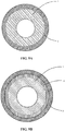
- Said at least one protective layer may be an outer protective layer which coats the outer surface of said support and / or, when the nuclear component comprises an internal volume which may or may not be open, an internal protective layer which coats the internal surface of said support, whether or not coated with the internal strip.
- a nuclear component which comprises an internal volume is for example a nuclear fuel cladding, a guide tube, a plate fuel (the internal volume of which is not open, this component being able nevertheless to be manufactured by the assembly of several parts which can include a surface on which the internal protective layer is deposited, these surfaces forming - after assembly of the parts - the internal surface of the support covered with the protective layer), an absorbent bar.
- the internal strip does not necessarily constitute a coating: it can be a part which is subsequently assembled or fitted into the nuclear component. It can also be obtained by hot co-spinning during the manufacture of the substrate.
- the internal strip can be deposited, at a deposition temperature of between 200 ° C and 400 ° C, on the internal surface of the support by chemical vapor deposition of an organometallic compound (MOCVD) or DLI-MOCVD with for precursor (s) a titanium amide and further a precursor comprising silicon, a precursor comprising aluminum and / or a liquid additive comprising nitrogen as a precursor if the material composing the internal strip respectively comprises silicon , aluminum and / or nitrogen.
- MOCVD organometallic compound
- DLI-MOCVD DLI-MOCVD with for precursor (s) a titanium amide and further a precursor comprising silicon, a precursor comprising aluminum and / or a liquid additive comprising nitrogen as a precursor if the material composing the internal strip respectively comprises silicon , aluminum and / or nitrogen.
- MOCVD deposition method is described for example for the titanium homolog which can be chromium for this MOCVD process in the document " F. Ossola, F. Maury; MOCVD route to chromium carbonitride thin films using Cr (NEt2) 4 as single-source precursor: growth and mechanism., Adv. Check out. Chem. Vap. Deposition, 3 (1997) 137-143 . ”(Reference [6]).
- the liquid additive comprising nitrogen is ammonia, or optionally a molecular precursor comprising a titanium-nitrogen bond.
- a high concentration of the liquid additive comprising nitrogen generally promotes the formation of a nitride to the detriment of a carbide in which the carbon comes from organometallic precursors.
- the deposition temperature by MOCVD or DLI-MOCVD can be between 300 ° C and 400 ° C in order to best promote the proportion of the amorphous structure in the material making up the internal strip and therefore the performance of the internal strip as a barrier broadcast.
- the deposition temperature by MOCVD or DLI-MOCVD can be between 400 ° C and 550 ° C, in order to increase the deposition rate.
- the material making up the internal strip comprises a titanium nitride, a titanium carbonitride, a mixed titanium-silicon nitride, a mixed titanium-silicon carbide, a mixed titanium-silicon carbonitride, a mixed titanium-aluminum nitride, or mixtures thereof.
- the internal strip generally has a thickness of 1 ⁇ m to 10 ⁇ m.
- deposition methods may also be suitable for depositing the internal strip, such as for example a CVD, CVD or DLICVD plasma deposition, as illustrated respectively by the documents " Jin Zhang, Qi Xue and Songxia Li, Microstructure and corrosion behavior of TiC / Ti (CN) / TiN multilayer CVD coatings on high strength steels. Applied Surface Science, 2013. 280: p. 626-631 " (Reference [7]),” A. Weber, C. -P. Klages, ME Gross, RM Charatan and WL Brown, Formation Mechanism of TiN by Reaction of Tetrakis (dimethylamido) -Titanium with Plasma-Activated Nitrogen. Journal of The Electrochemical Society, 1995. 142 (6): p.
- Step a) of vaporization of the mother solution is preferably carried out at a vaporization temperature of between 120 ° C and 220 ° C.
- the stock solution contains a solvent, a bis (arene) type precursor comprising chromium; where appropriate, an additional precursor and a carbon incorporation inhibitor.
- the choice of the solvent contained in the stock solution generally meets several criteria.
- the boiling point of the solvent is lower than the temperature of the evaporator to have flash evaporation in the evaporator. It does not contain oxygen to avoid oxidation of deposits by cracking. It is chemically inert with respect to the precursor in solution and liquid under standard pressure and temperature conditions, namely according to the present description, atmospheric pressure and a temperature of 25 ° C. Finally, the solvent does not decompose significantly in the reactor, in order to be recovered in the effluent at the outlet of the reactor and to avoid or limit any pollution.
- the solvent of the mother solution is a hydrocarbon solvent, namely that it is composed solely of carbon and hydrogen.
- the solvent belongs to a chemical family close to that of the ligands of at least one precursor compound, for example the precursor of bis (arene) type comprising chromium belonging to the family of aromatic hydrocarbons (or arenes).
- this precursor decomposes thermally, releasing its ligands one after the other.
- the by-products of the reaction are therefore essentially free arenes, which will mix with the solvent all the better as they are chemically similar, or even identical. Therefore, the compounds collected in the effluent at the reactor outlet (precursor or reagent not consumed, by-products of the DLI-MOCVD reaction and solvent) are generally aromatic hydrocarbons.
- the solvent is therefore a monocyclic aromatic hydrocarbon, liquid under standard conditions, with a boiling point of less than 150 ° C and a decomposition temperature. above 600 ° C.
- it is chosen from benzene, or a benzene substituted with one or more groups, which are identical or different, independently chosen from a methyl, ethyl or isopropyl group.
- the solvent is toluene, mesitylene (1,3, 5 -trimethylbenzene) or ethylbenzene. It is also possible to use a mixture of these compounds as solvent.
- One of the main constituents of the mother solution is a precursor of bis (arene) type comprising chromium, and, where appropriate, an additional precursor.
- the stock solution contains at least the solvent and the bis (arene) type precursor comprising chromium, the concentration of which can be chosen within a wide range. This concentration mainly influences the rate of deposition according to step b): the more the stock solution is concentrated in precursor, the greater the rate of growth of the coating.
- the concentration of the bis (arene) type precursor comprising chromium in the stock solution can be between 0.1 mol.L -1 and 4.4 mol.L -1 (concentration of the pure precursor), generally between 0.1 mol.L -1 to 1 mol.L -1 , typically 0.35 mol.L -1 .
- the stock solution can also comprise a carbon incorporation inhibitor which prevents or limits the deposition of a protective material comprising carbon: such a material can be a carbide, a mixed carbide , a carbonitride or a mixed carbonitride, these materials possibly comprising, in atomic percentage, 35% carbon and optionally 2% to 3% oxygen often localized on the surface of the protective layer.
- a small amount of carbon can sometimes be deposited with the chromium during step b), without however forming a carbide, even in the presence of the inhibitor.
- the inhibitor is a nucleophilic compound, generally a chlorinated or sulfur additive, devoid of an oxygen atom. Its decomposition temperature is greater than 500 ° C, which prevents or limits the heterogeneous decomposition of the aromatic ligands of the bis (arene) type precursor comprising chromium during which, by dissociation of the metal-ligand bonds of the precursor, a part Hydrocarbon ligands decompose under the catalytic effect of the substrate and contribute their carbons in order to form carbide-type ceramics.
- the inhibitor is a monocyclic aromatic hydrocarbon substituted with a thiol group or at least one chlorine, even more preferably the inhibitor is thiophenol (C 6 H 5 SH) or hexachlorobenzene (C 6 Cl 6 ).
- the inhibitor can be present at a concentration equal to 1% to 10% of the molar concentration of the chromium precursor in the stock solution, for example 2%.
- deposition step b) can be performed in a hot-walled reactor, conventionally used in this field and operating under reduced pressure.
- the reactor as a whole is heated to the temperature required for deposition, so that the walls, the reactive gas phase circulating in the reactor and the substrate to be covered are at the same temperature.
- This type of reactor is also called “isothermal” (or “quasi isothermal", because some temperature gradients may possibly remain).
- a cold wall reactor can also be used, in which only the reactor is not at the deposition temperature but at a lower temperature. In this case, the yield of the reactor, determined from the consumption of precursor, is lower.
- the chemical vapor deposition reactor is at a deposition temperature of between 300 ° C and 600 ° C, so that any bis (arene) type precursor present in the mother solution decomposes without however the solvent does not degrade. This avoids generating by-products liable to pollute the enclosure by being deposited on the walls of the reactor or even on the substrate.
- the deposition temperature according to step b) is preferably between 350 ° C to 550 ° C, even more preferably between 350 ° C and 450 ° C; in order to avoid or further limit any deformations or phase transformations of the substrate when the latter is metallic.
- the deposition temperature according to step b) is between 300 ° C and 400 ° C, which improves the density of the protective layer and promotes its amorphous character, and therefore its resistance to water. oxidation, hydriding and / or migration through the nuclear component of unwanted material such as fissile material.
- Deposition step b) is carried out on the last layer of the support.
- the deposit of the protective layer is produced on the substrate or on the last intermediate layer depending on whether the support respectively contains a bare substrate or one coated with at least one intermediate layer.
- the manufacturing process of the invention can comprise the following step: c) carrying out on said at least one protective layer at least one step chosen from a subsequent step of treatment of ionic or gaseous nitriding, ionic or gaseous siliciding, ionic or gaseous carbosilicide, ionic or gaseous nitriding followed by siliciding or ionic or gaseous carbosilicide.
- This post-treatment step improves the temperature resistance and the tribological properties of the protective layer, more particularly its scratch resistance.
- ionic treatment is a plasma assisted treatment for which the minimum deposition temperature can be around 400 ° C, it is applicable only on the outer surface of a protective layer.
- the minimum deposition temperature for gaseous carbosilicide and gas silicidization is about 900 ° C and about 800 ° C, respectively.
- the silicidation and carburization methods respectively use silane or one of its homologs (Si n H 2n + 2 ) and a hydrocarbon (for example CH 4 , C 3 H 8 , C 2 H 2 or C 2 H 4 ) and can operate, respectively without or with a plasma at a minimum temperature of approximately 800 ° C or 400 ° C.
- steps a), b) and / or c) are carried out with a carrier gas in order to inject any chemical species into the chemical vapor deposition reactor.
- the carrier gas comprises at least one rare gas, most often chemically inert with respect to the various chemical species present in the reactor.
- the rare gas can be chosen from xenon or krypton, but preferably from nitrogen, helium, or argon.
- the carrier gas is for example at a pressure of between 0.2 Pa and 2 Pa.
- the gaseous effluent at the outlet of the chemical vapor deposition reactor comprises precursor molecules, the solvent and, where appropriate, the inhibitor which have not been consumed or pyrolyzed.
- the effluent can also comprise free ligands dissociated from the precursor, which are of the same aromatic family as the solvent. They become part of the base solvent with which they are miscible and themselves act as a solvent.
- a major and unexpected advantage is that the majority of these compounds at the outlet of the low temperature reactor are monocyclic aromatic molecules, generally with a chemical structure similar to or identical to that of the initial compounds which are the precursor or the solvent. It is therefore interesting to collect them.
- the manufacturing process of the present invention by virtue of its characteristics, allows such recycling and can therefore operate in a closed cycle, which has many advantages: reduction or even elimination of the discharge of substances harmful to the environment, economic gain per use. optimum precursors and, as shown below, increased hardness of the protective coating.
- the support is coated with at least one protective layer.
- This protective coating makes it possible in particular to fight against oxidation, hydriding, and / or migration of any unwanted material inside or outside the nuclear component such as, for example, any fissile material obtained from nuclear fuel.
- the protective materials which can be deposited by the manufacturing process of the invention are varied. They are described below.
- the chromium carbide is no longer amorphous but polycrystalline.
- the stock solution contains the bis (arene) type precursor comprising chromium, an additional precursor chosen from a bis (arene) type precursor comprising vanadium, a bis (arene) type precursor arene) comprising niobium, a precursor comprising aluminum or the mixture of these additional precursors; such that a protective material comprising a chromium alloy selected from a chromium / vanadium alloy, a chromium / niobium alloy, a chromium / vanadium / niobium alloy or a chromium / aluminum alloy is obtained in the presence of the inhibitor or that 'a protective material comprising a carbide of the chromium alloy selected from a carbide of a chromium / vanadium alloy, a carbide of a chromium / niobium alloy, a carbide of a chromium / vanadium / niobium alloy or a chromium /
- the carbide of the chromium alloy results from the incorporation of carbon into one of the aforementioned chromium alloys, forming an insertion carbide: it is therefore a carbide of the chromium / vanadium alloy, of a carbide of the chromium / niobium alloy, of a carbide of the chromium / vanadium / niobium alloy or of a carbide of the chromium / aluminum alloy (preferably the mixed Cr 2 AlC carbide of the "MAX phase" type ), which can respectively be denoted CrVC, CrNbC, CrVNbC, CrAlC without this notation referring to any stoichiometry.
- the chromium alloys or their corresponding carbide are mixed alloys or mixed carbides (i.e. they do not include any other metallic element at a significant content, for example a content greater than 0.5 atomic%) and / or they are chromium base alloys or their corresponding chromium base alloy carbide.
- each element within the alloy or its mixed carbide is chosen by those skilled in the art in order to obtain the mechanical properties, including ductility, which are desired in a nuclear environment.
- the atomic content of vanadium or niobium in these alloys can be between 10% and 50%.
- the molar ratios between the bis (arene) type precursor comprising chromium, and the bis (arene) type precursor comprising vanadium or the bis (arene) type precursor comprising niobium are close to or correspond respectively to the ratio stoichiometric in the chromium alloy between chromium, and vanadium or niobium.
- the mother solution contains the bis (arene) type precursor comprising chromium, a liquid precursor comprising nitrogen as additional precursor being present in the mother solution or a gaseous precursor. comprising nitrogen being present in the chemical vapor deposition reactor; such that the protective material comprising a chromium nitride is obtained in the presence of the inhibitor or the protective material comprising a chromium carbonitride is obtained in the absence of the inhibitor.
- a protective material comprising a chromium nitride and / or a chromium carbonitride may further have the advantage of combating the interaction between the internal surface of the cladding (in particular of the substrate) and the nuclear fuel pellet, called pellet-cladding interaction.
- the deposition of the protective layer can be completed by a passivation step aimed at partially oxidizing the protective layer, for example by putting it in the presence of oxygen or water.
- the deposition temperature according to step b) is between 300 ° C and 400 ° C, even more preferably between 300 ° C and 500 ° C, for example 480 ° C, such that the chromium nitride is amorphous.
- chromium carbonitride can be formed with the remaining precursors. A mixture of nitride and carbonitride is then obtained.
- the chromium nitride or the chromium carbonitride is CrN, Cr 2 N or Cr 2 (C, N).
- the nature of the nitride deposited may depend on the ratio R between the partial pressure of the precursor comprising nitrogen and that of the precursor of bis (arene) type comprising chromium: for a given temperature, the hexagonal phase of the Cr 2 N nitride is obtained preferably for the low values of R and the cubic phase of the CrN nitride for the highest values.
- R the ratio between the partial pressure of the precursor comprising nitrogen and that of the precursor of bis (arene) type comprising chromium: for a given temperature, the hexagonal phase of the Cr 2 N nitride is obtained preferably for the low values of R and the cubic phase of the CrN nitride for the highest values.
- Those skilled in the art will also be able to vary the deposition temperature or the deposition pressure in order to promote the production of CrN or Cr 2 N.
- the mother solution contains the bis (arene) type precursor comprising chromium, a precursor comprising silicon as additional precursor; so that at a deposition temperature of between 450 ° C and 500 ° C, the protective material comprising a mixed chromium silicon carbide is obtained.
- the protective material comprising a mixed chromium-silicon carbide may enter into the composition of an interphase layer positioned between a layer of metallic nature and a layer of ceramic nature (for example of a composite material such as SiC / SiC) in order to promote adhesion between these two layers of different nature.
- the mixed chromium-silicon carbide is amorphous, which can for example be favored by an atomic percentage of silicon close to chemical doping (for example an atomic percentage between 1% and 3%) which delays the crystallization of the material. protective and preserves the microstructure of amorphous chromium carbide.
- the amorphous chromium silicon mixed carbide has good durability.
- the amorphous mixed chromium-silicon carbide has the general formula Cr x Si y C z , with the stoichiometric coefficients "x" between 0.60 and 0.70, "y” between 0.01 and 0.05, and "Z" between 0.25 and 0.35.
- the mixed chromium-silicon carbide can be of the “MAX phase” type.
- the MAX phases are here ternary carbides defined by the formula M n + 1 AX n , where M is chromium, A is silicon and X is carbon.
- M is chromium
- A is silicon
- X is carbon.
- This class of materials is characterized by a hexagonal crystal structure containing a stack of nanometric layers, and a low proportion of non-metallic atoms (25%, 33% and 37.5% when n is 1, 2 and 3 respectively). These materials have both a metallic character and properties close to those of ceramics.
- the mixed chromium-silicon carbide of the “MAX phase” type according to the invention preferably contains the silicon atom in an atomic percentage of between 15% and 30%.
- it is chosen from a mixed carbide of formula Cr 2 SiC, Cr 3 SiC 2 , Cr 5 Si 3 C 2 or their mixtures, these carbides comprising in atomic percentage 25% of silicon, 17% of silicon, 30% of silicon and 25% aluminum.
- the mother solution contains the bis (arene) type precursor comprising chromium, a precursor comprising silicon as additional precursor, a liquid precursor comprising nitrogen as precursor additional being present in the mother solution or a gaseous precursor comprising nitrogen being present in the chemical vapor deposition reactor; so that at a deposition temperature between 450 ° C and 550 ° C, the protective material comprising a mixed chromium silicon nitride is obtained in the presence of the inhibitor or the protective material comprising a mixed chromium silicon carbonitride is obtained in the absence of the inhibitor.
- the mixed chromium-silicon carbonitride or the mixed chromium-silicon nitride is amorphous, a structure which is in particular favored by a moderate deposition temperature.
- the mixed chromium-silicon nitride can have the general formula Cr x ' Si y' N w ' , with the stoichiometric coefficients "x'" between 0.23 and 0.57, "y '” between 0.003 and 0.240, and " w '”between 0.42 and 0.56.
- the mixed chromium-silicon carbonitride can have the general formula Cr x " Si y” C z " N w" , with the stoichiometric coefficients "x""between 0.20 and 0.56," y “” between 0.005 and 0.220 , “Z””between 0.05 and 0.34, and” w “" between 0.06 and 0.50.
- the molar percentage of the precursor comprising silicon may be from 10% to 90% in the mother solution, preferably from 10% to 25%, for example 15%.
- the molar percentage is defined here as the ratio between the number of moles of the precursor comprising silicon / (the sum of the number of moles of the precursor comprising silicon and of the precursor of bis (arene) type comprising chromium).
- the precursor comprising nitrogen, whether gaseous or liquid, is generally present in excess amount in the chemical vapor deposition reactor. Its concentration is for example 100 to 200 times greater than that of the bis (arene) type precursor comprising chromium.
- the stock solution also contains, as additional precursors, at least one precursor of bis (arene) type comprising an addition element chosen from yttrium, aluminum, vanadium, niobium, molybdenum, tungsten, a precursor comprising aluminum or yttrium as addition elements or their mixtures; such that the protective material is doped with the addition element.
- bis (arene) type comprising an addition element chosen from yttrium, aluminum, vanadium, niobium, molybdenum, tungsten, a precursor comprising aluminum or yttrium as addition elements or their mixtures; such that the protective material is doped with the addition element.
- This doping can relate to any protective material mentioned in the present description.
- the protective material When the protective material is doped with the addition element, it generally preserves the microstructure of the corresponding undoped protective material within which the addition element is most often in the form of an insertion element or even in certain cases in the form of a substitution element such as for example a substitution of chromium by silicon.
- the protective material comprises the addition element at a content of 1% to 10% atomic. This content increases with the deposition temperature and the molar percentage in the mother solution of the bis (arene) type precursor comprising an addition element which is generally greater than the atomic percentage of the addition element in the protective material.
- the precursors intended to obtain each protective material described above can have a variable composition.
- the element M chosen from chromium, vanadium, niobium or the addition element is present respectively in the bis (arene) type precursor comprising chromium, the bis (arene) type precursor comprising vanadium , the bis (arene) type precursor comprising niobium or the bis (arene) type precursor comprising the addition element.
- Each of these bis (arene) type precursors therefore comprises the corresponding element M.
- the element M is at the zero oxidation degree (M 0 ) in order to have a precursor of bis (arene) type comprising the element M 0 .
- the element M chosen from chromium, tantalum, molybdenum, tungsten, niobium or vanadium present in the bis (arene) type precursor comprising an intermediate material chosen from chromium, tantalum, molybdenum , tungsten, niobium, vanadium, is preferably at zero oxidation degree (M 0 ) in order to have a precursor of bis (arene) type comprising the element M 0 .
- the element M 0 is complexed “in a sandwich” by the organic ligands which are the substituted or unsubstituted arene groups. Since the element M 0 has the same degree of oxidation as in the protective coating which is deposited (the mixed or non-mixed carbides, nitrides, carbonitrides generally being insertion compounds, the element M 0 preserves the degree therein. oxidation), bis (arene) type precursors most often decompose without a complex reaction such as for example an oxidation-reduction reaction generating many by-products.
- the bis (arene) type precursor comprising the element M 0 is a bis (arene) type precursor lacking an oxygen atom of general formula (Ar) (Ar ') M 0 according to which Ar, Ar' , which are identical or different, each independently represent an aromatic group of benzene or benzene type substituted by at least one alkyl group.
- the aromatic groups Ar and Ar 'then each represent a benzene ligand, or a benzene ligand substituted with one to three identical or different groups chosen from a methyl, ethyl or isopropyl group.
- the bis (arene) type precursor comprising the element M 0 can thus be chosen from at least one compound of formula M 0 (C 6 H 6 ) 2 ), M 0 (C 6 H 5 Et) 2 , M 0 ( C 6 H 5 Me) 2 or M 0 (C 6 H 5 iPr) 2 . It then decomposes from around 300 ° C. If it has a decomposition temperature above 600 ° C, it is generally not retained in order to avoid the decomposition of the solvent and limit the formation of by-products. .
- the bis (arene) type precursor comprising the element M 0 has the formula M 0 (C 6 H 5 Et) 2 , since its liquid state under the conditions of vaporization step a) significantly reduces the quantity solvent in the stock solution and thus increase the deposition rate during step b).
- the precursor when the metal is chromium, can be a chromium sandwich compound, such as bis (benzene) chromium (known as BBC, of formula Cr (C 6 H 6 ) 2 ), bis (ethyl-benzene) chromium (called BEBC, of formula Cr (C 6 H 5 Et) 2 ) preferably, bis (methylbenzene) chromium (of formula Cr (C 6 H 5 Me) 2 ), and bis ( cumene) chromium (of formula Cr (C 6 H 5 iPr) 2 ), or a mixture thereof.
- bis (benzene) chromium known as BBC, of formula Cr (C 6 H 6 ) 2
- BEBC of formula Cr (C 6 H 5 Et) 2
- the bis (arene) type precursor comprising the element M 0 can also be an asymmetric derivative of formula (Ar) (Ar ') Cr where Ar and Ar' are different; or a mixture of these chromium bis (arene) which may be rich in one of these compounds.
- Only the BBC is in the form of a powder. It can be injected in the form of a solution, but the concentration is then quickly limited by its low solubility in hydrocarbon solvents.
- the other precursors mentioned are liquid and can be directly injected without solvent, but this does not allow good control of the microstructure of the deposits. Their use in solution is preferred, because this allows a wide variation in the concentration of said solution, a better adjustment of the injection conditions and consequently of the physical properties.
- the stock solution can contain different precursors, without negatively influencing the manufacturing process of the invention.
- the exact nature of the aromatic ligands of the metal is not critical, provided that these ligands preferably belong to the same chemical family of low-substituted monocyclic aromatic compounds.
- the DLI-MOCVD reaction by-products which are derived from the initial reagents can therefore be reintroduced into the chemical vapor deposition reactor, even if the products collected at the reactor outlet exhibit structural variations between them.
- the purity of the initial stock solution is not a critical point either, which makes it possible to use commercial solutions which may for example contain up to 10% of compounds. derivatives.
- the recycled stock solutions which will be used for a subsequent deposition will contain various bis (arene) as precursors.
- the stock solution can therefore contain a mixture of several precursors of different general formulas (Ar) (Ar ') M 0 . Such properties improve the industrialization capabilities of the manufacturing process of the invention.
- the liquid precursor comprising nitrogen is hydrazine and / or the gaseous precursor comprising nitrogen is ammonia.
- the concentration in the chemical vapor deposition reactor of ammonia or hydrazine is respectively 1 to 10 times or 1 to 500 times greater than the concentration of the bis-type precursor. (arena) comprising chromium.
- the precursor comprising silicon may for its part be an organosilane compound which preferably comprises a group of phenylsilane or alkylsilane type.
- the precursor comprising silicon is then chosen from diphenylsilane (C 6 H 5 ) 2 SiH 2 , monophenylsilane (C 6 H 5 ) SiH 3 , diethylsilane (C 2 H 5 ) 2 SiH 2 , triethylsilane (C 2 H 5 ) 3 SiH or their mixtures.
- the precursor comprising aluminum can be a tri (alkyl) aluminum of formula AlR 3 , in which R is for example chosen from CH 3 , C 2 H 5 or C (CH 3 ) 3 .
- the precursor comprising yttrium can also be an amido complex of yttrium, more particularly a tri (amido) yttrium of generic formula YL 3 . It may thus be tris [ N , N -bis (trimethylsilyl) amide] yttrium.
- the protective layer deposited on the support in particular on the substrate not coated with an interlayer, therefore exhibits a wide variety of compositions.
- a protective layer can have a composition gradient: when the protective material is composed of several chemical elements, for example elements A and B for a material of formula AxBy, a composition gradient consists in varying the atomic percentage x or y at least one element A or B depending on the thickness of the coating. This variation can be continuous or stepwise.
- two stock solutions more or less rich in element A or B can be injected simultaneously at a variable rate during the growth of the protective layer using two injectors.
- a protective layer with a composition gradient is particularly advantageous as an interlayer, because it gradually accommodates the mechanical properties of the protective coating to be in better coherence with the corresponding properties of the materials with which it forms the junction.
- the protective material deposited according to a composition gradient is for example the alloy of chromium or its carbide, for example a chromium / vanadium alloy.
- the protective coating comprising at least one protective layer can also have a variety of structures, physicochemical characteristics and / or geometries within one or more layers.
- the protective layer can have a columnar or equiaxial structure.
- the structure is equiaxed when the protective layer has a diffusion barrier function.
- the diffusion barrier property of a protective coating is influenced by its microstructure.
- the anti-diffusion performance of an exogenous chemical element is increasing in the following order: columnar ⁇ equiaxial ⁇ amorphous.
- the grains of the protective material are elongated, as they develop in a preferred direction, generally after the protective layer has reached a critical thickness such as for example a few tens to hundreds of nanometers.
- the columnar structure is also favored by a resumption of growth by epitaxy, generally at high temperature and by causing the stack to grow very rapidly.
- the grains of the protective material also develop in all of their preferred directions of growth.
- the protective layer can also have a particular density. It is for example between 90% and 100% (preferably 95% to 100%) of the density in the solid state of the stable metallic chromium with a cubic crystallographic structure centered according to the space group Im-3m.
- said at least one protective layer has a hardness of between 15 GPa and 30 GPa, preferably between 20 GPa and 29 GPa.
- the density of a protective layer is generally higher when it forms part of a multilayer coating, or is formed at a reduced deposition rate, for example by operating at reduced temperature or pressure.
- the geometry of the protective coating comprising the protective layers can also be variable.
- Each of said at least one protective layer may have a thickness of 1 ⁇ m to 50 ⁇ m, even more preferably from 1 ⁇ m to 25 ⁇ m, or even from 1 ⁇ m to 15 ⁇ m.
- said at least one protective layer may have a thickness of 10 ⁇ m to 50 ⁇ m: this protective layer of minimum thickness promotes resistance to oxidation.
- the cumulative thickness of said protective layers is from 2 ⁇ m to 50 ⁇ m.
- the nuclear component can include from 1 to 50 protective layers.
- the protective coating can also be single-layer or multi-layer.
- Several protective layers of identical or different composition can respectively form a homogeneous multilayer protective coating or a heterogeneous multilayer protective coating.
- the homogeneous multilayer protective coating generally makes it difficult to obtain a columnar structure. It can comprise protective layers composed of partially metastable chromium (its density favoring the role of diffusion barrier of the homogeneous multilayer coating) or of the chromium alloy, for example with a thickness of about 400 nm, or even from 100 nm to 400 nm.
- a multilayer material is distinguished from a single-layer material of equivalent overall chemical composition, in particular by the presence of an interface between the layers.
- This interface is such that it generally corresponds to a disturbance of the microstructure at the atomic scale. It is, for example, identified using a fine characterization technique such as high resolution Transmission Electron Microscopy (TEM), EXAFS (“Extended X-Ray Absorption Fine Structure”) spectroscopy, a Castaing microprobe which gives a composition profile, or even a posteriori by the possible presence of oxide (s) since the interface zone is a preferential oxidation path.
- TEM Transmission Electron Microscopy
- EXAFS Extended X-Ray Absorption Fine Structure
- a multilayer material is generally obtained by a process which performs a sequenced deposition of each monolayer.
- the deposit of each layer can be separated by a pause time, for example between 1 minute to 10 minutes, in order to purge the chemical vapor deposition reactor.
- the last protective layer of the coating is generally a protective layer of ceramic nature (carbide, nitride, carbonitride, mixed or not).
- the nuclear component is a component of the nuclear reactor core, more particularly a nuclear fuel cladding, a spacer grid, a guide tube, a plate fuel or an absorbent bar.
- the nuclear fuel cladding is in the form of a tube or a plate.
- the plate may result more particularly from the assembly of two subunits.
- the invention also relates to a nuclear component obtained or capable of being obtained by the manufacturing process of the invention.
- the invention also relates to a nuclear component as described in claim 7.
- nuclear component namely the nuclear component according to the invention, as well as the nuclear component obtained or capable of being obtained by the manufacturing process of the invention, can be presented according to one or more of the variants described in the present description for the manufacturing process of the invention, in particular the variants relating to the structure, the physicochemical characteristics (such as for example the density), the geometry and / or the composition of the nuclear component.
- the protective material includes a chromium alloy, a carbide of a chromium alloy, a chromium nitride, a chromium carbonitride, a mixed chromium silicon carbide, a mixed chromium silicon nitride, a carbonitride mixed chromium-silicon, or mixtures thereof.
- the invention also relates to the use of these types of nuclear component for combating oxidation and / or hydriding in a humid atmosphere comprising water, in particular in the form of water vapor.
- the invention also relates to the use of these types of nuclear component, for combating hydriding in a hydrogenated atmosphere comprising hydrogen, in particular a hydrogenated atmosphere comprising more than 50 mol% of hydrogen and / or additionally.
- a hydrogenated atmosphere comprising hydrogen, in particular a hydrogenated atmosphere comprising more than 50 mol% of hydrogen and / or additionally.
- water in particular in the form of water vapor (for example at least 25 mol% of water, in particular 25% to 50%).
- the humid atmosphere can comprise from 25% to 100% molar, preferably from 50% to 100% molar, again more preferably from 75% to 100 mol% of water vapor.
- the humid atmosphere or the hydrogenated atmosphere can also comprise an additional gas chosen from air, nitrogen, carbon dioxide or their mixtures.
- a verb such as “understand”, “incorporate”, “include”, “contain”, “composed of” and its conjugated forms are open terms and therefore do not exclude the presence of additional element (s) and / or stage (s) in addition to the initial element (s) and / or stage (s) stated after these terms.
- these open terms also target a particular embodiment in which only the initial element (s) and / or step (s), to the exclusion of any other, are targeted; in which case the open term also covers the closed term “to consist of”, “to constitute of” and its conjugated forms.
- Any coating, layer or strip deposited using the manufacturing process of the invention can coat part or preferably all of the surface on which it rests.
- any alloy is generally a base alloy.
- base alloy is understood to denote the metal entering in particular in the composition of the substrate, of the protective material or of the intermediate material, any alloy based on the metal in which the content of the metal is at least 50% by weight of the metal. metal of the alloy, particularly more than 90% or even more than 95%.
- the base metal is, for example, zirconium, titanium, chromium, tantalum, molybdenum, tungsten, niobium or vanadium.
- An alloy can also contain other chemical elements (for example at a content greater than 0.5 atomic%), in particular a second metallic element, and then constitutes a mixed alloy.
- the inserting carbon element and / or the inserting nitrogen element in an alloy respectively form a carbide of the alloy, a nitride of the alloy or a carbonitride of the alloy, which can also be mixed in the presence of a second metallic element.
- the alloy is preferably suitable for use in the nuclear field and / or under irradiation.
- the following examples of deposition of a coating on a substrate are carried out in a chemical vapor deposition reactor placed in a tube furnace (model marketed by the company CARBOLITE).
- the reactor is made up of a silica tube: it is connected to the gaseous effluent inlet and outlet system by sealed nozzles and to the mother solution by an injector (Vapbox model marketed by the KEMSTREAM company).
- the substrate is not coated with an interlayer.
- these examples can be transposed to the case where the substrate consists of a substrate coated with an intermediate layer.
- the injection parameters essentially act on the rate of deposition and therefore on its thickness by varying the duration of deposition.
- the opening frequency is for example 1 Hz to 10 Hz, commonly 10 Hz.
- the parameters which act on the physico-chemical and structural characteristics of the deposit are essentially the deposit temperature (acting in particular on the structure: amorphous or crystallized; dense or porous; equiaxial or columnar) and the composition of the injected solution.
- the silicon substrate covered with coating number N is called in Table 1 sample N: sample 1 thus designates the silicon substrate covered with coating 1.
- Table 1 ⁇ /u> Coating (N) Solution injected Injection conditions Total deposition pressure (10 +3 Pa) Deposit temperature (° C) Frequency (Hz) Opening time (ms) CrC (1) BEBC (3.5.10 -1 M) + toluene (50 ml) 10 0.5-5 1.3; 6.7 450; 500; 550 Cr (2) BEBC (3.5.10 -1 M) + thiophenol (2 mol%) + toluene (50 ml) 10 0.5-5 6.7 400; 450 CrSiC (3) BEBC (3.5. 10 -1 M) + bis (phenyl) silane (15% molar) + toluene (50 ml) 4 0.5 6.7 450; 500
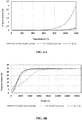
- Table 2 groups together the result of the structural analyzes of these coatings, as well as the result of the temperature resistance tests detailed in the following examples (thermal stability: temperature from which a crystalline phase appears in XRD in situ under argon).
- the atomic composition expressed as an atomic percentage is measured by Castaing microprobe (called “EPMA” for “Electron Probe MicroAnalysis”).
- EPMA Castaing microprobe
- the variation of the injection parameters gives several coating thicknesses, generally lying between 0.5 ⁇ m and 10 ⁇ m: the thicknesses used for the oxidation tests which follow are indicated in Table 2.
- the CrC and CrSiC coatings are amorphous (no crystalline structure), the CrC coating nevertheless being polycrystalline for a deposition temperature of 550 ° C.
- the coatings must withstand the temperature in an oxidizing atmosphere and act as a diffusion barrier.
- amorphous silicon nitride generally Si 3 N 4
- a bare silicon substrate can be passivated by thermal CVD with a mixture (SiH 4 + NH 3 ) or by plasma (PECVD) with NH 3 .
- this sample is heated from 30 ° C to 800 ° C at a temperature rise rate of 5 ° C / minute while being at the same time analyzed by X-ray diffraction (XRD). After natural cooling to 30 ° C, a last X-ray spectrum is recorded.
- XRD X-ray diffraction
- the partially metastable chromium is polycrystalline: it contains a stable phase (Im-3m) and a metastable phase (Pm-3n).
- the metastable phase (Pm-3n) disappears after 450 ° C.
- the stable phase (Im-3m) remains present throughout the heat treatment, the corresponding peaks of DRX become more refined and become more intense thanks to the improvement in crystallinity.
- the sample naturally cools down to 30 ° C: the metastable phase is no longer present, because it has undergone an irreversible transformation. Only the stable phase remains, as well as chromium oxides in small proportions.
- the metallic chromium coating has a temperature resistance under an inert atmosphere in accordance with conventional chromium of centered cubic structure (bcc) stable under normal conditions.
- a 304L stainless steel substrate coated with an amorphous mixed chromium silicon carbide at a deposition temperature of 500 ° C is also analyzed by XRD (acquisitions every 50 ° C from 600 ° C ) when heated from 30 ° C to 1100 ° C.
- the comparative analysis of the XRD spectra for these two samples shows similar behaviors: the amorphous character disappears around 750 ° C. by crystallization of a chromium carbide Cr 7 C 3 and of the compound CrSi 2 . In addition, it shows that since CrSi 2 appears on both substrates, this compound is formed with the silicon of the coating and not that of the substrate, the passivation layer of silicon nitride applied beforehand on the surface of the silicon substrate constituting a barrier. broadcast.
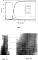
- the elemental composition by mass according to the depth in this sample is then determined for the elements zirconium, chromium, oxygen and carbon by Luminescent Discharge Spectrometry (SDL). She is pictured on the Figure 1 and reveals the presence of a non-zero oxygen level at the interface between the substrate and the coating.
- SDL Luminescent Discharge Spectrometry
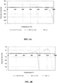
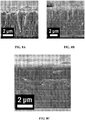
- TEM images shown on the Figures 2A and 2B are carried out using a microscope (JEM 2100 marketed by the company JEOL) equipped with a field emission gun operating at 200 kV: the zones delimited on these images confirm this result of the profile of the Figure 1 , in particular the presence of a layer of zirconium oxide ZrO 2 (zone b) with a thickness of less than 400 nm which is located at the interface between the non-oxidized substrate (zone a) and the coating (zone c).
- JEM 2100 marketed by the company JEOL
- the zones delimited on these images confirm this result of the profile of the Figure 1 , in particular the presence of a layer of zirconium oxide ZrO 2 (zone b) with a thickness of less than 400 nm which is located at the interface between the non-oxidized substrate (zone a) and the coating (zone c).
- EDS energy dispersive spectroscopy
- the zircaloy-4 substrate was already superficially oxidized upon receipt. No other source of oxidation could be identified during the deposition phase of the protective layer of chromium carbide. The sample thus coated did not undergo any further oxidation after storage in air at room temperature conditions.
- the silicon wafer coated with amorphous CrC manufactured according to the conditions of Example 2.1 is subjected to aging in air at 800 ° C. for increasing times of 15, 30, 45, 60, 90, 120 and 180 minutes. For each temperature, the sample is naturally cooled and then analyzed by XRD at room temperature.
- amorphous chromium carbide coating is resistant to oxidation in air at 800 ° C for at least 15 minutes. Beyond these conditions, it begins to oxidize and crystallize.
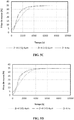
- thermogravimetric analyzes are carried out on plates for ATG (dimensions: 6 mm X 4 mm X 1 mm, plates pierced with d 'a hole of 1 mm in diameter to be suspended from the beam of the ATG balance) of Zircaloy-4 or molybdenum coated by the manufacturing process of the invention with protective layers of different compositions (amorphous CrC, partially metastable Cr or Cr x Si y C z amorphous) and different thicknesses (9 ⁇ m, between 5 ⁇ m and 6 ⁇ m, or between 2 ⁇ m and 3 ⁇ m).
- ATG thermogravimetric analyzes
- the progress of the oxidation of each sample is evaluated by measuring its mass gain (due to the formation of oxide).
- each analysis is repeated on a wafer without a protective layer.
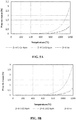
- Zircaloy-4 wafers of different thicknesses (2 ⁇ m, 5 ⁇ m, or 9 ⁇ m) each coated with a protective layer of amorphous CrC are subjected to analysis by ATG in air between 25 ° C and 1200 ° C.
- ATG in air between 25 ° C and 1200 ° C.
- an uncoated Zircaloy-4 wafer is subjected to the same analysis.
- the extent of the oxidation is much less important than that of the bare substrate: the coated substrate takes only about 0.15% by mass against about 3% by mass for the bare substrate, i.e. 20 times more.
- XRD analyzes seem to indicate that three crystalline phases coexist in the coating: crystallized Cr 2 O 3 , amorphous chromium oxides and amorphous CrC chromium carbide.
- the bare substrate immediately oxidizes to ZrO 2 .
- the penetration of oxygen is therefore total in the bare substrate, while it is blocked or greatly limited up to 900 ° C. Beyond this temperature, it becomes partial and progressive in the coated substrates, because the coating of amorphous CrC slows the oxidation kinetics.
- the amorphous CrC coating therefore protects and / or well retards the oxidation of the Zircaloy-4 substrate during heating from 25 ° C to 1200 ° C, even in humid air. This beneficial effect increases with the thickness of the coating.
- Molybdenum platelets of different thicknesses (2 ⁇ m or 5 ⁇ m) each covered with a protective layer of amorphous CrC are subjected to an analysis by ATG in air between 25 ° C and 1200 ° C.
- ATG in air between 25 ° C and 1200 ° C.
- an uncoated molybdenum wafer is subjected to the same analysis.
- the bare molybdenum substrate oxidizes immediately in dry or humid air: above 600 ° C, after a mass gain due to the formation of molybdenum oxide, the bare substrate is then completely destroyed by formation of volatile oxides, which leads to rapid and negative mass losses.
- the amorphous CrC coating therefore protects and / or well retards the oxidation of the molybdenum substrate during heating from 25 ° C to 1100 ° C, even in humid air. This beneficial effect increases with the thickness of the coating.
- Zircaloy-4 wafers are each coated with 9 protective layers of partially metastable Cr in order to form multilayer coatings of different thicknesses (4 ⁇ m or 6 ⁇ m).
- the stacking of the 9 protective layers is carried out by injecting the stock solution for 15 minutes and then stopping it for 5 minutes: a multilayer coating is thus obtained by repeating this deposition / pause cycle 9 times.
- coated platelets are subjected to analysis by ATG in air at 25 ° C to 1200 ° C.
- ATG in air at 25 ° C to 1200 ° C.
- an uncoated Zircaloy-4 wafer is subjected to the same analysis.
- the magnitude of the oxidation is less important than that of the bare substrate: the substrate coated with partially metastable Cr takes only about 0.8% by mass against about 3% by mass for the bare substrate. (ie 3.75 times more), which is however less protective than the coating of amorphous CrC previously analyzed with a mass gain equal to 0.15%.
- the two Zircaloy-4 substrates coated with partially metastable Cr gradually oxidize over time as illustrated by the Figures 5C (dry air) and 5D (humid air).
- the multilayer coating of partially metastable Cr shows in the first seconds an oxidation delay in comparison with the bare substrate, quickly followed by an acceleration of this oxidation.
- the partially metastable Zr / Cr wafer shows less desquamation than the bare Zr wafer, which guarantees better mechanical strength.
- the partially metastable Cr coating prevents or greatly limits the penetration of oxygen up to about 900 ° C, a temperature beyond which this penetration becomes partial and progressive.
- the partially metastable Cr coating therefore protects and / or well retards the oxidation of the Zircaloy-4 substrate.
- a 4 ⁇ m thick Zircaloy-4 wafer covered with a protective layer of amorphous mixed chromium silicon carbide Cr x Si y C z is subjected to an analysis by ATG in dry or humid air between 25 ° C and 1200 ° C with a temperature plateau of 1200 ° C.
- an uncoated Zircaloy-4 wafer is subjected to the same analysis, the oxidation in dry or humid air giving in this case identical results.
- the mass gain changes in a similar way under dry air or under humid air for the Zircaloy-4 substrate coated with mixed chromium silicon carbide Cr x Si y C z amorphous: the oxidation is delayed up to 700 ° C in humid air and 800 ° C in dry air. Compared with the bare substrate, the coated substrate has better resistance to oxidation.
- the Figure 6B (bearing at 1200 ° C) logically shows better resistance to oxidation in dry air than in humid air of the Zircaloy-4 substrate coated with mixed chromium silicon carbide Cr x Si y C z amorphous, without improving this property by compared to bare substrate.
- the Zr / Cr x Si y C z wafer shows less cracking and swelling than the bare Zr wafer, which guarantees better mechanical strength.
- the coating of mixed chromium silicon carbide Cr x Si y C z amorphous therefore protects and / or well retards the oxidation of the Zircaloy-4 substrate. Its resistance to oxidation and its mechanical strength are of intermediate magnitudes to those of amorphous CrC and partially metastable Cr.
- Zircaloy-4 wafers (dimensions: 45 mm X 14 mm X 1 mm) of three different thicknesses (2 ⁇ m to 3 ⁇ m, 5 ⁇ m to 6 ⁇ m, or 9 ⁇ m) each covered with a protective layer of amorphous CrC such as that used in Example 3.3.1 are oxidized in dry air for 14 minutes, then subjected to quenching in water for 10 seconds.
- the amorphous CrC coating therefore protects the Zircaloy-4 substrate against oxidation for the 3 platelets, since no formation of ZrO 2 is detected. Only the coating is partially oxidized to Cr 2 O 3 .
- Table 3 groups together the thicknesses evaluated by SDL for zones A, B, C and D for the three Zr / CrC plates, as well as the corresponding overall mass measurements. ⁇ u> Table 3 ⁇ /u> Initial thickness CrC ( ⁇ m) Zone A: Thickness Cr 2 O 3 ( ⁇ m) Zone B: CrCO transition zone thickness ( ⁇ m) Zone C: CrC thickness ( ⁇ m) Zone D: Diffusion zone thickness in substrate ( ⁇ m) Mass gain (mg. Cm -2 ) 9 1.5 2.5 3 15 0.414 5-6 1.5 2.5 2 11 0.543 2-3 1.5 2.5 1 6 0.288
- Table 3 is supplemented by the Figure 7C which groups together the SEM images of a transverse section for each of the three plates, knowing that the total thickness of the oxidized coating is greater than the thickness of the initial protective coating.
- the SEM image of the 5 ⁇ m to 6 ⁇ m thick wafer shows a crack resulting from accidental decohesion of the initial coating.
- Table 3 and Figure 7C show that the greater the thickness of the initial CrC coating, the thicker the non-oxidized coating (zone C) and the more the diffusion zone of the non-oxidized coating in the substrate (zone D) is too.
- the thickness of the oxidized coating (zone A) does not change: approximately 2 ⁇ m of Cr 2 O 3 and 2 ⁇ m of partially oxidized transition zone (chromium oxycarbide) (zone B).
- the oxidation phenomenon being superficial, and the oxidation conditions being the same, it is consistent that the thickness of Cr 2 O 3 and of the transition zone are identical insofar as all the CrC coating has not been consumed. Oxidation is partial depending on the thickness: less than half of the total thickness of the coating is oxidized for the the thinnest coating (2 ⁇ m to 3 ⁇ m) and a quarter for the thickest (9 ⁇ m).
- the mass gain is most important for the wafer with a protective layer 9 ⁇ m thick, which is also illustrated by the Figure 7C which shows a stronger advance of oxidation within the coating.
- the weight gain ratio between platelets with 9 ⁇ m coating and 2-3 ⁇ m coating is comparable to the ratio of the thicknesses of oxidized coatings: 1.44 versus 1.59.
- non-oxidized coating zone C (amorphous CrC) maintains a very dense microstructure, consisting of small grains of crystallized chromium carbides of submicron size.
- the SDL analysis of the wafer with a thickness of 9 ⁇ m illustrated by the Figure 7D shows a non-significant percentage by mass of hydrogen of 10 ppm in the Zircaloy-4 substrate after oxidation at 1100 ° C followed by quenching with water, which confirms the hydrogen permeation barrier property of the coating of amorphous chromium carbide.
- a nuclear component obtained by the process of fabrication of the invention can maintain a certain mechanical integrity and have a comfortable residual margin of resistance to oxidation / hydriding.
- a nuclear component obtained by the manufacturing process of the invention has improved resistance to oxidation and / or hydriding, in particular at high and very high temperature, in particular in the presence of steam. of water.
- the ⁇ phase of a zirconium alloy (denoted “Zr- ⁇ ”, with a compact hexagonal crystallographic structure) at low temperature is transformed into a ⁇ phase (denoted “Zr- ⁇ ”, with a centered cubic crystallographic structure) in a temperature range typically 700 ° C to 1000 ° C.
- the alloy undergoes local dimensional variations. These variations are a priori unfavorable to the mechanical strength of an outer layer which would cover an inner layer based on zirconium, in particular because of the incompatibility of their expansion coefficients.
- Microstructure of a partially metastable Si / Cr monolayer or multilayer coating 4.
- a passivated silicon substrate is provided with a monolayer coating of chromium which is partially metastable according to the conditions of Example 2.2, or with a multilayer coating of similar thickness and chemical composition, further marking a pause time of 5 minutes. between the deposition of each of the 9 layers constituting the multilayer coating.
- the density of the coating increases progressively by reducing the rate of deposition of the partially metastable chromium by reducing the frequency and the injection time.
- the density of the multilayer coating is estimated at 7.7 ⁇ 0.6 g.cm -3 by RBS analyzes ("Rutherford Backscattering Spectrometry"): taking into account the uncertainties, it is therefore of the same order of magnitude as the optimum density of 7.2 g.cm -3 for stable solid chromium.
- the deposition conditions therefore influence the microstructure of the coating and its density.
- the quality of a coating is inversely proportional to its rate of deposition, as shown by the evolution of a porous columnar growth to a dense equiaxial growth obtained by reducing the rate of deposition.
- the decrease in the deposition rate can be obtained by reducing the deposition temperature, by increasing the deposition pressure or the precursor concentration of the mother solution injected into the CVD deposition reactor.
- nano-indentation experiments are carried out.
- the hardness measurements are carried out on a coating obtained from new precursor (3.5 ⁇ m thick) or from recycled precursor under conditions similar to those set out in Example 6 (1 ⁇ m thick).
- the calculations performed by the measurement and analysis software take into account a Poisson's ratio of the coating of 0.2.
- the “H” and “E” parameters are hardness and Young's modulus.
- the hardness range of a chromium carbide of the state of the art generally varies between 5 GPa and 24 GPa depending on the process used and the deposition conditions.
- the coating thickness is typically 5 ⁇ m.
- a coating of about 1.5 ⁇ m is obtained at the end of N3.
- the BEBC concentration is determined and the yield calculated for N1 and N2 (see Table 5).
- Table 5 ⁇ /u> experience no. solution injected (ml) [BEBC] in the solution injected (g / ml) daughter solution recovered (ml) [BEBC] in the daughter solution (g / ml) yield relative to precursor (%)
- N1 55 0.078 30 0.031 60% N2 50 0.083 30 0.034 59% N3 30 +30 0.040 35 Not measured, because very low N / A
- the nuclear component When the nuclear component is massive or does not define an accessible internal volume, it generally does not include a coating deposited on the internal surface of the substrate.
- the sheath illustrated by Figure 9A comprises a substrate 1, the internal surface of which defines a volume capable of receiving nuclear fuel.
- the substrate 1 forms a support (not coated with an interlayer for this embodiment) on which is placed a protective layer 2 composed of a protective material which improves the resistance to oxidation of the sheath.
- the sheath is also provided with an intermediate layer 3 placed between the substrate 1 and the protective layer 2.
- the combination of the substrate 1 and the intermediate layer 3 forms the support.
- the intermediate layer 3 is composed of at least one intermediate material capable of preventing or limiting the diffusion of the protective material from the protective layer 2 towards the substrate 1.
- the sheath according to the second embodiment is further provided with an internal protective layer 2B in contact with the internal volume of the sheath and here arranged on the internal face of the substrate 1 (therefore not coated with an internal strip for this embodiment).
- the inner protective layer 2B completes the protection conferred by the outer protective layer 2A.
- the sheath according to the third embodiment is further provided with an internal strip 4 positioned between the internal protective layer 2B and the substrate 1.
- the internal strip 4 constitutes a diffusion barrier.
Landscapes
- Chemical & Material Sciences (AREA)
- Engineering & Computer Science (AREA)
- Metallurgy (AREA)
- Mechanical Engineering (AREA)
- General Chemical & Material Sciences (AREA)
- Chemical Kinetics & Catalysis (AREA)
- Materials Engineering (AREA)
- Organic Chemistry (AREA)
- Inorganic Chemistry (AREA)
- Physics & Mathematics (AREA)
- High Energy & Nuclear Physics (AREA)
- General Engineering & Computer Science (AREA)
- Plasma & Fusion (AREA)
- Dispersion Chemistry (AREA)
- Chemical Vapour Deposition (AREA)
Priority Applications (2)
| Application Number | Priority Date | Filing Date | Title |
|---|---|---|---|
| PL17793686T PL3519604T3 (pl) | 2016-09-28 | 2017-09-28 | Element jądrowy z podłożem metalicznym, sposób jego wytwarzania poprzez DLI-MOCVD i zastosowanie przeciw utlenieniu/nawodorowaniu |
| SI201730484T SI3519604T1 (sl) | 2016-09-28 | 2017-09-28 | Jedrska komponenta s kovinskim substratom, postopek za njeno proizvodnjo z DLI-MOCVD in uporabe proti oksidaciji/hidraciji |
Applications Claiming Priority (3)
| Application Number | Priority Date | Filing Date | Title |
|---|---|---|---|
| FR1659275A FR3056815B1 (fr) | 2016-09-28 | 2016-09-28 | Composant nucleaire a substrat metallique et utilisations contre l'oxydation/hydruration. |
| FR1659274A FR3056601B1 (fr) | 2016-09-28 | 2016-09-28 | Procede de fabrication d'un composant nucleaire a substrat metallique par dli-mocvd |
| PCT/FR2017/052655 WO2018060641A1 (fr) | 2016-09-28 | 2017-09-28 | Composant nucléaire a substrat metallique, procédé de fabrication par dli-mocvd et utilisations contre l'oxydation/hydruration |
Publications (2)
| Publication Number | Publication Date |
|---|---|
| EP3519604A1 EP3519604A1 (fr) | 2019-08-07 |
| EP3519604B1 true EP3519604B1 (fr) | 2020-07-29 |
Family
ID=60202268
Family Applications (1)
| Application Number | Title | Priority Date | Filing Date |
|---|---|---|---|
| EP17793686.1A Active EP3519604B1 (fr) | 2016-09-28 | 2017-09-28 | Composant nucléaire a substrat metallique, procédé de fabrication par dli-mocvd et utilisations contre l'oxydation/hydruration |
Country Status (8)
| Country | Link |
|---|---|
| US (2) | US11634810B2 (pl) |
| EP (1) | EP3519604B1 (pl) |
| JP (1) | JP7198746B2 (pl) |
| ES (1) | ES2827830T3 (pl) |
| HU (1) | HUE051186T2 (pl) |
| PL (1) | PL3519604T3 (pl) |
| SI (1) | SI3519604T1 (pl) |
| WO (1) | WO2018060641A1 (pl) |
Families Citing this family (6)
| Publication number | Priority date | Publication date | Assignee | Title |
|---|---|---|---|---|
| EP3520118B1 (fr) | 2016-09-28 | 2020-08-05 | Commissariat à l'Énergie Atomique et aux Énergies Alternatives | Composant nucléaire avec revetement de cr metastable, procédé de fabrication par dli-mocvd et utilisations contre l'oxydation/hydruration |
| JP7198746B2 (ja) | 2016-09-28 | 2023-01-04 | コミサーリャ ア レナジー アトミック エー オー エナジー アルタナティブ | 金属基材を有する原子炉コンポーネント、dli-mocvdによる製造方法および酸化/水素化に対する使用 |
| WO2018060642A1 (fr) | 2016-09-28 | 2018-04-05 | Commissariat A L'energie Atomique Et Aux Energies Alternatives | Composant nucléaire avec revetement de crc amorphe, procédé de fabrication par dli-mocvd et utilisations contre l'oxydation/hydruration |
| JP6735915B2 (ja) | 2016-09-28 | 2020-08-05 | コミサーリャ ア レナジー アトミック エー オー エナジー アルタナティブCommissariat A L’Energie Atomique Et Aux Energies Alternatives | 複合材原子炉コンポーネント、dli−mocvdによる製造方法および酸化/水素化に対する使用 |
| TWI750805B (zh) * | 2019-09-13 | 2021-12-21 | 美商西屋電器公司 | 核燃料護套管及用於製成核燃料護套之方法 |
| US11719865B2 (en) | 2020-03-11 | 2023-08-08 | Apple Inc. | Visible-light-reflecting coatings for electronic devices |
Family Cites Families (24)
| Publication number | Priority date | Publication date | Assignee | Title |
|---|---|---|---|---|
| FR1562862A (pl) | 1967-12-08 | 1969-04-11 | ||
| JPS5940195A (ja) * | 1982-08-31 | 1984-03-05 | 株式会社東芝 | 高速増殖炉用核燃料要素 |
| US5026517A (en) | 1984-12-11 | 1991-06-25 | Siemens Aktiengesellschaft | Nuclear power plant with water or liquid sodium coolant and a metallic component contacting the coolant |
| US4695476A (en) * | 1985-06-06 | 1987-09-22 | Westinghouse Electric Corp. | Process for coating the internal surface of zirconium tubes with neutron absorbers |
| US5154862A (en) * | 1986-03-07 | 1992-10-13 | Thermo Electron Corporation | Method of forming composite articles from CVD gas streams and solid particles of fibers |
| FR2612946B1 (fr) * | 1987-03-27 | 1993-02-19 | Chimie Metal | Procede et installation pour le depot chimique de revetements ultradurs a temperature moderee |
| FR2643087B1 (fr) | 1989-02-16 | 1991-06-07 | Unirec | Procede de depot d'un revetement de type ceramique sur un substrat metallique et element comportant un revetement obtenu par ce procede |
| FR2727691A1 (fr) * | 1994-12-01 | 1996-06-07 | Framatome Sa | Procede de revetement d'un substrat en metal ou alliage passivable, par une couche d'oxyde, et tube de gainage et grille-entretoise pour assemblage combustible revetus d'une couche d'oxyde |
| US7899146B1 (en) * | 2004-06-29 | 2011-03-01 | Sandia Corporation | Porous nuclear fuel element for high-temperature gas-cooled nuclear reactors |
| FR2904006B1 (fr) | 2006-07-21 | 2008-10-31 | Toulouse Inst Nat Polytech | Procede de depot de revetements metalliques durs |
| FR2904007B1 (fr) | 2006-07-21 | 2008-11-21 | Toulouse Inst Nat Polytech | Procede de depot de revetements ceramiques non oxydes. |
| US20090046825A1 (en) * | 2007-08-16 | 2009-02-19 | Ge-Hitachi Nuclear Energy Americas Llc | Protective coating applied to metallic reactor components to reduce corrosion products into the nuclear reactor environment |
| GB0816837D0 (en) * | 2008-09-15 | 2008-10-22 | Element Six Holding Gmbh | A Hard-Metal |
| FR2978697B1 (fr) | 2011-08-01 | 2014-05-16 | Commissariat Energie Atomique | Tube multicouche ameliore en materiau composite a matrice ceramique, gaine de combustible nucleaire en resultant et procedes de fabrication associes |
| FR2989923B1 (fr) | 2012-04-26 | 2014-05-16 | Commissariat Energie Atomique | Materiau multicouche resistant a l'oxydation en milieu nucleaire. |
| KR101405396B1 (ko) | 2012-06-25 | 2014-06-10 | 한국수력원자력 주식회사 | 표면에 혼합층을 포함하는 코팅층이 형성된 지르코늄 합금 및 이의 제조방법 |
| US9589680B2 (en) * | 2013-01-18 | 2017-03-07 | Korea Atomic Energy Research Institute | Nuclear fuel rod for fast reactors including metallic fuel slug coated with protective coating layer and fabrication method thereof |
| US9721676B2 (en) * | 2014-05-27 | 2017-08-01 | Westinghouse Electric Company, Llc | Deposition of a protective coating including metal-containing and chromium-containing layers on zirconium alloy for nuclear power applications |
| FR3025929B1 (fr) * | 2014-09-17 | 2016-10-21 | Commissariat Energie Atomique | Gaines de combustible nucleaire, procedes de fabrication et utilisation contre l'oxydation. |
| FR3045673B1 (fr) | 2015-12-18 | 2020-02-28 | Commissariat A L'energie Atomique Et Aux Energies Alternatives | Procede de depot d'un revetement par dli-mocvd avec recyclage du compose precurseur |
| WO2018060642A1 (fr) | 2016-09-28 | 2018-04-05 | Commissariat A L'energie Atomique Et Aux Energies Alternatives | Composant nucléaire avec revetement de crc amorphe, procédé de fabrication par dli-mocvd et utilisations contre l'oxydation/hydruration |
| EP3520118B1 (fr) | 2016-09-28 | 2020-08-05 | Commissariat à l'Énergie Atomique et aux Énergies Alternatives | Composant nucléaire avec revetement de cr metastable, procédé de fabrication par dli-mocvd et utilisations contre l'oxydation/hydruration |
| JP7198746B2 (ja) | 2016-09-28 | 2023-01-04 | コミサーリャ ア レナジー アトミック エー オー エナジー アルタナティブ | 金属基材を有する原子炉コンポーネント、dli-mocvdによる製造方法および酸化/水素化に対する使用 |
| JP6735915B2 (ja) * | 2016-09-28 | 2020-08-05 | コミサーリャ ア レナジー アトミック エー オー エナジー アルタナティブCommissariat A L’Energie Atomique Et Aux Energies Alternatives | 複合材原子炉コンポーネント、dli−mocvdによる製造方法および酸化/水素化に対する使用 |
-
2017
- 2017-09-28 JP JP2019516697A patent/JP7198746B2/ja active Active
- 2017-09-28 HU HUE17793686A patent/HUE051186T2/hu unknown
- 2017-09-28 WO PCT/FR2017/052655 patent/WO2018060641A1/fr not_active Ceased
- 2017-09-28 ES ES17793686T patent/ES2827830T3/es active Active
- 2017-09-28 SI SI201730484T patent/SI3519604T1/sl unknown
- 2017-09-28 EP EP17793686.1A patent/EP3519604B1/fr active Active
- 2017-09-28 PL PL17793686T patent/PL3519604T3/pl unknown
- 2017-09-28 US US16/337,623 patent/US11634810B2/en active Active
-
2023
- 2023-03-07 US US18/179,564 patent/US20230227967A1/en active Pending
Non-Patent Citations (1)
| Title |
|---|
| None * |
Also Published As
| Publication number | Publication date |
|---|---|
| US20230227967A1 (en) | 2023-07-20 |
| ES2827830T3 (es) | 2021-05-24 |
| HUE051186T2 (hu) | 2021-03-01 |
| JP2019529716A (ja) | 2019-10-17 |
| SI3519604T1 (sl) | 2020-12-31 |
| WO2018060641A1 (fr) | 2018-04-05 |
| PL3519604T3 (pl) | 2021-01-25 |
| EP3519604A1 (fr) | 2019-08-07 |
| US20200032387A1 (en) | 2020-01-30 |
| US11634810B2 (en) | 2023-04-25 |
| JP7198746B2 (ja) | 2023-01-04 |
Similar Documents
| Publication | Publication Date | Title |
|---|---|---|
| EP3519605B1 (fr) | Composant nucléaire avec revetement de crc amorphe, procédé de fabrication par dli-mocvd et utilisation contre l'oxydation/hydruration | |
| EP3520118B1 (fr) | Composant nucléaire avec revetement de cr metastable, procédé de fabrication par dli-mocvd et utilisations contre l'oxydation/hydruration | |
| EP3520119B1 (fr) | Composant nucléaire composite, procédé de fabrication par dli-mocvd et utilisations contre l'oxydation/hydruration | |
| EP3519604B1 (fr) | Composant nucléaire a substrat metallique, procédé de fabrication par dli-mocvd et utilisations contre l'oxydation/hydruration | |
| EP3195323B1 (fr) | Gaine de combustible nucléaire composite, procédé de fabrication et utilisations contre l'oxydation/ hydruration | |
| FR3056815A1 (fr) | Composant nucleaire a substrat metallique et utilisations contre l'oxydation/hydruration. | |
| FR3056601A1 (fr) | Procede de fabrication d'un composant nucleaire a substrat metallique par dli-mocvd. | |
| FR3056602A1 (fr) | Procede de fabrication par dli-mocvd d'un composant nucleaire avec revetement de crc amorphe. | |
| FR3056604A1 (fr) | Procede de fabrication par dli-mocvd d'un composant nucleaire composite. | |
| FR3056816A1 (fr) | Composant nucleaire avec revetement de crc amorphe, utilisations contre l'oxydation/hydruration. | |
| FR3056603A1 (fr) | Procede de fabrication par dli-mocvd d'un composant nucleaire avec revetement de cr metastable. | |
| FR3056817A1 (fr) | Composant nucleaire avec revetement de cr metastable et utilisations contre l'oxydation/hydruration. | |
| FR3056818A1 (fr) | Composant nucleaire composite et utilisations. |
Legal Events
| Date | Code | Title | Description |
|---|---|---|---|
| STAA | Information on the status of an ep patent application or granted ep patent |
Free format text: STATUS: UNKNOWN |
|
| STAA | Information on the status of an ep patent application or granted ep patent |
Free format text: STATUS: THE INTERNATIONAL PUBLICATION HAS BEEN MADE |
|
| PUAI | Public reference made under article 153(3) epc to a published international application that has entered the european phase |
Free format text: ORIGINAL CODE: 0009012 |
|
| STAA | Information on the status of an ep patent application or granted ep patent |
Free format text: STATUS: REQUEST FOR EXAMINATION WAS MADE |
|
| 17P | Request for examination filed |
Effective date: 20190418 |
|
| AK | Designated contracting states |
Kind code of ref document: A1 Designated state(s): AL AT BE BG CH CY CZ DE DK EE ES FI FR GB GR HR HU IE IS IT LI LT LU LV MC MK MT NL NO PL PT RO RS SE SI SK SM TR |
|
| AX | Request for extension of the european patent |
Extension state: BA ME |
|
| RIN1 | Information on inventor provided before grant (corrected) |
Inventor name: LOMELLO, FERNANDO Inventor name: MICHAU, ALEXANDRE Inventor name: BOICHOT, RAPHAEL Inventor name: SCHUSTER, FREDERIC Inventor name: PONS, MICHEL Inventor name: MAURY, FRANCIS |
|
| DAV | Request for validation of the european patent (deleted) | ||
| DAX | Request for extension of the european patent (deleted) | ||
| GRAP | Despatch of communication of intention to grant a patent |
Free format text: ORIGINAL CODE: EPIDOSNIGR1 |
|
| STAA | Information on the status of an ep patent application or granted ep patent |
Free format text: STATUS: GRANT OF PATENT IS INTENDED |
|
| INTG | Intention to grant announced |
Effective date: 20200228 |
|
| GRAS | Grant fee paid |
Free format text: ORIGINAL CODE: EPIDOSNIGR3 |
|
| GRAA | (expected) grant |
Free format text: ORIGINAL CODE: 0009210 |
|
| STAA | Information on the status of an ep patent application or granted ep patent |
Free format text: STATUS: THE PATENT HAS BEEN GRANTED |
|
| AK | Designated contracting states |
Kind code of ref document: B1 Designated state(s): AL AT BE BG CH CY CZ DE DK EE ES FI FR GB GR HR HU IE IS IT LI LT LU LV MC MK MT NL NO PL PT RO RS SE SI SK SM TR |
|
| REG | Reference to a national code |
Ref country code: CH Ref legal event code: EP |
|
| REG | Reference to a national code |
Ref country code: AT Ref legal event code: REF Ref document number: 1295878 Country of ref document: AT Kind code of ref document: T Effective date: 20200815 |
|
| REG | Reference to a national code |
Ref country code: IE Ref legal event code: FG4D Free format text: LANGUAGE OF EP DOCUMENT: FRENCH |
|
| REG | Reference to a national code |
Ref country code: DE Ref legal event code: R096 Ref document number: 602017020726 Country of ref document: DE |
|
| REG | Reference to a national code |
Ref country code: CH Ref legal event code: NV Representative=s name: BOVARD AG PATENT- UND MARKENANWAELTE, CH |
|
| REG | Reference to a national code |
Ref country code: FI Ref legal event code: FGE |
|
| REG | Reference to a national code |
Ref country code: SE Ref legal event code: TRGR |
|
| REG | Reference to a national code |
Ref country code: SK Ref legal event code: T3 Ref document number: E 35551 Country of ref document: SK |
|
| REG | Reference to a national code |
Ref country code: LT Ref legal event code: MG4D |
|
| REG | Reference to a national code |
Ref country code: NL Ref legal event code: MP Effective date: 20200729 |
|
| REG | Reference to a national code |
Ref country code: AT Ref legal event code: MK05 Ref document number: 1295878 Country of ref document: AT Kind code of ref document: T Effective date: 20200729 |
|
| PG25 | Lapsed in a contracting state [announced via postgrant information from national office to epo] |
Ref country code: PT Free format text: LAPSE BECAUSE OF FAILURE TO SUBMIT A TRANSLATION OF THE DESCRIPTION OR TO PAY THE FEE WITHIN THE PRESCRIBED TIME-LIMIT Effective date: 20201130 Ref country code: NO Free format text: LAPSE BECAUSE OF FAILURE TO SUBMIT A TRANSLATION OF THE DESCRIPTION OR TO PAY THE FEE WITHIN THE PRESCRIBED TIME-LIMIT Effective date: 20201029 Ref country code: HR Free format text: LAPSE BECAUSE OF FAILURE TO SUBMIT A TRANSLATION OF THE DESCRIPTION OR TO PAY THE FEE WITHIN THE PRESCRIBED TIME-LIMIT Effective date: 20200729 Ref country code: AT Free format text: LAPSE BECAUSE OF FAILURE TO SUBMIT A TRANSLATION OF THE DESCRIPTION OR TO PAY THE FEE WITHIN THE PRESCRIBED TIME-LIMIT Effective date: 20200729 Ref country code: LT Free format text: LAPSE BECAUSE OF FAILURE TO SUBMIT A TRANSLATION OF THE DESCRIPTION OR TO PAY THE FEE WITHIN THE PRESCRIBED TIME-LIMIT Effective date: 20200729 Ref country code: GR Free format text: LAPSE BECAUSE OF FAILURE TO SUBMIT A TRANSLATION OF THE DESCRIPTION OR TO PAY THE FEE WITHIN THE PRESCRIBED TIME-LIMIT Effective date: 20201030 |
|
| PG25 | Lapsed in a contracting state [announced via postgrant information from national office to epo] |
Ref country code: RS Free format text: LAPSE BECAUSE OF FAILURE TO SUBMIT A TRANSLATION OF THE DESCRIPTION OR TO PAY THE FEE WITHIN THE PRESCRIBED TIME-LIMIT Effective date: 20200729 Ref country code: LV Free format text: LAPSE BECAUSE OF FAILURE TO SUBMIT A TRANSLATION OF THE DESCRIPTION OR TO PAY THE FEE WITHIN THE PRESCRIBED TIME-LIMIT Effective date: 20200729 Ref country code: IS Free format text: LAPSE BECAUSE OF FAILURE TO SUBMIT A TRANSLATION OF THE DESCRIPTION OR TO PAY THE FEE WITHIN THE PRESCRIBED TIME-LIMIT Effective date: 20201129 |
|
| REG | Reference to a national code |
Ref country code: HU Ref legal event code: AG4A Ref document number: E051186 Country of ref document: HU |
|
| PG25 | Lapsed in a contracting state [announced via postgrant information from national office to epo] |
Ref country code: NL Free format text: LAPSE BECAUSE OF FAILURE TO SUBMIT A TRANSLATION OF THE DESCRIPTION OR TO PAY THE FEE WITHIN THE PRESCRIBED TIME-LIMIT Effective date: 20200729 |
|
| REG | Reference to a national code |
Ref country code: DE Ref legal event code: R119 Ref document number: 602017020726 Country of ref document: DE |
|
| PG25 | Lapsed in a contracting state [announced via postgrant information from national office to epo] |
Ref country code: IT Free format text: LAPSE BECAUSE OF FAILURE TO SUBMIT A TRANSLATION OF THE DESCRIPTION OR TO PAY THE FEE WITHIN THE PRESCRIBED TIME-LIMIT Effective date: 20200729 Ref country code: SM Free format text: LAPSE BECAUSE OF FAILURE TO SUBMIT A TRANSLATION OF THE DESCRIPTION OR TO PAY THE FEE WITHIN THE PRESCRIBED TIME-LIMIT Effective date: 20200729 Ref country code: EE Free format text: LAPSE BECAUSE OF FAILURE TO SUBMIT A TRANSLATION OF THE DESCRIPTION OR TO PAY THE FEE WITHIN THE PRESCRIBED TIME-LIMIT Effective date: 20200729 Ref country code: RO Free format text: LAPSE BECAUSE OF FAILURE TO SUBMIT A TRANSLATION OF THE DESCRIPTION OR TO PAY THE FEE WITHIN THE PRESCRIBED TIME-LIMIT Effective date: 20200729 Ref country code: DK Free format text: LAPSE BECAUSE OF FAILURE TO SUBMIT A TRANSLATION OF THE DESCRIPTION OR TO PAY THE FEE WITHIN THE PRESCRIBED TIME-LIMIT Effective date: 20200729 |
|
| REG | Reference to a national code |
Ref country code: ES Ref legal event code: FG2A Ref document number: 2827830 Country of ref document: ES Kind code of ref document: T3 Effective date: 20210524 |
|
| PG25 | Lapsed in a contracting state [announced via postgrant information from national office to epo] |
Ref country code: AL Free format text: LAPSE BECAUSE OF FAILURE TO SUBMIT A TRANSLATION OF THE DESCRIPTION OR TO PAY THE FEE WITHIN THE PRESCRIBED TIME-LIMIT Effective date: 20200729 |
|
| PLBE | No opposition filed within time limit |
Free format text: ORIGINAL CODE: 0009261 |
|
| STAA | Information on the status of an ep patent application or granted ep patent |
Free format text: STATUS: NO OPPOSITION FILED WITHIN TIME LIMIT |
|
| REG | Reference to a national code |
Ref country code: BE Ref legal event code: MM Effective date: 20200930 |
|
| PG25 | Lapsed in a contracting state [announced via postgrant information from national office to epo] |
Ref country code: LU Free format text: LAPSE BECAUSE OF NON-PAYMENT OF DUE FEES Effective date: 20200928 |
|
| 26N | No opposition filed |
Effective date: 20210430 |
|
| PG25 | Lapsed in a contracting state [announced via postgrant information from national office to epo] |
Ref country code: DE Free format text: LAPSE BECAUSE OF NON-PAYMENT OF DUE FEES Effective date: 20210401 |
|
| PG25 | Lapsed in a contracting state [announced via postgrant information from national office to epo] |
Ref country code: IE Free format text: LAPSE BECAUSE OF NON-PAYMENT OF DUE FEES Effective date: 20200928 Ref country code: BE Free format text: LAPSE BECAUSE OF NON-PAYMENT OF DUE FEES Effective date: 20200930 |
|
| GBPC | Gb: european patent ceased through non-payment of renewal fee |
Effective date: 20210928 |
|
| PG25 | Lapsed in a contracting state [announced via postgrant information from national office to epo] |
Ref country code: TR Free format text: LAPSE BECAUSE OF FAILURE TO SUBMIT A TRANSLATION OF THE DESCRIPTION OR TO PAY THE FEE WITHIN THE PRESCRIBED TIME-LIMIT Effective date: 20200729 Ref country code: MT Free format text: LAPSE BECAUSE OF FAILURE TO SUBMIT A TRANSLATION OF THE DESCRIPTION OR TO PAY THE FEE WITHIN THE PRESCRIBED TIME-LIMIT Effective date: 20200729 Ref country code: CY Free format text: LAPSE BECAUSE OF FAILURE TO SUBMIT A TRANSLATION OF THE DESCRIPTION OR TO PAY THE FEE WITHIN THE PRESCRIBED TIME-LIMIT Effective date: 20200729 |
|
| PG25 | Lapsed in a contracting state [announced via postgrant information from national office to epo] |
Ref country code: MK Free format text: LAPSE BECAUSE OF FAILURE TO SUBMIT A TRANSLATION OF THE DESCRIPTION OR TO PAY THE FEE WITHIN THE PRESCRIBED TIME-LIMIT Effective date: 20200729 Ref country code: MC Free format text: LAPSE BECAUSE OF FAILURE TO SUBMIT A TRANSLATION OF THE DESCRIPTION OR TO PAY THE FEE WITHIN THE PRESCRIBED TIME-LIMIT Effective date: 20200729 |
|
| PG25 | Lapsed in a contracting state [announced via postgrant information from national office to epo] |
Ref country code: GB Free format text: LAPSE BECAUSE OF NON-PAYMENT OF DUE FEES Effective date: 20210928 |
|
| REG | Reference to a national code |
Ref country code: CH Ref legal event code: U11 Free format text: ST27 STATUS EVENT CODE: U-0-0-U10-U11 (AS PROVIDED BY THE NATIONAL OFFICE) Effective date: 20251001 |
|
| PGFP | Annual fee paid to national office [announced via postgrant information from national office to epo] |
Ref country code: FI Payment date: 20250922 Year of fee payment: 9 |
|
| PGFP | Annual fee paid to national office [announced via postgrant information from national office to epo] |
Ref country code: PL Payment date: 20250912 Year of fee payment: 9 |
|
| PGFP | Annual fee paid to national office [announced via postgrant information from national office to epo] |
Ref country code: BG Payment date: 20250917 Year of fee payment: 9 Ref country code: HU Payment date: 20250917 Year of fee payment: 9 |
|
| PGFP | Annual fee paid to national office [announced via postgrant information from national office to epo] |
Ref country code: FR Payment date: 20250923 Year of fee payment: 9 |
|
| PGFP | Annual fee paid to national office [announced via postgrant information from national office to epo] |
Ref country code: SE Payment date: 20250922 Year of fee payment: 9 |
|
| PGFP | Annual fee paid to national office [announced via postgrant information from national office to epo] |
Ref country code: CZ Payment date: 20250912 Year of fee payment: 9 |
|
| PGFP | Annual fee paid to national office [announced via postgrant information from national office to epo] |
Ref country code: SK Payment date: 20250918 Year of fee payment: 9 |
|
| PGFP | Annual fee paid to national office [announced via postgrant information from national office to epo] |
Ref country code: SI Payment date: 20250915 Year of fee payment: 9 |
|
| PGFP | Annual fee paid to national office [announced via postgrant information from national office to epo] |
Ref country code: CH Payment date: 20251001 Year of fee payment: 9 |
|
| PGFP | Annual fee paid to national office [announced via postgrant information from national office to epo] |
Ref country code: ES Payment date: 20251020 Year of fee payment: 9 |