EP3518822B1 - Dental suction device with a camera - Google Patents
Dental suction device with a camera Download PDFInfo
- Publication number
- EP3518822B1 EP3518822B1 EP17784869.4A EP17784869A EP3518822B1 EP 3518822 B1 EP3518822 B1 EP 3518822B1 EP 17784869 A EP17784869 A EP 17784869A EP 3518822 B1 EP3518822 B1 EP 3518822B1
- Authority
- EP
- European Patent Office
- Prior art keywords
- suction device
- objective
- suction
- opening
- hose
- Prior art date
- Legal status (The legal status is an assumption and is not a legal conclusion. Google has not performed a legal analysis and makes no representation as to the accuracy of the status listed.)
- Active
Links
- 239000007788 liquid Substances 0.000 claims description 9
- 210000000214 mouth Anatomy 0.000 claims description 8
- 239000002245 particle Substances 0.000 claims description 7
- 238000011282 treatment Methods 0.000 description 8
- 238000000034 method Methods 0.000 description 2
- XLYOFNOQVPJJNP-UHFFFAOYSA-N water Substances O XLYOFNOQVPJJNP-UHFFFAOYSA-N 0.000 description 2
- 239000008280 blood Substances 0.000 description 1
- 210000004369 blood Anatomy 0.000 description 1
- 238000004140 cleaning Methods 0.000 description 1
- 239000011248 coating agent Substances 0.000 description 1
- 238000000576 coating method Methods 0.000 description 1
- 238000005553 drilling Methods 0.000 description 1
- -1 for example saliva Substances 0.000 description 1
- 230000002452 interceptive effect Effects 0.000 description 1
- 238000004519 manufacturing process Methods 0.000 description 1
- 238000001454 recorded image Methods 0.000 description 1
- 210000003296 saliva Anatomy 0.000 description 1
- 239000007787 solid Substances 0.000 description 1
- 239000007921 spray Substances 0.000 description 1
- 238000003860 storage Methods 0.000 description 1
Images
Classifications
-
- A—HUMAN NECESSITIES
- A61—MEDICAL OR VETERINARY SCIENCE; HYGIENE
- A61C—DENTISTRY; APPARATUS OR METHODS FOR ORAL OR DENTAL HYGIENE
- A61C17/00—Devices for cleaning, polishing, rinsing or drying teeth, teeth cavities or prostheses; Saliva removers; Dental appliances for receiving spittle
- A61C17/06—Saliva removers; Accessories therefor
- A61C17/08—Aspiration nozzles
-
- A—HUMAN NECESSITIES
- A61—MEDICAL OR VETERINARY SCIENCE; HYGIENE
- A61C—DENTISTRY; APPARATUS OR METHODS FOR ORAL OR DENTAL HYGIENE
- A61C17/00—Devices for cleaning, polishing, rinsing or drying teeth, teeth cavities or prostheses; Saliva removers; Dental appliances for receiving spittle
- A61C17/06—Saliva removers; Accessories therefor
- A61C17/12—Control devices, e.g. for suction
Definitions
- the present invention relates to a dental aspirator for aspirating liquids and particles from an oral cavity of a patient, with a hollow base body which has an outer surface, an inner surface, a longitudinal axis, a connection opening and a suction opening.
- suction devices are usually used, which are usually formed from a tubular body made of plastic, at the end of which a hose is attached, which in turn is connected to a pump. The interfering liquids and solids are drained through the hose.
- a suction device is not guided and held by the treating dentist or dental surgeon, but by an assistant, because the treating dentist has a drilling tool with one hand and a mirror with the other hand through which he can see the area to be treated, must hold.
- the disadvantage of the procedure described is that the two people have to stand or sit very close to one another around the area to be treated. This can be perceived as annoying for the attending physician, especially when the interventions involved are relatively difficult or demanding fine motor skills.
- a medical suction device in which the inner surface has a mirrored surface that is visible through the suction opening.
- the reflective coating according to the invention enables the user to use the medical suction device both as a suction device for removing liquids and particles and at the same time as a mirror. With the help of such an aspirator, it is now possible for him to carry out the treatment without an assistant.
- the aspirator is also used as an aspirator and used as a mirror. The basic idea of combining the two devices is basically very good, but its possibilities are limited.
- the object of the present invention is to provide a suction device which is improved over the known mirror suction device. This should also offer the opportunity to view the oral cavity during suction. In particular, the aspirator should make it easier to document conditions in the oral cavity or work progress.
- the suction device should be inexpensive to manufacture and easy to use.
- the object is achieved by a suction device with the features of claim 1.
- the suction device has an objective which can be connected to a monitor via which the image recorded by the objective can be displayed.
- a processor or computer is advantageously also provided, via which the images or film sequences or videos recorded via the lens can be stored in a data memory. This enables the treatment process to be documented and, in particular, can also be used to inform the patient.
- the objective can have a device for enlarging or reducing (zoom function or zoom device) the recorded image.
- an actuating means preferably a slide control or a wheel, is provided for controlling this on the side of the suction device, which is connected to the lens and can be operated with just one finger during the treatment.
- the suction device has the actuation means for the zoom device and additionally a button, in particular a push button, for starting or ending video recordings to be recorded or for taking photos.
- the objective itself can form an area of the inner surface of the suction device, for example the lens, but it can also be arranged in a closed recess within the base body. If such a recess is provided, it is closed by a transparent pane through which the lens can film.
- the recess is advantageously completely sealed for hygienic reasons, so that no liquids from the oral cavity or the environment can penetrate into it.
- the suction device can have means for electrical connection in the area of the connection opening. These interact with corresponding means which are provided at one end of the hose.
- the suction device according to the invention can thus be plugged onto the hose and at the same time electrically connected, preferably via a plug connection.
- connection to the monitor can be wireless or wired. If it is wired, corresponding means are advantageously also provided in the area of the hose end. A plug connection is also suitable for this purpose.
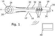
- a suction device 10 has a hollow tubular base body 12 with an inner surface 14 and an outer surface 16.
- the base body 12 also has a longitudinal axis XX.
- the base body 12 has a connection opening 18 for a hose (not shown) and a suction opening 20 for sucking in particles and liquids.
- the liquids or particles to be sucked off are sucked in through the suction opening 20 and discharged through the connection opening 18 via the hose.
- an objective 24 is arranged within the base body 12 in the region of the suction opening 20 and directed in the direction of the oral cavity so that it can be viewed through the objective 24.
- the objective 24 is arranged completely within the base body 12, that is to say behind the suction opening 20 in the direction of flow of the air to be sucked off. The sucked in air is guided over a non-recognizable lens of the objective 24 or a cover of a recess or a cavity in which the objective 24 is located, whereby fogging is effectively prevented.
- the suction device 10 has additional openings 26 through which air is also drawn in.
- the additional openings 26 prevent a negative pressure within the main body 12 when the suction opening 20 is closed, for example, by the patient's tongue or cheek.
- three additional openings 26 are provided, but only a single additional opening 26 or even more than three additional openings 26 is also conceivable.
- profile elements 38 can be seen, which prevent a secure grip of the suction device 10 and the fingers of the dentist performing the treatment from slipping off.
- the objective preferably contains a device for enlarging or reducing (zoom function or zoom device) the image recorded via the objective 24.
- a device for enlarging or reducing (zoom function or zoom device) the image recorded via the objective 24 This can work or be designed analog or digital.
- a slide control 32 is provided on the side of the suction device 10, which can also be operated with just one finger.
- a means 34 is only shown schematically that serves to electrically connect the suction device 10 to an electrical source. For this purpose, a corresponding corresponding means is provided on the hose (not shown).
- connection of the lens 24 to a monitor 40 takes place wirelessly, shown by the line symbol.
- WLAN or Bluetooth are suitable for wireless connections.
Description
Die vorliegende Erfindung betrifft einen zahnmedizinischen Absauger zum Absaugen von Flüssigkeiten und Partikeln aus einem Mundraum eines Patienten, mit einem hohlen Grundkörper, der eine Außenfläche, eine Innenfläche, eine Längsachse, eine Anschlussöffnung und eine Ansaugöffnung aufweist.The present invention relates to a dental aspirator for aspirating liquids and particles from an oral cavity of a patient, with a hollow base body which has an outer surface, an inner surface, a longitudinal axis, a connection opening and a suction opening.
Bei zahnmedizinischen Behandlungen ist es oftmals notwendig, anfallende Flüssigkeiten oder gelöste Partikel, beispielsweise Speichel, Spraywasser und Blut während der Behandlung abzusaugen. Auch kann Wasser, beispielsweise zum Reinigen oder nach Anwenden einer Multifunktionsspritze anfallen, das abgesaugt werden muss. Hierzu werden üblicherweise Absauger verwendet, die in der Regel aus einem röhrenförmigen Körper aus Kunststoff gebildet sind, an dessen Ende ein Schlauch befestigt ist, der wiederum mit einer Pumpe verbunden ist. Durch den Schlauch werden die störenden Flüssigkeiten und Festkörper abgeleitet.In dental treatments, it is often necessary to suck off any liquids or dissolved particles, for example saliva, spray water and blood during the treatment. Water, for example for cleaning or after using a multifunctional syringe, can also be produced and must be suctioned off. For this purpose, suction devices are usually used, which are usually formed from a tubular body made of plastic, at the end of which a hose is attached, which in turn is connected to a pump. The interfering liquids and solids are drained through the hose.
Oftmals wird ein Absauger nicht vom behandelnden Zahnarzt oder Zahnchirurgen selbst, sondern von einer oder einem Assistenten geführt und gehalten, weil der behandelnde Zahnarzt mit der einen Hand ein Bohrwerkzeug und mit der anderen Hand einen Spiegel, über den er den zu behandelnden Bereich einsehen kann, halten muss. Nachteilig bei der beschrieben Vorgehensweise ist, dass die beiden Personen sehr eng beieinander um den zu behandelnden Bereich stehen oder sitzen müssen. Dies kann gerade dann, wenn es sich um verhältnismäßig schwierige oder feinmotorisch anspruchsvolle Eingriffe handelt, für den behandelnden Arzt als störend empfunden werden.Often a suction device is not guided and held by the treating dentist or dental surgeon, but by an assistant, because the treating dentist has a drilling tool with one hand and a mirror with the other hand through which he can see the area to be treated, must hold. The disadvantage of the procedure described is that the two people have to stand or sit very close to one another around the area to be treated. This can be perceived as annoying for the attending physician, especially when the interventions involved are relatively difficult or demanding fine motor skills.
Aus der
Weiter ist aus der Patentschrift
Die Aufgabe der vorliegenden Erfindung besteht darin, einen gegenüber dem bekannten Spiegelsauger verbesserten Absauger bereitzustellen. Dieser soll ebenfalls die Möglichkeit bieten den Mundraum während des Absaugens einzusehen. Insbesondere soll der Absauger das Dokumentieren von Gegebenheiten im Mundraum oder von Arbeitsfortschritten erleichtern. Der Absauger soll dabei kostengünstig herstellbar und einfach zu Bedienen sein.The object of the present invention is to provide a suction device which is improved over the known mirror suction device. This should also offer the opportunity to view the oral cavity during suction. In particular, the aspirator should make it easier to document conditions in the oral cavity or work progress. The suction device should be inexpensive to manufacture and easy to use.
Erfindungsgemäß wird die Aufgabe durch einen Absauger mit den Merkmalen des Patentanspruchs 1 gelöst.According to the invention, the object is achieved by a suction device with the features of claim 1.
Demnach weist der Absauger im Verlauf des Grundkörpers ein Objektiv auf, welches mit einem Monitor verbindbar ist, über den das vom Objektiv aufgenommene Bild darstellbar ist.Accordingly, in the course of the base body, the suction device has an objective which can be connected to a monitor via which the image recorded by the objective can be displayed.
Somit ist es möglich, den zu behandelnden Bereich im Mundraum während der Behandlung einerseits direkt und andererseits indirekt über den Monitor einzusehen.It is thus possible to view the area to be treated in the oral cavity during the treatment on the one hand directly and on the other hand indirectly via the monitor.
Vorteilhafterweise ist weiterhin ein Prozessor oder Rechner vorgesehen, über den die über das Objektiv aufgenommenen Bilder oder Filmsequenzen bzw. Videos auf einen Datenspeicher gespeichert werden können. Dies ermöglicht eine Dokumentation des Behandlungsprozesses und kann insbesondere auch der Information des Patienten dienen.A processor or computer is advantageously also provided, via which the images or film sequences or videos recorded via the lens can be stored in a data memory. This enables the treatment process to be documented and, in particular, can also be used to inform the patient.
Vorteilhafterweise ist es möglich, über einen ebenfalls am Absauger vorgesehenen Betätigungsknopf Einzelbilder oder Videos aufzunehmen und an den Prozessor zur Speicherung weiterzuleiten. Der Behandler kann somit während der Behandlung und ohne diese unterbrechen zu müssen, entscheiden, ob er lediglich das vom Objektiv aufgenommene Bild auf den Monitor übertragen oder ob er dieses aufzeichnen und speichern möchte.It is advantageously possible to record individual images or videos via an actuating button also provided on the suction device and to forward them to the processor for storage. The practitioner can thus decide during the treatment and without having to interrupt it, whether he only wants to transfer the image recorded by the lens to the monitor or whether he would like to record and save it.
Weiterhin kann das Objektiv eine Vorrichtung zum Vergrößern oder Verkleinern (Zoomfunktion bzw. Zoomvorrichtung) des aufgenommenen Bildes aufweisen. In einer besonders vorteilhaften Variante ist zur Steuerung hierzu seitlich am Absauger ein Betätigungsmittel, vorzugsweise ein Schieberegler oder ein Rad vorgesehen, das mit Objektiv verbunden und mit nur einem Finger während der Behandlung bedienbar ist.Furthermore, the objective can have a device for enlarging or reducing (zoom function or zoom device) the recorded image. In In a particularly advantageous variant, an actuating means, preferably a slide control or a wheel, is provided for controlling this on the side of the suction device, which is connected to the lens and can be operated with just one finger during the treatment.
Somit weist der Absauger in einer bevorzugten Ausführungsvariante das Betätigungsmittel für die Zoomvorrichtung und zusätzlich einen Knopf, insbesondere einen Druckknopf zum Beginnen oder Beenden von aufzuzeichnenden Videoaufnahmen oder zur Aufnahme von Fotos auf.Thus, in a preferred embodiment variant, the suction device has the actuation means for the zoom device and additionally a button, in particular a push button, for starting or ending video recordings to be recorded or for taking photos.
Das Objektiv kann selbst einen Bereich der Innenfläche des Absaugers ausbilden, beispielsweise die Linse, es kann aber auch in einer verschlossenen Vertiefung innerhalb des Grundkörpers angeordnet sein. Ist eine solche Vertiefung vorgesehen, ist diese durch eine durchsichtige Scheibe verschlossen, durch die das Objektiv hindurch filmen kann. Die Vertiefung ist vorteilhafterweise aus hygienischen Gründen vollständig abgedichtet, sodass keine Flüssigkeiten aus dem Mundraum oder der Umgebung in diese eindringen können.The objective itself can form an area of the inner surface of the suction device, for example the lens, but it can also be arranged in a closed recess within the base body. If such a recess is provided, it is closed by a transparent pane through which the lens can film. The recess is advantageously completely sealed for hygienic reasons, so that no liquids from the oral cavity or the environment can penetrate into it.
Der Absauger kann im Bereich der Anschlussöffnung Mittel zur elektrischen Verbindung aufweisen. Diese wirken mit entsprechenden Mitteln, die an einem Schlauchende des Schlauches vorgesehen sind, zusammen. Der erfindungsgemäße Absauger kann somit auf den Schlauch aufgesteckt und gleichzeitig, vorzugsweise über eine Steckverbindung, elektrisch verbunden werden.The suction device can have means for electrical connection in the area of the connection opening. These interact with corresponding means which are provided at one end of the hose. The suction device according to the invention can thus be plugged onto the hose and at the same time electrically connected, preferably via a plug connection.
Die Verbindung mit dem Monitor kann kabellos oder kabelgebunden erfolgen. Erfolgt sie kabelgebunden, sind vorteilhafterweise ebenfalls entsprechende Mittel im Bereich des Schlauchendes vorgesehen. Es bietet sich auch hierzu eine Steckverbindung an.The connection to the monitor can be wireless or wired. If it is wired, corresponding means are advantageously also provided in the area of the hose end. A plug connection is also suitable for this purpose.
Die Erfindung wird anhand der nachfolgenden Figur näher erläutert. Diese zeigt lediglich ein Ausführungsbeispiel, die Erfindung soll nicht auf dieses beschränkt sein.The invention is explained in more detail with reference to the following figure. This shows only one exemplary embodiment; the invention is not intended to be restricted to this.
Wie sich aus der Figur ergibt, weist ein erfindungsgemäßer Absauger 10 einen hohlen rohrförmigen Grundkörper 12 mit einer Innenfläche 14 und einer Außenfläche 16 auf. Weiterhin weist der Grundkörper 12 eine Längsachse X-X auf.As can be seen from the figure, a
Der Grundkörper 12 weist eine Anschlussöffnung 18 für einen nicht gezeigten Schlauch und eine Ansaugöffnung 20 zum Ansaugen von Partikeln und Flüssigkeiten auf. Durch die Ansaugöffnung 20 werden die abzusaugenden Flüssigkeiten oder Partikel eingesogen und durch die Anschlussöffnung 18 über den Schlauch abgeleitet.The
Erfindungsgemäß ist innerhalb des Grundkörpers 12 ein Objektiv 24 im Bereich der Ansaugöffnung 20 angeordnet und in Richtung des Mundraums gerichtet, so dass dieser über das Objektiv 24 einsehbar ist. Im gezeigten Ausführungsbeispiel ist das Objektiv 24 vollständig innerhalb des Grundkörpers 12, also in Strömungsrichtung der abzusaugenden Luft hinter der Ansaugöffnung 20 angeordnet. Die angesaugte Luft wird über eine nicht erkennbare Linse des Objektivs 24 oder eine Abdeckung einer Vertiefung oder eines Hohlraums, in der sich das Objektiv 24 befindet, geleitet, wodurch ein Beschlagen effektiv verhindert wird.According to the invention, an objective 24 is arranged within the
Der Absauger 10 weist Zusatzöffnungen 26 auf, durch die ebenfalls Luft angesaugten wird. Die Zusatzöffnungen 26 verhindern einen Unterdruck innerhalb des Grundkörpers 12, wenn die Ansaugöffnung 20 beispielsweise durch die Zunge oder Wange des Patienten verschlossen wird. Im gezeigten Ausführungsbeispiel sind drei Zusatzöffnungen 26 vorgesehen, denkbar ist aber auch nur eine einzige Zusatzöffnung 26 oder auch mehr als drei Zusatzöffnungen 26.The
Auf der Außenfläche 16 des Grundkörpers 12 sind Profilelemente 38 erkennbar, die einen sicheren Griff des Absaugers 10 und ein Abrutschen der Finger des behandelnden Zahnarztes verhindern.On the
Gezeigt ist weiterhin ein Knopf 30, ausgeführt als Druckknopf, der mit nur nur einem Finger bedienbar ist und insbesondere dem Beginnen oder Beenden von aufzuzeichnenden Videoaufnahmen oder der Aufnahme von Fotos dient.Also shown is a
Das Objektiv beinhaltet vorzugsweise eine Vorrichtung zum Vergrößern oder Verkleinern (Zoomfunktion bzw. Zoomvorrichtung) des über das Objektiv 24 aufgenommenen Bildes. Diese kann analog oder digital arbeiten bzw. ausgebildet sein. In einer besonders vorteilhaften Variante ist hierzu seitlich am Absauger 10 ein Schieberegler 32 vorgesehen, der ebenfalls mit nur einem Finger bedienbar ist. Schließlich ist lediglich schematisch ein Mittel 34 dargestellt, dass der elektrischen Verbindung des Absaugers 10 mit einer elektrischen Quelle dient. Hierzu ist am nicht gezeigten Schlauch ein entsprechendes korrespondierendes Mittel vorgesehen.The objective preferably contains a device for enlarging or reducing (zoom function or zoom device) the image recorded via the
Im gezeigten Ausführungsbeispiel erfolgt die Verbindung des Objektivs 24 mit einem ebenfalls lediglich symbolisch dargestellt Monitor 40 kabellos, dargestellt durch das Liniensymbol. Für die kabellose Verbindung eignet sich beispielsweise WLAN oder Bluetooth.In the exemplary embodiment shown, the connection of the
Die Erfindung ist nicht auf die beschriebenen Ausführungsbeispiele beschränkt, sondern durch die Patentansprüche definiert. Die beschriebene Ausführungsvariante ist nur beispielhaft und nicht einschränkend zu verstehen. Auch ist es möglich, die gezeigten technischen Merkmale in beliebiger technisch sinnvoller Art und Weise miteinander zu kombinieren.The invention is not restricted to the exemplary embodiments described, but rather is defined by the claims. The embodiment variant described is only to be understood as an example and not restrictive. It is also possible to combine the technical features shown with one another in any technically meaningful manner.
Claims (2)
- A dental suction device (10) for suctioning liquids and particles from an oral cavity of a patient, with a tubular hollow main body (12) having an inner surface (14), an outer surface (16), a longitudinal axis (X-X), a connection opening (18) for a hose, and a suction opening (20),
characterised in that
in the course of the extent of the main body (12), an objective (24) is provided in the interior of the suction device (10) behind the suction opening (20) as viewed in the flow direction of the air to be suctioned off, which objective can be connected to a monitor (40), by means of which an image taken by the objective (24) can be displayed. - The dental suction device (10) according to claim 1, characterised in that the objective (24) is disposed in the region of the suction opening (20).
Applications Claiming Priority (2)
| Application Number | Priority Date | Filing Date | Title |
|---|---|---|---|
| DE102016118323 | 2016-09-28 | ||
| PCT/EP2017/074349 WO2018060184A1 (en) | 2016-09-28 | 2017-09-26 | Dental suction device with a camera |
Publications (2)
| Publication Number | Publication Date |
|---|---|
| EP3518822A1 EP3518822A1 (en) | 2019-08-07 |
| EP3518822B1 true EP3518822B1 (en) | 2020-11-04 |
Family
ID=60119998
Family Applications (1)
| Application Number | Title | Priority Date | Filing Date |
|---|---|---|---|
| EP17784869.4A Active EP3518822B1 (en) | 2016-09-28 | 2017-09-26 | Dental suction device with a camera |
Country Status (5)
| Country | Link |
|---|---|
| US (1) | US11534281B2 (en) |
| EP (1) | EP3518822B1 (en) |
| JP (1) | JP6905064B2 (en) |
| CA (1) | CA3034505C (en) |
| WO (1) | WO2018060184A1 (en) |
Families Citing this family (1)
| Publication number | Priority date | Publication date | Assignee | Title |
|---|---|---|---|---|
| EP3518823B8 (en) * | 2016-09-28 | 2021-10-27 | Cleverdent Ltd. | Disposable aspirator |
Family Cites Families (25)
| Publication number | Priority date | Publication date | Assignee | Title |
|---|---|---|---|---|
| US5528432A (en) * | 1994-02-23 | 1996-06-18 | Ultrak, Inc. | Intra-oral optical viewing device |
| JP3143026B2 (en) * | 1994-10-06 | 2001-03-07 | 株式会社長田中央研究所 | Dental treatment unit |
| US6069651A (en) * | 1995-04-20 | 2000-05-30 | Olympus Optical Co., Ltd. | Imaging apparatus for endoscopes |
| US5702249A (en) * | 1995-05-19 | 1997-12-30 | Cooper; David H. | Modular intra-oral imaging system video camera |
| US5931670A (en) * | 1996-10-29 | 1999-08-03 | Davis; James M. | Illuminated dental suction appliance |
| US6270342B1 (en) * | 1999-07-28 | 2001-08-07 | Ceramoptec Industries, Inc. | Dental laser treatment hand-piece and system |
| US7139016B2 (en) * | 2001-02-28 | 2006-11-21 | Eastman Kodak Company | Intra-oral camera system with chair-mounted display |
| US20050084816A1 (en) * | 2003-10-21 | 2005-04-21 | Mehdizadeh Bahman M. | Systems and methods for performing dental operations |
| US7842027B2 (en) * | 2005-03-21 | 2010-11-30 | Lieponis Jonas V | Multi-purpose surgical instrument with integral optical system |
| US9675235B2 (en) * | 2005-03-21 | 2017-06-13 | Jonas V. Lieponis | Multi-purpose surgical instrument with removable component |
| GB2452902B (en) * | 2006-08-08 | 2011-05-11 | Mony Paz | Combination dental hand tool |
| DE102006048463A1 (en) | 2006-10-11 | 2008-04-17 | Stephan Clasen | Dental suction device for sucking liquids e.g. saliva, from mouth area, has cap attached with opening in detachable manner over suction opening, where pipe has pipe opening within area of suction opening, and pipe opening is covered by cap |
| US8360771B2 (en) * | 2006-12-28 | 2013-01-29 | Therametric Technologies, Inc. | Handpiece for detection of dental demineralization |
| EP3622910A1 (en) * | 2008-03-06 | 2020-03-18 | AquaBeam LLC | Tissue ablation and cautery with optical energy carried in fluid stream |
| AU2013290002A1 (en) * | 2012-07-13 | 2015-01-29 | The Henry M. Jackson Foundation For The Advancement Of Military Medicine, Inc | Infrared illuminated airway management devices and kits and methods for using the same |
| WO2014100950A1 (en) * | 2012-12-24 | 2014-07-03 | Carestream Health, Inc. | Three-dimensional imaging system and handheld scanning device for three-dimensional imaging |
| US9808148B2 (en) * | 2013-03-14 | 2017-11-07 | Jan Erich Sommers | Spatial 3D sterioscopic intraoral camera system |
| CN204207825U (en) * | 2014-09-19 | 2015-03-18 | 钟伟 | Shooting suction catheter |
| US10206564B2 (en) * | 2014-11-20 | 2019-02-19 | Stayclear Dental Mirror Llc | Multi-purpose dental instrument |
| WO2016081886A1 (en) * | 2014-11-20 | 2016-05-26 | Stayclear Dental Mirror, Llc | Multi-purpose dental instrument |
| WO2016107615A1 (en) * | 2014-12-31 | 2016-07-07 | 杭州康基医疗器械有限公司 | Medical-use visual suction tube |
| JP6723268B2 (en) * | 2015-02-02 | 2020-07-15 | エンヴィジョン メディカル リミテッドEnvizion Medical Ltd. | Enteral feeding pump |
| US10108269B2 (en) * | 2015-03-06 | 2018-10-23 | Align Technology, Inc. | Intraoral scanner with touch sensitive input |
| CN105077975A (en) * | 2015-06-25 | 2015-11-25 | 胡青芳 | Oral nursing machine |
| WO2019159507A1 (en) * | 2018-02-15 | 2019-08-22 | オリンパス株式会社 | Endoscope |
-
2017
- 2017-09-26 JP JP2019537878A patent/JP6905064B2/en active Active
- 2017-09-26 EP EP17784869.4A patent/EP3518822B1/en active Active
- 2017-09-26 CA CA3034505A patent/CA3034505C/en active Active
- 2017-09-26 WO PCT/EP2017/074349 patent/WO2018060184A1/en unknown
- 2017-09-26 US US16/337,419 patent/US11534281B2/en active Active
Non-Patent Citations (1)
| Title |
|---|
| None * |
Also Published As
| Publication number | Publication date |
|---|---|
| WO2018060184A1 (en) | 2018-04-05 |
| JP2019532790A (en) | 2019-11-14 |
| JP6905064B2 (en) | 2021-07-21 |
| CA3034505C (en) | 2021-03-02 |
| CA3034505A1 (en) | 2018-04-05 |
| US11534281B2 (en) | 2022-12-27 |
| EP3518822A1 (en) | 2019-08-07 |
| US20200030068A1 (en) | 2020-01-30 |
Similar Documents
| Publication | Publication Date | Title |
|---|---|---|
| DE69824278T2 (en) | SYSTEM FOR EXTRACTION AND RINSING OF A DEEP WOUND | |
| EP1706059B1 (en) | Medical suction device | |
| DE102016105028A1 (en) | endoscope | |
| EP1886620A3 (en) | Medical instrument | |
| WO2004060149A1 (en) | Hygiene protection for endoscopes | |
| DE60125945T2 (en) | NOSE RINSE AND ITS OUTLET | |
| DE102006048463A1 (en) | Dental suction device for sucking liquids e.g. saliva, from mouth area, has cap attached with opening in detachable manner over suction opening, where pipe has pipe opening within area of suction opening, and pipe opening is covered by cap | |
| EP3518822B1 (en) | Dental suction device with a camera | |
| EP0341721B1 (en) | Dental treatment instrument with aspirating and irrigating device | |
| EP2802286B1 (en) | Mirrored saliva ejector | |
| EP3203897B1 (en) | Handle for an endoscope | |
| EP3203896B1 (en) | Endoscope with separable handle | |
| DE202012100225U1 (en) | Dental curette | |
| EP3518823B1 (en) | Disposable aspirator | |
| DE202010010800U1 (en) | Device for the preventive and acute treatment of teeth and gums | |
| WO2018130526A1 (en) | Suction mirror having a central wall | |
| DE102005000929B4 (en) | Medical aspirator | |
| EP3151723B1 (en) | Endoscope having multiple working channel connections | |
| DE636098C (en) | Suction and rinsing device for treating the oral and pharynx, in particular the tonsils | |
| DE202016005602U1 (en) | Retractor | |
| DE102004049509B4 (en) | Speichelsauger | |
| DE102007013068A1 (en) | face bow | |
| DE202005018763U1 (en) | Dental suction device for sucking liquids and particles from the mouth which can be used by the dentist alone without an assistant | |
| CH657520A5 (en) | Dental instrument | |
| DE202018103526U1 (en) | System for performing visual examinations in the oral cavity |
Legal Events
| Date | Code | Title | Description |
|---|---|---|---|
| STAA | Information on the status of an ep patent application or granted ep patent |
Free format text: STATUS: UNKNOWN |
|
| STAA | Information on the status of an ep patent application or granted ep patent |
Free format text: STATUS: THE INTERNATIONAL PUBLICATION HAS BEEN MADE |
|
| PUAI | Public reference made under article 153(3) epc to a published international application that has entered the european phase |
Free format text: ORIGINAL CODE: 0009012 |
|
| STAA | Information on the status of an ep patent application or granted ep patent |
Free format text: STATUS: REQUEST FOR EXAMINATION WAS MADE |
|
| 17P | Request for examination filed |
Effective date: 20190306 |
|
| AK | Designated contracting states |
Kind code of ref document: A1 Designated state(s): AL AT BE BG CH CY CZ DE DK EE ES FI FR GB GR HR HU IE IS IT LI LT LU LV MC MK MT NL NO PL PT RO RS SE SI SK SM TR |
|
| AX | Request for extension of the european patent |
Extension state: BA ME |
|
| DAV | Request for validation of the european patent (deleted) | ||
| DAX | Request for extension of the european patent (deleted) | ||
| GRAP | Despatch of communication of intention to grant a patent |
Free format text: ORIGINAL CODE: EPIDOSNIGR1 |
|
| STAA | Information on the status of an ep patent application or granted ep patent |
Free format text: STATUS: GRANT OF PATENT IS INTENDED |
|
| INTG | Intention to grant announced |
Effective date: 20200504 |
|
| GRAS | Grant fee paid |
Free format text: ORIGINAL CODE: EPIDOSNIGR3 |
|
| GRAA | (expected) grant |
Free format text: ORIGINAL CODE: 0009210 |
|
| STAA | Information on the status of an ep patent application or granted ep patent |
Free format text: STATUS: THE PATENT HAS BEEN GRANTED |
|
| AK | Designated contracting states |
Kind code of ref document: B1 Designated state(s): AL AT BE BG CH CY CZ DE DK EE ES FI FR GB GR HR HU IE IS IT LI LT LU LV MC MK MT NL NO PL PT RO RS SE SI SK SM TR |
|
| REG | Reference to a national code |
Ref country code: GB Ref legal event code: FG4D Free format text: NOT ENGLISH |
|
| REG | Reference to a national code |
Ref country code: CH Ref legal event code: EP |
|
| REG | Reference to a national code |
Ref country code: AT Ref legal event code: REF Ref document number: 1329837 Country of ref document: AT Kind code of ref document: T Effective date: 20201115 |
|
| REG | Reference to a national code |
Ref country code: DE Ref legal event code: R096 Ref document number: 502017008087 Country of ref document: DE |
|
| REG | Reference to a national code |
Ref country code: IE Ref legal event code: FG4D Free format text: LANGUAGE OF EP DOCUMENT: GERMAN |
|
| REG | Reference to a national code |
Ref country code: SE Ref legal event code: TRGR |
|
| REG | Reference to a national code |
Ref country code: NL Ref legal event code: MP Effective date: 20201104 |
|
| PG25 | Lapsed in a contracting state [announced via postgrant information from national office to epo] |
Ref country code: NO Free format text: LAPSE BECAUSE OF FAILURE TO SUBMIT A TRANSLATION OF THE DESCRIPTION OR TO PAY THE FEE WITHIN THE PRESCRIBED TIME-LIMIT Effective date: 20210204 Ref country code: GR Free format text: LAPSE BECAUSE OF FAILURE TO SUBMIT A TRANSLATION OF THE DESCRIPTION OR TO PAY THE FEE WITHIN THE PRESCRIBED TIME-LIMIT Effective date: 20210205 Ref country code: FI Free format text: LAPSE BECAUSE OF FAILURE TO SUBMIT A TRANSLATION OF THE DESCRIPTION OR TO PAY THE FEE WITHIN THE PRESCRIBED TIME-LIMIT Effective date: 20201104 Ref country code: RS Free format text: LAPSE BECAUSE OF FAILURE TO SUBMIT A TRANSLATION OF THE DESCRIPTION OR TO PAY THE FEE WITHIN THE PRESCRIBED TIME-LIMIT Effective date: 20201104 Ref country code: PT Free format text: LAPSE BECAUSE OF FAILURE TO SUBMIT A TRANSLATION OF THE DESCRIPTION OR TO PAY THE FEE WITHIN THE PRESCRIBED TIME-LIMIT Effective date: 20210304 |
|
| PG25 | Lapsed in a contracting state [announced via postgrant information from national office to epo] |
Ref country code: ES Free format text: LAPSE BECAUSE OF FAILURE TO SUBMIT A TRANSLATION OF THE DESCRIPTION OR TO PAY THE FEE WITHIN THE PRESCRIBED TIME-LIMIT Effective date: 20201104 Ref country code: IS Free format text: LAPSE BECAUSE OF FAILURE TO SUBMIT A TRANSLATION OF THE DESCRIPTION OR TO PAY THE FEE WITHIN THE PRESCRIBED TIME-LIMIT Effective date: 20210304 Ref country code: LV Free format text: LAPSE BECAUSE OF FAILURE TO SUBMIT A TRANSLATION OF THE DESCRIPTION OR TO PAY THE FEE WITHIN THE PRESCRIBED TIME-LIMIT Effective date: 20201104 Ref country code: PL Free format text: LAPSE BECAUSE OF FAILURE TO SUBMIT A TRANSLATION OF THE DESCRIPTION OR TO PAY THE FEE WITHIN THE PRESCRIBED TIME-LIMIT Effective date: 20201104 Ref country code: BG Free format text: LAPSE BECAUSE OF FAILURE TO SUBMIT A TRANSLATION OF THE DESCRIPTION OR TO PAY THE FEE WITHIN THE PRESCRIBED TIME-LIMIT Effective date: 20210204 |
|
| REG | Reference to a national code |
Ref country code: LT Ref legal event code: MG9D |
|
| PG25 | Lapsed in a contracting state [announced via postgrant information from national office to epo] |
Ref country code: HR Free format text: LAPSE BECAUSE OF FAILURE TO SUBMIT A TRANSLATION OF THE DESCRIPTION OR TO PAY THE FEE WITHIN THE PRESCRIBED TIME-LIMIT Effective date: 20201104 |
|
| PG25 | Lapsed in a contracting state [announced via postgrant information from national office to epo] |
Ref country code: RO Free format text: LAPSE BECAUSE OF FAILURE TO SUBMIT A TRANSLATION OF THE DESCRIPTION OR TO PAY THE FEE WITHIN THE PRESCRIBED TIME-LIMIT Effective date: 20201104 Ref country code: SK Free format text: LAPSE BECAUSE OF FAILURE TO SUBMIT A TRANSLATION OF THE DESCRIPTION OR TO PAY THE FEE WITHIN THE PRESCRIBED TIME-LIMIT Effective date: 20201104 Ref country code: EE Free format text: LAPSE BECAUSE OF FAILURE TO SUBMIT A TRANSLATION OF THE DESCRIPTION OR TO PAY THE FEE WITHIN THE PRESCRIBED TIME-LIMIT Effective date: 20201104 Ref country code: CZ Free format text: LAPSE BECAUSE OF FAILURE TO SUBMIT A TRANSLATION OF THE DESCRIPTION OR TO PAY THE FEE WITHIN THE PRESCRIBED TIME-LIMIT Effective date: 20201104 Ref country code: LT Free format text: LAPSE BECAUSE OF FAILURE TO SUBMIT A TRANSLATION OF THE DESCRIPTION OR TO PAY THE FEE WITHIN THE PRESCRIBED TIME-LIMIT Effective date: 20201104 Ref country code: SM Free format text: LAPSE BECAUSE OF FAILURE TO SUBMIT A TRANSLATION OF THE DESCRIPTION OR TO PAY THE FEE WITHIN THE PRESCRIBED TIME-LIMIT Effective date: 20201104 |
|
| REG | Reference to a national code |
Ref country code: DE Ref legal event code: R097 Ref document number: 502017008087 Country of ref document: DE |
|
| PG25 | Lapsed in a contracting state [announced via postgrant information from national office to epo] |
Ref country code: DK Free format text: LAPSE BECAUSE OF FAILURE TO SUBMIT A TRANSLATION OF THE DESCRIPTION OR TO PAY THE FEE WITHIN THE PRESCRIBED TIME-LIMIT Effective date: 20201104 |
|
| PLBE | No opposition filed within time limit |
Free format text: ORIGINAL CODE: 0009261 |
|
| STAA | Information on the status of an ep patent application or granted ep patent |
Free format text: STATUS: NO OPPOSITION FILED WITHIN TIME LIMIT |
|
| 26N | No opposition filed |
Effective date: 20210805 |
|
| PG25 | Lapsed in a contracting state [announced via postgrant information from national office to epo] |
Ref country code: AL Free format text: LAPSE BECAUSE OF FAILURE TO SUBMIT A TRANSLATION OF THE DESCRIPTION OR TO PAY THE FEE WITHIN THE PRESCRIBED TIME-LIMIT Effective date: 20201104 Ref country code: NL Free format text: LAPSE BECAUSE OF FAILURE TO SUBMIT A TRANSLATION OF THE DESCRIPTION OR TO PAY THE FEE WITHIN THE PRESCRIBED TIME-LIMIT Effective date: 20201104 |
|
| PG25 | Lapsed in a contracting state [announced via postgrant information from national office to epo] |
Ref country code: SI Free format text: LAPSE BECAUSE OF FAILURE TO SUBMIT A TRANSLATION OF THE DESCRIPTION OR TO PAY THE FEE WITHIN THE PRESCRIBED TIME-LIMIT Effective date: 20201104 |
|
| REG | Reference to a national code |
Ref country code: CH Ref legal event code: PL |
|
| REG | Reference to a national code |
Ref country code: BE Ref legal event code: MM Effective date: 20210930 |
|
| PG25 | Lapsed in a contracting state [announced via postgrant information from national office to epo] |
Ref country code: IS Free format text: LAPSE BECAUSE OF FAILURE TO SUBMIT A TRANSLATION OF THE DESCRIPTION OR TO PAY THE FEE WITHIN THE PRESCRIBED TIME-LIMIT Effective date: 20210304 Ref country code: MC Free format text: LAPSE BECAUSE OF FAILURE TO SUBMIT A TRANSLATION OF THE DESCRIPTION OR TO PAY THE FEE WITHIN THE PRESCRIBED TIME-LIMIT Effective date: 20201104 |
|
| PG25 | Lapsed in a contracting state [announced via postgrant information from national office to epo] |
Ref country code: LU Free format text: LAPSE BECAUSE OF NON-PAYMENT OF DUE FEES Effective date: 20210926 Ref country code: IE Free format text: LAPSE BECAUSE OF NON-PAYMENT OF DUE FEES Effective date: 20210926 Ref country code: BE Free format text: LAPSE BECAUSE OF NON-PAYMENT OF DUE FEES Effective date: 20210930 |
|
| PG25 | Lapsed in a contracting state [announced via postgrant information from national office to epo] |
Ref country code: LI Free format text: LAPSE BECAUSE OF NON-PAYMENT OF DUE FEES Effective date: 20210930 Ref country code: CH Free format text: LAPSE BECAUSE OF NON-PAYMENT OF DUE FEES Effective date: 20210930 |
|
| P01 | Opt-out of the competence of the unified patent court (upc) registered |
Effective date: 20230517 |
|
| PG25 | Lapsed in a contracting state [announced via postgrant information from national office to epo] |
Ref country code: CY Free format text: LAPSE BECAUSE OF FAILURE TO SUBMIT A TRANSLATION OF THE DESCRIPTION OR TO PAY THE FEE WITHIN THE PRESCRIBED TIME-LIMIT Effective date: 20201104 |
|
| PG25 | Lapsed in a contracting state [announced via postgrant information from national office to epo] |
Ref country code: HU Free format text: LAPSE BECAUSE OF FAILURE TO SUBMIT A TRANSLATION OF THE DESCRIPTION OR TO PAY THE FEE WITHIN THE PRESCRIBED TIME-LIMIT; INVALID AB INITIO Effective date: 20170926 |
|
| PGFP | Annual fee paid to national office [announced via postgrant information from national office to epo] |
Ref country code: IT Payment date: 20230810 Year of fee payment: 7 Ref country code: GB Payment date: 20230803 Year of fee payment: 7 |
|
| REG | Reference to a national code |
Ref country code: AT Ref legal event code: MM01 Ref document number: 1329837 Country of ref document: AT Kind code of ref document: T Effective date: 20220926 |
|
| PGFP | Annual fee paid to national office [announced via postgrant information from national office to epo] |
Ref country code: SE Payment date: 20230810 Year of fee payment: 7 Ref country code: FR Payment date: 20230808 Year of fee payment: 7 Ref country code: DE Payment date: 20230802 Year of fee payment: 7 |
|
| PG25 | Lapsed in a contracting state [announced via postgrant information from national office to epo] |
Ref country code: AT Free format text: LAPSE BECAUSE OF NON-PAYMENT OF DUE FEES Effective date: 20220926 |