EP3518393A1 - Slotless electric motor and coil unit thereof - Google Patents
Slotless electric motor and coil unit thereof Download PDFInfo
- Publication number
- EP3518393A1 EP3518393A1 EP17851142.4A EP17851142A EP3518393A1 EP 3518393 A1 EP3518393 A1 EP 3518393A1 EP 17851142 A EP17851142 A EP 17851142A EP 3518393 A1 EP3518393 A1 EP 3518393A1
- Authority
- EP
- European Patent Office
- Prior art keywords
- coil
- sides
- end turn
- electric motor
- slotless
- Prior art date
- Legal status (The legal status is an assumption and is not a legal conclusion. Google has not performed a legal analysis and makes no representation as to the accuracy of the status listed.)
- Withdrawn
Links
Images


Classifications
-
- H—ELECTRICITY
- H02—GENERATION; CONVERSION OR DISTRIBUTION OF ELECTRIC POWER
- H02K—DYNAMO-ELECTRIC MACHINES
- H02K3/00—Details of windings
- H02K3/04—Windings characterised by the conductor shape, form or construction, e.g. with bar conductors
- H02K3/28—Layout of windings or of connections between windings
-
- H—ELECTRICITY
- H02—GENERATION; CONVERSION OR DISTRIBUTION OF ELECTRIC POWER
- H02K—DYNAMO-ELECTRIC MACHINES
- H02K3/00—Details of windings
- H02K3/04—Windings characterised by the conductor shape, form or construction, e.g. with bar conductors
-
- H—ELECTRICITY
- H02—GENERATION; CONVERSION OR DISTRIBUTION OF ELECTRIC POWER
- H02K—DYNAMO-ELECTRIC MACHINES
- H02K3/00—Details of windings
- H02K3/46—Fastening of windings on the stator or rotor structure
- H02K3/47—Air-gap windings, i.e. iron-free windings
Definitions
- the present invention relates to a slotless electric motor and a coil unit thereof.
- the stator includes teeth that are formed by slots, which are the parts where the armature coils are wound, and iron cores, which serve as pathways for magnetic flux generated at the armature coils.
- slots are the parts where the armature coils are wound
- iron cores which serve as pathways for magnetic flux generated at the armature coils.
- the slotless structure also referred to as the coreless structure, is a structure having no slots as the name implies and is characterized by creating a very uniform torque without a cogging torque.
- the slotless structure provides advantages in terms of noise and vibration, and since the amount of iron core used is greatly reduced, there is low iron loss, and the mechanical time constant is small, thereby allowing greater controllability.
- the armature winding of such slotless motor is of an air core structure and is not wound around iron cores, and as the coil has to be coupled to the stator using only the shape of the coil itself, the manufacturability may be lower compared to the core type electric motor.
- FIG. 1 to FIG. 3 illustrate the coil structures of slotless motors according to the related art.
- the coil structure of the slotless motor illustrated in FIG. 1 is of a wound structure having the coils disposed in a roof tile arrangement. That is, in the coil structure of FIG. 1 , the two coil-sides forming one turn are made to have different heights, so that several coils may be superimposed in a mutually interlocking arrangement. Thus, in the coil structure of FIG. 1 , there are no changes in the air gaps when the windings are continued along the circumference of the stator, and as the coils interlock with one another, securing the coils is made easier, providing a benefit also in terms of manufacture.
- the problems with the coil structure of FIG. 1 are that: it is difficult to manufacture the coils to have different heights on either side, failure to produce the many coils in the same shape would cause difficulty also in lining the windings via interlocking coils, and differences in the shapes of the coils forming the respective phases can cause phase imbalance.
- the coil structure illustrated in FIG. 2 has several coils stacked, each separated by a particular distance along the circumference direction of the stator, where the parts at which the thickness of the coils is increased due to the coils being stacked one over the other and pressing against each other are compressed, so as to minimize the effective air gap length.
- problem with the coil structure of FIG. 2 is that it is difficult to manufacture the structure such that the coils are stacked in constant intervals.
- the feature of the coil structure of FIG. 2 is to minimize the air gap length by compressing the parts where the coils overlap, the effective air gap length is nevertheless increased compared to a non-overlapping state, and depending on the level of manufacturing technology, there is a high probability of the air gaps being nonuniform.
- the coil structure illustrated in FIG. 3 has the coils arranged facing each other, with both ends of a coil having a smaller horizontal width placed in an overlapping manner within the two ends of a coil having a larger horizontal width.
- the effective air gap length is different at the parts where the coils overlap, possibly causing a difference in inductance between the coils, and moreover, individually arranging and securing the several coils to face each other can be a cumbersome process.
- An aspect of the present invention is to provide a slotless electric motor, and a coil unit of the slotless motor, where the coil unit has the same effective air gap length at any given point, there is no risk of lowered output caused by an increase in effective air gap length, there is reduced risk of phase imbalance, and the coil unit has a very simple structure to also provide an advantage in terms of manufacture.
- One aspect of the present invention discloses a coil unit for a slotless motor having a two-phase structure.
- a first coil and a second coil may be formed overlapping each other such that a first end turn of the first coil and a first end turn of the second coil face each other and a first coil-side of the second coil is inserted between the two coil-sides of the first coil, and the first coil and second coil may be formed such that the end portions of the two coil-sides connect to the first end turn and the second end turn having curved shapes, with the first end turn folded to form a pre-configured angle with respect to the two coil-sides.
- the first end turn and the two coil-sides may form a right angle.
- the bent portion of the first end turn may be formed in a curved shape such as not to be caught when multiple coils are overlapped over one another and may be caught on the second end turn.
- the first coil and the second coil may be formed such that the width between the two coil-sides corresponds to the width of one coil-side, so that a coil-side may be inserted between the two coil-sides.
- Another aspect of the present invention discloses a coil unit for a slotless motor having a three-phase structure.
- a first coil, a second coil, and a third coil may be formed overlapping one another such that a first end turn of the first coil and the first end turns of the second coil and the third coil face each other and a second coil-side of the second coil and a first coil-side of the third coil are inserted between the two coil-sides of the first coil, and the first coil, the second coil, and the third coil may be formed such that the end portions of the two coil-sides connect to the first end turn and the second end turn having curved shapes, with the first end turn folded to form a pre-configured angle with respect to the two coil-sides.
- the first coil, the second coil, and the third coil may be formed such that the width between the two coil-sides corresponds to the width of two coil-sides, so that two coil-sides may be inserted between the two coil-sides.
- the effective air gap length can be made the same at any given point, the risk of lowered output due to an increase in effective air gap length can be eliminated, the risk of phase imbalance can be reduced, and the structure can be greatly simplified to also provide an advantage in terms of manufacture.
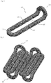
- FIG. 4 illustrates the coil structure of a slotless motor according to an embodiment of the present invention
- FIG. 5 illustrates the structure of the coil unit of a slotless motor according to an embodiment of the present invention
- FIG. 6 illustrates the structure of the coil unit of a slotless motor according to another embodiment of the present invention.
- a coil 100 for a slotless motor may be shaped as an elongated circle having one end portion 120 folded.
- the coil 100 can have the end portions of two parallel coil-sides 111, 112 connecting to a first end turn 121 and a second end turn 122, which have curved shapes, and the first end turn 121 can be formed in a folded shape to form a pre-configured angle with the two coil-sides 111, 112.
- the first end turn 121 and the two coil-sides 111, 112 can form a right angle.
- the bent portion at the first end turn 121 can be formed in a curved shape such as not to be caught when multiple coils 100 are placed overlapping one another.
- a space 130 can be formed between the two parallel coil-sides 111, 112 into which at least one coil-side may be placed. That is, the width between the two coil-sides 111, 112 can correspond to the width of one or two coil-sides 111, 112. For example, the width between the two coil-sides 111, 112 can be greater than the width of the coil-sides 111, 112.
- the coil 100 may be insulated, and the folded angle of the first end turn 121 with respect to the first end turn 121 and the second end turn 122 may not have a great impact.
- FIG. 5 shows a two-phase structure of a coil unit for a slotless motor according to an embodiment of the present invention.
- the coil unit of the slotless motor can be formed such that the first end turn 121 of the first coil 101 and the first end turn 121 of the second coil 102 face each other, where the first coil 101 and the second coil 102 may be overlapped in a manner such that the first coil-side 111 of the second coil 102 is inserted between the two coil-sides 111, 112 of the first coil 101.
- the bent portion of the folded first end turn 121 may be caught on a second end turn 122.
- the width between the two coil-sides 111, 112 can correspond to the width of one coil-side 111, 112 such that one coil-side can be placed between the two parallel coil-sides 111, 112.
- the winding of the slotless motor can be formed with the coil-sides 111, 112 of many coils 100 arranged alternatingly in an interlocking manner.
- FIG. 6 shows a three-phase structure of a coil unit for a slotless motor according to an embodiment of the present invention.
- the coil unit of the slotless motor can be formed such that the first end turn 121 of the third coil 103 and the first end turns 121 of the fourth coil 104 and fifth coil 105 face each other, where the third coil 103, fourth coil 104, and fifth coil 105 may be overlapped in a manner such that the second coil-side 112 of the fourth coil 104 and the first coil-side 111 of the fifth coil 105 are inserted between the two coil-sides 111, 112 of the third coil 103.
- the bent portion of the folded first end turn 121 may be caught on the second end turns 122.
- the width between the two coil-sides 111, 112 can correspond to the width of two coil-sides 111, 112 such that two coil-sides can be placed between the two parallel coil-sides 111, 112.
- the winding of the slotless motor can be formed with the coil-sides 111, 112 of many coils 100 arranged alternatingly in an interlocking manner.
Landscapes
- Engineering & Computer Science (AREA)
- Power Engineering (AREA)
- Windings For Motors And Generators (AREA)
- Manufacture Of Motors, Generators (AREA)
Abstract
Description
- This application is a National Phase Application of PCT International Application No.
PCT/KR2017/010229 10-2016-0119071 - The present invention relates to a slotless electric motor and a coil unit thereof.
- In a typical electric motor, the stator includes teeth that are formed by slots, which are the parts where the armature coils are wound, and iron cores, which serve as pathways for magnetic flux generated at the armature coils. Such a slotted structure maximizes permeance and thus provides a high air gap flux density, but the occurrence of a cogging torque is unavoidable.
- Also, the slotless structure, also referred to as the coreless structure, is a structure having no slots as the name implies and is characterized by creating a very uniform torque without a cogging torque. The slotless structure provides advantages in terms of noise and vibration, and since the amount of iron core used is greatly reduced, there is low iron loss, and the mechanical time constant is small, thereby allowing greater controllability.
- However, the armature winding of such slotless motor is of an air core structure and is not wound around iron cores, and as the coil has to be coupled to the stator using only the shape of the coil itself, the manufacturability may be lower compared to the core type electric motor.
-
FIG. 1 to FIG. 3 illustrate the coil structures of slotless motors according to the related art. - The coil structure of the slotless motor illustrated in
FIG. 1 is of a wound structure having the coils disposed in a roof tile arrangement. That is, in the coil structure ofFIG. 1 , the two coil-sides forming one turn are made to have different heights, so that several coils may be superimposed in a mutually interlocking arrangement. Thus, in the coil structure ofFIG. 1 , there are no changes in the air gaps when the windings are continued along the circumference of the stator, and as the coils interlock with one another, securing the coils is made easier, providing a benefit also in terms of manufacture. - However, the problems with the coil structure of
FIG. 1 are that: it is difficult to manufacture the coils to have different heights on either side, failure to produce the many coils in the same shape would cause difficulty also in lining the windings via interlocking coils, and differences in the shapes of the coils forming the respective phases can cause phase imbalance. - The coil structure illustrated in
FIG. 2 has several coils stacked, each separated by a particular distance along the circumference direction of the stator, where the parts at which the thickness of the coils is increased due to the coils being stacked one over the other and pressing against each other are compressed, so as to minimize the effective air gap length. - However, problem with the coil structure of
FIG. 2 is that it is difficult to manufacture the structure such that the coils are stacked in constant intervals. In particular, while the feature of the coil structure ofFIG. 2 is to minimize the air gap length by compressing the parts where the coils overlap, the effective air gap length is nevertheless increased compared to a non-overlapping state, and depending on the level of manufacturing technology, there is a high probability of the air gaps being nonuniform. - The coil structure illustrated in
FIG. 3 has the coils arranged facing each other, with both ends of a coil having a smaller horizontal width placed in an overlapping manner within the two ends of a coil having a larger horizontal width. - In the coil structure of
FIG. 3 also, the effective air gap length is different at the parts where the coils overlap, possibly causing a difference in inductance between the coils, and moreover, individually arranging and securing the several coils to face each other can be a cumbersome process. - An aspect of the present invention is to provide a slotless electric motor, and a coil unit of the slotless motor, where the coil unit has the same effective air gap length at any given point, there is no risk of lowered output caused by an increase in effective air gap length, there is reduced risk of phase imbalance, and the coil unit has a very simple structure to also provide an advantage in terms of manufacture.
- One aspect of the present invention discloses a coil unit for a slotless motor having a two-phase structure.
- In a coil unit of a slotless electric motor according to an embodiment of the present invention, a first coil and a second coil may be formed overlapping each other such that a first end turn of the first coil and a first end turn of the second coil face each other and a first coil-side of the second coil is inserted between the two coil-sides of the first coil, and the first coil and second coil may be formed such that the end portions of the two coil-sides connect to the first end turn and the second end turn having curved shapes, with the first end turn folded to form a pre-configured angle with respect to the two coil-sides.
- The first end turn and the two coil-sides may form a right angle.
- The bent portion of the first end turn may be formed in a curved shape such as not to be caught when multiple coils are overlapped over one another and may be caught on the second end turn.
- The first coil and the second coil may be formed such that the width between the two coil-sides corresponds to the width of one coil-side, so that a coil-side may be inserted between the two coil-sides.
- Another aspect of the present invention discloses a coil unit for a slotless motor having a three-phase structure.
- In a coil unit of a slotless electric motor according to an embodiment of the present invention, a first coil, a second coil, and a third coil may be formed overlapping one another such that a first end turn of the first coil and the first end turns of the second coil and the third coil face each other and a second coil-side of the second coil and a first coil-side of the third coil are inserted between the two coil-sides of the first coil, and the first coil, the second coil, and the third coil may be formed such that the end portions of the two coil-sides connect to the first end turn and the second end turn having curved shapes, with the first end turn folded to form a pre-configured angle with respect to the two coil-sides.
- The first coil, the second coil, and the third coil may be formed such that the width between the two coil-sides corresponds to the width of two coil-sides, so that two coil-sides may be inserted between the two coil-sides.
- With a slotless motor and a coil unit of a slotless motor according to an embodiment of the present invention, the effective air gap length can be made the same at any given point, the risk of lowered output due to an increase in effective air gap length can be eliminated, the risk of phase imbalance can be reduced, and the structure can be greatly simplified to also provide an advantage in terms of manufacture.
-
-
FIG. 1, FIG. 2, and FIG. 3 illustrate the coil structures of slotless motors according to the related art. -
FIG. 4 illustrates the coil structure of a slotless motor according to an embodiment of the present invention. -
FIG. 5 illustrates the structure of the coil unit of a slotless motor according to an embodiment of the present invention. -
FIG. 6 illustrates the structure of the coil unit of a slotless motor according to another embodiment of the present invention. - In the present specification, an expression used in the singular encompasses the expression of the plural, unless it has a clearly different meaning in the context. In the present specification, terms such as "comprising" or "including," etc., should not be interpreted as meaning that all of the components or steps are necessarily included. That is, some of the components or steps may not be included, while other additional components or steps may be further included. Also, terms such as "part", "module", etc., used in the present specification refer to a unit that processes at least one function or operation, where such a unit can be implemented as hardware or software or as a combination of hardware and software.
- Various embodiments of the invention will be described below in more detail with reference to the accompanying drawings.
-
FIG. 4 illustrates the coil structure of a slotless motor according to an embodiment of the present invention,FIG. 5 illustrates the structure of the coil unit of a slotless motor according to an embodiment of the present invention, andFIG. 6 illustrates the structure of the coil unit of a slotless motor according to another embodiment of the present invention. - Referring to
FIG. 4 , acoil 100 for a slotless motor according to an embodiment of the present invention may be shaped as an elongated circle having one end portion 120 folded. - That is, as illustrated in
FIG. 4 , thecoil 100 can have the end portions of two parallel coil-sides first end turn 121 and asecond end turn 122, which have curved shapes, and thefirst end turn 121 can be formed in a folded shape to form a pre-configured angle with the two coil-sides sides first end turn 121 can be formed in a curved shape such as not to be caught whenmultiple coils 100 are placed overlapping one another. - Here, a
space 130 can be formed between the two parallel coil-sides sides sides sides sides - The
coil 100 may be insulated, and the folded angle of the first end turn 121 with respect to thefirst end turn 121 and thesecond end turn 122 may not have a great impact. - Referring to
FIG. 5, FIG. 5 shows a two-phase structure of a coil unit for a slotless motor according to an embodiment of the present invention. - As illustrated in
FIG. 5 , the coil unit of the slotless motor can be formed such that thefirst end turn 121 of thefirst coil 101 and thefirst end turn 121 of thesecond coil 102 face each other, where thefirst coil 101 and thesecond coil 102 may be overlapped in a manner such that the first coil-side 111 of thesecond coil 102 is inserted between the two coil-sides first coil 101. Here, the bent portion of the foldedfirst end turn 121 may be caught on asecond end turn 122. - In the
coils FIG. 5 , the width between the two coil-sides side sides - In this way, the winding of the slotless motor can be formed with the coil-
sides many coils 100 arranged alternatingly in an interlocking manner. - Referring to
FIG. 6, FIG. 6 shows a three-phase structure of a coil unit for a slotless motor according to an embodiment of the present invention. - As illustrated in
FIG. 6 , the coil unit of the slotless motor can be formed such that thefirst end turn 121 of thethird coil 103 and the first end turns 121 of thefourth coil 104 andfifth coil 105 face each other, where thethird coil 103,fourth coil 104, andfifth coil 105 may be overlapped in a manner such that the second coil-side 112 of thefourth coil 104 and the first coil-side 111 of thefifth coil 105 are inserted between the two coil-sides third coil 103. Here, the bent portion of the foldedfirst end turn 121 may be caught on the second end turns 122. - In the
coils FIG. 6 , the width between the two coil-sides sides sides - In this way, the winding of the slotless motor can be formed with the coil-
sides many coils 100 arranged alternatingly in an interlocking manner. - The embodiments of the present invention set forth above are disclosed only for illustrative purposes. The person having ordinary skill in the art familiar with the present invention would be able to make various modifications, alterations, and additions without departing from the spirit and scope of the present invention, and such modifications, alterations, and additions are to be regarded as being encompassed by the scope of claims set forth below.
Claims (7)
- A coil unit of a slotless electric motor having a two-phase structure, wherein a first coil and a second coil are formed overlapping each other such that a first end turn of the first coil and a first end turn of the second coil face each other and a first coil-side of the second coil is inserted between two coil-sides of the first coil,
and the first coil and second coil are formed such that end portions of the two coil-sides connect to the first end turn and the second end turn, the first end turn and the second end turn having curved shapes, the first end turn folded to form a pre-configured angle with respect to the two coil-sides. - The coil unit of a slotless electric motor according to claim 1, wherein the first end turn and the two coil-sides form a right angle.
- The coil unit of a slotless electric motor according to claim 1, wherein a bent portion of the first end turn is formed in a curved shape such as not to be caught when a plurality of coils are overlapped over one another and is caught on the second end turn.
- The coil unit of a slotless electric motor according to claim 1, wherein the first coil and the second coil are formed with a width between the two coil-sides corresponding to a width of one coil-side to enable a coil-side to be inserted between the two coil-sides.
- A coil unit of a slotless electric motor having a three-phase structure, wherein a first coil, a second coil, and a third coil are formed overlapping one another such that a first end turn of the first coil and first end turns of the second coil and the third coil face each other and a second coil-side of the second coil and a first coil-side of the third coil are inserted between two coil-sides of the first coil,
and the first coil, the second coil, and the third coil are formed such that end portions of the two coil-sides connect to the first end turn and the second end turn, the first end turn and the second end turn having curved shapes, the first end turn folded to form a pre-configured angle with respect to the two coil-sides. - The coil unit of a slotless electric motor according to claim 5, wherein the first coil, the second coil, and the third coil are formed with a width between the two coil-sides corresponding to a width of two coil-sides to enable two coil-sides to be inserted between the two coil-sides.
- A slotless motor comprising a coil unit according to any one of claim 1 to claim 6.
Applications Claiming Priority (2)
| Application Number | Priority Date | Filing Date | Title |
|---|---|---|---|
| KR1020160119071A KR101769717B1 (en) | 2016-09-19 | 2016-09-19 | Slotless motor and coil structure of the same |
| PCT/KR2017/010229 WO2018052268A1 (en) | 2016-09-19 | 2017-09-19 | Slotless electric motor and coil unit thereof |
Publications (2)
| Publication Number | Publication Date |
|---|---|
| EP3518393A1 true EP3518393A1 (en) | 2019-07-31 |
| EP3518393A4 EP3518393A4 (en) | 2020-05-06 |
Family
ID=59757602
Family Applications (1)
| Application Number | Title | Priority Date | Filing Date |
|---|---|---|---|
| EP17851142.4A Withdrawn EP3518393A4 (en) | 2016-09-19 | 2017-09-19 | SLOTLESS ELECTRIC MOTOR AND COIL UNIT THEREFOR |
Country Status (5)
| Country | Link |
|---|---|
| US (1) | US10992202B2 (en) |
| EP (1) | EP3518393A4 (en) |
| KR (1) | KR101769717B1 (en) |
| CN (1) | CN109716627A (en) |
| WO (1) | WO2018052268A1 (en) |
Families Citing this family (12)
| Publication number | Priority date | Publication date | Assignee | Title |
|---|---|---|---|---|
| US11075556B2 (en) * | 2017-01-30 | 2021-07-27 | Kesatoshi Takeuchi | Coreless electric machine with magnet coils with effective coil part and end coil parts |
| JP7147628B2 (en) * | 2019-02-25 | 2022-10-05 | 株式会社デンソー | Armature and rotating electric machine |
| KR102233003B1 (en) * | 2019-03-12 | 2021-03-26 | 한양대학교 산학협력단 | Coil assembly of slotless motor, housing and slotless motor including the same |
| TWI779315B (en) * | 2020-07-13 | 2022-10-01 | 東佑達自動化科技股份有限公司 | Ironless linear motor and its coil device |
| EP4160876B1 (en) * | 2021-10-04 | 2025-04-30 | Hamilton Sundstrand Corporation | Windings for electrical machines |
| US11677303B2 (en) * | 2021-10-21 | 2023-06-13 | National Cheng Kung University | Motor and coreless stator coil winding unit thereof |
| KR102717767B1 (en) * | 2023-06-22 | 2024-10-16 | 한국전력공사 | A method of manufacturing a block coil for slotless winding arrangement and an assembly accordingly |
| KR102930273B1 (en) | 2023-08-04 | 2026-02-24 | 한양대학교 산학협력단 | Stator of axial slotless motor |
| KR20250067524A (en) | 2023-11-08 | 2025-05-15 | 현대위아 주식회사 | Assembly Coil for slotless motor |
| KR20250067523A (en) | 2023-11-08 | 2025-05-15 | 현대위아 주식회사 | Assembly Coil for slotless motor |
| KR20250070457A (en) | 2023-11-13 | 2025-05-20 | 현대위아 주식회사 | Assembly Coil for slotless motor |
| KR102930281B1 (en) * | 2024-05-21 | 2026-02-23 | 한양대학교 산학협력단 | Stator of linear slotless motor |
Family Cites Families (20)
| Publication number | Priority date | Publication date | Assignee | Title |
|---|---|---|---|---|
| JPH076705Y2 (en) | 1992-01-10 | 1995-02-15 | 三菱電機株式会社 | Movable element of polyphase type linear motor |
| US5731645A (en) * | 1996-02-05 | 1998-03-24 | Magnetic Bearing Technologies, Inc. | Integrated motor/generator/flywheel utilizing a solid steel rotor |
| US5744896A (en) * | 1996-05-21 | 1998-04-28 | Visual Computing Systems Corp. | Interlocking segmented coil array |
| US6590355B1 (en) * | 1999-06-07 | 2003-07-08 | Nikon Corporation | Linear motor device, stage device, and exposure apparatus |
| JP3484152B2 (en) * | 2000-09-12 | 2004-01-06 | 住友重機械工業株式会社 | Two-phase excitation type linear motor |
| JP2004516649A (en) * | 2000-12-11 | 2004-06-03 | コーニンクレッカ フィリップス エレクトロニクス エヌ ヴィ | Band coil |
| US6806594B2 (en) * | 2002-02-20 | 2004-10-19 | Sumitomo Heavy Industries, Ltd. | Coil unit for linear motor |
| KR100463495B1 (en) | 2002-07-05 | 2004-12-29 | 삼익Lms주식회사 | Linear motor with cooling control system |
| JP2004343952A (en) * | 2003-05-19 | 2004-12-02 | Asaba:Kk | Dc motor |
| US20050006977A1 (en) * | 2003-05-21 | 2005-01-13 | Raffaele Becherucci | Apparatus and methods for winding dynamo-electric machine components |
| KR100541113B1 (en) * | 2004-07-01 | 2006-01-11 | 삼성전기주식회사 | Pattern Coil Type Vertical Oscillator |
| NZ577290A (en) | 2006-12-28 | 2011-11-25 | Resmed Motor Technologies Inc | Making a winding for a slotless stator by collapsing coil groups into a single layer web with interleaving coil segments |
| KR100804810B1 (en) | 2006-12-29 | 2008-02-20 | 주식회사 효성 | Stator for slotless motor |
| KR101053921B1 (en) | 2008-12-24 | 2011-08-04 | 전자부품연구원 | Coil stack and slotless motor having same |
| EP2226923B1 (en) * | 2009-03-03 | 2015-06-10 | GE Energy Power Conversion Technology Limited | Coils |
| CN101982930B (en) * | 2010-11-10 | 2012-07-11 | 哈尔滨工业大学 | Efficient three-phase slot-free permanent magnet motor |
| JP2012253922A (en) * | 2011-06-03 | 2012-12-20 | Seiko Epson Corp | Coreless electromechanical device, mobile object, robot, and coreless-electromechanical-device producing method |
| JP2013058658A (en) * | 2011-09-09 | 2013-03-28 | Seiko Epson Corp | Electromagnetic coil, coreless electric machine device, moving body, robot, and manufacturing method of electromagnetic coil |
| JP2013078167A (en) * | 2011-09-29 | 2013-04-25 | Seiko Epson Corp | Coreless electromechanical device, moving body, robot and manufacturing method of coreless electromechanical device |
| US9148047B2 (en) * | 2012-11-30 | 2015-09-29 | Chieftek Precision Co., Ltd. | Coil assembly having separation plates for iron less linear motor |
-
2016
- 2016-09-19 KR KR1020160119071A patent/KR101769717B1/en active Active
-
2017
- 2017-09-19 WO PCT/KR2017/010229 patent/WO2018052268A1/en not_active Ceased
- 2017-09-19 EP EP17851142.4A patent/EP3518393A4/en not_active Withdrawn
- 2017-09-19 US US16/332,237 patent/US10992202B2/en active Active
- 2017-09-19 CN CN201780055619.4A patent/CN109716627A/en active Pending
Also Published As
| Publication number | Publication date |
|---|---|
| EP3518393A4 (en) | 2020-05-06 |
| CN109716627A (en) | 2019-05-03 |
| WO2018052268A1 (en) | 2018-03-22 |
| US10992202B2 (en) | 2021-04-27 |
| US20190273409A1 (en) | 2019-09-05 |
| KR101769717B1 (en) | 2017-08-21 |
Similar Documents
| Publication | Publication Date | Title |
|---|---|---|
| US10992202B2 (en) | Slotless electric motor and coil unit thereof | |
| TWI524633B (en) | Rotating electric machine and manufacturing method of rotating electric machine | |
| US8610328B2 (en) | Rotary electric machine | |
| EP2909922B1 (en) | Stator of rotary electric machine | |
| US20040021391A1 (en) | Nested stator coils for permanent magnet machines | |
| CN100550576C (en) | Motor and manufacture method thereof | |
| US10199887B2 (en) | Rotary electric machine armature core and rotary electric machine | |
| US9385568B2 (en) | Stator and electric motor having the same | |
| CN104426315A (en) | Three-phase electromagnetic motor | |
| US20220263356A1 (en) | Motor | |
| US12068652B2 (en) | Coil assembly of slotless motor, housing and slotless motor including the same | |
| US10608493B2 (en) | Stator for rotary electric machine having distributed winding structure | |
| JP5502533B2 (en) | Permanent magnet type motor | |
| JP6598736B2 (en) | Rotating electric machine stator | |
| CN107005112A (en) | Electric rotating machine | |
| JP2012170295A (en) | Stator of rotary electric machine and method of manufacturing the same | |
| JP5042253B2 (en) | Armature of rotating electric machine and method for manufacturing the same | |
| KR100396786B1 (en) | Stator structure for reciprocating compressor | |
| EP3687042A1 (en) | Insulator, and stator and motor comprising same | |
| US20220294283A1 (en) | Coil, stator, motor, and manufacturing method of stator | |
| KR102339538B1 (en) | Stator and motor having the same | |
| JP2015019452A (en) | Coil and coil forming method | |
| JP6654551B2 (en) | Electric motor | |
| KR20110118244A (en) | Stator for motor and motor with same | |
| JP6900790B2 (en) | Rotating machine |
Legal Events
| Date | Code | Title | Description |
|---|---|---|---|
| STAA | Information on the status of an ep patent application or granted ep patent |
Free format text: STATUS: THE INTERNATIONAL PUBLICATION HAS BEEN MADE |
|
| PUAI | Public reference made under article 153(3) epc to a published international application that has entered the european phase |
Free format text: ORIGINAL CODE: 0009012 |
|
| STAA | Information on the status of an ep patent application or granted ep patent |
Free format text: STATUS: REQUEST FOR EXAMINATION WAS MADE |
|
| 17P | Request for examination filed |
Effective date: 20190305 |
|
| AK | Designated contracting states |
Kind code of ref document: A1 Designated state(s): AL AT BE BG CH CY CZ DE DK EE ES FI FR GB GR HR HU IE IS IT LI LT LU LV MC MK MT NL NO PL PT RO RS SE SI SK SM TR |
|
| AX | Request for extension of the european patent |
Extension state: BA ME |
|
| DAV | Request for validation of the european patent (deleted) | ||
| DAX | Request for extension of the european patent (deleted) | ||
| A4 | Supplementary search report drawn up and despatched |
Effective date: 20200402 |
|
| RIC1 | Information provided on ipc code assigned before grant |
Ipc: H02K 3/28 20060101ALI20200328BHEP Ipc: H02K 3/47 20060101AFI20200328BHEP |
|
| STAA | Information on the status of an ep patent application or granted ep patent |
Free format text: STATUS: EXAMINATION IS IN PROGRESS |
|
| 17Q | First examination report despatched |
Effective date: 20210315 |
|
| STAA | Information on the status of an ep patent application or granted ep patent |
Free format text: STATUS: THE APPLICATION IS DEEMED TO BE WITHDRAWN |
|
| 18D | Application deemed to be withdrawn |
Effective date: 20210928 |