CN101573859B - Coil winding methods and structures for a slotless stator in a motor - Google Patents
Coil winding methods and structures for a slotless stator in a motor Download PDFInfo
- Publication number
- CN101573859B CN101573859B CN2007800484169A CN200780048416A CN101573859B CN 101573859 B CN101573859 B CN 101573859B CN 2007800484169 A CN2007800484169 A CN 2007800484169A CN 200780048416 A CN200780048416 A CN 200780048416A CN 101573859 B CN101573859 B CN 101573859B
- Authority
- CN
- China
- Prior art keywords
- coil
- winding
- groups
- coil groups
- axle
- Prior art date
- Legal status (The legal status is an assumption and is not a legal conclusion. Google has not performed a legal analysis and makes no representation as to the accuracy of the status listed.)
- Active
Links
Images


Classifications
-
- H—ELECTRICITY
- H02—GENERATION; CONVERSION OR DISTRIBUTION OF ELECTRIC POWER
- H02K—DYNAMO-ELECTRIC MACHINES
- H02K15/00—Methods or apparatus specially adapted for manufacturing, assembling, maintaining or repairing of dynamo-electric machines
- H02K15/06—Embedding prefabricated windings in machines
-
- H—ELECTRICITY
- H02—GENERATION; CONVERSION OR DISTRIBUTION OF ELECTRIC POWER
- H02K—DYNAMO-ELECTRIC MACHINES
- H02K3/00—Details of windings
- H02K3/04—Windings characterised by the conductor shape, form or construction, e.g. with bar conductors
- H02K3/28—Layout of windings or of connections between windings
-
- H—ELECTRICITY
- H02—GENERATION; CONVERSION OR DISTRIBUTION OF ELECTRIC POWER
- H02K—DYNAMO-ELECTRIC MACHINES
- H02K15/00—Methods or apparatus specially adapted for manufacturing, assembling, maintaining or repairing of dynamo-electric machines
- H02K15/04—Methods or apparatus specially adapted for manufacturing, assembling, maintaining or repairing of dynamo-electric machines of windings, prior to mounting into machines
- H02K15/0435—Wound windings
- H02K15/0442—Loop windings
-
- H—ELECTRICITY
- H02—GENERATION; CONVERSION OR DISTRIBUTION OF ELECTRIC POWER
- H02K—DYNAMO-ELECTRIC MACHINES
- H02K15/00—Methods or apparatus specially adapted for manufacturing, assembling, maintaining or repairing of dynamo-electric machines
- H02K15/04—Methods or apparatus specially adapted for manufacturing, assembling, maintaining or repairing of dynamo-electric machines of windings, prior to mounting into machines
- H02K15/0435—Wound windings
- H02K15/0464—Lap windings
- H02K15/0471—Lap windings manufactured by flattening a spiral winding
-
- Y—GENERAL TAGGING OF NEW TECHNOLOGICAL DEVELOPMENTS; GENERAL TAGGING OF CROSS-SECTIONAL TECHNOLOGIES SPANNING OVER SEVERAL SECTIONS OF THE IPC; TECHNICAL SUBJECTS COVERED BY FORMER USPC CROSS-REFERENCE ART COLLECTIONS [XRACs] AND DIGESTS
- Y10—TECHNICAL SUBJECTS COVERED BY FORMER USPC
- Y10T—TECHNICAL SUBJECTS COVERED BY FORMER US CLASSIFICATION
- Y10T29/00—Metal working
- Y10T29/49—Method of mechanical manufacture
- Y10T29/49002—Electrical device making
- Y10T29/49009—Dynamoelectric machine
Abstract
A method to form a field winding for a slotless stator including: forming the first coil group by spirally winding an insulated wire for each coil winding around a mandrel such that each turn of the wire is adjacent a next turn of the wire; after forming the first coil group, axially shifting along the mandrel the insulated wire from a trailing edge of each coil winding to position the wires at a leading edge of each of coil winding in the second coil group; forming the second coil group by spirally winding the insulated wire for each coil winding around a mandrel; removing the mandrel from the wound first and second coil groups; collapsing the wound coil groups to a layer web such that coil winding segments are interleaved; and wrapping the web into a cylinder to form the field winding.
Description
Cross reference in first to file
It is the interests of 60/877,373 U.S. Provisional Application that the application requires in the application number that on December 28th, 2006 submitted to, and its full content is incorporated herein by reference.
Technical field
The present invention relates to the stator of power motor.The invention particularly relates to the method for multi-phase excitation winding that is formed for exchanging the non-groove stator of (AC) and direct current (DC) motor by a plurality of coil windings, and for the coil windings layout of this stator.
Background technology
Motor has usually around the annular stator of cylindrical inner rotor and the air gap between stator and rotor.Stator typically comprises the excitation winding that is formed by the conductive coil winding.Heterogeneous, for example in the excitation winding of threephase motor a plurality of coil windings are arranged.Each coil windings by insulated conductor for example electric wire form, described wire extends back and forth along the length of stator.Alternating current by coil windings produces rotary electromagnetic field in the hollow part of cylindrical stator.Rotor in stator rotates by rotating field.
The stator coil winding forms usually through the following steps: around axle (mandrel) twine electric wire for example conductive coil, axle is removed from the coil that twines, the coil that twines is folded into reel (web) and reel is wound into cylinder to be included in the stator.The known layout and the method that are used for the winding around winding are disclosed in following patent: the 3rd, 813, No. 267, the 5th, 197, No. 180, the 5th, 425, No. 165, the 5th, 619, No. 085, the 5th, 714, No. 827, the 6th, 355, No. 993 and the 6th, 791, No. 224 United States Patent (USP)s.Need for a long time non-groove stator coil layout and winding method relatively easy, that implement cheaply and provide effective excitation winding of stator.
Summary of the invention
Developed be used for winding around with the new coil windings layout that forms excitation winding and method to be used for the non-groove stator at multiphase motor.Coil windings is installed on the inner surface of magnetic flux winding (fluxreturn ring), and the endless belt (annulus) of the coaxial son that rotates of formation and stator and winding.Be applied to electric power on the coil windings of stator according to the electrodynamic power that applies with certain speed and torque drive rotor.Electric power typically is polyphase ac (AC) voltage, such as three-phase AC voltage.The stator excitation winding comprises the absolute coil winding for every phase of AC voltage.
The layout of coil windings disclosed herein also is applicable to the stator as generator.Winding method is formed for for example a plurality of coil windings of the heterogeneous non-groove stator of three-phase, for example three (A, B, C).The stator coil winding can be used in the small size motor of the air blast in the sleep apnea therapeutic system.
A kind of manufacturing disclosed herein is used for the method such as the multi-phase excitation winding of three phase excitation winding of non-groove stator, described multi-phase excitation winding comprises a plurality of coil windings that are arranged in the first coil groups and the second coil groups, described method comprises: form the first coil groups by the insulated electric conductor that twines each coil windings around axle so that every circle of electric wire is close to next circle of electric wire, wherein each coil windings in the first coil groups has essentially identical coil width when finishing, and the distance of one width in the winding that is substantially equal to finish of being spaced apart between the coil windings of the vicinity in the first coil groups; After forming the first coil groups, the certain head end (leading edge) of distance electric wire is positioned at each coil windings in the second coil groups of mobile insulated electric conductor axially from the tail end (trailing edge) of each coil windings along axle, five times of one width in the winding that described distance is substantially equal to finish; So that being close to next circle of electric wire, every circle of electric wire forms the second coil groups by the insulated electric conductor that twines each coil windings around axle, wherein each coil windings in the second coil groups and the first coil groups has substantially the same coil width when finishing, and wherein the winding direction of the second coil groups is identical or opposite with the winding direction of the first coil groups, and the distance of one width in the winding that is substantially equal to finish of being spaced apart between the coil windings of the vicinity in the first coil groups; Axle is removed from first and second coil groups of twining; The first coil groups and second coil groups of twining are folded into single layer web so that coming from the coil winding segments (segment) of the first coil groups intersects between the coil winding segments of the second coil groups, and single layer web is wound into cylinder to form excitation winding.
Disclose a kind of multi-phase excitation winding such as the three phase excitation winding for non-groove stator, having comprised: a plurality of coil windings, it comprises the first coil groups and the second coil groups; The first coil groups, it comprises the first spiral winding for the insulated electric conductor of each coil windings, and wherein electric wire twines so that next circle of the contiguous electric wire of every circle of electric wire and the width that the gap between the coil windings of the vicinity on the axle in the first coil groups is substantially equal to the coil windings in first group around axle; The second coil groups, it comprises the second spiral winding of the insulated electric conductor of each coil windings, wherein electric wire twines so that next circle of the contiguous electric wire of every circle of electric wire around axle, wherein each coil windings in the second coil groups and the first coil groups has essentially identical coil width when finishing, be substantially equal to the width of the coil windings in second group in the second coil groups in the gap between the coil windings of the vicinity on the axle, and the winding direction of the second coil groups is opposite with the first coil groups; And columnar reel, it comprises the first coil groups and the second coil groups, described the first coil groups and the second coil groups are folded into so that the coil winding segments of the first coil groups intersects between the coil winding segments of the second coil groups.
A kind of manufacturing is disclosed for the method for the three phase excitation winding that is used for non-groove stator that comprises three coil windings, described method comprises: the insulated electric conductor by twining each coil windings around axle is so that next circle of the contiguous electric wire of every circle of electric wire forms the coil groups of three coil windings, wherein each coil windings in the first coil groups has essentially identical coil width when finishing, and the distance of one width in the winding that is substantially equal to finish of being spaced apart between the coil windings of the vicinity in the first coil groups; Axle is removed from the coil groups of twining; Folding coil groups of twining is so that come from the coil winding segments of the first side of axle and intersect between the coil winding segments of the opposition side that comes from axle, and single layer web is wound into cylinder to form excitation winding, wherein intersect between the coil winding segments at end opposite place of reel in the coil winding segments of an end of reel, and the winding segments that comes from identical coil windings is on the opposition side of cylinder.
A kind of method of the magnetic field for twining the heterogeneous equipment of electromagnetism is disclosed, comprise: twine spirally a plurality of insulated conductors to form first group of coil windings around axle, wherein at least one in other winding arounds in axle is close to first group of the winding around in first group; The length of wire is axially moved certain distance along axle, and described distance is substantially equal to the width of the winding around in first group; Begin in the distance of width that is substantially equal to first group winding around apart from the tail end of first group of coil windings, twine spirally second group of coil with the winding direction identical with the winding direction that uses in first group, at least one in other winding arounds among first group of the axle next-door neighbour of the winding around that wherein in second group, forms; Axle is removed and coil is flattened to form single layer web, single layer web comprises first group the coil segment that intersects with second group coil segment, and reel is wound into two-layer cylinder, and wherein first group coil is overlapping with the coil in second group that is formed by identical wire.
Description of drawings
Fig. 1 is three coil windings are wound as the first structure of two coil groups in axle schematic diagram.
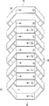
Fig. 2 is the schematic diagram of coil in the situation that axle is removed and coil windings is folded into single layer web shown in Figure 1.
Fig. 3 is the schematic cross section of end-view that is arranged on the reel of the coil shown in Figure 2 in the individual layer cylindrical spool.
Fig. 4 is the schematic diagram that is installed in the magnetic flux winding with the end-view of the cylindrical spool shown in Figure 2 that forms stator.
Fig. 5 is the schematic diagram that is illustrated in the electric power three-phase coil structure of the First Line coil winding structure shown in Fig. 1 to Fig. 4.
Fig. 6 has the unicoil group for each and the schematic diagram of the second structure of three coil windings of reeling around axle.
Fig. 7 is the schematic diagram of the second structure of the coil windings in the situation that axle is removed and coil is folded into single layer web.
Fig. 8 is the schematic cross section of end-view of reel that comes from Fig. 7 and form the coil windings of drum.
Fig. 9 is the schematic cross section of end-view that is installed in the solenoid coil reel of the Fig. 8 in the magnetic flux winding.
Figure 10 is the schematic diagram of the electric power three-phase coil structure of expression the second coil winding arrangement.
Figure 11 is three coil windings are wound as two coil groups in axle the 3rd structure.
Figure 12 is the schematic diagram of the 3rd structure of the coil windings in the situation that axle is removed and coil is folded into double drum.
Figure 13 is the schematic cross section of end-view of reel that is arranged on the coil windings of the Figure 12 in the double-layered cylinder.
Figure 14 is the schematic cross section of end-view that is installed in the two-double cylinder coil windings reel of Figure 13 in the magnetic flux winding.
Figure 15 is the schematic diagram of the electric power three-phase coil structure of expression tertiary coil winding construction.
Figure 16 is the schematic cross section of end-view of reel that is arranged on the coil windings of the Figure 12 in the individual layer cylinder.
Figure 17 is the cross-sectional view of end-view that is installed in the single-layer solenoid winding reel of the Figure 16 in the magnetic flux winding.
Figure 18 is three coil windings are wound as the 4th structure of two coil groups in axle schematic diagram.
Figure 19 is the schematic diagram of the coil shown in the Figure 18 in the situation that axle is removed and coil windings is folded into single layer web.
Figure 20 is the schematic cross section of end-view that is arranged on the reel of the coil shown in Figure 19 in the magnetic flux winding.
Figure 21 is the schematic diagram that is installed in the magnetic flux winding with the end-view of the solenoid coil reel shown in Figure 2 that forms stator.
Embodiment
Fig. 1 is three coil windings (A, B, C) are wound as the first structure 10 of two coil groups 12,14 (A1, B1 and C1, and A2, B2 and C2) in axle 16 schematic diagram.Insulated conductive wire coils to form the group of each coil windings around axle.Many adhesive tape 18 is attached to the opposition side of coil groups so that coil is temporarily kept together.After axle is removed and when structure 10 is folded into reel (seeing Fig. 2), adhesive tape helps the distance between the hold-in winding and between the coil groups.
The track type cross section of axle 16 has substantially upright relative wall part 20 and top side and the bottom side 22 of ridge is arranged.Axle preferably has hexagonal transverse cross section, but also can have other polygon cross section, perhaps has two relative wall parts 20 and crooked top side and bottom side 22.
The wall part 20 of axle often has common length and longer than top side and bottom side.Wall part 20 is used for forming the vertical section 24,26 (seeing Fig. 2) of coil windings, and described vertical section 24,26 is arranged in the cylinder and in the face of the rotor in the motor.Wall part 20 has the width that substantially equates with the length of stator coil section to be formed.
The coiler part that is positioned at the top side of axle and bottom side 22 forms end turn part (the end turn section) 28 of coil windings.The width of axle, that is, the distance between the wall part 20 has been determined the width of the end turn part 28 of coil relatively.When coil was flattened into reel, end turn must have the coil groups that is enough to across connecting, for example length in the gap between A1 and the A2.Therefore, the width of axle must be enough to so that end turn has the length of their needs.
When forming stator, coil segment 24,26 is arranged in the cylinder of stator.Coil segment is parallel and adjacent rotor.Coil segment is arranged on the inner cylindrical surface of stator, separates by annulus gap and rotor, and extends the length of rotor.The end turn part 28 of coil connects contiguous straight coil segments 24,26.End turn part 28 is folding or arrange compactly.In typical coil windings, straight coil segments 24,26 and end turn part 28 will be with continuous electric lead with insulating sleeve alternately.The width of end turn part, for example the distance between the relative wall part 20 is enough to allow end turn across the distance between the coil groups that connects in the situation about folding at coil.
Each coil groups 12,14 is by becoming wire intertwist tight spirality to form, and wherein in each coil windings, every circle of electric wire is close to next circle.The end that the initial turns of each winding (start turn) is located is represented by SA, SB and SC respectively.The end that the last circle of each coil windings (last turn) is located is represented by EA, EB and EC respectively.The automatic winding mechanism that is known in the art can be used for around axle wound wire automatically.The electric wire of each winding at first twines to form coil first group 12 at first direction (winding direction indicated by the arrow).The first coil groups comprises the number of turns of wire of scheduled volume, for example, and 25 to 250 circles.Typically, the wire turn surface of pasting axle is bundled into parallel organization together tightly to form the winding around of individual layer.
Independently electric wire is used to form each coil windings.As shown in Figure 1, three eradication edge electric wires (A, B, C) twine around axle.Electric wire twines to form coil first group 12 at first direction at first.Each coil groups (A1, B1, C1) is corresponding to the independently insulated electric conductor that twines around axle.Each coil groups has essentially identical winding quantity so that the number of turn in the width of each coil groups and each coil groups is basic identical.
Interval between the contiguous coil groups, for example, the gap (G) between the head end of the tail end of coil groups A1 and coil groups B1 can be the width (w) of coil segment.(see Fig. 2) when coil is flattened into single layer web, this gap allows coil segment not having to place the gap in the situation of overlapped stitches.
After the winding of first group of coil windings (A1, B1, C1) and before next group coil windings (A2, B2, C2) is twined, axially mobile from each coil groups of finishing 12 extended electric lead along axle.Move axially and make first coil groups of electric lead from finishing, for example the tail end of A1 moves to for example head end of A2 of the second coil groups to be wound.For the three-phase coil with two coil groups, axially movable distance be coil winding segments width (w) five (5) doubly.For having polyphase winding winding except three-phase and the polyphase winding winding of different coil groups numbers, it is different moving axially.In general, move axially the quantity that multiply by coil windings for the twice of the quantity of coil groups from the coil groups 12 finished to new coil groups 14, deduct 1.This moves axially algorithm and will be used on the axle coil windings that can be folded into lamina.
The electric lead of each coil (A, B, C) at first in one direction, for example twine to form the first coil groups (A1, B1 and C1) on the clockwise direction, and afterwards in another opposite direction, for example counterclockwise upper winding is to form the second coil groups (A2, B2, C2).Winding direction is represented by arrow in the drawings.Additional coil groups can by around axle clockwise and counterclockwise alternately winding around form.Repeat the winding around group until form the quantity of the coil groups that needs by putting upside down winding direction.
After finishing winding, axle is removed from the coil that twines.When axle is removed, the position of adhesive tape 18 hold-in winding groups so that electric wire keeps parallel in their coil groups separately and coil groups between keep the gap.Adhesive tape typically is two bands on each coil segment 24,26 opposition side.Article one, adhesive tape is fixed on the surface of axle, and adhesive surface is outwardly to accept winding around simultaneously.The second adhesive tape is attached on the coil segment and typically is used for being pressed in article one adhesive tape after finishing winding process.
Fig. 2 has shown the coil windings after axle removed.Coil is flattened into single layer web 30.Correctly overlapping in order to ensure coil segment, axially mobile such as the position in the gap between the section of C1 and A2 towards what select at the opposition side of coil in the section such as A1 ' on the first side of coil.Coil segment is arranged in the reel so that a plurality of sections (for example, A1, B1, C1, A1 ', A2, B1 ', B2, C1 ', C2, A2 ', B2 ' and C2 ') is parallel and can be not overlapping.Coil segment 24,26 (A1, B1, C1, A1 ', B1 ' and C1 ') is the part of the stationary part that will form adjacent rotor of reel.Coil segment 24,26 will be arranged in the stator so that they are parallel to the rotating shaft of rotor.
Depend on described section winding direction by the sense of current of coil segment.The location comes from the coil segment of identical coil and has guaranteed that the sense of current by adjacent segment is identical so that adjacent segment has identical winding direction.
The coil segment (A1, B1 and B2 ' and C2 ') of close reel ends is spaced from each other by gap (G).These gaps will hold the coil segment of the end opposite that comes from reel.Especially, when reel is rolled into cylinder, section A1 will the section of being installed in A2 ' and B2 ' between the gap in, and section B1 will the section of being installed in B2 ' and C2 ' between the gap in.
Fig. 3 is the cross-sectional view of reel section that forms the reel 30 of stator excitation winding 31.Reel is rolled into cylindric and can the overlapped stitches section.The coil segment (A1, C1 ') at reel ends place and other coil segment intersect and can be not overlapping these other section.Described section is arranged in the columnar stator excitation winding 31, so that come from the coil segment that the coil segment vicinity of first group (A1, B1, C1) comes from second group (A2, B2, C2) of identical coil.The internal diameter of cylindrical spool is essentially the diameter of diameter of stator bore.Stator segment is parallel to the axle of cylinder.Rotor (seeing by the represented rotor of the north and south poles among Fig. 4) is fixed in the cylindrical stator excitation winding 31 that is formed by reel 30 coaxially.
The coil segment that comes from each coil windings (A, B, C) is arranged so that in stator electric current flows on the opposite side at stator in the opposite direction flowing with a direction on the side of stator.The orientation determination that coil segment 24,26 (Fig. 1) twines in axle current direction.For example, in loop A, section A1 ' and A2 have the first winding direction (seeing Fig. 2) and have opposite winding direction at section A1 and the A2 ' of the opposition side of stator.Therefore, the sense of current by section A1 ' and A2 be identical and with current opposite in direction in section A1 and A2 '.Similarly, the sense of current of section C2 ' and C1 be identical and with the opposite side of stator on section C2 and the current opposite in direction of C1 '.In addition, the sense of current of section B1 and B2 ' be identical and with the current opposite in direction of section B1 ' and B2.Therefore, electric current flows and flows in the opposite direction on the opposition side at cylinder in a direction on the side of stator cylinder.
Fig. 4 has shown the stator excitation winding 31 that forms drum, and described stator excitation winding 31 inserts and provides in the ferromagnetic ring 32 of magnetic return path.Axle (arbor) can insert the internal diameter (ID) to set up stator in interior week of the cylinder that is formed by coil web.In addition, it is upper to minimize the height of whole stator that the end turn 28 of coil windings is arranged on every section end opposite (in the end opposite of stator) tightly.Utilize different modes, comprise and paint coil in interior week of ring or coil is molded in the ring and coil is fixed in the return rings 32.Reel and loop have formed non-groove stator.Columnar stator excitation winding 31 can be included in the motor or generator with the rotor that is represented by rotor electrode north (N) and south (S).
Fig. 5 is the electric power schematic diagram of conductive path of the stator excitation winding 31 of presentation graphs 4.Each coil groups, for example A1 is represented as resistor 34 to be reflected in the slight resistance of each winding in each conductive coil group.Coil groups (A1, A2) is connected in series in their coil windings separately.Three coil windings (A1﹠amp; A2; B1﹠amp; B2 and C1﹠amp; C2) be connected to common terminal 36, for example, centre cap.The end opposite of each winding has the terminal 38 on the phase terminal of the power supply that is connected to motor.In Fig. 5, be marked as SA, SB and SC (also seeing Fig. 1) with the original position of expression coil in the diagram corresponding to the end of each winding of the first winding turns.Last circle EA, EB and EC that each winding is corresponding in Fig. 5 and Fig. 1, have also been represented.
Fig. 6 is the schematic diagram that is presented at the second coil winding arrangement 40 on the axle 16.Three coil windings (A, B and C) have the single coil group 42 of all twining in one direction (seeing arrow) around axle.Many adhesive tapes 18 fixed coil sections 24 on the both sides 20 of axle, 26 (seeing Fig. 7).Gap between the adjacent coils (G) is substantially equal to the width (W) of coil segment.
Fig. 7 has shown after axle is removed and coil has been flattened into coil windings 40 after the reel 44.The initial turns of each winding is labeled as respectively SA, SB and SC, and the last circle of each winding is labeled as respectively EA, EB and EC.When coil was flattened into reel, adhesive tape is removable can not to be removed yet.When coil flattened, the coil segment 24 (A1 ', B1 ' and C1 ') that comes from a side of axle was axially moved to intersect in the gap (G) between the coil segment 26 (A1, B1 and C1) of the opposition side that comes from axle.
The coil segment 24,26 that intersects can be not overlapping.The section 24 that comes from a side of axle places the gap (G) between the section of the opposite side that comes from axle.The section that flattens forms single layer web 44.The end turn part 28 that is connected in series coil segment in each coil windings can be overlapping when they are folded into reel.End turn can be arranged so that they can not increase excessively the length of reel or area and exceed that to form stator coil section 24,26 needed areas too many.
One end of each comfortable each coil windings of coil (A, B and C) forms the stand-alone terminal 48 that has the circuit of shared terminal 46 and be formed for each coil at the end opposite place of coil windings.Stand-alone terminal 48 be connected to motor power supply each mutually in.Common terminal 46 can ground connection.
Fig. 8 is the schematic cross section of reel 44 that forms the cylinder of stator.The schematic cross section of the reel 44 on the inner surface that is installed in magnetic flux winding 32 of Fig. 9 shown in being.End-coil section (A1, C1 ') be installed in respectively between B1 ' and the C1 ' and the gap between A1 and the B1 (G) in.Be used for two coil segments of each winding at the opposition side of cylinder.For example, for section A1 ', A1 is on the opposition side of cylinder for section.The winding direction of A1 opposite with the winding direction of A1 ' (seeing the winding arrow among Fig. 7).In each coil, electric current flows on a side of cylinder in one direction, for example by section A1, and flows in the opposite direction on the opposition side of stator cylinder, for example by section A1 '.Therefore, in each coil, electric current is mobile and mobile in the opposite direction at the opposition side of cylinder in one direction on a side of stator cylinder.
Figure 10 is the electric power schematic diagram of threephase stator winding shown in Figure 9.The coil windings of every phase is designated respectively A, B and C.The electric power terminal 48 of each winding (SA, SB and SC) can be connected on the corresponding phase of three phase mains.Common terminal 46 also can be such as being connected on the power supply via ground connection.The first circle of each winding is designated respectively SA, SB and SC.The last circle of each winding that links together is identified as EA, EB and EC.
Figure 11 is the schematic diagram with another coil winding arrangement of three coil windings (A, B and C), and each in described three coil windings is arranged in the first coil groups 52 neutralizations the second coil groups 54.Each coil groups is for example twined on (seeing the arrow on the coil) direction on identical winding direction clockwise.
Each coil forms by twining insulated electric conductor around axle 16.The starting point of every wire is represented by SA, SB and SC respectively.The terminal of every wire is represented by EA, EB and EC respectively.Three wires that form three coil windings of three phase excitation winding at first twine with each self-forming First Line circle group 52 together around axle.Coil groups twines spirally and encases tightly so that the upper circle location of the electric wire on every circle adjacent mandrel of electric wire.In addition, the coil windings of finishing in first group (A1, B1 and C1) is located adjacent one another so that between coil windings A1 and the B1 and very close to each other between B1 and the C1.The original position that is used for coil windings B1 and C1 on the axle is respectively apart from the starting point W of winding around winding A1 and the position of 2 * W, and wherein W is the width of the coil windings finished.Preferably, each in the coil windings in every group all has common width (W).
After the winding process of finishing the first coil groups 52, the tail end of each winding of coil wire from first group is axially moved to the starting point of head end of each coil of the second coil groups 54 along axle.Moving axially is 5 * W, perhaps more generally deducts the width (W) of the coil windings (w) in a group for the twice of the overall width of coil in one group.After moving axially, coil wire twines to form the second coil groups 54 around axle.Winding direction is identical with the direction that is used for twining the first coil groups 52.
Figure 12 is the schematic diagram of the another winding construction 50 after coil segment 24,26 removes with axle 16 and adhesive tape bar 18.Coil windings is folded into single layer web 56.Make the coil segment that comes from the first coil groups (A1 ', B1 ' and C1 ') 24 and come from the first and second coil groups 27,29 coil segment (A1, B1, C1 and A2, B2 and C2) intersects.Coil segment in reel 56 is arranged along the length of reel 56 is parallel.Three groups of contiguous coil groups, for example, the winding direction (seeing arrow) of the relative A1 ' with C1 of A1, B1, B1 ' and C1 ' is opposite.Winding direction reverse four times along the length of reel 56.
Figure 13 is the cross sectional end view that is wound into the reel 56 of double-deck stator cylinder 58.Every one deck in the cylinder layer includes two groups of three coil groups.Skin comprises section A1 ', B1 ' and the C1 ' of coil groups section A1, B1, C1 and first coil groups 27 of the first coil groups 27.Internal layer comprises section A2 ', B2 ' and the C2 ' of coil groups section A2, B2, C2 and the coil groups 29 of coil groups 29.Overlapping coil segment, for example A1 has identical winding direction (seeing Figure 11) with A2 so that the sense of current by overlay segment is identical.In addition, have opposite winding direction and come from for example coil segment of A of identical coil windings, for example A1 ' and A2 ' are on the opposition side of cylinder.Therefore, in each coil windings, electric current flows on the opposition side at cylinder in the opposite direction flowing in one direction on the side of stator cylinder.
Figure 14 is the cross sectional end view that is installed in the stator cylinder 58 on the inner surface of ferromagnetic flux winding 60.Cylinder can be adhered on the ring 60 and ring and cylinder can be with sealant as known in the art and other coating with the formation stators.In addition, the end turn 28 that forms the coil windings of stator cylinder minimizes the degree of depth of ring and avoids and stator segment 24,26 electrical interference along the inner surface setting of reel, and described stator segment 24,26 is parallel to the axle of ring 60 and inserts the axle of the rotor in the cylinder.
Figure 15 is the schematic diagram with coil winding arrangement 50 of three coil windings (A, B and C), and each in described three coil windings all is arranged in the first coil groups 27 (A1, B1 and C1) and the second coil groups 29 (A2, B2 and C2).For each coil windings, the starting point of the first winding turns is designated respectively SA, SB and SC.For each coil windings, last winding turns is designated respectively EA, EB and EC.
Figure 16 is the cross sectional end view of single layer web 62, and reel 62 is configured as cylinder 64 to form the excitation winding of stator.Reel 62 is formed by coil (A, B and C), and each in the coil (A, B and C) all is arranged in two or more coil groups, such as A1 and A2.Coil twines and forms in the mode identical with the mode of describing in the above in conjunction with Figure 11 and Figure 12 in reel in axle.Coil segment flattened to form reel 62 so that described section can be not overlapping.
Figure 17 is the end-view that is installed in the cross section of the stator cylinder 64 on the inner surface of ferromagnetic flux winding 66.Cylinder can be adhered on the ring, and ring and cylinder can be with sealant as known in the art or coating to form stator.In addition, the end turn that forms the coil windings of stator cylinder minimizes the degree of depth of ring and avoids electrical interference with stator segment along the inner surface setting of reel, and described stator segment is parallel to the axle of ring 66 and inserts the axle of the rotor in the cylinder.
Reel 60 is provided to come from two groups of identical coil, and for example A1 and A2 and the coil segment that is formed on the same side of axle arrange in cylinder 64 relative to one another.Because the coil mode of twining in axle, therefore by these relatively the sense of current of each in the section be identical.Similarly, the opposite segments of identical coil, for example A1 ' and A2 ' are arranged on the positions that the position from coil segment A1 and A2 in the cylinder 64 separates with 90 degree.Electric current flows through opposite segments A1 ' and A2 ' with identical direction, described direction and the current opposite in direction of passing through section A1 and A2.The structure of the coil segment in cylinder 64 is suitable for by four represented utmost point rotors of four utmost points (NSNS) shown in Figure 17.The polarity of four utmost point rotors is North-south-North-south, and wherein each electrode with 90 degree separately.On the contrary, be constructed to have the two poles of the earth rotor in the single arctic and the single South Pole in the stator cylinder shown in Fig. 4, Fig. 9 and Figure 14, wherein two electrodes all with 180 degree separately.These the two poles of the earth rotors are represented by the NS among Fig. 4, Fig. 9 and Figure 14.
Can be used for producing the excitation winding of stator to move with the rotor that has more than four magnetic poles by Figure 11 and coil winding shown in Figure 12 with the single layer web such as reel 62 that the style that flattens forms.For the rotor that has more than four utmost points, the quantity of the group in each coil should equal half of number of electrodes.For example, if corresponding rotor has six electrodes, then three coil groups (such as A1, A2 and A3) should be wrapped on the axle.In order to form the stator coil that uses with the rotor that has more than four utmost points, should use and in conjunction with Figure 18 and Figure 19 process that described process is identical stator coil winding is flattened into reel in the above on axle and with winding around.
Figure 18 is three coil windings (A, B, C) are wound as the 4th coil winding arrangement 70 of two coil groups 12,14 (A1, B1, C1 and A2, B2 and C2) in axle 16 schematic diagram.Except the second coil groups (A2, B2 and C2) and the first coil groups (A1, B1 and C1) identical direction is twined, the 4th coil winding arrangement is similar to three coil windings shown in Figure 1.On the contrary, the second coil groups of First Line coil winding structure 10 (A2, B2 and C2) is being twined with the direction of the coil winding opposite direction of the first coil groups (A1, B1 and C1).The 4th coil winding arrangement is suitable for use as the stator excitation winding of four utmost point rotors, and the First Line coil winding structure is suitable for use as the stator excitation winding of the two poles of the earth rotor.
The 4th coil winding arrangement 70 comprises two groups of three coils (A1, B1 and C1-group 72, and A2, B2 and C2-group 74) that are wrapped on the axle 16, and each coil separately is approximately equal to the gap (G) of the width (W) of each coil simultaneously.Adhesive tape 18 is placed on every side of coil to hold them in together.Loop A 1-A2, B1-B2 and C1-C2 form the three phase excitation winding element of stator to use with four utmost point rotors.For the rotor that has more than four utmost points, the quantity of coil groups should be set as half that equals number of poles.For example, the stator that is used for six pole rotor should have the stator excitation winding that is formed by three coil groups, and described three coil groups all are wrapped on the axle with identical direction.
Each coil groups 12,14 is by forming with tight-spiral shape mode wound wire, and wherein in each coil windings, every circle of electric wire is close to next circle.The end of the initial turns of each winding is represented by SA, SB and SC respectively.The end of the last circle of each coil windings is represented by EA, EB and EC respectively.The automatic winding mechanism that is known in the art can be used for around axle wound wire automatically.The electric wire of each winding at first twines to form coil first group 12 at first direction (winding direction indicated by the arrow).The first coil groups comprises the electric wire of the predetermined number of turn, for example, and 25 to 250 circles.Typically, wire turn is pasting the axle surface and is wrapping in tightly together to form the winding of single layer coil with parallel organization.
Separate cord is used to form each coil windings.As shown in Figure 1, three eradication edge electric wires (A, B, C) twine around axle.Electric wire twines to form the first coil groups (A1, B1 and C1) the 72, second coil groups (A2, B2 and C2) and (if rotor has more than four utmost points) the follow-up coil groups (An, Bn and Cn-are not shown) of coil at identical winding direction.Each loop A, B, C are corresponding to the independently insulated electric conductor that twines around axle.Each coil groups, for example A1, B1 and C1 have the essentially identical number of windings so that the width of each coil groups and the number of turn in each coil groups are substantially equal.Similarly, for all coils group in the coil windings, the width of each coil in a coil groups and the number of turn preferably equate.
Interval between the adjacent coils group, for example, the gap (G) between the head end of the tail end of coil groups A1 and coil groups B1 can be the width (w) of coil segment.When coil was flattened into single layer web (seeing Figure 19), this gap allowed coil segment to place the gap and can overlapped stitches.
After first group of winding of coil windings (A1, B1, C1) and before next group (A2, B2, C2) winding of coil windings, extended electric lead moves axially along axle from each coil groups of finishing 72.Move axially with electric lead from the first coil groups of finishing for example the tail end of A1 move to for example head end of A2 of the second coil groups to be wound.For the three-phase coil with two coil groups, axially movable distance be coil winding segments width (W) five (5) doubly.
For the polyphase winding winding and the polyphase winding winding with different coil groups numbers that have except three-phase, moving axially to be different.In general, move axially the quantity that multiply by coil windings for the twice of the quantity of coil groups from the coil groups 72 finished to new coil group 74, deduct again 1.This moves axially algorithm will be for the winding of the single layer web that can be folded into coil.
Figure 19 has shown the coil windings (shown in Figure 18) after axle is removed.Coil is flattened into single layer web 76.Correct intersection in order to ensure coil segment.During the process of flattening, in that for example the section of A1 is axially mobile towards the position in the gap between the section of for example B1 ' that selects at the opposition side of coil and C1 ' on the first side of coil.Coil segment is arranged in the reel so that described section (for example, A1 ', B 1 ', A1, C1 ', B1, A2 ', C1, B2 ', A2, C2 ', B2 and C2) is parallel and can be not overlapping.Coil segment 24,26 (for example, A1, B1, C1, A1 ', B1 ' and C1 ') is the part of the stationary part that will form adjacent rotor of reel.Coil segment 24,26 will be arranged in the stator so that they are parallel to the rotating shaft of rotor.
Figure 20 is the cross-sectional view of reel section that forms the reel 76 of cylinder stator excitation winding 78.Reel is rolled into the drum with cross coil section.The coil segment (A1 ') at reel end place and other coil segment (B2 and C2) intersect and can be not overlapping these other section.The internal diameter of cylindrical spool is the diameter of the inside diameter of stator substantially.Stator segment is parallel to the axle of cylinder.Four utmost point rotors (seeing in Figure 21 by north, south, north, the represented rotor in the South Pole) are co-axially mounted in the columnar stator excitation winding 78 that is formed by reel 76.The coil segment that comes from each coil windings (A, B, C) is arranged in the stator so that electric current is mobile with identical direction on the opposition side of stator.
Figure 21 has shown the cylindrical stator excitation winding 78 that is inserted in the ferromagnetic ring 80 that flux circuit is provided.Axle can insert the internal diameter (ID) to set up stator in interior week of the cylinder that is formed by coil web.In addition, it is upper to minimize the height of whole stator that the end turn 28 of coil windings is arranged on every section end opposite (end opposite of stator) tightly.The coil utilization comprises that molded variety of way is fixed in the return rings 80.Reel and loop have formed non-groove stator.Cylindrical stator excitation winding 78 can be included in the motor or generator with rotation four utmost point rotors that represented by rotor electrode north (N), south (S), north (N) and south (S).
Although think that in conjunction with current the most practical and most preferred embodiment described the present invention, but should be understood that the present invention is not limited to the disclosed embodiments, but opposite, the present invention is intended to cover aim and the various improvement in the scope and the equivalent configuration that is included in the claim of enclosing.
Claims (28)
1. a manufacturing is used for the method for the three phase excitation winding of non-groove stator, and described three phase excitation winding comprises a plurality of coil windings that are arranged in the first coil groups and the second coil groups, and described method comprises:
So that being close to next circle of described electric wire, every circle of described electric wire forms described the first coil groups by the insulated electric conductor that twines each coil windings around axle, wherein each coil windings in described the first coil groups has essentially identical coil width when finishing, and being spaced apart between the coil windings of the vicinity in described the first coil groups is substantially equal to finish the distance of one width in the winding;
After forming described the first coil groups, axially the certain distance of mobile described insulated electric conductor is being positioned at described electric wire the head end of each coil windings in described the second coil groups along described axle from the tail end of each coil windings, and described distance is substantially equal to described five times of finishing one width in the winding;
So that being close to next circle of described electric wire, every circle of described electric wire forms described the second coil groups by the insulated electric conductor that twines each coil windings around axle, wherein each coil windings in described the second coil groups and described the first coil groups has essentially identical coil width when finishing, and wherein is spaced apart the distance that is substantially equal to finish one width in the winding between the coil windings of the vicinity in described the second coil groups;
Described axle is removed from first and second coil groups of twining;
The first coil groups of described winding and the second coil groups be folded into single layer web so that come from one or more coil winding segments of described the first coil groups and intersect between the coil winding segments of described the second coil groups, and
Described single layer web is wound into cylinder to form described excitation winding.
2. method according to claim 1 further comprises described cylinder is installed on the inner surface of annular magnetic flux winding.
3. method according to claim 1, the coil winding segments of wherein in described reel, intersecting comprise by same insulated electric conductor coiling respectively from the coil winding segments of the paired vicinity of the coil windings of the first coil groups and the second coil groups.
4. method according to claim 3, the described reel of wherein reeling will being positioned on the opposition side of described cylinder from the coil winding segments of the paired vicinity of the coil windings of the first coil groups and the second coil groups respectively by same insulated electric conductor coiling.
5. method according to claim 1, the described reel of wherein reeling comprise that the coil winding segments that makes an end that comes from described reel intersects with the coil winding segments of the end opposite that comes from described reel.
6. method according to claim 5, the described coil winding segments that wherein makes the two ends that come from described reel are intersected and are come from coil winding segments by the end opposite that comes from described reel of same insulated electric conductor coiling so that come from the coil winding segments vicinity of an end of described reel.
7. method according to claim 1 comprises that further a end with each coil windings is electrically connected to common terminal and the end opposite of each coil windings is connected with terminal on the corresponding phase place that can be connected to three phase mains.
8. method according to claim 1, the winding direction of wherein said the second coil groups is opposite with the winding direction of described the first coil groups.
9. three phase excitation winding that is used for non-groove stator comprises:
Many group coil windings comprise the first coil groups and the second coil groups;
Cylindrical spool, it comprises described the first coil groups and described the second coil groups, described the first coil groups and described the second coil groups are folded into so that come from one or more coil winding segments of described the first coil groups and intersect between the coil winding segments of described the second coil groups
The forming process of wherein said cylindrical spool comprises:
By twining insulated electric conductor around axle so that in next circle of the contiguous described electric wire of every circle of described electric wire and described the first coil groups gap between the coil winding segments of the vicinity on described axle be substantially equal to the width of the coil winding segments in described the first coil groups, form described the first coil groups that comprises for the first spiral winding of the insulated electric conductor of each coil winding segments; And
By twining described electric wire around axle so that next circle of the contiguous described electric wire of every circle of described electric wire, wherein each coil winding segments in described the second coil groups and described the first coil groups has essentially identical coil width when finishing, in described the second coil groups, be substantially equal to the width of the coil winding segments in described the second coil groups in the gap between the coil winding segments of the vicinity on the described axle, thereby form described the second coil groups comprise for the second spiral winding of the insulated electric conductor of each coil winding segments.
10. three phase excitation winding according to claim 9 comprises that further annular magnetic flux winding and described cylindrical spool are installed on the inner surface of described ring.
11. three phase excitation winding according to claim 9, the coil winding segments of wherein in described reel, intersecting comprise by same insulated electric conductor coiling respectively from the coil winding segments of the paired vicinity of the coil windings of the first coil groups and the second coil groups.
12. three phase excitation winding according to claim 11, wherein by same insulated electric conductor coiling respectively from the coil winding segments of the paired vicinity of the coil windings of the first coil groups and the second coil groups on the opposition side of described cylindrical spool.
13. three phase excitation winding according to claim 9, the coil winding segments that wherein comes from an end of described reel is intersected with the coil winding segments of the end opposite that comes from described reel.
Come from the coil winding segments vicinity of an end of described reel 14. three phase excitation winding according to claim 13, the coil winding segments that wherein comes from the two ends of described reel intersect and come from coil winding segments by the end opposite that comes from described reel of same insulated electric conductor coiling.
15. three phase excitation winding according to claim 9, wherein an end of each coil windings end opposite that is connected to common terminal and each coil windings is connected with the terminal of the respective phase that can be connected to three phase mains.
16. three phase excitation winding according to claim 9, the winding direction of wherein said the second coil groups is opposite with the winding direction of described the first coil groups.
17. three phase excitation winding according to claim 9, wherein said the second coil groups is twined with the direction identical with described the first coil groups around described axle.
18. a manufacturing is used for the method for the excitation winding of the heterogeneous equipment of electromagnetism, comprising:
Twine spirally the edge wires that thoroughly do away with to form first group of coil windings around axle more, wherein said first group of coil windings comprises the winding around section of each phase that comes from described winding, and at least one in other winding around section among described first group of the described axle next-door neighbour of the winding around section in described first group wherein;
The tail end of each coil windings of insulated conductor from first group of coil windings is axially moved to the starting point of head end of each coil windings of second group of coil windings along axle, move axially the width that twice that distance is substantially equal to the overall width of the winding around section in described first group deducts a winding around section in described first group;
Twine spirally second group of coil windings with the winding direction identical with described first group of used winding direction, wherein said second group of coil windings comprises the winding around section of each phase that comes from described winding, and at least one in other winding around section among described second group of the described axle next-door neighbour of the winding around section that wherein forms in described second group;
Described axle is removed and described winding around section is flattened to form single layer web, the winding around section group that wherein comes from the described first group of coil windings on the second side that is formed on described axle intersects at the winding around section group that comes from the described first group of coil windings on the first side that is formed on described axle and comes between the winding around section group of the described second group of coil windings on the first side that is formed on described axle, and
Described reel is wound into two-layer cylinder, and the winding around section that wherein comes from described first group of coil windings is overlapping with the winding around section that comes from described second group of coil windings that is formed by identical wire.
19. method according to claim 18 comprises further described cylinder is installed on the inner surface of magnetic flux winding that wherein said winding around section is parallel to the central shaft of described cylinder.
20. method according to claim 18, wherein said many eradication edge wires are three.
21. method according to claim 18, the winding around section that wherein is formed in first group on the first side of described axle is overlapping with the winding around section on the first side that is formed on described axle in described second group.
22. method according to claim 21, the winding around section that wherein is formed in first group on the second side of described axle is overlapping with the winding around section on the second side that is formed on described axle in described second group.
23. method according to claim 18, the ground floor of wherein said cylinder is formed by described first group winding around section, and the second layer of described cylinder is formed by described second group winding around section.
24. a manufacturing is used for the method for the three phase excitation winding that comprises three coil windings of non-groove stator, described method comprises:
Insulated electric conductor by twining each coil windings around axle is so that next circle of the contiguous described electric wire of every circle of described electric wire forms the coil groups of described three coil windings, wherein the coil windings of each in coil groups has essentially identical coil width when finishing, and being spaced apart between the coil windings of the vicinity in the first coil groups is substantially equal to finish the distance of one width in the winding;
Described axle is removed from the coil groups of twining;
The coil groups of described winding is folding so that come between the coil winding segments that the coil winding segments of the first side of described axle intersects at the opposition side that comes from described axle to form single layer web, and
Described single layer web is wound into cylinder to form described excitation winding, wherein intersect between the coil winding segments at end opposite place of described reel in the coil winding segments on the end of described reel, and the coil winding segments that comes from identical coil windings is on the opposition side of described cylinder.
25. method according to claim 24 comprises further described cylinder is installed on the inner surface of magnetic flux winding that wherein said coil winding segments is parallel to the central shaft of described cylinder.
26. method according to claim 24, wherein coil winding segments can be not overlapping when being folded into described reel and intersecting between the coil winding segments.
27. method according to claim 24 comprises that further a end with each coil windings is electrically connected to common terminal and the end opposite of each coil windings is connected with the terminal of the respective phase that can be connected to three phase mains.
28. a manufacturing is used for the method for the three phase excitation winding of non-groove stator, described three phase excitation winding comprises a plurality of coil windings that are arranged in the first coil groups and the second coil groups, and described method comprises:
By on first direction, twining the insulated electric conductor of each coil windings so that next circle of the contiguous described electric wire of every circle of described electric wire forms described the first coil groups around axle, wherein each coil windings in described the first coil groups has essentially identical coil width when finishing, and being spaced apart between the coil windings of the vicinity in described the first coil groups is substantially equal to finish the distance of one width in the winding;
After forming described the first coil groups, axially the certain distance of mobile described insulated electric conductor is being positioned at described electric wire the head end of each coil windings in described the second coil groups along described axle from the tail end of each coil windings, and described distance is substantially equal to described five times of finishing one width in the winding;
By on identical first direction, twining the insulated electric conductor of each coil windings so that next circle of the contiguous described electric wire of every circle of described electric wire forms described the second coil groups around axle, wherein each coil windings in described the second coil groups and described the first coil groups has essentially identical coil width when finishing, and wherein is spaced apart the distance that is substantially equal to finish one width in the winding between the coil windings of the vicinity in described the second coil groups;
Described axle is removed from first and second coil groups of twining;
The first coil groups of described winding and the second coil groups be folded into single layer web so that the coil winding segments that is formed on the first side of described axle is intersected with the coil winding segments on the opposite side that is formed on described axle, and
Described single layer web is wound into cylinder to form described excitation winding.
Applications Claiming Priority (3)
| Application Number | Priority Date | Filing Date | Title |
|---|---|---|---|
| US87737306P | 2006-12-28 | 2006-12-28 | |
| US60/877,373 | 2006-12-28 | ||
| PCT/US2007/026312 WO2008085466A1 (en) | 2006-12-28 | 2007-12-26 | Coil winding methods and structures for a slotless stator in a motor |
Related Child Applications (1)
| Application Number | Title | Priority Date | Filing Date |
|---|---|---|---|
| CN201310021865.1A Division CN103138506B (en) | 2006-12-28 | 2007-12-26 | Coil winding methods and structures for a slotless stator in a motor |
Publications (2)
| Publication Number | Publication Date |
|---|---|
| CN101573859A CN101573859A (en) | 2009-11-04 |
| CN101573859B true CN101573859B (en) | 2013-03-13 |
Family
ID=39608951
Family Applications (2)
| Application Number | Title | Priority Date | Filing Date |
|---|---|---|---|
| CN201310021865.1A Active CN103138506B (en) | 2006-12-28 | 2007-12-26 | Coil winding methods and structures for a slotless stator in a motor |
| CN2007800484169A Active CN101573859B (en) | 2006-12-28 | 2007-12-26 | Coil winding methods and structures for a slotless stator in a motor |
Family Applications Before (1)
| Application Number | Title | Priority Date | Filing Date |
|---|---|---|---|
| CN201310021865.1A Active CN103138506B (en) | 2006-12-28 | 2007-12-26 | Coil winding methods and structures for a slotless stator in a motor |
Country Status (8)
| Country | Link |
|---|---|
| US (3) | US8362669B2 (en) |
| EP (1) | EP2108213B1 (en) |
| JP (2) | JP5284979B2 (en) |
| KR (2) | KR101447640B1 (en) |
| CN (2) | CN103138506B (en) |
| AU (1) | AU2007342411B2 (en) |
| NZ (2) | NZ577290A (en) |
| WO (1) | WO2008085466A1 (en) |
Families Citing this family (25)
| Publication number | Priority date | Publication date | Assignee | Title |
|---|---|---|---|---|
| NZ577290A (en) | 2006-12-28 | 2011-11-25 | Resmed Motor Technologies Inc | Making a winding for a slotless stator by collapsing coil groups into a single layer web with interleaving coil segments |
| CN101483361B (en) * | 2008-01-11 | 2011-12-07 | 德昌电机(深圳)有限公司 | Stator winding construction and winding method for slotless motor stator winding, and stator construction with the winding construction |
| BE1019030A5 (en) | 2009-08-03 | 2012-01-10 | Atlas Copco Airpower Nv | TURBO COMPRESSOR SYSTEM. |
| DE102009028196A1 (en) * | 2009-08-04 | 2011-02-10 | Robert Bosch Gmbh | Air coil winding for HVAC blower |
| WO2011136854A1 (en) * | 2010-04-28 | 2011-11-03 | Revolution Electric Motor Company, Inc. | Radial gap motor-generator |
| EP2466731B1 (en) * | 2010-12-15 | 2013-06-12 | Infranor Holding S.A. | Synchronous motor with permanent magnets |
| EP2492501B1 (en) * | 2011-02-25 | 2017-04-12 | Siemens Aktiengesellschaft | Wind turbine |
| BR112013023601A2 (en) * | 2011-03-24 | 2018-07-03 | Greenway Energy As | coil unit. |
| JP5936842B2 (en) * | 2011-10-18 | 2016-06-22 | 株式会社ミツバ | Electric motor and method for winding winding of electric motor |
| CN103959084B (en) * | 2011-12-02 | 2017-03-22 | 皇家飞利浦有限公司 | Coil arrangement for mpi |
| CN106411012A (en) * | 2015-07-14 | 2017-02-15 | 上海鸣志电器股份有限公司 | Coreless winding of reducing distribution coefficient |
| CN105207426B (en) * | 2015-09-22 | 2017-10-24 | 贵州航天林泉电机有限公司 | A kind of patch line method of non-groove stator armature outer surface winding |
| CN106787333B (en) * | 2015-11-20 | 2019-06-07 | 台达电子工业股份有限公司 | Loop construction, coil module and brushless motor |
| KR101769717B1 (en) | 2016-09-19 | 2017-08-21 | 한양대학교 산학협력단 | Slotless motor and coil structure of the same |
| CN109327093B (en) | 2017-08-01 | 2024-03-22 | 上海鸣志电器股份有限公司 | Nested winding for gearless motor |
| CN107681802B (en) * | 2017-10-31 | 2024-01-12 | 泰豪科技股份有限公司 | Five-phase generator and power generation system |
| DE102017219735A1 (en) * | 2017-11-07 | 2019-05-09 | Siemens Aktiengesellschaft | Stator winding with increased power density |
| CN108649727A (en) * | 2018-06-29 | 2018-10-12 | 重庆长基科技有限公司 | Two pole hollow-cup motor loop constructions of one kind and its winding method |
| CN108566010A (en) * | 2018-06-29 | 2018-09-21 | 重庆长基科技有限公司 | A kind of multipole hollow-cup motor loop construction and its winding method |
| JP7205104B2 (en) * | 2018-08-08 | 2023-01-17 | 株式会社デンソー | Control device and vehicle drive system |
| CN109301950B (en) * | 2018-11-12 | 2023-09-26 | 深圳贝格动力科技有限公司 | Stator winding and disc motor |
| KR102154040B1 (en) | 2018-12-24 | 2020-09-09 | 주식회사 로텍 | Winding jig and manufacturining method of coil for slotless motor and coil using the same |
| EP3976129A1 (en) * | 2019-05-29 | 2022-04-06 | Abiomed, Inc. | Coil winding pattern for enhanced motor efficiency |
| EP3990047A1 (en) | 2019-06-28 | 2022-05-04 | Abiomed, Inc. | Intravascular blood pump having multilayer coreless coils |
| US11837930B2 (en) | 2021-08-06 | 2023-12-05 | Elinco International JPC, Inc. | Polyphase winding pack with overlapping coils |
Citations (4)
| Publication number | Priority date | Publication date | Assignee | Title |
|---|---|---|---|---|
| US3831267A (en) * | 1972-03-10 | 1974-08-27 | Hitachi Ltd | Method of manufacturing a sleeve armature |
| CN1072047A (en) * | 1991-09-13 | 1993-05-12 | 法拉第能源基金会有限公司 | Be used to make improving one's methods of motor windings |
| US5619085A (en) * | 1989-12-15 | 1997-04-08 | Shramo; Daniel J. | Slotless, brushless, large air-gap electric motor |
| CN1864315A (en) * | 2003-08-09 | 2006-11-15 | 丹福斯有限公司 | A method of making a coil for an electrical motor |
Family Cites Families (20)
| Publication number | Priority date | Publication date | Assignee | Title |
|---|---|---|---|---|
| JPS4926904B1 (en) | 1970-12-29 | 1974-07-12 | ||
| JPS57751B2 (en) | 1972-12-27 | 1982-01-07 | ||
| US3995364A (en) * | 1973-09-14 | 1976-12-07 | Interelectric Aktiengesellschaft | Method for manufacturing a tubular-shaped multilayer coil for electrical machines |
| WO1991009449A1 (en) * | 1989-12-15 | 1991-06-27 | Shramo Daniel J | Slotless, brushless, large air-gap electric motor |
| US5200661A (en) * | 1989-12-15 | 1993-04-06 | Shramo Daniel J | Slotless, brushless, large air gap electric motor |
| JP2667073B2 (en) * | 1991-10-22 | 1997-10-22 | 株式会社東芝 | Slotless motor |
| SE508318C2 (en) * | 1993-05-26 | 1998-09-21 | Atlas Copco Tools Ab | Stator for an electric machine |
| AU3168499A (en) | 1998-04-10 | 1999-11-01 | Nikon Corporation | Linear motor having polygonal coil unit |
| JP4421018B2 (en) * | 1999-07-26 | 2010-02-24 | 本田技研工業株式会社 | Slotless stator winding and manufacturing method thereof |
| KR100390163B1 (en) * | 2001-08-27 | 2003-07-04 | 주식회사 미크로닉 | Method for Making a Stator Assembly for Use in Slotless Motor |
| KR20030089546A (en) * | 2002-05-16 | 2003-11-22 | 주식회사 메타시스템 | BLDC motor having flexible stator |
| US6894418B2 (en) * | 2002-07-30 | 2005-05-17 | Comprehensive Power, Inc. | Nested stator coils for permanent magnet machines |
| JP3971692B2 (en) * | 2002-11-13 | 2007-09-05 | 本田技研工業株式会社 | Slotless permanent magnet type rotating electrical machine and method for manufacturing windings thereof |
| JP3998099B2 (en) * | 2003-10-01 | 2007-10-24 | 株式会社モステック | Method for manufacturing motor parts for slotless motor, apparatus for manufacturing motor parts for slotless motor, and method for manufacturing slotless motor |
| DE202005017738U1 (en) * | 2004-11-19 | 2006-02-09 | Ebm-Papst St. Georgen Gmbh & Co. Kg | Fan and fluid pump assembly has electric drive motor with stator in association which are permanently magnetic outer rotor and permanently magnetic inner rotor for driving of fluid pump |
| ATE390562T1 (en) * | 2004-11-19 | 2008-04-15 | Ebm Papst St Georgen Gmbh & Co | ARRANGEMENT WITH A FAN AND A PUMP |
| DE102005051059B4 (en) * | 2005-10-25 | 2016-09-15 | Maxon Motor Ag | Method for producing an electric motor and electric motor with multilayer diamond-shaped individual coils of wire |
| US7619345B2 (en) * | 2006-01-30 | 2009-11-17 | American Superconductor Corporation | Stator coil assembly |
| NZ577290A (en) * | 2006-12-28 | 2011-11-25 | Resmed Motor Technologies Inc | Making a winding for a slotless stator by collapsing coil groups into a single layer web with interleaving coil segments |
| JP4988003B2 (en) | 2010-03-29 | 2012-08-01 | シャープ株式会社 | MFP, MFP control system, program and recording medium |
-
2007
- 2007-12-26 NZ NZ577290A patent/NZ577290A/en unknown
- 2007-12-26 KR KR1020097015423A patent/KR101447640B1/en active IP Right Grant
- 2007-12-26 NZ NZ587620A patent/NZ587620A/en unknown
- 2007-12-26 KR KR1020147011257A patent/KR101500317B1/en active IP Right Grant
- 2007-12-26 WO PCT/US2007/026312 patent/WO2008085466A1/en active Application Filing
- 2007-12-26 US US12/448,613 patent/US8362669B2/en active Active
- 2007-12-26 AU AU2007342411A patent/AU2007342411B2/en active Active
- 2007-12-26 EP EP07868025.3A patent/EP2108213B1/en active Active
- 2007-12-26 CN CN201310021865.1A patent/CN103138506B/en active Active
- 2007-12-26 JP JP2009544063A patent/JP5284979B2/en active Active
- 2007-12-26 CN CN2007800484169A patent/CN101573859B/en active Active
-
2013
- 2013-01-02 US US13/732,493 patent/US8829756B2/en not_active Ceased
- 2013-05-29 JP JP2013112771A patent/JP5841099B2/en active Active
-
2016
- 2016-09-08 US US15/259,663 patent/USRE47090E1/en active Active
Patent Citations (4)
| Publication number | Priority date | Publication date | Assignee | Title |
|---|---|---|---|---|
| US3831267A (en) * | 1972-03-10 | 1974-08-27 | Hitachi Ltd | Method of manufacturing a sleeve armature |
| US5619085A (en) * | 1989-12-15 | 1997-04-08 | Shramo; Daniel J. | Slotless, brushless, large air-gap electric motor |
| CN1072047A (en) * | 1991-09-13 | 1993-05-12 | 法拉第能源基金会有限公司 | Be used to make improving one's methods of motor windings |
| CN1864315A (en) * | 2003-08-09 | 2006-11-15 | 丹福斯有限公司 | A method of making a coil for an electrical motor |
Also Published As
| Publication number | Publication date |
|---|---|
| US8362669B2 (en) | 2013-01-29 |
| CN103138506B (en) | 2015-06-03 |
| CN103138506A (en) | 2013-06-05 |
| KR20090105939A (en) | 2009-10-07 |
| US8829756B2 (en) | 2014-09-09 |
| NZ587620A (en) | 2012-01-12 |
| USRE47090E1 (en) | 2018-10-16 |
| EP2108213B1 (en) | 2017-11-15 |
| KR20140053421A (en) | 2014-05-07 |
| EP2108213A4 (en) | 2014-12-17 |
| EP2108213A1 (en) | 2009-10-14 |
| AU2007342411B2 (en) | 2012-04-26 |
| JP5841099B2 (en) | 2016-01-13 |
| KR101500317B1 (en) | 2015-03-12 |
| JP5284979B2 (en) | 2013-09-11 |
| JP2013179835A (en) | 2013-09-09 |
| US20130119813A1 (en) | 2013-05-16 |
| CN101573859A (en) | 2009-11-04 |
| KR101447640B1 (en) | 2014-10-07 |
| AU2007342411A1 (en) | 2008-07-17 |
| JP2010515418A (en) | 2010-05-06 |
| US20100090558A1 (en) | 2010-04-15 |
| NZ577290A (en) | 2011-11-25 |
| WO2008085466A1 (en) | 2008-07-17 |
Similar Documents
| Publication | Publication Date | Title |
|---|---|---|
| CN101573859B (en) | Coil winding methods and structures for a slotless stator in a motor | |
| JP2010515418A5 (en) | ||
| CN101371423B (en) | Method for producing a rotary electric machine stator and arrangement of conductors on a support | |
| CN105896780B (en) | Three-phase alternating-current motor | |
| JP2007124892A (en) | Motor with multilayer rhombic single coil made of wire | |
| JP2009524389A (en) | Method for forming stator windings for an electric rotating device and stator obtained by this method | |
| US20090200890A1 (en) | Winding For An Axial Gap Electric Dynamo Machine | |
| CN108432095A (en) | Method for the toothed motor part for winding electro-motor | |
| CA2586337A1 (en) | Method of forming single-layer coils | |
| CA2695059A1 (en) | Single-layer coil with one bent endwinding and one straight enwinding | |
| WO2004070914A3 (en) | Dynamoelectric machine having windings that differ in wire gauge and number of winding turns | |
| EP2782220A2 (en) | A wound component, a coil, a rotating electrical machine, and a manufacturing method of such a coil | |
| CN107492959A (en) | A kind of stator of new winding electric machine | |
| JP3382930B2 (en) | Method for the manufacture of coils for electric machines and coils for electric machines and electric machines | |
| CN206517186U (en) | Three-phase alternating-current motor | |
| US20070273237A1 (en) | Alternator having stator wound with wiring | |
| CN103683608A (en) | Axial clearance type brushless motor | |
| EP2782219A2 (en) | A wound component, a coil, a rotating electrical machine and manufacturing method of such a coil | |
| WO2022194390A1 (en) | Rotating electromechanical apparatus and method of manufacture of stator winding |
Legal Events
| Date | Code | Title | Description |
|---|---|---|---|
| C06 | Publication | ||
| PB01 | Publication | ||
| C10 | Entry into substantive examination | ||
| SE01 | Entry into force of request for substantive examination | ||
| C14 | Grant of patent or utility model | ||
| GR01 | Patent grant | ||
| C56 | Change in the name or address of the patentee | ||
| CP01 | Change in the name or title of a patent holder |
Address after: American California Patentee after: RESMED MOTOR TECHNOLOGIES INC Address before: American California Patentee before: Resmed Motor Technologies, Inc. |