EP3518366A2 - Agiler einsatz von optimiertem stromflusssteuerungssystem im netz - Google Patents
Agiler einsatz von optimiertem stromflusssteuerungssystem im netz Download PDFInfo
- Publication number
- EP3518366A2 EP3518366A2 EP19153095.5A EP19153095A EP3518366A2 EP 3518366 A2 EP3518366 A2 EP 3518366A2 EP 19153095 A EP19153095 A EP 19153095A EP 3518366 A2 EP3518366 A2 EP 3518366A2
- Authority
- EP
- European Patent Office
- Prior art keywords
- impedance injection
- flow control
- control system
- power flow
- injection modules
- Prior art date
- Legal status (The legal status is an assumption and is not a legal conclusion. Google has not performed a legal analysis and makes no representation as to the accuracy of the status listed.)
- Pending
Links
- 238000002347 injection Methods 0.000 claims abstract description 138
- 239000007924 injection Substances 0.000 claims abstract description 138
- 230000005540 biological transmission Effects 0.000 claims abstract description 38
- 239000011159 matrix material Substances 0.000 claims abstract description 7
- 230000003068 static effect Effects 0.000 claims description 5
- 230000001360 synchronised effect Effects 0.000 claims description 5
- 238000012546 transfer Methods 0.000 claims description 5
- 239000004065 semiconductor Substances 0.000 claims description 4
- 230000000694 effects Effects 0.000 claims description 3
- 230000005669 field effect Effects 0.000 claims description 3
- 229910044991 metal oxide Inorganic materials 0.000 claims description 3
- 150000004706 metal oxides Chemical class 0.000 claims description 3
- 238000012423 maintenance Methods 0.000 abstract description 2
- 238000002955 isolation Methods 0.000 description 9
- 238000009434 installation Methods 0.000 description 7
- 230000003028 elevating effect Effects 0.000 description 5
- 238000000034 method Methods 0.000 description 5
- 239000003990 capacitor Substances 0.000 description 4
- 230000008901 benefit Effects 0.000 description 3
- 238000010586 diagram Methods 0.000 description 2
- 230000005684 electric field Effects 0.000 description 2
- 239000012212 insulator Substances 0.000 description 2
- 230000007246 mechanism Effects 0.000 description 2
- 238000011144 upstream manufacturing Methods 0.000 description 2
- 229910002601 GaN Inorganic materials 0.000 description 1
- JMASRVWKEDWRBT-UHFFFAOYSA-N Gallium nitride Chemical compound [Ga]#N JMASRVWKEDWRBT-UHFFFAOYSA-N 0.000 description 1
- 208000032369 Primary transmission Diseases 0.000 description 1
- XUIMIQQOPSSXEZ-UHFFFAOYSA-N Silicon Chemical compound [Si] XUIMIQQOPSSXEZ-UHFFFAOYSA-N 0.000 description 1
- 230000003466 anti-cipated effect Effects 0.000 description 1
- 230000003190 augmentative effect Effects 0.000 description 1
- 230000015572 biosynthetic process Effects 0.000 description 1
- 230000008859 change Effects 0.000 description 1
- 238000004891 communication Methods 0.000 description 1
- 238000010276 construction Methods 0.000 description 1
- 238000013461 design Methods 0.000 description 1
- 230000006870 function Effects 0.000 description 1
- 230000017525 heat dissipation Effects 0.000 description 1
- 230000001939 inductive effect Effects 0.000 description 1
- 229910052751 metal Inorganic materials 0.000 description 1
- 239000002184 metal Substances 0.000 description 1
- 238000012986 modification Methods 0.000 description 1
- 230000004048 modification Effects 0.000 description 1
- 238000012544 monitoring process Methods 0.000 description 1
- 230000004044 response Effects 0.000 description 1
- 229910052710 silicon Inorganic materials 0.000 description 1
- 239000010703 silicon Substances 0.000 description 1
- HBMJWWWQQXIZIP-UHFFFAOYSA-N silicon carbide Chemical compound [Si+]#[C-] HBMJWWWQQXIZIP-UHFFFAOYSA-N 0.000 description 1
- 229910010271 silicon carbide Inorganic materials 0.000 description 1
- 239000000758 substrate Substances 0.000 description 1
- 238000003786 synthesis reaction Methods 0.000 description 1
- 238000012795 verification Methods 0.000 description 1
Images


Classifications
-
- H—ELECTRICITY
- H02—GENERATION; CONVERSION OR DISTRIBUTION OF ELECTRIC POWER
- H02J—CIRCUIT ARRANGEMENTS OR SYSTEMS FOR SUPPLYING OR DISTRIBUTING ELECTRIC POWER; SYSTEMS FOR STORING ELECTRIC ENERGY
- H02J3/00—Circuit arrangements for ac mains or ac distribution networks
- H02J3/04—Circuit arrangements for ac mains or ac distribution networks for connecting networks of the same frequency but supplied from different sources
- H02J3/06—Controlling transfer of power between connected networks; Controlling sharing of load between connected networks
-
- H—ELECTRICITY
- H02—GENERATION; CONVERSION OR DISTRIBUTION OF ELECTRIC POWER
- H02J—CIRCUIT ARRANGEMENTS OR SYSTEMS FOR SUPPLYING OR DISTRIBUTING ELECTRIC POWER; SYSTEMS FOR STORING ELECTRIC ENERGY
- H02J3/00—Circuit arrangements for ac mains or ac distribution networks
- H02J3/18—Arrangements for adjusting, eliminating or compensating reactive power in networks
- H02J3/1807—Arrangements for adjusting, eliminating or compensating reactive power in networks using series compensators
- H02J3/1814—Arrangements for adjusting, eliminating or compensating reactive power in networks using series compensators wherein al least one reactive element is actively controlled by a bridge converter, e.g. unified power flow controllers [UPFC]
-
- H—ELECTRICITY
- H02—GENERATION; CONVERSION OR DISTRIBUTION OF ELECTRIC POWER
- H02J—CIRCUIT ARRANGEMENTS OR SYSTEMS FOR SUPPLYING OR DISTRIBUTING ELECTRIC POWER; SYSTEMS FOR STORING ELECTRIC ENERGY
- H02J3/00—Circuit arrangements for ac mains or ac distribution networks
- H02J3/18—Arrangements for adjusting, eliminating or compensating reactive power in networks
- H02J3/1807—Arrangements for adjusting, eliminating or compensating reactive power in networks using series compensators
-
- H—ELECTRICITY
- H02—GENERATION; CONVERSION OR DISTRIBUTION OF ELECTRIC POWER
- H02J—CIRCUIT ARRANGEMENTS OR SYSTEMS FOR SUPPLYING OR DISTRIBUTING ELECTRIC POWER; SYSTEMS FOR STORING ELECTRIC ENERGY
- H02J3/00—Circuit arrangements for ac mains or ac distribution networks
- H02J3/18—Arrangements for adjusting, eliminating or compensating reactive power in networks
- H02J3/20—Arrangements for adjusting, eliminating or compensating reactive power in networks in long overhead lines
-
- H—ELECTRICITY
- H02—GENERATION; CONVERSION OR DISTRIBUTION OF ELECTRIC POWER
- H02M—APPARATUS FOR CONVERSION BETWEEN AC AND AC, BETWEEN AC AND DC, OR BETWEEN DC AND DC, AND FOR USE WITH MAINS OR SIMILAR POWER SUPPLY SYSTEMS; CONVERSION OF DC OR AC INPUT POWER INTO SURGE OUTPUT POWER; CONTROL OR REGULATION THEREOF
- H02M5/00—Conversion of ac power input into ac power output, e.g. for change of voltage, for change of frequency, for change of number of phases
- H02M5/02—Conversion of ac power input into ac power output, e.g. for change of voltage, for change of frequency, for change of number of phases without intermediate conversion into dc
- H02M5/04—Conversion of ac power input into ac power output, e.g. for change of voltage, for change of frequency, for change of number of phases without intermediate conversion into dc by static converters
- H02M5/22—Conversion of ac power input into ac power output, e.g. for change of voltage, for change of frequency, for change of number of phases without intermediate conversion into dc by static converters using discharge tubes with control electrode or semiconductor devices with control electrode
- H02M5/275—Conversion of ac power input into ac power output, e.g. for change of voltage, for change of frequency, for change of number of phases without intermediate conversion into dc by static converters using discharge tubes with control electrode or semiconductor devices with control electrode using devices of a triode or transistor type requiring continuous application of a control signal
- H02M5/293—Conversion of ac power input into ac power output, e.g. for change of voltage, for change of frequency, for change of number of phases without intermediate conversion into dc by static converters using discharge tubes with control electrode or semiconductor devices with control electrode using devices of a triode or transistor type requiring continuous application of a control signal using semiconductor devices only
-
- H—ELECTRICITY
- H02—GENERATION; CONVERSION OR DISTRIBUTION OF ELECTRIC POWER
- H02M—APPARATUS FOR CONVERSION BETWEEN AC AND AC, BETWEEN AC AND DC, OR BETWEEN DC AND DC, AND FOR USE WITH MAINS OR SIMILAR POWER SUPPLY SYSTEMS; CONVERSION OF DC OR AC INPUT POWER INTO SURGE OUTPUT POWER; CONTROL OR REGULATION THEREOF
- H02M7/00—Conversion of ac power input into dc power output; Conversion of dc power input into ac power output
- H02M7/42—Conversion of dc power input into ac power output without possibility of reversal
- H02M7/44—Conversion of dc power input into ac power output without possibility of reversal by static converters
- H02M7/48—Conversion of dc power input into ac power output without possibility of reversal by static converters using discharge tubes with control electrode or semiconductor devices with control electrode
- H02M7/483—Converters with outputs that each can have more than two voltages levels
- H02M7/4835—Converters with outputs that each can have more than two voltages levels comprising two or more cells, each including a switchable capacitor, the capacitors having a nominal charge voltage which corresponds to a given fraction of the input voltage, and the capacitors being selectively connected in series to determine the instantaneous output voltage
-
- Y—GENERAL TAGGING OF NEW TECHNOLOGICAL DEVELOPMENTS; GENERAL TAGGING OF CROSS-SECTIONAL TECHNOLOGIES SPANNING OVER SEVERAL SECTIONS OF THE IPC; TECHNICAL SUBJECTS COVERED BY FORMER USPC CROSS-REFERENCE ART COLLECTIONS [XRACs] AND DIGESTS
- Y02—TECHNOLOGIES OR APPLICATIONS FOR MITIGATION OR ADAPTATION AGAINST CLIMATE CHANGE
- Y02E—REDUCTION OF GREENHOUSE GAS [GHG] EMISSIONS, RELATED TO ENERGY GENERATION, TRANSMISSION OR DISTRIBUTION
- Y02E40/00—Technologies for an efficient electrical power generation, transmission or distribution
- Y02E40/10—Flexible AC transmission systems [FACTS]
-
- Y—GENERAL TAGGING OF NEW TECHNOLOGICAL DEVELOPMENTS; GENERAL TAGGING OF CROSS-SECTIONAL TECHNOLOGIES SPANNING OVER SEVERAL SECTIONS OF THE IPC; TECHNICAL SUBJECTS COVERED BY FORMER USPC CROSS-REFERENCE ART COLLECTIONS [XRACs] AND DIGESTS
- Y02—TECHNOLOGIES OR APPLICATIONS FOR MITIGATION OR ADAPTATION AGAINST CLIMATE CHANGE
- Y02E—REDUCTION OF GREENHOUSE GAS [GHG] EMISSIONS, RELATED TO ENERGY GENERATION, TRANSMISSION OR DISTRIBUTION
- Y02E40/00—Technologies for an efficient electrical power generation, transmission or distribution
- Y02E40/30—Reactive power compensation
-
- Y—GENERAL TAGGING OF NEW TECHNOLOGICAL DEVELOPMENTS; GENERAL TAGGING OF CROSS-SECTIONAL TECHNOLOGIES SPANNING OVER SEVERAL SECTIONS OF THE IPC; TECHNICAL SUBJECTS COVERED BY FORMER USPC CROSS-REFERENCE ART COLLECTIONS [XRACs] AND DIGESTS
- Y02—TECHNOLOGIES OR APPLICATIONS FOR MITIGATION OR ADAPTATION AGAINST CLIMATE CHANGE
- Y02P—CLIMATE CHANGE MITIGATION TECHNOLOGIES IN THE PRODUCTION OR PROCESSING OF GOODS
- Y02P80/00—Climate change mitigation technologies for sector-wide applications
- Y02P80/10—Efficient use of energy, e.g. using compressed air or pressurized fluid as energy carrier
Definitions
- This invention relates to the field of single and multi-phase ac power flow control systems, and more particularly to agile systems and methods comprising identical impedance injection modules that can be reconfigured and redeployed.
- Transformerless power flow control systems have been developed, having reduced size and weight compared with systems containing isolation transformers.
- Equipment deployed in transformerless power flow control systems is comprised of highly complex and customized installations, including procurement of components that require long planning cycles and modification of protection systems prior to installation.
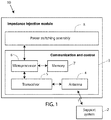
- FIG. 1 is a block diagram of an impedance injection module 10 having a wireless interface 1 to a support system 2, which provides configuration parameters to impedance injection module 10 in accordance with a system-level plan to optimize power flow in a transmission line of a high voltage power distribution system, as well as reconfiguration parameters as power flow characteristics vary with changing power source and load conditions and/or on redeployment of the impedance injection module.
- Such configuration and reconfiguration parameters may be provided wirelessly through the support system 2 of Figure 1 , thereby allowing the parameters to be as frequently updated as desired without physical access to the modules.
- Impedance injection module 10 includes a communication and control block 3 which comprises an antenna 4 for receiving and transmitting wireless signals 1, a transceiver 5 coupled to antenna 4, and a microprocessor 6 coupled to the transceiver 5 and to a memory 7.
- Memory 7 contains instructions executable by microprocessor 6 for operating impedance injection module 10, including transmission of configuration parameters to power switching assembly 8, to be further described in reference to figures 2-3 .
- Memory 7 also includes a nonvolatile rewrite section that may be programed (data and/or instructions) by the support system 2 through transceiver 5 as software configuration programming to configure, and reconfigure as necessary, each of the individual impedance injection modules 10 as previously described.
- impedance injection module 10 may be configured or reconfigured and controlled as required, by a remote support system 2 as desired.
- Impedance injection module 10 may further include elements that are not shown, such as by way of example, a battery, heat dissipation elements, and discrete filter components.
- each of the impedance injection modules is configurable to adjust line reactance while having a smaller effect on line resistance.
- FIG 2 is a circuit schematic for power switching assembly 8, implemented as a full bridge in an exemplary embodiment of an impedance injection module of the present invention.
- Terminals 21 and 22 connect in series with the transmission line as shown in Figure 3 as connections 21b and 22b for the B phase of the transmission lines.
- Device 23 includes a high-power switch 24 with a control input 25, the control value to be determined by the microprocessor 6 in each impedance injection module 10.
- the control input is a one bit digital value per power switching device 23 that is subsequently amplified to drive each power switching device 23 at their respective control inputs 25.
- the desired instantaneous impedance is injected into the power line at terminals 21 and 22.
- the high-power switch 24 depicted is an insulated gate bipolar transistor (IGBT). However, a thyristor, a metal oxide semiconductor field effect transistors (MOSFET), a gate turn-off thyristor (GTO) or other power switching device may be used.
- the high-power switches 24 may employ silicon, silicon carbide, or gallium nitride semiconductors as non-limiting examples.
- Diodes 26 are body (or substrate) to drain diodes in each high-power switch 24 ( Figure 2 ) of each impedance injection module 10.
- each full bridge 8 in each impedance injection module 10 can be activated to store on the link capacitor 27 a DC voltage of either polarity and inject the DC voltage stored on link capacitor 27 at the appropriate times and with the desired polarity within one cycle of the line current waveform.
- the DC voltage stored on link capacitor 27 can be instantaneously reduced as required by turning on a pair of the high-power switches 24 at the correct moment in a power cycle.
- a half-bridge converter may be used in place of a full bridge.
- the impedance injection may be capacitive or inductive as needed or desired by appropriate control of switching devices 23 ( Figure 2 ).
- FIG. 3 depicts a power flow control system 30a in an embodiment of the present invention.
- Power flow control system 30a may be described as a bank of transformerless static synchronous series converters (TL-SSSC), described herein as transformerless converters, each in the form of an impedance injection module 10 that injects a pre-determined (controllable) waveform onto a phase of a power transmission system wherein the waveform is synchronous with the line current, and wherein the transformerless converter comprises stationary (static, non-moving or non-rotating) equipment, and also comprises components connected in series with the line.
- TL-SSSC transformerless static synchronous series converters
- Three phases labeled A, B, C are shown, representing three power transmission lines of a high voltage power distribution system forming a part of the grid and carrying electrical power from a three-phase power source 31, each phase carrying an identical power flow control system 30a, 30b, 30c.
- Power source 31 may be a substation for example, or some other power source, such as a mechanical power generator, a solar farm, etc.
- Phase A includes X AU 33a, the upstream impedance of the transmission line, and carries an electric current I A 34, shown as a vector quantity having both magnitude and direction.
- X AD 33b is the downstream impedance of the transmission line.
- I A may be represented as a sine wave versus time, having an amplitude and an instantaneous phase angle.
- a bank 35 of impedance injection modules 10 is shown, configured as an m x n matrix of impedance injection modules, wherein each impedance injection module is capable of impressing a synthesized impedance to the current flowing on line A 32, I A 34.
- Each impedance injection module 10 impresses the synthesized impedance across terminals such as 21b and 22b in phase B of the figure, where terminals 21 and 22 are defined in reference to figure 2 .
- Variables m 36 and n 37 are each an integer in a typical range of 1-2,000, allowing for application to power transmission systems across a broad range of operating voltages and currents, while improving the efficiency of power transmission through power flow control system 30a.
- m equals the number of impedance injection modules in series in a leg of the bank of impedance injection modules.
- n equals the number of parallel legs in the bank of impedance injection modules.
- m equals the number of impedance injection modules in series in a leg of the bank of impedance injection modules.
- n equals the number of parallel legs in the bank of impedance injection modules.
- m equals the number of impedance injection modules in series in a leg of the bank of impedance injection modules.
- n equals the number of parallel legs in the bank of impedance injection modules.
- m equals the number of impedance injection modules in series in a leg of the bank of impedance injection modules.
- n equals the number of parallel legs in the bank of impedance injection modules.
- m equals the number of impedance injection modules in series in a leg of the bank of impedance injection modules.
- n equals the number of parallel legs in the bank of impedance injection modules.
- each bank 35 of impedance injection modules 10 may be augmented with a bypass switch 38, further described in cross-referenced patent application, 15/694,605 .
- bypass switch 38 may be activated in response to a fault in a transmission line such as A, B, C, wherein the fault is external to the bank 35 of impedance injection modules 10.
- each impedance injection module 10 in each bank 35 of impedance injection modules 10 is identical, and this standardization leads to an agile power flow control system 30a, wherein the impedance injection modules 10 can be efficiently configured, reconfigured, and replaced if necessary.
- identical as used with reference to identical impedance injection modules means of the same design and construction, though may incorporate parts supplied by more than one vendor.
- each identical impedance injection module will differ from the others in such ways as having a unique serial number and electronic identification, and normally will have programming that may differ from at least some other impedance injection modules in the same power flow control system.
- the configuration and reconfiguration parameters may include parameters that include programming changes allowing the impedance injection modules to collectively be remotely coordinated to execute more than a single power flow control algorithm at different times.
- each of the plurality of impedance injection modules 10 is capable of providing an impedance injection level sufficient to optimize a reactive power transfer of at least 2kVA per kilogram weight of the impedance injection module. Furthermore, in pursuit of a simplified yet capable power flow control system 30a, there are no shunt components connected between the phases: there is no requirement for shunt components, and shunt components are preferably omitted in all embodiments of the present invention. Also, in power flow control system 30a, when installed and in operation, the impedance injection modules 10 float with respect to ground and there is no requirement for a ground isolation transformer.
- the TL-SSSCs (transformerless converters) of the present invention do not require isolation from the transmission line voltage, even though the line voltage may be as high as 765 kV for example. Accordingly, transformers for either ground isolation or line voltage isolation are omitted in all embodiments of the present invention.
- isolation from ground is achieved by spacing the line around 10 meters or more above ground, by shielding the impedance injection modules within metal enclosures, and by providing corona rings (curved annular surfaces) that limit the electric field emanating from an impedance injection module. This limited electric field is insufficient to create corona discharge.
- power flow control system 30a it can be configured to avoid the creation of new sub-synchronous resonances arising from installation of the modular power flow control system; the power flow control system 30a can also be configured to lessen the severity of pre-existing sub-synchronous resonances.
- Sub-synchronous resonances occur at frequencies below the primary transmission frequency which is typically 60 Hz in the United States.
- Lessening the severity of pre-existing sub-synchronous resonances by the power flow control system 30a of the present invention can be achieved by simply tailoring the control of the impedance injections to also simultaneously add to the injections, waveforms counteracting the pre-existing sub-synchronous resonances with no change in the power control systems 30a themselves, thereby preserving the ability to use identical and standardized impedance injection modules.
- the deployment and operation of an impedance injection module includes determining the values of m and n in the one or more banks of impedance injection modules to be deployed at a specified location.
- the value of m will depend on the line impedance and the total voltage injection desired.
- the value of n will be determined by the required current capacity of each phase, given the current capacity of the individual impedance injection modules 10.
- n legs allows the application of lower current capacity impedance injection modules to meet substantially any current requirements for all phases of high current transmission lines while not providing an excessive current capacity for lower current transmission lines.
- m injection modules for each leg allows the tailoring of the voltage injection capacity to the then present requirements, again without providing excessive capacity where such capacity is not needed.
- a single injection module 10 may inject a pair of DC voltages to form a symmetric injection, with one pulse in each half cycle of the injection waveform.
- the fundamental frequency of the injected pair of positive and negative pulses will be asserted, with the remaining frequencies filtered out by the line reactance.
- Figure 4 depicts an exemplary embodiment of a mobile power flow control system 50 of the present invention, provided on wheeled vehicles 51 and 52.
- wheeled vehicle 51 which may be provided in plurality and the TL- SSSC impedance injection modules therein and the impedance injection modules in multiple trailers connected in series and/or parallel
- System 50 is transportable over public and private roads to a convenient site for providing power control in transmission lines 53 of a power transmission system.
- System 50 may be implemented as one or more mobile containers having the desired number of impedance injection modules set up inside, in addition to a bypass switch 38, according to a configuration determined by the support system 2, described in reference to figure 1 , and coupled together, or configured to be coupled together for a particular installation site, as schematically illustrated in Figure 3 , for example.
- the mobile containers may have wheels as shown in figure 4 , or may be transportable within wheeled vehicles.
- system 50 is a dispatchable power flow control system wherein all of the components can be assembled into a tested system prior to dispatch, and not broken down for transport.
- Transmission lines 53 may connect between tower support structures such as tower support 54 upstream of system 50, and tower support 55 downstream of system 50.
- Bypass switch 38 is described in reference to figure 3 and may be transported on a separate wheeled vehicle or trailer, or could be part of each mobile unit.
- Use of a separate wheeled vehicle has the advantage that a plurality of wheeled vehicles 51 may be used in series in each transmission line 53 (or one of the parallel legs "n" in a bank 35 of impedance injection modules, figure 3 ), yet only a single bypass switch need be used for the series combination of wheeled vehicles.
- the synthesis of a power control waveform may be by way of cooperative control of multiple impedance injection modules 10 in multiple banks 35 of impedance injection modules 10.
- the mobile flow control system 50 of figure 4 Since the mobile flow control system 50 of figure 4 operates in a parked location on the ground, it requires isolation from ground, in contrast with the power flow control system 30a described in reference to figure 3 .
- This isolation may be provided by post insulators, string insulators, or by other methods, typically elevating the high voltage elements adequately above the ground level to provide the required isolation.
- Such elevating devices and structures may be provided as part of the wheeled vehicles 51 and 52, by being provided by other wheeled vehicles and/or by way of preexisting, modified or erected structures for such use, with anything modified or erected for such use preferably being readily disassembleable for reconfiguring, or for transport and reassembly for redeployment at another location.
- the wheeled vehicles 51 are truck trailers specifically built or modified for the intended purpose, and may incorporate the elevating mechanisms including associated insulating pedestals for supporting and insulating the TL-SSSC modules once deployed to their operating location .
- the elevating mechanisms may be capable for elevating such devices and then turning them, or allowing them to be turned, to their angular orientation for use.
- various systems and subsystems to be deployed can be pre-configured in the trailers, and to the extent that on-site assembly and/or interconnection is necessary, all jumpers and other hardware may be prefabricated, labeled and provided in the respective wheeled vehicle transporting the devices on which the hardware will be used.
- all jumpers, etc. needed to interconnect devices on multiple wheeled vehicles, if not pre-assembled may at least be pre-fabricated to properly interconnect such devices (trailers) once the trailers are parked in the desired positions, which positions are also pre-laid out.
- the time to deploy is greatly reduced, as is the time of debugging and verifying the system once deployed.
- Figure 5 is a flow chart 60 depicting a method for installing a modular power flow control system for optimizing power transmission on a three-phase transmission line, in an embodiment of the present invention.
- module means impedance injection module.
Applications Claiming Priority (2)
| Application Number | Priority Date | Filing Date | Title |
|---|---|---|---|
| US201862622441P | 2018-01-26 | 2018-01-26 | |
| US16/104,778 US10756542B2 (en) | 2018-01-26 | 2018-08-17 | Agile deployment of optimized power flow control system on the grid |
Publications (2)
| Publication Number | Publication Date |
|---|---|
| EP3518366A2 true EP3518366A2 (de) | 2019-07-31 |
| EP3518366A3 EP3518366A3 (de) | 2019-10-09 |
Family
ID=65200656
Family Applications (1)
| Application Number | Title | Priority Date | Filing Date |
|---|---|---|---|
| EP19153095.5A Pending EP3518366A3 (de) | 2018-01-26 | 2019-01-22 | Agiler einsatz von optimiertem stromflusssteuerungssystem im netz |
Country Status (3)
| Country | Link |
|---|---|
| US (1) | US10756542B2 (de) |
| EP (1) | EP3518366A3 (de) |
| CN (1) | CN110086174B (de) |
Cited By (7)
| Publication number | Priority date | Publication date | Assignee | Title |
|---|---|---|---|---|
| WO2021013341A1 (de) * | 2019-07-23 | 2021-01-28 | Siemens Energy Global GmbH & Co. KG | Vorrichtung zum verbinden zweier wechselspannungsnetze und verfahren zum betreiben der vorrichtung |
| EP3823126A1 (de) * | 2019-11-15 | 2021-05-19 | Smart Wires Inc. | Adaptive regelungstechnik für die stabilität einer impedanzinjektionseinheit |
| EP3826126A1 (de) * | 2019-11-22 | 2021-05-26 | Smart Wires Inc. | Verwendung der ungenutzten dauereinspritzeinheiten in einer anordnung zur verminderung von oszillationen während der impedanzinjektion für korrekturen von problemen |
| CN113098307A (zh) * | 2021-04-16 | 2021-07-09 | 南京工程学院 | 带储能的串并联混合多电平变换器及双重移相pwm控制方法 |
| EP3913786A1 (de) * | 2020-05-18 | 2021-11-24 | Siemens Aktiengesellschaft | Stromrichteranordnung mit einem netzgeführten stromrichter sowie verfahren zum anfahren der stromrichteranordnung |
| EP3934041A3 (de) * | 2020-07-01 | 2022-01-19 | Smart Wires Inc. | Schutz gegen und filtrierung von störungen für serielle verbundene fakten |
| EP3979483A1 (de) * | 2020-10-05 | 2022-04-06 | Hitachi Energy Switzerland AG | Transformatoranordnung und verfahren zur spannungsumwandlung |
Families Citing this family (6)
| Publication number | Priority date | Publication date | Assignee | Title |
|---|---|---|---|---|
| WO2018068799A1 (en) * | 2016-10-12 | 2018-04-19 | Vestas Wind Systems A/S | Improvements relating to reactive power control in wind power plants |
| EP3596743A4 (de) * | 2017-03-17 | 2020-09-09 | Georgia Tech Research Corporation | Hybride transformatorsysteme und verfahren |
| US10998825B2 (en) * | 2018-02-12 | 2021-05-04 | The Texas A&M University System | Method and apparatus for medium-voltage electronic power conversion |
| US10396533B1 (en) * | 2018-02-22 | 2019-08-27 | Smart Wires Inc. | Containerized power flow control systems |
| US11641102B2 (en) * | 2020-03-10 | 2023-05-02 | Smart Wires Inc. | Modular FACTS devices with external fault current protection within the same impedance injection module |
| US20220037014A1 (en) * | 2020-07-28 | 2022-02-03 | Smart Wires Inc. | Prognostics and Diagnostics of Injection Units and Communications |
Citations (1)
| Publication number | Priority date | Publication date | Assignee | Title |
|---|---|---|---|---|
| US20190006835A1 (en) | 2017-06-30 | 2019-01-03 | Smart Wires Inc. | Modular FACTS Devices with External Fault Current Protection |
Family Cites Families (89)
| Publication number | Priority date | Publication date | Assignee | Title |
|---|---|---|---|---|
| US3955657A (en) | 1974-02-15 | 1976-05-11 | Oscar Bossi | Electric traction transportation system with storage battery powered vehicles and fast recharge at the vehicle stops |
| USRE29994E (en) | 1973-02-15 | 1979-05-15 | Electric traction transportation system with storage battery powered vehicles and fast recharge at the vehicle stops | |
| US3959985A (en) | 1975-02-18 | 1976-06-01 | General Electric Company | Air conditioning system for a mobile home including an interlock |
| US4167670A (en) | 1978-02-03 | 1979-09-11 | General Electric Company | Dental X-ray apparatus |
| US4188536A (en) | 1978-02-03 | 1980-02-12 | General Electric Company | Dental x-ray apparatus |
| US4355351A (en) | 1979-05-30 | 1982-10-19 | Schwarz Francisc C | High repetition rate power pulse generator |
| US4293902A (en) | 1979-12-04 | 1981-10-06 | Ael Mirrotel, Ltd. | Transformerless fast current limiter with symetry correction for a switched-mode power supply |
| US4322817A (en) | 1980-12-29 | 1982-03-30 | Gte Automatic Electric Labs Inc. | Switching regulated pulse width modulated push-pull converter |
| US4683461A (en) | 1985-09-17 | 1987-07-28 | Allied Corporation | Inductive magnetic field generator |
| US4823250A (en) | 1987-11-05 | 1989-04-18 | Picker International, Inc. | Electronic control for light weight, portable x-ray system |
| US5340326A (en) | 1988-07-18 | 1994-08-23 | Lemaster Dolan M | Connectivity management system |
| US5149277A (en) | 1988-07-18 | 1992-09-22 | Lemaster Dolan M | Connectivity management system |
| US4908569A (en) | 1988-08-09 | 1990-03-13 | Fest Otto P | Transformerless line powdered digital AC voltmeter |
| ATE111173T1 (de) | 1991-02-12 | 1994-09-15 | Plasser Bahnbaumasch Franz | Reinigungsmaschine. |
| US5216285A (en) | 1992-02-24 | 1993-06-01 | Gunderson, Inc. | Freight car with electrical power distribution |
| US5270913A (en) | 1992-04-06 | 1993-12-14 | D.C. Transformation, Inc. | Compact and efficient transformerless power conversion system |
| US5741605A (en) | 1996-03-08 | 1998-04-21 | Westinghouse Electric Corporation | Solid oxide fuel cell generator with removable modular fuel cell stack configurations |
| US5875235A (en) | 1997-03-07 | 1999-02-23 | S3, Incorporated | Transformerless data access arrangement |
| US5917779A (en) | 1997-04-16 | 1999-06-29 | Gabriel, Inc. | Transformerless LED driving circuit |
| US5949148A (en) | 1997-07-18 | 1999-09-07 | Wagner; William F. | D.C. power distribution and fuse panel unit |
| KR100244979B1 (ko) | 1997-08-14 | 2000-02-15 | 서정욱 | 부호분할다중접속 방식의 개인휴대통신용 마이크로셀룰라 이동통신 시스템 |
| US5892351A (en) | 1997-08-29 | 1999-04-06 | Compaq Computer Corporation | DC-isolated converting battery module |
| US6134105A (en) | 1998-01-06 | 2000-10-17 | Lueker; Mark David | Portable command center |
| US6340851B1 (en) | 1998-03-23 | 2002-01-22 | Electric Boat Corporation | Modular transformer arrangement for use with multi-level power converter |
| EP0951126B1 (de) | 1998-04-15 | 2009-07-22 | Mitsubishi Electric Corporation | Kompensationsvorrichtung und Leistungsübertragungssystem damit |
| US6397156B1 (en) | 1998-11-17 | 2002-05-28 | Abb Inc. | Impedance measurement system for power system transmission lines |
| US6296065B1 (en) | 1998-12-30 | 2001-10-02 | Black & Decker Inc. | Dual-mode non-isolated corded system for transportable cordless power tools |
| US6643566B1 (en) | 1999-01-12 | 2003-11-04 | Powerdsine Ltd. | System for power delivery over data communication cabling infrastructure |
| US6061259A (en) | 1999-08-30 | 2000-05-09 | Demichele; Glenn | Protected transformerless AC to DC power converter |
| US6198257B1 (en) | 1999-10-01 | 2001-03-06 | Metropolitan Industries, Inc. | Transformerless DC-to-AC power converter and method |
| US6356467B1 (en) | 1999-10-01 | 2002-03-12 | Metropolitan Industries, Inc. | DC/DC boost converter with bypass circuitry |
| US20020057342A1 (en) | 2000-11-13 | 2002-05-16 | Takashi Yoshiyama | Surveillance system |
| US6489694B1 (en) | 2002-01-22 | 2002-12-03 | Jacob Chass | Ferrofluidic, electrical power generator |
| WO2003085216A1 (en) | 2002-04-04 | 2003-10-16 | F.I.D.A. S.P.A. | Expandable unit, in particular for houses or offices |
| DE10249437A1 (de) | 2002-10-24 | 2004-06-24 | Daimlerchrysler Ag | Anordnung eines Stromerzeugungssystems in einem Elektrofahrzeug und Verfahren zur Montage bzw. zum Einbau des Stromerzeugungssystems in das Elektrofahrzeug |
| AU2003285140A1 (en) | 2002-11-01 | 2004-06-07 | Rudy Kraus | Apparatus for providing high quality power |
| EP1435522B1 (de) | 2002-12-30 | 2006-09-06 | Evolium S.A.S. | Messung des Spannungsstehwellenverhältnisses mit Fehlerkompensation |
| US7105952B2 (en) | 2003-10-03 | 2006-09-12 | Soft Switching Technologies Corporation | Distributed floating series active impendances for power transmission systems |
| WO2005067117A1 (ja) | 2004-01-09 | 2005-07-21 | The Circle For The Promotion Of Science And Engineering | 電力制御装置 |
| EP1737098A1 (de) | 2005-06-24 | 2006-12-27 | Abb Research Ltd. | Dämpfung von elektromagnetischen Schwingungen in einem Leistungsystem |
| TW200709544A (en) | 2005-08-29 | 2007-03-01 | Ind Tech Res Inst | Transformer-free power conversion circuit for parallel connection with commercial electricity system |
| US20070230094A1 (en) | 2006-04-04 | 2007-10-04 | Carlson Curt S | Integrated, self-contained power distribution system |
| KR100776352B1 (ko) | 2006-04-25 | 2007-11-15 | 한국전력공사 | Scada와 연계한 upfc의 자동운전 시스템 및 그방법 |
| US7453710B2 (en) | 2006-04-26 | 2008-11-18 | Power Integrations, Inc. | Transformerless safety isolation in a power supply using safety capacitors for galvanic isolation |
| NZ550043A (en) | 2006-09-21 | 2008-01-31 | Eaton Power Quality Company | A switched mode power supply and method of production |
| EP1909370A1 (de) | 2006-10-05 | 2008-04-09 | Abb Research Ltd. | Berechnung und Gebrauch von Empfindlichkeitsfaktoren für die Leistungsabflussregelung |
| KR100827571B1 (ko) | 2006-10-31 | 2008-05-07 | 한국전력공사 | Scada 온라인 facts 시뮬레이터 시스템 |
| US8189351B2 (en) | 2007-02-23 | 2012-05-29 | Astec International Limited | Multi-input DC/DC converters with zero-current switching |
| CN100511910C (zh) * | 2007-07-31 | 2009-07-08 | 湖南大学 | 注入式混合有源电力滤波器的电流及直流侧电压控制方法 |
| US7729147B1 (en) | 2007-09-13 | 2010-06-01 | Henry Wong | Integrated circuit device using substrate-on-insulator for driving a load and method for fabricating the same |
| US20090173033A1 (en) | 2008-01-03 | 2009-07-09 | Robert Charles Baxter, JR. | Folding Truss System With Integrated Entertainment Technology Equipment and Method Thereof |
| CN101939932A (zh) | 2008-02-08 | 2011-01-05 | 松下航空电子公司 | 用于在旅行途中在移动平台上分发内容的光通信系统和方法 |
| EP2144358B1 (de) | 2008-07-09 | 2012-02-08 | SMA Solar Technology AG | DC/DC-Wandler |
| US20120085612A1 (en) | 2009-02-20 | 2012-04-12 | Churchill Frederick | Vehicle propulsion energy and utility power delivery system |
| CA2768101A1 (en) | 2009-09-15 | 2011-03-24 | The University Of Western Ontario | Utilization of distributed generator inverters as statcom |
| DK2548277T3 (en) | 2010-03-15 | 2016-01-11 | Alstom Technology Ltd | Static reactive power compensator with flertrinskonverter |
| TW201205253A (en) | 2010-07-30 | 2012-02-01 | Hon Hai Prec Ind Co Ltd | Container data center and heat dissipating system thereof |
| WO2012013248A1 (en) | 2010-07-30 | 2012-02-02 | Areva T&D Uk Limited | Hvdc converter comprising fullbridge cells for handling a dc side short circuit |
| CN102063166A (zh) | 2010-11-17 | 2011-05-18 | 华为技术有限公司 | 集装箱式数据中心 |
| US8434657B2 (en) | 2011-06-09 | 2013-05-07 | Landoll Corporation | Gantry-based welding system and method |
| US8210418B1 (en) | 2011-06-09 | 2012-07-03 | Landoll Corporation | Multi-station, gantry-based automated welding system |
| CN102313850B (zh) | 2011-06-24 | 2014-07-23 | 中国电力科学研究院 | 一种柔性直流输电系统的物理实时动态模拟装置 |
| EP2549638A1 (de) | 2011-07-19 | 2013-01-23 | AEG Power Solutions B.V. | Stromversorgungsanordnung für einen Reaktor zur Polysiliciumherstellung mit einem Frequenzumrichter |
| WO2013037846A1 (en) | 2011-09-12 | 2013-03-21 | Alstom Technology Ltd | Sub-synchronous oscillation damping by shunt facts apparatus |
| US9014867B2 (en) | 2011-09-16 | 2015-04-21 | Varentec, Inc. | Systems and methods for edge of network voltage control of a power grid |
| US20130068271A1 (en) | 2011-09-20 | 2013-03-21 | Mohammad Jamil Ahmad Bqoor | Prototype Thermoelectric Generator Based on Ionized Gas in a Container Under Electric Potential Difference |
| US8649883B2 (en) | 2011-10-04 | 2014-02-11 | Advanergy, Inc. | Power distribution system and method |
| US20130155662A1 (en) | 2011-11-17 | 2013-06-20 | Eaton Industries (Austria) Gmbh | Modular Lighting System |
| FR2985394B1 (fr) | 2011-12-28 | 2014-01-31 | Alstom Hydro France | Installation de production d'electricite comportant une pluralite de dispositifs de production d'electricite aptes a transformer de l'energie mecanique en energie electrique. |
| AT512385B1 (de) | 2012-01-04 | 2015-08-15 | Coil Holding Gmbh | Vorrichtung zur beeinflussung von blindleistungsflüssen |
| US9246314B2 (en) | 2012-03-30 | 2016-01-26 | Elwha Llc | Mobile device configured to perform tasks related to a power transmission system |
| US20130346571A1 (en) | 2012-06-24 | 2013-12-26 | Sergei MAKAVEEV | Computer and method of operation of its network |
| US9331482B2 (en) | 2012-11-02 | 2016-05-03 | North Carolina State University | Static synchronous compensator systems and related methods |
| ES2648341T3 (es) | 2012-12-28 | 2018-01-02 | Prysmian S.P.A. | Módulo de derivación basado en contenedor para líneas de energía eléctrica |
| US20140312859A1 (en) | 2013-03-27 | 2014-10-23 | Smart Wire Grid, Inc. | Phase balancing of power transmission system |
| JP2015079677A (ja) | 2013-10-17 | 2015-04-23 | 東京エレクトロン株式会社 | マイクロ波プラズマ処理装置及びマイクロ波供給方法 |
| FR3013163B1 (fr) | 2013-11-08 | 2018-09-14 | Airbus Operations | Reseau de distribution d'energie electrique d'un vehicule de transport, tel qu'un avion, ainsi qu'une installation electrique d'un avion |
| BR202013029267U2 (pt) | 2013-11-13 | 2015-10-27 | Aruanã En S A | disposição construtiva introduzida em usina elétrica modular dotada de sistema de transformador de alta tensão para conexão direta em sistema de distribuição de energia integrados em contêineres ou similares |
| US9332602B2 (en) | 2013-12-12 | 2016-05-03 | Genereal Electric Company | LED driver with transformerless hysteretic boost |
| US10048195B2 (en) | 2014-01-31 | 2018-08-14 | The Boeing Company | Oxygen analysis system and method for measuring, monitoring and recording oxygen concentration in aircraft fuel tanks |
| US20150293517A1 (en) | 2014-04-09 | 2015-10-15 | Adam Chase Higgins | Mobile application and control system |
| KR101628920B1 (ko) | 2014-07-31 | 2016-06-10 | 고려대학교 산학협력단 | 전력계통 주파수 유연화 운영 시스템 및 그 방법 |
| JP3217277U (ja) | 2014-10-23 | 2018-08-02 | アルアナ エネルギア エス/アー | 発電プラントモジュールに導入される構成デバイス |
| AU2016222134B2 (en) | 2015-02-20 | 2020-07-16 | Noble Drilling A/S | Power generation and distribution system for offshore drilling units |
| US9473028B1 (en) | 2015-04-29 | 2016-10-18 | Hamilton Sundstrand Corporation | Systems and methods for controlling power converters |
| CN105391329B (zh) | 2015-12-11 | 2017-11-17 | 华中科技大学 | 一种全桥型mmc交流电压提升运行方法 |
| US10218175B2 (en) | 2016-02-11 | 2019-02-26 | Smart Wires Inc. | Dynamic and integrated control of total power system using distributed impedance injection modules and actuator devices within and at the edge of the power grid |
| KR102145029B1 (ko) | 2017-04-28 | 2020-08-14 | 엘에스일렉트릭(주) | 서브모듈 슬라이딩장치 |
| KR101950442B1 (ko) | 2017-04-28 | 2019-02-20 | 엘에스산전 주식회사 | 서브모듈 |
-
2018
- 2018-08-17 US US16/104,778 patent/US10756542B2/en active Active
-
2019
- 2019-01-22 EP EP19153095.5A patent/EP3518366A3/de active Pending
- 2019-01-28 CN CN201910080385.XA patent/CN110086174B/zh active Active
Patent Citations (1)
| Publication number | Priority date | Publication date | Assignee | Title |
|---|---|---|---|---|
| US20190006835A1 (en) | 2017-06-30 | 2019-01-03 | Smart Wires Inc. | Modular FACTS Devices with External Fault Current Protection |
Cited By (10)
| Publication number | Priority date | Publication date | Assignee | Title |
|---|---|---|---|---|
| WO2021013341A1 (de) * | 2019-07-23 | 2021-01-28 | Siemens Energy Global GmbH & Co. KG | Vorrichtung zum verbinden zweier wechselspannungsnetze und verfahren zum betreiben der vorrichtung |
| EP3823126A1 (de) * | 2019-11-15 | 2021-05-19 | Smart Wires Inc. | Adaptive regelungstechnik für die stabilität einer impedanzinjektionseinheit |
| US11349310B2 (en) * | 2019-11-15 | 2022-05-31 | Smart Wires Inc. | Adaptive control technique for stability of impedance injection unit |
| EP3826126A1 (de) * | 2019-11-22 | 2021-05-26 | Smart Wires Inc. | Verwendung der ungenutzten dauereinspritzeinheiten in einer anordnung zur verminderung von oszillationen während der impedanzinjektion für korrekturen von problemen |
| EP3913786A1 (de) * | 2020-05-18 | 2021-11-24 | Siemens Aktiengesellschaft | Stromrichteranordnung mit einem netzgeführten stromrichter sowie verfahren zum anfahren der stromrichteranordnung |
| US11641154B2 (en) | 2020-05-18 | 2023-05-02 | Siemens Energy Global GmbH & Co. KG | Power converter assembly with a line-commutated power converter and method for starting up the assembly |
| EP3934041A3 (de) * | 2020-07-01 | 2022-01-19 | Smart Wires Inc. | Schutz gegen und filtrierung von störungen für serielle verbundene fakten |
| EP3979483A1 (de) * | 2020-10-05 | 2022-04-06 | Hitachi Energy Switzerland AG | Transformatoranordnung und verfahren zur spannungsumwandlung |
| WO2022073919A1 (en) * | 2020-10-05 | 2022-04-14 | Hitachi Energy Switzerland Ag | Transformer arrangement and method for voltage conversion |
| CN113098307A (zh) * | 2021-04-16 | 2021-07-09 | 南京工程学院 | 带储能的串并联混合多电平变换器及双重移相pwm控制方法 |
Also Published As
| Publication number | Publication date |
|---|---|
| CN110086174B (zh) | 2024-03-26 |
| US20190237971A1 (en) | 2019-08-01 |
| CN110086174A (zh) | 2019-08-02 |
| EP3518366A3 (de) | 2019-10-09 |
| US10756542B2 (en) | 2020-08-25 |
Similar Documents
| Publication | Publication Date | Title |
|---|---|---|
| US10756542B2 (en) | Agile deployment of optimized power flow control system on the grid | |
| KR101670309B1 (ko) | 컨버터 | |
| US8760826B2 (en) | Bipolar DC to AC power converter with DC ground fault interrupt | |
| US10523132B2 (en) | Start-up of HVDC converters | |
| US8779730B2 (en) | Capacitor discharge in a cell based voltage source converter | |
| US10637371B2 (en) | Interface arrangement between an alternating current power system and a direct current power system with control of converter valve for fault protection | |
| JP2007507999A (ja) | 送電システムのための分散浮動型直列的能動インピーダンス | |
| US20140043882A1 (en) | Modular Power Converters Usable Alone or In A Multiphase Power Converter | |
| US20160013653A1 (en) | Converter station with diode rectifier | |
| EP3032680A1 (de) | Standby- und Laden von modularen mehrstufigen Wandlern | |
| US10505467B2 (en) | Converter station with diode rectifier | |
| CN102035398B (zh) | 直接转换器以及具有这种直接转换器的系统 | |
| AU2011201307A1 (en) | DC transmission system for remote solar farms | |
| EP3288169B1 (de) | Stromwandlungsvorrichtung | |
| EP2993771B1 (de) | Systeme und verfahren zum verbesserte betrieb und schutz von leistungswandlern | |
| CN105281355A (zh) | 多级功率转换器 | |
| EP4324084A1 (de) | Spannungsklemme und stromklemmensysteme mit leistungsrückgewinnung | |
| US10770870B2 (en) | Containerized power flow control systems | |
| AU2019204500A1 (en) | Agile deployment of optimized power flow control system on the grid | |
| WO2018100051A1 (en) | Improvements in or relating to hvdc power converters | |
| Tanaka et al. | Reactive power compensation capability of a STATCOM based on two types of Modular Multilevel Cascade Converters for offshore wind application | |
| EP3754831A1 (de) | System zur umwandlung von elektrischem strom und zugehöriges verfahren | |
| WO2018166846A1 (en) | Grounding arrangment for a voltage source converter | |
| EP3142239A1 (de) | Vorladung eines modularen mehrstufigen umrichters | |
| ES2866178T3 (es) | Conmutador, sistema distribuidor y método de ajuste del desequilibrio de la corriente o de las tensiones de fase a neutro |
Legal Events
| Date | Code | Title | Description |
|---|---|---|---|
| PUAI | Public reference made under article 153(3) epc to a published international application that has entered the european phase |
Free format text: ORIGINAL CODE: 0009012 |
|
| STAA | Information on the status of an ep patent application or granted ep patent |
Free format text: STATUS: THE APPLICATION HAS BEEN PUBLISHED |
|
| AK | Designated contracting states |
Kind code of ref document: A2 Designated state(s): AL AT BE BG CH CY CZ DE DK EE ES FI FR GB GR HR HU IE IS IT LI LT LU LV MC MK MT NL NO PL PT RO RS SE SI SK SM TR |
|
| AX | Request for extension of the european patent |
Extension state: BA ME |
|
| PUAL | Search report despatched |
Free format text: ORIGINAL CODE: 0009013 |
|
| AK | Designated contracting states |
Kind code of ref document: A3 Designated state(s): AL AT BE BG CH CY CZ DE DK EE ES FI FR GB GR HR HU IE IS IT LI LT LU LV MC MK MT NL NO PL PT RO RS SE SI SK SM TR |
|
| AX | Request for extension of the european patent |
Extension state: BA ME |
|
| RIC1 | Information provided on ipc code assigned before grant |
Ipc: H02J 3/18 20060101AFI20190903BHEP Ipc: H02J 3/20 20060101ALI20190903BHEP |
|
| STAA | Information on the status of an ep patent application or granted ep patent |
Free format text: STATUS: REQUEST FOR EXAMINATION WAS MADE |
|
| 17P | Request for examination filed |
Effective date: 20200319 |
|
| RBV | Designated contracting states (corrected) |
Designated state(s): AL AT BE BG CH CY CZ DE DK EE ES FI FR GB GR HR HU IE IS IT LI LT LU LV MC MK MT NL NO PL PT RO RS SE SI SK SM TR |
|
| STAA | Information on the status of an ep patent application or granted ep patent |
Free format text: STATUS: EXAMINATION IS IN PROGRESS |
|
| 17Q | First examination report despatched |
Effective date: 20210716 |
|
| P01 | Opt-out of the competence of the unified patent court (upc) registered |
Effective date: 20230511 |