EP3518144A1 - Appareil d'authentification biométrique et procédé d'authentification biométrique - Google Patents
Appareil d'authentification biométrique et procédé d'authentification biométrique Download PDFInfo
- Publication number
- EP3518144A1 EP3518144A1 EP19153703.4A EP19153703A EP3518144A1 EP 3518144 A1 EP3518144 A1 EP 3518144A1 EP 19153703 A EP19153703 A EP 19153703A EP 3518144 A1 EP3518144 A1 EP 3518144A1
- Authority
- EP
- European Patent Office
- Prior art keywords
- image
- biometric
- distance
- human body
- biometric authentication
- Prior art date
- Legal status (The legal status is an assumption and is not a legal conclusion. Google has not performed a legal analysis and makes no representation as to the accuracy of the status listed.)
- Granted
Links
- 238000000034 method Methods 0.000 title claims description 29
- 238000003384 imaging method Methods 0.000 claims abstract description 58
- 210000003811 finger Anatomy 0.000 claims description 47
- 238000009826 distribution Methods 0.000 claims description 35
- 210000004932 little finger Anatomy 0.000 claims description 5
- 210000003813 thumb Anatomy 0.000 claims description 4
- 238000001514 detection method Methods 0.000 description 60
- 238000010586 diagram Methods 0.000 description 24
- 238000006243 chemical reaction Methods 0.000 description 17
- 230000010365 information processing Effects 0.000 description 12
- 210000003462 vein Anatomy 0.000 description 9
- 238000004891 communication Methods 0.000 description 5
- 230000003287 optical effect Effects 0.000 description 5
- 238000005401 electroluminescence Methods 0.000 description 3
- 210000004247 hand Anatomy 0.000 description 3
- 239000000284 extract Substances 0.000 description 2
- 239000004973 liquid crystal related substance Substances 0.000 description 2
- 239000004065 semiconductor Substances 0.000 description 2
- 230000009466 transformation Effects 0.000 description 2
- 238000010420 art technique Methods 0.000 description 1
- 210000004204 blood vessel Anatomy 0.000 description 1
- 230000000295 complement effect Effects 0.000 description 1
- 238000011161 development Methods 0.000 description 1
- 230000018109 developmental process Effects 0.000 description 1
- 238000005286 illumination Methods 0.000 description 1
- 229910044991 metal oxide Inorganic materials 0.000 description 1
- 150000004706 metal oxides Chemical class 0.000 description 1
- 230000037303 wrinkles Effects 0.000 description 1
Images


Classifications
-
- G—PHYSICS
- G06—COMPUTING; CALCULATING OR COUNTING
- G06V—IMAGE OR VIDEO RECOGNITION OR UNDERSTANDING
- G06V40/00—Recognition of biometric, human-related or animal-related patterns in image or video data
- G06V40/60—Static or dynamic means for assisting the user to position a body part for biometric acquisition
- G06V40/67—Static or dynamic means for assisting the user to position a body part for biometric acquisition by interactive indications to the user
-
- G—PHYSICS
- G06—COMPUTING; CALCULATING OR COUNTING
- G06F—ELECTRIC DIGITAL DATA PROCESSING
- G06F21/00—Security arrangements for protecting computers, components thereof, programs or data against unauthorised activity
- G06F21/30—Authentication, i.e. establishing the identity or authorisation of security principals
- G06F21/31—User authentication
- G06F21/32—User authentication using biometric data, e.g. fingerprints, iris scans or voiceprints
-
- G—PHYSICS
- G06—COMPUTING; CALCULATING OR COUNTING
- G06F—ELECTRIC DIGITAL DATA PROCESSING
- G06F3/00—Input arrangements for transferring data to be processed into a form capable of being handled by the computer; Output arrangements for transferring data from processing unit to output unit, e.g. interface arrangements
- G06F3/01—Input arrangements or combined input and output arrangements for interaction between user and computer
- G06F3/048—Interaction techniques based on graphical user interfaces [GUI]
- G06F3/0487—Interaction techniques based on graphical user interfaces [GUI] using specific features provided by the input device, e.g. functions controlled by the rotation of a mouse with dual sensing arrangements, or of the nature of the input device, e.g. tap gestures based on pressure sensed by a digitiser
- G06F3/0488—Interaction techniques based on graphical user interfaces [GUI] using specific features provided by the input device, e.g. functions controlled by the rotation of a mouse with dual sensing arrangements, or of the nature of the input device, e.g. tap gestures based on pressure sensed by a digitiser using a touch-screen or digitiser, e.g. input of commands through traced gestures
-
- G—PHYSICS
- G06—COMPUTING; CALCULATING OR COUNTING
- G06V—IMAGE OR VIDEO RECOGNITION OR UNDERSTANDING
- G06V40/00—Recognition of biometric, human-related or animal-related patterns in image or video data
- G06V40/10—Human or animal bodies, e.g. vehicle occupants or pedestrians; Body parts, e.g. hands
- G06V40/12—Fingerprints or palmprints
- G06V40/1365—Matching; Classification
-
- G—PHYSICS
- G06—COMPUTING; CALCULATING OR COUNTING
- G06V—IMAGE OR VIDEO RECOGNITION OR UNDERSTANDING
- G06V40/00—Recognition of biometric, human-related or animal-related patterns in image or video data
- G06V40/10—Human or animal bodies, e.g. vehicle occupants or pedestrians; Body parts, e.g. hands
- G06V40/14—Vascular patterns
- G06V40/145—Sensors therefor
-
- G—PHYSICS
- G06—COMPUTING; CALCULATING OR COUNTING
- G06V—IMAGE OR VIDEO RECOGNITION OR UNDERSTANDING
- G06V40/00—Recognition of biometric, human-related or animal-related patterns in image or video data
- G06V40/10—Human or animal bodies, e.g. vehicle occupants or pedestrians; Body parts, e.g. hands
- G06V40/14—Vascular patterns
Definitions
- biometric authentication techniques have been developed that authenticate a user by using biometric information, such as a fingerprint, a palm print, veins, a face, or the like.
- biometric information such as a fingerprint, a palm print, veins, a face, or the like.
- a biometric authentication apparatus that authenticates a user of a device or a system by using a biometric authentication technique
- matching is performed between input biometric information represented by a biometric image of a person to be authenticated and registration biometric information represented by a biometric image of a person registered in advance.
- the biometric authentication apparatus determines that the input biometric information matches the registration biometric information based on a matching result, the biometric authentication apparatus authenticates a person to be authenticated as a registered person who has an authorized privileges and permits the person to use an apparatus including the biometric authentication apparatus or the other apparatus connected to the biometric authentication apparatus.
- Biometric authentication techniques that use a mobile terminal device and biometric authentication techniques that use a guidance for leading a user's hand or finger, a guidance image, or the like are known.
- Japanese Laid-open Patent Publication No. 2016-173669 Japanese Laid-open Patent Publication No. 2017-097574
- Japanese Laid-open Patent Publication No. 2016-212636 International Publication Pamphlet No. WO 2012/014304
- International Publication Pamphlet No. WO 2013/046365 Japanese Laid-open Patent Publication No. 2010-211579
- Japanese Laid-open Patent Publication No. 2017-136136 Japanese Laid-open Patent Publication No.
- a biometric image of a hand of a user is obtained by displaying an operation guidance figure on the touch panel of a mobile terminal device in a state in which the user is in contact with the touch panel in accordance with the guidance figure.
- the biometric image sometimes becomes unclear.
- the precision of the biometric information detected from the biometric image of the hand deteriorates, and thus the precision of the biometric authentication also deteriorates.
- Such a problem occurs not only in the case of performing biometric authentication using a biometric image but also in the case of performing biometric authentication using the other biometric images.
- a biometric authentication apparatus includes an imaging device, a display device, and a processor configured to display, on a screen of the display device, a guidance indicating a target area to be in contact with a part of a human body, detect whether the part of the human body is in contact with the target area, when the part of the human body is in contact with the target area, determine a distance between the imaging device and another part of the human body in accordance with an image captured by the imaging device, the image including the other part of the human body, and perform a change of a display position of the guidance in accordance with the determined distance.
- the biometric authentication apparatus may achieve improvements of authentication precision in the biometric authentication.
- a biometric authentication apparatus is used in various fields, such as for logon control of a personal computer, for an automated teller machine (ATM) at a bank, entrance and exit management, and the like.
- ATM automated teller machine
- a biometric authentication apparatus capable of being incorporated in a small-sized mobile terminal device, or the like, or a biometric authentication method for use in a small-sized mobile terminal device.
- a user holds a mobile terminal device by one hand and operates a touch panel, or the like disposed on the mobile terminal device so as to use the mobile terminal device.
- a touch panel or the like disposed on the mobile terminal device so as to use the mobile terminal device.
- an operation method is sometimes used in which an operation guidance figure is displayed on a touch panel so as to prompt the user to touch the panel in accordance with the guidance.
- FIGs. 1A and 1B illustrate an example of an acquisition method of a biometric image using a guidance figure displayed on a screen including a display device, which is mounted on a small-sized mobile terminal device, such as a liquid crystal display (LCD), an organic electro luminescence (EL), or the like and a touch panel.
- FIG. 1A illustrates an example of guidance figures displayed on a screen including a display device and a touch panel.
- a mobile terminal device 101 includes a touch panel 102 and a sensor 103.
- the guidance figures displayed on the screen of the touch panel 102 include a mark 104-1 and a mark 104-2 that indicate the positions to be touched by respective fingers, and a guide rail 105-1 and a guide rail 105-2 that indicate respective areas in which the respective marks moves.
- the mark 104-1 moves in the direction indicated by an arrow 106-1 on the guide rail 105-1
- the mark 104-2 moves in the direction indicated by an arrow 106-2 on the guide rail 105-2.
- FIG. 1B illustrates examples in which hands are moved in accordance with the guidance figures.
- the user In a state in which a user brings an index finger of his or her hand 111 into contact with the mark 104-1 and brings a thumb in contact with the mark 104-2, the user traces the guide rail 105-1 and the guide rail 105-2 by the two respective fingers. Thereby, the hand 111 moves in the direction indicated by an arrow 112 and an arrow 113.
- the sensor 103 is a biometric authentication sensor, such as a vein sensor, a camera, or the like and obtains a biometric image of the palm by capturing an image of a palm while the hand 111 is moved.
- the user brings the two fingers into contact with the respective guidance figures so that the shaking of the hand 111 stops and the movement of the hand 111 becomes stable.
- the shaking of the hand 111 stops and the movement of the hand 111 becomes stable.
- FIGs. 2A and 2B illustrate the relationship between the interval of the guide rails and the size of a hand.
- a camera included in the sensor 103 has a fixed depth of field.
- FIG. 2A illustrates an example of a hand suitable for the interval of the guide rails.
- a top view 201 is a view taken from a direction looking down the screen of the touch panel 102
- a side view 202 is a view taken from the side of the touch panel 102.
- the size of a hand 211 is suitable for the interval between the guide rail 105-1 and the guide rail 105-2, and thus it is possible for the user to touch the mark 104-1 and the mark 104-2 with the two respective fingers with a margin in space.
- the distance 221 (height of a palm) between the sensor 103 and the palm is within the depth of field of the sensor 103 in a state in which the two respective fingers are in contact with the mark 104-1 and the mark 104-2. Accordingly, it is possible for the sensor 103 to capture a clear biometric image of the palm, and thus the precision of the biometric information detected from the palm is improved.
- FIG. 2B illustrates an example of a hand not suitable for the interval of the guide rails.
- the size of a hand 212 is small compared with the interval between the guide rail 105-1 and the guide rail 105-2, and each finger becomes shorter in accordance with the size of the hand 212. Accordingly, the user spreads the interval between the two fingers far apart and brings the respective fingers into contact with the mark 104-1 and the mark 104-2.
- the distance between the sensor 103 and the palm is short and becomes out of the depth of field of the sensor 103, and the biometric image of the palm captured by the sensor 103 becomes unclear. Accordingly, the precision of the biometric information detected from the palm deteriorates.
- each finger becomes long in accordance with the size of the hand. Accordingly, it becomes difficult for the user to sufficiently spread the interval of the two fingers and brings the respective fingers in contact with the mark 104-1 and the mark 104-2 at a narrow interval. Thereby, the distance between the sensor 103 and the palm becomes long and out of the depth of field of the sensor 103. Accordingly, the biometric image of the palm becomes unclear, and thus the precision of the biometric information deteriorates.
- FIG. 3 illustrates an example of the functional configuration of the biometric authentication apparatus.
- a biometric authentication apparatus 301 in FIG. 3 includes a display unit 311, a detection unit 312, an imaging unit 313, a determination unit 314, and an authentication unit 315.
- FIG. 4 is a flowchart of biometric authentication processing performed by the biometric authentication apparatus 301 in FIG. 3 .
- the display unit 311 display figures illustrating the target areas to be in contact with parts of a human body on a screen (step 401), and the detection unit 312 detects a contact state in which the parts of a human body are in contact with the two respective target areas (step 402).
- the determination unit 314 determines the distance between the imaging unit 313 and a part of a human body in the contact state (step 403) and changes the figures based on a determination result (step 404).
- the imaging unit 313 captures the image of the part of the human body in the state in which the parts of a human body are in contact with the two respective points in the target areas illustrated by the changed figures so as to obtain the biometric image (step 405).
- the authentication unit 315 performs authentication on the part of the human body based on the biometric image (step 406).
- biometric authentication apparatus 301 it is possible to improve the authentication precision in the biometric authentication in which figures illustrating areas to be in contact with the parts of a human body is displayed to obtain a biometric image.
- FIG. 5 is a functional configuration diagram illustrating a specific example of the biometric authentication apparatus 301 in FIG. 3 .
- the biometric authentication apparatus 301 in FIG. 5 is, for example, a mobile terminal device, such as a smartphone, a tablet, or the like and includes a determination unit 314, an authentication unit 315, a touch panel 501, a sensor 502, a biometric information detection unit 503, and a storage unit 504.
- the storage unit 504 stores guidance information 521 indicating a guidance figure.
- the guidance figures are figures indicating target areas to be in contact with the respective fingers of a user.
- the touch panel 501 includes a display unit 311 and a detection unit 312.
- the display unit 311 displays guidance figures indicated by the guidance information 521 on the screen.
- the display unit 311 it is possible to use a liquid crystal display, an organic electroluminescence display, or the like.
- the detection unit 312 detects the coordinates indicating the positions where the fingers are in contact on the screen and detects the contact state in which the two fingers are in contact with the two respective points in the target area using the detected coordinates.
- the detection unit 312 it is possible to use a touch sensor of a resistance film method, an electrostatic capacitance method, or the like.
- the sensor 502 includes an imaging unit 313, and the imaging unit 313 captures the image of a palm of the user in the contact state in which the two fingers are in contact with the two respective points in the target area and obtains a determination biometric image 522.
- the determination biometric image 522 obtained by the imaging unit 313 is stored in the storage unit 504.
- the imaging unit 313 is a camera including an image sensor, such as a complementary metal oxide semiconductor (CMOS), a charge coupled device (CCD), or the like, and the determination biometric image 522 is a vein image, a palm print image, or the like.
- CMOS complementary metal oxide semiconductor
- CCD charge coupled device
- the determination biometric image 522 is a vein image, a palm print image, or the like.
- a vein sensor is used as the sensor 502
- the sensor 502 radiates near infrared rays, or the like onto the palm to capture the image of the inner blood vessels of the hand, or the like.
- the determination unit 314 includes a feature detection unit 511, a distance determination unit 512, a position determination unit 513, and a change unit 514.
- the feature detection unit 511 detects feature information 523 from the determination biometric image 522 and stores the information in the storage unit 504.
- the distance determination unit 512 determines whether or not the distance between the sensor 502 and the palm is suitable for capturing the image of the hand using the feature information 523.
- the position determination unit 513 determines whether or not the display position of the guidance figure on the screen is suitable for capturing the image of the palm using the feature information 523.
- the change unit 514 changes the guidance information 521 so as to change the shape or the display position of the guidance figure.
- the change unit 514 stores the guidance information 521 at that time in the storage unit 504 as optimum guidance information 524.
- the optimum guidance information 524 represents the guidance figure suitable for the size of the hand of the user.
- the biometric authentication apparatus 301 generates optimum guidance information 524 in registration processing for registering the biometric information of a registered person and displays the optimum guidance information 524 on the screen so as to capture the biometric image of the registered person.
- the biometric authentication apparatus 301 displays the optimum guidance information 524 on the screen so as to capture the biometric image of the person to be authenticated.
- the biometric authentication apparatus 301 In the authentication processing, the biometric authentication apparatus 301 generates optimum guidance information 524 again and displays the optimum guidance information 524 on the screen so as to make it possible to capture the biometric image of a person to be authenticated.
- the display unit 311 displays the guidance figure indicated by the optimum guidance information 524 on the screen, and the detection unit 312 detects a contact state in which the two fingers of the user are in contact with the two respective points in the target area.
- the imaging unit 313 captures the image of the palm in the detected contact state and obtains a biometric image 525, such as a vein image, a palm print image, or the like.
- the biometric image 525 obtained by the imaging unit 313 is stored in the storage unit 504.
- the biometric information detection unit 503 detects biometric information 526 from the biometric image 525 and stores the biometric information 526 in the storage unit 504. For example, if the biometric image 525 is a vein image, the feature quantity of the vein pattern is extracted as the biometric information 526, and if the biometric image 525 is a palm print image, the feature quantity of the palm print is extracted as the biometric information 526. If the user is a registered person, the biometric information detection unit 503 generates registration biometric information 527 including the biometric information 526 and stores the registration biometric information 527 in the storage unit 504.
- the authentication unit 315 compares the biometric information 526 and the registration biometric information 527 and performs authentication on a person to be authenticated based on a comparison result. For example, if the similarity between the biometric information 526 and the registration biometric information 527 is higher than a threshold value, the authentication unit 315 determines that a person to be authenticated is a registered person.
- the display unit 311 displays an authentication result on the screen.
- FIGs. 6A and 6B illustrate an example of adjustment processing in which the biometric authentication apparatus 301 in FIG. 5 changes the guidance information 521.
- FIG. 6A illustrates an example of the guidance figure represented by the guidance information 521 before adjustment.
- a top view 601 is a view taken from a direction looking down the screen of the touch panel 501
- a side view 602 is a view taken from the side of the touch panel 501.
- the guidance figure includes a mark 612-1 and a mark 612-2 that illustrate the target areas to be in contact with the respective fingers.
- the target areas include two areas indicated by the two respective figures of the mark 612-1 and the mark 612-2, and the two respective points in the target area correspond to a point in the area of the mark 612-1 and a point in the area of the mark 612-2.
- the size of the hand 613 is small compared with the distance 622-1 between the mark 612-1 and the mark 612-2, and thus the user spreads the interval between the two fingers far apart so as to bring the respective fingers into contact with the mark 612-1 and the mark 612-2.
- the distance between the sensor 502 and the palm becomes shorter than the depth of field of the imaging unit 313, and the distance determination unit 512 determines that the distance is not suitable for capturing the image of the palm.
- the change unit 514 changes the guidance information 521 so as to change the position of the mark 612-1 in the adjustment range 621-1 and change the position of the mark 612-2 in the adjustment range 621-2. Thereby, the distance 622-1 is changed and the distance 622-2 from the sensor 502 to the mark 612-2 is also changed.
- FIG. 6B illustrates an example of the guidance figure represented by the guidance information 521 after adjustment.
- the distance 623-1 between the mark 612-1 and the mark 612-2 after the adjustment becomes shorter than the distance 622-1 before the adjustment.
- the distance 623-2 from the sensor 502 to the mark 612-2 after the adjustment becomes shorter than the distance 622-2 before the adjustment.
- the distance 623-1 between the positions of the mark 612-1 and the mark 612-2 is adapted for the size of the hand 613, and thus it is possible for the user to bring the two respective fingers into contact with the mark 612-1 and the mark 612-2 with a margin in space.
- the distance 624 between the sensor 502 and the palm is within the depth of field of the sensor 502 in the state in which the two respective fingers are in contact with the mark 612-1 and the mark 612-2. Accordingly, the distance determination unit 512 determines that the distance 624 is suitable for capturing the image of the palm, and the change unit 514 stores the guidance information 521 after the change in the storage unit 504 as optimum guidance information 524.
- the biometric authentication apparatus 301 in FIG. 5 if the distance between the sensor 502 and the palm or the display position of the guidance figure is not suitable for capturing the image of the palm, by changing the shape or the display position of the guidance figure, a suitable guidance figure is displayed. Thereby, it is possible to lead the palm of the user to a position within the depth of field of the imaging unit 313 with a low-cost configuration, and it becomes possible to obtain a clear biometric image. Accordingly, the precision of the biometric information obtained from the biometric image is improved, and the authentication precision of the biometric authentication using the biometric information is also improved.
- FIG. 7 is a flowchart illustrating an example of the registration processing performed by the biometric authentication apparatus 301 in FIG. 5 .
- the display unit 311 displays the guidance figures represented by the guidance information 521 on the screen (step 701)
- the detection unit 312 detects a contact state in which the two fingers of a registered person are in contact with two respective points in the target area (step 702).
- the imaging unit 313 captures the image of the palm of the user in the contact state and obtains the determination biometric image 522 (step 703).
- the feature detection unit 511 detects the feature information 523 from the determination biometric image 522 (step 704), and the distance determination unit 512 determines whether or not a distance D between the sensor 502 and the palm is suitable for capturing the image of the palm using the feature information 523 (step 705).
- step 705 If the distance D is not suitable for capturing the image of the palm (step 705, NO), the change unit 514 changes the guidance information 521 (step 714), and the biometric authentication apparatus 301 repeats the processing of step 701 and the subsequent processing.
- the position determination unit 513 determines whether or not the display positions of the guidance figures are suitable for capturing the image of the palm using the feature information 523 (step 706).
- step 706 NO If the display positions of the guidance figures are not suitable for capturing the image of the palm guidance figure (step 706, NO), the change unit 514 changes the guidance information 521 (step 714), and the biometric authentication apparatus 301 repeats the processing of step 701 and the subsequent processing.
- the change unit 514 registers the guidance information 521 at that time in the storage unit 504 as the optimum guidance information 524 (step 707).
- the display unit 311 displays the guidance figures represented by the optimum guidance information 524 on the screen (step 708), and the detection unit 312 detects a contact state in which the two fingers of a registered person are in contact with two respective points in the target area (step 709).
- the imaging unit 313 captures the image of the palm in the detected contact state and obtains the biometric image 525 (step 710).
- the biometric information detection unit 503 detects the biometric information 526 from the biometric image 525 (step 711), generates registration biometric information 527 including the biometric information 526, and registers the registration biometric information 527 in the storage unit 504 (step 712).
- the biometric authentication apparatus 301 determines whether or not to terminate registering the biometric information (step 713), and if the biometric authentication apparatus 301 determines not to terminate registering the biometric information (step 713, NO), the biometric authentication apparatus 301 repeats the processing of step 701 and the subsequent processing. On the other hand, if the biometric authentication apparatus 301 determines to terminate registering the biometric information (step 713, YES), the biometric authentication apparatus 301 terminates the processing.
- the biometric authentication apparatus 301 determines that the registration of the biometric information has not been terminated and repeats the processing of step 701 and the subsequent processing for the other hand as a registration target.
- the biometric authentication apparatus 301 determines to terminate the registration of the biometric information.
- step 704 in FIG. 7 it is possible for the feature detection unit 511 to detect feature information 523 based on the distribution of the frequency components or the pixel values of the determination biometric image 522.
- FIG. 8 is a flowchart illustrating an example of first feature detection processing for detecting the feature information 523 based on the distribution of the determination biometric image 522.
- the feature detection unit 511 extracts a specific area of a predetermined size from the determination biometric image 522 (step 801) and converts the image of the extracted specific area into signals in the spatial frequency domain (step 802). For example, it is possible for the feature detection unit 511 to converts the image of the extracted specific area into signals in the spatial frequency domain using the two-dimensional fast Fourier transform (FFT).
- FFT fast Fourier transform
- FIG. 9 illustrates an example of a specific area in the determination biometric image 522.
- the specific area 901 in FIG. 9 corresponds to a part of the image of the palm taken in the determination biometric image 522.
- the feature detection unit 511 may use the entire determination biometric image 522 as the specific area in place of the specific area 901.
- FIG. 10 illustrates an example of a conversion result of the specific area by the two-dimensional FFT.
- the horizontal axis of the conversion result in FIG. 10 represents horizontal direction frequency of the determination biometric image 522
- the vertical axis represents vertical direction frequency of the determination biometric image 522
- the conversion result represents the distribution of the frequency components of the determination biometric image 522.
- the origin of conversion result corresponds to the direct current component.
- the conversion result of the specific area includes many high frequency components.
- the distance D is out of the depth of field, and the determination biometric image 522 is unclear, high frequency components are missing from the conversion result of the specific area, and the conversion result including mainly low frequency components is obtained.
- FIG. 11 illustrates an example of the comparison between the conversion result of a clear biometric image and the conversion result of an unclear biometric image.
- a clear biometric image 1101 is obtained as the determination biometric image 522, and the distribution 1111 of the frequency components of the biometric image 1101 includes many high frequency components.
- an unclear biometric image 1102 corresponding to a part of an area 1103 of the biometric image 1101 is obtained as the determination biometric image 522, and a distribution 1112 of the frequency components of the biometric image 1102 hardly includes high frequency components.
- the feature detection unit 511 uses the difference in the distribution of frequency components in accordance with such a distance D to detect high frequency components included in the conversion result so as to determine whether or not the distance D is suitable for capturing the image of the palm.
- the feature detection unit 511 analyzes the distribution of the frequency components indicated by the conversion result of the specific area and detects the amplitudes of the high frequency components (step 803), and calculates a statistical value of the detected amplitudes (step 804). It is possible to use the average value, the median, the maximum value, the minimum value, or the like as the statistical value.
- the feature detection unit 511 analyzes the distribution of the frequency components using a circle 1001 having a radius r1 with the origin of the conversion result as center and a circle 1002 having a radius r2 with the origin as center.
- the radius r2 is larger than the radius r1.
- the feature detection unit 511 detects the amplitude (grayscale value) of each point in the difference area produced by excluding the circle 1001 from the circle 1002 as the amplitude of the high frequency component at a corresponding point and calculates the statistical value of all the amplitudes in the area.
- the area to be used for the high frequency component ought to be an area that excludes direct current components and is not limited to the difference area illustrated in FIG. 10 .
- the entire remaining area produced by excluding the circle 1001 may be used as a high frequency component, or a point on a predetermined line passing the origin may be used as a high frequency component.
- the statistical value of the amplitudes, which has been calculated by the feature detection processing in FIG. 8 is used as the feature information 523 in step 705 in FIG. 7 .
- the distance determination unit 512 compares the statistical value of the amplitudes with a predetermined threshold value. If the statistical value is higher than the threshold value, the distance determination unit 512 determines that the distance D is suitable for capturing the image of the palm, whereas if the statistical value is less than or equal to the threshold value, the distance determination unit 512 determines that the distance D is not suitable for capturing the image of the palm.
- FIG. 12 is a flowchart illustrating an example of second feature detection processing for detecting the feature information 523 based on the distribution of the pixel values of the determination biometric image 522.
- the feature detection unit 511 extracts a specific area of a predetermined size from the determination biometric image 522 (step 1201), and calculates the frequency of the occurrence of the pixels having each pixel value in the extracted specific area (step 1202). For example, it is possible for the feature detection unit 511 to calculate the frequency of the pixel value using the brightness value (grayscale value) as a pixel value.
- FIG. 13 is a diagram illustrating an example of the distribution of the pixel values of the determination biometric image 522.
- a distribution 1301 of the brightness values represents the occurrence frequency of the pixels having individual brightness values in a specific area.
- the sensor 502 includes an illumination optical system
- the sensor 502 emits light onto a palm, and the light reflected from the palm is received by the imaging unit 313 so that the biometric image of the palm is captured. Accordingly, if the distance D between the sensor 502 and the palm is shorter than the depth of field, so-called "blown out highlights” occurs at many positions in the biometric image, and the brightness value of many pixels becomes high at many pixels compared with the case where the distance D is within the depth of field. On the other hand, if the distance D is longer than the depth of field, the biometric image becomes dark, and the brightness value of many pixels becomes low at many pixels compared with the case where the distance D is within the depth of field.
- FIG. 14 is a diagram illustrating an example of the comparison between the distribution of pixel values of a biometric image irradiated with suitable light and the distribution of pixel values of a biometric image in which "blown out highlights" has occurred. If the distance D is within the depth of field, a biometric image 1401 having a suitable brightness is obtained as the determination biometric image 522. On the other hand, if the distance D is shorter than the depth of field, a biometric image 1402 is obtained in which "blown out highlights" has occurred as the determination biometric image 522, which corresponds to a part of area 1403 of the biometric image 1401. A distribution 1412 of the brightness values in the biometric image 1402 is shifted in the direction of higher brightness value compared with a distribution 1411 of the brightness values in the biometric image 1401.
- the feature detection unit 511 determines whether or not the distance D is suitable for capturing the image of a palm by detecting a pixel value having the maximum frequency using the difference in the distribution of pixel values in accordance with the distance D.
- the feature detection unit 511 detects a pixel value corresponding to the maximum frequency of the distribution of the pixel values as a peak value (step 1203).
- the feature detection unit 511 detects a brightness value corresponding to the peak of the distribution 1301 in brightness value as a peak value.
- the feature detection unit 511 it is possible for the feature detection unit 511 to detect a pixel value corresponding to a predetermined range peak as a peak value in place of the pixel value corresponding to the peak in the entire distribution of the pixel values.
- FIG. 15 illustrates an example of the detection processing for detecting a peak value from a predetermined range of the distribution of the pixel values.
- the feature detection unit 511 sets a window having a width W for the distribution 1301 of brightness values and calculates the total frequency by adding the frequencies of a plurality of brightness values of the individual positions in the window while shifting the window by a predetermined step.
- the feature detection unit 511 obtains a position of the window having the maximum total frequency and detects a pixel value corresponding to the peak in the window at the position as a peak value.
- the peak value detected by the feature detection processing in FIG. 12 is used as the feature information 523 in step 705 in FIG. 7 .
- the distance determination unit 512 compares the peak value with a predetermined threshold value and determines whether or not the distance D is suitable for capturing the image of the palm based on the comparison result.
- FIG. 16 illustrates an example of a threshold value with respect to a peak value.
- a threshold value T1 represents a low-frequency threshold value
- a threshold value T2 represents a high-frequency threshold value. If the peak value is equal to or higher than the threshold value T1 and lower than or equal to the threshold value T2, the distance determination unit 512 determines that the distance D is suitable for capturing the image of the palm. If the peak value is lower than the threshold value T1, or the peak value is higher than the threshold value T2, the distance determination unit 512 determines that the distance D is not suitable for capturing the image of the palm.
- step 704 in FIG. 7 it is possible for the feature detection unit 511 to detect the feature information 523 using the technique described in Japanese Laid-open Patent Publication No. 2017-136136 .
- the feature detection unit 511 detects the feature information 523 based on the characteristic of the imaging unit 313, the movement quantity of the contact position when the contact position of the finger has moved on the screen, and the movement quantity of the biometric feature taken in the determination biometric image 522.
- FIG. 17 illustrates an example of the characteristic information of an imaging device disclosed in Japanese Laid-open Patent Publication No. 2017-136136 .
- the horizontal axis in FIG. 17 represents an imaging range f (mm/pix) per pixel of the image captured by the imaging device, the vertical axis represents an imaging distance z (mm), and the characteristic information represents the relationship between the imaging range f and the imaging distance z.
- the imaging range f represents the size of a subject corresponding to one pixel in the image, and the imaging distance z represents the distance between the imaging device and the subject.
- the characteristic information in FIG. 17 is determined in accordance with the optical characteristic of the imaging device, such as an angle of view, or the like, and is possible to be generated in advance and stored in the storage unit 504.
- the feature detection unit 511 calculates the distance D between the sensor 502 and the palm using the characteristic information in FIG. 17 as the characteristic information of the imaging unit 313.
- the feature detection unit 511 calculates the movement quantity ⁇ of the contact position indicating the coordinates detected by the detection unit 312 when the contact position of the finger of a user has moved on the screen of the display unit 311. At this time, the feature detection unit 511 also calculates the number of pixels ⁇ that represents the movement quantity of the biometric feature taken in the determination biometric image 522 obtained by the imaging unit 313.
- the biometric feature it is possible to use, for example, specific wrinkles, which are part of a palm print or a part of a vein pattern.
- the feature detection unit 511 obtains an imaging range f by dividing the movement quantity ⁇ by the number of pixels ⁇ and obtains an imaging distance z corresponding to the imaging range f from the characteristic information of the imaging unit 313.
- the obtained imaging distance z corresponds to the distance D between the sensor 502 and the palm.
- the imaging distance z is used as the feature information 523 in step 705 in FIG. 7 .
- the distance determination unit 512 compares the imaging distance z with the depth of field of the imaging unit 313. If the imaging distance z is within the depth of field, the distance determination unit 512 determines that the distance D is suitable for capturing the image of the palm, whereas if the imaging distance z is out of the depth of field, the distance determination unit 512 determines that the distance D is not suitable for capturing the image of the palm.
- the biometric authentication apparatus 301 may measure the distance between the sensor 502 and the palm using a distance sensor instead of detecting the feature information 523 from the determination biometric image 522 and determine the measured distance.
- the biometric authentication apparatus 301 performs biometric authentication using the image of a specific part of a palm, it is possible to guide the palm so as to make it possible for the imaging unit 313 to capture the image of the specific part by adjusting the display position of the guidance figure. Thereby, it is possible for the imaging unit 313 to obtain the image of the specific part as the determination biometric image 522 and the biometric image 525.
- FIGs. 18A to 18C illustrate an example of the positional relationship between the sensor 502 and a palm when the display position of the guidance figure is changed.
- a specific part of a palm the central part of a palm, a part including the base of a thumb (thenar), a part including the base of a little finger, or the like is used.
- FIG. 18A illustrates the positional relationship in the case where the image of the central part of a palm is captured.
- a user touches a mark 612-1 and a mark 612-2 with the two respective fingers so that the central part of the palm is fixed at the position just above the sensor 502.
- FIG. 18B illustrates the positional relationship in the case where the image of the thenar is captured.
- the user touches the mark 612-1 and the mark 612-2 with the two respective fingers so that the thenar is fixed at the position just above the sensor 502.
- FIG. 18C illustrates the positional relationship in the case where the image of a base of a little finger is captured.
- the user touches the mark 612-1 and the mark 612-2 with the two respective fingers so that a part including the base of a little finger is fixed at the position just above the sensor 502.
- the position determination unit 513 determines the display position of the guidance figure using the feature information 523.
- FIG. 19 illustrates an example of movement of a guidance figure on the screen of the touch panel 501.
- the display positions of the mark 612-1 and the mark 612-2 included in the guidance figure to move in the horizontal direction as illustrated by an arrow 1901 and to move in the vertical direction as illustrated by an arrow 1902.
- the hand 613 that is in contact with those marks also moves in the horizontal direction or in the vertical direction.
- the central part of the palm is located just above the sensor 502.
- the display position of the guidance figure that guides the central part of the palm to just above the sensor 502 becomes the optimum position of the guidance figure.
- FIG. 20 illustrates an example of the determination biometric image 522 that changes in accordance with the movement of the guidance figure in FIG. 19 .
- a biometric image 2001 is obtained as the determination biometric image 522.
- a biometric image 2002 or a biometric image 2003 is obtained as the determination biometric image 522.
- a biometric image 2004 or a biometric image 2005 is obtained as the determination biometric image 522.
- the position determination unit 513 determines whether or not the display position of the guidance figure corresponds to the optimum position based on the ratio of a hand area included in the determination biometric image 522.
- FIG. 21 illustrates an example of the ratio of a hand area, which changes in accordance with the movement of the guidance figure.
- the horizontal axis in FIG. 21 represents the display position of the guidance figure, and the vertical axis represents the ratio of the hand area included in the determination biometric image 522.
- the display position of the guidance figure is represented by a horizontal-direction coordinate (x-coordinate) on the screen or a vertical-direction coordinates (y-coordinate). If the display positions of the mark 612-1 and the mark 612-2 are moved in the horizontal direction or in the vertical direction, the ratio of the hand area changes as a curve 2101. In this case, the display position corresponding to a local maximum value of the ratio of the hand area is the optimum position.
- a pixel value in the hand area differs substantially from a pixel value in the background, and thus it is possible to obtain the ratio of the hand area, for example, by extracting an area having a predetermined pixel value as the hand area.
- the feature detection unit 511 it is possible for the feature detection unit 511 to detect the feature information 523 to be used for determining the display position of the guidance figure based on the distribution of the pixel values of the determination biometric image 522.
- FIG. 22 is a flowchart illustrating an example of third feature detection processing that detects the feature information 523 to be used for determining the display position of the guidance figure.
- the processing in step 2201 to step 2203 in FIG. 22 is identical to the processing in step 1201 to step 1203 in FIG. 12 .
- the ratio of the hand area detected by the feature detection processing in FIG. 22 is used in step 706 in FIG. 7 as the feature information 523.
- the position determination unit 513 compares the ratio of the hand area with a predetermined threshold value and determines whether or not the display position of the guidance figure is suitable for capturing the image of the palm based on the comparison result.
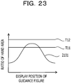
- FIG. 23 illustrates an example of threshold values with respect to the ratio of the hand area.
- a threshold value T11 indicates a low-frequency threshold value
- a threshold value T12 indicates a high-frequency threshold value. If the ratio of the hand area is equal to or higher than the threshold value T11 and the ratio rate of the hand area is lower than or equal to the threshold value T12, the position determination unit 513 determines that the display position of the guidance figure is suitable for capturing the image of the palm. If the ratio of the hand area is lower than the threshold value T11, or the ratio of the hand area is higher than the threshold value T12, the position determination unit 513 determines that the display position of the guidance figure is not suitable for capturing the image of the palm.
- the position determination unit 513 may omit the determination using the threshold value T12 and determine that the display position of the guidance figure is suitable for capturing the image of the palm.
- step 714 in FIG. 7 it is possible for the change unit 514 to change the shape or the display position of the guidance figure that is represented by the guidance information 521. For example, if the guidance figure includes a mark that indicates the position to be in contact with a finger and a movement area that indicates an area in which the mark moves, the change unit 514 moves the mark by a predetermined amount in the movement area so as to change the guidance figure.
- FIGs. 24A and 24B illustrate an example of the guidance figure including a mark and a movement area.
- FIG. 24A illustrates an example of the guidance figure including a movement area having a polygonal line shape.
- the guidance figure in FIG. 24A includes a mark 612-1 and a mark 612-2, and a movement area 2411-1 and a movement area 2411-2.
- the shapes of the movement area 2411-1 and the movement area 2411-2 may be the other shapes, which are combinations of a plurality of guide rails extending in the up-and-down and the left-and-right directions.
- a movement area 2401 having a polygonal line shape represents an area produced by enlarging the movement area 2411-1 or the movement area 2411-2, and a mark 2402 that moves in the movement area 2401 corresponds to a mark 612-1 or a mark 612-2.
- the change unit 514 moves the mark 2402 in accordance with the shape of the movement area 2401 by a predetermined amount so as to prompt the user to change the contact position of the finger.
- FIG. 24B illustrates an example of the guidance figure that includes a movement area having a curve shape.
- the guidance figure in FIG. 24B includes the mark 612-1 and the mark 612-2, and a movement area 2431-1 and a movement area 2431-2.
- the shape of the movement area 2431-1 and the movement area 2431-2 may be circular or elliptical.
- the curve-shaped movement area 2421 indicates an enlarged area of the movement area 2431-1 or the movement area 2431-2, and a mark 2422 that moves in the movement area 2421 corresponds to the mark 612-1 or the mark 612-2.
- the change unit 514 moves the mark 2422 in accordance with the shape of the movement area 2421 by a predetermined amount so as to prompt the user to change the contact position of the finger.
- FIG. 25 illustrates an example of a change in the contact position of the finger when the guidance figure in FIG. 24 is used.
- the display positions of those marks are changed and the distance between the mark 612-1 and the mark 612-2 is also changed.
- the contact position of the finger of the user and the shape of the hand 613 are changed, and thus the distance D between the sensor 502 and the palm is also changed.
- the display positions of the mark 612-1 and the mark 612-2 that are suitable for capturing the image of the palm are determined, and the optimum guidance information 524 is generated.
- the guidance figure does not have to include a movement area and may include only the mark 612-1 and the mark 612-2. Instead of the change unit 514 determining the movement quantity of the mark 612-1 and the mark 612-2, it is possible for the user to determine the movement quantity of those marks.
- step 714 the user moves the contact position of the two respective fingers having in contact with the mark 612-1 and the mark 612-2 by a predetermined amount, and the change unit 514 changes the display positions of the mark 612-1 and the mark 612-2 in accordance with the movement of the contact positions.
- the change unit 514 changes the display positions of the mark 612-1 and the mark 612-2 in accordance with the movement of the contact positions.
- the guidance figures do not have to include the mark 612-1 and the mark 612-2 and may be figures, such as rectangles, circles, or the like that indicate the target areas to be in contact with the two respective fingers.
- the change unit 514 changes the shapes or the display positions of the guidance figures, and the user moves the contact positions of the two respective fingers on the screen in the changed guidance figures.
- FIG. 26 is a flowchart illustrating an example of the authentication processing performed by the biometric authentication apparatus 301 in FIG. 5 .
- the display unit 311 displays the guidance figures represented by the optimum guidance information 524 on the screen (step 2601), and the detection unit 312 detects the contact state in which the two fingers of a person to be authenticated are in contact with the two respective points in the target area (step 2602).
- the imaging unit 313 captures the image of the palm in the detected contact state to obtain the biometric image 525 (step 2603).
- the biometric information detection unit 503 detects the biometric information 526 from the biometric image 525 (step 2604).
- the authentication unit 315 calculates the similarity between the biometric information 526 and the registration biometric information 527 (step 2605) and compares the similarity with a threshold value (step 2606).
- step 2606 determines as an authentication success (step 2607), and the display unit 311 displays an authentication result indicating the authentication success (step 2608).
- step 2606 determines as an authentication failure (step 2609), and the display unit 311 displays an authentication result indicating an authentication failure (step 2608).
- the guidance figures are displayed in accordance with the optimum guidance information 524 generated by the registration processing in FIG. 7 , and the image of the palm is captured in a state in which the distance D between the sensor 502 and the palm is suitable, and thus it is possible to obtain a clear biometric image of a person to be authenticated. Accordingly, the precision of the biometric information detected from the biometric image is improved, and the authentication precision of the biometric authentication using the biometric information is improved.
- the configurations of the biometric authentication apparatus 301 in FIG. 3 and FIG. 5 are only examples, and a part of the components may be omitted or changed in accordance with the application or the condition of the biometric authentication apparatus 301.
- the biometric authentication apparatus 301 in FIG. 5 if the determination on the display positions of the guidance figures is not performed, it is possible to omit the position determination unit 513. If the distance between the sensor 502 and the palm is measured using a distance sensor, it is possible to omit the feature detection unit 511.
- the biometric authentication apparatus 301 does not have to be a mobile terminal device and may be an information processing apparatus that performs logon control or entrance and exit management, an ATM, or the like.
- FIG. 4 , FIG. 7 , FIG. 8 , FIG. 12 , FIG. 22 , and FIG. 26 are only examples, and a part of the processing may be omitted or changed in accordance with the configuration and the condition of the biometric authentication apparatus 301.
- the registration processing in FIG. 7 if the determination of the display positions of the guidance figures is not performed, it is possible to omit the processing of step 706. If the distance between the sensor 502 and the palm is measured by using a distance sensor, it is possible to omit the processing of step 703 and step 704.
- the feature detection unit 511 may converts the image in a specific area into signals in the spatial frequency domain using the other transformation, such as the wavelet transformation, or the like instead of FFT.
- the biometric authentication apparatus 301 it is possible for the biometric authentication apparatus 301 to perform the determination of the distance D between the sensor 502 and the palm and the determination of the display positions of the guidance figures in the same manner as the registration processing. In this case, before the processing in step 2601, the same processing as the processing of step 701 to step 707 and step 714 is performed.
- the guidance figures in FIG. 1 , FIG. 2 , FIG. 6 , FIG. 18 , FIG. 19 , FIG. 24 , and FIG. 25 are only examples, and the shapes of the guidance figures may be the other shapes.
- the specific area in FIG. 9 is only an example, and the shape of the specific area may be the other shape.
- the conversion result of the specific areas in FIG. 10 and FIG. 11 are only examples, and the conversion result of the specific area changes in accordance with the determination biometric image 522.
- the distributions of pixel values in FIG. 13 to FIG. 16 are only examples, and the distribution of pixel values changes in accordance with the determination biometric image 522.
- the characteristic information of the imaging device in FIG. 17 is only an example, and the characteristic information of the imaging device changes in accordance with the optical characteristic of the imaging unit 313.
- the biometric image in FIG. 20 is only an example, and the biometric image changes in accordance with the position of the palm.
- the ratios of the hand areas in FIG. 21 and FIG. 23 are only examples and change in accordance with the determination biometric image 522.
- the biometric authentication apparatus 301 may perform the biometric authentication using the other biometric images instead of the biometric image of the hand.
- FIG. 27 illustrates an example of the configuration of an information processing apparatus (computer) to be used for the biometric authentication apparatus 301 in FIG. 3 and FIG. 5 .
- the information processing apparatus in FIG. 27 includes a central processing unit (CPU) 2701, a memory 2702, an input device 2703, an output device 2704, an auxiliary storage device 2705, a medium drive device 2706, and a network connection device 2707. These components are mutually connected by a bus 2708.
- the sensor 502 in FIG. 5 may be connected to the bus 2708.
- the memory 2702 is a semiconductor memory, for example, a read only memory (ROM), a random access memory (RAM), a flash memory, or the like and stores the program and the data used for the processing. It is possible to use the memory 2702 as the storage unit 504 in FIG. 5 .
- the CPU 2701 executes the program, for example, using the memory 2702 so as to operate as the determination unit 314 and the authentication unit 315 in FIG. 3 and FIG. 5 .
- the CPU 2701 executes the program using the memory 2702 so as to operate as the biometric information detection unit 503, the feature detection unit 511, the distance determination unit 512, the position determination unit 513, and the change unit 514 in FIG. 5 .
- the input device 2703 is, for example, a keyboard, a pointing device, or the like and is used for inputting an instruction or information from an operator or a user.
- the output device 2704 is, for example, a display device, a printer, a speaker, or the like and is used for inquiring of the operator or the user or outputting a processing result.
- the touch panel 501 in FIG. 3 corresponds to a combination of the input device 2703 and the output device 2704, and it is possible to use the output device 2704 for the display unit 311.
- the processing result may be the authentication result.
- the auxiliary storage device 2705 is, for example, a magnetic disk device, an optical disc device, a magneto-optical disk device, a tape device, or the like.
- the auxiliary storage device 2705 may be a flash memory or a hard disk drive. If the information processing apparatus is a mobile terminal device, it is possible to use a flash memory as the auxiliary storage device 2705. It is possible for the information processing apparatus to store the program and the data in the auxiliary storage device 2705, and load them into the memory 2702 to use them. It is possible to use the auxiliary storage device 2705 as the storage unit 504 in FIG. 5 .
- the medium drive device 2706 drives a portable recording medium 2709 and accesses the recording contents thereof.
- the portable recording medium 2709 may be a memory device, a flexible disk, an optical disc, a magneto-optical disk, or the like.
- the portable recording medium 2709 may be a Compact Disk read only memory (CD-ROM), a digital versatile disk (DVD), a Universal Serial Bus (USB) memory, or the like. If the information processing apparatus is a mobile terminal device, it is possible to use a memory card for the portable recording medium 2709. It is possible for the operator or the user to store the program and the data in the portable recording medium 2709 and load them into the memory 2702 to use them.
- a computer-readable recording medium that stores the program and the data to be used for the processing is a physical (non-transitory) recording medium, such as the memory 2702, the auxiliary storage device 2705, or the portable recording medium 2709.
- the network connection device 2707 is a communication interface circuit that is connected to a communication network, such as a local area network, a wide area network, or the like, and performs data conversion involved in communication. It is possible for the information processing apparatus to receive the program and the data from an external device via the network connection device 2707 and load them into the memory 2702 to use them.
- a communication network such as a local area network, a wide area network, or the like
- the information processing apparatus does not have to include all the components in FIG. 27 , and it is possible to omit a part of the components in accordance with the application or the conditions. For example, if the information processing apparatus does not use the portable recording medium 2709 or the communication network, it is possible to omit the medium drive device 2706 or the network connection device 2707.
- the information processing apparatus may include a telephone communication device, such as a microphone and a speaker.
Applications Claiming Priority (1)
| Application Number | Priority Date | Filing Date | Title |
|---|---|---|---|
| JP2018013203A JP6988523B2 (ja) | 2018-01-30 | 2018-01-30 | 生体認証装置、生体認証プログラム、及び生体認証方法 |
Publications (2)
| Publication Number | Publication Date |
|---|---|
| EP3518144A1 true EP3518144A1 (fr) | 2019-07-31 |
| EP3518144B1 EP3518144B1 (fr) | 2023-11-08 |
Family
ID=65234495
Family Applications (1)
| Application Number | Title | Priority Date | Filing Date |
|---|---|---|---|
| EP19153703.4A Active EP3518144B1 (fr) | 2018-01-30 | 2019-01-25 | Appareil d'authentification biométrique et procédé d'authentification biométrique |
Country Status (3)
| Country | Link |
|---|---|
| US (1) | US10896250B2 (fr) |
| EP (1) | EP3518144B1 (fr) |
| JP (1) | JP6988523B2 (fr) |
Families Citing this family (4)
| Publication number | Priority date | Publication date | Assignee | Title |
|---|---|---|---|---|
| CN112804937A (zh) * | 2018-10-01 | 2021-05-14 | 雷诺兹·德尔加多 | 在生物识别中的高频qrs |
| WO2021113876A1 (fr) | 2019-12-06 | 2021-06-10 | Aveva Software, Llc | Système intelligent et autonome d'assistance à la prise de décision et serveur |
| WO2023233943A1 (fr) * | 2022-05-31 | 2023-12-07 | 日本電気株式会社 | Système de photographie et procédé de photographie |
| CN116994344A (zh) * | 2022-07-18 | 2023-11-03 | 腾讯科技(深圳)有限公司 | 刷掌验证的引导方法、装置、终端、存储介质及程序产品 |
Citations (8)
| Publication number | Priority date | Publication date | Assignee | Title |
|---|---|---|---|---|
| JP2010211579A (ja) | 2009-03-11 | 2010-09-24 | Hitachi Omron Terminal Solutions Corp | 生体認証装置 |
| WO2012014304A1 (fr) | 2010-07-29 | 2012-02-02 | 富士通株式会社 | Dispositif et programme d'authentification biométrique |
| WO2013046365A1 (fr) | 2011-09-28 | 2013-04-04 | 富士通フロンテック株式会社 | Dispositif de guidage, dispositif d'acquisition d'informations biométriques et dispositif d'enregistrement |
| EP2830002A2 (fr) * | 2013-07-25 | 2015-01-28 | Fujitsu Limited | Dispositif de capture d'image, appareil d'authentification biométrique et procédé de capture d'image |
| EP3070631A1 (fr) * | 2015-03-16 | 2016-09-21 | Fujitsu Limited | Appareil terminal, procédé d'authentification biométrique et programme d'authentification biométrique |
| JP2016212636A (ja) | 2015-05-08 | 2016-12-15 | 富士通株式会社 | 生体撮影装置、生体撮影方法及び生体撮影プログラム |
| JP2017097574A (ja) | 2015-11-20 | 2017-06-01 | 富士通株式会社 | 情報処理装置、生体認証方法および生体認証プログラム |
| EP3200126A2 (fr) * | 2016-02-01 | 2017-08-02 | Fujitsu Limited | Dispositif de traitement d'informations biométriques, procédé de traitement d'informations biométriques, programme de traitement d'informations biométriques et dispositif de détection de distance |
Family Cites Families (5)
| Publication number | Priority date | Publication date | Assignee | Title |
|---|---|---|---|---|
| JP4704185B2 (ja) * | 2005-10-27 | 2011-06-15 | 富士通株式会社 | 生体認証システム及び生体認証方法 |
| US9251333B2 (en) * | 2013-08-29 | 2016-02-02 | Paypal, Inc. | Wearable user device authentication system |
| KR102091161B1 (ko) * | 2013-12-05 | 2020-03-19 | 엘지전자 주식회사 | 이동 단말기 및 그것의 제어방법 |
| JP2016194799A (ja) * | 2015-03-31 | 2016-11-17 | 富士通株式会社 | 画像解析装置及び画像解析方法 |
| KR20180066522A (ko) * | 2016-12-09 | 2018-06-19 | 엘지전자 주식회사 | 이동 단말기 및 그 제어 방법 |
-
2018
- 2018-01-30 JP JP2018013203A patent/JP6988523B2/ja active Active
-
2019
- 2019-01-25 EP EP19153703.4A patent/EP3518144B1/fr active Active
- 2019-01-28 US US16/258,805 patent/US10896250B2/en active Active
Patent Citations (10)
| Publication number | Priority date | Publication date | Assignee | Title |
|---|---|---|---|---|
| JP2010211579A (ja) | 2009-03-11 | 2010-09-24 | Hitachi Omron Terminal Solutions Corp | 生体認証装置 |
| WO2012014304A1 (fr) | 2010-07-29 | 2012-02-02 | 富士通株式会社 | Dispositif et programme d'authentification biométrique |
| WO2013046365A1 (fr) | 2011-09-28 | 2013-04-04 | 富士通フロンテック株式会社 | Dispositif de guidage, dispositif d'acquisition d'informations biométriques et dispositif d'enregistrement |
| EP2830002A2 (fr) * | 2013-07-25 | 2015-01-28 | Fujitsu Limited | Dispositif de capture d'image, appareil d'authentification biométrique et procédé de capture d'image |
| EP3070631A1 (fr) * | 2015-03-16 | 2016-09-21 | Fujitsu Limited | Appareil terminal, procédé d'authentification biométrique et programme d'authentification biométrique |
| JP2016173669A (ja) | 2015-03-16 | 2016-09-29 | 富士通株式会社 | 端末装置、生体認証プログラム及び生体認証方法 |
| JP2016212636A (ja) | 2015-05-08 | 2016-12-15 | 富士通株式会社 | 生体撮影装置、生体撮影方法及び生体撮影プログラム |
| JP2017097574A (ja) | 2015-11-20 | 2017-06-01 | 富士通株式会社 | 情報処理装置、生体認証方法および生体認証プログラム |
| EP3200126A2 (fr) * | 2016-02-01 | 2017-08-02 | Fujitsu Limited | Dispositif de traitement d'informations biométriques, procédé de traitement d'informations biométriques, programme de traitement d'informations biométriques et dispositif de détection de distance |
| JP2017136136A (ja) | 2016-02-01 | 2017-08-10 | 富士通株式会社 | 生体情報処理装置、生体情報処理方法、生体情報処理プログラム、および距離検知装置 |
Also Published As
| Publication number | Publication date |
|---|---|
| EP3518144B1 (fr) | 2023-11-08 |
| US10896250B2 (en) | 2021-01-19 |
| US20190236252A1 (en) | 2019-08-01 |
| JP2019133287A (ja) | 2019-08-08 |
| JP6988523B2 (ja) | 2022-01-05 |
Similar Documents
| Publication | Publication Date | Title |
|---|---|---|
| EP3518144B1 (fr) | Appareil d'authentification biométrique et procédé d'authentification biométrique | |
| US9349035B1 (en) | Multi-factor authentication sensor for providing improved identification | |
| US8077935B2 (en) | Methods and apparatus for acquiring a swiped fingerprint image | |
| US20160140379A1 (en) | Improvements in or relating to user authentication | |
| US10310675B2 (en) | User interface apparatus and control method | |
| KR101603469B1 (ko) | 생체 인증 장치, 생체 인증 방법 및 생체 인증용 컴퓨터 프로그램 | |
| WO2019151368A1 (fr) | Dispositif, système et procédé d'authentification biométrique et support d'enregistrement | |
| US9880634B2 (en) | Gesture input apparatus, gesture input method, and program for wearable terminal | |
| US10586031B2 (en) | Biometric authentication of a user | |
| JP2016212636A (ja) | 生体撮影装置、生体撮影方法及び生体撮影プログラム | |
| KR20130133223A (ko) | 바이오키네마틱 입력을 이용한 사용자 식별 | |
| JP2011191838A (ja) | 指静脈認証装置 | |
| US20140121528A1 (en) | Information processing apparatus, information processing method and program | |
| US20150213321A1 (en) | Information processing apparatus and body-part determining method | |
| KR20150055342A (ko) | 지문 인증 방법과 이를 수행하는 지문 인증 장치 및 이동 단말기 | |
| Hu et al. | Bare-fingers touch detection by the button's distortion in a projector–camera system | |
| JP2016081116A (ja) | 生体情報補正装置、生体情報補正方法及び生体情報補正用コンピュータプログラム | |
| US20170091521A1 (en) | Secure visual feedback for fingerprint sensing | |
| CN111164543B (zh) | 控制电子设备的方法 | |
| US20170061191A1 (en) | Fingerprint authentication | |
| WO2017063763A1 (fr) | Authentification biométrique sécurisée | |
| US10635799B2 (en) | Biometric authentication apparatus, biometric authentication method, and non-transitory computer-readable storage medium for storing program for biometric authentication | |
| EP3671538A1 (fr) | Appareil d'authentification biométrique et méthode d'authentification biométrique | |
| US20200285724A1 (en) | Biometric authentication device, biometric authentication system, and computer program product | |
| JP5768441B2 (ja) | 生体情報取得装置、生体情報取得方法、および生体情報取得プログラム |
Legal Events
| Date | Code | Title | Description |
|---|---|---|---|
| PUAI | Public reference made under article 153(3) epc to a published international application that has entered the european phase |
Free format text: ORIGINAL CODE: 0009012 |
|
| STAA | Information on the status of an ep patent application or granted ep patent |
Free format text: STATUS: THE APPLICATION HAS BEEN PUBLISHED |
|
| AK | Designated contracting states |
Kind code of ref document: A1 Designated state(s): AL AT BE BG CH CY CZ DE DK EE ES FI FR GB GR HR HU IE IS IT LI LT LU LV MC MK MT NL NO PL PT RO RS SE SI SK SM TR |
|
| AX | Request for extension of the european patent |
Extension state: BA ME |
|
| STAA | Information on the status of an ep patent application or granted ep patent |
Free format text: STATUS: REQUEST FOR EXAMINATION WAS MADE |
|
| 17P | Request for examination filed |
Effective date: 20200120 |
|
| RBV | Designated contracting states (corrected) |
Designated state(s): AL AT BE BG CH CY CZ DE DK EE ES FI FR GB GR HR HU IE IS IT LI LT LU LV MC MK MT NL NO PL PT RO RS SE SI SK SM TR |
|
| STAA | Information on the status of an ep patent application or granted ep patent |
Free format text: STATUS: EXAMINATION IS IN PROGRESS |
|
| 17Q | First examination report despatched |
Effective date: 20210324 |
|
| REG | Reference to a national code |
Ref document number: 602019040903 Country of ref document: DE Ref country code: DE Ref legal event code: R079 Free format text: PREVIOUS MAIN CLASS: G06K0009000000 Ipc: G06V0040145000 |
|
| GRAP | Despatch of communication of intention to grant a patent |
Free format text: ORIGINAL CODE: EPIDOSNIGR1 |
|
| STAA | Information on the status of an ep patent application or granted ep patent |
Free format text: STATUS: GRANT OF PATENT IS INTENDED |
|
| RIC1 | Information provided on ipc code assigned before grant |
Ipc: G06V 40/60 20220101ALI20230628BHEP Ipc: G06V 40/145 20220101AFI20230628BHEP |
|
| INTG | Intention to grant announced |
Effective date: 20230713 |
|
| GRAS | Grant fee paid |
Free format text: ORIGINAL CODE: EPIDOSNIGR3 |
|
| GRAA | (expected) grant |
Free format text: ORIGINAL CODE: 0009210 |
|
| STAA | Information on the status of an ep patent application or granted ep patent |
Free format text: STATUS: THE PATENT HAS BEEN GRANTED |
|
| AK | Designated contracting states |
Kind code of ref document: B1 Designated state(s): AL AT BE BG CH CY CZ DE DK EE ES FI FR GB GR HR HU IE IS IT LI LT LU LV MC MK MT NL NO PL PT RO RS SE SI SK SM TR |
|
| REG | Reference to a national code |
Ref country code: GB Ref legal event code: FG4D |
|
| REG | Reference to a national code |
Ref country code: CH Ref legal event code: EP |
|
| REG | Reference to a national code |
Ref country code: DE Ref legal event code: R096 Ref document number: 602019040903 Country of ref document: DE |
|
| REG | Reference to a national code |
Ref country code: IE Ref legal event code: FG4D |
|
| REG | Reference to a national code |
Ref country code: LT Ref legal event code: MG9D |
|
| REG | Reference to a national code |
Ref country code: NL Ref legal event code: MP Effective date: 20231108 |
|
| PG25 | Lapsed in a contracting state [announced via postgrant information from national office to epo] |
Ref country code: GR Free format text: LAPSE BECAUSE OF FAILURE TO SUBMIT A TRANSLATION OF THE DESCRIPTION OR TO PAY THE FEE WITHIN THE PRESCRIBED TIME-LIMIT Effective date: 20240209 |
|
| PG25 | Lapsed in a contracting state [announced via postgrant information from national office to epo] |
Ref country code: IS Free format text: LAPSE BECAUSE OF FAILURE TO SUBMIT A TRANSLATION OF THE DESCRIPTION OR TO PAY THE FEE WITHIN THE PRESCRIBED TIME-LIMIT Effective date: 20240308 |
|
| PG25 | Lapsed in a contracting state [announced via postgrant information from national office to epo] |
Ref country code: LT Free format text: LAPSE BECAUSE OF FAILURE TO SUBMIT A TRANSLATION OF THE DESCRIPTION OR TO PAY THE FEE WITHIN THE PRESCRIBED TIME-LIMIT Effective date: 20231108 |
|
| REG | Reference to a national code |
Ref country code: AT Ref legal event code: MK05 Ref document number: 1630346 Country of ref document: AT Kind code of ref document: T Effective date: 20231108 |
|
| PG25 | Lapsed in a contracting state [announced via postgrant information from national office to epo] |
Ref country code: NL Free format text: LAPSE BECAUSE OF FAILURE TO SUBMIT A TRANSLATION OF THE DESCRIPTION OR TO PAY THE FEE WITHIN THE PRESCRIBED TIME-LIMIT Effective date: 20231108 |
|
| PG25 | Lapsed in a contracting state [announced via postgrant information from national office to epo] |
Ref country code: AT Free format text: LAPSE BECAUSE OF FAILURE TO SUBMIT A TRANSLATION OF THE DESCRIPTION OR TO PAY THE FEE WITHIN THE PRESCRIBED TIME-LIMIT Effective date: 20231108 |