EP3517792A1 - Système de fixation de limitation de compression - Google Patents
Système de fixation de limitation de compression Download PDFInfo
- Publication number
- EP3517792A1 EP3517792A1 EP19153735.6A EP19153735A EP3517792A1 EP 3517792 A1 EP3517792 A1 EP 3517792A1 EP 19153735 A EP19153735 A EP 19153735A EP 3517792 A1 EP3517792 A1 EP 3517792A1
- Authority
- EP
- European Patent Office
- Prior art keywords
- spring element
- axial hub
- fastening system
- wall
- sleeve
- Prior art date
- Legal status (The legal status is an assumption and is not a legal conclusion. Google has not performed a legal analysis and makes no representation as to the accuracy of the status listed.)
- Withdrawn
Links
- 238000007906 compression Methods 0.000 title claims abstract description 46
- 230000006835 compression Effects 0.000 title claims abstract description 43
- 230000013011 mating Effects 0.000 claims abstract description 47
- 230000008878 coupling Effects 0.000 claims abstract description 40
- 238000010168 coupling process Methods 0.000 claims abstract description 40
- 238000005859 coupling reaction Methods 0.000 claims abstract description 40
- 238000000034 method Methods 0.000 claims description 14
- 230000014759 maintenance of location Effects 0.000 claims description 9
- 230000007797 corrosion Effects 0.000 description 4
- 238000005260 corrosion Methods 0.000 description 4
- 239000000463 material Substances 0.000 description 4
- 238000004519 manufacturing process Methods 0.000 description 2
- 239000007769 metal material Substances 0.000 description 2
- 230000000717 retained effect Effects 0.000 description 2
- 239000007921 spray Substances 0.000 description 2
- 229910001220 stainless steel Inorganic materials 0.000 description 2
- 239000010935 stainless steel Substances 0.000 description 2
- 230000000712 assembly Effects 0.000 description 1
- 238000000429 assembly Methods 0.000 description 1
- 230000004323 axial length Effects 0.000 description 1
- 238000010276 construction Methods 0.000 description 1
- 239000002537 cosmetic Substances 0.000 description 1
- 230000005489 elastic deformation Effects 0.000 description 1
- 230000008676 import Effects 0.000 description 1
- 238000003780 insertion Methods 0.000 description 1
- 230000037431 insertion Effects 0.000 description 1
- 238000009434 installation Methods 0.000 description 1
- 238000012986 modification Methods 0.000 description 1
- 230000004048 modification Effects 0.000 description 1
- 230000000087 stabilizing effect Effects 0.000 description 1
Images


Classifications
-
- F—MECHANICAL ENGINEERING; LIGHTING; HEATING; WEAPONS; BLASTING
- F16—ENGINEERING ELEMENTS AND UNITS; GENERAL MEASURES FOR PRODUCING AND MAINTAINING EFFECTIVE FUNCTIONING OF MACHINES OR INSTALLATIONS; THERMAL INSULATION IN GENERAL
- F16B—DEVICES FOR FASTENING OR SECURING CONSTRUCTIONAL ELEMENTS OR MACHINE PARTS TOGETHER, e.g. NAILS, BOLTS, CIRCLIPS, CLAMPS, CLIPS OR WEDGES; JOINTS OR JOINTING
- F16B39/00—Locking of screws, bolts or nuts
- F16B39/22—Locking of screws, bolts or nuts in which the locking takes place during screwing down or tightening
- F16B39/24—Locking of screws, bolts or nuts in which the locking takes place during screwing down or tightening by means of washers, spring washers, or resilient plates that lock against the object
- F16B39/26—Locking of screws, bolts or nuts in which the locking takes place during screwing down or tightening by means of washers, spring washers, or resilient plates that lock against the object with spring washers fastened to the nut or bolt-head
-
- B—PERFORMING OPERATIONS; TRANSPORTING
- B60—VEHICLES IN GENERAL
- B60R—VEHICLES, VEHICLE FITTINGS, OR VEHICLE PARTS, NOT OTHERWISE PROVIDED FOR
- B60R13/00—Elements for body-finishing, identifying, or decorating; Arrangements or adaptations for advertising purposes
- B60R13/08—Insulating elements, e.g. for sound insulation
-
- F—MECHANICAL ENGINEERING; LIGHTING; HEATING; WEAPONS; BLASTING
- F16—ENGINEERING ELEMENTS AND UNITS; GENERAL MEASURES FOR PRODUCING AND MAINTAINING EFFECTIVE FUNCTIONING OF MACHINES OR INSTALLATIONS; THERMAL INSULATION IN GENERAL
- F16B—DEVICES FOR FASTENING OR SECURING CONSTRUCTIONAL ELEMENTS OR MACHINE PARTS TOGETHER, e.g. NAILS, BOLTS, CIRCLIPS, CLAMPS, CLIPS OR WEDGES; JOINTS OR JOINTING
- F16B29/00—Screwed connection with deformation of nut or auxiliary member while fastening
-
- F—MECHANICAL ENGINEERING; LIGHTING; HEATING; WEAPONS; BLASTING
- F16—ENGINEERING ELEMENTS AND UNITS; GENERAL MEASURES FOR PRODUCING AND MAINTAINING EFFECTIVE FUNCTIONING OF MACHINES OR INSTALLATIONS; THERMAL INSULATION IN GENERAL
- F16B—DEVICES FOR FASTENING OR SECURING CONSTRUCTIONAL ELEMENTS OR MACHINE PARTS TOGETHER, e.g. NAILS, BOLTS, CIRCLIPS, CLAMPS, CLIPS OR WEDGES; JOINTS OR JOINTING
- F16B43/00—Washers or equivalent devices; Other devices for supporting bolt-heads or nuts
-
- F—MECHANICAL ENGINEERING; LIGHTING; HEATING; WEAPONS; BLASTING
- F16—ENGINEERING ELEMENTS AND UNITS; GENERAL MEASURES FOR PRODUCING AND MAINTAINING EFFECTIVE FUNCTIONING OF MACHINES OR INSTALLATIONS; THERMAL INSULATION IN GENERAL
- F16B—DEVICES FOR FASTENING OR SECURING CONSTRUCTIONAL ELEMENTS OR MACHINE PARTS TOGETHER, e.g. NAILS, BOLTS, CIRCLIPS, CLAMPS, CLIPS OR WEDGES; JOINTS OR JOINTING
- F16B5/00—Joining sheets or plates, e.g. panels, to one another or to strips or bars parallel to them
- F16B5/02—Joining sheets or plates, e.g. panels, to one another or to strips or bars parallel to them by means of fastening members using screw-thread
- F16B5/0241—Joining sheets or plates, e.g. panels, to one another or to strips or bars parallel to them by means of fastening members using screw-thread with the possibility for the connection to absorb deformation, e.g. thermal or vibrational
-
- F—MECHANICAL ENGINEERING; LIGHTING; HEATING; WEAPONS; BLASTING
- F16—ENGINEERING ELEMENTS AND UNITS; GENERAL MEASURES FOR PRODUCING AND MAINTAINING EFFECTIVE FUNCTIONING OF MACHINES OR INSTALLATIONS; THERMAL INSULATION IN GENERAL
- F16B—DEVICES FOR FASTENING OR SECURING CONSTRUCTIONAL ELEMENTS OR MACHINE PARTS TOGETHER, e.g. NAILS, BOLTS, CIRCLIPS, CLAMPS, CLIPS OR WEDGES; JOINTS OR JOINTING
- F16B5/00—Joining sheets or plates, e.g. panels, to one another or to strips or bars parallel to them
- F16B5/02—Joining sheets or plates, e.g. panels, to one another or to strips or bars parallel to them by means of fastening members using screw-thread
- F16B5/0258—Joining sheets or plates, e.g. panels, to one another or to strips or bars parallel to them by means of fastening members using screw-thread using resiliently deformable sleeves, grommets or inserts
-
- F—MECHANICAL ENGINEERING; LIGHTING; HEATING; WEAPONS; BLASTING
- F16—ENGINEERING ELEMENTS AND UNITS; GENERAL MEASURES FOR PRODUCING AND MAINTAINING EFFECTIVE FUNCTIONING OF MACHINES OR INSTALLATIONS; THERMAL INSULATION IN GENERAL
- F16B—DEVICES FOR FASTENING OR SECURING CONSTRUCTIONAL ELEMENTS OR MACHINE PARTS TOGETHER, e.g. NAILS, BOLTS, CIRCLIPS, CLAMPS, CLIPS OR WEDGES; JOINTS OR JOINTING
- F16B5/00—Joining sheets or plates, e.g. panels, to one another or to strips or bars parallel to them
- F16B5/02—Joining sheets or plates, e.g. panels, to one another or to strips or bars parallel to them by means of fastening members using screw-thread
- F16B5/0266—Joining sheets or plates, e.g. panels, to one another or to strips or bars parallel to them by means of fastening members using screw-thread using springs
-
- B—PERFORMING OPERATIONS; TRANSPORTING
- B60—VEHICLES IN GENERAL
- B60R—VEHICLES, VEHICLE FITTINGS, OR VEHICLE PARTS, NOT OTHERWISE PROVIDED FOR
- B60R13/00—Elements for body-finishing, identifying, or decorating; Arrangements or adaptations for advertising purposes
- B60R13/08—Insulating elements, e.g. for sound insulation
- B60R2013/0807—Arrangements of fasteners or clips specially adapted therefore
Definitions
- connection assemblies and, more particularly, to fastening systems that are configured to receive an elongated fastening element through a component so as to apply a relatively light load to the component while the fastening element establishes a secure connection with an underlying mating structure.
- a threaded member may be connected in place relative to a surface of a panel or other such component by extending an elongated male fastening element (for example, a threaded bolt) through a hole in the component and engaging a mating structure at a far side of the component.
- the mating structure may be a rotatable nut or a component such as a panel or the like with a female opening for receipt and engagement with the fastening element.
- a heat shield or a similar component may be coupled to an automotive engine or other heat-generating element.
- the vibrations from the engine, as well as differing thermal expansion coefficients, may result in the fastened component being gradually damaged. This damage may cause a loosening of the connection between the component and the engine over time.
- supporting sleeve inserts may be used to act as compression limiters at the interior of the opening in the component. Such sleeve inserts may be useful in preventing over compression of the fastened component. A sleeve insert also may be used to maintain a gap between the fastened component and the underlying mating structure. While sleeve inserts may provide a useful function, such elements do not provide stabilizing load across the upper surface of the component during connection. An independent cylindrical sleeve also typically requires a separate installation step at the time of connection.
- a fastening system configured to securely couple a fastened component to a mating structure.
- the fastening system comprises a fastener, a compression limiting sleeve, and a spring element.
- the fastener has a shaft.
- the compression limiting sleeve has an axial hub, a base, and a sleeve outer wall.
- the axial hub extends perpendicularly from the base and is configured to receive the shaft of the fastener.
- the sleeve outer wall extends from the base.
- the spring element has a central portion and a spring element outer wall. The central portion includes a central opening configured to receive the shaft of the fastener.
- the spring element outer wall extends from the central portion and includes a first annular portion and a second annular portion.
- the first annular portion is connected to the second annular portion.
- the first annular portion extends at a first angle with respect to a central axis of the spring element.
- the second annular portion extends at a second angle with respect to the central axis of the spring element. The first angle is different than the second angle.
- At least one of the compression limiting sleeve and the spring element may include at least one opening.
- the at least one opening may define a circular shape.
- the at least one opening may define an elongated slot.
- the elongated slot may be an open-ended slot.
- the sleeve outer wall and the spring element outer wall may each be configured to act as a spring when compressed.
- a distal end of the axial hub may extend proximate to the central portion of the spring element.
- the spring element may further comprise a lip radially extending from the spring element outer wall and defining an arcuate shape.
- a fastening system configured to securely couple a fastened component to a mating structure using a fastener having a shaft.
- the fastening system comprises a compression limiting sleeve and a spring element.
- the compression limiting sleeve has an axial hub, a base, and a sleeve outer wall.
- the axial hub extends perpendicularly from the base and is configured to receive the shaft of the fastener.
- the sleeve outer wall extends from the base.
- the spring element has a central portion and a spring element outer wall.
- the central portion includes a central opening and at least one coupling feature. The central opening is configured to receive the shaft of the fastener.
- the at least one coupling feature is configured to engage the axial hub of the compression limiting sleeve.
- the compression limiting sleeve is removably coupled to the spring element.
- the axial hub may define a hollow cylindrical shape and include a crimped distal end defining a larger outer diameter than a remainder of the axial hub.
- the at least one coupling feature may be configured to engage the crimped distal end of the axial hub.
- the at least one coupling feature may be at least one protrusion extending radially-inward from an inner surface of the central portion of the spring element, into the central opening of the spring element.
- the at least one coupling feature may be at least one engagement arm having a retention lip that is sized to engage the crimped distal end of the axial hub.
- At least one of the compression limiting sleeve and the spring element may include at least one opening.
- the at least one opening may define an open-ended slot.
- the spring element may further comprise a lip radially extending from the spring element outer wall and defining an arcuate shape.
- a method for assembling a fastening system onto a fastened component having an opening is provided.
- the fastening system may be configured to securely couple the fastened component to a mating structure and have a compression limiting sleeve and a spring element.
- the compression limiting sleeve may have an axial hub with an engagement portion.
- the spring element may have a central opening and at least one coupling feature.
- the method comprises inserting the axial hub of the compression limiting sleeve through the opening of the fastened component.
- the method further comprises placing the spring element over the axial hub on the fastened component.
- the method further comprises inserting the axial hub into the central opening of the spring element. While the axial hub is inserted into the central opening of the spring element, the engagement portion of the axial hub engages the at least one coupling feature of the spring element, thereby removably coupling the compression limiting sleeve to the spring element.
- the engagement portion of the axial hub may be a crimped distal end of the axial hub.
- the at least one coupling feature may be at least one protrusion extending into the central opening that is sized to engage the engagement portion of the axial hub.
- the at least one coupling feature may be at least one engagement arm including a retention lip that is sized to engage the engagement portion of the axial hub.
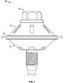
- the fastening system 10 includes a compression limiting sleeve 12, a spring element 14, and a fastener 16.
- the fastening system 10 may be used to fasten a fastened component 18 to a mating structure 20 (shown in FIG. 8 ) in an automotive setting.
- the fastening system 10 may be used to fasten a heat shield to a heat generating automotive engine component such as a manifold, an engine block, or any other desired component.
- the fastening system 10 may be used to couple other suitable components to other types of mating structures.
- the fastening system 10 may be used to provide a secure fastening between the fastened component 18 and the mating structure 20, while simultaneously ensuring that the fastened component 18 is stabilized relative to the mating structure 20 and preventing an over-compression of the fastened component 18.
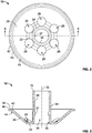
- the sleeve 12 comprises a base 22, an axial hub 24, an outer wall 26, and a plurality of openings 28.
- the base 22 defines a substantially flat, annular shape surrounding a proximal end 30 of the axial hub 24.
- the axial hub 24 extends substantially perpendicularly from the base 22 along a central axis 32 of the sleeve 12.
- the axial hub 24 defines a hollow cylindrical shape having a central axial passageway 34.
- the central axial passageway 34 is sized to receive a shaft 36 of the fastener 16, as shown in FIGS. 7 and 8 .
- the axial hub 24 may further include a coupling feature 37 extending radially inward from an inner surface 38 of the axial hub 24.
- the coupling feature 37 may be a detent or other type of radially-extending protrusion that may extend partially or fully around the circumference of the axial hub 24.
- the coupling feature 37 may be configured to removably engage a corresponding coupling recess 40 disposed on the shaft 36 of the fastener 16, thereby removably coupling the sleeve 12 to the fastener 16 prior to use, as also shown in FIGS. 7 and 8 .
- the axial hub 24 may be devoid of any protrusions on the inner surface 38, such that the axial hub 24 has a constant diameter throughout the axial length of the axial hub 24, as shown in FIG. 11 . Accordingly, in these instances, the fastener 16 may not include the coupling recess 40, as also shown in FIG. 11 .
- the outer wall 26 extends at an angle from an outer periphery of the base 22. Specifically, the outer wall 26 extends both radially outward and axially, in the same axial direction as the axial hub 24, away from the periphery of the base 22. As such, the outer wall 26 defines a generally annular bowl shape surrounding the base 22.
- the outer wall 26 further includes a lip 42 extending radially outward from a distal end 44 of the outer wall 26.
- the lip 42 defines a generally flat, annular shape surrounding the outer wall 26.
- the lip 42 includes an upper surface 45 and a rounded outer edge 46.
- the upper surface 45 is configured to contact the fastened component 18 when the fastening assembly 10 is coupled thereto.
- the rounded outer edge 46 is disposed on an outer periphery of the upper surface 45 and is configured to prevent the sleeve 12 from inadvertently deforming the fastened component 18 during use, as will be described below.
- the plurality of openings 28 are disposed circumferentially around the sleeve 12, surrounding the axial hub 24. Each opening 28 extends axially through the sleeve 12 through a portion of the base 22 and a portion of the outer wall 26.
- the openings 28 are configured to allow for foreign materials (e.g., spray, debris, moisture, etc.) to pass out of the fastening system 10 and/or evaporate. As such, the openings 28 may prevent or reduce a potential of galvanic corrosion during use.
- the outer wall 26 may act as a spring when it is compressed. As such, the openings 28 may reduce an effective spring constant of the outer wall 26, thereby reducing the corresponding spring force that the outer wall 26 is configured to impart on the fastened component 18 during use.
- each of the openings 28 defines a substantially circular shape.
- the openings 28 may alternatively define other shapes, such as, for example, radially-extending slots, semi-annular slots extending circumferentially around a portion of the sleeve 12, or any other suitable shape.
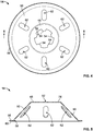
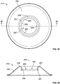
- the spring element 14 defines a generally dome-shaped structure having a central portion 48 and an outer wall 50.
- the central portion 48 defines a generally annular shape and includes a central opening 52.
- the central opening 52 may be sized to receive the shaft 36 of the fastener 16.
- a plurality of protrusions 54 may extend radially inward from the central portion 48, into the central opening 52.
- the protrusions 54 may be included to ensure a secure fit between the central opening 52 and the shaft 36 of the fastener 16 during use.
- the outer wall 50 extends at an angle from an outer periphery of the central portion 48. Specifically, the outer wall 50 extends both radially outward and axially away from the periphery of the central portion 48. As such, the outer wall 50 defines a generally frustoconical shape surrounding the central portion 48.
- the outer wall 50 includes a lip 56 extending radially outward from a distal end 58 of the outer wall 50.
- the lip 56 defines an annular shape surrounding the outer wall 50.
- the lip 56 further defines an arcuate shape having a convex surface 60 configured to contact the fastened component 18 during use. The arcuate shape of the lip 56, and specifically the convex surface 60, prevents and/or reduces inadvertent deformation of the fastened component 18 by the spring element 14 during use.
- the outer wall 50 further includes a plurality of openings 62 spaced evenly around the outer wall 50.
- Each of the openings 62 defines an elongated slot extending radially along a portion of the outer wall 50. Similar to the openings 28, the openings 62 are configured to allow for foreign materials (e.g., spray, debris, moisture, etc.) to pass out of the fastening system 10 and/or evaporate, thereby preventing or reducing the potential for galvanic corrosion during use.
- foreign materials e.g., spray, debris, moisture, etc.
- outer walls 26, 50 each include corresponding openings 28, 62, foreign materials may be allowed to pass out of the fastening system 10 regardless of the orientation of the fastening system 10.
- the outer wall 50 may similarly act like a spring when it is compressed.
- the openings 62 may similarly reduce an effective spring constant of the outer wall 50, thereby reducing the corresponding spring force that the outer wall 50 is configured to impart on the fastened component 18 during use.
- each of the openings 62 defines an elongated slot.
- the openings 62 may alternatively define other shapes, such as, for example, circular holes, semi-annular slots extending circumferentially around a portion of the spring element 14, or any other suitable shape.
- the spring element 14 may not include any openings, as shown in FIG. 6 .
- both the sleeve 12 and the spring element 14 may comprise a metal material.
- both the sleeve 12 and the spring element 14 may comprise 300 series stainless steel. Stainless steel may be used to further reduce or eliminate the risk of galvanic corrosion during use.
- the spring element 14 may be made of other suitable metallic or non-metallic materials, as desired for a given application.
- the axial hub 24 of the sleeve 12 may first be inserted through an opening 64 of the fastened component 18, and may be fed through the opening 64 until the lip 42 of the sleeve 12 comes into contact with a lower surface 66 of the fastened component 18. Then, the spring element 14 may be placed on an upper surface 68 of the fastened component 18, such that the lip 56 of the spring element 14 is in contact with the upper surface 68 and the dome shape of the spring element 14 covers the portion of the axial hub 24 extending through the opening 64. As illustrated in FIG.
- axial hub 24 when the spring element 14 is placed over the axial hub 24, a distal end 70 of the axial hub 24 extends to a location proximate a lower surface 71 of the central portion 48.
- the axial hub 24 is configured to robustly retain the shaft 36 of the fastener 16 in the axial direction during use.
- the shaft 36 of the fastener 16 may be inserted through the central opening 52 of the spring element 14 and through the axial hub 24 of the sleeve 12.
- a lower surface 72 of a head 73 of the fastener 16 eventually contacts an upper surface 74 of the central portion 48 of the spring element 14 (shown in FIG. 5 ), thereby impeding further insertion.
- the coupling feature 37 may removably engage the coupling recess 40 of the shaft 36.
- the fastener 16 may be removably coupled within the axial hub 24, and the sleeve 12, the spring element 14, the fastener 16, and the fastened component 18 may all be retained in engagement with each other.
- fastening system 10 including the sleeve 12, the spring element 14, and the fastener 16 may be assembled apart from the fastened component 18, in a similar manner as described above, to allow for convenient shipping or transporting of the fastening system 10 prior to use.
- the fastening assembly 10 may first be coupled to or assembled onto the fastened component 18, as described above. With the fastening assembly 10 arranged on the fastened component 18, a threaded portion 76 of the shaft 36 of the fastener 16 may be screwed into a corresponding threaded aperture 78 of the mating structure 20.
- the head 73 of the fastener 16 contacts the upper surface 74 of the central portion 48.
- the head 73 then presses the spring element 14 against the fastened component 18, which, in turn, presses the sleeve 12 against the mating structure 20.
- the outer wall 50 of the spring element 14 is axially compressed between the head 73 of the fastener 16 and the upper surface 68 of the fastened component 18.
- the outer wall 26 of the sleeve 12 is axially compressed between the lower surface 66 of the fastened component 18 and the mating structure 20.
- the outer walls 26, 50 of the sleeve 12 and the spring element 14 are axially compressed, the outer walls 26, 50 each undergo a slight elastic deformation, resulting in spring-like counterforces being applied by the outer walls 26, 50 onto the head 73, the fastened component 18, and the mating structure 20.
- the fastened component 18 is compressively engaged between the lip 42 of the sleeve 12 and the lip 56 of the spring element 14.
- the rounded edge 46 of the lip 42 may aid in preventing the sleeve 12 from inadvertently damaging the lower surface 66 of the fastened component 18 (see FIG. 7 ).
- the arcuate shape of the lip 56, and more specifically the convex surface 60 may prevent or reduce the spring element 14 from inadvertently damaging the upper surface 68 of the fastened component 18.
- FIGS. 7 and 8 as the head 73 of the fastener 16 is pulled toward the mating structure 20, the lower surface 71 of the central portion 48 of the spring element 14 eventually comes into contact with the distal end 70 of the axial hub 24. Once the lower surface 71 of the central portion 48 contacts the distal end 70 of the axial hub 24, the axial hub 24 prevents the head 73 of the fastener 16 from advancing farther toward the mating structure 20.
- any resultant forces caused by accidental over-tightening of the fastener 16 are transferred through the central portion 48 of the spring element 14, through the axial hub 24, through the base 22, and into mating structure 20.
- the compressive force applied to the fastened component 18 is limited, thereby preventing the fastened component 18 from being over-compressed and damaged by the sleeve 12 and/or the spring element 14.
- the spring element 14 may have a significantly thinner thickness than the sleeve 12. As such, the spring element 14 may have a significantly lower spring constant than the sleeve 12, and may thus compress significantly more than the sleeve 12 during use. Accordingly, a maximum compressive force exerted on the fastened component 18 can be accurately predetermined by determining the spring constant of the spring element 14 and controlling the size of an uncompressed gap 84 (shown in FIG. 7 ).
- the fastening system 10 provides a secure fastening between the fastened component 18 and the mating structure 20, while simultaneously ensuring that the fastened component 18 is stabilized relative to the mating structure 20 and preventing over-compression or inadvertent damage to the fastened component 18.
- both the outer wall 26 of the sleeve 12 and the outer wall 50 of the spring element 14 act like springs during use, the fastened component 18 is securely fastened to the mating structure 20 while simultaneously being substantially decoupled and/or protected from severe vibrations and stresses caused by differing thermal expansion coefficients between the fastened component 18 and the mating structure 20.
- the fastened component 18 may be decoupled and/or protected from the vibrations of the mating structure 20 or stresses caused by differing thermal expansion coefficients between the fastened component 18 and the mating structure 20.
- the fastening system 10 provides an improved connection between the fastened component 18 and the mating structure 20 that is more resistant to wear and/or damage than traditional rigid mountings, thereby preventing wear-induced loosening of the connection between the fastened component 18 and the mating structure 20.
- a spring element 114 is illustrated that may be used in place of the spring element 14.
- the spring element 114 is substantially similar to the spring element 14.
- similar elements will be labeled similarly in the 100 series (e.g., central portion 48 and central portion 148, central opening 52 and central opening 152, lip 56 and lip 156, etc.). Accordingly, the following description will be mainly directed toward the differences between the spring element 114 and the spring element 14.
- the spring element 114 similarly includes a central portion 148 having a central opening 152. However, as illustrated, the central portion 148 does not include a plurality of protrusions extending into the central opening 152. The lack of protrusions may reduce the complexity of the manufacturing process of the spring element 114, which may allow for a decrease in the time and cost of manufacturing.
- the spring element 114 also similarly includes an outer wall 150 having a lip 156 extending radially outward from a distal end 158 of the outer wall 150.
- the outer wall 150 further includes a first annular portion 151 and a second annular portion 153.
- the first annular portion 151 extends from the central portion 148 to the second annular portion 153 at a first angle with respect to a central axis 155 of the spring element 114.
- the second annular portion 153 extends from the first annular portion 151 to the lip 156 at a second angle with respect to the central axis 155 of the spring element 114.
- the first angle is significantly smaller than the second angle. Accordingly, the first annular portion 151 extends from the central portion 148 in a significantly more axial direction compared to the second annular portion 153, which extends from the first annular portion 151 in a significantly more radial direction.
- the different slopes of the first annular portion 151 and the second annular portion 153 provide increased axial clearance for the axial hub 24 due to the more axially-extending first annular portion 151, as shown in FIG. 11 , while simultaneously maintaining a low spring constant due to the more radially-extending second annular portion 153.
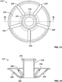
- the fastening system 210 similarly includes a compression limiting sleeve 212 and a spring element 214, and may similarly be used to couple the fastened component 18 to a mating structure, such as the mating structure 20 described above, with a fastener, such as the fastener 16.
- the fastening system 210 is substantially similar to the fastening system 10. As such, similar elements will be labeled similarly in the 200 series (e.g., sleeve 12 and sleeve 212, spring element 14 and spring element 214, axial hub 24 and axial hub 224, etc.). Accordingly, the following description will be mainly directed toward the differences between the fastening system 210 and the fastening system 10.
- the sleeve 212 may similarly include a base 222, an axial hub 224, and an outer wall 226.
- the axial hub 224 may include an engagement portion in the form of a crimped distal end 270.
- the crimped distal end 270 defines a larger outer diameter than the remainder of the axial hub 224.
- the outer wall 226 includes a plurality of radially-extending slots 228. The slots 228 each extend radially outward from the base 222 through the entire outer wall 226. As such, each slot 228 defines an open-ended slot.
- the slots 228 may allow for foreign materials to pass out of the fastening system 210 and/or evaporate, thus preventing or reducing the potential of galvanic corrosion during use.
- the slots 228 may also reduce the effective spring constant of the outer wall 226. Because the slots 228 are open-ended and extend radially through the entire outer wall 226, they may reduce the effective spring constant of the outer wall 226 by significantly more compared to the openings 28 of the outer wall 26.
- the spring element 214 includes a central portion 248, an outer wall 250, and a central opening 252 with a central axis 255 extending therethrough.
- the outer wall 250 is substantially the same as the outer wall 50.
- the central portion 248 is curved such that an upper surface 257 of the central portion 248 extends radially inward, toward the central axis 255 of the spring element 214, an inner surface 259 extends axially downward generally parallel to the central axis 255, and a lower surface 261 extends radially outward, away from the central axis 255.
- the inner surface 259 defines the central opening 252 of the spring element 214.
- the inner surface 259 may include a plurality of coupling features or protrusions 263. As illustrated, the inner surface 259 may include three, evenly-spaced protrusions 263. In some other instances, the inner surface 259 may include more or less than three protrusions 263, and the protrusions 263 may be evenly- or unevenly-spaced. The protrusions 263 may be sized to engage the crimped distal end 270 of the axial hub 224 when the fastening system 210 is assembled.
- the spring element 214 may be placed over the axial hub 224, such that the axial hub 224 is inserted into the central opening 252 of the spring element 214.
- the crimped distal end 270 of the axial hub 224 is sized to engage the protrusions 263 in a snap-thru manner, thereby removably coupling the axial hub 224 within the central opening 252.
- the fastened component 18 may be coupled to a mating structure, such as the mating structure 20, using a fastener, such as the fastener 16, as described above with reference to the fastening system 10.
- the head 73 of the fastener 16 may be sized to extend radially such that the lower surface 72 of the head 73 contacts the upper surface 257 of the central portion 248 as the fastener 16 is screwed into the mating structure 20.
- a washer (not shown) may be used to provide sufficient width to the head 73 of the fastener 16.
- any resultant forces caused by over tightening the fastener 16 are transferred through the axial hub 224, through the base 222, and directly into the mating structure, thereby preventing over compression of the fastened component 18 between the sleeve 212 and the spring element 214.
- the fastening system 210 is shown including another spring element 314.
- the spring element 314 is substantially similar to the spring element 214 discussed above. As such, similar elements will be labeled similarly in the 300 series, and the following description will be mainly directed toward the differences between the spring element 314 and the spring element 214.
- the spring element 314 includes a central portion 348 defining a central opening 352 and having an upper surface 357 and a plurality of coupling features or engagement arms 365.
- the spring element 314 includes five, evenly-spaced engagement arms 365.
- the spring element 314 may include more or less than five engagement arms 365, and the engagement arms 365 may be evenly or unevenly spaced.
- Each of the plurality of engagement arms 365 includes a retention lip 367 that is sized to engage the crimped distal end 270 of the axial hub 224.
- the crimped distal end 270 may contact the retention lips 367 of the engagement arms 365, thereby flexing the engagement arms 365 radially outward. Then, once the crimped distal end 270 passes the retention lips 367 of the engagement arms 365, the engagement arms 365 may snap back into place, thereby capturing the crimped distal end 270 and retaining the axial hub 224 within the central opening 352 of the spring element 314.
- the crimped distal end 270 of the axial hub 224 may be snap-fit through the central opening 352 of the spring element 314, and subsequently retained therein by the retention lips 367.
- the axial hub 224 may then be removed from the central opening 352 of the spring element 314 by snapping the crimped distal end 270 of the axial hub 224 back through the central opening 352 of the spring element 314.
- the spring element 414 is substantially similar to the spring element 314. As such, similar elements are labeled similarly in the 400 series.
- the spring element 414 includes a single coupling feature or engagement ring 465, similar to the engagement arms 365, which extends around the entire circumference of the central opening 452.
- the engagement ring 465 includes a corresponding retention lip 467 that is similarly sized to engage the crimped distal end 270 of the axial hub 224, in the same manner as that described above, with reference to the engagement arms 365 of the spring element 314.
- fastening systems that are configured to provide a secure fastening between a fastened component and a mating structure, while simultaneously ensuring that the fastened component is stabilized relative to the mating structure and preventing over-compression or inadvertent damage to the fastened component.
- various fastening systems described herein may provide a coupling between a fastened component and a mating structure while simultaneously effectively decoupling and/or protecting the fastened component from both the vibrations of the mating structure and stresses caused by differing thermal expansion coefficients between the fastened component and the mating structure.
- various fastening systems described herein may be assembled and shipped or sold as a three-piece set including a compression limiting sleeve (e.g., sleeve 12), a spring element (e.g., spring element 14 or spring element 114), and a fastener (e.g., fastener 16).
- various fastening systems described herein, for example the fastening system 210 may be assembled and shipped or sold as a two-piece set including a compression limiting sleeve (e.g., sleeve 212) and a spring element (e.g., spring element 214, spring element 314, or spring element 414).
Applications Claiming Priority (3)
| Application Number | Priority Date | Filing Date | Title |
|---|---|---|---|
| US201862622185P | 2018-01-26 | 2018-01-26 | |
| US201862718417P | 2018-08-14 | 2018-08-14 | |
| US16/256,829 US20190234448A1 (en) | 2018-01-26 | 2019-01-24 | Compression limiting fastening system |
Publications (1)
| Publication Number | Publication Date |
|---|---|
| EP3517792A1 true EP3517792A1 (fr) | 2019-07-31 |
Family
ID=65236877
Family Applications (1)
| Application Number | Title | Priority Date | Filing Date |
|---|---|---|---|
| EP19153735.6A Withdrawn EP3517792A1 (fr) | 2018-01-26 | 2019-01-25 | Système de fixation de limitation de compression |
Country Status (3)
| Country | Link |
|---|---|
| US (1) | US20190234448A1 (fr) |
| EP (1) | EP3517792A1 (fr) |
| CN (1) | CN110081052A (fr) |
Cited By (1)
| Publication number | Priority date | Publication date | Assignee | Title |
|---|---|---|---|---|
| GB2607711A (en) * | 2021-04-23 | 2022-12-14 | Illinois Tool Works | Method of retaining a sleeve with low force |
Families Citing this family (5)
| Publication number | Priority date | Publication date | Assignee | Title |
|---|---|---|---|---|
| DE102016106152A1 (de) * | 2016-04-05 | 2017-10-05 | Elringklinger Ag | Befestigungsvorrichtung für eine Entkopplungsvorrichtung an einem Abschirmteil, Entkopplungsvorrichtung aufweisend die Befestigungsvorrichtung sowie Abschirmteil aufweisend die Entkopplungsvorrichtung |
| DE102017122236A1 (de) * | 2017-09-26 | 2019-03-28 | Illinois Tool Works Inc. | Befestigungssystem zur Befestigung eines Bauteils an einem Trägerbauteil |
| US10982708B2 (en) * | 2019-02-22 | 2021-04-20 | GM Global Technology Operations LLC | Spring washer compression limiter |
| US11698095B1 (en) * | 2019-04-25 | 2023-07-11 | Altenloh, Brinck & Co. Us, Inc. | Wall system fastener with seal member |
| US20230235774A1 (en) * | 2022-01-27 | 2023-07-27 | Ford Global Technologies, Llc | Fastener with alignment bushing |
Citations (4)
| Publication number | Priority date | Publication date | Assignee | Title |
|---|---|---|---|---|
| GB2027835A (en) * | 1978-08-10 | 1980-02-27 | Illinois Tool Works | Pressambled fastener units for clamping plastics workpieces |
| US20080075403A1 (en) * | 2006-09-27 | 2008-03-27 | Jason Holt | Work Piece Isolating Assembly |
| WO2013142454A1 (fr) * | 2012-03-20 | 2013-09-26 | Illinois Tool Works Inc. | Système de fixation limitant la compression sous faible charge |
| DE202016102795U1 (de) * | 2016-05-25 | 2017-08-28 | Reinz-Dichtungs-Gmbh | Abschirmvorrichtung |
Family Cites Families (2)
| Publication number | Priority date | Publication date | Assignee | Title |
|---|---|---|---|---|
| WO2009105378A1 (fr) * | 2008-02-22 | 2009-08-27 | Illinois Tool Works Inc. | Fixation |
| DE102014115186B3 (de) * | 2014-10-17 | 2016-02-18 | Trw Automotive Electronics & Components Gmbh | Befestigungselement sowie Baugruppe mit einem solchen Befestigungselement und einem Aufnahmeelement |
-
2019
- 2019-01-24 US US16/256,829 patent/US20190234448A1/en not_active Abandoned
- 2019-01-25 EP EP19153735.6A patent/EP3517792A1/fr not_active Withdrawn
- 2019-01-28 CN CN201910080478.2A patent/CN110081052A/zh active Pending
Patent Citations (4)
| Publication number | Priority date | Publication date | Assignee | Title |
|---|---|---|---|---|
| GB2027835A (en) * | 1978-08-10 | 1980-02-27 | Illinois Tool Works | Pressambled fastener units for clamping plastics workpieces |
| US20080075403A1 (en) * | 2006-09-27 | 2008-03-27 | Jason Holt | Work Piece Isolating Assembly |
| WO2013142454A1 (fr) * | 2012-03-20 | 2013-09-26 | Illinois Tool Works Inc. | Système de fixation limitant la compression sous faible charge |
| DE202016102795U1 (de) * | 2016-05-25 | 2017-08-28 | Reinz-Dichtungs-Gmbh | Abschirmvorrichtung |
Cited By (2)
| Publication number | Priority date | Publication date | Assignee | Title |
|---|---|---|---|---|
| GB2607711A (en) * | 2021-04-23 | 2022-12-14 | Illinois Tool Works | Method of retaining a sleeve with low force |
| GB2607711B (en) * | 2021-04-23 | 2023-07-19 | Illinois Tool Works | Method of retaining a sleeve with low force |
Also Published As
| Publication number | Publication date |
|---|---|
| US20190234448A1 (en) | 2019-08-01 |
| CN110081052A (zh) | 2019-08-02 |
Similar Documents
| Publication | Publication Date | Title |
|---|---|---|
| EP3517792A1 (fr) | Système de fixation de limitation de compression | |
| US10634270B2 (en) | Clamping system with controlled angular positioning for connecting together two tubes | |
| US6287064B1 (en) | Clip type fastener assembly | |
| CA2865679C (fr) | Dispositif de raccord de surete, en particulier pour une tuyauterie, coupleur d'extremite pour un tel dispositif et methode de fabrication d'un ecrou s'y rapportant | |
| US8747040B2 (en) | Screw assembly element | |
| US20030108401A1 (en) | Captive fastener system and retention member | |
| EP1262670B1 (fr) | Ensemble constitué par un élément de fixation et une rondelle | |
| EP1118778B1 (fr) | Ensemble d'attache filetée | |
| US20150086290A1 (en) | Light load compression limiting fastening system | |
| KR101512506B1 (ko) | 프로파일링된 클램프 | |
| US10669007B2 (en) | Method and apparatus for attaching components having dissimilar rates of thermal expansion | |
| CA2430730A1 (fr) | Ecrou flottant imperdable manoeuvrable au moyen d'une cle | |
| CN112228643A (zh) | 具有固定环的夹紧套环 | |
| US6419192B1 (en) | Retaining element and method of mounting lines | |
| US6676345B2 (en) | System for attaching a structural member to a supporting member | |
| CN106246702B (zh) | 可变形的本体以及包括可变形的本体和抗蠕变环的紧固结构 | |
| EP0927829B1 (fr) | Ensemble d' une douille d'expansion et d'un boulon captive | |
| EP4354004A1 (fr) | Dispositif de prévention de détachement de tuyau pour raccord de tuyau à écrou de raccordement | |
| JP3553290B2 (ja) | 脱落防止用キャップ及びこれを含む脱落防止雌ねじ部材 | |
| US9217458B2 (en) | Prevailing torque locknut | |
| CN217481408U (zh) | 一种穿缸件及穿缸组件 | |
| JP2009275829A (ja) | 離脱防止管継手 | |
| TW202246626A (zh) | 錨固螺栓 | |
| JPH05240220A (ja) | 固定構造 | |
| JP2021071119A (ja) | 継手構造及び継手構造の組み付け方法 |
Legal Events
| Date | Code | Title | Description |
|---|---|---|---|
| PUAI | Public reference made under article 153(3) epc to a published international application that has entered the european phase |
Free format text: ORIGINAL CODE: 0009012 |
|
| STAA | Information on the status of an ep patent application or granted ep patent |
Free format text: STATUS: REQUEST FOR EXAMINATION WAS MADE |
|
| 17P | Request for examination filed |
Effective date: 20190125 |
|
| AK | Designated contracting states |
Kind code of ref document: A1 Designated state(s): AL AT BE BG CH CY CZ DE DK EE ES FI FR GB GR HR HU IE IS IT LI LT LU LV MC MK MT NL NO PL PT RO RS SE SI SK SM TR |
|
| AX | Request for extension of the european patent |
Extension state: BA ME |
|
| STAA | Information on the status of an ep patent application or granted ep patent |
Free format text: STATUS: THE APPLICATION IS DEEMED TO BE WITHDRAWN |
|
| 18D | Application deemed to be withdrawn |
Effective date: 20210803 |