EP3517745A1 - Vehicle drive device - Google Patents
Vehicle drive device Download PDFInfo
- Publication number
- EP3517745A1 EP3517745A1 EP19153617.6A EP19153617A EP3517745A1 EP 3517745 A1 EP3517745 A1 EP 3517745A1 EP 19153617 A EP19153617 A EP 19153617A EP 3517745 A1 EP3517745 A1 EP 3517745A1
- Authority
- EP
- European Patent Office
- Prior art keywords
- oil
- electric machine
- rotating electric
- pump
- oil pump
- Prior art date
- Legal status (The legal status is an assumption and is not a legal conclusion. Google has not performed a legal analysis and makes no representation as to the accuracy of the status listed.)
- Withdrawn
Links
Images


Classifications
-
- B—PERFORMING OPERATIONS; TRANSPORTING
- B60—VEHICLES IN GENERAL
- B60K—ARRANGEMENT OR MOUNTING OF PROPULSION UNITS OR OF TRANSMISSIONS IN VEHICLES; ARRANGEMENT OR MOUNTING OF PLURAL DIVERSE PRIME-MOVERS IN VEHICLES; AUXILIARY DRIVES FOR VEHICLES; INSTRUMENTATION OR DASHBOARDS FOR VEHICLES; ARRANGEMENTS IN CONNECTION WITH COOLING, AIR INTAKE, GAS EXHAUST OR FUEL SUPPLY OF PROPULSION UNITS IN VEHICLES
- B60K1/00—Arrangement or mounting of electrical propulsion units
-
- F—MECHANICAL ENGINEERING; LIGHTING; HEATING; WEAPONS; BLASTING
- F16—ENGINEERING ELEMENTS AND UNITS; GENERAL MEASURES FOR PRODUCING AND MAINTAINING EFFECTIVE FUNCTIONING OF MACHINES OR INSTALLATIONS; THERMAL INSULATION IN GENERAL
- F16H—GEARING
- F16H57/00—General details of gearing
- F16H57/04—Features relating to lubrication or cooling or heating
- F16H57/042—Guidance of lubricant
-
- B—PERFORMING OPERATIONS; TRANSPORTING
- B60—VEHICLES IN GENERAL
- B60K—ARRANGEMENT OR MOUNTING OF PROPULSION UNITS OR OF TRANSMISSIONS IN VEHICLES; ARRANGEMENT OR MOUNTING OF PLURAL DIVERSE PRIME-MOVERS IN VEHICLES; AUXILIARY DRIVES FOR VEHICLES; INSTRUMENTATION OR DASHBOARDS FOR VEHICLES; ARRANGEMENTS IN CONNECTION WITH COOLING, AIR INTAKE, GAS EXHAUST OR FUEL SUPPLY OF PROPULSION UNITS IN VEHICLES
- B60K11/00—Arrangement in connection with cooling of propulsion units
- B60K11/02—Arrangement in connection with cooling of propulsion units with liquid cooling
-
- B—PERFORMING OPERATIONS; TRANSPORTING
- B60—VEHICLES IN GENERAL
- B60K—ARRANGEMENT OR MOUNTING OF PROPULSION UNITS OR OF TRANSMISSIONS IN VEHICLES; ARRANGEMENT OR MOUNTING OF PLURAL DIVERSE PRIME-MOVERS IN VEHICLES; AUXILIARY DRIVES FOR VEHICLES; INSTRUMENTATION OR DASHBOARDS FOR VEHICLES; ARRANGEMENTS IN CONNECTION WITH COOLING, AIR INTAKE, GAS EXHAUST OR FUEL SUPPLY OF PROPULSION UNITS IN VEHICLES
- B60K7/00—Disposition of motor in, or adjacent to, traction wheel
- B60K7/0007—Disposition of motor in, or adjacent to, traction wheel the motor being electric
-
- F—MECHANICAL ENGINEERING; LIGHTING; HEATING; WEAPONS; BLASTING
- F01—MACHINES OR ENGINES IN GENERAL; ENGINE PLANTS IN GENERAL; STEAM ENGINES
- F01M—LUBRICATING OF MACHINES OR ENGINES IN GENERAL; LUBRICATING INTERNAL COMBUSTION ENGINES; CRANKCASE VENTILATING
- F01M1/00—Pressure lubrication
- F01M1/02—Pressure lubrication using lubricating pumps
-
- F—MECHANICAL ENGINEERING; LIGHTING; HEATING; WEAPONS; BLASTING
- F01—MACHINES OR ENGINES IN GENERAL; ENGINE PLANTS IN GENERAL; STEAM ENGINES
- F01M—LUBRICATING OF MACHINES OR ENGINES IN GENERAL; LUBRICATING INTERNAL COMBUSTION ENGINES; CRANKCASE VENTILATING
- F01M1/00—Pressure lubrication
- F01M1/12—Closed-circuit lubricating systems not provided for in groups F01M1/02 - F01M1/10
-
- F—MECHANICAL ENGINEERING; LIGHTING; HEATING; WEAPONS; BLASTING
- F16—ENGINEERING ELEMENTS AND UNITS; GENERAL MEASURES FOR PRODUCING AND MAINTAINING EFFECTIVE FUNCTIONING OF MACHINES OR INSTALLATIONS; THERMAL INSULATION IN GENERAL
- F16H—GEARING
- F16H57/00—General details of gearing
- F16H57/04—Features relating to lubrication or cooling or heating
- F16H57/0412—Cooling or heating; Control of temperature
- F16H57/0413—Controlled cooling or heating of lubricant; Temperature control therefor
-
- F—MECHANICAL ENGINEERING; LIGHTING; HEATING; WEAPONS; BLASTING
- F16—ENGINEERING ELEMENTS AND UNITS; GENERAL MEASURES FOR PRODUCING AND MAINTAINING EFFECTIVE FUNCTIONING OF MACHINES OR INSTALLATIONS; THERMAL INSULATION IN GENERAL
- F16H—GEARING
- F16H57/00—General details of gearing
- F16H57/04—Features relating to lubrication or cooling or heating
- F16H57/042—Guidance of lubricant
- F16H57/0421—Guidance of lubricant on or within the casing, e.g. shields or baffles for collecting lubricant, tubes, pipes, grooves, channels or the like
- F16H57/0424—Lubricant guiding means in the wall of or integrated with the casing, e.g. grooves, channels, holes
-
- F—MECHANICAL ENGINEERING; LIGHTING; HEATING; WEAPONS; BLASTING
- F16—ENGINEERING ELEMENTS AND UNITS; GENERAL MEASURES FOR PRODUCING AND MAINTAINING EFFECTIVE FUNCTIONING OF MACHINES OR INSTALLATIONS; THERMAL INSULATION IN GENERAL
- F16H—GEARING
- F16H57/00—General details of gearing
- F16H57/04—Features relating to lubrication or cooling or heating
- F16H57/042—Guidance of lubricant
- F16H57/0421—Guidance of lubricant on or within the casing, e.g. shields or baffles for collecting lubricant, tubes, pipes, grooves, channels or the like
- F16H57/0426—Means for guiding lubricant into an axial channel of a shaft
-
- F—MECHANICAL ENGINEERING; LIGHTING; HEATING; WEAPONS; BLASTING
- F16—ENGINEERING ELEMENTS AND UNITS; GENERAL MEASURES FOR PRODUCING AND MAINTAINING EFFECTIVE FUNCTIONING OF MACHINES OR INSTALLATIONS; THERMAL INSULATION IN GENERAL
- F16H—GEARING
- F16H57/00—General details of gearing
- F16H57/04—Features relating to lubrication or cooling or heating
- F16H57/042—Guidance of lubricant
- F16H57/043—Guidance of lubricant within rotary parts, e.g. axial channels or radial openings in shafts
-
- F—MECHANICAL ENGINEERING; LIGHTING; HEATING; WEAPONS; BLASTING
- F16—ENGINEERING ELEMENTS AND UNITS; GENERAL MEASURES FOR PRODUCING AND MAINTAINING EFFECTIVE FUNCTIONING OF MACHINES OR INSTALLATIONS; THERMAL INSULATION IN GENERAL
- F16H—GEARING
- F16H57/00—General details of gearing
- F16H57/04—Features relating to lubrication or cooling or heating
- F16H57/0434—Features relating to lubrication or cooling or heating relating to lubrication supply, e.g. pumps ; Pressure control
- F16H57/0436—Pumps
-
- F—MECHANICAL ENGINEERING; LIGHTING; HEATING; WEAPONS; BLASTING
- F16—ENGINEERING ELEMENTS AND UNITS; GENERAL MEASURES FOR PRODUCING AND MAINTAINING EFFECTIVE FUNCTIONING OF MACHINES OR INSTALLATIONS; THERMAL INSULATION IN GENERAL
- F16H—GEARING
- F16H57/00—General details of gearing
- F16H57/04—Features relating to lubrication or cooling or heating
- F16H57/0434—Features relating to lubrication or cooling or heating relating to lubrication supply, e.g. pumps ; Pressure control
- F16H57/0441—Arrangements of pumps
-
- F—MECHANICAL ENGINEERING; LIGHTING; HEATING; WEAPONS; BLASTING
- F16—ENGINEERING ELEMENTS AND UNITS; GENERAL MEASURES FOR PRODUCING AND MAINTAINING EFFECTIVE FUNCTIONING OF MACHINES OR INSTALLATIONS; THERMAL INSULATION IN GENERAL
- F16H—GEARING
- F16H57/00—General details of gearing
- F16H57/04—Features relating to lubrication or cooling or heating
- F16H57/045—Lubricant storage reservoirs, e.g. reservoirs in addition to a gear sump for collecting lubricant in the upper part of a gear case
-
- F—MECHANICAL ENGINEERING; LIGHTING; HEATING; WEAPONS; BLASTING
- F16—ENGINEERING ELEMENTS AND UNITS; GENERAL MEASURES FOR PRODUCING AND MAINTAINING EFFECTIVE FUNCTIONING OF MACHINES OR INSTALLATIONS; THERMAL INSULATION IN GENERAL
- F16H—GEARING
- F16H57/00—General details of gearing
- F16H57/04—Features relating to lubrication or cooling or heating
- F16H57/0457—Splash lubrication
-
- F—MECHANICAL ENGINEERING; LIGHTING; HEATING; WEAPONS; BLASTING
- F16—ENGINEERING ELEMENTS AND UNITS; GENERAL MEASURES FOR PRODUCING AND MAINTAINING EFFECTIVE FUNCTIONING OF MACHINES OR INSTALLATIONS; THERMAL INSULATION IN GENERAL
- F16H—GEARING
- F16H57/00—General details of gearing
- F16H57/04—Features relating to lubrication or cooling or heating
- F16H57/0467—Elements of gearings to be lubricated, cooled or heated
- F16H57/0469—Bearings or seals
- F16H57/0471—Bearing
-
- F—MECHANICAL ENGINEERING; LIGHTING; HEATING; WEAPONS; BLASTING
- F16—ENGINEERING ELEMENTS AND UNITS; GENERAL MEASURES FOR PRODUCING AND MAINTAINING EFFECTIVE FUNCTIONING OF MACHINES OR INSTALLATIONS; THERMAL INSULATION IN GENERAL
- F16H—GEARING
- F16H57/00—General details of gearing
- F16H57/04—Features relating to lubrication or cooling or heating
- F16H57/0467—Elements of gearings to be lubricated, cooled or heated
- F16H57/0476—Electric machines and gearing, i.e. joint lubrication or cooling or heating thereof
-
- F—MECHANICAL ENGINEERING; LIGHTING; HEATING; WEAPONS; BLASTING
- F16—ENGINEERING ELEMENTS AND UNITS; GENERAL MEASURES FOR PRODUCING AND MAINTAINING EFFECTIVE FUNCTIONING OF MACHINES OR INSTALLATIONS; THERMAL INSULATION IN GENERAL
- F16H—GEARING
- F16H57/00—General details of gearing
- F16H57/04—Features relating to lubrication or cooling or heating
- F16H57/048—Type of gearings to be lubricated, cooled or heated
- F16H57/0493—Gearings with spur or bevel gears
- F16H57/0495—Gearings with spur or bevel gears with fixed gear ratio
-
- H—ELECTRICITY
- H02—GENERATION; CONVERSION OR DISTRIBUTION OF ELECTRIC POWER
- H02K—DYNAMO-ELECTRIC MACHINES
- H02K7/00—Arrangements for handling mechanical energy structurally associated with dynamo-electric machines, e.g. structural association with mechanical driving motors or auxiliary dynamo-electric machines
- H02K7/10—Structural association with clutches, brakes, gears, pulleys or mechanical starters
- H02K7/116—Structural association with clutches, brakes, gears, pulleys or mechanical starters with gears
-
- H—ELECTRICITY
- H02—GENERATION; CONVERSION OR DISTRIBUTION OF ELECTRIC POWER
- H02K—DYNAMO-ELECTRIC MACHINES
- H02K9/00—Arrangements for cooling or ventilating
- H02K9/19—Arrangements for cooling or ventilating for machines with closed casing and closed-circuit cooling using a liquid cooling medium, e.g. oil
-
- B—PERFORMING OPERATIONS; TRANSPORTING
- B60—VEHICLES IN GENERAL
- B60K—ARRANGEMENT OR MOUNTING OF PROPULSION UNITS OR OF TRANSMISSIONS IN VEHICLES; ARRANGEMENT OR MOUNTING OF PLURAL DIVERSE PRIME-MOVERS IN VEHICLES; AUXILIARY DRIVES FOR VEHICLES; INSTRUMENTATION OR DASHBOARDS FOR VEHICLES; ARRANGEMENTS IN CONNECTION WITH COOLING, AIR INTAKE, GAS EXHAUST OR FUEL SUPPLY OF PROPULSION UNITS IN VEHICLES
- B60K1/00—Arrangement or mounting of electrical propulsion units
- B60K2001/001—Arrangement or mounting of electrical propulsion units one motor mounted on a propulsion axle for rotating right and left wheels of this axle
-
- B—PERFORMING OPERATIONS; TRANSPORTING
- B60—VEHICLES IN GENERAL
- B60K—ARRANGEMENT OR MOUNTING OF PROPULSION UNITS OR OF TRANSMISSIONS IN VEHICLES; ARRANGEMENT OR MOUNTING OF PLURAL DIVERSE PRIME-MOVERS IN VEHICLES; AUXILIARY DRIVES FOR VEHICLES; INSTRUMENTATION OR DASHBOARDS FOR VEHICLES; ARRANGEMENTS IN CONNECTION WITH COOLING, AIR INTAKE, GAS EXHAUST OR FUEL SUPPLY OF PROPULSION UNITS IN VEHICLES
- B60K1/00—Arrangement or mounting of electrical propulsion units
- B60K2001/003—Arrangement or mounting of electrical propulsion units with means for cooling the electrical propulsion units
- B60K2001/006—Arrangement or mounting of electrical propulsion units with means for cooling the electrical propulsion units the electric motors
-
- B—PERFORMING OPERATIONS; TRANSPORTING
- B60—VEHICLES IN GENERAL
- B60Y—INDEXING SCHEME RELATING TO ASPECTS CROSS-CUTTING VEHICLE TECHNOLOGY
- B60Y2306/00—Other features of vehicle sub-units
- B60Y2306/03—Lubrication
-
- F—MECHANICAL ENGINEERING; LIGHTING; HEATING; WEAPONS; BLASTING
- F01—MACHINES OR ENGINES IN GENERAL; ENGINE PLANTS IN GENERAL; STEAM ENGINES
- F01M—LUBRICATING OF MACHINES OR ENGINES IN GENERAL; LUBRICATING INTERNAL COMBUSTION ENGINES; CRANKCASE VENTILATING
- F01M1/00—Pressure lubrication
- F01M1/12—Closed-circuit lubricating systems not provided for in groups F01M1/02 - F01M1/10
- F01M2001/123—Closed-circuit lubricating systems not provided for in groups F01M1/02 - F01M1/10 using two or more pumps
-
- F—MECHANICAL ENGINEERING; LIGHTING; HEATING; WEAPONS; BLASTING
- F16—ENGINEERING ELEMENTS AND UNITS; GENERAL MEASURES FOR PRODUCING AND MAINTAINING EFFECTIVE FUNCTIONING OF MACHINES OR INSTALLATIONS; THERMAL INSULATION IN GENERAL
- F16H—GEARING
- F16H57/00—General details of gearing
- F16H57/02—Gearboxes; Mounting gearing therein
- F16H2057/02039—Gearboxes for particular applications
- F16H2057/02043—Gearboxes for particular applications for vehicle transmissions
- F16H2057/0206—Gearboxes for particular applications for vehicle transmissions for commercial vehicles, e.g. buses or trucks
-
- F—MECHANICAL ENGINEERING; LIGHTING; HEATING; WEAPONS; BLASTING
- F16—ENGINEERING ELEMENTS AND UNITS; GENERAL MEASURES FOR PRODUCING AND MAINTAINING EFFECTIVE FUNCTIONING OF MACHINES OR INSTALLATIONS; THERMAL INSULATION IN GENERAL
- F16N—LUBRICATING
- F16N2210/00—Applications
- F16N2210/18—Electric motors
-
- F—MECHANICAL ENGINEERING; LIGHTING; HEATING; WEAPONS; BLASTING
- F16—ENGINEERING ELEMENTS AND UNITS; GENERAL MEASURES FOR PRODUCING AND MAINTAINING EFFECTIVE FUNCTIONING OF MACHINES OR INSTALLATIONS; THERMAL INSULATION IN GENERAL
- F16N—LUBRICATING
- F16N2270/00—Controlling
- F16N2270/50—Condition
- F16N2270/56—Temperature
Definitions
- the present invention relates to a technique in a vehicle drive device supplying an oil stored in a casing housing a rotating electric machine and a power transmission mechanism to the power transmission mechanism and the rotating electric machine to lubricate the power transmission mechanism and to cool the rotating electric machine, for sufficiently ensuring a cooling performance for cooling the rotating electric machine while a power loss due to lubrication of the power transmission mechanism and cooling of the rotating electric machine during running of a vehicle is reduced.
- a vehicle drive device that includes (a) a rotating electric machine, (b) a power transmission mechanism transmitting a rotational drive power between the rotating electric machine and multiple wheels, and (c) a casing housing the rotating electric machine and the power transmission mechanism and (d) that supplies an oil stored in the casing to the power transmission mechanism and the rotating electric machine to lubricate the power transmission mechanism and to cool the rotating electric machine.
- a vehicle drive device described in Patent Document 1 the oil stored in the casing is pumped up by a mechanical oil pump, and the pumped-up oil is supplied to the power transmission mechanism and the rotating electric machine.
- Patent Document 1 Japanese Laid-Open Patent Publication No. 2013-119918
- the oil pumped up by the mechanical oil pump is used for lubrication of the power transmission mechanism and cooling of the rotating electric machine through one path, and therefore, for example, a portion of the oil pumped up by the mechanical oil pump for lubricating the power transmission mechanism is consumed in the cooling of the rotating electric machine, so that a cooling performance for cooling the rotating electric machine deteriorates. Therefore, to sufficiently ensure the cooling performance for cooling the rotating electric machine, i.e., to increase a flow rate of the oil supplied to the rotating electric machine, the mechanical oil pump must be increased in size, causing a problem of an increased power loss due to driving of the oil pump. Additionally, when the temperature of the oil rises, it is required to further increase the flow rate of the oil supplied to the rotating electric machine for cooling the rotating electric machine.
- the present invention was conceived in view of the situations and it is therefore an object of the present invention to provide a vehicle drive device which sufficiently ensures a cooling performance for cooling a rotating electric machine and reduces a power loss due to lubrication of a power transmission mechanism and cooling of the rotating electric machine during running.
- a first aspect of the present invention provides a vehicle drive device comprising: (a) a rotating electric machine; a power transmission mechanism transmitting a rotational drive power between the rotating electric machine and multiple wheels; and a casing housing the rotating electric machine and the power transmission mechanism, the vehicle drive device supplying an oil stored in the casing to the power transmission mechanism and the rotating electric machine to lubricate the power transmission mechanism and to cool the rotating electric machine, wherein the vehicle drive device is provided with (b) a lubricating path including a first oil pump to pump up an oil stored in the casing by the first oil pump and to supply the oil to the power transmission mechanism for lubricating the power transmission mechanism, and (c) a cooling path that is separated from the lubricating path and provided for the rotating electric machine, the cooling path including a second oil pump to pump up the oil stored in the casing by the second oil pump to supply the oil exclusively to the rotating electric machine for cooling the rotating electric machine, wherein (d) the second oil pump is an electric oil pump, and wherein
- the vehicle drive device is provided with the lubricating path including the first oil pump to pump up the oil stored in the casing by the first oil pump and to supply the oil to the power transmission mechanism for lubricating the power transmission mechanism and the cooling path that is separated from the lubricating path and provided for the rotating electric machine, the cooling path including the second oil pump to pump up the oil stored in the casing by the second oil pump to supply the oil exclusively to the rotating electric machine for cooling the rotating electric machine, the second oil pump is an electric oil pump, and the cooling path is provided with the oil cooler cooling the oil to be supplied to the rotating electric machine.
- the vehicle drive device has the cooling path provided for the rotating electric machine for cooling the rotating electric machine and the lubricating path for lubricating the power transmission mechanism disposed as separate paths, and therefore, only when the rotating electric machine needs to be cooled, the electric oil pump i.e. the second oil pump can be driven so that only the rotating electric machine can sufficiently be cooled by the cooling path provided for the rotating electric machine. Additionally, the first oil pump does not need to cool the rotating electric machine due to the provision of the cooling path and can therefore suitably be reduced in size as compared to a conventional oil pump lubricating the power transmission mechanism while cooling the rotating electric machine, for example.
- the cooling path is provided with the oil cooler cooling the oil supplied to the rotating electric machine, a flow rate of the oil discharged from the second oil pump for cooling the rotating electric machine can be prevented from increasing, and the second oil pump can suitably be reduced in size. This makes it possible to sufficiently ensure a cooling performance for cooling the rotating electric machine and to reduce a power loss due to lubrication of the power transmission mechanism and cooling of the rotating electric machine during running.
- a second aspect of the present invention provides the vehicle drive device recited in the first aspect of the invention, wherein the second oil pump is driven when a temperature of a stator of the rotating electrical machine is higher than a predetermined temperature. Therefore, the electric oil pump i.e. the second oil pump can be driven only when the temperature of the stator is higher than the predetermined temperature so that the rotating electric machine needs to be cooled.
- a third aspect of the present invention provides the vehicle drive device recited in the first or second aspect of the invention, wherein the lubricating path is provided with a catch tank storing at least a portion of the oil discharged from the first oil pump and ejecting the stored oil to the power transmission mechanism. Therefore, since at least a portion of the oil discharged from the first oil pump is stored in the catch tank, a level of the oil stored in the casing has a suitably lowered height, which suitably reduces an agitation loss when the gear disposed in the power transmission mechanism agitates the oil stored in the casing.
- a fourth aspect of the present invention provides the vehicle drive device recited in any one of the first to third aspects of the invention, wherein the cooling path is provided with a cooling pipe into which at least a portion of the oil discharged from the second oil pump is introduced and which discharges the introduced oil to the rotating electric machine. Therefore, the oil stored in the casing is pumped up by the second oil pump, and the pumped-up oil is discharged from the cooling pipe to the rotating electric machine, so that the rotating electric machine is suitably cooled with the oil.
- a fifth aspect of the present invention provides the vehicle drive device recited in any one of the first to fourth aspects of the invention, wherein (a) a rotor disposed in the rotating electric machine is rotatably supported by a cylindrical rotor shaft penetrating through and integrally fixed to the rotor such that at least a portion of the oil discharged from the second oil pump is introduced into the inside of the rotor shaft, and wherein (b) the cooling path includes a radial oil passage formed in the rotor shaft to eject the oil introduced into the inside of the rotor shaft to the rotating electric machine.
- the oil stored in the casing is pumped up by the second oil pump, and the oil introduced into the rotor shaft is ejected due to a centrifugal force from the radial oil passage formed in the rotor shaft to the rotating electric machine, so that the rotating electric machine is suitably cooled with the oil.
- a sixth aspect of the present invention provides the vehicle drive device recited in the fourth aspect of the invention, wherein (a) a rotor disposed in the rotating electric machine is rotatably supported by a cylindrical rotor shaft penetrating through and integrally fixed to the rotor such that at least a portion of the oil discharged from the second oil pump is introduced into the inside of the rotor shaft, and wherein (b) the cooling path includes a supply oil passage for supplying the oil discharged from the second oil pump to an oil introduction port of the cooling pipe, a branch oil passage branched from the supply oil passage to introduce a portion of the oil supplied to the supply oil passage to the inside of the rotor shaft, and a radial oil passage formed in the rotor shaft to eject the oil introduced into the inside of the rotor shaft to the rotating electric machine.
- a portion of the oil supplied to the supply oil passage is introduced into the rotor shaft through the branch oil passage, and the portion of the oil is ejected due to a centrifugal force to the rotating electric machine from the radial oil passage formed in the rotor shaft, while another portion of the oil supplied to the oil supplied to the supply oil passage is discharged from the cooling pipe to the rotating electric machine, so that the rotating electric machine is suitably cooled with the oil.
- a seventh aspect of the present invention provides the vehicle drive device recited in the sixth aspect of the invention, wherein an orifice is provided between the supply oil passage and the oil introduction port of the cooling pipe such that a cross-sectional area in flow-passage is smaller than in the supply oil passage. Therefore, the oil supplied through the orifice to the supply oil passage is prevented from being excessively supplied to the cooling pipe, so that the oil introduced into the rotor shaft is suitably prevented from becoming insufficient in flow rate.
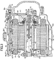
- Fig. 1 is a cross-sectional view for schematically explaining a configuration of an electric vehicle 10 to which the present invention is suitably applied.
- the electric vehicle 10 includes a drive device (vehicle drive device) 14 driving a pair of right and left drive wheels (wheels) not shown by an electric motor (rotating electric machine) 12 that is a drive power source for running.
- a drive device vehicle drive device
- a pair of right and left drive wheels wheels
- an electric motor rotating electric machine
- the drive device 14 includes an electric motor 12, a power transmission mechanism 16 transmitting a rotational drive power from the electric motor 12 to the pair of right and left drive wheels or transmitting a rotational drive power from the pair of right and left drive wheels to the electric motor 12, i.e., transmitting a rotational drive power between the electric motor 12 and the pair of right and left drive wheels, a housing (casing) 18 housing the electric motor 12, the power transmission mechanism 16 etc., and drive shafts 20L, 20R rotating together with the pair of right and left drive wheels.
- the power transmission mechanism 16 includes a gear mechanism 22 coupled to the electric motor 12 in a power transmittable manner and a differential device 24 coupled to the gear mechanism 22 in a power transmittable manner.
- the electric motor 12 includes, for example, a cylindrical stator 12a fixed to the housing 18 and a cylindrical rotor 12b fixed to a rotor shaft 26, such that the outer surface of the rotor 12b is apart from the inner surface of the cylindrical stator 12a by a predetermined gap.
- the cylindrical rotor shaft 26 penetrating through and integrally fixed to the cylindrical rotor 12b is rotatably supported around a first rotation axis C1 by the housing 18 via a pair of first bearings 28a, 28b, and the rotor 12b is rotatably supported around the first rotation axis C1 by the rotor shaft 26.
- the stator 12a includes a cylindrical stator core 12d having multiple magnetic steel plates 12c (see Fig. 3 ) laminated in a first rotation axis C1 direction and coil ends 12e wound around the stator core 12d on both sides of the stator core 12d in the direction of the first rotation axis C1.
- the differential device 24 includes a container-shaped differential casing 24a rotatably supported around a second rotation axis C2, a differential ring gear 24c fixed to an outer circumferential portion 24b of the differential casing 24a, a columnar pinion shaft 24e having both end portions supported by the differential casing 24a and fixed to the differential casing 24a by a knock pin 24d in a posture orthogonal to the second rotation axis C2, a pair of side gears 24f rotatably arranged around the second rotation axis C2 in a facing state across the pinion shaft 24e and housed in the differential casing 24a, and a pair of pinions 24g meshing with the pair of the side gears 24f and rotating together with the differential casing 24a while the pinion shaft 24e is inserted through the pair of pinions 24g such that the pair of pinions 24g are rotatably supported by the pinion shaft 24e.
- the pair of drive shafts 20L, 20R are respectively coupled to
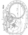
- the gear mechanism 22 includes a cylindrical first rotating shaft 22a coupled to the rotor shaft 26, which is disposed in the electric motor 12, in a power transmittable manner, a pinion 22b formed integrally with the first rotating shaft 22a, a small diameter gear 22c meshed with the differential ring gear 24c disposed in the differential device 24, a large diameter gear 22d having a diameter larger than the small diameter gear 22c and meshed with the pinion 22b formed on the first rotating shaft 22a, and a cylindrical second rotating shaft 22e to which the small diameter gear 22c and the large diameter gear 22d are integrally fixed.
- the second rotating shaft 22e is rotatably supported around a third rotation axis C3 by the housing 18 via a pair of second bearings 30a, 30b respectively disposed at both end portions of the second rotating shaft 22e.
- the first rotating shaft 22a is rotatably supported around the first rotation axis C1 by the housing 18 via a pair of third bearings 32a, 32b respectively disposed at both end portions of the first rotating shaft 22a, i.e., rotatably supported around the same rotation axis C1 as the rotor shaft 26 disposed in the electric motor 12.
- the housing 18 includes a first casing member 34, a second casing member 36 integrally fixed to the first casing member 34 by a first fastening bolt Bo1 (see Fig. 1 ), and a third casing member 38 integrally fixed to the first casing member 34 by a second fastening bolt Bo2 (see Figs. 1 and 3 ).
- the housing 18 is provided to have a first housing space S1 formed by the first casing member 34 and the second casing member 36, and a second housing space S2 formed by the first casing member 34 and the third casing member 38, and the first housing space S1 houses the power transmission mechanism 16 etc., i.e., the gear mechanism 22, the differential device 24, etc., and second housing space S2 houses the electric motor 12 etc.
- the first casing member 34 is provided with a partition wall 34a separating the first housing space S1 and the second housing space S2
- the second casing member 36 is provided with a wall portion 36a facing the partition wall 34a formed in the first casing member 34
- the third casing member 38 is provided with a wall portion 38a facing the partition wall 34a formed in the first casing member 34.
- the drive device 14 is provided with a lubricating path 42 including a mechanical oil pump 40 driven by running of the vehicle 10, i.e., by rotational drive of the second rotating shaft 22e of the gear mechanism 22, and the pump 40 pumps up an oil stored in the housing 18 and supplies the oil to the power transmission mechanism 16 etc. for lubricating the power transmission mechanism 16 etc., and a cooling path 46 that is separated from the lubricating path 42 and provided for the electric motor 12, the cooling path 46 including an electric oil pump 44 driven by an electronic control device 11 to pump up the oil stored in the housing 18 by the electric oil pump 44 to supply the oil exclusively to the electric motor 12 for cooling the electric motor 12.
- the mechanical oil pump 40 is an internal gear type oil pump and corresponds to a first oil pump of the present invention.
- the mechanical oil pump 40 includes a pump chamber S3 formed by the wall portion 36a of the second casing member 36 and a pump cover 48 attached to the wall portion 36a of the second casing member 36, an annular inner rotor 40a having multiple outer circumferential teeth and rotatably supported around the third rotation axis C3 by a pump drive shaft 50 coupled to the second rotating shaft 22e, and an annular outer rotor 40b having multiple inner circumferential teeth meshed with the outer circumferential teeth of the inner rotor 40a and rotatably supported around a rotation axis eccentric from the third rotation axis C3 by a recess portion 36b formed in the wall portion 36a of the second casing member 36.
- the inner rotor 40a and the outer rotor 40b are housed in the pump chamber S3.
- the mechanical oil pump 40 includes a suction-side connection port 48a formed in a sliding surface of the pump cover 48 for the inner rotor 40a and the outer rotor 40b and connected to a suction oil passage (not shown) for sucking the oil (see Fig. 4 ) stored in a first storage space S1a of the housing 18, a first pressure-feed-side connection port 48b formed in the sliding surface of the pump cover 48 for the inner rotor 40a and the outer rotor 40b, and a second pressure-feed-side connection port 36c formed in a sliding surface for the inner rotor 40a and the outer rotor 40b in the recess portion 36b formed in the wall portion 36a of the second casing member 36.
- the oil (see Fig. 4 ) stored in the first storage space S1a of the housing 18 is pumped up and taken into any one of multiple spaces, which are partitioned and formed by the inner circumferential teeth of the outer rotor 40b and the outer circumferential teeth of the inner rotor 40a, from the suction-side connection port 48a.
- the oil taken into the space is compressed by being carried to a circumferential position at which the volume of the space decreases as the inner rotor 40a rotates, and the oil having a pressure increased by the compression is discharged from the first pressure-feed-side connection port 48b and the second pressure-feed-side connection port 36c.
- a first oil level OL1 indicated by a dashed-dotted line is a line indicative of an oil level of the oil stored in the first storage space S1a of the housing 18 during running of the vehicle 10
- a second oil level OL2 indicated by a dashed-two dotted line is a line indicative of an oil level of the oil stored in the first storage space S1a of the housing 18 during stop of the vehicle 10.
- the lubricating path 42 is provided with a first supply oil passage 52 supplying a portion of the oil discharged from the mechanical oil pump 40 to the second bearing 30a, for example, and a second supply oil passage 54 supplying another portion of the oil discharged from the mechanical oil pump 40 to the gear mechanism 22, the second bearing 30b, and the third bearing 32a, for example.
- the first supply oil passage 52 includes an axial oil passage 50a formed in the pump drive shaft 50, an oil providing passage 48c formed in the pump cover 48 for supplying the oil discharged from the first pressure-feed-side connection port 48b to the axial oil passage 50a of the pump drive shaft 50, and an internal space S4 of the cylindrical second rotating shaft 22e communicating with the axial oil passage 50a of the pump drive shaft 50.
- the first supply oil passage 52 configured as described above supplies the oil discharged from the oil pump 40 to the second bearing 30a as indicated by arrows F1 shown in Figs. 1 and 2 .
- the arrows F1 are arrows indicative of a flow of the oil discharged by the mechanical oil pump 40 to the first pressure-feed-side connection port 48b.
- the pump cover 48 is provided with a relief valve 56 for discharging a portion of the oil discharged to the first pressure-feed-side connection port 48b by the mechanical oil pump 40, for example, if a discharge amount of the oil discharged to the oil providing passage 48c by the mechanical oil pump 40 becomes excessive or if the oil pressure becomes abnormally high due to clogging of an oil passage etc.
- the second supply oil passage 54 includes an oil providing passage 36d formed in the wall portion 36a of the second casing member 36 along the wall portion 36a and communicating with the second pressure-feed-side connection port 36c, a first branch oil passage 36e branched from the oil providing passage 36d and communicating with a space S5 around the second bearing 30b in the first housing space S1, a second branch oil passage 36f branched from the oil providing passage 36d and communicating with an internal space S6 of the cylindrical first rotating shaft 22a, and a third branch oil passage 36g branched from the oil providing passage 36d and communicating with an internal space S7 of a catch tank 58 storing a portion of the oil discharged from the mechanical oil pump 40.
- a first branch oil passage 36e branched from the oil providing passage 36d and communicating with a space S5 around the second bearing 30b in the first housing space S1
- a second branch oil passage 36f branched from the oil providing passage 36d and communicating with an internal space S6 of the cylindrical first rotating shaft 22a
- the second supply oil passage 54 includes the internal space S6 of the first rotating shaft 22a, a radial oil passage 22f formed in the first rotating shaft 22a, the internal space S7 of the catch tank 58, and a discharge port 58a formed in the catch tank 58.
- the catch tank 58 is disposed in the lubricating path 42, and the catch tank 58 is arranged, for example, on the vertically upper side of the mechanical oil pump 40 in the first housing space S1 of the housing 18.
- the first branch oil passage 36e, the second branch oil passage 36f, and the third branch oil passage 36g are provided with respective orifices 60, 62, 36h.
- the oil discharged from the mechanical oil pump 40 is supplied to the oil providing passage 36d as indicated by an arrow F2 shown in Figs. 1 and 2 .
- a portion of the oil supplied to the oil providing passage 36d is supplied through the first branch oil passage 36e to the second bearing 30b as indicated by an arrow F3 shown in Figs. 1 and 2 .
- a portion of the oil supplied to the oil providing passage 36d is supplied through the second branch oil passage 36f to the internal space S6 of the first rotating shaft 22a as indicated by an arrow F4 shown in Figs.
- the oil supplied to the internal space S6 of the first rotating shaft 22a is ejected to the third bearing 32a in accordance with a centrifugal force from the radial oil passage 22f formed in the first rotating shaft 22a.
- a portion of the oil supplied to the oil providing passage 36d passes through the third branch oil passage 36g and is stored in the catch tank 58 as indicated by an arrow F5 shown in Fig. 1 and Fig. 2 , and the oil stored in the catch tank 58 is ejected from the discharge port 58a formed in the catch tank 58 to the pinion 22b formed on the first rotating shaft 22a.
- the arrows F2 to F5 are arrows indicative of a flow of the oil discharged by the mechanical oil pump 40 to the second pressure-feed-side connection port 36c.
- the electric oil pump 44 corresponds to a second oil pump of the present invention and is driven by a drive command (drive current) supplied from an electronic control device 11, for example, and controlled to rotate at a target rotation speed calculated by the electronic control device 11.
- a drive command (drive current) supplied from an electronic control device 11, for example, and controlled to rotate at a target rotation speed calculated by the electronic control device 11.
- the electronic control device 11 based on a signal indicative of a temperature Ts (°C) of the stator core 12d of the electric motor 12 supplied from a temperature sensor 13 detecting the temperature Ts, when the temperature Ts becomes higher than a predefined temperature Ts1 (°C), the drive command (drive current) is output to the electric oil pump 44 and, for example, the electronic control device 11 performs the calculation such that the target rotation speed of the electric oil pump 44 becomes higher when the temperature Ts is higher.
- the cooling path 46 includes an oil cooler 64 (see Fig. 1 ) cooling the oil supplied to the electric motor 12, a cooling pipe 66 having at least one first discharge hole 66a and at least one second discharge hole 66b discharging the oil for cooling the electric motor 12, i.e., the oil cooled by the oil cooler 64, a suction oil passage 68 (see Fig.
- the housing 18 is provided with flowing holes allowing the oil stored in the second storage space S2a of the housing 18 and the oil stored in the first storage space S1a of the housing 18 described above (see Fig. 4 ) to respectively flow.
- the cooling pipe 66 is formed in a tubular shape, and an end portion 66f of the tubular cooling pipe 66 on the first housing space S1 side is fixed to the partition wall 34a of the first casing member 34, while an end portion 66g of the tubular cooling pipe 66 on the side opposite to the first housing space S1 is fixed to the wall portion 38a of the third casing member 38.
- the cooling pipe 66 is arranged vertically above the electric motor 12 in the second housing space S2 of the housing 18, and the end portion 66g of the cooling pipe 66 is provided with the oil introduction port 66e opened at an end of the cooling pipe 66.
- the supply oil passage 70 includes a first supply oil passage 38b formed in the wall portion 38a of the third casing member 38, and the wall portion 38a of the third casing member 38 is provided with a conduit, i.e., an orifice 38c, formed between the first supply oil passage 38b and the oil introduction port 66e of the cooling pipe 66 and having a flow-passage cross-sectional area smaller than the first supply oil passage 38b.
- the first supply oil passage 38b is a columnar space extended in an axial direction of the cooling pipe 66.
- the flow-passage cross-sectional area of the orifice 38c is, for example, an area of a cut section obtained by cutting the orifice 38c in the vertical direction (a cut section cut orthogonally to an oil flow direction), and the flow-passage cross-sectional area of the first supply oil passage 38b is, for example, an area of a cut section obtained by cutting the first supply oil passage 38b in the vertical direction (a cut section cut orthogonally to the oil flow direction).
- the wall portion 38a of the third casing member 38 is integrally provided with a cylindrical projecting portion 38d projecting in a cylindrical shape from the wall portion 38a into the internal space S8 of the rotor shaft 26 and a shaft-shaped shaft member 74 screwed into a female thread portion 38e formed on an internal circumferential surface of the cylindrical projecting portion 38d.
- a cylindrical projecting portion 38d projecting in a cylindrical shape from the wall portion 38a into the internal space S8 of the rotor shaft 26 and a shaft-shaped shaft member 74 screwed into a female thread portion 38e formed on an internal circumferential surface of the cylindrical projecting portion 38d.
- the branch oil passage 72 includes a first branch oil passage 38f formed to branch from the first supply oil passage 38b in the wall portion 38a of the third casing member 38 and extending in a columnar shape along the wall portion 38a, an axial oil passage 74a formed in the shaft member 74 and extending in an axial direction of the shaft member 74, i.e., in the first rotation axis C1 direction, a radial oil passage 74b communicating with the axial oil passage 74a and formed in a radial direction of the shaft member 74, and a communication oil passage 38g allowing communication between the axial oil passage 74a and the first branch oil passage 38f.
- the communication oil passage 38g is a space formed in the wall portion 38a of the third casing member 38 by a cover member 76 fixedly disposed on the wall portion 38a of the third casing member 38.
- the branch oil passage 72 configured as described above guides into the internal space S8 of the rotor shaft 26 a portion of the oil supplied to the supply oil passage 70.
- Arrows F7 shown in Figs. 1 and 3 are an arrow indicative of a flow of the oil supplied to the branch oil passage 72.
- the rotor 12b of the electric motor 12 is provided with a pair of disk-shaped first and second plates 12f, 12g adjacent to both ends of the rotor 12b in the first rotation axis C1 direction, and the first plate 12f is provided with a first ejection hole 12h that communicates with a first radial oil passage (radial oil passage) 26a formed in the rotor shaft 26 and that ejects the oil supplied from the first radial oil passage 26a in accordance with a centrifugal force toward the coil end 12e of the stator 12a disposed in the electric motor 12, while the second plate 12g is provided with a second ejection hole 12i that communicates with a second radial oil passage (radial oil passage) 26b formed in the rotor shaft 26 and that ejects the oil supplied from the second radial oil passage 26b in accordance with a centrifugal force toward the coil end 12e.
- the first radial oil passage 26a and the second radial oil passage 26b formed in the rotor shaft 26 function as ejection holes ejecting the oil supplied to the internal space S8 of the rotor shaft 26 in accordance with the centrifugal force toward the coil ends 12e by using the first ejection hole 12h formed in the first plate 12f and the second ejection hole 12i formed in the second plate 12g.
- the first radial oil passage 26a and the second radial oil passage 26b formed in the rotor shaft 26 communicate with the internal space S8 of the rotor shaft 26.
- the oil stored in the first storage space S1a in the housing 18 is pumped up by the mechanical oil pump 40, and the pumped-up oil is supplied through the first supply oil passage 52 and the second supply oil passage 54 to the power transmission mechanism 16, for example, the second bearings 30a, 30b, the third bearing 32a, and the pinion 22b of the first rotating shaft 22a, to lubricate the power transmission mechanism 16.
- the power transmission mechanism 16 is lubricated with the lubricating path 42, and the electric oil pump 44 is driven to pump up the oil stored in the second storage space S2a of the housing 18, and the pumped-up oil is supplied to the electric motor 12 to cool the electric motor 12.
- the drive device 14 of this example is provided with the lubricating path 42 including the mechanical oil pump 40 to pump up the oil stored in the housing 18 by the mechanical oil pump 40 and to supply the oil to the power transmission mechanism 16 for lubricating the power transmission mechanism 16 and the cooling path 46 that is separated from the lubricating path 42 and provided for the electric motor 12, the cooling path including the electric oil pump 44 to pump up the oil stored in the housing 18 by the electric oil pump 44 to supply the oil exclusively to the electric motor 12 for cooling the electric motor 12, and the cooling path 46 is provided with the oil cooler 64 cooling the oil to be supplied to the electric motor 12.
- the drive device 14 has the cooling path 46 provided for the electric motor 12 for cooling the electric motor 12 and the lubricating path 42 for lubricating the power transmission mechanism 16 disposed as separate paths, and therefore, only when the electric motor 12 needs to be cooled, the electric oil pump 44 can be driven so that only the electric motor 12 can sufficiently be cooled with the cooling path 46 provided for the electric motor 12. Additionally, the mechanical oil pump 40 does not need to cool the electric motor 12 due to the provision of the cooling path 46 and can therefore suitably be reduced in size as compared to a conventional oil pump lubricating the power transmission mechanism 16 while cooling the electric motor 12, for example.
- the cooling path 46 is provided with the oil cooler 64 cooling the oil supplied to the electric motor 12, a flow rate of the oil discharged from the electric oil pump 44 for cooling the electric motor 12 can be prevented from increasing, and the electric oil pump 44 can suitably be reduced in size. This makes it possible to sufficiently ensure a cooling performance for cooling the electric motor 12 and to reduce a power loss due to lubrication of the power transmission mechanism 16 and cooling of the electric motor 12 during running.
- the electric oil pump 44 is driven when the temperature Ts of the stator core 12d is higher than the predefined temperature Ts1. Therefore, the electric oil pump 44 can be driven only when the temperature Ts of the stator core 12d is higher than the predefined temperature Ts1 so that the electric motor 12 needs to be cooled.
- the lubricating path 42 is provided with the catch tank 58 storing a portion of the oil discharged from the mechanical oil pump 40 and ejecting the stored oil to the power transmission mechanism 16. Therefore, since a portion of the oil discharged from the mechanical oil pump 40 is stored in the catch tank 58, the oil level OL1 of the oil stored in the first storage space S1a of the housing 18 has a suitably lowered height, which suitably reduces an agitation loss when the differential ring gear 24c disposed in the differential device 24 of the power transmission mechanism 16 agitates the oil stored in the first storage space S1a of the housing 18.
- the cooling path 46 is provided with the cooling pipe 66 into which a portion of the oil discharged from the electric oil pump 44 is introduced and that discharges the introduced oil to the electric motor 12. Therefore, the oil stored in the second storage space S2a of the housing 18 is pumped up by the electric oil pump 44, and the pumped-up oil is discharged from the cooling pipe 66 to the electric motor 12, so that the electric motor 12 is suitably cooled with the oil.
- the rotor 12b disposed in the electric motor 12 is rotatably supported by the cylindrical rotor shaft 26 penetrating through and integrally fixed to the rotor 12b such that a portion of the oil discharged from the electric oil pump 44 is introduced into the internal space S8, and the cooling path 46 is provided with the first radial oil passage 26a and the second radial oil passage 26b formed in the rotor shaft 26 to eject the oil introduced into the internal space S8 of the rotor shaft 26 to the electric motor 12.
- the oil stored in the second storage space S2a of the housing 18 is pumped up by the electric oil pump 44, and the oil introduced into the internal space S8 of the rotor shaft 26 is ejected due to a centrifugal force from the first radial oil passage 26a and the second radial oil passage 26b formed in the rotor shaft 26 to the electric motor 12, so that the electric motor 12 is suitably cooled with the oil.
- the rotor 12b disposed in the electric motor 12 is rotatably supported by the cylindrical rotor shaft 26 penetrating through and integrally fixed to the rotor 12b such that a portion of oil discharged from the electric oil pump 44 is introduced into the internal space S8, and the cooling path 46 is provided with the supply oil passage 70 for supplying the oil discharged from the electric oil pump 44 to the oil introduction port 66e of the cooling pipe 66, the branch oil passage 72 branched from the supply oil passage 70 and guiding to the internal space S8 of the rotor shaft 26 a portion of the oil supplied to the supply oil passage 70, and the first radial oil passage 26a and the second radial oil passage 26b formed in the rotor shaft 26 to eject the oil introduced into the internal space S8 of the rotor shaft 26 to the electric motor 12.
- a portion of the oil supplied to the supply oil passage 70 is introduced into the internal space S8 of the rotor shaft 26 through the branch oil passage 72, and the oil introduced into the internal space S8 of the rotor shaft 26 is ejected due to a centrifugal force to the electric motor 12 from the first radial oil passage 26a and the second radial oil passage 26b disposed in the rotor shaft 26, while another portion of the oil supplied to the supply oil passage 70 is discharged from the cooling pipe 66 to the electric motor 12, so that the electric motor 12 is suitably cooled with the oil.
- the orifice 38c made smaller in flow-passage cross-sectional area than the first supply oil passage 38b of the supply oil passage 70 is formed between the first supply oil passage 38b and the oil introduction port 66e of the cooling pipe 66. Therefore, the oil supplied through the orifice 38c to the supply oil passage 70 is prevented from being excessively supplied to the cooling pipe 66, so that the oil introduced into the internal space S8 of the rotor shaft 26 is suitably prevented from becoming insufficient in flow rate.
- the drive device 14 is applied to the electric vehicle 10 using the electric motor 12 as the drive power source in the first example, the drive device 14 may be applied to a hybrid vehicle using an electric motor and an engine as drive power sources, for example.
- the mechanical oil pump 40 is an internal gear type oil pump in the drive device 14 of the example
- the mechanical oil pump 40 may be an external gear type oil pump or a vane type oil pump, for example, and an oil pump of any type may be used as long as the oil pump is driven by running of a vehicle so that an oil is discharged from the oil pump.
- the electric oil pump 44 is driven when the temperature Ts of the stator core 12d is higher than the predefined temperature Ts1; however, for example, the electric oil pump 44 may be driven when the temperature of the coil ends 12e of the electric motor 12 is higher than a predetermined temperature.
- a portion of the oil discharged from the mechanical oil pump 40 is stored in the catch tank 58; however, for example, all the oil discharged from the mechanical oil pump 40 may be stored in the catch tank 58.
- the oil stored in the catch tank 58 is ejected to the pinion 22b formed on the first rotating shaft 22a disposed in the power transmission mechanism 16, the oil stored in the catch tank 58 may be ejected to a component constituting the power transmission mechanism 16 other than the first rotating shaft 22a.
- a portion of the oil discharged from the electric oil pump 44 is introduced into the cooling pipe 66 via the first supply oil passage 38b formed in the third casing member 38; however, for example, the first branch oil passage 38f may not be formed in the third casing member 38, and all the oil discharged from the electric oil pump 44 may be introduced into the cooling pipe 66.
- a portion of the oil discharged from the electric oil pump 44 is introduced into the internal space S8 of the rotor shaft 26 via the first branch oil passage 38f formed in the third casing member 38; however, for example, the cooling pipe 66 may not be disposed in the cooling path 46, and all the oil discharged from the electric oil pump 44 may be introduced into the internal space S8 of the rotor shaft 26.
Landscapes
- Engineering & Computer Science (AREA)
- General Engineering & Computer Science (AREA)
- Mechanical Engineering (AREA)
- Chemical & Material Sciences (AREA)
- Combustion & Propulsion (AREA)
- Transportation (AREA)
- Power Engineering (AREA)
- Motor Or Generator Cooling System (AREA)
- Motor Or Generator Frames (AREA)
- General Details Of Gearings (AREA)
Abstract
A vehicle drive device is provided with a lubricating path including a first oil pump to pump up an oil stored in the casing by the first oil pump and to supply the oil to the power transmission mechanism for lubricating the power transmission mechanism, and a cooling path that is separated from the lubricating circuit and provided for the rotating electric machine, the cooling path including a second oil pump to pump up the oil stored in the casing by the second oil pump to supply the oil exclusively to the rotating electric machine for cooling the rotating electric machine, the second oil pump is an electric oil pump, and the cooling path is provided with an oil cooler cooling the oil to be supplied to the rotating electric machine.
Description
- The present invention relates to a technique in a vehicle drive device supplying an oil stored in a casing housing a rotating electric machine and a power transmission mechanism to the power transmission mechanism and the rotating electric machine to lubricate the power transmission mechanism and to cool the rotating electric machine, for sufficiently ensuring a cooling performance for cooling the rotating electric machine while a power loss due to lubrication of the power transmission mechanism and cooling of the rotating electric machine during running of a vehicle is reduced.
- There is known a vehicle drive device that includes (a) a rotating electric machine, (b) a power transmission mechanism transmitting a rotational drive power between the rotating electric machine and multiple wheels, and (c) a casing housing the rotating electric machine and the power transmission mechanism and (d) that supplies an oil stored in the casing to the power transmission mechanism and the rotating electric machine to lubricate the power transmission mechanism and to cool the rotating electric machine. For example, this corresponds to a vehicle drive device described in Patent Document 1. In Patent Document 1, the oil stored in the casing is pumped up by a mechanical oil pump, and the pumped-up oil is supplied to the power transmission mechanism and the rotating electric machine.
- Patent Document 1: Japanese Laid-Open Patent Publication No.
2013-119918 - In the vehicle drive device as described in Patent Document 1, the oil pumped up by the mechanical oil pump is used for lubrication of the power transmission mechanism and cooling of the rotating electric machine through one path, and therefore, for example, a portion of the oil pumped up by the mechanical oil pump for lubricating the power transmission mechanism is consumed in the cooling of the rotating electric machine, so that a cooling performance for cooling the rotating electric machine deteriorates. Therefore, to sufficiently ensure the cooling performance for cooling the rotating electric machine, i.e., to increase a flow rate of the oil supplied to the rotating electric machine, the mechanical oil pump must be increased in size, causing a problem of an increased power loss due to driving of the oil pump. Additionally, when the temperature of the oil rises, it is required to further increase the flow rate of the oil supplied to the rotating electric machine for cooling the rotating electric machine.
- The present invention was conceived in view of the situations and it is therefore an object of the present invention to provide a vehicle drive device which sufficiently ensures a cooling performance for cooling a rotating electric machine and reduces a power loss due to lubrication of a power transmission mechanism and cooling of the rotating electric machine during running.
- To achieve the above object, a first aspect of the present invention provides a vehicle drive device comprising: (a) a rotating electric machine; a power transmission mechanism transmitting a rotational drive power between the rotating electric machine and multiple wheels; and a casing housing the rotating electric machine and the power transmission mechanism, the vehicle drive device supplying an oil stored in the casing to the power transmission mechanism and the rotating electric machine to lubricate the power transmission mechanism and to cool the rotating electric machine, wherein the vehicle drive device is provided with (b) a lubricating path including a first oil pump to pump up an oil stored in the casing by the first oil pump and to supply the oil to the power transmission mechanism for lubricating the power transmission mechanism, and (c) a cooling path that is separated from the lubricating path and provided for the rotating electric machine, the cooling path including a second oil pump to pump up the oil stored in the casing by the second oil pump to supply the oil exclusively to the rotating electric machine for cooling the rotating electric machine, wherein (d) the second oil pump is an electric oil pump, and wherein (e) the cooling path is provided with an oil cooler cooling the oil to be supplied to the rotating electric machine.
- The vehicle drive device according to the first aspect of the invention is provided with the lubricating path including the first oil pump to pump up the oil stored in the casing by the first oil pump and to supply the oil to the power transmission mechanism for lubricating the power transmission mechanism and the cooling path that is separated from the lubricating path and provided for the rotating electric machine, the cooling path including the second oil pump to pump up the oil stored in the casing by the second oil pump to supply the oil exclusively to the rotating electric machine for cooling the rotating electric machine, the second oil pump is an electric oil pump, and the cooling path is provided with the oil cooler cooling the oil to be supplied to the rotating electric machine. Therefore, the vehicle drive device has the cooling path provided for the rotating electric machine for cooling the rotating electric machine and the lubricating path for lubricating the power transmission mechanism disposed as separate paths, and therefore, only when the rotating electric machine needs to be cooled, the electric oil pump i.e. the second oil pump can be driven so that only the rotating electric machine can sufficiently be cooled by the cooling path provided for the rotating electric machine. Additionally, the first oil pump does not need to cool the rotating electric machine due to the provision of the cooling path and can therefore suitably be reduced in size as compared to a conventional oil pump lubricating the power transmission mechanism while cooling the rotating electric machine, for example. Furthermore, since the cooling path is provided with the oil cooler cooling the oil supplied to the rotating electric machine, a flow rate of the oil discharged from the second oil pump for cooling the rotating electric machine can be prevented from increasing, and the second oil pump can suitably be reduced in size. This makes it possible to sufficiently ensure a cooling performance for cooling the rotating electric machine and to reduce a power loss due to lubrication of the power transmission mechanism and cooling of the rotating electric machine during running.
-
-
Fig. 1 is a cross-sectional view for schematically explaining a configuration of a drive device of an electric vehicle to which the present invention is suitably applied. -
Fig. 2 is an enlarged view ofFig. 1 showing details of a lubricating path provided in the drive device ofFig. 1 . -
Fig. 3 is an enlarged view ofFig. 1 showing details of a cooling path disposed in the drive device ofFig. 1 . -
Fig. 4 is a cross-sectional view of a catch tank disposed in the lubricating path ofFig. 2 . - A second aspect of the present invention provides the vehicle drive device recited in the first aspect of the invention, wherein the second oil pump is driven when a temperature of a stator of the rotating electrical machine is higher than a predetermined temperature. Therefore, the electric oil pump i.e. the second oil pump can be driven only when the temperature of the stator is higher than the predetermined temperature so that the rotating electric machine needs to be cooled.
- A third aspect of the present invention provides the vehicle drive device recited in the first or second aspect of the invention, wherein the lubricating path is provided with a catch tank storing at least a portion of the oil discharged from the first oil pump and ejecting the stored oil to the power transmission mechanism. Therefore, since at least a portion of the oil discharged from the first oil pump is stored in the catch tank, a level of the oil stored in the casing has a suitably lowered height, which suitably reduces an agitation loss when the gear disposed in the power transmission mechanism agitates the oil stored in the casing.
- A fourth aspect of the present invention provides the vehicle drive device recited in any one of the first to third aspects of the invention, wherein the cooling path is provided with a cooling pipe into which at least a portion of the oil discharged from the second oil pump is introduced and which discharges the introduced oil to the rotating electric machine. Therefore, the oil stored in the casing is pumped up by the second oil pump, and the pumped-up oil is discharged from the cooling pipe to the rotating electric machine, so that the rotating electric machine is suitably cooled with the oil.
- A fifth aspect of the present invention provides the vehicle drive device recited in any one of the first to fourth aspects of the invention, wherein (a) a rotor disposed in the rotating electric machine is rotatably supported by a cylindrical rotor shaft penetrating through and integrally fixed to the rotor such that at least a portion of the oil discharged from the second oil pump is introduced into the inside of the rotor shaft, and wherein (b) the cooling path includes a radial oil passage formed in the rotor shaft to eject the oil introduced into the inside of the rotor shaft to the rotating electric machine. Therefore, the oil stored in the casing is pumped up by the second oil pump, and the oil introduced into the rotor shaft is ejected due to a centrifugal force from the radial oil passage formed in the rotor shaft to the rotating electric machine, so that the rotating electric machine is suitably cooled with the oil.
- A sixth aspect of the present invention provides the vehicle drive device recited in the fourth aspect of the invention, wherein (a) a rotor disposed in the rotating electric machine is rotatably supported by a cylindrical rotor shaft penetrating through and integrally fixed to the rotor such that at least a portion of the oil discharged from the second oil pump is introduced into the inside of the rotor shaft, and wherein (b) the cooling path includes a supply oil passage for supplying the oil discharged from the second oil pump to an oil introduction port of the cooling pipe, a branch oil passage branched from the supply oil passage to introduce a portion of the oil supplied to the supply oil passage to the inside of the rotor shaft, and a radial oil passage formed in the rotor shaft to eject the oil introduced into the inside of the rotor shaft to the rotating electric machine. Therefore, a portion of the oil supplied to the supply oil passage is introduced into the rotor shaft through the branch oil passage, and the portion of the oil is ejected due to a centrifugal force to the rotating electric machine from the radial oil passage formed in the rotor shaft, while another portion of the oil supplied to the oil supplied to the supply oil passage is discharged from the cooling pipe to the rotating electric machine, so that the rotating electric machine is suitably cooled with the oil.
- A seventh aspect of the present invention provides the vehicle drive device recited in the sixth aspect of the invention, wherein an orifice is provided between the supply oil passage and the oil introduction port of the cooling pipe such that a cross-sectional area in flow-passage is smaller than in the supply oil passage. Therefore, the oil supplied through the orifice to the supply oil passage is prevented from being excessively supplied to the cooling pipe, so that the oil introduced into the rotor shaft is suitably prevented from becoming insufficient in flow rate.
- An example of the present invention will be described in detail with reference to the drawings. In the following example, the figures are simplified or deformed as appropriate and portions are not necessarily precisely drawn in terms of dimension ratio, shape, etc.
-
Fig. 1 is a cross-sectional view for schematically explaining a configuration of anelectric vehicle 10 to which the present invention is suitably applied. Theelectric vehicle 10 includes a drive device (vehicle drive device) 14 driving a pair of right and left drive wheels (wheels) not shown by an electric motor (rotating electric machine) 12 that is a drive power source for running. As shown inFig. 1 , thedrive device 14 includes anelectric motor 12, apower transmission mechanism 16 transmitting a rotational drive power from theelectric motor 12 to the pair of right and left drive wheels or transmitting a rotational drive power from the pair of right and left drive wheels to theelectric motor 12, i.e., transmitting a rotational drive power between theelectric motor 12 and the pair of right and left drive wheels, a housing (casing) 18 housing theelectric motor 12, thepower transmission mechanism 16 etc., and driveshafts 20L, 20R rotating together with the pair of right and left drive wheels. Thepower transmission mechanism 16 includes agear mechanism 22 coupled to theelectric motor 12 in a power transmittable manner and adifferential device 24 coupled to thegear mechanism 22 in a power transmittable manner. - As shown in
Fig. 1 , theelectric motor 12 includes, for example, acylindrical stator 12a fixed to thehousing 18 and acylindrical rotor 12b fixed to arotor shaft 26, such that the outer surface of therotor 12b is apart from the inner surface of thecylindrical stator 12a by a predetermined gap. Thecylindrical rotor shaft 26 penetrating through and integrally fixed to thecylindrical rotor 12b is rotatably supported around a first rotation axis C1 by thehousing 18 via a pair offirst bearings rotor 12b is rotatably supported around the first rotation axis C1 by therotor shaft 26. Thestator 12a includes acylindrical stator core 12d having multiple magnetic steel plates 12c (seeFig. 3 ) laminated in a first rotation axis C1 direction andcoil ends 12e wound around thestator core 12d on both sides of thestator core 12d in the direction of the first rotation axis C1. - As shown in
Fig. 1 , thedifferential device 24 includes a container-shapeddifferential casing 24a rotatably supported around a second rotation axis C2, adifferential ring gear 24c fixed to an outercircumferential portion 24b of thedifferential casing 24a, acolumnar pinion shaft 24e having both end portions supported by thedifferential casing 24a and fixed to thedifferential casing 24a by a knock pin 24d in a posture orthogonal to the second rotation axis C2, a pair ofside gears 24f rotatably arranged around the second rotation axis C2 in a facing state across thepinion shaft 24e and housed in thedifferential casing 24a, and a pair ofpinions 24g meshing with the pair of theside gears 24f and rotating together with thedifferential casing 24a while thepinion shaft 24e is inserted through the pair ofpinions 24g such that the pair ofpinions 24g are rotatably supported by thepinion shaft 24e. The pair ofdrive shafts 20L, 20R are respectively coupled to the pair of theside gears 24f. - As shown in
Figs. 1 and2 , thegear mechanism 22 includes a cylindrical first rotatingshaft 22a coupled to therotor shaft 26, which is disposed in theelectric motor 12, in a power transmittable manner, apinion 22b formed integrally with the first rotatingshaft 22a, asmall diameter gear 22c meshed with thedifferential ring gear 24c disposed in thedifferential device 24, alarge diameter gear 22d having a diameter larger than thesmall diameter gear 22c and meshed with thepinion 22b formed on the first rotatingshaft 22a, and a cylindrical second rotatingshaft 22e to which thesmall diameter gear 22c and thelarge diameter gear 22d are integrally fixed. In thegear mechanism 22, the second rotatingshaft 22e is rotatably supported around a third rotation axis C3 by thehousing 18 via a pair ofsecond bearings shaft 22e. The first rotatingshaft 22a is rotatably supported around the first rotation axis C1 by thehousing 18 via a pair ofthird bearings shaft 22a, i.e., rotatably supported around the same rotation axis C1 as therotor shaft 26 disposed in theelectric motor 12. - As shown in
Figs. 1 to 3 , thehousing 18 includes afirst casing member 34, asecond casing member 36 integrally fixed to thefirst casing member 34 by a first fastening bolt Bo1 (seeFig. 1 ), and athird casing member 38 integrally fixed to thefirst casing member 34 by a second fastening bolt Bo2 (seeFigs. 1 and3 ). Thehousing 18 is provided to have a first housing space S1 formed by thefirst casing member 34 and thesecond casing member 36, and a second housing space S2 formed by thefirst casing member 34 and thethird casing member 38, and the first housing space S1 houses thepower transmission mechanism 16 etc., i.e., thegear mechanism 22, thedifferential device 24, etc., and second housing space S2 houses theelectric motor 12 etc. Thefirst casing member 34 is provided with apartition wall 34a separating the first housing space S1 and the second housing space S2, thesecond casing member 36 is provided with awall portion 36a facing thepartition wall 34a formed in thefirst casing member 34, and thethird casing member 38 is provided with awall portion 38a facing thepartition wall 34a formed in thefirst casing member 34. - As shown in
Figs. 1 to 3 , thedrive device 14 is provided with alubricating path 42 including amechanical oil pump 40 driven by running of thevehicle 10, i.e., by rotational drive of the second rotatingshaft 22e of thegear mechanism 22, and thepump 40 pumps up an oil stored in thehousing 18 and supplies the oil to thepower transmission mechanism 16 etc. for lubricating thepower transmission mechanism 16 etc., and acooling path 46 that is separated from thelubricating path 42 and provided for theelectric motor 12, thecooling path 46 including anelectric oil pump 44 driven by anelectronic control device 11 to pump up the oil stored in thehousing 18 by theelectric oil pump 44 to supply the oil exclusively to theelectric motor 12 for cooling theelectric motor 12. - The
mechanical oil pump 40 is an internal gear type oil pump and corresponds to a first oil pump of the present invention. As shown inFig. 2 , themechanical oil pump 40 includes a pump chamber S3 formed by thewall portion 36a of thesecond casing member 36 and apump cover 48 attached to thewall portion 36a of thesecond casing member 36, an annularinner rotor 40a having multiple outer circumferential teeth and rotatably supported around the third rotation axis C3 by apump drive shaft 50 coupled to the second rotatingshaft 22e, and an annularouter rotor 40b having multiple inner circumferential teeth meshed with the outer circumferential teeth of theinner rotor 40a and rotatably supported around a rotation axis eccentric from the third rotation axis C3 by arecess portion 36b formed in thewall portion 36a of thesecond casing member 36. Theinner rotor 40a and theouter rotor 40b are housed in the pump chamber S3. - The
mechanical oil pump 40 includes a suction-side connection port 48a formed in a sliding surface of thepump cover 48 for theinner rotor 40a and theouter rotor 40b and connected to a suction oil passage (not shown) for sucking the oil (seeFig. 4 ) stored in a first storage space S1a of thehousing 18, a first pressure-feed-side connection port 48b formed in the sliding surface of thepump cover 48 for theinner rotor 40a and theouter rotor 40b, and a second pressure-feed-side connection port 36c formed in a sliding surface for theinner rotor 40a and theouter rotor 40b in therecess portion 36b formed in thewall portion 36a of thesecond casing member 36. When theinner rotor 40a and theouter rotor 40b are rotationally driven in themechanical oil pump 40, the oil (seeFig. 4 ) stored in the first storage space S1a of thehousing 18 is pumped up and taken into any one of multiple spaces, which are partitioned and formed by the inner circumferential teeth of theouter rotor 40b and the outer circumferential teeth of theinner rotor 40a, from the suction-side connection port 48a. The oil taken into the space is compressed by being carried to a circumferential position at which the volume of the space decreases as theinner rotor 40a rotates, and the oil having a pressure increased by the compression is discharged from the first pressure-feed-side connection port 48b and the second pressure-feed-side connection port 36c. InFig. 4 , a first oil level OL1 indicated by a dashed-dotted line is a line indicative of an oil level of the oil stored in the first storage space S1a of thehousing 18 during running of thevehicle 10, and a second oil level OL2 indicated by a dashed-two dotted line is a line indicative of an oil level of the oil stored in the first storage space S1a of thehousing 18 during stop of thevehicle 10. - As shown in
Figs. 1 and2 , the lubricatingpath 42 is provided with a firstsupply oil passage 52 supplying a portion of the oil discharged from themechanical oil pump 40 to thesecond bearing 30a, for example, and a secondsupply oil passage 54 supplying another portion of the oil discharged from themechanical oil pump 40 to thegear mechanism 22, thesecond bearing 30b, and thethird bearing 32a, for example. - As shown in
Fig. 2 , the firstsupply oil passage 52 includes anaxial oil passage 50a formed in thepump drive shaft 50, anoil providing passage 48c formed in thepump cover 48 for supplying the oil discharged from the first pressure-feed-side connection port 48b to theaxial oil passage 50a of thepump drive shaft 50, and an internal space S4 of the cylindrical secondrotating shaft 22e communicating with theaxial oil passage 50a of thepump drive shaft 50. When the oil is discharged from themechanical oil pump 40 to the first pressure-feed-side connection port 48b, the firstsupply oil passage 52 configured as described above supplies the oil discharged from theoil pump 40 to thesecond bearing 30a as indicated by arrows F1 shown inFigs. 1 and2 . The arrows F1 are arrows indicative of a flow of the oil discharged by themechanical oil pump 40 to the first pressure-feed-side connection port 48b. Thepump cover 48 is provided with arelief valve 56 for discharging a portion of the oil discharged to the first pressure-feed-side connection port 48b by themechanical oil pump 40, for example, if a discharge amount of the oil discharged to theoil providing passage 48c by themechanical oil pump 40 becomes excessive or if the oil pressure becomes abnormally high due to clogging of an oil passage etc. - As shown in
Fig. 2 , the secondsupply oil passage 54 includes anoil providing passage 36d formed in thewall portion 36a of thesecond casing member 36 along thewall portion 36a and communicating with the second pressure-feed-side connection port 36c, a firstbranch oil passage 36e branched from theoil providing passage 36d and communicating with a space S5 around thesecond bearing 30b in the first housing space S1, a secondbranch oil passage 36f branched from theoil providing passage 36d and communicating with an internal space S6 of the cylindrical firstrotating shaft 22a, and a thirdbranch oil passage 36g branched from theoil providing passage 36d and communicating with an internal space S7 of acatch tank 58 storing a portion of the oil discharged from themechanical oil pump 40. As shown inFig. 2 , the secondsupply oil passage 54 includes the internal space S6 of the firstrotating shaft 22a, aradial oil passage 22f formed in the firstrotating shaft 22a, the internal space S7 of thecatch tank 58, and adischarge port 58a formed in thecatch tank 58. Thecatch tank 58 is disposed in the lubricatingpath 42, and thecatch tank 58 is arranged, for example, on the vertically upper side of themechanical oil pump 40 in the first housing space S1 of thehousing 18. The firstbranch oil passage 36e, the secondbranch oil passage 36f, and the thirdbranch oil passage 36g are provided withrespective orifices - In the second
supply oil passage 54 configured as described above, when the oil is discharged by themechanical oil pump 40 to the second pressure-feed-side connection port 36c, the oil discharged from themechanical oil pump 40 is supplied to theoil providing passage 36d as indicated by an arrow F2 shown inFigs. 1 and2 . For example, a portion of the oil supplied to theoil providing passage 36d is supplied through the firstbranch oil passage 36e to thesecond bearing 30b as indicated by an arrow F3 shown inFigs. 1 and2 . For example, a portion of the oil supplied to theoil providing passage 36d is supplied through the secondbranch oil passage 36f to the internal space S6 of the firstrotating shaft 22a as indicated by an arrow F4 shown inFigs. 1 and2 , and the oil supplied to the internal space S6 of the firstrotating shaft 22a is ejected to thethird bearing 32a in accordance with a centrifugal force from theradial oil passage 22f formed in the firstrotating shaft 22a. For example, a portion of the oil supplied to theoil providing passage 36d passes through the thirdbranch oil passage 36g and is stored in thecatch tank 58 as indicated by an arrow F5 shown inFig. 1 andFig. 2 , and the oil stored in thecatch tank 58 is ejected from thedischarge port 58a formed in thecatch tank 58 to thepinion 22b formed on the firstrotating shaft 22a. The arrows F2 to F5 are arrows indicative of a flow of the oil discharged by themechanical oil pump 40 to the second pressure-feed-side connection port 36c. - The
electric oil pump 44 corresponds to a second oil pump of the present invention and is driven by a drive command (drive current) supplied from anelectronic control device 11, for example, and controlled to rotate at a target rotation speed calculated by theelectronic control device 11. In theelectronic control device 11, based on a signal indicative of a temperature Ts (°C) of thestator core 12d of theelectric motor 12 supplied from atemperature sensor 13 detecting the temperature Ts, when the temperature Ts becomes higher than a predefined temperature Ts1 (°C), the drive command (drive current) is output to theelectric oil pump 44 and, for example, theelectronic control device 11 performs the calculation such that the target rotation speed of theelectric oil pump 44 becomes higher when the temperature Ts is higher. - As shown in
Figs. 1 and3 , the coolingpath 46 includes an oil cooler 64 (seeFig. 1 ) cooling the oil supplied to theelectric motor 12, a coolingpipe 66 having at least onefirst discharge hole 66a and at least one second discharge hole 66b discharging the oil for cooling theelectric motor 12, i.e., the oil cooled by theoil cooler 64, a suction oil passage 68 (seeFig. 1 ) for sucking an oil stored in a second storage space S2a of thehousing 18, i.e., for pumping up an oil stored in the second storage space S2a, asupply oil passage 70 for supplying the oil discharged from theelectric oil pump 44 through theoil cooler 64 to anoil introduction port 66e of the coolingpipe 66, and abranch oil passage 72 branched from thesupply oil passage 70 and guiding to an internal space (inside) S8 of therotor shaft 26 a portion of the oil supplied to thesupply oil passage 70. Although not shown, thehousing 18 is provided with flowing holes allowing the oil stored in the second storage space S2a of thehousing 18 and the oil stored in the first storage space S1a of thehousing 18 described above (seeFig. 4 ) to respectively flow. - As shown in
Figs. 1 and3 , the coolingpipe 66 is formed in a tubular shape, and anend portion 66f of thetubular cooling pipe 66 on the first housing space S1 side is fixed to thepartition wall 34a of thefirst casing member 34, while anend portion 66g of thetubular cooling pipe 66 on the side opposite to the first housing space S1 is fixed to thewall portion 38a of thethird casing member 38. The coolingpipe 66 is arranged vertically above theelectric motor 12 in the second housing space S2 of thehousing 18, and theend portion 66g of the coolingpipe 66 is provided with theoil introduction port 66e opened at an end of the coolingpipe 66. In the coolingpipe 66 configured as described above, when the oil is introduced from thesupply oil passage 70 to theoil introduction port 66e, the introduced oil is discharged from the at least onefirst discharge hole 66a and the at least one second discharge hole 66b formed in the coolingpipe 66 to thestator core 12d and the coil ends 12e disposed in theelectric motor 12. Arrows F6 shown inFigs. 1 and3 are arrows indicative of a flow of the oil introduced into theoil introduction port 66e of the coolingpipe 66. - As shown in
Figs. 1 and3 , thesupply oil passage 70 includes a firstsupply oil passage 38b formed in thewall portion 38a of thethird casing member 38, and thewall portion 38a of thethird casing member 38 is provided with a conduit, i.e., anorifice 38c, formed between the firstsupply oil passage 38b and theoil introduction port 66e of the coolingpipe 66 and having a flow-passage cross-sectional area smaller than the firstsupply oil passage 38b. The firstsupply oil passage 38b is a columnar space extended in an axial direction of the coolingpipe 66. The flow-passage cross-sectional area of theorifice 38c is, for example, an area of a cut section obtained by cutting theorifice 38c in the vertical direction (a cut section cut orthogonally to an oil flow direction), and the flow-passage cross-sectional area of the firstsupply oil passage 38b is, for example, an area of a cut section obtained by cutting the firstsupply oil passage 38b in the vertical direction (a cut section cut orthogonally to the oil flow direction). - As shown in
Fig. 3 , thewall portion 38a of thethird casing member 38 is integrally provided with a cylindrical projectingportion 38d projecting in a cylindrical shape from thewall portion 38a into the internal space S8 of therotor shaft 26 and a shaft-shapedshaft member 74 screwed into afemale thread portion 38e formed on an internal circumferential surface of the cylindrical projectingportion 38d. As shown inFig. 3 , thebranch oil passage 72 includes a firstbranch oil passage 38f formed to branch from the firstsupply oil passage 38b in thewall portion 38a of thethird casing member 38 and extending in a columnar shape along thewall portion 38a, anaxial oil passage 74a formed in theshaft member 74 and extending in an axial direction of theshaft member 74, i.e., in the first rotation axis C1 direction, aradial oil passage 74b communicating with theaxial oil passage 74a and formed in a radial direction of theshaft member 74, and acommunication oil passage 38g allowing communication between theaxial oil passage 74a and the firstbranch oil passage 38f. Thecommunication oil passage 38g is a space formed in thewall portion 38a of thethird casing member 38 by acover member 76 fixedly disposed on thewall portion 38a of thethird casing member 38. When the oil discharged from theelectric oil pump 44 is supplied to thesupply oil passage 70, thebranch oil passage 72 configured as described above guides into the internal space S8 of therotor shaft 26 a portion of the oil supplied to thesupply oil passage 70. Arrows F7 shown inFigs. 1 and3 are an arrow indicative of a flow of the oil supplied to thebranch oil passage 72. - As shown in
Fig. 3 , therotor 12b of theelectric motor 12 is provided with a pair of disk-shaped first andsecond plates rotor 12b in the first rotation axis C1 direction, and thefirst plate 12f is provided with afirst ejection hole 12h that communicates with a first radial oil passage (radial oil passage) 26a formed in therotor shaft 26 and that ejects the oil supplied from the firstradial oil passage 26a in accordance with a centrifugal force toward thecoil end 12e of thestator 12a disposed in theelectric motor 12, while thesecond plate 12g is provided with asecond ejection hole 12i that communicates with a second radial oil passage (radial oil passage) 26b formed in therotor shaft 26 and that ejects the oil supplied from the secondradial oil passage 26b in accordance with a centrifugal force toward thecoil end 12e. Therefore, the firstradial oil passage 26a and the secondradial oil passage 26b formed in therotor shaft 26 function as ejection holes ejecting the oil supplied to the internal space S8 of therotor shaft 26 in accordance with the centrifugal force toward the coil ends 12e by using thefirst ejection hole 12h formed in thefirst plate 12f and thesecond ejection hole 12i formed in thesecond plate 12g. The firstradial oil passage 26a and the secondradial oil passage 26b formed in therotor shaft 26 communicate with the internal space S8 of therotor shaft 26. - In the
drive device 14 configured as described above, if the temperature Ts of thestator core 12d is lower than the predefined temperature Ts1 during running of thevehicle 10 and it is not necessary to cool theelectric motor 12, the oil stored in the first storage space S1a in thehousing 18 is pumped up by themechanical oil pump 40, and the pumped-up oil is supplied through the firstsupply oil passage 52 and the secondsupply oil passage 54 to thepower transmission mechanism 16, for example, thesecond bearings third bearing 32a, and thepinion 22b of the firstrotating shaft 22a, to lubricate thepower transmission mechanism 16. If the temperature Ts of thestator core 12d is higher than the predefined temperature Ts1 during running of thevehicle 10 so that theelectric motor 12 needs to be cooled, thepower transmission mechanism 16 is lubricated with the lubricatingpath 42, and theelectric oil pump 44 is driven to pump up the oil stored in the second storage space S2a of thehousing 18, and the pumped-up oil is supplied to theelectric motor 12 to cool theelectric motor 12. - As described above, the
drive device 14 of this example is provided with the lubricatingpath 42 including themechanical oil pump 40 to pump up the oil stored in thehousing 18 by themechanical oil pump 40 and to supply the oil to thepower transmission mechanism 16 for lubricating thepower transmission mechanism 16 and the coolingpath 46 that is separated from the lubricatingpath 42 and provided for theelectric motor 12, the cooling path including theelectric oil pump 44 to pump up the oil stored in thehousing 18 by theelectric oil pump 44 to supply the oil exclusively to theelectric motor 12 for cooling theelectric motor 12, and the coolingpath 46 is provided with theoil cooler 64 cooling the oil to be supplied to theelectric motor 12. Therefore, thedrive device 14 has the coolingpath 46 provided for theelectric motor 12 for cooling theelectric motor 12 and the lubricatingpath 42 for lubricating thepower transmission mechanism 16 disposed as separate paths, and therefore, only when theelectric motor 12 needs to be cooled, theelectric oil pump 44 can be driven so that only theelectric motor 12 can sufficiently be cooled with the coolingpath 46 provided for theelectric motor 12. Additionally, themechanical oil pump 40 does not need to cool theelectric motor 12 due to the provision of the coolingpath 46 and can therefore suitably be reduced in size as compared to a conventional oil pump lubricating thepower transmission mechanism 16 while cooling theelectric motor 12, for example. Furthermore, since the coolingpath 46 is provided with theoil cooler 64 cooling the oil supplied to theelectric motor 12, a flow rate of the oil discharged from theelectric oil pump 44 for cooling theelectric motor 12 can be prevented from increasing, and theelectric oil pump 44 can suitably be reduced in size. This makes it possible to sufficiently ensure a cooling performance for cooling theelectric motor 12 and to reduce a power loss due to lubrication of thepower transmission mechanism 16 and cooling of theelectric motor 12 during running. - According to the
drive device 14 of this example, theelectric oil pump 44 is driven when the temperature Ts of thestator core 12d is higher than the predefined temperature Ts1. Therefore, theelectric oil pump 44 can be driven only when the temperature Ts of thestator core 12d is higher than the predefined temperature Ts1 so that theelectric motor 12 needs to be cooled. - According to the
drive device 14 of this example, the lubricatingpath 42 is provided with thecatch tank 58 storing a portion of the oil discharged from themechanical oil pump 40 and ejecting the stored oil to thepower transmission mechanism 16. Therefore, since a portion of the oil discharged from themechanical oil pump 40 is stored in thecatch tank 58, the oil level OL1 of the oil stored in the first storage space S1a of thehousing 18 has a suitably lowered height, which suitably reduces an agitation loss when thedifferential ring gear 24c disposed in thedifferential device 24 of thepower transmission mechanism 16 agitates the oil stored in the first storage space S1a of thehousing 18. - According to the
drive device 14 of this example, the coolingpath 46 is provided with the coolingpipe 66 into which a portion of the oil discharged from theelectric oil pump 44 is introduced and that discharges the introduced oil to theelectric motor 12. Therefore, the oil stored in the second storage space S2a of thehousing 18 is pumped up by theelectric oil pump 44, and the pumped-up oil is discharged from the coolingpipe 66 to theelectric motor 12, so that theelectric motor 12 is suitably cooled with the oil. - According to the
drive device 14 of this example, therotor 12b disposed in theelectric motor 12 is rotatably supported by thecylindrical rotor shaft 26 penetrating through and integrally fixed to therotor 12b such that a portion of the oil discharged from theelectric oil pump 44 is introduced into the internal space S8, and the coolingpath 46 is provided with the firstradial oil passage 26a and the secondradial oil passage 26b formed in therotor shaft 26 to eject the oil introduced into the internal space S8 of therotor shaft 26 to theelectric motor 12. Therefore, the oil stored in the second storage space S2a of thehousing 18 is pumped up by theelectric oil pump 44, and the oil introduced into the internal space S8 of therotor shaft 26 is ejected due to a centrifugal force from the firstradial oil passage 26a and the secondradial oil passage 26b formed in therotor shaft 26 to theelectric motor 12, so that theelectric motor 12 is suitably cooled with the oil. - According to the
drive device 14 of this example, therotor 12b disposed in theelectric motor 12 is rotatably supported by thecylindrical rotor shaft 26 penetrating through and integrally fixed to therotor 12b such that a portion of oil discharged from theelectric oil pump 44 is introduced into the internal space S8, and the coolingpath 46 is provided with thesupply oil passage 70 for supplying the oil discharged from theelectric oil pump 44 to theoil introduction port 66e of the coolingpipe 66, thebranch oil passage 72 branched from thesupply oil passage 70 and guiding to the internal space S8 of therotor shaft 26 a portion of the oil supplied to thesupply oil passage 70, and the firstradial oil passage 26a and the secondradial oil passage 26b formed in therotor shaft 26 to eject the oil introduced into the internal space S8 of therotor shaft 26 to theelectric motor 12. Therefore, a portion of the oil supplied to thesupply oil passage 70 is introduced into the internal space S8 of therotor shaft 26 through thebranch oil passage 72, and the oil introduced into the internal space S8 of therotor shaft 26 is ejected due to a centrifugal force to theelectric motor 12 from the firstradial oil passage 26a and the secondradial oil passage 26b disposed in therotor shaft 26, while another portion of the oil supplied to thesupply oil passage 70 is discharged from the coolingpipe 66 to theelectric motor 12, so that theelectric motor 12 is suitably cooled with the oil. - According to the
drive device 14 of this example, theorifice 38c made smaller in flow-passage cross-sectional area than the firstsupply oil passage 38b of thesupply oil passage 70 is formed between the firstsupply oil passage 38b and theoil introduction port 66e of the coolingpipe 66. Therefore, the oil supplied through theorifice 38c to thesupply oil passage 70 is prevented from being excessively supplied to the coolingpipe 66, so that the oil introduced into the internal space S8 of therotor shaft 26 is suitably prevented from becoming insufficient in flow rate. - Although the example of the present invention has been described with reference to the drawings, the present invention is also applied in other forms.
- For example, although the
drive device 14 is applied to theelectric vehicle 10 using theelectric motor 12 as the drive power source in the first example, thedrive device 14 may be applied to a hybrid vehicle using an electric motor and an engine as drive power sources, for example. - Although the
mechanical oil pump 40 is an internal gear type oil pump in thedrive device 14 of the example, themechanical oil pump 40 may be an external gear type oil pump or a vane type oil pump, for example, and an oil pump of any type may be used as long as the oil pump is driven by running of a vehicle so that an oil is discharged from the oil pump. - In the
drive device 14 of the example, theelectric oil pump 44 is driven when the temperature Ts of thestator core 12d is higher than the predefined temperature Ts1; however, for example, theelectric oil pump 44 may be driven when the temperature of the coil ends 12e of theelectric motor 12 is higher than a predetermined temperature. - In the
drive device 14 of the example, a portion of the oil discharged from themechanical oil pump 40 is stored in thecatch tank 58; however, for example, all the oil discharged from themechanical oil pump 40 may be stored in thecatch tank 58. Although the oil stored in thecatch tank 58 is ejected to thepinion 22b formed on the firstrotating shaft 22a disposed in thepower transmission mechanism 16, the oil stored in thecatch tank 58 may be ejected to a component constituting thepower transmission mechanism 16 other than the firstrotating shaft 22a. - In the
drive device 14 of the example, a portion of the oil discharged from theelectric oil pump 44 is introduced into the coolingpipe 66 via the firstsupply oil passage 38b formed in thethird casing member 38; however, for example, the firstbranch oil passage 38f may not be formed in thethird casing member 38, and all the oil discharged from theelectric oil pump 44 may be introduced into the coolingpipe 66. In thedrive device 14 of the example, a portion of the oil discharged from theelectric oil pump 44 is introduced into the internal space S8 of therotor shaft 26 via the firstbranch oil passage 38f formed in thethird casing member 38; however, for example, the coolingpipe 66 may not be disposed in thecooling path 46, and all the oil discharged from theelectric oil pump 44 may be introduced into the internal space S8 of therotor shaft 26. - The above description is merely an embodiment, and the present invention can be implemented in variously modified and improved forms based on the knowledge of those skilled in the art.
-
- 12: electric motor (rotating electric machine)
- 12b: rotor
- 14: drive device (vehicle drive device)
- 16: power transmission mechanism
- 18: housing (casing)
- 26: rotor shaft
- 26a: first radial oil passage (radial oil passage)
- 26b: second radial oil passage (radial oil passage)
- 38c: orifice
- 40: mechanical oil pump (first oil pump)
- 42: lubricating path
- 44: electric oil pump (second oil pump)
- 46: cooling path
- 58: catch tank
- 64: oil cooler
- 66: cooling pipe
- 66e: oil introduction port
- 70: supply oil passage
- 72: branch oil passage
- Ts: temperature of a stator of the electric motor
- Ts1: predefined temperature
- S8: internal space
Claims (7)
- A vehicle drive device (14) comprising: a rotating electric machine (12); a power transmission mechanism (16) transmitting a rotational drive power between the rotating electric machine and multiple wheels; and a casing (18) housing the rotating electric machine and the power transmission mechanism, the vehicle drive device supplying an oil stored in the casing to the power transmission mechanism and the rotating electric machine to lubricate the power transmission mechanism and to cool the rotating electric machine, wherein
the vehicle drive device is provided with
a lubricating path (42) including a first oil pump (40) to pump up an oil stored in the casing by the first oil pump and to supply the oil to the power transmission mechanism for lubricating the power transmission mechanism, and
a cooling path (46) that is separated from the lubricating path and provided for the rotating electric machine, the cooling path including a second oil pump (44) to pump up the oil stored in the casing by the second oil pump to supply the oil exclusively to the rotating electric machine for cooling the rotating electric machine, wherein
the second oil pump is an electric oil pump, and wherein
the cooling path is provided with an oil cooler (64) cooling the oil to be supplied to the rotating electric machine. - The vehicle drive device according to claim 1, wherein the second oil pump is driven when a temperature (Ts) of a stator (12a) of the rotating electric machine is higher than a predetermined temperature (Ts1).
- The vehicle drive device according to claim 1 or 2, wherein
the lubricating path is provided with a catch tank (58) storing at least a portion of the oil discharged from the first oil pump and ejecting the stored oil to the power transmission mechanism. - The vehicle drive device according to any one of claims 1 to 3, wherein the cooling path is provided with a cooling pipe (66) into which at least a portion of the oil discharged from the second oil pump is introduced and which discharges the introduced oil to the rotating electric machine.
- The vehicle drive device according to any one of claims 1 to 4, wherein
a rotor (12b) disposed in the rotating electric machine is rotatably supported by a cylindrical rotor shaft (26) penetrating through and integrally fixed to the rotor such that at least a portion of the oil discharged from the second oil pump is introduced into the inside (S8) of the rotor shaft, and wherein
the cooling path includes a radial oil passage (26a, 26b) formed in the rotor shaft to eject the oil introduced into the inside of the rotor shaft to the rotating electric machine. - The vehicle drive device according to according to claim 4, wherein
a rotor (12b) disposed in the rotating electric machine is rotatably supported by a cylindrical rotor shaft (26) penetrating through and integrally fixed to the rotor such that at least a portion of the oil discharged from the second oil pump is introduced into the inside (S8) of the rotor shaft, and wherein
the cooling path includes a supply oil passage (70) for supplying the oil discharged from the second oil pump to an oil introduction port (66e) of the cooling pipe, a branch oil passage (72) branched from the supply oil passage to introduce a portion of the oil supplied to the supply oil passage to the inside of the rotor shaft, and a radial oil passage (26a, 26b) formed in the rotor shaft to eject the oil introduced into the inside of the rotor shaft to the rotating electric machine. - The vehicle drive device according to claim 6, wherein an orifice (38c) is provided between the supply oil passage and the oil introduction port of the cooling pipe such that a cross-sectional area in flow-passage is smaller than in the supply oil passage.
Applications Claiming Priority (1)
| Application Number | Priority Date | Filing Date | Title |
|---|---|---|---|
| JP2018010021A JP2019129608A (en) | 2018-01-24 | 2018-01-24 | Vehicle drive |
Publications (1)
| Publication Number | Publication Date |
|---|---|
| EP3517745A1 true EP3517745A1 (en) | 2019-07-31 |
Family
ID=65234451
Family Applications (1)
| Application Number | Title | Priority Date | Filing Date |
|---|---|---|---|
| EP19153617.6A Withdrawn EP3517745A1 (en) | 2018-01-24 | 2019-01-24 | Vehicle drive device |
Country Status (6)
| Country | Link |
|---|---|
| US (1) | US11114921B2 (en) |
| EP (1) | EP3517745A1 (en) |
| JP (1) | JP2019129608A (en) |
| KR (1) | KR20190090347A (en) |
| CN (1) | CN110067848A (en) |
| BR (1) | BR102019001182A2 (en) |
Cited By (2)
| Publication number | Priority date | Publication date | Assignee | Title |
|---|---|---|---|---|
| EP3905490A4 (en) * | 2019-03-29 | 2022-02-09 | Aisin Corporation | Vehicle drive device |
| EP4108490A1 (en) * | 2021-06-22 | 2022-12-28 | Huawei Digital Power Technologies Co., Ltd. | Powertrain and electric vehicle |
Families Citing this family (39)
| Publication number | Priority date | Publication date | Assignee | Title |
|---|---|---|---|---|
| FR3048746B1 (en) * | 2016-03-10 | 2019-04-26 | Renault S.A.S | DEVICE FOR LUBRICATING A HOLLOW SHAFT AND GEARBOX COMPRISING A FIXED POWER CANNULA |
| JP6639328B2 (en) * | 2016-05-25 | 2020-02-05 | トヨタ自動車株式会社 | Power transmission device lubrication structure |
| JP6432571B2 (en) * | 2016-08-12 | 2018-12-05 | トヨタ自動車株式会社 | Hybrid vehicle lubrication system |
| JP7172762B2 (en) * | 2019-03-13 | 2022-11-16 | トヨタ自動車株式会社 | Control device for vehicle oil supply device |
| US10965183B2 (en) * | 2019-06-14 | 2021-03-30 | Honeywell International Inc. | Integrated traction drive system |
| CN114503399B (en) | 2019-09-30 | 2024-06-04 | 日本电产株式会社 | Motor unit |
| CN114423631B (en) * | 2019-11-14 | 2024-09-03 | 株式会社爱信 | Vehicle drive device |
| JP2021118628A (en) * | 2020-01-27 | 2021-08-10 | トヨタ自動車株式会社 | Cooling device of vehicle rotary electric machine |
| JP7392593B2 (en) * | 2020-07-01 | 2023-12-06 | マツダ株式会社 | vehicle |
| DE102020120419A1 (en) | 2020-08-03 | 2022-02-03 | Schaeffler Technologies AG & Co. KG | Oil supply device for a transmission section and transmission section with the oil supply device |
| DE102020121163A1 (en) | 2020-08-12 | 2022-02-17 | Schaeffler Technologies AG & Co. KG | System and method for temperature control in a power train |
| CN114087347A (en) * | 2020-08-25 | 2022-02-25 | 陕西汉德车桥有限公司 | Electric power assembly forced lubrication system |
| WO2022065411A1 (en) | 2020-09-25 | 2022-03-31 | 株式会社アイシン | Vehicle drive device |
| JP7477639B2 (en) * | 2020-11-06 | 2024-05-01 | ジヤトコ株式会社 | Apparatus and Plates |
| JP2022081338A (en) * | 2020-11-19 | 2022-05-31 | 日本電産株式会社 | Driving device |
| DE102021200278B4 (en) | 2021-01-14 | 2022-10-27 | Zf Friedrichshafen Ag | Driving device with a device for cooling and lubricating components of a vehicle |
| DE102021200276B4 (en) | 2021-01-14 | 2022-10-27 | Zf Friedrichshafen Ag | Driving device with a device for cooling and lubricating components of a vehicle |
| JP2022136854A (en) | 2021-03-08 | 2022-09-21 | 日本電産株式会社 | Drive device |
| JP2022136861A (en) | 2021-03-08 | 2022-09-21 | 日本電産株式会社 | Transmission mechanism device and drive device |
| JP2022136837A (en) | 2021-03-08 | 2022-09-21 | 日本電産株式会社 | Stator, rotary electric machine, drive unit, and mobile object |
| JP2022136504A (en) | 2021-03-08 | 2022-09-21 | 日本電産株式会社 | Drive device |
| DE102021106066A1 (en) | 2021-03-12 | 2022-09-15 | Schaeffler Technologies AG & Co. KG | Electrically operable drive train |
| DE102021202837A1 (en) | 2021-03-23 | 2022-09-29 | Volkswagen Aktiengesellschaft | Drive arrangement for a motor vehicle |
| JP2022149665A (en) | 2021-03-25 | 2022-10-07 | 日本電産株式会社 | Driving device |
| DE102022202609A1 (en) | 2021-03-26 | 2022-09-29 | Nidec Corporation | drive device |
| EP4261435A4 (en) | 2021-03-31 | 2024-08-14 | Aisin Corp | Drive device for vehicle |
| EP4362292A1 (en) * | 2021-06-21 | 2024-05-01 | Yamaha Hatsudoki Kabushiki Kaisha | Motor, motor unit, vehicle-driving motor unit, and electric vehicle |
| DE102021207713B3 (en) * | 2021-07-20 | 2022-09-22 | Zf Friedrichshafen Ag | drive unit |
| CN117716615A (en) | 2021-07-26 | 2024-03-15 | 株式会社爱信 | Driving device |
| CN117651817A (en) | 2021-07-30 | 2024-03-05 | Gkn汽车有限公司 | Electric drive for a vehicle |
| JP2024529986A (en) | 2021-07-30 | 2024-08-14 | ジーケーエヌ オートモーティブ リミテッド | Electric drive for a vehicle |
| US20240271694A1 (en) | 2021-07-30 | 2024-08-15 | Gkn Automotive Limited | Electric drive for a vehicle |
| WO2023006216A1 (en) | 2021-07-30 | 2023-02-02 | Gkn Automotive Limited | Electric drive arrangement for a vehicle |
| JP2023031031A (en) * | 2021-08-24 | 2023-03-08 | 日本電産株式会社 | Driving device |
| JP2023067110A (en) * | 2021-10-29 | 2023-05-16 | ニデック株式会社 | Drive device |
| JPWO2023112801A1 (en) | 2021-12-15 | 2023-06-22 | ||
| DE102022109970A1 (en) * | 2022-04-26 | 2023-10-26 | Audi Aktiengesellschaft | Geared motor for a motor vehicle and motor vehicle with a geared motor |
| FR3135500B1 (en) * | 2022-05-12 | 2024-05-24 | Renault Sas | Hybrid Powertrain Speed Reducer |
| JP2024103236A (en) * | 2023-01-20 | 2024-08-01 | トヨタ自動車株式会社 | Power transmission device and power unit equipped with same |
Citations (5)
| Publication number | Priority date | Publication date | Assignee | Title |
|---|---|---|---|---|
| DE4236124A1 (en) * | 1991-10-24 | 1993-05-13 | Aisin Aw Co | Battery-powered road vehicle - has oil circulation pump with separate electric drive supplying drive transmission upon failure of electric drive motor |
| JP2009096326A (en) * | 2007-10-17 | 2009-05-07 | Toyota Motor Corp | Driving control device for oil pump unit and hybrid car equipped with the driving control device |
| JP2013119918A (en) | 2011-12-08 | 2013-06-17 | Aisin Seiki Co Ltd | Power transmission device |
| DE102016122948A1 (en) * | 2015-12-09 | 2017-06-14 | Toyota Jidosha Kabushiki Kaisha | Power transmission system for a vehicle |
| JP2018057243A (en) * | 2016-09-30 | 2018-04-05 | アイシン・エィ・ダブリュ株式会社 | Vehicle drive device |
Family Cites Families (16)
| Publication number | Priority date | Publication date | Assignee | Title |
|---|---|---|---|---|
| JP2518464B2 (en) * | 1990-11-20 | 1996-07-24 | ヤマハ株式会社 | Music synthesizer |
| JP3211315B2 (en) * | 1991-12-25 | 2001-09-25 | アイシン・エィ・ダブリュ株式会社 | Cooling control device for motor for vehicle |
| JP3235208B2 (en) * | 1992-09-14 | 2001-12-04 | アイシン・エィ・ダブリュ株式会社 | Electric vehicle |
| JP5546311B2 (en) * | 2010-03-29 | 2014-07-09 | アイシン・エィ・ダブリュ株式会社 | Vehicle drive device |
| JP2011240772A (en) * | 2010-05-17 | 2011-12-01 | Ntn Corp | In-wheel motor drive device |
| JP5365880B2 (en) * | 2010-06-08 | 2013-12-11 | アイシン・エィ・ダブリュ株式会社 | Vehicle drive device |
| JP5382030B2 (en) * | 2011-02-23 | 2014-01-08 | アイシン・エィ・ダブリュ株式会社 | Friction plate lubrication device for automatic transmission |
| CN103688085B (en) | 2011-07-19 | 2015-04-08 | 丰田自动车株式会社 | Lubrication device of power transmission device for hybrid vehicle |
| US10778068B2 (en) | 2015-10-28 | 2020-09-15 | Mitsubishi Electric Corporation | Rotating electrical machine cooling structure, and control method thereof |
| US10442285B2 (en) * | 2015-11-24 | 2019-10-15 | Toyota Jidosha Kabushiki Kaisha | Cooling apparatus for vehicle |
| JP6652041B2 (en) * | 2015-12-21 | 2020-02-19 | トヨタ自動車株式会社 | Vehicle cooling system |
| EP3184336B1 (en) | 2015-12-21 | 2021-05-12 | Toyota Jidosha Kabushiki Kaisha | Vehicle with a vehicular cooling system |
| US10309524B2 (en) | 2016-02-03 | 2019-06-04 | Toyota Jidosha Kabushiki Kaisha | Lubricating device of power transmission device for vehicle |
| JP6477628B2 (en) | 2016-02-03 | 2019-03-06 | トヨタ自動車株式会社 | Lubricating device for vehicle power transmission device |
| JP2017136964A (en) | 2016-02-03 | 2017-08-10 | トヨタ自動車株式会社 | Lubrication device for hybrid vehicle |
| JP6664506B2 (en) | 2016-09-30 | 2020-03-13 | アイシン・エィ・ダブリュ株式会社 | Vehicle drive system |
-
2018
- 2018-01-24 JP JP2018010021A patent/JP2019129608A/en active Pending
-
2019
- 2019-01-22 CN CN201910059189.4A patent/CN110067848A/en active Pending
- 2019-01-22 KR KR1020190008148A patent/KR20190090347A/en active Search and Examination
- 2019-01-22 BR BR102019001182-3A patent/BR102019001182A2/en not_active IP Right Cessation
- 2019-01-24 US US16/256,643 patent/US11114921B2/en active Active
- 2019-01-24 EP EP19153617.6A patent/EP3517745A1/en not_active Withdrawn
Patent Citations (5)
| Publication number | Priority date | Publication date | Assignee | Title |
|---|---|---|---|---|
| DE4236124A1 (en) * | 1991-10-24 | 1993-05-13 | Aisin Aw Co | Battery-powered road vehicle - has oil circulation pump with separate electric drive supplying drive transmission upon failure of electric drive motor |
| JP2009096326A (en) * | 2007-10-17 | 2009-05-07 | Toyota Motor Corp | Driving control device for oil pump unit and hybrid car equipped with the driving control device |
| JP2013119918A (en) | 2011-12-08 | 2013-06-17 | Aisin Seiki Co Ltd | Power transmission device |
| DE102016122948A1 (en) * | 2015-12-09 | 2017-06-14 | Toyota Jidosha Kabushiki Kaisha | Power transmission system for a vehicle |
| JP2018057243A (en) * | 2016-09-30 | 2018-04-05 | アイシン・エィ・ダブリュ株式会社 | Vehicle drive device |
Cited By (4)
| Publication number | Priority date | Publication date | Assignee | Title |
|---|---|---|---|---|
| EP3905490A4 (en) * | 2019-03-29 | 2022-02-09 | Aisin Corporation | Vehicle drive device |
| US11608884B2 (en) | 2019-03-29 | 2023-03-21 | Aisin Corporation | Vehicle drive device |
| EP4108490A1 (en) * | 2021-06-22 | 2022-12-28 | Huawei Digital Power Technologies Co., Ltd. | Powertrain and electric vehicle |
| US12057763B2 (en) | 2021-06-22 | 2024-08-06 | Huawei Digital Power Technologies Co., Ltd. | Powertrain and electric vehicle |
Also Published As
| Publication number | Publication date |
|---|---|
| CN110067848A (en) | 2019-07-30 |
| KR20190090347A (en) | 2019-08-01 |
| US11114921B2 (en) | 2021-09-07 |
| JP2019129608A (en) | 2019-08-01 |
| US20190229582A1 (en) | 2019-07-25 |
| BR102019001182A2 (en) | 2019-08-06 |
Similar Documents
| Publication | Publication Date | Title |
|---|---|---|
| EP3517745A1 (en) | Vehicle drive device | |
| EP3534042B1 (en) | Vehicle drive device | |
| CN109790914B (en) | Vehicle drive device | |
| US8801397B2 (en) | Compressor | |
| US8678784B2 (en) | Drive device | |
| US20180223850A1 (en) | Compressor | |
| US10018266B2 (en) | Transmission | |
| JP2020148150A (en) | Control device of oil supply device for vehicle | |
| US11041387B2 (en) | Scroll fluid machine having injection holes through which lubricant is injected to the orbiting bearing | |
| CN112088262A (en) | Motor unit and vehicle drive device | |
| CN112533783B (en) | Motor unit | |
| CN115733299A (en) | Drive device | |
| EP3521622A1 (en) | Gear pump or gear motor | |
| JP2014025427A (en) | Compressor | |
| EP3741996B1 (en) | Rotary screw compressor | |
| JPWO2018030325A1 (en) | Drive unit | |
| JP2010048146A (en) | Inverter integrated type motor-driven compressor | |
| CN112041592B (en) | Motor unit | |
| CN112840538A (en) | Rotating electric machine and motor unit | |
| JP7480755B2 (en) | Vehicle drive device | |
| JP7452423B2 (en) | motor | |
| CN212392766U (en) | Drive device | |
| EP3447295A1 (en) | Open-type compressor | |
| CN117774678A (en) | Electric vehicle drive system with cooling system | |
| JP2022068430A (en) | Transaxle |
Legal Events
| Date | Code | Title | Description |
|---|---|---|---|
| PUAI | Public reference made under article 153(3) epc to a published international application that has entered the european phase |
Free format text: ORIGINAL CODE: 0009012 |
|
| STAA | Information on the status of an ep patent application or granted ep patent |
Free format text: STATUS: REQUEST FOR EXAMINATION WAS MADE |
|
| 17P | Request for examination filed |
Effective date: 20190225 |
|
| AK | Designated contracting states |
Kind code of ref document: A1 Designated state(s): AL AT BE BG CH CY CZ DE DK EE ES FI FR GB GR HR HU IE IS IT LI LT LU LV MC MK MT NL NO PL PT RO RS SE SI SK SM TR |
|
| AX | Request for extension of the european patent |
Extension state: BA ME |
|
| STAA | Information on the status of an ep patent application or granted ep patent |
Free format text: STATUS: THE APPLICATION HAS BEEN WITHDRAWN |
|
| 18W | Application withdrawn |
Effective date: 20211221 |