EP3517339B1 - State-of-charge display system - Google Patents
State-of-charge display system Download PDFInfo
- Publication number
- EP3517339B1 EP3517339B1 EP19152339.8A EP19152339A EP3517339B1 EP 3517339 B1 EP3517339 B1 EP 3517339B1 EP 19152339 A EP19152339 A EP 19152339A EP 3517339 B1 EP3517339 B1 EP 3517339B1
- Authority
- EP
- European Patent Office
- Prior art keywords
- soc
- battery
- lighting elements
- motor vehicle
- light array
- Prior art date
- Legal status (The legal status is an assumption and is not a legal conclusion. Google has not performed a legal analysis and makes no representation as to the accuracy of the status listed.)
- Active
Links
Images



Classifications
-
- B—PERFORMING OPERATIONS; TRANSPORTING
- B60—VEHICLES IN GENERAL
- B60L—PROPULSION OF ELECTRICALLY-PROPELLED VEHICLES; SUPPLYING ELECTRIC POWER FOR AUXILIARY EQUIPMENT OF ELECTRICALLY-PROPELLED VEHICLES; ELECTRODYNAMIC BRAKE SYSTEMS FOR VEHICLES IN GENERAL; MAGNETIC SUSPENSION OR LEVITATION FOR VEHICLES; MONITORING OPERATING VARIABLES OF ELECTRICALLY-PROPELLED VEHICLES; ELECTRIC SAFETY DEVICES FOR ELECTRICALLY-PROPELLED VEHICLES
- B60L3/00—Electric devices on electrically-propelled vehicles for safety purposes; Monitoring operating variables, e.g. speed, deceleration or energy consumption
- B60L3/12—Recording operating variables ; Monitoring of operating variables
-
- B—PERFORMING OPERATIONS; TRANSPORTING
- B60—VEHICLES IN GENERAL
- B60Q—ARRANGEMENT OF SIGNALLING OR LIGHTING DEVICES, THE MOUNTING OR SUPPORTING THEREOF OR CIRCUITS THEREFOR, FOR VEHICLES IN GENERAL
- B60Q1/00—Arrangement of optical signalling or lighting devices, the mounting or supporting thereof or circuits therefor
- B60Q1/26—Arrangement of optical signalling or lighting devices, the mounting or supporting thereof or circuits therefor the devices being primarily intended to indicate the vehicle, or parts thereof, or to give signals, to other traffic
- B60Q1/44—Arrangement of optical signalling or lighting devices, the mounting or supporting thereof or circuits therefor the devices being primarily intended to indicate the vehicle, or parts thereof, or to give signals, to other traffic for indicating braking action or preparation for braking, e.g. by detection of the foot approaching the brake pedal
-
- B—PERFORMING OPERATIONS; TRANSPORTING
- B60—VEHICLES IN GENERAL
- B60K—ARRANGEMENT OR MOUNTING OF PROPULSION UNITS OR OF TRANSMISSIONS IN VEHICLES; ARRANGEMENT OR MOUNTING OF PLURAL DIVERSE PRIME-MOVERS IN VEHICLES; AUXILIARY DRIVES FOR VEHICLES; INSTRUMENTATION OR DASHBOARDS FOR VEHICLES; ARRANGEMENTS IN CONNECTION WITH COOLING, AIR INTAKE, GAS EXHAUST OR FUEL SUPPLY OF PROPULSION UNITS IN VEHICLES
- B60K35/00—Instruments specially adapted for vehicles; Arrangement of instruments in or on vehicles
- B60K35/10—Input arrangements, i.e. from user to vehicle, associated with vehicle functions or specially adapted therefor
-
- B—PERFORMING OPERATIONS; TRANSPORTING
- B60—VEHICLES IN GENERAL
- B60K—ARRANGEMENT OR MOUNTING OF PROPULSION UNITS OR OF TRANSMISSIONS IN VEHICLES; ARRANGEMENT OR MOUNTING OF PLURAL DIVERSE PRIME-MOVERS IN VEHICLES; AUXILIARY DRIVES FOR VEHICLES; INSTRUMENTATION OR DASHBOARDS FOR VEHICLES; ARRANGEMENTS IN CONNECTION WITH COOLING, AIR INTAKE, GAS EXHAUST OR FUEL SUPPLY OF PROPULSION UNITS IN VEHICLES
- B60K35/00—Instruments specially adapted for vehicles; Arrangement of instruments in or on vehicles
- B60K35/20—Output arrangements, i.e. from vehicle to user, associated with vehicle functions or specially adapted therefor
- B60K35/21—Output arrangements, i.e. from vehicle to user, associated with vehicle functions or specially adapted therefor using visual output, e.g. blinking lights or matrix displays
- B60K35/22—Display screens
-
- B—PERFORMING OPERATIONS; TRANSPORTING
- B60—VEHICLES IN GENERAL
- B60K—ARRANGEMENT OR MOUNTING OF PROPULSION UNITS OR OF TRANSMISSIONS IN VEHICLES; ARRANGEMENT OR MOUNTING OF PLURAL DIVERSE PRIME-MOVERS IN VEHICLES; AUXILIARY DRIVES FOR VEHICLES; INSTRUMENTATION OR DASHBOARDS FOR VEHICLES; ARRANGEMENTS IN CONNECTION WITH COOLING, AIR INTAKE, GAS EXHAUST OR FUEL SUPPLY OF PROPULSION UNITS IN VEHICLES
- B60K35/00—Instruments specially adapted for vehicles; Arrangement of instruments in or on vehicles
- B60K35/20—Output arrangements, i.e. from vehicle to user, associated with vehicle functions or specially adapted therefor
- B60K35/28—Output arrangements, i.e. from vehicle to user, associated with vehicle functions or specially adapted therefor characterised by the type of the output information, e.g. video entertainment or vehicle dynamics information; characterised by the purpose of the output information, e.g. for attracting the attention of the driver
-
- B—PERFORMING OPERATIONS; TRANSPORTING
- B60—VEHICLES IN GENERAL
- B60K—ARRANGEMENT OR MOUNTING OF PROPULSION UNITS OR OF TRANSMISSIONS IN VEHICLES; ARRANGEMENT OR MOUNTING OF PLURAL DIVERSE PRIME-MOVERS IN VEHICLES; AUXILIARY DRIVES FOR VEHICLES; INSTRUMENTATION OR DASHBOARDS FOR VEHICLES; ARRANGEMENTS IN CONNECTION WITH COOLING, AIR INTAKE, GAS EXHAUST OR FUEL SUPPLY OF PROPULSION UNITS IN VEHICLES
- B60K35/00—Instruments specially adapted for vehicles; Arrangement of instruments in or on vehicles
- B60K35/60—Instruments characterised by their location or relative disposition in or on vehicles
-
- B—PERFORMING OPERATIONS; TRANSPORTING
- B60—VEHICLES IN GENERAL
- B60K—ARRANGEMENT OR MOUNTING OF PROPULSION UNITS OR OF TRANSMISSIONS IN VEHICLES; ARRANGEMENT OR MOUNTING OF PLURAL DIVERSE PRIME-MOVERS IN VEHICLES; AUXILIARY DRIVES FOR VEHICLES; INSTRUMENTATION OR DASHBOARDS FOR VEHICLES; ARRANGEMENTS IN CONNECTION WITH COOLING, AIR INTAKE, GAS EXHAUST OR FUEL SUPPLY OF PROPULSION UNITS IN VEHICLES
- B60K35/00—Instruments specially adapted for vehicles; Arrangement of instruments in or on vehicles
- B60K35/80—Arrangements for controlling instruments
-
- B—PERFORMING OPERATIONS; TRANSPORTING
- B60—VEHICLES IN GENERAL
- B60K—ARRANGEMENT OR MOUNTING OF PROPULSION UNITS OR OF TRANSMISSIONS IN VEHICLES; ARRANGEMENT OR MOUNTING OF PLURAL DIVERSE PRIME-MOVERS IN VEHICLES; AUXILIARY DRIVES FOR VEHICLES; INSTRUMENTATION OR DASHBOARDS FOR VEHICLES; ARRANGEMENTS IN CONNECTION WITH COOLING, AIR INTAKE, GAS EXHAUST OR FUEL SUPPLY OF PROPULSION UNITS IN VEHICLES
- B60K35/00—Instruments specially adapted for vehicles; Arrangement of instruments in or on vehicles
- B60K35/80—Arrangements for controlling instruments
- B60K35/81—Arrangements for controlling instruments for controlling displays
-
- B—PERFORMING OPERATIONS; TRANSPORTING
- B60—VEHICLES IN GENERAL
- B60L—PROPULSION OF ELECTRICALLY-PROPELLED VEHICLES; SUPPLYING ELECTRIC POWER FOR AUXILIARY EQUIPMENT OF ELECTRICALLY-PROPELLED VEHICLES; ELECTRODYNAMIC BRAKE SYSTEMS FOR VEHICLES IN GENERAL; MAGNETIC SUSPENSION OR LEVITATION FOR VEHICLES; MONITORING OPERATING VARIABLES OF ELECTRICALLY-PROPELLED VEHICLES; ELECTRIC SAFETY DEVICES FOR ELECTRICALLY-PROPELLED VEHICLES
- B60L58/00—Methods or circuit arrangements for monitoring or controlling batteries or fuel cells, specially adapted for electric vehicles
- B60L58/10—Methods or circuit arrangements for monitoring or controlling batteries or fuel cells, specially adapted for electric vehicles for monitoring or controlling batteries
- B60L58/12—Methods or circuit arrangements for monitoring or controlling batteries or fuel cells, specially adapted for electric vehicles for monitoring or controlling batteries responding to state of charge [SoC]
-
- B—PERFORMING OPERATIONS; TRANSPORTING
- B60—VEHICLES IN GENERAL
- B60Q—ARRANGEMENT OF SIGNALLING OR LIGHTING DEVICES, THE MOUNTING OR SUPPORTING THEREOF OR CIRCUITS THEREFOR, FOR VEHICLES IN GENERAL
- B60Q1/00—Arrangement of optical signalling or lighting devices, the mounting or supporting thereof or circuits therefor
- B60Q1/26—Arrangement of optical signalling or lighting devices, the mounting or supporting thereof or circuits therefor the devices being primarily intended to indicate the vehicle, or parts thereof, or to give signals, to other traffic
-
- B—PERFORMING OPERATIONS; TRANSPORTING
- B60—VEHICLES IN GENERAL
- B60K—ARRANGEMENT OR MOUNTING OF PROPULSION UNITS OR OF TRANSMISSIONS IN VEHICLES; ARRANGEMENT OR MOUNTING OF PLURAL DIVERSE PRIME-MOVERS IN VEHICLES; AUXILIARY DRIVES FOR VEHICLES; INSTRUMENTATION OR DASHBOARDS FOR VEHICLES; ARRANGEMENTS IN CONNECTION WITH COOLING, AIR INTAKE, GAS EXHAUST OR FUEL SUPPLY OF PROPULSION UNITS IN VEHICLES
- B60K2360/00—Indexing scheme associated with groups B60K35/00 or B60K37/00 relating to details of instruments or dashboards
- B60K2360/16—Type of output information
- B60K2360/169—Remaining operating distance or charge
-
- B—PERFORMING OPERATIONS; TRANSPORTING
- B60—VEHICLES IN GENERAL
- B60K—ARRANGEMENT OR MOUNTING OF PROPULSION UNITS OR OF TRANSMISSIONS IN VEHICLES; ARRANGEMENT OR MOUNTING OF PLURAL DIVERSE PRIME-MOVERS IN VEHICLES; AUXILIARY DRIVES FOR VEHICLES; INSTRUMENTATION OR DASHBOARDS FOR VEHICLES; ARRANGEMENTS IN CONNECTION WITH COOLING, AIR INTAKE, GAS EXHAUST OR FUEL SUPPLY OF PROPULSION UNITS IN VEHICLES
- B60K2360/00—Indexing scheme associated with groups B60K35/00 or B60K37/00 relating to details of instruments or dashboards
- B60K2360/20—Optical features of instruments
- B60K2360/33—Illumination features
- B60K2360/332—Light emitting diodes
-
- B—PERFORMING OPERATIONS; TRANSPORTING
- B60—VEHICLES IN GENERAL
- B60K—ARRANGEMENT OR MOUNTING OF PROPULSION UNITS OR OF TRANSMISSIONS IN VEHICLES; ARRANGEMENT OR MOUNTING OF PLURAL DIVERSE PRIME-MOVERS IN VEHICLES; AUXILIARY DRIVES FOR VEHICLES; INSTRUMENTATION OR DASHBOARDS FOR VEHICLES; ARRANGEMENTS IN CONNECTION WITH COOLING, AIR INTAKE, GAS EXHAUST OR FUEL SUPPLY OF PROPULSION UNITS IN VEHICLES
- B60K2360/00—Indexing scheme associated with groups B60K35/00 or B60K37/00 relating to details of instruments or dashboards
- B60K2360/20—Optical features of instruments
- B60K2360/33—Illumination features
- B60K2360/338—Light strips
-
- B—PERFORMING OPERATIONS; TRANSPORTING
- B60—VEHICLES IN GENERAL
- B60K—ARRANGEMENT OR MOUNTING OF PROPULSION UNITS OR OF TRANSMISSIONS IN VEHICLES; ARRANGEMENT OR MOUNTING OF PLURAL DIVERSE PRIME-MOVERS IN VEHICLES; AUXILIARY DRIVES FOR VEHICLES; INSTRUMENTATION OR DASHBOARDS FOR VEHICLES; ARRANGEMENTS IN CONNECTION WITH COOLING, AIR INTAKE, GAS EXHAUST OR FUEL SUPPLY OF PROPULSION UNITS IN VEHICLES
- B60K2360/00—Indexing scheme associated with groups B60K35/00 or B60K37/00 relating to details of instruments or dashboards
- B60K2360/55—Remote control arrangements
-
- B—PERFORMING OPERATIONS; TRANSPORTING
- B60—VEHICLES IN GENERAL
- B60K—ARRANGEMENT OR MOUNTING OF PROPULSION UNITS OR OF TRANSMISSIONS IN VEHICLES; ARRANGEMENT OR MOUNTING OF PLURAL DIVERSE PRIME-MOVERS IN VEHICLES; AUXILIARY DRIVES FOR VEHICLES; INSTRUMENTATION OR DASHBOARDS FOR VEHICLES; ARRANGEMENTS IN CONNECTION WITH COOLING, AIR INTAKE, GAS EXHAUST OR FUEL SUPPLY OF PROPULSION UNITS IN VEHICLES
- B60K2360/00—Indexing scheme associated with groups B60K35/00 or B60K37/00 relating to details of instruments or dashboards
- B60K2360/77—Instrument locations other than the dashboard
- B60K2360/797—Instrument locations other than the dashboard at the vehicle exterior
-
- B—PERFORMING OPERATIONS; TRANSPORTING
- B60—VEHICLES IN GENERAL
- B60Q—ARRANGEMENT OF SIGNALLING OR LIGHTING DEVICES, THE MOUNTING OR SUPPORTING THEREOF OR CIRCUITS THEREFOR, FOR VEHICLES IN GENERAL
- B60Q2400/00—Special features or arrangements of exterior signal lamps for vehicles
- B60Q2400/20—Multi-color single source or LED matrix, e.g. yellow blinker and red brake lamp generated by single lamp
-
- Y—GENERAL TAGGING OF NEW TECHNOLOGICAL DEVELOPMENTS; GENERAL TAGGING OF CROSS-SECTIONAL TECHNOLOGIES SPANNING OVER SEVERAL SECTIONS OF THE IPC; TECHNICAL SUBJECTS COVERED BY FORMER USPC CROSS-REFERENCE ART COLLECTIONS [XRACs] AND DIGESTS
- Y02—TECHNOLOGIES OR APPLICATIONS FOR MITIGATION OR ADAPTATION AGAINST CLIMATE CHANGE
- Y02T—CLIMATE CHANGE MITIGATION TECHNOLOGIES RELATED TO TRANSPORTATION
- Y02T10/00—Road transport of goods or passengers
- Y02T10/60—Other road transportation technologies with climate change mitigation effect
- Y02T10/70—Energy storage systems for electromobility, e.g. batteries
Definitions
- a lighted ring or other lighted indicator around the vehicle charge port, and/or interior dashboard lighting is typically used to communicate the state-of-charge (SOC) of the motor vehicle during charging.
- SOC state-of-charge
- a vehicle owner or operator will typically not remain in the immediate vicinity of the charge port, or in view of the vehicle interior, during charging. Nevertheless, the vehicle owner or operator may wish to easily and periodically check on charging status.
- SOC display solution that enables a vehicle owner or operator to view charging status with ease and at a greater distance from the motor vehicle, and to do so on demand.
- Document DE 10 2014 222 695 A1 describes a method for indicating a charging process of an electrical energy storage device of a vehicle.
- the electrical energy storage device serves to supply an electrical drive motor of the vehicle with electrical energy.
- the vehicle comprises a lighting device which can be actuated in a first operating mode independently of the charging process.
- a time sequence of the charging process is determined and the time sequence of the charging process is displayed with the aid of the lighting device in a second operating mode of the lighting device.
- the present invention is directed to a state-of-charge (SOC) display system, substantially as shown in and/or described in connection with at least one of the figures, and as set forth in the claims.
- SOC state-of-charge
- all-electric and hybrid motor vehicles can be time consuming to charge.
- the battery stack typically used in such motor vehicles can take up to several hours to fully recharge.
- a lighted ring or other lighted indicator around the vehicle charge port, and/or interior dashboard lighting is typically used to communicate the state-of-charge (SOC) of the motor vehicle during charging.
- SOC state-of-charge
- a vehicle owner or operator will typically not remain in view of such conventional display solutions during charging, making monitoring of the charge status through use of conventional SOC displays inconvenient. Nevertheless, the vehicle owner or operator may wish to periodically check on charging status.
- SOC display solution that enables a vehicle owner or operator to view charging status at a greater distance from the motor vehicle, and to do so on demand.
- the present application addresses the inconvenience to all-electric and hybrid motor vehicle owners and operators described above.
- the present solution advantageously enables the motor vehicle owner or operator to view the SOC from a distance of many meters, such as tens of meters, for example.
- the present solution further advantageously enables display of the SOC of the battery on demand.
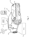
- Figure 1 shows exemplary all-electric or hybrid motor vehicle 100, according to one implementation.
- motor vehicle 100 has front end 102, rear end 104, roof 106, and exterior light arrays 116a and 116b each including multiple lighting elements 118.
- motor vehicle 100 includes battery 112, and may include optional fuel tank 114.
- remote electronic devices 110a and 110b capable of wireless communication with motor vehicle 100.
- remote electronic device 110a is a wireless key fob of motor vehicle 100
- remote electronic device 110b is a mobile phone; however, any other remote electronic device capable of transmitting radio frequency (“RF") signals or other types of signals could be used.
- RF radio frequency
- remote electronic device 110b may include SOC control application 111 for execution by a hardware processor (hardware processor of remote electronic device 110b not shown in Figure 1 ).
- a hardware processor hardware processor of remote electronic device 110b not shown in Figure 1 .
- remote electronic device 110b includes computing resources sufficient to store and execute SOC control application 111, remote electronic device 110b and SOC control application 111 can be utilized to program motor vehicle 100 to charge battery 112 during one or more desired charging intervals, such as during off-peak hours.
- battery may refer to a battery pack including multiple secondary battery cells suitable for use in providing power for propulsion of motor vehicle 100. That is to say, battery 112 may be implemented as a high voltage battery pack including multiple nickel-metal hydride (NiMH), molten-salt, or lithium-ion battery cells, for example, and capable of generating hundreds of volts.
- NiMH nickel-metal hydride
- motor vehicle 100 is depicted as an all-electric or hybrid automobile in Figure 1 , that representation is merely exemplary. More generally, motor vehicle 100 may take the form of an all-electric or hybrid automobile, truck, cart, track propelled vehicle, boat, or drone, to name a few examples.
- exterior light arrays 116a and 116b may be situated at or near front end 102 of motor vehicle 100.
- Each of exterior light arrays 116a and 116b includes multiple lighting elements 118, which may be implemented using light-emitting diodes (LEDs), for example.
- LEDs light-emitting diodes
- exterior light arrays 116a and 116b may be utilized as part of an SOC display system for displaying the SOC of battery 112, as well as to provide general lighting for motor vehicle 100 when not displaying the SOC of battery 112.
- exterior light arrays 116a and 116b may be headlamp arrays of motor vehicle 100, may provide turn signal lighting for motor vehicle 100, or may be implemented as daytime running lights for motor vehicle 100.
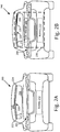
- Figure 2A is a rear view of motor vehicle 200 showing exterior light array 220 as a brake light array of motor vehicle 200, according to one implementation.
- Figure 2A shows rear end 204 and roof 206 of motor vehicle 200, as well as exterior light array 220 (hereinafter “brake light array 220") including multiple lighting elements 218.
- brake light array 220 is situated proximate to or on rear window 208 of motor vehicle 200.
- brake light array 220 is implemented as a center high mounted stop lamp (CHMSL).
- CHMSL center high mounted stop lamp
- first end 222 and second end 224 of brake light array 220 are well as battery 212 of motor vehicle 200.
- Motor vehicle 200 including rear end 204, roof 206, rear window 208, and brake light array 220 corresponds in general to motor vehicle 100, in Figure 1 , and those corresponding features may share any of the characteristics attributed to either corresponding feature in the present disclosure. That is to say, although not shown in Figure 1 , motor vehicle 100 may include features corresponding respectively to rear window 208 and brake light array 220. Moreover, although not shown in Figure 2A , motor vehicle 200 may include features corresponding respectively to front end 102, optional fuel tank 114, and exterior light arrays 116a and 116b. In addition, like motor vehicle 110, motor vehicle 210 may be capable of wireless communication with a remote electronic device corresponding to either or both of key fob 110a and mobile phone 110b, in Figure 1 .
- Battery 212 corresponds in general to battery 112, in Figure 1 , and those corresponding features may share any of the characteristics attributed to either corresponding feature in the present disclosure.
- battery 212 may be implemented as a high voltage battery pack including multiple NiMH, molten-salt, or lithium-ion battery cells, for example, and capable of generating hundreds of volts.
- Lighting elements 218, in Figure 2A can correspond in general to lighting elements 118, in Figure 1 , and those corresponding features may share any of the characteristics attributed to either corresponding feature in the present disclosure.
- lighting elements 218 may be implemented using LEDs.
- brake light array 220 provides brake lighting. Consequently, the color produced by lighting elements 118/218 when illuminated may differ depending on whether they are included in exterior light arrays 116a and 116b, or brake light array 220.
- lighting elements 218 of brake light array 220 may emit red light when illuminated
- lighting elements 118 of exterior light arrays 116a and 116b may emit substantially white or amber light when illuminated, for example.
- Figure 2B shows motor vehicle 100/200 utilizing SOC display system 230 to display the SOC of battery 112/212 of motor vehicle 110/210 by brake light array 220, according to one implementation. It is noted that features identified by reference numbers identical to those shown in Figure 2A correspond respectively to those previously described features. It is further noted that not all features common to Figures 2A and 2B are identified by reference numbers in both figures. For example, in the interests of clarity, respective first and second ends 222 and 224 of brake light array 220 are present in both Figures 2A and 2B , but are identified by reference numbers 222 and 224 only in Figure 2A .
- SOC display system 230 utilized in the exemplary implementation shown in Figure 2B includes battery 112/212, SOC module 240, which is described in greater detail below, and brake light array 220.
- SOC display system 230 may include battery 112/212, fuel tank 114, SOC module 240, and brake light array 220.
- SOC display system 230 may include fuel tank 114 and/or battery 112/212, SOC module 240, and one or both of exterior light arrays 116a and 116b.
- SOC display system 230 including battery 112/212, SOC module 240, and brake light array 220 enables display of the SOC of battery 112/212 using brake light array 220.
- brake light array 220 when brake light array 220 is used during braking, substantially all lighting elements 218 of brake light array 220 are concurrently illuminated, as shown in Figure 2A .
- brake light array 220 when brake light array 220 is used by SOC display system 230 including SOC module 240 to display the SOC of battery 112/212, a subset of lighting elements 218 of brake light array 220 corresponding to the SOC of battery 112/212 is illuminated.
- a subset of lighting elements 218 corresponding to the percent SOC of battery 112/212 may be illuminated, beginning at first end 222 of brake light array 220 and extending toward second end 224 as far as intermediate lighting element 226.
- lighting elements 218 situated between intermediate lighting element 226 and second end 224 of brake light array 220 may remain off while lighting elements 218 from first end 222 of brake light array 220 to intermediate lighting element 226 are illuminated.
- the percentage of the number of lighting elements 218 illuminated to display the SOC of battery 112/212 may substantially match the percent SOC of battery 112/212.
- the SOC of battery 112/212 is 80%
- approximately 80% of sequential lighting elements of lighting elements 118/218 beginning at first end 222 of brake light array 220 may be illuminated to display the SOC of battery 112/212.
- brake light array 220 includes sixty (60) lighting elements 218, for instance, the first 48 of lighting elements 218 of brake light array 220 beginning from first end 222 may be illuminated to display an 80% SOC of battery 112/212.
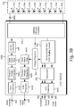
- FIG 3A shows exemplary SOC module 340A and exterior light array 320 suitable for use as part of SOC display system 230, in Figure 2B , according to one implementation.
- SOC module 340A corresponds in general to SOC module 240, and those corresponding features may share any of the characteristics attributed to either corresponding feature by the present disclosure.
- Exterior light array 320 including lighting elements 318a, 318b, 318c, 318d, 318e, 318f, 318g, 318h, 318i, and 318j (hereinafter "lighting elements 318a-318j") is shown and will be described as corresponding to brake light array 220, in Figures 2A and 2B , in the interest of clarity.
- exterior light array 320 can correspond to any of exterior light arrays 116a or 116b, or brake light array 220.
- each of lighting elements 318a-318j may represent multiple individual lighting elements 118/218.
- each of lighting elements 318a-318j may correspond to from 5 to 10 LED lights.
- SOC module 240/340A may receive inputs in the form of brake override signal 332, power input 334, activation signal 336, and battery status signal 338.
- Brake override signal 332 is generated when a braking system of motor vehicle 100/200 is activated, for example, when an operator of motor vehicle 100/200 applies the brakes of motor vehicle 100/200.
- Brake override signal 332 is received by electrostatic discharge (ESD) protection block 342a of SOC module 240/340A, and further passes through reverse voltage protection block 344a, input noise filter 346a, and DC/DC converter 348, before being provided as an input to lighting element controller 358.
- ESD electrostatic discharge
- Power input 334 provides power for energizing various components of SOC module 240/340A, such as microcontroller unit 356, which may serve as the SOC display controller of SOC module 240/340A, and lighting element controller 358, which controls the illumination of lighting elements 318a-318j.
- Power input 334 is received by ESD protection block 342b, and further passes through reverse voltage protection block 344b, input noise filter 346b, and voltage regulator 352, which may be a low-dropout regulator, for example, before being provided as an input to each of microcontroller unit 356 and lighting element controller 358.
- Activation signal 336 and battery status signal 338 are used by microcontroller unit 356 and lighting element controller 358 to generate display signal 386a.
- Display signal 386a causes some or all of lighting elements 318a-318j (shown as 218 in Figures 2A and 2B ) to be illuminated for displaying the SOC of battery 112/212 by exterior light array/brake light array 320 (hereinafter "brake light array 320").
- activation signal 336 and battery status signal 338 are received by microcontroller unit 356 via ESD protection block 342c and transceiver 350. It is noted that, in various implementations, activation signal 336 and battery status signal 338 may be received as wired or wireless inputs to SOC module 240/340A.
- display signal 386a is generated and provided as an output by SOC module 240/340A based on activation signal 336 and battery status signal 338.
- Battery status signal 338 includes the SOC of battery 112/212 and may be received by SOC module 240/340A from battery 112/212 of motor vehicle 100/200.
- Activation signal 336 may be generated in a number of different ways. For example, activation signal 336 may be generated automatically when motor vehicle 100/200 including SOC display system 230 is plugged in to an external source of electric power. Alternatively, or in addition, activation signal 336 may be generated in response to a wireless signal received from remote electronic device 110a or 110b. That is to say, in some implementations, activation signal 336 may be generated in response to a wireless signal received from key fob 110a of motor vehicle 100/200, or from mobile phone 110b.
- activation signal 336 is generated in response to a wireless signal received from remote electronic device 110a or 110b
- that wireless signal may be received due to a manual input to remote electronic device 110a or 110b by a user in possession of remote electronic device 110a or 110b.
- the wireless signal to which generation of activation signal 336 is responsive may be received automatically from remote electronic device 110a or 110b, due to proximity of remote electronic device 110a or 110b to motor vehicle 100/200.
- Lighting element controller 358 of SOC module 240/340A provides display signal 386a as an output causing some or all of lighting elements 318a-318j (shown as 218 in Figures 2A and 2B ) to be selectively illuminated. It is emphasized, however, that brake override signal 332 has preferential control over display signal 386a. As a result, lighting element controller 358 is configured to preferentially provide brake override signal 332 for illuminating substantially all of lighting elements 318a-318j (shown as 218 in Figures 2A and 2B ), as an output to brake light array 220/320, through display signal 386a, in response to receiving brake override signal 332 with or without power input 334.
- FIG. 3B shows exemplary SOC module 340B and brake light array 320 suitable for use as part of SOC display system 230, in Figure 2B , according to another implementation.
- SOC module 340B corresponds in general to SOC module 240, in Figure 2 , and those corresponding features may share any of the characteristics attributed to either corresponding feature in the present disclosure.
- the features of SOC module 340B identified by reference numbers identical to those shown in Figure 3A correspond respectively to those previously described features and may share any of the characteristics attributed to those corresponding features in the present disclosure.
- brake light array 320 the array of lighting elements 318a-318j is described as brake light array 320 in the interest of clarity, in other implementations, the functionality attributed to brake light array 320 may be provided by exterior light array 116a and/or 116b, in Figure 1 .
- exemplary SOC module 240/340B is shown to receive an additional input in the form of fuel status signal 388.
- fuel status signal 388 is received by SOC module 240/340B via ESD protection block 342c and transceiver 350, and may be received as a wired or wireless input to SOC module 240/340B.
- Fuel status signal 388 may be received from optional fuel tank 114 of motor vehicle 100/200, and may correspond to a fuel supply in fuel tank 114.
- Microcontroller unit 356 of SOC module 240/340B receives activation signal 336, battery status signal 338, and fuel status signal 388 from transceiver 350.
- display signal 386b is generated and provided as an output by SOC module 240/340B based on activation signal 336, battery status signal 338, and fuel status signal 388.
- Display signal 386b causes some of lighting elements 318a-318j (shown as 218 in Figures 2A and 2B ) to be illuminated for displaying the SOC of battery 112/212 by brake light array 320.
- display signal 386b causes some others of lighting elements 318a-318j (shown as 218 in Figures 2A and 2B ) to be illuminated for displaying the fuel supply of fuel tank 114 by brake light array 320.
- a first subset of lighting elements 218/318a-318j including half of those lighting elements e.g., lighting elements 318a, 318b, 318c, 318d, and 318e (hereinafter “lighting elements 318a-318e”) may be used to display the SOC of battery 112/212.
- a second subset of lighting elements 218/318a-318j including the other half of those lighting elements e.g., lighting elements 318f, 318g, 318h, 318i, and 318j (hereinafter “lighting elements 318f-318j"
- lighting elements 318f-318j may be used to display the fuel supply of fuel tank 114.
- display signal 386b provided as an output from SOC module 240/340B causes some or all of first subset of lighting elements 318a-318e to be selectively illuminated to display the SOC of battery 112/212.
- Display signal 386b also causes some or all of second subset of lighting elements 318f-318j to be selectively illuminated to display the fuel supply of fuel tank 114. It is emphasized, however, that brake override signal 332 has preferential control over display signal 386b.
- lighting element controller 358 is configured to preferentially provide brake override signal 332 for illuminating substantially all of lighting elements 218/318a-318j, as an output brake light array 220/320, through display signal 386b, in response to receiving brake override signal 332 with or without power input 334.
- Figure 4A shows lighting element illumination patterns provided by SOC display system 230, in Figure 2 , during various display modes, while Figure 4B shows SOC illumination patterns provided by that system during an SOC display stage, according to one implementation.
- Table 400A of Figure 4A and table 400B of Figure 4B show lighting element illumination patterns displayed by brake light array 420 in response to different SOC display criteria.
- those SOC display criteria can include no display mode 460a resulting in non-illumination pattern 460b, and mode 462a corresponding to an initiation stage immediately following plug in (also referred to as "immediate plug-in recognition mode"), or to a plug in state in which the external source of electric power is not charging the battery due to scheduling criteria or the external source being offline, resulting in illumination pattern 462b.
- the display criteria shown by table 400A includes SOC display mode 464, which can result in illumination patterns corresponding to the measured SOC of the battery and represented in table 400A by exemplary 80% SOC illumination pattern 466h.
- charging fault mode 468a in which motor vehicle 100/200 is plugged in to an external source of electric power but not charging properly, resulting in illumination pattern 468b.
- the SOC display criteria can include a variety of SOC charge states 464a, 464b, 464c, 464d, 464e, 464f, 464g, 464h, 464i, and 464j (hereinafter "SOC charge states 46aa-464j") in which motor vehicle 100/200 including battery 112/212 is plugged in to an external source of electric power.
- SOC charge states 46aa-464j SOC charge states 46aa-464j
- table 400B shows SOC illumination patterns 466a, 466b, 466c, 466d, 466e, 466f, 466g, 466h, 466i, and 466j (hereinafter "SOC illumination patterns 466a-466j") corresponding respectively to SOC charge states 464a-464j.
- Figure 4A also shows activation signal 436 for display modes 460a, 462a, 464, and 468a.
- Activation signal 436 in Figure 4A , corresponds in general to activation signal 336, in Figures 3A and 3B , and may share any of the characteristics attributed to that corresponding feature in the present disclosure.
- activation signal 336/436 has a low or substantially zero value for no display mode 460a, resulting in non-illumination pattern 460b.
- activation signal 336/436 has a value of substantially 20% of duty cycle for mode 462a, substantially 30% of duty cycle for SOC display mode 464 (i.e., all of SOC charge states 464a-464j), and substantially 40% of duty cycle for charging fault mode 468a.
- SOC display system 230 indicates that it is in an evaluation mode due to activation signal 436 just being turned on in response to a plug in event or in response to a wireless signal received from a key fob or from a mobile phone being carried by a user. While evaluation is in progress, only the central few lighting elements 218/318a-318j are illuminated, as shown by illumination pattern 462b in Figure 4A , to indicate that SOC display system 230 is in an evaluation or initiation mode.
- lighting elements 218/318a-318j may be illuminated according to the actual SOC of the battery, i.e. transition may be made to one of the SOC illumination patterns 466a-466j or to fault illumination pattern 468b displayed by brake light array 220/320/420.
- illumination pattern 462b persists after the initiation stage.
- the initiation stage of the SOC display system may last approximately ten seconds before transition is made to one of SOC illumination patterns 466a-466j or fault illumination pattern 468b displayed by brake light array 220/320/420.
- illumination pattern 462b, SOC illumination patterns 466a-466j, or fault illumination pattern 468b displayed by brake light array 220/320/420 remain on for only a predetermined amount of time, such as 45 seconds or a few minutes, and then turn off until the next SOC illumination pattern needs to be displayed (for example, to show an increase in the percentage of battery charge) or unless turned on again by user demand (such as use of the key fob or the mobile phone).
- illumination pattern 462b, SOC illumination patterns 466a-466j, or fault illumination pattern 468b displayed by brake light array 220/320/420 remain on for as long as the vehicle is plugged in.
- Brake light array 420 in Figures 4A and 4B , corresponds in general to brake light array 220/320 in Figures 2A, 2B , 3A , and 3B , and those corresponding features may share the characteristics attributed to any of the corresponding features in the present disclosure.
- the exemplary lighting element illumination patterns shown in Figures 4A and 4B correspond to implementations of SOC display system 230 in which SOC module 240 takes the form of SOC module 340A, shown in Figure 3A .
- the exemplary lighting element illumination patterns displayed by SOC display system 230 during the SOC display stage shown in Figure 4B display the SOC of battery 112/212 by brake light array 220/320/420, but not the fuel supply of fuel tank 114.
- the same illumination pattern i.e., illumination pattern 462b
- illumination pattern 462b is shown for all SOC display criteria with the exception of no display 460a. That is to say, no display SOC display criterion 460a results in non-illumination pattern 460b of lighting elements 218/318a-318j. All other SOC display criteria, i.e., SOC charge states 464a-464j and a fault state result in display of illumination pattern 462b in which only a central subset of lighting elements 218/318a-318j are illuminated during the initiation stage of SOC display system 230.
- illumination pattern 462b may include illumination of a central 20% of lighting elements 218/318a-318j during the initiation stage. Referring to Figure 3A , for instance, illumination pattern 462b may result in lighting elements 318e and 318f being illuminated, while lighting elements 318a, 318b, 318c, 318d, 318g, 318h, 318i, and 318j are off.
- illumination pattern 462b may correspond uniquely to mode 462a during the SOC display stage, while all other SOC display criteria, i.e., SOC charge states 464a-464j and charging fault mode 468a result in different respective illumination patterns.
- SOC charge state 464a is shown to correspond to a 10% SOC of battery 112/212 during charging.
- SOC illumination pattern 466a for SOC charge state 464a during the SOC display stage of SOC display system 230 results in approximately 10% of lighting elements 218/318a-318j being illuminated.
- SOC illumination pattern 466a may include illumination of approximately 10% of consecutive lighting elements of lighting elements 218/318a-318j, beginning at first end 222 of brake light array 220/320, during the SOC display stage.
- SOC illumination pattern 466a may result in lighting element 318a being illuminated, while lighting elements 318b, 318c, 318d, 318e, 318f, 318g, 318h, 318i, and 318j are off.
- SOC charge state 464b is shown to correspond to a 20% SOC of battery 112/212 during charging.
- SOC illumination pattern 466b for SOC charge state 464b during the SOC display stage of SOC display system 230 results in approximately 20% of lighting elements 218/318a-318j being illuminated.
- SOC illumination pattern 466b may include illumination of approximately 20% of consecutive lighting elements of lighting elements 218/318a-318j, beginning at first end 222 of brake light array 220/320, during the SOC display stage.
- SOC illumination pattern 466b may result in lighting elements 318a and 318b being illuminated, while lighting elements 318c, 318d, 318e, 318f, 318g, 318h, 318i, and 318j are off.
- SOC charge state 464c is shown to correspond to a 30% SOC of battery 112/212 during charging.
- SOC illumination pattern 466c for SOC charge state 464c during the SOC display stage of SOC display system 230 results in approximately 30% of lighting elements 218/318a-318j being illuminated.
- SOC illumination pattern 466c may include illumination of approximately 30% of consecutive lighting elements of lighting elements 218/318a-318j, beginning at first end 222 of brake light array 220/320, during the SOC display stage.
- SOC illumination pattern 466c may result in lighting elements 318a, 318b, and 318c being illuminated, while lighting elements 318d, 318e, 318f, 318g, 318h, 318i, and 318j are off.
- SOC charge state 464d is shown to correspond to a 40% SOC of battery 112/212 during charging.
- SOC illumination pattern 466d for SOC charge state 464d during the SOC display stage of SOC display system 230 results in approximately 40% of lighting elements 218/318a-318j being illuminated.
- SOC illumination pattern 466d may include illumination of approximately 40% of consecutive lighting elements of lighting elements 218/318a-318j, beginning at first end 222 of brake light array 220/320, during the SOC display stage.
- SOC illumination pattern 466d may result in lighting elements 318a, 318b, 318c, and 318d being illuminated, while lighting elements 318e, 318f, 318g, 318h, 318i, and 318j are off.
- SOC charge state 464e is shown to correspond to a 50% SOC of battery 112/212 during charging.
- SOC illumination pattern 466e for SOC charge state 464e during the SOC display stage of SOC display system 230 results in approximately 50% of lighting elements 218/318a-318j being illuminated.
- SOC illumination pattern 466e may include illumination of approximately 50% of consecutive lighting elements of lighting elements 218/318a-318j, beginning at first end 222 of brake light array 220/320, during the SOC display stage.
- SOC illumination pattern 466e may result in lighting elements 318a, 318b, 318c, 318d, and 318e being illuminated, while lighting elements 318f, 318g, 318h, 318i, and 318j are off.
- SOC charge state 464f is shown to correspond to a 60% SOC of battery 112/212 during charging.
- SOC illumination pattern 466f for SOC charge state 464f during the SOC display stage of SOC display system 230 results in approximately 60% of lighting elements 218/318a-318j being illuminated.
- SOC illumination pattern 466f may include illumination of approximately 60% of consecutive lighting elements of lighting elements 218/318a-318j, beginning at first end 222 of brake light array 220/320, during the SOC display stage.
- SOC illumination pattern 466f may result in lighting elements 318a, 318b, 318c, 318d, 318e, and 318f being illuminated, while lighting elements 318g, 318h, 318i, and 318j are off.
- SOC charge state 464g is shown to correspond to a 70% SOC of battery 112/212 during charging.
- SOC illumination pattern 466g for SOC charge state 464g during the SOC display stage of SOC display system 230 results in approximately 70% of lighting elements 218/318a-318j being illuminated.
- SOC illumination pattern 466g may include illumination of approximately 70% of consecutive lighting elements of lighting elements 218/318a-318j, beginning at first end 222 of brake light array 220/320, during the SOC display stage.
- SOC illumination pattern 466f may result in lighting elements 318a, 318b, 318c, 318d, 318e, 318f, and 318g being illuminated, while lighting elements 318h, 318i, and 318j are off.
- SOC charge state 464h is shown to correspond to an 80% SOC of battery 112/212 during charging.
- SOC illumination pattern 466h for SOC charge state 464h during the SOC display stage of SOC display system 230 results in approximately 80% of lighting elements 218/318a-318j being illuminated.
- SOC illumination pattern 466h may include illumination of approximately 80% of consecutive lighting elements of lighting elements 218/318a-318j, beginning at first end 222 of brake light array 220/320, during the SOC display stage.
- SOC illumination pattern 466h may result in lighting elements 318a, 318b, 318c, 318d, 318e, 318f, 318g, and 318h being illuminated, while lighting elements 318i and 318j are off.
- SOC charge state 464i is shown to correspond to a 90% SOC of battery 112/212 during charging.
- SOC illumination pattern 466i for SOC charge state 464i during the SOC display stage of SOC display system 230 results in approximately 90% of lighting elements 218/318a-318j being illuminated.
- SOC illumination pattern 466i may include illumination of approximately 90% of consecutive lighting elements of lighting elements 218/318a-318j, beginning at first end 222 of brake light array 220/320, during the SOC display stage.
- SOC illumination pattern 466i may result in lighting elements 318a, 318b, 318c, 318d, 318e, 318f, 318g, 318h, and 318i being illuminated, while lighting element 318j is off.
- SOC charge state 464j is shown to correspond to a 100% SOC of battery 112/212 during charging.
- SOC illumination pattern 466j for SOC charge state 464j during the SOC display stage of SOC display system 230 results in substantially 100% of lighting elements 218/318a-318j being illuminated.
- SOC illumination pattern 466j may include illumination of substantially 100% of consecutive lighting elements of lighting elements 218/318a-318j, beginning at first end 222 of brake light array 220/320, during the SOC display stage. Referring to Figure 3A , for instance, SOC illumination pattern 466j may result in all of lighting elements 318a-318j being illuminated.
- Charging fault mode 468a is shown to correspond to a fault state during charging of battery 112/212.
- Fault illumination pattern 468b for fault mode 468a during the SOC display stage of SOC display system 230 results in lighting elements 218/318a-318j being illuminated in a non-continuous pattern.
- fault illumination pattern 468b may include illumination of sequences of approximately 10% of consecutive lighting elements of lighting elements 218/318a-318j alternating with sequences of approximately 10% of consecutive lighting elements of lighting elements 218/318a-318j that are off during the SOC display stage.
- fault illumination pattern 468b may result in alternate lighting elements 318a, 318c, 318e, 318g, and 318i being illuminated, while intervening alternate lighting elements 318b, 318d, 318f, 318h, and 318j are off.
- SOC display system 230 indicates that it is in an evaluation mode due to activation signal 336/436 just being turned on in response to a plug in event or in response to a wireless signal received from a key fob or from a mobile phone being carried by a user. While evaluation is in progress, only the central few lighting elements 218/318a-318j are illuminated as shown in Figure 4A to indicate that the SOC display system is in an evaluation or initiation mode. After passage of a predetermined period of time, such as several seconds, when evaluation of SOC of the battery is complete, lighting elements 218/318a-318j are illuminated according to the actual SOC of the battery, i.e. transition is made to one of SOC illumination patterns 466a-466j, or fault illumination pattern 468b is displayed, or illumination pattern 462b continues to be displayed by brake light array 220/320/420.
- a predetermined period of time such as several seconds
- the initiation stage of the SOC display system may last approximately ten seconds, during which time illumination pattern 462b is displayed. After the initiation stage, e.g., after ten second, illumination pattern 462b may continue to be displayed, or transition may be made to one of SOC illumination patterns 466a-466j or fault illumination pattern 468b.
- illumination pattern 462b, SOC illumination patterns 466a-466j, or fault illumination pattern 468b displayed by brake light array 220/320/420 remain on for only a predetermined amount of time, such as 45 seconds or a few minutes, and then turn off until the next SOC illumination pattern needs be displayed (for example, to show an increase in the percentage of battery charge) or unless turned on again by user demand (such as use of the key fob or the mobile phone).
- illumination pattern 462b, SOC illumination patterns 466a-466j, or fault illumination pattern 468b displayed by brake light array 220/320/420 remain on for as long as the vehicle is plugged in.
- the present application addresses the inconvenience to all-electric and plug-in hybrid motor vehicle owners and operators imposed by conventional solutions for displaying the SOC of a battery of the motor vehicle during charging.
- the present solution advantageously enables the motor vehicle owner or operator to view the SOC from a distance of many meters, such as tens of meters, for example.
- the present solution further advantageously enables display of the SOC of the battery on demand.
Landscapes
- Engineering & Computer Science (AREA)
- Mechanical Engineering (AREA)
- Transportation (AREA)
- Chemical & Material Sciences (AREA)
- Combustion & Propulsion (AREA)
- Life Sciences & Earth Sciences (AREA)
- Sustainable Development (AREA)
- Sustainable Energy (AREA)
- Power Engineering (AREA)
- Lighting Device Outwards From Vehicle And Optical Signal (AREA)
- Charge And Discharge Circuits For Batteries Or The Like (AREA)
- Electric Propulsion And Braking For Vehicles (AREA)
Description
- As the transition away from fossil fuels continues, the use of all-electric and hybrid motor vehicles grows ever more popular. Despite their many advantages, the charging of all-electric and hybrid motor vehicles can present logistical challenges. For example, the battery stack typically used in such motor vehicles can take up to several hours to fully recharge. Moreover, because the cost of electric power can vary depending upon the demands being placed on a power grid over the course of a day, it is sometimes advantageous or desirable to charge all-electric or plug-in hybrid motor vehicles during off-peak hours, such as during the evening, early morning, or overnight.
- In the conventional art, a lighted ring or other lighted indicator around the vehicle charge port, and/or interior dashboard lighting is typically used to communicate the state-of-charge (SOC) of the motor vehicle during charging. However, due to the length of time required to charge many all-electric or plug-in hybrid motor vehicles, a vehicle owner or operator will typically not remain in the immediate vicinity of the charge port, or in view of the vehicle interior, during charging. Nevertheless, the vehicle owner or operator may wish to easily and periodically check on charging status. As use of all-electric and plug-in hybrid motor vehicles becomes more widespread, there is a growing need for an SOC display solution that enables a vehicle owner or operator to view charging status with ease and at a greater distance from the motor vehicle, and to do so on demand.
-
Document DE 10 2014 222 695 A1 describes a method for indicating a charging process of an electrical energy storage device of a vehicle. The electrical energy storage device serves to supply an electrical drive motor of the vehicle with electrical energy. The vehicle comprises a lighting device which can be actuated in a first operating mode independently of the charging process. In this method, a time sequence of the charging process is determined and the time sequence of the charging process is displayed with the aid of the lighting device in a second operating mode of the lighting device. - The present invention is directed to a state-of-charge (SOC) display system, substantially as shown in and/or described in connection with at least one of the figures, and as set forth in the claims.
-
-
Figure 1 shows an exemplary all-electric or hybrid motor vehicle, according to one implementation. -
Figure 2A is a rear view of a motor vehicle showing an exterior light array of the motor vehicle, according to one implementation. -
Figure 2B shows the motor vehicle ofFigure 2A including an exemplary state-of-charge (SOC) display system utilizing the exterior light array to display the SOC of a battery of the motor vehicle, according to one implementation. -
Figure 3A shows an exemplary SOC module and exterior light array of an SOC display system, according to one implementation. -
Figure 3B shows an exemplary SOC module and exterior light array of an SOC display system, according to another implementation. -
Figure 4A shows lighting element illumination patterns provided by an SOC display system in various display modes, according to one implementation. -
Figure 4B shows lighting element illumination patterns provided by an SOC display system during an SOC display stage, according to one implementation. - Despite playing an important role in the transition away from fossil fuel powered transportation, all-electric and hybrid motor vehicles can be time consuming to charge. For example, and as stated above, the battery stack typically used in such motor vehicles can take up to several hours to fully recharge. Moreover, because the cost of electric power can vary depending upon the demands being placed on a power grid over the course of a day, it is sometimes advantageous or desirable to charge all-electric or plug-in hybrid motor vehicles during off-peak hours, such as during the evening, early morning, or overnight.
- As also stated above, in the conventional art, a lighted ring or other lighted indicator around the vehicle charge port, and/or interior dashboard lighting is typically used to communicate the state-of-charge (SOC) of the motor vehicle during charging. However, due to the time required to charge an all-electric or plug-in hybrid motor vehicle, a vehicle owner or operator will typically not remain in view of such conventional display solutions during charging, making monitoring of the charge status through use of conventional SOC displays inconvenient. Nevertheless, the vehicle owner or operator may wish to periodically check on charging status. As use of all-electric and hybrid motor vehicles becomes more widespread, there is a growing need for an SOC display solution that enables a vehicle owner or operator to view charging status at a greater distance from the motor vehicle, and to do so on demand.
- The present application addresses the inconvenience to all-electric and hybrid motor vehicle owners and operators described above. By utilizing an exterior light array of a motor vehicle to display the SOC of a battery of the vehicle during charging, the present solution advantageously enables the motor vehicle owner or operator to view the SOC from a distance of many meters, such as tens of meters, for example. Moreover, by displaying the SOC in response to a wireless signal received from a remote electronic device controlled by the motor vehicle owner or operator, the present solution further advantageously enables display of the SOC of the battery on demand.
-
Figure 1 shows exemplary all-electric orhybrid motor vehicle 100, according to one implementation. As shown inFigure 1 ,motor vehicle 100 hasfront end 102,rear end 104,roof 106, andexterior light arrays multiple lighting elements 118. In addition,motor vehicle 100 includesbattery 112, and may includeoptional fuel tank 114. Also shown inFigure 1 are remoteelectronic devices motor vehicle 100. According to the exemplary implementation shown inFigure 1 , remoteelectronic device 110a is a wireless key fob ofmotor vehicle 100, while remoteelectronic device 110b is a mobile phone; however, any other remote electronic device capable of transmitting radio frequency ("RF") signals or other types of signals could be used. - Nevertheless, and as further shown in
Figure 1 , in some implementations, remoteelectronic device 110b may includeSOC control application 111 for execution by a hardware processor (hardware processor of remoteelectronic device 110b not shown inFigure 1 ). As noted above, because the cost of electric power can vary depending upon the demands being placed on a power grid over the course of a day, it may be advantageous or desirable to chargemotor vehicle 100 during off-peak hours, such as during the evening, early morning, or overnight. Consequently, where remoteelectronic device 110b includes computing resources sufficient to store and executeSOC control application 111, remoteelectronic device 110b andSOC control application 111 can be utilized to programmotor vehicle 100 to chargebattery 112 during one or more desired charging intervals, such as during off-peak hours. - It is noted that, as used in the present application, "battery" may refer to a battery pack including multiple secondary battery cells suitable for use in providing power for propulsion of
motor vehicle 100. That is to say,battery 112 may be implemented as a high voltage battery pack including multiple nickel-metal hydride (NiMH), molten-salt, or lithium-ion battery cells, for example, and capable of generating hundreds of volts. It is further noted that althoughmotor vehicle 100 is depicted as an all-electric or hybrid automobile inFigure 1 , that representation is merely exemplary. More generally,motor vehicle 100 may take the form of an all-electric or hybrid automobile, truck, cart, track propelled vehicle, boat, or drone, to name a few examples. - As shown in
Figure 1 ,exterior light arrays front end 102 ofmotor vehicle 100. Each ofexterior light arrays multiple lighting elements 118, which may be implemented using light-emitting diodes (LEDs), for example. According to the inventive principles disclosed in the present application,exterior light arrays battery 112, as well as to provide general lighting formotor vehicle 100 when not displaying the SOC ofbattery 112. For example,exterior light arrays motor vehicle 100, may provide turn signal lighting formotor vehicle 100, or may be implemented as daytime running lights formotor vehicle 100. -
Figure 2A is a rear view ofmotor vehicle 200 showingexterior light array 220 as a brake light array ofmotor vehicle 200, according to one implementation.Figure 2A showsrear end 204 androof 206 ofmotor vehicle 200, as well as exterior light array 220 (hereinafter "brake light array 220") includingmultiple lighting elements 218. It is noted thatbrake light array 220 is situated proximate to or onrear window 208 ofmotor vehicle 200. Moreover, according to the exemplary representation shown inFigure 2A , as well as in subsequentFigure 2B ,brake light array 220 is implemented as a center high mounted stop lamp (CHMSL). Also shown inFigure 2A , arefirst end 222 andsecond end 224 ofbrake light array 220, as well asbattery 212 ofmotor vehicle 200. -
Motor vehicle 200 includingrear end 204,roof 206,rear window 208, andbrake light array 220 corresponds in general tomotor vehicle 100, inFigure 1 , and those corresponding features may share any of the characteristics attributed to either corresponding feature in the present disclosure. That is to say, although not shown inFigure 1 ,motor vehicle 100 may include features corresponding respectively torear window 208 andbrake light array 220. Moreover, although not shown inFigure 2A ,motor vehicle 200 may include features corresponding respectively tofront end 102,optional fuel tank 114, andexterior light arrays key fob 110a andmobile phone 110b, inFigure 1 . -
Battery 212 corresponds in general tobattery 112, inFigure 1 , and those corresponding features may share any of the characteristics attributed to either corresponding feature in the present disclosure. In other words, likebattery 112,battery 212 may be implemented as a high voltage battery pack including multiple NiMH, molten-salt, or lithium-ion battery cells, for example, and capable of generating hundreds of volts. -
Lighting elements 218, inFigure 2A , can correspond in general tolighting elements 118, inFigure 1 , and those corresponding features may share any of the characteristics attributed to either corresponding feature in the present disclosure. In other words, likelighting elements 118,lighting elements 218 may be implemented using LEDs. However, it is noted that althoughexterior light arrays lighting elements 118 provide general lighting formotor vehicle 100/200,brake light array 220 provides brake lighting. Consequently, the color produced bylighting elements 118/218 when illuminated may differ depending on whether they are included inexterior light arrays brake light array 220. Specifically,lighting elements 218 ofbrake light array 220 may emit red light when illuminated, whilelighting elements 118 of exteriorlight arrays -
Figure 2B showsmotor vehicle 100/200 utilizingSOC display system 230 to display the SOC ofbattery 112/212 of motor vehicle 110/210 bybrake light array 220, according to one implementation. It is noted that features identified by reference numbers identical to those shown inFigure 2A correspond respectively to those previously described features. It is further noted that not all features common toFigures 2A and 2B are identified by reference numbers in both figures. For example, in the interests of clarity, respective first and second ends 222 and 224 ofbrake light array 220 are present in bothFigures 2A and 2B , but are identified byreference numbers Figure 2A . -
SOC display system 230 utilized in the exemplary implementation shown inFigure 2B includesbattery 112/212,SOC module 240, which is described in greater detail below, andbrake light array 220. However, in another implementation,SOC display system 230 may includebattery 112/212,fuel tank 114,SOC module 240, andbrake light array 220. In yet other implementations,SOC display system 230 may includefuel tank 114 and/orbattery 112/212,SOC module 240, and one or both of exteriorlight arrays - As shown in
Figure 2B ,SOC display system 230 includingbattery 112/212,SOC module 240, andbrake light array 220 enables display of the SOC ofbattery 112/212 usingbrake light array 220. ComparingFigures 2A and 2B , whenbrake light array 220 is used during braking, substantially alllighting elements 218 ofbrake light array 220 are concurrently illuminated, as shown inFigure 2A . By contrast, whenbrake light array 220 is used bySOC display system 230 includingSOC module 240 to display the SOC ofbattery 112/212, a subset oflighting elements 218 ofbrake light array 220 corresponding to the SOC ofbattery 112/212 is illuminated. - For example, and as shown by
Figure 2B , where the SOC ofbattery 112/212 is less than one hundred percent (100%), a subset oflighting elements 218 corresponding to the percent SOC ofbattery 112/212 may be illuminated, beginning atfirst end 222 ofbrake light array 220 and extending towardsecond end 224 as far asintermediate lighting element 226. Moreover,lighting elements 218 situated betweenintermediate lighting element 226 andsecond end 224 ofbrake light array 220 may remain off whilelighting elements 218 fromfirst end 222 ofbrake light array 220 tointermediate lighting element 226 are illuminated. - As a specific example, in one implementation, the percentage of the number of
lighting elements 218 illuminated to display the SOC ofbattery 112/212 may substantially match the percent SOC ofbattery 112/212. Thus, where the SOC ofbattery 112/212 is 80%, approximately 80% of sequential lighting elements oflighting elements 118/218 beginning atfirst end 222 ofbrake light array 220 may be illuminated to display the SOC ofbattery 112/212. Wherebrake light array 220 includes sixty (60)lighting elements 218, for instance, the first 48 oflighting elements 218 ofbrake light array 220 beginning fromfirst end 222 may be illuminated to display an 80% SOC ofbattery 112/212. -
Figure 3A showsexemplary SOC module 340A and exteriorlight array 320 suitable for use as part ofSOC display system 230, inFigure 2B , according to one implementation.SOC module 340A corresponds in general toSOC module 240, and those corresponding features may share any of the characteristics attributed to either corresponding feature by the present disclosure. Exteriorlight array 320 includinglighting elements lighting elements 318a-318j") is shown and will be described as corresponding to brakelight array 220, inFigures 2A and 2B , in the interest of clarity. However, it is noted that, more generally, exteriorlight array 320 can correspond to any of exteriorlight arrays brake light array 220. - It is also noted that although
lighting elements 318a-318j correspond in general tolighting elements 118/218, each oflighting elements 318a-318j may represent multipleindividual lighting elements 118/218. For example, when implemented as LEDs, each oflighting elements 318a-318j may correspond to from 5 to 10 LED lights. - As shown in
Figure 3A , in oneimplementation SOC module 240/340A may receive inputs in the form ofbrake override signal 332,power input 334,activation signal 336, and battery status signal 338.Brake override signal 332 is generated when a braking system ofmotor vehicle 100/200 is activated, for example, when an operator ofmotor vehicle 100/200 applies the brakes ofmotor vehicle 100/200.Brake override signal 332 is received by electrostatic discharge (ESD)protection block 342a ofSOC module 240/340A, and further passes through reversevoltage protection block 344a, inputnoise filter 346a, and DC/DC converter 348, before being provided as an input tolighting element controller 358. -
Power input 334 provides power for energizing various components ofSOC module 240/340A, such asmicrocontroller unit 356, which may serve as the SOC display controller ofSOC module 240/340A, andlighting element controller 358, which controls the illumination oflighting elements 318a-318j. Power input 334 is received byESD protection block 342b, and further passes through reversevoltage protection block 344b,input noise filter 346b, andvoltage regulator 352, which may be a low-dropout regulator, for example, before being provided as an input to each ofmicrocontroller unit 356 andlighting element controller 358. -
Activation signal 336 and battery status signal 338 are used bymicrocontroller unit 356 andlighting element controller 358 to generatedisplay signal 386a.Display signal 386a causes some or all oflighting elements 318a-318j (shown as 218 inFigures 2A and 2B ) to be illuminated for displaying the SOC ofbattery 112/212 by exterior light array/brake light array 320 (hereinafter "brake light array 320"). According to the exemplary implementation shown inFigure 3A ,activation signal 336 and battery status signal 338 are received bymicrocontroller unit 356 viaESD protection block 342c andtransceiver 350. It is noted that, in various implementations,activation signal 336 and battery status signal 338 may be received as wired or wireless inputs toSOC module 240/340A. - According to the exemplary implementation shown in
Figure 3A ,display signal 386a is generated and provided as an output bySOC module 240/340A based onactivation signal 336 and battery status signal 338. Battery status signal 338 includes the SOC ofbattery 112/212 and may be received bySOC module 240/340A frombattery 112/212 ofmotor vehicle 100/200. -
Activation signal 336 may be generated in a number of different ways. For example,activation signal 336 may be generated automatically whenmotor vehicle 100/200 includingSOC display system 230 is plugged in to an external source of electric power. Alternatively, or in addition,activation signal 336 may be generated in response to a wireless signal received from remoteelectronic device activation signal 336 may be generated in response to a wireless signal received fromkey fob 110a ofmotor vehicle 100/200, or frommobile phone 110b. - In some implementations in which
activation signal 336 is generated in response to a wireless signal received from remoteelectronic device electronic device electronic device activation signal 336 is responsive may be received automatically from remoteelectronic device electronic device motor vehicle 100/200. -
Lighting element controller 358 ofSOC module 240/340A providesdisplay signal 386a as an output causing some or all oflighting elements 318a-318j (shown as 218 inFigures 2A and 2B ) to be selectively illuminated. It is emphasized, however, thatbrake override signal 332 has preferential control overdisplay signal 386a. As a result,lighting element controller 358 is configured to preferentially providebrake override signal 332 for illuminating substantially all oflighting elements 318a-318j (shown as 218 inFigures 2A and 2B ), as an output to brakelight array 220/320, throughdisplay signal 386a, in response to receivingbrake override signal 332 with or withoutpower input 334. -
Figure 3B showsexemplary SOC module 340B andbrake light array 320 suitable for use as part ofSOC display system 230, inFigure 2B , according to another implementation.SOC module 340B corresponds in general toSOC module 240, inFigure 2 , and those corresponding features may share any of the characteristics attributed to either corresponding feature in the present disclosure. Moreover, the features ofSOC module 340B identified by reference numbers identical to those shown inFigure 3A correspond respectively to those previously described features and may share any of the characteristics attributed to those corresponding features in the present disclosure. Thus, although the array oflighting elements 318a-318j is described asbrake light array 320 in the interest of clarity, in other implementations, the functionality attributed tobrake light array 320 may be provided by exteriorlight array 116a and/or 116b, inFigure 1 . - In addition to the features shown and described by reference to
Figure 3A ,exemplary SOC module 240/340B is shown to receive an additional input in the form of fuel status signal 388. Likeactivation signal 336 and battery status signal 338, fuel status signal 388 is received bySOC module 240/340B viaESD protection block 342c andtransceiver 350, and may be received as a wired or wireless input toSOC module 240/340B. Fuel status signal 388 may be received fromoptional fuel tank 114 ofmotor vehicle 100/200, and may correspond to a fuel supply infuel tank 114. -
Microcontroller unit 356 ofSOC module 240/340B receivesactivation signal 336, battery status signal 338, and fuel status signal 388 fromtransceiver 350. According to the exemplary implementation shown inFigure 3B ,display signal 386b is generated and provided as an output bySOC module 240/340B based onactivation signal 336, battery status signal 338, and fuel status signal 388.Display signal 386b causes some oflighting elements 318a-318j (shown as 218 inFigures 2A and 2B ) to be illuminated for displaying the SOC ofbattery 112/212 bybrake light array 320. In addition, according to the present implementation,display signal 386b causes some others oflighting elements 318a-318j (shown as 218 inFigures 2A and 2B ) to be illuminated for displaying the fuel supply offuel tank 114 bybrake light array 320. - By way of example, a first subset of
lighting elements 218/318a-318j including half of those lighting elements, e.g.,lighting elements lighting elements 318a-318e") may be used to display the SOC ofbattery 112/212. According to the same example, a second subset oflighting elements 218/318a-318j including the other half of those lighting elements, e.g.,lighting elements lighting elements 318f-318j") may be used to display the fuel supply offuel tank 114. - In this example,
display signal 386b provided as an output fromSOC module 240/340B causes some or all of first subset oflighting elements 318a-318e to be selectively illuminated to display the SOC ofbattery 112/212.Display signal 386b also causes some or all of second subset oflighting elements 318f-318j to be selectively illuminated to display the fuel supply offuel tank 114. It is emphasized, however, thatbrake override signal 332 has preferential control overdisplay signal 386b. As a result,lighting element controller 358 is configured to preferentially providebrake override signal 332 for illuminating substantially all oflighting elements 218/318a-318j, as an outputbrake light array 220/320, throughdisplay signal 386b, in response to receivingbrake override signal 332 with or withoutpower input 334. -
Figure 4A shows lighting element illumination patterns provided bySOC display system 230, inFigure 2 , during various display modes, whileFigure 4B shows SOC illumination patterns provided by that system during an SOC display stage, according to one implementation. Table 400A ofFigure 4A and table 400B ofFigure 4B show lighting element illumination patterns displayed bybrake light array 420 in response to different SOC display criteria. - As shown in
Figure 4A , those SOC display criteria can include nodisplay mode 460a resulting innon-illumination pattern 460b, andmode 462a corresponding to an initiation stage immediately following plug in (also referred to as "immediate plug-in recognition mode"), or to a plug in state in which the external source of electric power is not charging the battery due to scheduling criteria or the external source being offline, resulting inillumination pattern 462b. In addition, the display criteria shown by table 400A includesSOC display mode 464, which can result in illumination patterns corresponding to the measured SOC of the battery and represented in table 400A by exemplary 80%SOC illumination pattern 466h. Also included in table 400A is chargingfault mode 468a in whichmotor vehicle 100/200 is plugged in to an external source of electric power but not charging properly, resulting inillumination pattern 468b. - As further shown in
Figure 4B , inSOC display mode 464, the SOC display criteria can include a variety of SOC charge states 464a, 464b, 464c, 464d, 464e, 464f, 464g, 464h, 464i, and 464j (hereinafter "SOC charge states 46aa-464j") in whichmotor vehicle 100/200 includingbattery 112/212 is plugged in to an external source of electric power. In addition to SOC charge states 464a-464j, table 400B showsSOC illumination patterns SOC illumination patterns 466a-466j") corresponding respectively to SOC charge states 464a-464j. - Referring to
Figure 4A, Figure 4A also showsactivation signal 436 fordisplay modes Activation signal 436, inFigure 4A , corresponds in general toactivation signal 336, inFigures 3A and3B , and may share any of the characteristics attributed to that corresponding feature in the present disclosure. As shown inFigure 4A ,activation signal 336/436 has a low or substantially zero value for nodisplay mode 460a, resulting innon-illumination pattern 460b. According to the exemplary implementation shown inFigure 4A ,activation signal 336/436 has a value of substantially 20% of duty cycle formode 462a, substantially 30% of duty cycle for SOC display mode 464 (i.e., all of SOC charge states 464a-464j), and substantially 40% of duty cycle for chargingfault mode 468a. - Referring to
Figures 4A and4B in combination and by way of overview, during the initiation stage ofmode 462a,SOC display system 230 indicates that it is in an evaluation mode due to activation signal 436 just being turned on in response to a plug in event or in response to a wireless signal received from a key fob or from a mobile phone being carried by a user. While evaluation is in progress, only the centralfew lighting elements 218/318a-318j are illuminated, as shown byillumination pattern 462b inFigure 4A , to indicate thatSOC display system 230 is in an evaluation or initiation mode. - After passage of a predetermined period of time, such as several seconds, when evaluation of SOC of the battery is complete,
lighting elements 218/318a-318j may be illuminated according to the actual SOC of the battery, i.e. transition may be made to one of theSOC illumination patterns 466a-466j or to faultillumination pattern 468b displayed bybrake light array 220/320/420. Alternatively, in instances in which plug in is outside of a scheduled charge window or the external source of electrical power is offline,illumination pattern 462b persists after the initiation stage. - As a specific example, in one implementation, following receipt of
activation signal 336/436, the initiation stage of the SOC display system may last approximately ten seconds before transition is made to one ofSOC illumination patterns 466a-466j orfault illumination pattern 468b displayed bybrake light array 220/320/420. In some implementations,illumination pattern 462b,SOC illumination patterns 466a-466j, orfault illumination pattern 468b displayed bybrake light array 220/320/420 remain on for only a predetermined amount of time, such as 45 seconds or a few minutes, and then turn off until the next SOC illumination pattern needs to be displayed (for example, to show an increase in the percentage of battery charge) or unless turned on again by user demand (such as use of the key fob or the mobile phone). In other implementations,illumination pattern 462b,SOC illumination patterns 466a-466j, orfault illumination pattern 468b displayed bybrake light array 220/320/420 remain on for as long as the vehicle is plugged in. -
Brake light array 420, inFigures 4A and4B , corresponds in general to brakelight array 220/320 inFigures 2A, 2B ,3A , and3B , and those corresponding features may share the characteristics attributed to any of the corresponding features in the present disclosure. Nevertheless, it is noted that the exemplary lighting element illumination patterns shown inFigures 4A and4B correspond to implementations ofSOC display system 230 in whichSOC module 240 takes the form ofSOC module 340A, shown inFigure 3A . In other words, the exemplary lighting element illumination patterns displayed bySOC display system 230 during the SOC display stage shown inFigure 4B , display the SOC ofbattery 112/212 bybrake light array 220/320/420, but not the fuel supply offuel tank 114. - Referring to
Figure 4A , according to one implementation, during an initiation stage ofSOC display system 230, the same illumination pattern, i.e.,illumination pattern 462b, is shown for all SOC display criteria with the exception of nodisplay 460a. That is to say, no displaySOC display criterion 460a results innon-illumination pattern 460b oflighting elements 218/318a-318j. All other SOC display criteria, i.e., SOC charge states 464a-464j and a fault state result in display ofillumination pattern 462b in which only a central subset oflighting elements 218/318a-318j are illuminated during the initiation stage ofSOC display system 230. - By way of example, in one implementation,
illumination pattern 462b may include illumination of a central 20% oflighting elements 218/318a-318j during the initiation stage. Referring toFigure 3A , for instance,illumination pattern 462b may result inlighting elements lighting elements - As shown in
Figure 4B , during an SOC display stage ofSOC display system 230 that follows the initiation stage, distinctive illumination patterns are shown for all SOC charge states 464a-464j. For example,illumination pattern 462b may correspond uniquely tomode 462a during the SOC display stage, while all other SOC display criteria, i.e., SOC charge states 464a-464j and chargingfault mode 468a result in different respective illumination patterns. -
SOC charge state 464a is shown to correspond to a 10% SOC ofbattery 112/212 during charging.SOC illumination pattern 466a forSOC charge state 464a during the SOC display stage ofSOC display system 230 results in approximately 10% oflighting elements 218/318a-318j being illuminated. For example, in one implementation,SOC illumination pattern 466a may include illumination of approximately 10% of consecutive lighting elements oflighting elements 218/318a-318j, beginning atfirst end 222 ofbrake light array 220/320, during the SOC display stage. Referring toFigure 3A , for instance,SOC illumination pattern 466a may result inlighting element 318a being illuminated, whilelighting elements -
SOC charge state 464b is shown to correspond to a 20% SOC ofbattery 112/212 during charging.SOC illumination pattern 466b forSOC charge state 464b during the SOC display stage ofSOC display system 230 results in approximately 20% oflighting elements 218/318a-318j being illuminated. For example, in one implementation,SOC illumination pattern 466b may include illumination of approximately 20% of consecutive lighting elements oflighting elements 218/318a-318j, beginning atfirst end 222 ofbrake light array 220/320, during the SOC display stage. Referring toFigure 3A , for instance,SOC illumination pattern 466b may result inlighting elements lighting elements -
SOC charge state 464c is shown to correspond to a 30% SOC ofbattery 112/212 during charging.SOC illumination pattern 466c forSOC charge state 464c during the SOC display stage ofSOC display system 230 results in approximately 30% oflighting elements 218/318a-318j being illuminated. For example, in one implementation,SOC illumination pattern 466c may include illumination of approximately 30% of consecutive lighting elements oflighting elements 218/318a-318j, beginning atfirst end 222 ofbrake light array 220/320, during the SOC display stage. Referring toFigure 3A , for instance,SOC illumination pattern 466c may result inlighting elements lighting elements -
SOC charge state 464d is shown to correspond to a 40% SOC ofbattery 112/212 during charging.SOC illumination pattern 466d forSOC charge state 464d during the SOC display stage ofSOC display system 230 results in approximately 40% oflighting elements 218/318a-318j being illuminated. For example, in one implementation,SOC illumination pattern 466d may include illumination of approximately 40% of consecutive lighting elements oflighting elements 218/318a-318j, beginning atfirst end 222 ofbrake light array 220/320, during the SOC display stage. Referring toFigure 3A , for instance,SOC illumination pattern 466d may result inlighting elements lighting elements -
SOC charge state 464e is shown to correspond to a 50% SOC ofbattery 112/212 during charging.SOC illumination pattern 466e forSOC charge state 464e during the SOC display stage ofSOC display system 230 results in approximately 50% oflighting elements 218/318a-318j being illuminated. For example, in one implementation,SOC illumination pattern 466e may include illumination of approximately 50% of consecutive lighting elements oflighting elements 218/318a-318j, beginning atfirst end 222 ofbrake light array 220/320, during the SOC display stage. Referring toFigure 3A , for instance,SOC illumination pattern 466e may result inlighting elements lighting elements -
SOC charge state 464f is shown to correspond to a 60% SOC ofbattery 112/212 during charging.SOC illumination pattern 466f forSOC charge state 464f during the SOC display stage ofSOC display system 230 results in approximately 60% oflighting elements 218/318a-318j being illuminated. For example, in one implementation,SOC illumination pattern 466f may include illumination of approximately 60% of consecutive lighting elements oflighting elements 218/318a-318j, beginning atfirst end 222 ofbrake light array 220/320, during the SOC display stage. Referring toFigure 3A , for instance,SOC illumination pattern 466f may result inlighting elements lighting elements -
SOC charge state 464g is shown to correspond to a 70% SOC ofbattery 112/212 during charging.SOC illumination pattern 466g forSOC charge state 464g during the SOC display stage ofSOC display system 230 results in approximately 70% oflighting elements 218/318a-318j being illuminated. For example, in one implementation,SOC illumination pattern 466g may include illumination of approximately 70% of consecutive lighting elements oflighting elements 218/318a-318j, beginning atfirst end 222 ofbrake light array 220/320, during the SOC display stage. Referring toFigure 3A , for instance,SOC illumination pattern 466f may result inlighting elements lighting elements -
SOC charge state 464h is shown to correspond to an 80% SOC ofbattery 112/212 during charging.SOC illumination pattern 466h forSOC charge state 464h during the SOC display stage ofSOC display system 230 results in approximately 80% oflighting elements 218/318a-318j being illuminated. For example, in one implementation,SOC illumination pattern 466h may include illumination of approximately 80% of consecutive lighting elements oflighting elements 218/318a-318j, beginning atfirst end 222 ofbrake light array 220/320, during the SOC display stage. Referring toFigure 3A , for instance,SOC illumination pattern 466h may result inlighting elements lighting elements -
SOC charge state 464i is shown to correspond to a 90% SOC ofbattery 112/212 during charging.SOC illumination pattern 466i forSOC charge state 464i during the SOC display stage ofSOC display system 230 results in approximately 90% oflighting elements 218/318a-318j being illuminated. For example, in one implementation,SOC illumination pattern 466i may include illumination of approximately 90% of consecutive lighting elements oflighting elements 218/318a-318j, beginning atfirst end 222 ofbrake light array 220/320, during the SOC display stage. Referring toFigure 3A , for instance,SOC illumination pattern 466i may result inlighting elements element 318j is off. -
SOC charge state 464j is shown to correspond to a 100% SOC ofbattery 112/212 during charging.SOC illumination pattern 466j forSOC charge state 464j during the SOC display stage ofSOC display system 230 results in substantially 100% oflighting elements 218/318a-318j being illuminated. For example, in one implementation,SOC illumination pattern 466j may include illumination of substantially 100% of consecutive lighting elements oflighting elements 218/318a-318j, beginning atfirst end 222 ofbrake light array 220/320, during the SOC display stage. Referring toFigure 3A , for instance,SOC illumination pattern 466j may result in all oflighting elements 318a-318j being illuminated. - Charging
fault mode 468a is shown to correspond to a fault state during charging ofbattery 112/212.Fault illumination pattern 468b forfault mode 468a during the SOC display stage ofSOC display system 230 results inlighting elements 218/318a-318j being illuminated in a non-continuous pattern. For example, in one implementation,fault illumination pattern 468b may include illumination of sequences of approximately 10% of consecutive lighting elements oflighting elements 218/318a-318j alternating with sequences of approximately 10% of consecutive lighting elements oflighting elements 218/318a-318j that are off during the SOC display stage. Referring toFigure 3A , for instance,fault illumination pattern 468b may result inalternate lighting elements alternate lighting elements - In summary, during the initiation stage of
SOC display system 230,SOC display system 230 indicates that it is in an evaluation mode due toactivation signal 336/436 just being turned on in response to a plug in event or in response to a wireless signal received from a key fob or from a mobile phone being carried by a user. While evaluation is in progress, only the centralfew lighting elements 218/318a-318j are illuminated as shown inFigure 4A to indicate that the SOC display system is in an evaluation or initiation mode. After passage of a predetermined period of time, such as several seconds, when evaluation of SOC of the battery is complete,lighting elements 218/318a-318j are illuminated according to the actual SOC of the battery, i.e. transition is made to one ofSOC illumination patterns 466a-466j, orfault illumination pattern 468b is displayed, orillumination pattern 462b continues to be displayed bybrake light array 220/320/420. - As a specific example, in one implementation, following receipt of
activation signal 336/436, the initiation stage of the SOC display system may last approximately ten seconds, during whichtime illumination pattern 462b is displayed. After the initiation stage, e.g., after ten second,illumination pattern 462b may continue to be displayed, or transition may be made to one ofSOC illumination patterns 466a-466j orfault illumination pattern 468b. In some implementations, after the initiation stage elapses,illumination pattern 462b,SOC illumination patterns 466a-466j, orfault illumination pattern 468b displayed bybrake light array 220/320/420 remain on for only a predetermined amount of time, such as 45 seconds or a few minutes, and then turn off until the next SOC illumination pattern needs be displayed (for example, to show an increase in the percentage of battery charge) or unless turned on again by user demand (such as use of the key fob or the mobile phone). In other implementations,illumination pattern 462b,SOC illumination patterns 466a-466j, orfault illumination pattern 468b displayed bybrake light array 220/320/420 remain on for as long as the vehicle is plugged in. - Thus, the present application addresses the inconvenience to all-electric and plug-in hybrid motor vehicle owners and operators imposed by conventional solutions for displaying the SOC of a battery of the motor vehicle during charging. By utilizing an exterior light array of the motor vehicle to display the SOC of the battery during charging, the present solution advantageously enables the motor vehicle owner or operator to view the SOC from a distance of many meters, such as tens of meters, for example. Moreover, by displaying the SOC in response to a wireless signal received from a remote electronic device controlled by the motor vehicle owner or operator, the present solution further advantageously enables display of the SOC of the battery on demand.
Claims (11)
- A state-of-charge, SOC, display system (230) comprising:a battery (112; 212);a brake light array (220; 320; 420) including a plurality of lighting elements (218; 318a-318j); andan SOC module (240; 340B) configured to:receive a battery status signal (338), said battery status signal (338) including an SOC of said battery (112; 212);receive a fuel status signal (388) of a fuel tank (114), said fuel status signal (388) corresponding to a fuel supply in said fuel tank (114); andoutput a display signal (386b) to said brake light array (220; 320; 420) based on said battery status signal (338) and said fuel status signal (388);said brake light array (220; 320; 420) being configured to:receive said display signal (386b) from said SOC module (240; 340B);illuminate a first subset of said plurality of lighting elements (218; 318a-318j) for displaying said SOC of said battery (112; 212) by said brake light array (220; 320; 420), in response to said display signal (386b); andilluminate a second subset of said plurality of lighting elements (218; 318a-318j) for displaying said fuel supply by said brake light array (220; 320; 420), in response to said display signal (386b).
- The SOC display system (230) of claim 1, wherein said plurality of lighting elements (218; 318a-318j) comprises light-emitting diodes, LEDs.
- The SOC display system (230) of one of the preceding claims, wherein an SOC activation signal is generated to activate said SOC module (240; 2340B)
when a motor vehicle (100; 200) including said SOC display system (230) is plugged in to an external source of electric power for charging said battery (112; 212) and / or
in response to a wireless signal received from a remote electronic device (110a; 110b), wherein said remote electronic device (110a; 110b) is in particular one of a key fob and a mobile phone. - The SOC display system (230) of one of the preceding claims, wherein said SOC module (240; 340B) is further configured to turn off said subset of said plurality of lighting elements (218; 318a-318j) after a predetermined time interval.
- A motor vehicle (100; 200) comprising:a fuel tank (114); andthe SOC display system (230) of claim 1.
- The motor vehicle (100; 200) of claim 5, wherein said brake light array is situated proximate to or on a rear window of a motor vehicle and / or comprises a center high mounted stop lamp (CHMSL).
- The motor vehicle (100; 200) of claim 5 or 6, wherein said plurality of lighting elements (218; 318a-318j) comprises light-emitting diodes, LEDs.
- The motor vehicle (100; 200) of one of the claims 5 to 7, wherein an SOC activation signal is generated to activate said SOC module (240; 340B)
when said motor vehicle (100; 200) is plugged in to an external source of electric power for charging said battery (112; 212) and / or
in response to a wireless signal received from a remote electronic device (110a; 110b), wherein said remote electronic device (110a; 110b) is in particular one of a key fob and a mobile phone. - The motor vehicle of one of the claims 5 to 8, wherein said SOC module (240; 340B) is further configured to turn off said first and second subsets of said plurality of lighting elements (218; 318a-318j) after a predetermined time interval.
- A method for use by a state-of-charge, SOC, display system (230) of a motor vehicle (100; 200) including a battery (112; 212), a fuel tank (114) and a brake light array (220; 320; 420) having a plurality of lighting elements (218; 318a-318j), said method comprising:receiving a battery status signal (338) from said battery (112; 212), said battery status signal (338) including an SOC of said battery;receiving a fuel status signal (388) of said fuel tank (114), said fuel status signal (388) corresponding to a fuel supply in said fuel tank (114);outputting a display signal (386b) to said brake light array (220; 320; 420) based on said battery status signal (338) and said fuel status signal (388);illuminating a first subset of said plurality of lighting elements (218; 318a-318j) for displaying said SOC of said battery (112; 212) by said brake light array (220; 320; 420), in response to said display signal (386b); andilluminating a second subset of said plurality of lighting elements (218; 318a-318j) for displaying said fuel supply by said brake light array (220; 320; 420), in response to said display signal (386b).
- The method of claim 10, further comprising:activating said SOC display system (230) when said motor vehicle (100; 200) is plugged in to an external source of electric power for charging said battery (112; 212) and / oractivating said SOC display system (230) in response to a wireless signal received from a remote electronic device (110a; 110b).
Applications Claiming Priority (1)
| Application Number | Priority Date | Filing Date | Title |
|---|---|---|---|
| US15/883,397 US11173805B2 (en) | 2018-01-30 | 2018-01-30 | State-of-charge display system |
Publications (2)
| Publication Number | Publication Date |
|---|---|
| EP3517339A1 EP3517339A1 (en) | 2019-07-31 |
| EP3517339B1 true EP3517339B1 (en) | 2021-08-25 |
Family
ID=65036697
Family Applications (1)
| Application Number | Title | Priority Date | Filing Date |
|---|---|---|---|
| EP19152339.8A Active EP3517339B1 (en) | 2018-01-30 | 2019-01-17 | State-of-charge display system |
Country Status (3)
| Country | Link |
|---|---|
| US (1) | US11173805B2 (en) |
| EP (1) | EP3517339B1 (en) |
| CN (1) | CN110091716A (en) |
Families Citing this family (12)
| Publication number | Priority date | Publication date | Assignee | Title |
|---|---|---|---|---|
| TWI897843B (en) * | 2017-05-03 | 2025-09-21 | 美商必治妥美雅史谷比公司 | Stable formulations of fibronectin based scaffold domain proteins that bind to myostatin |
| JP7027946B2 (en) * | 2018-02-22 | 2022-03-02 | トヨタ自動車株式会社 | vehicle |
| EP3814168A1 (en) * | 2018-06-29 | 2021-05-05 | Rivian IP Holdings, LLC | Exterior light and charge indicator |
| US11580798B2 (en) | 2020-08-27 | 2023-02-14 | Nissan North America, Inc. | Vehicle lighting system |
| CN112677764B (en) * | 2020-12-31 | 2022-06-21 | 北京国家新能源汽车技术创新中心有限公司 | Method for displaying SOC of vehicle and vehicle |
| US11945329B2 (en) * | 2022-05-02 | 2024-04-02 | GM Global Technology Operations LLC | Intelligent vehicle systems and control logic for battery charge control and information display |
| FR3139631A1 (en) * | 2022-09-14 | 2024-03-15 | Psa Automobiles Sa | Indication of battery charge level by vehicle interior lighting |
| FR3141916A1 (en) * | 2022-11-15 | 2024-05-17 | Renault S.A.S | FRONT HOOD OF A MOTOR VEHICLE EQUIPPED WITH AN ELECTRIC VEHICLE CHARGING INDICATOR |
| GB2624622A (en) * | 2022-11-15 | 2024-05-29 | Mercedes Benz Group Ag | A method for indicating a charging level of an electric storage device of an at least partially electrically operated motor vehicle, computer program produc |
| US12293618B2 (en) * | 2023-08-11 | 2025-05-06 | GM Global Technology Operations LLC | Method of providing information related to status of electric vehicle |
| US12400495B2 (en) | 2023-08-11 | 2025-08-26 | GM Global Technology Operations LLC | Method of providing information related to status of electric vehicle |
| US12565118B2 (en) | 2023-08-11 | 2026-03-03 | GM Global Technology Operations LLC | Method of providing information when an electric vehicle is used as a battery pack |
Family Cites Families (15)
| Publication number | Priority date | Publication date | Assignee | Title |
|---|---|---|---|---|
| TW300957B (en) * | 1994-11-21 | 1997-03-21 | Seiko Epson Corp | |
| JP3716619B2 (en) * | 1998-05-14 | 2005-11-16 | 日産自動車株式会社 | Battery remaining capacity meter |
| US6784641B2 (en) * | 2000-09-20 | 2004-08-31 | Toshiba Battery Co., Ltd. | Uninterruptible power supply |
| KR100879515B1 (en) * | 2006-11-09 | 2009-01-22 | 삼성전자주식회사 | Method and device for displaying battery charge status of portable terminal |
| EP2240910A2 (en) * | 2008-01-09 | 2010-10-20 | Johnson Controls Technology Company | Bi-directional portable electronic device for interaction with vehicle systems |
| US8125186B2 (en) * | 2008-06-16 | 2012-02-28 | Steve Carkner | Graphic state of charge indicator for a battery charging system and method of use |
| US8606430B2 (en) * | 2010-10-08 | 2013-12-10 | GM Global Technology Operations LLC | External presentation of information on full glass display |
| JP5488708B2 (en) * | 2010-10-14 | 2014-05-14 | トヨタ自動車株式会社 | Electric vehicle display system and electric vehicle equipped with the same |
| US20120133282A1 (en) * | 2010-11-30 | 2012-05-31 | Aptera Motors, Inc. | External state of charge indicator system for an automotive vehicle |
| US20130307550A1 (en) * | 2012-05-18 | 2013-11-21 | O2Micro Inc. | State of charge indicators for battery packs |
| US20140253306A1 (en) | 2013-03-06 | 2014-09-11 | Ford Global Technologies, Llc | Electric Vehicle State of Charge Indicator Integrated With Exterior Lamps |
| US20140301101A1 (en) * | 2013-04-07 | 2014-10-09 | Mr. Derek Terrell Russ | Multifunctional Multiple Color Center High Mounted Stop Lamp |
| DE102014222695A1 (en) | 2014-04-16 | 2015-10-22 | Volkswagen Aktiengesellschaft | Displaying a charging process of an electrical energy store of a vehicle |
| JP6185945B2 (en) * | 2015-02-23 | 2017-08-23 | 株式会社Subaru | SOC display device for hybrid vehicle |
| US10240542B1 (en) * | 2017-11-20 | 2019-03-26 | Ford Global Technologies, Llc | Methods and systems for fuel system monitoring |
-
2018
- 2018-01-30 US US15/883,397 patent/US11173805B2/en not_active Expired - Fee Related
-
2019
- 2019-01-15 CN CN201910033787.4A patent/CN110091716A/en active Pending
- 2019-01-17 EP EP19152339.8A patent/EP3517339B1/en active Active
Also Published As
| Publication number | Publication date |
|---|---|
| US11173805B2 (en) | 2021-11-16 |
| EP3517339A1 (en) | 2019-07-31 |
| US20190232795A1 (en) | 2019-08-01 |
| CN110091716A (en) | 2019-08-06 |
Similar Documents
| Publication | Publication Date | Title |
|---|---|---|
| EP3517339A1 (en) | State-of-charge display system | |
| US8742907B2 (en) | Electric power information provision apparatus for an electric vehicle | |
| CN103303188B (en) | The system and method for controlling car lighting | |
| US7047120B2 (en) | Vehicle and method for controlling brake system indicators | |
| US20110043355A1 (en) | Plug-In Vehicle | |
| US20140253306A1 (en) | Electric Vehicle State of Charge Indicator Integrated With Exterior Lamps | |
| US8096673B2 (en) | Auto-controlling power saving system for solar energy street lamps | |
| US10836306B1 (en) | Vehicle with portable signature light assembly | |
| US7256514B2 (en) | Device and method for operating an electrical machine for a motor vehicle | |
| CN108422863B (en) | Light control device, vehicle with the same, and method for controlling vehicle | |
| US10427545B2 (en) | Electric vehicle supply equipment (EVSE) fault indicator systems | |
| EP3573861A1 (en) | Device for controlling an array of light sources for interior lighting of a motor vehicle passenger compartment | |
| US20140232179A1 (en) | Vehicle and method of controlling vehicle | |
| US20190329656A1 (en) | Auxiliary battery charging systems and methods for electrified vehicles | |
| US20210091582A1 (en) | Battery management apparatus for vehicle and method of the same | |
| KR20210040500A (en) | Vehicle having electric motor and method of outputting charging state for the same | |
| GB2510124A (en) | Electric vehicle with externally visible charging indication | |
| JP2017192172A (en) | Charge state display device | |
| CN206067600U (en) | Vehicle-mounted lighting device | |
| KR100598875B1 (en) | Idle stop control of parallel hybrid electric vehicle | |
| US20230123176A1 (en) | Customizable electric vehicle supply equipment systems | |
| US8140208B2 (en) | Electric drive vehicle | |
| US20230030477A1 (en) | Vehicle control unit and vehicle control system | |
| KR101289052B1 (en) | Start control system of Electric type agriculture vehicle using the low voltage battery | |
| CN111845628A (en) | Control method and control device for vehicle-mounted wireless charging system |
Legal Events
| Date | Code | Title | Description |
|---|---|---|---|
| PUAI | Public reference made under article 153(3) epc to a published international application that has entered the european phase |
Free format text: ORIGINAL CODE: 0009012 |
|
| STAA | Information on the status of an ep patent application or granted ep patent |
Free format text: STATUS: THE APPLICATION HAS BEEN PUBLISHED |
|
| AK | Designated contracting states |
Kind code of ref document: A1 Designated state(s): AL AT BE BG CH CY CZ DE DK EE ES FI FR GB GR HR HU IE IS IT LI LT LU LV MC MK MT NL NO PL PT RO RS SE SI SK SM TR |
|
| AX | Request for extension of the european patent |
Extension state: BA ME |
|
| STAA | Information on the status of an ep patent application or granted ep patent |
Free format text: STATUS: REQUEST FOR EXAMINATION WAS MADE |
|
| 17P | Request for examination filed |
Effective date: 20200130 |
|
| RBV | Designated contracting states (corrected) |
Designated state(s): AL AT BE BG CH CY CZ DE DK EE ES FI FR GB GR HR HU IE IS IT LI LT LU LV MC MK MT NL NO PL PT RO RS SE SI SK SM TR |
|
| GRAP | Despatch of communication of intention to grant a patent |
Free format text: ORIGINAL CODE: EPIDOSNIGR1 |
|
| STAA | Information on the status of an ep patent application or granted ep patent |
Free format text: STATUS: GRANT OF PATENT IS INTENDED |
|
| INTG | Intention to grant announced |
Effective date: 20210322 |
|
| GRAS | Grant fee paid |
Free format text: ORIGINAL CODE: EPIDOSNIGR3 |
|
| GRAA | (expected) grant |
Free format text: ORIGINAL CODE: 0009210 |
|
| STAA | Information on the status of an ep patent application or granted ep patent |
Free format text: STATUS: THE PATENT HAS BEEN GRANTED |
|
| AK | Designated contracting states |
Kind code of ref document: B1 Designated state(s): AL AT BE BG CH CY CZ DE DK EE ES FI FR GB GR HR HU IE IS IT LI LT LU LV MC MK MT NL NO PL PT RO RS SE SI SK SM TR |
|
| REG | Reference to a national code |
Ref country code: CH Ref legal event code: EP |
|
| REG | Reference to a national code |
Ref country code: IE Ref legal event code: FG4D Ref country code: AT Ref legal event code: REF Ref document number: 1423452 Country of ref document: AT Kind code of ref document: T Effective date: 20210915 |
|
| REG | Reference to a national code |
Ref country code: DE Ref legal event code: R096 Ref document number: 602019007031 Country of ref document: DE |
|
| REG | Reference to a national code |
Ref country code: LT Ref legal event code: MG9D |
|
| REG | Reference to a national code |
Ref country code: NL Ref legal event code: MP Effective date: 20210825 |
|
| REG | Reference to a national code |
Ref country code: AT Ref legal event code: MK05 Ref document number: 1423452 Country of ref document: AT Kind code of ref document: T Effective date: 20210825 |
|
| PG25 | Lapsed in a contracting state [announced via postgrant information from national office to epo] |
Ref country code: PT Free format text: LAPSE BECAUSE OF FAILURE TO SUBMIT A TRANSLATION OF THE DESCRIPTION OR TO PAY THE FEE WITHIN THE PRESCRIBED TIME-LIMIT Effective date: 20211227 Ref country code: NO Free format text: LAPSE BECAUSE OF FAILURE TO SUBMIT A TRANSLATION OF THE DESCRIPTION OR TO PAY THE FEE WITHIN THE PRESCRIBED TIME-LIMIT Effective date: 20211125 Ref country code: HR Free format text: LAPSE BECAUSE OF FAILURE TO SUBMIT A TRANSLATION OF THE DESCRIPTION OR TO PAY THE FEE WITHIN THE PRESCRIBED TIME-LIMIT Effective date: 20210825 Ref country code: LT Free format text: LAPSE BECAUSE OF FAILURE TO SUBMIT A TRANSLATION OF THE DESCRIPTION OR TO PAY THE FEE WITHIN THE PRESCRIBED TIME-LIMIT Effective date: 20210825 Ref country code: BG Free format text: LAPSE BECAUSE OF FAILURE TO SUBMIT A TRANSLATION OF THE DESCRIPTION OR TO PAY THE FEE WITHIN THE PRESCRIBED TIME-LIMIT Effective date: 20211125 Ref country code: AT Free format text: LAPSE BECAUSE OF FAILURE TO SUBMIT A TRANSLATION OF THE DESCRIPTION OR TO PAY THE FEE WITHIN THE PRESCRIBED TIME-LIMIT Effective date: 20210825 Ref country code: SE Free format text: LAPSE BECAUSE OF FAILURE TO SUBMIT A TRANSLATION OF THE DESCRIPTION OR TO PAY THE FEE WITHIN THE PRESCRIBED TIME-LIMIT Effective date: 20210825 Ref country code: RS Free format text: LAPSE BECAUSE OF FAILURE TO SUBMIT A TRANSLATION OF THE DESCRIPTION OR TO PAY THE FEE WITHIN THE PRESCRIBED TIME-LIMIT Effective date: 20210825 Ref country code: ES Free format text: LAPSE BECAUSE OF FAILURE TO SUBMIT A TRANSLATION OF THE DESCRIPTION OR TO PAY THE FEE WITHIN THE PRESCRIBED TIME-LIMIT Effective date: 20210825 Ref country code: FI Free format text: LAPSE BECAUSE OF FAILURE TO SUBMIT A TRANSLATION OF THE DESCRIPTION OR TO PAY THE FEE WITHIN THE PRESCRIBED TIME-LIMIT Effective date: 20210825 |
|
| PG25 | Lapsed in a contracting state [announced via postgrant information from national office to epo] |
Ref country code: PL Free format text: LAPSE BECAUSE OF FAILURE TO SUBMIT A TRANSLATION OF THE DESCRIPTION OR TO PAY THE FEE WITHIN THE PRESCRIBED TIME-LIMIT Effective date: 20210825 Ref country code: LV Free format text: LAPSE BECAUSE OF FAILURE TO SUBMIT A TRANSLATION OF THE DESCRIPTION OR TO PAY THE FEE WITHIN THE PRESCRIBED TIME-LIMIT Effective date: 20210825 Ref country code: GR Free format text: LAPSE BECAUSE OF FAILURE TO SUBMIT A TRANSLATION OF THE DESCRIPTION OR TO PAY THE FEE WITHIN THE PRESCRIBED TIME-LIMIT Effective date: 20211126 |
|
| PG25 | Lapsed in a contracting state [announced via postgrant information from national office to epo] |
Ref country code: NL Free format text: LAPSE BECAUSE OF FAILURE TO SUBMIT A TRANSLATION OF THE DESCRIPTION OR TO PAY THE FEE WITHIN THE PRESCRIBED TIME-LIMIT Effective date: 20210825 |
|
| PG25 | Lapsed in a contracting state [announced via postgrant information from national office to epo] |
Ref country code: DK Free format text: LAPSE BECAUSE OF FAILURE TO SUBMIT A TRANSLATION OF THE DESCRIPTION OR TO PAY THE FEE WITHIN THE PRESCRIBED TIME-LIMIT Effective date: 20210825 |
|
| REG | Reference to a national code |
Ref country code: DE Ref legal event code: R097 Ref document number: 602019007031 Country of ref document: DE |
|
| PG25 | Lapsed in a contracting state [announced via postgrant information from national office to epo] |
Ref country code: SM Free format text: LAPSE BECAUSE OF FAILURE TO SUBMIT A TRANSLATION OF THE DESCRIPTION OR TO PAY THE FEE WITHIN THE PRESCRIBED TIME-LIMIT Effective date: 20210825 Ref country code: SK Free format text: LAPSE BECAUSE OF FAILURE TO SUBMIT A TRANSLATION OF THE DESCRIPTION OR TO PAY THE FEE WITHIN THE PRESCRIBED TIME-LIMIT Effective date: 20210825 Ref country code: RO Free format text: LAPSE BECAUSE OF FAILURE TO SUBMIT A TRANSLATION OF THE DESCRIPTION OR TO PAY THE FEE WITHIN THE PRESCRIBED TIME-LIMIT Effective date: 20210825 Ref country code: EE Free format text: LAPSE BECAUSE OF FAILURE TO SUBMIT A TRANSLATION OF THE DESCRIPTION OR TO PAY THE FEE WITHIN THE PRESCRIBED TIME-LIMIT Effective date: 20210825 Ref country code: CZ Free format text: LAPSE BECAUSE OF FAILURE TO SUBMIT A TRANSLATION OF THE DESCRIPTION OR TO PAY THE FEE WITHIN THE PRESCRIBED TIME-LIMIT Effective date: 20210825 Ref country code: AL Free format text: LAPSE BECAUSE OF FAILURE TO SUBMIT A TRANSLATION OF THE DESCRIPTION OR TO PAY THE FEE WITHIN THE PRESCRIBED TIME-LIMIT Effective date: 20210825 |
|
| PLBE | No opposition filed within time limit |
Free format text: ORIGINAL CODE: 0009261 |
|
| STAA | Information on the status of an ep patent application or granted ep patent |
Free format text: STATUS: NO OPPOSITION FILED WITHIN TIME LIMIT |
|
| PG25 | Lapsed in a contracting state [announced via postgrant information from national office to epo] |
Ref country code: IT Free format text: LAPSE BECAUSE OF FAILURE TO SUBMIT A TRANSLATION OF THE DESCRIPTION OR TO PAY THE FEE WITHIN THE PRESCRIBED TIME-LIMIT Effective date: 20210825 |
|
| 26N | No opposition filed |
Effective date: 20220527 |
|
| PG25 | Lapsed in a contracting state [announced via postgrant information from national office to epo] |
Ref country code: SI Free format text: LAPSE BECAUSE OF FAILURE TO SUBMIT A TRANSLATION OF THE DESCRIPTION OR TO PAY THE FEE WITHIN THE PRESCRIBED TIME-LIMIT Effective date: 20210825 Ref country code: MC Free format text: LAPSE BECAUSE OF FAILURE TO SUBMIT A TRANSLATION OF THE DESCRIPTION OR TO PAY THE FEE WITHIN THE PRESCRIBED TIME-LIMIT Effective date: 20210825 |
|
| REG | Reference to a national code |
Ref country code: CH Ref legal event code: PL |
|
| REG | Reference to a national code |
Ref country code: BE Ref legal event code: MM Effective date: 20220131 |
|
| PG25 | Lapsed in a contracting state [announced via postgrant information from national office to epo] |
Ref country code: LU Free format text: LAPSE BECAUSE OF NON-PAYMENT OF DUE FEES Effective date: 20220117 |
|
| PG25 | Lapsed in a contracting state [announced via postgrant information from national office to epo] |
Ref country code: FR Free format text: LAPSE BECAUSE OF NON-PAYMENT OF DUE FEES Effective date: 20220131 Ref country code: BE Free format text: LAPSE BECAUSE OF NON-PAYMENT OF DUE FEES Effective date: 20220131 |
|
| PG25 | Lapsed in a contracting state [announced via postgrant information from national office to epo] |
Ref country code: LI Free format text: LAPSE BECAUSE OF NON-PAYMENT OF DUE FEES Effective date: 20220131 Ref country code: CH Free format text: LAPSE BECAUSE OF NON-PAYMENT OF DUE FEES Effective date: 20220131 |
|
| PG25 | Lapsed in a contracting state [announced via postgrant information from national office to epo] |
Ref country code: IE Free format text: LAPSE BECAUSE OF NON-PAYMENT OF DUE FEES Effective date: 20220117 |
|
| P01 | Opt-out of the competence of the unified patent court (upc) registered |
Effective date: 20230525 |
|
| GBPC | Gb: european patent ceased through non-payment of renewal fee |
Effective date: 20230117 |
|
| PG25 | Lapsed in a contracting state [announced via postgrant information from national office to epo] |
Ref country code: GB Free format text: LAPSE BECAUSE OF NON-PAYMENT OF DUE FEES Effective date: 20230117 |
|
| PG25 | Lapsed in a contracting state [announced via postgrant information from national office to epo] |
Ref country code: MK Free format text: LAPSE BECAUSE OF FAILURE TO SUBMIT A TRANSLATION OF THE DESCRIPTION OR TO PAY THE FEE WITHIN THE PRESCRIBED TIME-LIMIT Effective date: 20210825 Ref country code: CY Free format text: LAPSE BECAUSE OF FAILURE TO SUBMIT A TRANSLATION OF THE DESCRIPTION OR TO PAY THE FEE WITHIN THE PRESCRIBED TIME-LIMIT Effective date: 20210825 |
|
| PG25 | Lapsed in a contracting state [announced via postgrant information from national office to epo] |
Ref country code: HU Free format text: LAPSE BECAUSE OF FAILURE TO SUBMIT A TRANSLATION OF THE DESCRIPTION OR TO PAY THE FEE WITHIN THE PRESCRIBED TIME-LIMIT; INVALID AB INITIO Effective date: 20190117 |
|
| PG25 | Lapsed in a contracting state [announced via postgrant information from national office to epo] |
Ref country code: TR Free format text: LAPSE BECAUSE OF FAILURE TO SUBMIT A TRANSLATION OF THE DESCRIPTION OR TO PAY THE FEE WITHIN THE PRESCRIBED TIME-LIMIT Effective date: 20210825 |
|
| PG25 | Lapsed in a contracting state [announced via postgrant information from national office to epo] |
Ref country code: MT Free format text: LAPSE BECAUSE OF FAILURE TO SUBMIT A TRANSLATION OF THE DESCRIPTION OR TO PAY THE FEE WITHIN THE PRESCRIBED TIME-LIMIT Effective date: 20210825 |
|
| REG | Reference to a national code |
Ref country code: DE Ref legal event code: R081 Ref document number: 602019007031 Country of ref document: DE Owner name: KARMA AUTOMOTIVE, INC., IRVINE, US Free format text: FORMER OWNER: KARMA AUTOMOTIVE LLC, IRVINE, CA, US |
|
| PGFP | Annual fee paid to national office [announced via postgrant information from national office to epo] |
Ref country code: DE Payment date: 20260114 Year of fee payment: 8 |