EP3517172A1 - Neutron capture therapy system - Google Patents
Neutron capture therapy system Download PDFInfo
- Publication number
- EP3517172A1 EP3517172A1 EP17864029.8A EP17864029A EP3517172A1 EP 3517172 A1 EP3517172 A1 EP 3517172A1 EP 17864029 A EP17864029 A EP 17864029A EP 3517172 A1 EP3517172 A1 EP 3517172A1
- Authority
- EP
- European Patent Office
- Prior art keywords
- neutron
- spectrum
- charged particle
- particle beam
- generator
- Prior art date
- Legal status (The legal status is an assumption and is not a legal conclusion. Google has not performed a legal analysis and makes no representation as to the accuracy of the status listed.)
- Granted
Links
- 238000002560 therapeutic procedure Methods 0.000 title claims abstract description 52
- 238000001228 spectrum Methods 0.000 claims abstract description 178
- 239000002245 particle Substances 0.000 claims abstract description 120
- 238000007493 shaping process Methods 0.000 claims abstract description 11
- 239000012141 concentrate Substances 0.000 claims abstract description 4
- 230000005684 electric field Effects 0.000 claims description 24
- 230000007246 mechanism Effects 0.000 claims description 16
- 239000000463 material Substances 0.000 claims description 12
- 230000000694 effects Effects 0.000 claims description 8
- 230000001678 irradiating effect Effects 0.000 claims description 6
- 238000009826 distribution Methods 0.000 claims description 5
- 230000032258 transport Effects 0.000 claims description 2
- 206010028980 Neoplasm Diseases 0.000 description 18
- 230000004907 flux Effects 0.000 description 17
- 230000008901 benefit Effects 0.000 description 14
- 238000006243 chemical reaction Methods 0.000 description 10
- 239000003814 drug Substances 0.000 description 10
- 238000011109 contamination Methods 0.000 description 8
- 230000005855 radiation Effects 0.000 description 7
- 210000004881 tumor cell Anatomy 0.000 description 7
- ZOXJGFHDIHLPTG-UHFFFAOYSA-N Boron Chemical compound [B] ZOXJGFHDIHLPTG-UHFFFAOYSA-N 0.000 description 6
- 229910052796 boron Inorganic materials 0.000 description 6
- 230000002105 relative biological effectiveness Effects 0.000 description 6
- 230000005251 gamma ray Effects 0.000 description 5
- 238000011282 treatment Methods 0.000 description 5
- WHXSMMKQMYFTQS-UHFFFAOYSA-N Lithium Chemical compound [Li] WHXSMMKQMYFTQS-UHFFFAOYSA-N 0.000 description 4
- 238000001816 cooling Methods 0.000 description 4
- 229910052744 lithium Inorganic materials 0.000 description 4
- 238000001959 radiotherapy Methods 0.000 description 4
- 229910052790 beryllium Inorganic materials 0.000 description 3
- ATBAMAFKBVZNFJ-UHFFFAOYSA-N beryllium atom Chemical compound [Be] ATBAMAFKBVZNFJ-UHFFFAOYSA-N 0.000 description 3
- 230000008859 change Effects 0.000 description 3
- 238000013461 design Methods 0.000 description 3
- 238000011275 oncology therapy Methods 0.000 description 3
- 230000002285 radioactive effect Effects 0.000 description 3
- 230000001133 acceleration Effects 0.000 description 2
- 201000011510 cancer Diseases 0.000 description 2
- 210000004027 cell Anatomy 0.000 description 2
- 230000006378 damage Effects 0.000 description 2
- 238000004519 manufacturing process Methods 0.000 description 2
- 229910052751 metal Inorganic materials 0.000 description 2
- 239000002184 metal Substances 0.000 description 2
- 230000035515 penetration Effects 0.000 description 2
- 238000002626 targeted therapy Methods 0.000 description 2
- 208000003174 Brain Neoplasms Diseases 0.000 description 1
- GUTLYIVDDKVIGB-OUBTZVSYSA-N Cobalt-60 Chemical compound [60Co] GUTLYIVDDKVIGB-OUBTZVSYSA-N 0.000 description 1
- 201000010915 Glioblastoma multiforme Diseases 0.000 description 1
- 206010029098 Neoplasm skin Diseases 0.000 description 1
- 208000000453 Skin Neoplasms Diseases 0.000 description 1
- 230000009471 action Effects 0.000 description 1
- 210000004556 brain Anatomy 0.000 description 1
- 210000005013 brain tissue Anatomy 0.000 description 1
- 238000002512 chemotherapy Methods 0.000 description 1
- 238000011281 clinical therapy Methods 0.000 description 1
- 230000008021 deposition Effects 0.000 description 1
- 238000011161 development Methods 0.000 description 1
- 238000010894 electron beam technology Methods 0.000 description 1
- 238000009201 electron therapy Methods 0.000 description 1
- 230000004992 fission Effects 0.000 description 1
- 208000005017 glioblastoma Diseases 0.000 description 1
- 230000006872 improvement Effects 0.000 description 1
- 238000009434 installation Methods 0.000 description 1
- 201000001441 melanoma Diseases 0.000 description 1
- 238000000034 method Methods 0.000 description 1
- 238000001956 neutron scattering Methods 0.000 description 1
- 230000037361 pathway Effects 0.000 description 1
- 238000007747 plating Methods 0.000 description 1
- 230000008569 process Effects 0.000 description 1
- 238000011160 research Methods 0.000 description 1
- 230000035945 sensitivity Effects 0.000 description 1
- 238000006467 substitution reaction Methods 0.000 description 1
- 230000000451 tissue damage Effects 0.000 description 1
- 231100000827 tissue damage Toxicity 0.000 description 1
- 238000012546 transfer Methods 0.000 description 1
Images


Classifications
-
- A—HUMAN NECESSITIES
- A61—MEDICAL OR VETERINARY SCIENCE; HYGIENE
- A61N—ELECTROTHERAPY; MAGNETOTHERAPY; RADIATION THERAPY; ULTRASOUND THERAPY
- A61N5/00—Radiation therapy
- A61N5/10—X-ray therapy; Gamma-ray therapy; Particle-irradiation therapy
- A61N5/1077—Beam delivery systems
-
- A—HUMAN NECESSITIES
- A61—MEDICAL OR VETERINARY SCIENCE; HYGIENE
- A61N—ELECTROTHERAPY; MAGNETOTHERAPY; RADIATION THERAPY; ULTRASOUND THERAPY
- A61N5/00—Radiation therapy
- A61N5/10—X-ray therapy; Gamma-ray therapy; Particle-irradiation therapy
-
- A—HUMAN NECESSITIES
- A61—MEDICAL OR VETERINARY SCIENCE; HYGIENE
- A61N—ELECTROTHERAPY; MAGNETOTHERAPY; RADIATION THERAPY; ULTRASOUND THERAPY
- A61N5/00—Radiation therapy
- A61N5/10—X-ray therapy; Gamma-ray therapy; Particle-irradiation therapy
- A61N5/1042—X-ray therapy; Gamma-ray therapy; Particle-irradiation therapy with spatial modulation of the radiation beam within the treatment head
- A61N5/1045—X-ray therapy; Gamma-ray therapy; Particle-irradiation therapy with spatial modulation of the radiation beam within the treatment head using a multi-leaf collimator, e.g. for intensity modulated radiation therapy or IMRT
-
- G—PHYSICS
- G21—NUCLEAR PHYSICS; NUCLEAR ENGINEERING
- G21G—CONVERSION OF CHEMICAL ELEMENTS; RADIOACTIVE SOURCES
- G21G4/00—Radioactive sources
- G21G4/02—Neutron sources
-
- G—PHYSICS
- G21—NUCLEAR PHYSICS; NUCLEAR ENGINEERING
- G21K—TECHNIQUES FOR HANDLING PARTICLES OR IONISING RADIATION NOT OTHERWISE PROVIDED FOR; IRRADIATION DEVICES; GAMMA RAY OR X-RAY MICROSCOPES
- G21K1/00—Arrangements for handling particles or ionising radiation, e.g. focusing or moderating
- G21K1/02—Arrangements for handling particles or ionising radiation, e.g. focusing or moderating using diaphragms, collimators
-
- G—PHYSICS
- G21—NUCLEAR PHYSICS; NUCLEAR ENGINEERING
- G21K—TECHNIQUES FOR HANDLING PARTICLES OR IONISING RADIATION NOT OTHERWISE PROVIDED FOR; IRRADIATION DEVICES; GAMMA RAY OR X-RAY MICROSCOPES
- G21K1/00—Arrangements for handling particles or ionising radiation, e.g. focusing or moderating
- G21K1/06—Arrangements for handling particles or ionising radiation, e.g. focusing or moderating using diffraction, refraction or reflection, e.g. monochromators
- G21K1/062—Devices having a multilayer structure
-
- H—ELECTRICITY
- H05—ELECTRIC TECHNIQUES NOT OTHERWISE PROVIDED FOR
- H05H—PLASMA TECHNIQUE; PRODUCTION OF ACCELERATED ELECTRICALLY-CHARGED PARTICLES OR OF NEUTRONS; PRODUCTION OR ACCELERATION OF NEUTRAL MOLECULAR OR ATOMIC BEAMS
- H05H3/00—Production or acceleration of neutral particle beams, e.g. molecular or atomic beams
- H05H3/06—Generating neutron beams
-
- H—ELECTRICITY
- H05—ELECTRIC TECHNIQUES NOT OTHERWISE PROVIDED FOR
- H05H—PLASMA TECHNIQUE; PRODUCTION OF ACCELERATED ELECTRICALLY-CHARGED PARTICLES OR OF NEUTRONS; PRODUCTION OR ACCELERATION OF NEUTRAL MOLECULAR OR ATOMIC BEAMS
- H05H6/00—Targets for producing nuclear reactions
-
- A—HUMAN NECESSITIES
- A61—MEDICAL OR VETERINARY SCIENCE; HYGIENE
- A61N—ELECTROTHERAPY; MAGNETOTHERAPY; RADIATION THERAPY; ULTRASOUND THERAPY
- A61N5/00—Radiation therapy
- A61N5/10—X-ray therapy; Gamma-ray therapy; Particle-irradiation therapy
- A61N2005/1085—X-ray therapy; Gamma-ray therapy; Particle-irradiation therapy characterised by the type of particles applied to the patient
- A61N2005/109—Neutrons
-
- A—HUMAN NECESSITIES
- A61—MEDICAL OR VETERINARY SCIENCE; HYGIENE
- A61N—ELECTROTHERAPY; MAGNETOTHERAPY; RADIATION THERAPY; ULTRASOUND THERAPY
- A61N5/00—Radiation therapy
- A61N5/10—X-ray therapy; Gamma-ray therapy; Particle-irradiation therapy
- A61N2005/1092—Details
- A61N2005/1095—Elements inserted into the radiation path within the system, e.g. filters or wedges
-
- A—HUMAN NECESSITIES
- A61—MEDICAL OR VETERINARY SCIENCE; HYGIENE
- A61N—ELECTROTHERAPY; MAGNETOTHERAPY; RADIATION THERAPY; ULTRASOUND THERAPY
- A61N5/00—Radiation therapy
- A61N5/10—X-ray therapy; Gamma-ray therapy; Particle-irradiation therapy
- A61N5/1042—X-ray therapy; Gamma-ray therapy; Particle-irradiation therapy with spatial modulation of the radiation beam within the treatment head
-
- H—ELECTRICITY
- H05—ELECTRIC TECHNIQUES NOT OTHERWISE PROVIDED FOR
- H05H—PLASMA TECHNIQUE; PRODUCTION OF ACCELERATED ELECTRICALLY-CHARGED PARTICLES OR OF NEUTRONS; PRODUCTION OR ACCELERATION OF NEUTRAL MOLECULAR OR ATOMIC BEAMS
- H05H2277/00—Applications of particle accelerators
- H05H2277/10—Medical devices
- H05H2277/11—Radiotherapy
Definitions
- the present disclosure relates generally to a radioactive ray irradiation therapy system, and, more particularly, to a neutron capture therapy system.
- radiotherapy As atomics moves ahead, such radiotherapy as Cobalt-60, linear accelerators and electron beams has been one of major means to cancer therapy.
- conventional photon or electron therapy has been undergone physical restrictions of radioactive rays; for example, many normal tissues on a beam path will be damaged as tumor cells are destroyed.
- sensitivity of tumor cells to the radioactive rays differs greatly, so in most cases, conventional radiotherapy falls short of treatment effectiveness on radio resistant malignant tumors (such as glioblastoma multiforme and melanoma).
- BNCT boron neutron capture therapy
- BNCT takes advantage that the boron ( 10 B)-containing pharmaceuticals have high neutron capture cross section and produces 4 He and 7 Li heavy charged particles through 10 B(n, ⁇ ) 7 Li neutron capture and nuclear fission reaction.
- FIG. 1 a schematic view of boron neutron capture reaction are shown, the two charged particles, with average energy at about 2.33MeV, are of linear energy transfer (LET) and short-range characteristics.
- LET and range of the alpha particle are 150keV/micrometer and 8 micrometers respectively while those of the heavy charged particle 7 Li are 175keV/micrometer and 5 micrometers respectively, and the total range of the two particles approximately amounts to a cell size. Therefore, radiation damage to living organisms may be restricted at the cells' level.
- the boronated pharmaceuticals are gathered in the tumor cells selectively, only the tumor cells will be destroyed locally with a proper neutron source on the premise of having no major normal tissue damage.
- BNCT is also well known for binary cancer therapy, for its effectiveness depending on the concentration of the boronated pharmaceuticals and the number of the thermal neutrons at the tumor site.
- improvement of quality of the neutron source also plays a significant role in BNCT researches.
- an aspect of the present disclosure provides a neutron capture therapy system
- the neutron capture therapy system includes an accelerator, the accelerator generates a charged particle beam; a neutron generator, the neutron generator generates a neutron beam after being irradiated by charged particle beam; a vacuum tube, the vacuum tube transports the charged particles accelerated by the accelerator to the neutron generator; a beam shaping assembly, the beam shaping assembly includes a moderator and a reflector surrounding the moderator, the moderator moderates the neutrons generated by the neutron generator to a preset spectrum, and the reflector leads the deflected neutrons back to increase the neutron intensity within the preset spectrum; and a collimator, the collimator concentrates the neutrons generated by the neutron generator; the spectrum of the neutron beam is changed by changing the spectrum of the charged particle beam.
- the spectrum of the neutron beam indirectly changes by changing the spectrum of charged particle
- a microwave generator is used to provide different pulses to accelerate the particles source in the accelerator.
- the neutron capture therapy system includes a microwave generator capable of injecting microwaves into the accelerator, the spectrum of the charged particle beam output by the accelerator changes according to the microwaves injected at different frequencies, when the spectrum of the charged particle beam is at a first value, the charged particles react with the neutron generator and generates a spectrum of neutron beam at a first value, and when the spectrum of the charged particle beam is at a second value, the charged particles react with the neutron generator and generates a spectrum of neutron beam at a second value, wherein the spectrum of the first value of the charged particle beam is lower than that of the second value, and the spectrum of the first value of the neutron beam is lower than that of the second value.
- the spectrum of the charged particle beam changes as the changing of electric field intensity of the accelerator (at the accelerator end).
- the structures before the charged particles and the neutron generator undergo a nuclear reaction are understood to be the accelerator end.
- an electric field generating device is provided outside the vacuum tube and/or the neutron generator, the electric field generating device is capable of generating an electric field so as to accelerate or decelerate the charged particle beam before the charged particle beam irradiates to the neutron generator.
- the electric field generating device refers to devices capable of generating an electric field on the outer periphery of the vacuum tube or the neutron generator and capable of accelerating or decelerating the charged particles by the electric field before being irradiated to the neutron generator, for example, an energized electrode.
- the neutron capture therapy system further includes a beam energy spectrum adjusting member capable of adjusting the spectrum of the charged particle beam, when the beam energy spectrum adjusting member is located in the vacuum tube and is in front of the neutron generator, the spectrum of the charged particle beam is adjusted after irradiating to the beam energy spectrum adjusting member, and the charged particle beam then irradiates to the neutron generator to generate the neutron beam.
- a beam energy spectrum adjusting member capable of adjusting the spectrum of the charged particle beam, when the beam energy spectrum adjusting member is located in the vacuum tube and is in front of the neutron generator, the spectrum of the charged particle beam is adjusted after irradiating to the beam energy spectrum adjusting member, and the charged particle beam then irradiates to the neutron generator to generate the neutron beam.
- the vacuum tube is provided with an accommodating portion, the beam energy spectrum adjusting member is accommodated in the accommodating portion and is connected with a driving mechanism capable of moving the beam energy spectrum adjusting member, when the driving mechanism controls the beam energy spectrum adjusting member to move to the front of the neutron generator, the spectrum of the charged particles changes after irradiating to the beam energy spectrum adjusting member and then irradiates to the neutron generator; when the driving mechanism controls the beam energy spectrum adjusting member to be accommodated in the accommodating portion but not in front of the neutron generator, the charged particle beam directly irradiates to the neutron generator.
- the neutron capture therapy system includes a plurality of the beam energy spectrum adjusting members, and different numbers of the beam energy spectrum adjusting members have different spectrum adjustment effects on the charged particle beam, the driving mechanism drives each beam energy spectrum adjusting member to move up or down separately to adjust the spectrum of the charged particle beam.
- the neutron energy spectrum adjusting member may be made of materials capable of generating neutrons, such as beryllium or lithium.
- Each beam energy spectrum adjusting member is made of different materials, and the beam energy spectrum adjusting member made of different materials has different spectrum adjustment effects on the charged particle beam.
- the neutron generator is connected to a power supply device and energized by the power supply device, and the beam spectrum of the charged particle beam changes after the charged particles irradiates to the energized neutron generator.
- the neutron capture therapy system of the present disclosure indirectly changes the spectrum of the neutron beam by adjusting the spectrum of the charged particle beam to meet different requirements for the spectrum of the neutron beam under different treatment conditions, and has a simple structure and is easy to implement.
- Neutron capture therapy has been increasingly practiced as an effective cancer curing means in recent years, and BNCT is the most common.
- Neutrons for NCT may be supplied by nuclear reactors or accelerators.
- its principal components include, in general, an accelerator for accelerating charged particles (such as protons and deuterons), a target, a heat removal system and a beam shaping assembly.
- the accelerated charged particles interact with the metal target to produce the neutrons, and suitable nuclear reactions are always determined according to such characteristics as desired neutron yield and energy, available accelerated charged particle energy and current and materialization of the metal target, among which the most discussed two are 7 Li (p, n) 7 Be and 9 Be (p, n) 9 B and both are endothermic reaction.
- BNCT neutron sources are from the nuclear reactor or the nuclear reactions between the accelerator charged particles and the target, only mixed radiation fields are produced, that is, beams comprise neutrons and photons having energies from low to high.
- beams comprise neutrons and photons having energies from low to high.
- dose is calculated using a human head tissue prosthesis in order to understand dose distribution of the neutrons in the human body. The prosthesis beam quality factors are later used as design reference to the neutron beams, which is elaborated hereinafter.
- the International Atomic Energy Agency has given five suggestions on the air beam quality factors for the clinical BNCT neutron sources.
- the suggestions may be used for differentiating the neutron sources and as reference for selecting neutron production pathways and designing the beam shaping assembly, and are shown as follows:
- the epithermal neutron energy range is between 0.5eV and 40keV
- the thermal neutron energy range is lower than 0.5eV
- the fast neutron energy range is higher than 40keV.
- the epithermal neutron flux and the concentration of the boronated pharmaceuticals at the tumor site codetermine clinical therapy time. If the boronated pharmaceuticals at the tumor site are high enough in concentration, the epithermal neutron flux may be reduced. On the contrary, if the concentration of the boronated pharmaceuticals in the tumors is at a low level, it is required that the epithermal neutrons in the high epithermal neutron flux should provide enough doses to the tumors.
- the given standard on the epithermal neutron flux from IAEA is more than 10 9 epithermal neutrons per square centimeter per second. In this flux of neutron beams, therapy time may be approximately controlled shorter than an hour with the boronated pharmaceuticals. Thus, except that patients are well positioned and feel more comfortable in shorter therapy time, and limited residence time of the boronated pharmaceuticals in the tumors may be effectively utilized.
- Gamma-ray long-range penetration radiation will selectively result in dose deposit of all tissues in beam paths, so that lowering the quantity of gamma-ray is also the exclusive requirement in neutron beam design.
- Gamma-ray dose accompanied per unit epithermal neutron flux is defined as gamma-ray contamination which is suggested being less than 2*10 -13 Gy-cm 2 /n according to IAEA.
- the thermal neutrons are so fast in rate of decay and poor in penetration that they leave most of energy in skin tissue after entering the body. Except for skin tumors like melanocytoma, the thermal neutrons serve as neutron sources of BNCT, in other cases like brain tumors, the quantity of the thermal neutrons has to be lowered.
- the thermal to epithermal neutron flux ratio is recommended at lower than 0.05 in accordance with IAEA.
- the epithermal neutron current to flux ratio stands for beam direction, the higher the ratio is, the better the forward direction of the neutron beams is, and the neutron beams in the better forward direction may reduce dose surrounding the normal tissue resulted from neutron scattering. In addition, treatable depth as well as positioning posture is improved.
- the epithermal neutron current to flux ratio is better of larger than 0.7 according to IAEA.
- the prosthesis beam quality factors are deduced by virtue of the dose distribution in the tissue obtained by the prosthesis according to a dose-depth curve of the normal tissue and the tumors.
- the three parameters as follows may be used for comparing different neutron beam therapy effects.
- Tumor dose is equal to the depth of the maximum dose of the normal tissue. Dose of the tumor cells at a position behind the depth is less than the maximum dose of the normal tissue, that is, boron neutron capture loses its advantages.
- the advantage depth indicates penetrability of neutron beams. Calculated in cm, the larger the advantage depth is, the larger the treatable tumor depth is.
- the advantage depth dose rate is the tumor dose rate of the advantage depth and also equal to the maximum dose rate of the normal tissue. It may have effects on length of the therapy time as the total dose on the normal tissue is a factor capable of influencing the total dose given to the tumors. The higher it is, the shorter the irradiation time for giving a certain dose on the tumors is, calculated by cGy/mA-min.
- the average dose ratio received by the tumors and the normal tissue from the brain surface to the advantage depth is called as advantage ratio.
- the average ratio may be calculated using dose-depth curvilinear integral. The higher the advantage ratio is, the better the therapy effect of the neutron beams is.
- RBE stands for relative biological effectiveness. Since photons and neutrons express different biological effectiveness, the dose above should be multiplied with RBE of different tissues to obtain equivalent dose.
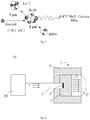
- the neutron capture therapy system 100 includes an accelerator 200 for generating a charged particle beam P, a neutron generator 10 for generating a neutron beam after being irradiated by the charged particle beam P, a beam shaping assembly 11, and a collimator 12.
- the beam shaping assembly 11 includes a moderator 13 and a reflector 14 surrounding the moderator 13.
- the neutron generator 10 generates a neutron beam N after being irradiated by the charged particle beam P, the moderator 13 decelerates the neutron beam N generated by the neutron generator 10 to a preset spectrum, and the reflector 14 leads the deflected neutrons back to increase the neutron intensity within a preset spectrum, and the collimator 12 concentrates the neutrons generated by the neutron generator for irradiation.
- the spectrum of the charged particle beam can be varied, the neutron capture therapy system 100 indirectly changes the spectrum of the neutron beam generated by the neutron generator by changing the spectrum of the charged particle beam.
- the spectrum changing of the charged particle beam P affects the spectrum of the neutron beam N. That is, the present disclosure indirectly changes the spectrum of the neutron beam N by changing the spectrum of the charged particle beam P so as to provide a better neutron depth dose distribution.
- the neutron capture therapy system 100 further includes a microwave generator 300 disposed at accelerator end.
- the microwave generator 300 is capable of generating microwaves of different frequencies, and the accelerator 200 accelerates the particle source in the accelerator according to different frequencies of the injected microwaves to change the spectrum of the charged particle beam output by the accelerator.
- the spectrum of the charged particle beam When the spectrum of the charged particle beam is low (which is named the first value), the spectrum of the neutron beam generated by the reaction of the charged particle with the neutron generator is low (the spectrum value of the first neutron beam); when the spectrum of the charged particle beam is high (which is named the second value), the spectrum of the neutron beam generated by the reaction of the charged particle with the neutron generator is high (the spectrum value of the second neutron beam), wherein the first value is lower than the second value, the spectrum value of the first neutron beam is lower than the spectrum value of the second neutron beam.
- the spectrum of the charged particle beam P is changed by changing the electric field intensity at the accelerator end. Since the electric field intensity at the accelerator end greatly affects the acceleration speed of the charged particle beam P, and the acceleration speed of the charged particle beam P directly affects the spectrum of the charged particle beam P, the spectrum of the neutron beam N generated by the charged particle beam P irradiates to the neutron generator 10 is affected.
- the present disclosure provides an electric field generating device 16 outside the vacuum tube 15 or outside the neutron generator 10 to generate an electric field capable of accelerating or decelerating the charged particle beam P before irradiating to the neutron generator 10.
- the electric field generating device 16 refers to an energized electrode.
- the electric field intensity difference is adjusted by controlling the voltage difference at the energized electrode to accelerate or decelerate the charged particle beam P, and the details will not be described herein.
- the purpose of providing such an electric field generating device 16 outside the vacuum tube 15 or outside the neutron generator 10 is to provide a second adjustment of the spectrum of the charged particle beam P accelerated by the accelerator 200, so as to obtain a neutron beam N with a spectrum level that is required in accordance with the neutron capture therapy when the charged particle beam P irradiates to the neutron generator 10. That is, the spectrum of the charged particle beam P is changed by changing the electric field at the accelerator end so as to indirectly change the spectrum of the neutron beam N.
- such an electric field generating device 16 may also be disposed outside the vacuum tube 15 and outside the neutron generator 10 respectively to adjust the spectrum of the charged particle beam P several times, thereby making it easier to achieve the spectrum adjustment, and finally obtaining the neutron beam N with a spectrum level required for the treatment.
- Fig. 5 is a third embodiment of the present disclosure for changing the spectrum of the charged particle beam P.
- a beam energy spectrum adjusting member 17 is located in the vacuum tube 15 and in front of the neutron generator 10, and the charged particle beam P irradiates to the beam energy spectrum adjusting member 17 to perform spectrum adjustment, and then irradiates to the neutron generator 10 to generate a neutron beam N, and finally achieves spectrum adjustment of the neutron beam N.
- the beam energy spectrum adjusting member 17 is disposed in the vacuum tube 15 and located below the neutron generator 10.
- the vacuum tube 15 is provided with an accommodating portion 151 under the neutron generator 10, and the beam energy spectrum adjusting member 17 is accommodated in the accommodating portion 151. Since different numbers of beam energy spectrum adjusting member 17 have different effects on the adjustment of the spectrum of the charged particle beam P, a plurality of beam energy spectrum adjusting members 17 are disposed in the vacuum tube 15, and the beam energy spectrum adjusting members 17 are respectively connected to a driving mechanism 18, and the driving mechanism 18 is able to control each of the beam energy spectrum adjusting member 17 to move upward or downward respectively, that is, the driving mechanism 18 can simultaneously move one or more of the beam energy spectrum adjusting member 17 upward or downward.
- the driving mechanism 18 is operated in accordance with the spectrum requirements of the neutron beam N, and the motion of each beam energy spectrum adjusting member 17 is controlled by the driving mechanism 18.
- the driving mechanism 18 controls the beam energy spectrum adjusting member 17 to move upward, the beam energy spectrum adjusting member 17 moves in front of the neutron generator 10, and the charged particle beam P irradiates to the beam energy spectrum adjusting member 17 to perform spectrum adjustment, and then the charged particle beam P irradiates to the neutron generator 10;
- the driving mechanism 18 controls the beam energy spectrum adjusting member 17 to move downward, the beam energy spectrum adjusting member 17 is accommodated in the accommodating portion 151, and the charged particle beam P directly irradiates to the neutron generator 10.
- the spectrum of the charged particle beam P is adjusted by the beam energy spectrum adjusting member 17, thereby indirectly adjusts the spectrum of the neutron beam N.
- the beam energy spectrum adjusting member may be disposed at other positions in the vacuum tube besides the position below the neutron generator, as long as it can be located in or not in front of the neutron generator when the spectrum of the charged particle beam needs or does not need to be adjusted.
- each beam energy spectrum adjusting member 17 is designed to have the same structure and each beam energy spectrum adjusting member 17 is sequentially arranged in the accommodating portion 151.
- the cross sections of the beam energy spectrum adjusting member 17 and the neutron generator 10 perpendicular to the irradiation direction of the charged particle beam P are circular, and the radius of the beam energy spectrum adjusting member 17 is smaller than that of the neutron generator 10.
- a cooling device (not shown) is provided on the outer periphery of the beam energy spectrum adjusting member 17.
- the arrangement of the cooling device of the beam energy spectrum adjusting member 17 can refer to the cooling method of the neutron generator 10 in the prior art, which will not be specifically described herein.
- the beam energy spectrum adjusting member 17 adjusts the spectrum of the charged particle beam P, and the cooling device cools the beam energy spectrum adjusting member 17.
- each of the beam energy spectrum adjusting members 17 may be the same or different.
- the materials of the beam energy spectrum adjusting members 17 may be the same or different.
- different requirements for the neutron beam N spectrum during neutron capture therapy can be achieved by controlling different numbers of the beam energy spectrum adjusting members 17 to move downward to be in front of the neutron generator 10.
- different requirements for the neutron beam N spectrum during neutron capture therapy can be achieved by controlling different numbers of beam energy spectrum adjusting members 17 to move downward, or by the controlling one or several of the beam energy spectrum adjusting members 17 made of different materials to move downward.
- the beam energy spectrum adjusting member 17 may be made of materials capable of generating a neutron beam N, such as lithium or beryllium. It should be noted that when the beam energy spectrum adjusting member 17 is made of a material capable of generating the neutron beam N, the beam energy spectrum adjusting member 17 should be placed as close as possible to the neutron generator 10, so that both the neutron beam generated by the irradiation of the charged particle beam P to the beam energy spectrum adjusting member 17 and the neutron beam generated by the irradiation of the charged particle beam P to the neutron generator are effectively utilized.
- the materials of the beam energy spectrum adjusting member 17 can not generate a neutron beam, it also can be used as long as the beam energy spectrum adjusting member 17 is disposed in the vacuum tube 15 and is able to move downward under the control of the driving mechanism 18 to be in front of the neutron generator 10, and realize the spectrum adjustment on the charged particle beam P irradiates to the neutron generator 10.
- the neutron generator 10 of the neutron capture therapy system 100 is connected to a power supply device 20.
- the neutron generator 10 is energized by the power supply device 20 to generate an electric field inside the neutron generator, and the beam spectrum of the charged particle beam P changes after the charged particle beam P irradiates to the neutron generator 10 being energized.
- a microwave generator in order to obtain a neutron beam N with better quality, it is also implementable to provide a microwave generator, an electric field generating device, a beam energy spectrum adjusting member, and a neutron generator connected to a power supply device simultaneously, so as to realize multiple spectrum adjustments on the charged particle beam P during the neutron capture therapy, and make it easier to obtain the neutron beam of the required spectrum level, which will not be specifically described herein.
Landscapes
- Engineering & Computer Science (AREA)
- Physics & Mathematics (AREA)
- Health & Medical Sciences (AREA)
- Biomedical Technology (AREA)
- Spectroscopy & Molecular Physics (AREA)
- High Energy & Nuclear Physics (AREA)
- Animal Behavior & Ethology (AREA)
- General Health & Medical Sciences (AREA)
- Veterinary Medicine (AREA)
- Public Health (AREA)
- Life Sciences & Earth Sciences (AREA)
- Pathology (AREA)
- Nuclear Medicine, Radiotherapy & Molecular Imaging (AREA)
- Radiology & Medical Imaging (AREA)
- General Engineering & Computer Science (AREA)
- Plasma & Fusion (AREA)
- Chemical Kinetics & Catalysis (AREA)
- Chemical & Material Sciences (AREA)
- General Chemical & Material Sciences (AREA)
- Optics & Photonics (AREA)
- Radiation-Therapy Devices (AREA)
- Particle Accelerators (AREA)
Abstract
Description
- The present disclosure relates generally to a radioactive ray irradiation therapy system, and, more particularly, to a neutron capture therapy system.
- As atomics moves ahead, such radiotherapy as Cobalt-60, linear accelerators and electron beams has been one of major means to cancer therapy. However, conventional photon or electron therapy has been undergone physical restrictions of radioactive rays; for example, many normal tissues on a beam path will be damaged as tumor cells are destroyed. On the other hand, sensitivity of tumor cells to the radioactive rays differs greatly, so in most cases, conventional radiotherapy falls short of treatment effectiveness on radio resistant malignant tumors (such as glioblastoma multiforme and melanoma).
- For the purpose of reducing radiation damage to the normal tissue surrounding a tumor site, target therapy in chemotherapy has been employed in the radiotherapy. While for high-radio resistant tumor cells, radiation sources with high RBE (relative biological effectiveness) including such as proton, heavy particle and neutron capture therapy have also developed. Among them, the neutron capture therapy combines the target therapy with the RBE, such as the boron neutron capture therapy (BNCT). By virtue of specific grouping of boronated pharmaceuticals in the tumor cells and precise neutron beam regulation, BNCT is provided as a better cancer therapy choice than conventional radiotherapy.
- BNCT takes advantage that the boron (10B)-containing pharmaceuticals have high neutron capture cross section and produces 4He and 7Li heavy charged particles through 10B(n,α)7Li neutron capture and nuclear fission reaction. As illustrated in
FIG. 1 , a schematic view of boron neutron capture reaction are shown, the two charged particles, with average energy at about 2.33MeV, are of linear energy transfer (LET) and short-range characteristics. LET and range of the alpha particle are 150keV/micrometer and 8 micrometers respectively while those of the heavy charged particle 7Li are 175keV/micrometer and 5 micrometers respectively, and the total range of the two particles approximately amounts to a cell size. Therefore, radiation damage to living organisms may be restricted at the cells' level. When the boronated pharmaceuticals are gathered in the tumor cells selectively, only the tumor cells will be destroyed locally with a proper neutron source on the premise of having no major normal tissue damage. - BNCT is also well known for binary cancer therapy, for its effectiveness depending on the concentration of the boronated pharmaceuticals and the number of the thermal neutrons at the tumor site. Thus, besides development of the boronated pharmaceuticals, improvement of quality of the neutron source also plays a significant role in BNCT researches.
- In order to obtain neutron beams with various spectrums during neutron capture therapy to meet the requirements for the neutron beam energy spectrum during actual treatments, an aspect of the present disclosure provides a neutron capture therapy system, the neutron capture therapy system includes an accelerator, the accelerator generates a charged particle beam; a neutron generator, the neutron generator generates a neutron beam after being irradiated by charged particle beam; a vacuum tube, the vacuum tube transports the charged particles accelerated by the accelerator to the neutron generator; a beam shaping assembly, the beam shaping assembly includes a moderator and a reflector surrounding the moderator, the moderator moderates the neutrons generated by the neutron generator to a preset spectrum, and the reflector leads the deflected neutrons back to increase the neutron intensity within the preset spectrum; and a collimator, the collimator concentrates the neutrons generated by the neutron generator; the spectrum of the neutron beam is changed by changing the spectrum of the charged particle beam. The spectrum of the neutron beam indirectly changes by changing the spectrum of charged particle beam irradiates to the neutron generator primarily, thereby the depth dose distribution is changed.
- Further, in order to achieve different spectrum of charged particle beam, a microwave generator is used to provide different pulses to accelerate the particles source in the accelerator. The neutron capture therapy system includes a microwave generator capable of injecting microwaves into the accelerator, the spectrum of the charged particle beam output by the accelerator changes according to the microwaves injected at different frequencies, when the spectrum of the charged particle beam is at a first value, the charged particles react with the neutron generator and generates a spectrum of neutron beam at a first value, and when the spectrum of the charged particle beam is at a second value, the charged particles react with the neutron generator and generates a spectrum of neutron beam at a second value, wherein the spectrum of the first value of the charged particle beam is lower than that of the second value, and the spectrum of the first value of the neutron beam is lower than that of the second value.
- Further, the spectrum of the charged particle beam changes as the changing of electric field intensity of the accelerator (at the accelerator end). The structures before the charged particles and the neutron generator undergo a nuclear reaction are understood to be the accelerator end.
- More particularly, an electric field generating device is provided outside the vacuum tube and/or the neutron generator, the electric field generating device is capable of generating an electric field so as to accelerate or decelerate the charged particle beam before the charged particle beam irradiates to the neutron generator. The electric field generating device refers to devices capable of generating an electric field on the outer periphery of the vacuum tube or the neutron generator and capable of accelerating or decelerating the charged particles by the electric field before being irradiated to the neutron generator, for example, an energized electrode.
- Further, the neutron capture therapy system further includes a beam energy spectrum adjusting member capable of adjusting the spectrum of the charged particle beam, when the beam energy spectrum adjusting member is located in the vacuum tube and is in front of the neutron generator, the spectrum of the charged particle beam is adjusted after irradiating to the beam energy spectrum adjusting member, and the charged particle beam then irradiates to the neutron generator to generate the neutron beam.
- Further, the vacuum tube is provided with an accommodating portion, the beam energy spectrum adjusting member is accommodated in the accommodating portion and is connected with a driving mechanism capable of moving the beam energy spectrum adjusting member, when the driving mechanism controls the beam energy spectrum adjusting member to move to the front of the neutron generator, the spectrum of the charged particles changes after irradiating to the beam energy spectrum adjusting member and then irradiates to the neutron generator; when the driving mechanism controls the beam energy spectrum adjusting member to be accommodated in the accommodating portion but not in front of the neutron generator, the charged particle beam directly irradiates to the neutron generator.
- More particularly, the neutron capture therapy system includes a plurality of the beam energy spectrum adjusting members, and different numbers of the beam energy spectrum adjusting members have different spectrum adjustment effects on the charged particle beam, the driving mechanism drives each beam energy spectrum adjusting member to move up or down separately to adjust the spectrum of the charged particle beam. The neutron energy spectrum adjusting member may be made of materials capable of generating neutrons, such as beryllium or lithium.
- Each beam energy spectrum adjusting member is made of different materials, and the beam energy spectrum adjusting member made of different materials has different spectrum adjustment effects on the charged particle beam.
- Further, the neutron generator is connected to a power supply device and energized by the power supply device, and the beam spectrum of the charged particle beam changes after the charged particles irradiates to the energized neutron generator.
- Compared to the prior art, the neutron capture therapy system of the present disclosure indirectly changes the spectrum of the neutron beam by adjusting the spectrum of the charged particle beam to meet different requirements for the spectrum of the neutron beam under different treatment conditions, and has a simple structure and is easy to implement.
-
-
FIG. 1 is a schematic view of a boron neutron capture reaction. -
FIG. 2 is a schematic view of a neutron capture therapy system of the present disclosure. -
FIG. 3 is schematic view of a neutron capture therapy system provided with a microwave generator. -
FIG. 4 is a schematic view of a neutron capture therapy system provided with an electric field generating device. -
FIG. 5 is a schematic view of a neutron capture therapy system provided with beam energy spectrum adjusting members. -
FIG.6 is a schematic view showing energization of a plating layer of a neutron generator. - Neutron capture therapy (NCT) has been increasingly practiced as an effective cancer curing means in recent years, and BNCT is the most common. Neutrons for NCT may be supplied by nuclear reactors or accelerators. Take AB-BNCT for example, its principal components include, in general, an accelerator for accelerating charged particles (such as protons and deuterons), a target, a heat removal system and a beam shaping assembly. The accelerated charged particles interact with the metal target to produce the neutrons, and suitable nuclear reactions are always determined according to such characteristics as desired neutron yield and energy, available accelerated charged particle energy and current and materialization of the metal target, among which the most discussed two are 7Li (p, n) 7Be and 9Be (p, n) 9B and both are endothermic reaction. Their energy thresholds are 1.881MeV and 2.055MeV respectively. Epithermal neutrons at a keV energy level are considered ideal neutron sources for BNCT. Theoretically, bombardment with lithium target using protons with energy slightly higher than the thresholds may produce neutrons relatively low in energy, so the neutrons may be used clinically without many moderations. However, Li (lithium) and Be (beryllium) and protons of threshold energy exhibit not high action cross section. In order to produce sufficient neutron fluxes, high-energy protons are usually selected to trigger the nuclear reactions.
- No matter BNCT neutron sources are from the nuclear reactor or the nuclear reactions between the accelerator charged particles and the target, only mixed radiation fields are produced, that is, beams comprise neutrons and photons having energies from low to high. As for BNCT in the depth of tumors, except the epithermal neutrons, the more the residual quantity of radiation ray is, the higher the proportion of nonselective dose deposition in the normal tissue is. Therefore, radiation causing unnecessary dose should be lowered down as much as possible. Besides air beam quality factors, dose is calculated using a human head tissue prosthesis in order to understand dose distribution of the neutrons in the human body. The prosthesis beam quality factors are later used as design reference to the neutron beams, which is elaborated hereinafter.
- The International Atomic Energy Agency (IAEA) has given five suggestions on the air beam quality factors for the clinical BNCT neutron sources. The suggestions may be used for differentiating the neutron sources and as reference for selecting neutron production pathways and designing the beam shaping assembly, and are shown as follows:
- Epithermal neutron flux > 1 x 10⁹ n/cm2s
- Fast neutron contamination < 2 x 10-13 Gy-cm2/n
- Photon contamination < 2 x 10-13 Gy-cm2/n
- Thermal to epithermal neutron flux ratio < 0.05
- Epithermal neutron current to flux ratio > 0.7
- Note: the epithermal neutron energy range is between 0.5eV and 40keV, the thermal neutron energy range is lower than 0.5eV, and the fast neutron energy range is higher than 40keV.
- The epithermal neutron flux and the concentration of the boronated pharmaceuticals at the tumor site codetermine clinical therapy time. If the boronated pharmaceuticals at the tumor site are high enough in concentration, the epithermal neutron flux may be reduced. On the contrary, if the concentration of the boronated pharmaceuticals in the tumors is at a low level, it is required that the epithermal neutrons in the high epithermal neutron flux should provide enough doses to the tumors. The given standard on the epithermal neutron flux from IAEA is more than 109 epithermal neutrons per square centimeter per second. In this flux of neutron beams, therapy time may be approximately controlled shorter than an hour with the boronated pharmaceuticals. Thus, except that patients are well positioned and feel more comfortable in shorter therapy time, and limited residence time of the boronated pharmaceuticals in the tumors may be effectively utilized.
- Unnecessary dose on the normal tissue produced by fast neutrons are considered as contamination. The dose exhibit positive correlation to neutron energy, hence, the quantity of the fast neutrons in the neutron beams should be reduced to the greatest extent. Dose of the fast neutrons per unit epithermal neutron flux is defined as the fast neutron contamination, and according to IAEA, it is supposed to be less than 2*10-13Gy-cm2/n.
- Gamma-ray long-range penetration radiation will selectively result in dose deposit of all tissues in beam paths, so that lowering the quantity of gamma-ray is also the exclusive requirement in neutron beam design. Gamma-ray dose accompanied per unit epithermal neutron flux is defined as gamma-ray contamination which is suggested being less than 2*10-13Gy-cm2/n according to IAEA.
- The thermal neutrons are so fast in rate of decay and poor in penetration that they leave most of energy in skin tissue after entering the body. Except for skin tumors like melanocytoma, the thermal neutrons serve as neutron sources of BNCT, in other cases like brain tumors, the quantity of the thermal neutrons has to be lowered. The thermal to epithermal neutron flux ratio is recommended at lower than 0.05 in accordance with IAEA.
- The epithermal neutron current to flux ratio stands for beam direction, the higher the ratio is, the better the forward direction of the neutron beams is, and the neutron beams in the better forward direction may reduce dose surrounding the normal tissue resulted from neutron scattering. In addition, treatable depth as well as positioning posture is improved. The epithermal neutron current to flux ratio is better of larger than 0.7 according to IAEA.
- The prosthesis beam quality factors are deduced by virtue of the dose distribution in the tissue obtained by the prosthesis according to a dose-depth curve of the normal tissue and the tumors. The three parameters as follows may be used for comparing different neutron beam therapy effects.
- Tumor dose is equal to the depth of the maximum dose of the normal tissue. Dose of the tumor cells at a position behind the depth is less than the maximum dose of the normal tissue, that is, boron neutron capture loses its advantages. The advantage depth indicates penetrability of neutron beams. Calculated in cm, the larger the advantage depth is, the larger the treatable tumor depth is.
- The advantage depth dose rate is the tumor dose rate of the advantage depth and also equal to the maximum dose rate of the normal tissue. It may have effects on length of the therapy time as the total dose on the normal tissue is a factor capable of influencing the total dose given to the tumors. The higher it is, the shorter the irradiation time for giving a certain dose on the tumors is, calculated by cGy/mA-min.
- The average dose ratio received by the tumors and the normal tissue from the brain surface to the advantage depth is called as advantage ratio. The average ratio may be calculated using dose-depth curvilinear integral. The higher the advantage ratio is, the better the therapy effect of the neutron beams is.
- To provide comparison reference to design of the beam shaping assembly, we also provide the following parameters for evaluating expression advantages and disadvantages of the neutron beams in the embodiments of the present disclosure except the air beam quality factors of IAEA and the abovementioned parameters.
- 1. Irradiation time <=30min (proton current for accelerator is 10mA)
- 2. 30.0RBE-Gy treatable depth >=7cm
- 3. The maximum tumor dose>=60.0RBE-Gy
- 4. The maximum dose of normal brain tissue<=12.5RBE-Gy
- 5. The maximum skin dose<=11.0RBE-Gy
- Note: RBE stands for relative biological effectiveness. Since photons and neutrons express different biological effectiveness, the dose above should be multiplied with RBE of different tissues to obtain equivalent dose.
- In actual neutron capture therapy process, different patients and tumors often require different energies of neutrons, and how to get an appropriate spectrum of the neutron beam for treatment according to the specific situation is to be solved. Before the charged particle beam irradiates to the neutron generator, change its spectrum, so as to provide multiple spectrums of neutron beam. Since the spectrum of the charged particle beam is changed and the neutron beam is generated by the irradiation of the charged particle beam to neutron generator, the spectrum changing of the charged particle beam directly affects the spectrum of the neutron beam. The spectrum of the neutron beam is changed by changing the spectrum of the charged particle beam according to the present disclosure which includes but not limits to boron neutron capture therapy, and the neutron capture therapy system of the present disclosure is specifically described below.
- As shown in
FIG. 2 , the present disclosure provides a neutroncapture therapy system 100. The neutroncapture therapy system 100 includes anaccelerator 200 for generating a charged particle beam P, aneutron generator 10 for generating a neutron beam after being irradiated by the charged particle beam P, abeam shaping assembly 11, and acollimator 12. Thebeam shaping assembly 11 includes amoderator 13 and areflector 14 surrounding themoderator 13. Theneutron generator 10 generates a neutron beam N after being irradiated by the charged particle beam P, themoderator 13 decelerates the neutron beam N generated by theneutron generator 10 to a preset spectrum, and thereflector 14 leads the deflected neutrons back to increase the neutron intensity within a preset spectrum, and thecollimator 12 concentrates the neutrons generated by the neutron generator for irradiation. The spectrum of the charged particle beam can be varied, the neutroncapture therapy system 100 indirectly changes the spectrum of the neutron beam generated by the neutron generator by changing the spectrum of the charged particle beam. Since the neutron beam N is generated by irradiating theneutron generator 10 with the charged particle beam P, the spectrum changing of the charged particle beam P affects the spectrum of the neutron beam N. That is, the present disclosure indirectly changes the spectrum of the neutron beam N by changing the spectrum of the charged particle beam P so as to provide a better neutron depth dose distribution. - As a first embodiment, as shown in
FIG. 3 , the neutroncapture therapy system 100 further includes amicrowave generator 300 disposed at accelerator end. Themicrowave generator 300 is capable of generating microwaves of different frequencies, and theaccelerator 200 accelerates the particle source in the accelerator according to different frequencies of the injected microwaves to change the spectrum of the charged particle beam output by the accelerator. The higher the frequency of the microwave of themicrowave generator 300 injected into theaccelerator 200 is, the faster theaccelerator 200 accelerates the particle source, and the higher the spectrum of the charged particle beam P is, the higher the spectrum of the neutron beam N generated by theneutron generator 10 after being irradiated by the charged particle beam P is; the lower the frequency of the microwave of themicrowave generator 300 injected into theaccelerator 200 is, the slower theaccelerator 200 accelerates the particle source, and the lower the spectrum of the charged particle beam P is, the lower the spectrum of the neutron beam N generated by theneutron generator 10 after being irradiated by the charged particle beam P is. When the spectrum of the charged particle beam is low (which is named the first value), the spectrum of the neutron beam generated by the reaction of the charged particle with the neutron generator is low (the spectrum value of the first neutron beam); when the spectrum of the charged particle beam is high (which is named the second value), the spectrum of the neutron beam generated by the reaction of the charged particle with the neutron generator is high (the spectrum value of the second neutron beam), wherein the first value is lower than the second value, the spectrum value of the first neutron beam is lower than the spectrum value of the second neutron beam. - As shown in
FIG. 4 , as a second embodiment, the spectrum of the charged particle beam P is changed by changing the electric field intensity at the accelerator end. Since the electric field intensity at the accelerator end greatly affects the acceleration speed of the charged particle beam P, and the acceleration speed of the charged particle beam P directly affects the spectrum of the charged particle beam P, the spectrum of the neutron beam N generated by the charged particle beam P irradiates to theneutron generator 10 is affected. - As a specific embodiment for changing the electric field intensity at the accelerator end, the present disclosure provides an electric
field generating device 16 outside thevacuum tube 15 or outside theneutron generator 10 to generate an electric field capable of accelerating or decelerating the charged particle beam P before irradiating to theneutron generator 10. Preferably, the electricfield generating device 16 refers to an energized electrode. The electric field intensity difference is adjusted by controlling the voltage difference at the energized electrode to accelerate or decelerate the charged particle beam P, and the details will not be described herein. - Actually, the purpose of providing such an electric
field generating device 16 outside thevacuum tube 15 or outside theneutron generator 10 is to provide a second adjustment of the spectrum of the charged particle beam P accelerated by theaccelerator 200, so as to obtain a neutron beam N with a spectrum level that is required in accordance with the neutron capture therapy when the charged particle beam P irradiates to theneutron generator 10. That is, the spectrum of the charged particle beam P is changed by changing the electric field at the accelerator end so as to indirectly change the spectrum of the neutron beam N. Certainly, such an electricfield generating device 16 may also be disposed outside thevacuum tube 15 and outside theneutron generator 10 respectively to adjust the spectrum of the charged particle beam P several times, thereby making it easier to achieve the spectrum adjustment, and finally obtaining the neutron beam N with a spectrum level required for the treatment. -
Fig. 5 is a third embodiment of the present disclosure for changing the spectrum of the charged particle beam P. In the present embodiment, a beam energyspectrum adjusting member 17 is located in thevacuum tube 15 and in front of theneutron generator 10, and the charged particle beam P irradiates to the beam energyspectrum adjusting member 17 to perform spectrum adjustment, and then irradiates to theneutron generator 10 to generate a neutron beam N, and finally achieves spectrum adjustment of the neutron beam N. - The beam energy
spectrum adjusting member 17 is disposed in thevacuum tube 15 and located below theneutron generator 10. Thevacuum tube 15 is provided with anaccommodating portion 151 under theneutron generator 10, and the beam energyspectrum adjusting member 17 is accommodated in theaccommodating portion 151. Since different numbers of beam energyspectrum adjusting member 17 have different effects on the adjustment of the spectrum of the charged particle beam P, a plurality of beam energyspectrum adjusting members 17 are disposed in thevacuum tube 15, and the beam energyspectrum adjusting members 17 are respectively connected to adriving mechanism 18, and thedriving mechanism 18 is able to control each of the beam energyspectrum adjusting member 17 to move upward or downward respectively, that is, thedriving mechanism 18 can simultaneously move one or more of the beam energyspectrum adjusting member 17 upward or downward. During actual neutron capture therapy, thedriving mechanism 18 is operated in accordance with the spectrum requirements of the neutron beam N, and the motion of each beam energyspectrum adjusting member 17 is controlled by thedriving mechanism 18. When thedriving mechanism 18 controls the beam energyspectrum adjusting member 17 to move upward, the beam energyspectrum adjusting member 17 moves in front of theneutron generator 10, and the charged particle beam P irradiates to the beam energyspectrum adjusting member 17 to perform spectrum adjustment, and then the charged particle beam P irradiates to theneutron generator 10; when thedriving mechanism 18 controls the beam energyspectrum adjusting member 17 to move downward, the beam energyspectrum adjusting member 17 is accommodated in theaccommodating portion 151, and the charged particle beam P directly irradiates to theneutron generator 10. The spectrum of the charged particle beam P is adjusted by the beam energyspectrum adjusting member 17, thereby indirectly adjusts the spectrum of the neutron beam N. Furthermore, the beam energy spectrum adjusting member may be disposed at other positions in the vacuum tube besides the position below the neutron generator, as long as it can be located in or not in front of the neutron generator when the spectrum of the charged particle beam needs or does not need to be adjusted. - In order to facilitate the manufacture and installation of the beam energy
spectrum adjusting member 17, each beam energyspectrum adjusting member 17 is designed to have the same structure and each beam energyspectrum adjusting member 17 is sequentially arranged in theaccommodating portion 151. The cross sections of the beam energyspectrum adjusting member 17 and theneutron generator 10 perpendicular to the irradiation direction of the charged particle beam P are circular, and the radius of the beam energyspectrum adjusting member 17 is smaller than that of theneutron generator 10. In order to alleviate the heat of the beam energyspectrum adjusting member 17 after being irradiated by the charged particle beam P, a cooling device (not shown) is provided on the outer periphery of the beam energyspectrum adjusting member 17. The arrangement of the cooling device of the beam energyspectrum adjusting member 17 can refer to the cooling method of theneutron generator 10 in the prior art, which will not be specifically described herein. When the charged particle beam P irradiates to the beam energyspectrum adjusting member 17, the beam energyspectrum adjusting member 17 adjusts the spectrum of the charged particle beam P, and the cooling device cools the beam energyspectrum adjusting member 17. - The thickness of each of the beam energy
spectrum adjusting members 17 may be the same or different. In addition, the materials of the beam energyspectrum adjusting members 17 may be the same or different. When all the beam energyspectrum adjusting members 17 are made of the same materials, different requirements for the neutron beam N spectrum during neutron capture therapy can be achieved by controlling different numbers of the beam energyspectrum adjusting members 17 to move downward to be in front of theneutron generator 10. When the beam energyspectrum adjusting member 17 is made of different materials, different requirements for the neutron beam N spectrum during neutron capture therapy can be achieved by controlling different numbers of beam energyspectrum adjusting members 17 to move downward, or by the controlling one or several of the beam energyspectrum adjusting members 17 made of different materials to move downward. Alternatively, the beam energyspectrum adjusting member 17 may be made of materials capable of generating a neutron beam N, such as lithium or beryllium. It should be noted that when the beam energyspectrum adjusting member 17 is made of a material capable of generating the neutron beam N, the beam energyspectrum adjusting member 17 should be placed as close as possible to theneutron generator 10, so that both the neutron beam generated by the irradiation of the charged particle beam P to the beam energyspectrum adjusting member 17 and the neutron beam generated by the irradiation of the charged particle beam P to the neutron generator are effectively utilized. Certainly, even the materials of the beam energyspectrum adjusting member 17 can not generate a neutron beam, it also can be used as long as the beam energyspectrum adjusting member 17 is disposed in thevacuum tube 15 and is able to move downward under the control of thedriving mechanism 18 to be in front of theneutron generator 10, and realize the spectrum adjustment on the charged particle beam P irradiates to theneutron generator 10. - Referring to
FIG. 6 , as a fourth embodiment, theneutron generator 10 of the neutroncapture therapy system 100 is connected to apower supply device 20. Theneutron generator 10 is energized by thepower supply device 20 to generate an electric field inside the neutron generator, and the beam spectrum of the charged particle beam P changes after the charged particle beam P irradiates to theneutron generator 10 being energized. - Certainly, in order to obtain a neutron beam N with better quality, it is also implementable to provide a microwave generator, an electric field generating device, a beam energy spectrum adjusting member, and a neutron generator connected to a power supply device simultaneously, so as to realize multiple spectrum adjustments on the charged particle beam P during the neutron capture therapy, and make it easier to obtain the neutron beam of the required spectrum level, which will not be specifically described herein.
- The above illustrates and describes basic principles, main features and advantages of the present disclosure. Those skilled in the art should appreciate that the above embodiments do not limit the present disclosure in any form. Technical solutions obtained by equivalent substitution or equivalent variations all fall within the scope of the present disclosure.
Claims (10)
- A neutron capture therapy system comprising:an accelerator, wherein the accelerator generates a charged particle beam;a neutron generator, wherein the neutron generator generates a neutron beam after being irradiated by the charged particle beam;a vacuum tube, wherein the vacuum tube transports charged particles accelerated by the accelerator to the neutron generator;a beam shaping assembly, wherein the beam shaping assembly comprises a moderator and a reflector surrounding the moderator, the moderator moderates the neutrons generated by the neutron generator to a preset spectrum, and the reflector leads the deflected neutrons back to increase the neutron intensity within the preset spectrum; anda collimator, wherein the collimator concentrates the neutrons generated by the neutron generator,wherein the spectrum of the neutron beam is changed by changing the spectrum of the charged particle beam.
- The neutron capture therapy system according to Claim 1, wherein the neutron capture therapy system further comprises a microwave generator capable of injecting microwaves into the accelerator, the spectrum of the charged particle beam output by the accelerator changes according to the injected microwaves at different frequencies, when the spectrum of the charged particle beam is at a first value, the charged particles react with the neutron generator and generates a spectrum of neutron beam at a first value, and when the spectrum of the charged particle beam is at a second value, the charged particles react with the neutron generator and generates a spectrum of neutron beam at a second value, wherein the spectrum of the first value of the charged particle beam is lower than that of the second value, and the spectrum of the first value of the neutron beam is lower than that of the second value.
- The neutron capture therapy system according to Claim 1, wherein the spectrum of the charged particle beam changes as the changing of electric field intensity of the accelerator.
- The neutron capture therapy system according to Claim 3, wherein an electric field generating device is provided outside the vacuum tube and/or the neutron generator, the electric field generating device is capable of generating an electric field so as to accelerate or decelerate the charged particle beam before the charged particle beam irradiates to the neutron generator.
- The neutron capture therapy system according to Claim 1, wherein the neutron capture therapy system further comprises a beam energy spectrum adjusting member capable of adjusting spectrum of the charged particle beam, when the beam energy spectrum adjusting member is located in the vacuum tube and is in front of the neutron generator, the spectrum of the charged particle beam is adjusted after irradiating to the beam energy spectrum adjusting member, and then the charged particle beam irradiates to the neutron generator to generate the neutron beam.
- The neutron capture therapy system according to Claim 5, wherein the vacuum tube is provided with an accommodating portion, the beam energy spectrum adjusting member is accommodated in the accommodating portion and is connected with a driving mechanism capable of moving the beam energy spectrum adjusting member, when the driving mechanism controls the beam energy spectrum adjusting member to move to the front of the neutron generator, the spectrum of the charged particle beam changes after irradiating to the beam energy spectrum adjusting member and then irradiates to the neutron generator; when the driving mechanism controls the beam energy spectrum adjusting member to be accommodated in the accommodating portion and not in front of the neutron generator, the charged particle beam directly irradiates to the neutron generator.
- The neutron capture therapy system according to Claim 6, wherein the neutron capture therapy system comprises a plurality of the beam energy spectrum adjusting members, and different numbers of the beam energy spectrum adjusting members have different spectrum adjustment effects on the charged particle beam, the driving mechanism drives each beam energy spectrum adjusting member to move separately to adjust the spectrum of the charged particle beam.
- The neutron capture therapy system according to Claim 6, wherein each beam energy spectrum adjusting member is made of different materials, and the beam energy spectrum adjusting members made of different materials have different spectrum adjustment effects on the charged particle beam.
- The neutron capture therapy system according to Claim 1, wherein the neutron generator is connected to a power supply device and energized by the power supply device, and the beam spectrum of the charged particle beam changes after the charged particle beam irradiates to the energized neutron generator.
- The neutron capture therapy system according to Claim 1, wherein the neutron capture therapy system indirectly changes the spectrum of the neutron beam by changing the beam spectrum of the charged particle beam, and then changes the neutron depth dose distribution.
Applications Claiming Priority (3)
| Application Number | Priority Date | Filing Date | Title |
|---|---|---|---|
| CN201610930008.7A CN107998517B (en) | 2016-10-31 | 2016-10-31 | Neutron capture therapy system |
| CN201621154870.5U CN206535011U (en) | 2016-10-31 | 2016-10-31 | Neutron capture treatment system |
| PCT/CN2017/092702 WO2018076790A1 (en) | 2016-10-31 | 2017-07-13 | Neutron capture therapy system |
Publications (3)
| Publication Number | Publication Date |
|---|---|
| EP3517172A1 true EP3517172A1 (en) | 2019-07-31 |
| EP3517172A4 EP3517172A4 (en) | 2019-10-09 |
| EP3517172B1 EP3517172B1 (en) | 2021-04-14 |
Family
ID=62023195
Family Applications (1)
| Application Number | Title | Priority Date | Filing Date |
|---|---|---|---|
| EP17864029.8A Active EP3517172B1 (en) | 2016-10-31 | 2017-07-13 | Neutron capture therapy system |
Country Status (5)
| Country | Link |
|---|---|
| US (1) | US10773104B2 (en) |
| EP (1) | EP3517172B1 (en) |
| JP (1) | JP6831921B2 (en) |
| TW (1) | TWI632932B (en) |
| WO (1) | WO2018076790A1 (en) |
Families Citing this family (10)
| Publication number | Priority date | Publication date | Assignee | Title |
|---|---|---|---|---|
| WO2016179381A1 (en) | 2015-05-06 | 2016-11-10 | Neutron Therapeuutics Inc. | Neutron target for boron neutron capture therapy |
| JP6831921B2 (en) * | 2016-10-31 | 2021-02-17 | 南京中硼▲聯▼康医▲療▼科技有限公司Neuboron Medtech Ltd. | Neutron capture therapy system |
| US10462893B2 (en) | 2017-06-05 | 2019-10-29 | Neutron Therapeutics, Inc. | Method and system for surface modification of substrate for ion beam target |
| RU2743972C1 (en) * | 2017-08-24 | 2021-03-01 | Нойборон Медтех Лтд. | Neutron capture therapy system |
| CN109496051A (en) * | 2018-12-21 | 2019-03-19 | 北京中百源国际科技创新研究有限公司 | It is a kind of for increasing the slowing down device of low number of neutrons |
| CN111821580A (en) * | 2019-04-17 | 2020-10-27 | 中硼(厦门)医疗器械有限公司 | Neutron capture therapy system and beam shaper for neutron capture therapy system |
| US11517769B2 (en) * | 2019-07-10 | 2022-12-06 | Ricoh Company, Ltd. | Neutron beam transmission adjusting device comprising a neutron beam transmission unit including a neutron reactant, method for producing neutron beam transmission adjusting device, and neutron beam adjusting method |
| EP4183448A4 (en) * | 2020-07-20 | 2024-05-22 | Neuboron Therapy System Ltd. | Radiotherapy system and safety interlock control method therefor |
| CN114522353A (en) * | 2020-11-23 | 2022-05-24 | 南京中硼联康医疗科技有限公司 | Animal irradiation system and irradiation fixing device thereof |
| JP2022150626A (en) * | 2021-03-26 | 2022-10-07 | 住友重機械工業株式会社 | Treatment preparation device and treatment facility |
Family Cites Families (31)
| Publication number | Priority date | Publication date | Assignee | Title |
|---|---|---|---|---|
| US4252607A (en) * | 1979-02-05 | 1981-02-24 | The United States Of America As Represented By The United States Department Of Energy | Radiation source |
| FR2679727B1 (en) * | 1991-07-23 | 1997-01-03 | Cgr Mev | PROTON ACCELERATOR USING MAGNETICALLY COUPLED PROGRESSIVE WAVE. |
| JP2006047115A (en) * | 2004-08-04 | 2006-02-16 | Mitsubishi Heavy Ind Ltd | Neutron generating apparatus, target and neutron irradiation system |
| DE102007020599A1 (en) * | 2007-05-02 | 2008-11-06 | Siemens Ag | Particle therapy system |
| WO2009108906A1 (en) * | 2008-02-27 | 2009-09-03 | Starfire Industries Llc | Method and system for in situ depositon and regeneration of high efficiency target materials for long life nuclear reaction devices |
| DE102009032275A1 (en) * | 2009-07-08 | 2011-01-13 | Siemens Aktiengesellschaft | Accelerator system and method for adjusting a particle energy |
| US8269197B2 (en) * | 2009-07-22 | 2012-09-18 | Intraop Medical Corporation | Method and system for electron beam applications |
| CN102194635A (en) * | 2010-03-18 | 2011-09-21 | 上海凯世通半导体有限公司 | Ion implanting system and method |
| JP5619462B2 (en) * | 2010-04-02 | 2014-11-05 | 三菱電機株式会社 | Treatment planning device and particle beam treatment device using treatment plan of treatment planning device |
| EP2400506A1 (en) * | 2010-06-23 | 2011-12-28 | GSI Helmholtzzentrum für Schwerionenforschung GmbH | Particle beam generating device |
| JP5645159B2 (en) * | 2010-10-08 | 2014-12-24 | 独立行政法人放射線医学総合研究所 | Beam measuring apparatus, measuring method therefor, and beam transport system |
| US8541756B1 (en) * | 2012-05-08 | 2013-09-24 | Accuray Incorporated | Systems and methods for generating X-rays and neutrons using a single linear accelerator |
| JP6113453B2 (en) * | 2012-07-13 | 2017-04-12 | 株式会社八神製作所 | Target for neutron generator and manufacturing method thereof |
| EP3043863B1 (en) * | 2013-09-11 | 2019-12-04 | The Board of Trustees of the Leland Stanford Junior University | Arrays of accelerating structures and rapid imaging for facilitating rapid radiation therapies |
| CN104470193B (en) * | 2013-09-22 | 2017-07-25 | 同方威视技术股份有限公司 | Control the method and its system of standing wave accelerator |
| JP6257994B2 (en) * | 2013-10-22 | 2018-01-10 | 株式会社東芝 | Neutron generator and medical accelerator system |
| JP6692115B2 (en) * | 2014-02-25 | 2020-05-13 | 株式会社日立製作所 | Beam position monitoring device and charged particle beam irradiation system |
| DK3032927T3 (en) * | 2014-12-08 | 2017-02-06 | Neuboron Medtech Ltd | RADIATING DEVICE FOR NEUTRON COLLECTION THERAPY |
| JP6565113B2 (en) * | 2015-03-05 | 2019-08-28 | 住友重機械工業株式会社 | Neutron capture therapy device |
| CN205073541U (en) * | 2015-09-28 | 2016-03-09 | 南京中硼联康医疗科技有限公司 | A beam diagnostic system for neutron capture treatment system |
| CN205460520U (en) * | 2016-01-08 | 2016-08-17 | 南京中硼联康医疗科技有限公司 | Beam shaper for neutron -capture therapy |
| RU2720707C2 (en) * | 2016-01-08 | 2020-05-12 | Неуборон Медтек Лтд. | Beam forming element intended for use in neutron capture therapy |
| EP3424561B1 (en) * | 2016-03-25 | 2019-10-09 | Neuboron Medtech Ltd. | Boron neutron capture treating system and alpha-amino acid-like boron trifluoride compounds for use in treating tumors |
| CN108778420A (en) * | 2016-03-31 | 2018-11-09 | 住友重机械工业株式会社 | Neutron capture cure treatment planning systems |
| JP6754847B2 (en) * | 2016-07-04 | 2020-09-16 | 南京中硼▲聯▼康医▲療▼科技有限公司Neuboron Medtech Ltd. | Neutron therapy device |
| WO2018006550A1 (en) * | 2016-07-04 | 2018-01-11 | 南京中硼联康医疗科技有限公司 | Neutron therapy device |
| JP6831921B2 (en) * | 2016-10-31 | 2021-02-17 | 南京中硼▲聯▼康医▲療▼科技有限公司Neuboron Medtech Ltd. | Neutron capture therapy system |
| TWI614042B (en) * | 2016-12-02 | 2018-02-11 | 財團法人工業技術研究院 | Neutron beam source generator and filter |
| JP6742259B2 (en) * | 2017-03-02 | 2020-08-19 | 住友重機械工業株式会社 | Neutron beam detection system and method for setting neutron beam detection system |
| WO2018176686A1 (en) * | 2017-03-29 | 2018-10-04 | 南京中硼联康医疗科技有限公司 | Radiation irradiation system and positioning component for radiation irradiation system |
| WO2018205403A1 (en) * | 2017-05-12 | 2018-11-15 | 南京中硼联康医疗科技有限公司 | Photon emission detection device and boron neutron capture therapy system having same |
-
2017
- 2017-07-13 JP JP2019541838A patent/JP6831921B2/en active Active
- 2017-07-13 EP EP17864029.8A patent/EP3517172B1/en active Active
- 2017-07-13 WO PCT/CN2017/092702 patent/WO2018076790A1/en unknown
- 2017-08-24 TW TW106128748A patent/TWI632932B/en active
-
2019
- 2019-04-03 US US16/373,775 patent/US10773104B2/en active Active
Also Published As
| Publication number | Publication date |
|---|---|
| JP6831921B2 (en) | 2021-02-17 |
| EP3517172B1 (en) | 2021-04-14 |
| US20190224499A1 (en) | 2019-07-25 |
| EP3517172A4 (en) | 2019-10-09 |
| WO2018076790A1 (en) | 2018-05-03 |
| US10773104B2 (en) | 2020-09-15 |
| TWI632932B (en) | 2018-08-21 |
| TW201817457A (en) | 2018-05-16 |
| JP2019531856A (en) | 2019-11-07 |
Similar Documents
| Publication | Publication Date | Title |
|---|---|---|
| US10773104B2 (en) | Neutron capture therapy system | |
| US10610704B2 (en) | Beam shaping assembly for neutron capture therapy | |
| EP3566748B1 (en) | Beam shaping assembly for neutron capture therapy | |
| EP3456381B1 (en) | Neutron therapy device | |
| EP3456382B1 (en) | Neutron therapy device | |
| US20170216631A1 (en) | Neutron Source for Neutron Capture Therapy | |
| CN206535011U (en) | Neutron capture treatment system | |
| EP3795214B1 (en) | Neutron capture therapy system and placement table | |
| US20220128722A1 (en) | Radiation detection system and radiation detection method for neutron capture therapy system | |
| CN107998517B (en) | Neutron capture therapy system |
Legal Events
| Date | Code | Title | Description |
|---|---|---|---|
| STAA | Information on the status of an ep patent application or granted ep patent |
Free format text: STATUS: THE INTERNATIONAL PUBLICATION HAS BEEN MADE |
|
| PUAI | Public reference made under article 153(3) epc to a published international application that has entered the european phase |
Free format text: ORIGINAL CODE: 0009012 |
|
| STAA | Information on the status of an ep patent application or granted ep patent |
Free format text: STATUS: REQUEST FOR EXAMINATION WAS MADE |
|
| 17P | Request for examination filed |
Effective date: 20190423 |
|
| AK | Designated contracting states |
Kind code of ref document: A1 Designated state(s): AL AT BE BG CH CY CZ DE DK EE ES FI FR GB GR HR HU IE IS IT LI LT LU LV MC MK MT NL NO PL PT RO RS SE SI SK SM TR |
|
| AX | Request for extension of the european patent |
Extension state: BA ME |
|
| A4 | Supplementary search report drawn up and despatched |
Effective date: 20190911 |
|
| RIC1 | Information provided on ipc code assigned before grant |
Ipc: A61N 5/10 20060101AFI20190905BHEP |
|
| DAV | Request for validation of the european patent (deleted) | ||
| DAX | Request for extension of the european patent (deleted) | ||
| STAA | Information on the status of an ep patent application or granted ep patent |
Free format text: STATUS: EXAMINATION IS IN PROGRESS |
|
| 17Q | First examination report despatched |
Effective date: 20200603 |
|
| GRAP | Despatch of communication of intention to grant a patent |
Free format text: ORIGINAL CODE: EPIDOSNIGR1 |
|
| STAA | Information on the status of an ep patent application or granted ep patent |
Free format text: STATUS: GRANT OF PATENT IS INTENDED |
|
| INTG | Intention to grant announced |
Effective date: 20201124 |
|
| GRAS | Grant fee paid |
Free format text: ORIGINAL CODE: EPIDOSNIGR3 |
|
| GRAA | (expected) grant |
Free format text: ORIGINAL CODE: 0009210 |
|
| STAA | Information on the status of an ep patent application or granted ep patent |
Free format text: STATUS: THE PATENT HAS BEEN GRANTED |
|
| AK | Designated contracting states |
Kind code of ref document: B1 Designated state(s): AL AT BE BG CH CY CZ DE DK EE ES FI FR GB GR HR HU IE IS IT LI LT LU LV MC MK MT NL NO PL PT RO RS SE SI SK SM TR |
|
| REG | Reference to a national code |
Ref country code: GB Ref legal event code: FG4D |
|
| REG | Reference to a national code |
Ref country code: CH Ref legal event code: EP |
|
| REG | Reference to a national code |
Ref country code: DE Ref legal event code: R096 Ref document number: 602017036884 Country of ref document: DE |
|
| REG | Reference to a national code |
Ref country code: IE Ref legal event code: FG4D |
|
| REG | Reference to a national code |
Ref country code: AT Ref legal event code: REF Ref document number: 1381759 Country of ref document: AT Kind code of ref document: T Effective date: 20210515 |
|
| REG | Reference to a national code |
Ref country code: LT Ref legal event code: MG9D |
|
| REG | Reference to a national code |
Ref country code: AT Ref legal event code: MK05 Ref document number: 1381759 Country of ref document: AT Kind code of ref document: T Effective date: 20210414 |
|
| REG | Reference to a national code |
Ref country code: NL Ref legal event code: MP Effective date: 20210414 |
|
| PG25 | Lapsed in a contracting state [announced via postgrant information from national office to epo] |
Ref country code: LT Free format text: LAPSE BECAUSE OF FAILURE TO SUBMIT A TRANSLATION OF THE DESCRIPTION OR TO PAY THE FEE WITHIN THE PRESCRIBED TIME-LIMIT Effective date: 20210414 Ref country code: FI Free format text: LAPSE BECAUSE OF FAILURE TO SUBMIT A TRANSLATION OF THE DESCRIPTION OR TO PAY THE FEE WITHIN THE PRESCRIBED TIME-LIMIT Effective date: 20210414 Ref country code: NL Free format text: LAPSE BECAUSE OF FAILURE TO SUBMIT A TRANSLATION OF THE DESCRIPTION OR TO PAY THE FEE WITHIN THE PRESCRIBED TIME-LIMIT Effective date: 20210414 Ref country code: AT Free format text: LAPSE BECAUSE OF FAILURE TO SUBMIT A TRANSLATION OF THE DESCRIPTION OR TO PAY THE FEE WITHIN THE PRESCRIBED TIME-LIMIT Effective date: 20210414 Ref country code: BG Free format text: LAPSE BECAUSE OF FAILURE TO SUBMIT A TRANSLATION OF THE DESCRIPTION OR TO PAY THE FEE WITHIN THE PRESCRIBED TIME-LIMIT Effective date: 20210714 Ref country code: HR Free format text: LAPSE BECAUSE OF FAILURE TO SUBMIT A TRANSLATION OF THE DESCRIPTION OR TO PAY THE FEE WITHIN THE PRESCRIBED TIME-LIMIT Effective date: 20210414 |
|
| PG25 | Lapsed in a contracting state [announced via postgrant information from national office to epo] |
Ref country code: IS Free format text: LAPSE BECAUSE OF FAILURE TO SUBMIT A TRANSLATION OF THE DESCRIPTION OR TO PAY THE FEE WITHIN THE PRESCRIBED TIME-LIMIT Effective date: 20210814 Ref country code: GR Free format text: LAPSE BECAUSE OF FAILURE TO SUBMIT A TRANSLATION OF THE DESCRIPTION OR TO PAY THE FEE WITHIN THE PRESCRIBED TIME-LIMIT Effective date: 20210715 Ref country code: SE Free format text: LAPSE BECAUSE OF FAILURE TO SUBMIT A TRANSLATION OF THE DESCRIPTION OR TO PAY THE FEE WITHIN THE PRESCRIBED TIME-LIMIT Effective date: 20210414 Ref country code: RS Free format text: LAPSE BECAUSE OF FAILURE TO SUBMIT A TRANSLATION OF THE DESCRIPTION OR TO PAY THE FEE WITHIN THE PRESCRIBED TIME-LIMIT Effective date: 20210414 Ref country code: PL Free format text: LAPSE BECAUSE OF FAILURE TO SUBMIT A TRANSLATION OF THE DESCRIPTION OR TO PAY THE FEE WITHIN THE PRESCRIBED TIME-LIMIT Effective date: 20210414 Ref country code: PT Free format text: LAPSE BECAUSE OF FAILURE TO SUBMIT A TRANSLATION OF THE DESCRIPTION OR TO PAY THE FEE WITHIN THE PRESCRIBED TIME-LIMIT Effective date: 20210816 Ref country code: LV Free format text: LAPSE BECAUSE OF FAILURE TO SUBMIT A TRANSLATION OF THE DESCRIPTION OR TO PAY THE FEE WITHIN THE PRESCRIBED TIME-LIMIT Effective date: 20210414 Ref country code: NO Free format text: LAPSE BECAUSE OF FAILURE TO SUBMIT A TRANSLATION OF THE DESCRIPTION OR TO PAY THE FEE WITHIN THE PRESCRIBED TIME-LIMIT Effective date: 20210714 |
|
| REG | Reference to a national code |
Ref country code: DE Ref legal event code: R097 Ref document number: 602017036884 Country of ref document: DE |
|
| PG25 | Lapsed in a contracting state [announced via postgrant information from national office to epo] |
Ref country code: SM Free format text: LAPSE BECAUSE OF FAILURE TO SUBMIT A TRANSLATION OF THE DESCRIPTION OR TO PAY THE FEE WITHIN THE PRESCRIBED TIME-LIMIT Effective date: 20210414 Ref country code: SK Free format text: LAPSE BECAUSE OF FAILURE TO SUBMIT A TRANSLATION OF THE DESCRIPTION OR TO PAY THE FEE WITHIN THE PRESCRIBED TIME-LIMIT Effective date: 20210414 Ref country code: EE Free format text: LAPSE BECAUSE OF FAILURE TO SUBMIT A TRANSLATION OF THE DESCRIPTION OR TO PAY THE FEE WITHIN THE PRESCRIBED TIME-LIMIT Effective date: 20210414 Ref country code: ES Free format text: LAPSE BECAUSE OF FAILURE TO SUBMIT A TRANSLATION OF THE DESCRIPTION OR TO PAY THE FEE WITHIN THE PRESCRIBED TIME-LIMIT Effective date: 20210414 Ref country code: CZ Free format text: LAPSE BECAUSE OF FAILURE TO SUBMIT A TRANSLATION OF THE DESCRIPTION OR TO PAY THE FEE WITHIN THE PRESCRIBED TIME-LIMIT Effective date: 20210414 Ref country code: DK Free format text: LAPSE BECAUSE OF FAILURE TO SUBMIT A TRANSLATION OF THE DESCRIPTION OR TO PAY THE FEE WITHIN THE PRESCRIBED TIME-LIMIT Effective date: 20210414 Ref country code: RO Free format text: LAPSE BECAUSE OF FAILURE TO SUBMIT A TRANSLATION OF THE DESCRIPTION OR TO PAY THE FEE WITHIN THE PRESCRIBED TIME-LIMIT Effective date: 20210414 |
|
| PLBE | No opposition filed within time limit |
Free format text: ORIGINAL CODE: 0009261 |
|
| STAA | Information on the status of an ep patent application or granted ep patent |
Free format text: STATUS: NO OPPOSITION FILED WITHIN TIME LIMIT |
|
| REG | Reference to a national code |
Ref country code: CH Ref legal event code: PL |
|
| 26N | No opposition filed |
Effective date: 20220117 |
|
| PG25 | Lapsed in a contracting state [announced via postgrant information from national office to epo] |
Ref country code: MC Free format text: LAPSE BECAUSE OF FAILURE TO SUBMIT A TRANSLATION OF THE DESCRIPTION OR TO PAY THE FEE WITHIN THE PRESCRIBED TIME-LIMIT Effective date: 20210414 |
|
| REG | Reference to a national code |
Ref country code: BE Ref legal event code: MM Effective date: 20210731 |
|
| PG25 | Lapsed in a contracting state [announced via postgrant information from national office to epo] |
Ref country code: LI Free format text: LAPSE BECAUSE OF NON-PAYMENT OF DUE FEES Effective date: 20210731 Ref country code: CH Free format text: LAPSE BECAUSE OF NON-PAYMENT OF DUE FEES Effective date: 20210731 |
|
| PG25 | Lapsed in a contracting state [announced via postgrant information from national office to epo] |
Ref country code: IS Free format text: LAPSE BECAUSE OF FAILURE TO SUBMIT A TRANSLATION OF THE DESCRIPTION OR TO PAY THE FEE WITHIN THE PRESCRIBED TIME-LIMIT Effective date: 20210814 Ref country code: LU Free format text: LAPSE BECAUSE OF NON-PAYMENT OF DUE FEES Effective date: 20210713 Ref country code: AL Free format text: LAPSE BECAUSE OF FAILURE TO SUBMIT A TRANSLATION OF THE DESCRIPTION OR TO PAY THE FEE WITHIN THE PRESCRIBED TIME-LIMIT Effective date: 20210414 |
|
| PG25 | Lapsed in a contracting state [announced via postgrant information from national office to epo] |
Ref country code: IE Free format text: LAPSE BECAUSE OF NON-PAYMENT OF DUE FEES Effective date: 20210713 Ref country code: BE Free format text: LAPSE BECAUSE OF NON-PAYMENT OF DUE FEES Effective date: 20210731 |
|
| PG25 | Lapsed in a contracting state [announced via postgrant information from national office to epo] |
Ref country code: CY Free format text: LAPSE BECAUSE OF FAILURE TO SUBMIT A TRANSLATION OF THE DESCRIPTION OR TO PAY THE FEE WITHIN THE PRESCRIBED TIME-LIMIT Effective date: 20210414 |
|
| PG25 | Lapsed in a contracting state [announced via postgrant information from national office to epo] |
Ref country code: HU Free format text: LAPSE BECAUSE OF FAILURE TO SUBMIT A TRANSLATION OF THE DESCRIPTION OR TO PAY THE FEE WITHIN THE PRESCRIBED TIME-LIMIT; INVALID AB INITIO Effective date: 20170713 |
|
| PGFP | Annual fee paid to national office [announced via postgrant information from national office to epo] |
Ref country code: IT Payment date: 20230731 Year of fee payment: 7 |
|
| PGFP | Annual fee paid to national office [announced via postgrant information from national office to epo] |
Ref country code: FR Payment date: 20230704 Year of fee payment: 7 Ref country code: DE Payment date: 20230720 Year of fee payment: 7 |
|
| PG25 | Lapsed in a contracting state [announced via postgrant information from national office to epo] |
Ref country code: MK Free format text: LAPSE BECAUSE OF FAILURE TO SUBMIT A TRANSLATION OF THE DESCRIPTION OR TO PAY THE FEE WITHIN THE PRESCRIBED TIME-LIMIT Effective date: 20210414 |
|
| PGFP | Annual fee paid to national office [announced via postgrant information from national office to epo] |
Ref country code: GB Payment date: 20240624 Year of fee payment: 8 |