EP3517149A1 - Blood purification system - Google Patents
Blood purification system Download PDFInfo
- Publication number
- EP3517149A1 EP3517149A1 EP17853168.7A EP17853168A EP3517149A1 EP 3517149 A1 EP3517149 A1 EP 3517149A1 EP 17853168 A EP17853168 A EP 17853168A EP 3517149 A1 EP3517149 A1 EP 3517149A1
- Authority
- EP
- European Patent Office
- Prior art keywords
- dialysate
- purification
- blood
- state
- treatment
- Prior art date
- Legal status (The legal status is an assumption and is not a legal conclusion. Google has not performed a legal analysis and makes no representation as to the accuracy of the status listed.)
- Granted
Links
Images





Classifications
-
- A—HUMAN NECESSITIES
- A61—MEDICAL OR VETERINARY SCIENCE; HYGIENE
- A61M—DEVICES FOR INTRODUCING MEDIA INTO, OR ONTO, THE BODY; DEVICES FOR TRANSDUCING BODY MEDIA OR FOR TAKING MEDIA FROM THE BODY; DEVICES FOR PRODUCING OR ENDING SLEEP OR STUPOR
- A61M1/00—Suction or pumping devices for medical purposes; Devices for carrying-off, for treatment of, or for carrying-over, body-liquids; Drainage systems
- A61M1/34—Filtering material out of the blood by passing it through a membrane, i.e. hemofiltration or diafiltration
- A61M1/3403—Regulation parameters
-
- A—HUMAN NECESSITIES
- A61—MEDICAL OR VETERINARY SCIENCE; HYGIENE
- A61M—DEVICES FOR INTRODUCING MEDIA INTO, OR ONTO, THE BODY; DEVICES FOR TRANSDUCING BODY MEDIA OR FOR TAKING MEDIA FROM THE BODY; DEVICES FOR PRODUCING OR ENDING SLEEP OR STUPOR
- A61M1/00—Suction or pumping devices for medical purposes; Devices for carrying-off, for treatment of, or for carrying-over, body-liquids; Drainage systems
- A61M1/14—Dialysis systems; Artificial kidneys; Blood oxygenators ; Reciprocating systems for treatment of body fluids, e.g. single needle systems for hemofiltration or pheresis
- A61M1/16—Dialysis systems; Artificial kidneys; Blood oxygenators ; Reciprocating systems for treatment of body fluids, e.g. single needle systems for hemofiltration or pheresis with membranes
- A61M1/1621—Constructional aspects thereof
- A61M1/165—Constructional aspects thereof with a dialyser bypass on the dialysis fluid line
-
- A—HUMAN NECESSITIES
- A61—MEDICAL OR VETERINARY SCIENCE; HYGIENE
- A61M—DEVICES FOR INTRODUCING MEDIA INTO, OR ONTO, THE BODY; DEVICES FOR TRANSDUCING BODY MEDIA OR FOR TAKING MEDIA FROM THE BODY; DEVICES FOR PRODUCING OR ENDING SLEEP OR STUPOR
- A61M1/00—Suction or pumping devices for medical purposes; Devices for carrying-off, for treatment of, or for carrying-over, body-liquids; Drainage systems
- A61M1/14—Dialysis systems; Artificial kidneys; Blood oxygenators ; Reciprocating systems for treatment of body fluids, e.g. single needle systems for hemofiltration or pheresis
- A61M1/16—Dialysis systems; Artificial kidneys; Blood oxygenators ; Reciprocating systems for treatment of body fluids, e.g. single needle systems for hemofiltration or pheresis with membranes
-
- A—HUMAN NECESSITIES
- A61—MEDICAL OR VETERINARY SCIENCE; HYGIENE
- A61M—DEVICES FOR INTRODUCING MEDIA INTO, OR ONTO, THE BODY; DEVICES FOR TRANSDUCING BODY MEDIA OR FOR TAKING MEDIA FROM THE BODY; DEVICES FOR PRODUCING OR ENDING SLEEP OR STUPOR
- A61M1/00—Suction or pumping devices for medical purposes; Devices for carrying-off, for treatment of, or for carrying-over, body-liquids; Drainage systems
- A61M1/14—Dialysis systems; Artificial kidneys; Blood oxygenators ; Reciprocating systems for treatment of body fluids, e.g. single needle systems for hemofiltration or pheresis
- A61M1/16—Dialysis systems; Artificial kidneys; Blood oxygenators ; Reciprocating systems for treatment of body fluids, e.g. single needle systems for hemofiltration or pheresis with membranes
- A61M1/1694—Dialysis systems; Artificial kidneys; Blood oxygenators ; Reciprocating systems for treatment of body fluids, e.g. single needle systems for hemofiltration or pheresis with membranes with recirculating dialysing liquid
-
- A—HUMAN NECESSITIES
- A61—MEDICAL OR VETERINARY SCIENCE; HYGIENE
- A61M—DEVICES FOR INTRODUCING MEDIA INTO, OR ONTO, THE BODY; DEVICES FOR TRANSDUCING BODY MEDIA OR FOR TAKING MEDIA FROM THE BODY; DEVICES FOR PRODUCING OR ENDING SLEEP OR STUPOR
- A61M1/00—Suction or pumping devices for medical purposes; Devices for carrying-off, for treatment of, or for carrying-over, body-liquids; Drainage systems
- A61M1/14—Dialysis systems; Artificial kidneys; Blood oxygenators ; Reciprocating systems for treatment of body fluids, e.g. single needle systems for hemofiltration or pheresis
- A61M1/16—Dialysis systems; Artificial kidneys; Blood oxygenators ; Reciprocating systems for treatment of body fluids, e.g. single needle systems for hemofiltration or pheresis with membranes
- A61M1/1694—Dialysis systems; Artificial kidneys; Blood oxygenators ; Reciprocating systems for treatment of body fluids, e.g. single needle systems for hemofiltration or pheresis with membranes with recirculating dialysing liquid
- A61M1/1696—Dialysis systems; Artificial kidneys; Blood oxygenators ; Reciprocating systems for treatment of body fluids, e.g. single needle systems for hemofiltration or pheresis with membranes with recirculating dialysing liquid with dialysate regeneration
-
- A—HUMAN NECESSITIES
- A61—MEDICAL OR VETERINARY SCIENCE; HYGIENE
- A61M—DEVICES FOR INTRODUCING MEDIA INTO, OR ONTO, THE BODY; DEVICES FOR TRANSDUCING BODY MEDIA OR FOR TAKING MEDIA FROM THE BODY; DEVICES FOR PRODUCING OR ENDING SLEEP OR STUPOR
- A61M1/00—Suction or pumping devices for medical purposes; Devices for carrying-off, for treatment of, or for carrying-over, body-liquids; Drainage systems
- A61M1/34—Filtering material out of the blood by passing it through a membrane, i.e. hemofiltration or diafiltration
- A61M1/3413—Diafiltration
-
- A—HUMAN NECESSITIES
- A61—MEDICAL OR VETERINARY SCIENCE; HYGIENE
- A61M—DEVICES FOR INTRODUCING MEDIA INTO, OR ONTO, THE BODY; DEVICES FOR TRANSDUCING BODY MEDIA OR FOR TAKING MEDIA FROM THE BODY; DEVICES FOR PRODUCING OR ENDING SLEEP OR STUPOR
- A61M1/00—Suction or pumping devices for medical purposes; Devices for carrying-off, for treatment of, or for carrying-over, body-liquids; Drainage systems
- A61M1/34—Filtering material out of the blood by passing it through a membrane, i.e. hemofiltration or diafiltration
- A61M1/342—Adding solutions to the blood, e.g. substitution solutions
- A61M1/3424—Substitution fluid path
- A61M1/3431—Substitution fluid path upstream of the filter
-
- A—HUMAN NECESSITIES
- A61—MEDICAL OR VETERINARY SCIENCE; HYGIENE
- A61M—DEVICES FOR INTRODUCING MEDIA INTO, OR ONTO, THE BODY; DEVICES FOR TRANSDUCING BODY MEDIA OR FOR TAKING MEDIA FROM THE BODY; DEVICES FOR PRODUCING OR ENDING SLEEP OR STUPOR
- A61M1/00—Suction or pumping devices for medical purposes; Devices for carrying-off, for treatment of, or for carrying-over, body-liquids; Drainage systems
- A61M1/34—Filtering material out of the blood by passing it through a membrane, i.e. hemofiltration or diafiltration
- A61M1/342—Adding solutions to the blood, e.g. substitution solutions
- A61M1/3455—Substitution fluids
- A61M1/3458—Substitution fluids having electrolytes not present in the dialysate
-
- A—HUMAN NECESSITIES
- A61—MEDICAL OR VETERINARY SCIENCE; HYGIENE
- A61M—DEVICES FOR INTRODUCING MEDIA INTO, OR ONTO, THE BODY; DEVICES FOR TRANSDUCING BODY MEDIA OR FOR TAKING MEDIA FROM THE BODY; DEVICES FOR PRODUCING OR ENDING SLEEP OR STUPOR
- A61M2205/00—General characteristics of the apparatus
- A61M2205/33—Controlling, regulating or measuring
- A61M2205/3331—Pressure; Flow
- A61M2205/3337—Controlling, regulating pressure or flow by means of a valve by-passing a pump
-
- A—HUMAN NECESSITIES
- A61—MEDICAL OR VETERINARY SCIENCE; HYGIENE
- A61M—DEVICES FOR INTRODUCING MEDIA INTO, OR ONTO, THE BODY; DEVICES FOR TRANSDUCING BODY MEDIA OR FOR TAKING MEDIA FROM THE BODY; DEVICES FOR PRODUCING OR ENDING SLEEP OR STUPOR
- A61M2205/00—General characteristics of the apparatus
- A61M2205/33—Controlling, regulating or measuring
- A61M2205/3379—Masses, volumes, levels of fluids in reservoirs, flow rates
- A61M2205/3393—Masses, volumes, levels of fluids in reservoirs, flow rates by weighing the reservoir
Definitions
- a blood purification apparatus for giving dialysis treatment includes an arterial blood circuit and a venous blood circuit that form a blood circuit for causing the blood of a patient to extracorporeally circulate, a blood purifier for purifying the blood that extracorporeally circulates through the blood circuit, and an apparatus body provided with various treatment devices such as a blood pump for causing the blood circuit and the blood purifier to perform blood purification treatment.
- Vascular access catheters or puncture needles are attachable to the distal ends of the arterial blood circuit and the venous blood circuit, respectively.
- the blood extracorporeally circulates.
- the side of the puncture needle provided for blood removal (collection) is referred to as the "arterial” side
- the side of the puncture needle provided for returning the blood is referred to as the "venous” side.
- the "arterial” side and the “venous” side are not defined on the basis of which of the artery and the vein is to be the object of puncture.
- the dialysate introduction line L1 and the dialysate drain line L2 are also connected to the storage device 6 that is capable of storing a predetermined amount of dialysate necessary for blood purification treatment.
- the dialysate introduction line L1 is provided with the pump P1
- the dialysate drain line L2 is provided with the pump P2.
- the storage device 6 is formed of a storage tank, a storage bag, or the like that is capable of storing a predetermined amount of dialysate. When the pumps P1 and P2 are activated, the dialysate in the storage device 6 is introduced into the dialyzer 1 through the dialysate introduction line L1 and waste liquid (dialysate containing waste matter) discharged from the dialyzer 1 is drained into the storage device 6.
- the flow route L6 is provided at a distal end thereof with a dialysate drain device 11 for draining the dialysate to the outside of the apparatus.
- the ultrafiltration pump Pc When the ultrafiltration pump Pc is activated, the dialysate in the dialysate drain line L2 flows into the flow route L6 and reaches the dialysate drain device 11, from which the dialysate is drained to the outside of the apparatus. With the activation of the ultrafiltration pump Pc, the flow rate of the dialysate drained from the dialyzer 1 becomes greater than the flow rate of the dialysate introduced into the dialyzer 1, whereby ultrafiltration can be performed.
- the duplex pump P is activated, but the pumps Pa and Pb and the ultrafiltration pump Pc are stopped, whereby the dialysate in the storage device 6 circulates through the dialysate introduction line L1 and the dialysate drain line L2.
- the dialyzer 1 performs blood purification treatment.
- the ultrafiltration pump Pc is activated as illustrated in Fig. 7 , ultrafiltration can be performed.
- the duplex pump P and the ultrafiltration pump Pc are stopped, but the pump Pa is activated, whereby the dialysate in the storage device 6 circulates through the flow routes L3 and L4.
- the dialysate purification device 7 purifies the dialysate.
- the pump Pb is also activated.
- the weighing machine 9 detects the supply of a predetermined amount of substitution fluid to the storage device 6, the pump Pb is stopped.
- the electrolytes adsorbed by the dialysate purification device 7 in the purification state can be resupplied to the dialysate to be made to circulate.
- preferable blood purification treatment can be performed continuously.
- the flow route L1b, the dialysate introduction line L1, the dialysate drain line L2, and the flow route L2b form a second circulation-route system through which the dialysate in the second storage device 6b is allowed to circulate via the dialyzer 1. That is, the dialysate circulation line having the first storage device 6a forms the first circulation-route system, and the dialysate circulation line having the second storage device 6b forms the second circulation-route system.
- the first storage device 6a is connected to the flow route L3 with a flow route L3a, through which the dialysate is allowed to flow, interposed therebetween and is also connected to a flow route L5 with a flow route L5a, through which the dialysate is allowed to flow, interposed therebetween.
- the second storage device 6b is connected to the flow route L3 with a flow route L3b, through which the dialysate is allowed to flow, interposed therebetween and is also connected to the flow route L5 with a flow route L5b, through which the dialysate is allowed to flow, interposed therebetween.
- the flow route L4 extending from the dialysate purification device 7 is connected to the flow route L5.
- the flow route L3a and the flow route L3b are provided with electromagnetic valves V5 and V6, respectively.
- the flow route L5a and the flow route L5b are provided with electromagnetic valves V7 and V8, respectively.
- the control device 10 is capable of controlling the opening and the closing of any of the electromagnetic valves.
- the purification state is taken if a predetermined condition is satisfied after the start of the treatment state.
- the predetermined condition is the same as those described in the above embodiments.
- the first circulation-route system takes the treatment state (in this case, the second circulation-route system is in the stopped state because purification is not necessary yet) .
- the other when one of the first circulation-route system and the second circulation-route system is in the treatment state, the other is in the purification state (in the present embodiment, immediately after the start of the treatment and when the first circulation-route system is in the treatment state, the second circulation-route system is still stopped). That is, the treatment state and the purification state are taken alternately as illustrated in Figs. 11 and 12 during blood purification treatment.
- the dialysate can be purified while the blood purification treatment is performed continuously.
- the efficiency of dialysate purification can be improved, and the reduction in the amount of electrolytes in the dialysate that are necessary for the treatment can be suppressed. Furthermore, according to the present embodiment, the amount of substitution fluid used for resupplying electrolytes that are adsorbed by the dialysate purification device 7 can be reduced.
- the treatment state and the purification state are taken alternately during blood purification treatment. Therefore, blood purification treatment can be performed regularly with purified dialysate. Furthermore, the substitution-fluid supply device 8 capable of supplying to the storage device 6 the substitution fluid containing electrolytes that are necessary for blood purification treatment is provided. Therefore, the occurrence of shortage of electrolytes in the dialysate during blood purification treatment can be prevented.
- the pumps P1 and P2 may be replaced with the duplex pump P provided over the dialysate introduction line L1 and the dialysate drain line L2, as with the case of the second embodiment, and a flow route L6 provided with the ultrafiltration pump Pc may be provided in such a manner as to extend from the dialysate drain line L2.
- a flow route L6 provided with the ultrafiltration pump Pc may be provided in such a manner as to extend from the dialysate drain line L2.
- the flow rate of the dialysate drained from the dialyzer 1 becomes greater than the flow rate of the dialysate introduced into the dialyzer 1, whereby ultrafiltration can be performed.
- the blood purification apparatus is applied to a hemodialysis apparatus, as with the cases of the above embodiments, and includes, as illustrated in Fig. 14 , a blood circuit in which an arterial blood circuit 2 and a venous blood circuit 3 are connected to a dialyzer 1 serving as a blood purification device, a storage device 6, a dialysate circulation line including a dialysate introduction line L1 and a dialysate drain line L2, detour lines L7 and L8, pumps P1 and P2, a waste-matter-concentration measurement device S, a dialysate purification device 7, a substitution-fluid supply device 8, and a control device 10.
- a blood circuit in which an arterial blood circuit 2 and a venous blood circuit 3 are connected to a dialyzer 1 serving as a blood purification device
- a storage device 6 a dialysate circulation line including a dialysate introduction line L1 and a dialysate drain line L2, detour lines L7 and L8, pumps P1 and
- the purification state (see Fig. 16 ) is taken.
- the predetermined condition is the same as those described in the above embodiments. Specifically, in the treatment state, as illustrated in Fig. 15 , the pumps P1 and P2 are activated but the pump Pb is stopped, and the electromagnetic valve V10 is closed but the electromagnetic valve V11 is opened. Thus, the dialysate in the storage device 6 flows into the dialysate introduction line L1 and reaches the dialyzer 1, where the blood is purified.
- the dialysate flows into the dialysate drain line L2, without flowing into the detour lines L7 and L8, and is drained into the storage device 6.
- the dialysate in the storage device 6 is allowed to circulate through the dialysate introduction line L1 and the dialysate drain line L2.
- the flow into the detour lines L7 and L8 is prevented in the treatment state, whereas the dialysate is allowed to flow into the detour lines L7 and L8 and to be purified by the dialysate purification device 7 in the purification state.
- the dialysate can be purified while being made to flow.
- the dialysate can be purified while blood purification treatment is performed continuously.
- the detour lines L7 and L8 provided with the dialysate purification device 7 are connected to the dialysate drain line L2.
- the detour lines L7 and L8 may be connected to the dialysate introduction line L1.
- the pumps P1 and P2 may be replaced with the duplex pump employed in the second embodiment.
- the efficiency of dialysate purification can be improved, and the reduction in the amount of electrolytes in the dialysate that are necessary for the treatment can be suppressed.
- the amount of substitution fluid used for resupplying electrolytes that are adsorbed by the dialysate purification device 7 can be reduced.
- the substitution-fluid supply device 8 capable of supplying to the storage device 6 the substitution fluid containing electrolytes that are necessary for blood purification treatment is provided. Therefore, the occurrence of shortage of electrolytes in the dialysate during blood purification treatment can be prevented.
- the blood purification apparatus only needs to be capable of taking the purification state if a predetermined condition is satisfied after the start of the treatment state.
- a predetermined condition different from the predetermined condition employed in the above embodiments may be employed (preferably, the condition is defined with reference to a parameter correlating with the concentration of waste matter in the dialysate).
- the substitution-fluid supply device 8 or the waste-matter-concentration measurement device S may be omitted.
- the weighing machine 9 may be omitted (for example, a predetermined amount of substitution fluid may be supplied by controlling the flow rate of the pump Pb).
- a dialysate-concentration-checking device such as a conductometer for checking whether or not the composition of the dialysate is appropriate may be provided.
- the present invention is applicable to any blood purification apparatus that is capable of switchably taking a treatment state in which dialysate circulating through a dialysate circulation line is allowed to be introduced into a blood purification device without flowing through a dialysate purification device and a purification state in which the dialysate in the dialysate circulation line is allowed to be purified by the dialysate purification device, the apparatus being configured to take the purification state if a predetermined condition is satisfied after the start of the treatment state.
- Such an apparatus may have additional functions or the like.
Landscapes
- Health & Medical Sciences (AREA)
- Heart & Thoracic Surgery (AREA)
- Urology & Nephrology (AREA)
- Anesthesiology (AREA)
- Vascular Medicine (AREA)
- Engineering & Computer Science (AREA)
- Biomedical Technology (AREA)
- Hematology (AREA)
- Life Sciences & Earth Sciences (AREA)
- Animal Behavior & Ethology (AREA)
- General Health & Medical Sciences (AREA)
- Public Health (AREA)
- Veterinary Medicine (AREA)
- Emergency Medicine (AREA)
- External Artificial Organs (AREA)
Abstract
Description
- The present invention relates to a blood purification apparatus capable of performing blood purification treatment while causing dialysate to circulate.
- In general, a blood purification apparatus for giving dialysis treatment includes an arterial blood circuit and a venous blood circuit that form a blood circuit for causing the blood of a patient to extracorporeally circulate, a blood purifier for purifying the blood that extracorporeally circulates through the blood circuit, and an apparatus body provided with various treatment devices such as a blood pump for causing the blood circuit and the blood purifier to perform blood purification treatment. Vascular access catheters or puncture needles (an arterial puncture needle and a venous puncture needle) are attachable to the distal ends of the arterial blood circuit and the venous blood circuit, respectively.
- For example, when the blood pump is activated after the arterial puncture needle and the venous puncture needle are stuck into the patient, the blood of the patient extracorporeally circulates through the arterial blood circuit and the venous blood circuit. In this process, the blood is purified by the blood purifier. In the dialysis treatment, a dialysate introduction line for introducing dialysate into the blood purifier and a dialysate drain line for draining waste liquid from the blood purifier are connected to the blood purifier.
- For example, as a known blood purification apparatus for general household use, there is a proposal of a circulation-type apparatus including a storage device capable of storing a predetermined amount of dialysate. In the apparatus, the dialysate in the storage device is introduced into a blood purifier, and waste liquid from the blood purifier is returned into the storage device, whereby the dialysate circulates (see PTL 1). In the known circulation-type blood purification apparatus, an adsorbent cartridge (a dialysate purification device) is connected to a dialysate circulation line, and waste matter contained in the waste liquid from the blood purifier is adsorbed and removed, whereby the circulating dialysate can be purified.
- PTL 1:
JP2014-500733 - In the above known blood purification apparatus, however, since the dialysate circulates via the adsorbent cartridge throughout a period from the beginning of the treatment to the end of the treatment, the following problem arises.
- The concentration of waste matter contained in the dialysate is high at the beginning of the treatment but usually becomes lower as the treatment time elapses. That is, in latter part of the treatment, the adsorption by the adsorbent cartridge is performed for removing only a small amount of waste matter. Therefore, the efficiency of dialysate purification is low. Furthermore, electrolytes that are necessary for dialysis treatment are also adsorbed. Accordingly, the amount of electrolytes in the dialysate may become short.
- The present invention has been conceived in view of the above circumstances and provides a blood purification apparatus with which the efficiency of dialysate purification can be improved and the reduction in the amount of electrolytes contained in the dialysate and necessary for treatment can be suppressed.
- According to the invention of
Claim 1, there is provided a blood purification apparatus including a blood circuit through which blood of a patient is allowed to extracorporeally circulate, a blood purification device that purifies the blood flowing in the blood circuit, a storage device capable of storing a predetermined amount of dialysate that is necessary for blood purification treatment, a dialysate circulation line through which the dialysate is allowed to circulate by introducing the dialysate in the storage device into the blood purification device and draining waste liquid from the blood purification device into the storage device, and a dialysate purification device that purifies the dialysate in the dialysate circulation line. A treatment state in which the dialysate circulating through the dialysate circulation line is allowed to be introduced into the blood purification device without flowing through the dialysate purification device and a purification state in which the dialysate in the dialysate circulation line is allowed to be purified by the dialysate purification device are taken switchably. The purification state is taken if a predetermined condition is satisfied after a start of the treatment state. - According to the invention of
Claim 2, in the blood purification apparatus according toClaim 1, the treatment state and the purification state are taken alternately during blood purification treatment. - According to the invention of
Claim 3, the blood purification apparatus according toClaim - According to the invention of
Claim 4, in the blood purification apparatus according to any ofClaims 1 to 3, the predetermined condition is defined as an estimated time taken for a concentration of waste matter in the dialysate circulating through the dialysate circulation line to reach a predetermined concentration after the start of the treatment state. - According to the invention of
Claim 5, the blood purification apparatus according to any ofClaims 1 to 3 further includes a waste-matter-concentration measurement device capable of measuring a concentration of waste matter in the dialysate circulating through the dialysate circulation line. The predetermined condition is defined as reaching of the concentration of waste matter measured by the waste-matter-concentration measurement device to a predetermined concentration after the start of the treatment state. - According to the invention of
Claim 6, in the blood purification apparatus according to any ofClaims 1 to 5, the storage device includes a first storage device and a second storage device in each of which a predetermined amount of dialysate is stored. The dialysate circulation line includes a first circulation-route system through which the dialysate in the first storage device is allowed to circulate via the blood purification device, and a second circulation-route system through which the dialysate in the second storage device is allowed to circulate via the blood purification device. When one of the first circulation-route system and the second circulation-route system is in the treatment state, an other is in the purification state. - According to the invention of
Claim 7, the blood purification apparatus according to any ofClaims 1 to 5 further includes a detour line to which the dialysate purification device is provided and that allows the dialysate flowing in the dialysate circulation line to detour. The flow into the detour line is prevented in the treatment state, whereas the dialysate is allowed to flow into the detour line and to be purified by the dialysate purification device in the purification state. - According to the invention of
Claim 1, the treatment state in which the dialysate circulating through the dialysate circulation line is allowed to be introduced into the blood purification device without flowing through the dialysate purification device and the purification state in which the dialysate in the dialysate circulation line is allowed to be purified by the dialysate purification device are taken switchably. Furthermore, the purification state is taken if the predetermined condition is satisfied after the start of the treatment state. Therefore, the efficiency of dialysate purification can be improved, and the reduction in the amount of electrolytes in the dialysate that are necessary for the treatment can be suppressed. - According to the invention of
Claim 2, the treatment state and the purification state are taken alternately during blood purification treatment. Therefore, blood purification treatment can be performed regularly with purified dialysate. - According to the invention of
Claim 3, the blood purification apparatus further includes the substitution-fluid supply device capable of supplying the substitution fluid containing electrolytes that are necessary for blood purification treatment to the dialysate before the dialysate purified by the dialysate purification device reaches the blood purification device. Therefore, the occurrence of shortage of electrolytes in the dialysate during blood purification treatment can be prevented. - According to the invention of
Claim 4, the predetermined condition is defined as the estimated time taken for the concentration of waste matter in the dialysate circulating through the dialysate circulation line to reach the predetermined concentration after the start of the treatment state. Therefore, the switching from the treatment state to the purification state can be realized simply and easily. - According to the invention of
Claim 5, the blood purification apparatus further includes the waste-matter-concentration measurement device capable of measuring the concentration of waste matter in the dialysate circulating through the dialysate circulation line. Furthermore, the predetermined condition is defined as the reaching of the concentration of waste matter measured by the waste-matter-concentration measurement device to the predetermined concentration after the start of the treatment state. Therefore, the switching from the treatment state to the purification state can be realized assuredly and smoothly. - According to the invention of
Claim 6, when one of the first circulation-route system and the second circulation-route system is in the treatment state, the other is in the purification state. Therefore, the dialysate can be purified while the blood purification treatment is performed continuously. - According to the invention of
Claim 7, the flow into the detour line is prevented in the treatment state, whereas the dialysate is allowed to flow into the detour line and to be purified by the dialysate purification device in the purification state. Therefore, the dialysate can be purified while being made to flow. Moreover, the dialysate can be purified while blood purification treatment is performed continuously. -
-
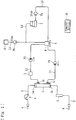
Fig. 1 is a schematic diagram of a blood purification apparatus according to a first embodiment of the present invention. -
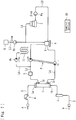
Fig. 2 is a schematic diagram of the blood purification apparatus in a treatment state. -
Fig. 3 is a schematic diagram of the blood purification apparatus in a purification state. -
Fig. 4 is a schematic diagram illustrating an embodiment in which a substitution-fluid supply device is connected to a dialysate circulation line. -
Fig. 5 is a schematic diagram of a blood purification apparatus according to a second embodiment of the present invention. -
Fig. 6 is a schematic diagram of the blood purification apparatus in a treatment state. -
Fig. 7 is a schematic diagram of the blood purification apparatus in another treatment state (at the time of ultrafiltration). -
Fig. 8 is a schematic diagram of the blood purification apparatus in a purification state. -
Fig. 9 is a schematic diagram of a blood purification apparatus according to a third embodiment of the present invention. -
Fig. 10 is a schematic diagram of the blood purification apparatus, with a first circulation-route system being in a treatment state and a second circulation-route system being in a stopped state. -
Fig. 11 is a schematic diagram of the blood purification apparatus, with the first circulation-route system being in a purification state and the second circulation-route system being in the treatment state. -
Fig. 12 is a schematic diagram of the blood purification apparatus, with the first circulation-route system being in the treatment state and the second circulation-route system being in the purification state. -
Fig. 13 is a schematic diagram of another embodiment of the blood purification apparatus (including a duplex pump). -
Fig. 14 is a schematic diagram of a blood purification apparatus according to a fourth embodiment of the present invention. -
Fig. 15 is a schematic diagram of the blood purification apparatus in a treatment state. -
Fig. 16 is a schematic diagram of the blood purification apparatus in a purification state. -
Fig. 17 is a schematic diagram of an embodiment in which a detour line is connected to a dialysate introduction line. - Embodiments of the present invention will now be described specifically with reference to the drawings.
- A blood purification apparatus according to a first embodiment is applied to a hemodialysis apparatus and includes, as illustrated in
Fig. 1 , a blood circuit in which anarterial blood circuit 2 and avenous blood circuit 3 are connected to adialyzer 1 serving as a blood purification device, astorage device 6, a dialysate circulation line including a dialysate introduction line L1 and a dialysate drain line L2, pumps P1 and P2, a waste-matter-concentration measurement device S, adialysate purification device 7, a substitution-fluid supply device 8, and acontrol device 10. - The
dialyzer 1 has non-illustrated blood purification membranes (hollow-fiber hemodialysis membranes in the present embodiment, or flat-film hemodialysis membranes or the like) therein and is provided with a blood introduction port 1a from which blood is introduced, ablood delivery port 1b from which the blood thus introduced is delivered, adialysate introduction port 1c from which dialysate is introduced, and adialysate drain port 1d from which the dialysate thus introduced is drained. Thedialyzer 1 purifies the blood by bringing the dialysate into contact, through the hollow fiber membranes, with the blood introduced thereinto from the blood introduction port 1a. - The
arterial blood circuit 2 is chiefly formed of a flexible tube, with one end thereof connected to the blood introduction port 1a of thedialyzer 1, thereby introducing blood collected from a blood vessel of a patient into the hollow fiber membranes provided in thedialyzer 1. The other end of thearterial blood circuit 2 is provided with a connector for attaching an arterial (blood-removal-side or blood-collection-side) puncture needle a, and is also provided with ablood pump 4. Theblood pump 4 is a peristaltic pump (configured to squeeze the flexible tube when rotated in the normal direction, thereby causing the blood to flow from the side of the arterial puncture needle a toward the blood introduction port 1a of the dialyzer 1). - The
venous blood circuit 3 is chiefly formed of a flexible tube, as with thearterial blood circuit 2, with one end thereof connected to theblood delivery port 1b of thedialyzer 1, thereby delivering the blood having flowed through the hollow fiber membranes. The other end of thevenous blood circuit 3 is provided with a connector for attaching a venous (blood-returning-side) puncture needle b, and is also provided with a venous air-trap chamber 5 for bubble removal at a halfway position thereof. That is, the blood of the patient collected from the arterial puncture needle a flows through thearterial blood circuit 2, reaches thedialyzer 1, is purified therein, flows through thevenous blood circuit 3, and returns into the body of the patient through the venous puncture needle b. Thus, the blood extracorporeally circulates. In this specification, the side of the puncture needle provided for blood removal (collection) is referred to as the "arterial" side, and the side of the puncture needle provided for returning the blood is referred to as the "venous" side. The "arterial" side and the "venous" side are not defined on the basis of which of the artery and the vein is to be the object of puncture. - An end of the dialysate introduction line L1 and an end of the dialysate drain line L2 are connected to the
dialysate introduction port 1c and thedialysate drain port 1d, respectively, of thedialyzer 1. The dialysate introduced into thedialyzer 1 through the dialysate introduction line L1 flows outside the hollow fiber membranes and is allowed to be drained through the dialysate drain line L2. Thus, the inside of each of the hollow fiber membranes (purification membranes) provided in thedialyzer 1 forms a blood flow route in which blood is allowed to flow, whereas the outside of each of the hollow fiber membranes forms a dialysate flow route in which dialysate is allowed to flow. - The dialysate introduction line L1 and the dialysate drain line L2 are also connected to the
storage device 6 that is capable of storing a predetermined amount of dialysate necessary for blood purification treatment. The dialysate introduction line L1 is provided with the pump P1, and the dialysate drain line L2 is provided with the pump P2. Thestorage device 6 is formed of a storage tank, a storage bag, or the like that is capable of storing a predetermined amount of dialysate. When the pumps P1 and P2 are activated, the dialysate in thestorage device 6 is introduced into thedialyzer 1 through the dialysate introduction line L1 and waste liquid (dialysate containing waste matter) discharged from thedialyzer 1 is drained into thestorage device 6. - Thus, the dialysate introduction line L1 and the dialysate drain line L2 form a dialysate circulation line through which the dialysate is allowed to circulate such that the dialysate in the
storage device 6 is introduced into thedialyzer 1 and the waste liquid from thedialyzer 1 is drained into thestorage device 6. With the activation of theblood pump 4, the blood of the patient extracorporeally circulates, and the dialysate circulates through the dialysate circulation line, whereby blood purification treatment (dialysis treatment) is performed. In the present embodiment, if the flow rate of the pump P2 is set to a greater value than the flow rate of the pump P1, ultrafiltration (removal of water from the blood flowing in the blood flow routes by ultrafiltering the blood through the hollow fiber membranes into the dialysate flow routes) can be performed. - The dialysate drain line L2 is provided with the waste-matter-concentration measurement device S that is capable of measuring the concentration of waste matter in the dialysate circulating through the dialysate circulation line. The waste-matter-concentration measurement device S is formed of, for example, a waste-liquid-concentration sensor attached to the dialysate drain line L2 and is capable of detecting the concentration of the waste liquid (the concentration of waste matter) drained from the
dialyzer 1 during blood purification and thus monitoring the efficiency of blood purification. The waste-matter-concentration measurement device S according to the present embodiment is capable of applying light to the circulating dialysate and receiving the light transmitted through the dialysate. The waste-matter-concentration measurement device S is capable of measuring the concentration of waste matter on the basis of the voltage generated in accordance with the intensity of the light received. Alternatively, a waste-matter-concentration measurement device of another type may be employed, as long as the device is capable of measuring the concentration of waste matter. - The
dialysate purification device 7 is a so-called column that is capable of adsorbing waste matter contained in the dialysate. Thedialysate purification device 7 is configured to purify the dialysate circulating through the dialysate circulation line. Thedialysate purification device 7 includes, for example, a container including a plurality of layers stacked thereinside in the vertical direction. The layers include a layer containing activated carbon for adsorbing waste matter (organic metabolite) contained in the dialysate; a purification layer that adsorbs noble metals, oxides, and particles; a decomposition layer that decomposes urea; a layer containing zirconium orthophosphate that adsorbs Mg2+, K+, NH4 +, and Ca2+ from the dialysate and releases H+ and Na+; a layer containing zirconium oxide that adsorbs phosphorus and fluorine from the dialysate and releases acetate; and so forth. - The
dialysate purification device 7 has an introduction port from which dialysate is introduced into the layers provided thereinside, and a delivery port from which the dialysate having flowed through the layers thereinside is delivered. A flow route L3 that guides the dialysate from thestorage device 6 into thedialysate purification device 7 is provided between the introduction port and thestorage device 6. A flow route L4 that guides the dialysate purified by thedialysate purification device 7 into thestorage device 6 is provided between the delivery port and thestorage device 6. The flow route L3 is provided with a pump Pa. When the pump Pa is activated, the dialysate in thestorage device 6 is introduced into thedialysate purification device 7 and the dialysate purified with the adsorption of waste matter by thedialysate purification device 7 is returned into thestorage device 6. Thus, the dialysate can circulate. - The substitution-
fluid supply device 8 is connected to the flow route L4 with a substitution-fluid supply line L5 interposed therebetween. The substitution-fluid supply line L5 is provided with a pump Pb. The substitution-fluid supply device 8 stores a predetermined amount of substitution fluid containing electrolytes (Mg2+, K+, Ca2+, and so forth) necessary for blood purification treatment (dialysis treatment). When the pump Pb is activated, the substitution fluid can be supplied to thestorage device 6 through the flow route L4. The substitution-fluid supply device 8 (the same as those employed in the other embodiments) only needs to be capable of supplying substitution fluid to the dialysate before the dialysate purified by thedialysate purification device 7 reaches the dialyzer 1 (the blood purification device). In the present embodiment, a weighingmachine 9 capable of weighing the dialysate stored in thestorage device 6 is provided so that the amount of substitution fluid supplied from the substitution-fluid supply device 8 can be measured. - The
control device 10 is, for example, a microcomputer or the like provided in the apparatus body. Thecontrol device 10 is capable of selectively activating or stopping actuators such as theblood pump 4, the pumps P1 and P2, and the pumps Pa and Pb and is electrically connected to the weighingmachine 9 and sensors such as the waste-product-concentration measurement device S. Blood purification treatment is performed under the control of thecontrol device 10. - In the present embodiment, a treatment state (see
Fig. 2 ) in which the dialysate circulating through the dialysate circulation line (the dialysate introduction line L1 and the dialysate drain line L2) is allowed to be introduced into thedialyzer 1 without flowing through thedialysate purification device 7 and a purification state (seeFig. 3 ) in which the dialysate circulated through the dialysate circulation line (the dialysate introduction line L1 and the dialysate drain line L2) is allowed to be purified by thedialysate purification device 7 are taken switchably. After the start of the treatment state, if a predetermined condition is satisfied, the purification state is taken. - In the treatment state, as illustrated in
Fig. 2 , the pumps P1 and P2 are activated, but the pumps Pa and Pb are stopped, whereby the dialysate in thestorage device 6 circulates through the dialysate introduction line L1 and the dialysate drain line L2. Thus, thedialyzer 1 performs blood purification treatment. In the purification state, as illustrated inFig. 3 , the pumps P1 and P2 are stopped, but the pump Pa is activated, whereby the dialysate in thestorage device 6 circulates through the flow routes L3 and L4. Thus, thedialysate purification device 7 purifies the dialysate. - In the purification state, the pump Pb is also activated. When the weighing
machine 9 detects the supply of a predetermined amount of substitution fluid to thestorage device 6, the pump Pb is stopped. Thus, the electrolytes adsorbed by thedialysate purification device 7 in the purification state can be resupplied to the dialysate to be made to circulate. Hence, preferable blood purification treatment can be performed continuously. - In the present embodiment, the predetermined condition for taking the purification state after the start of the treatment state is the reaching of the concentration of waste matter measured by the waste-matter-concentration measurement device S to a predetermined concentration after the start of the treatment state. That is, after the start of the treatment state, when the concentration of waste matter measured by the waste-matter-concentration measurement device S reaches a predetermined concentration (a predetermined concentration at which the dialysate needs to be purified), the purification state is taken. Thus, the dialysate in the
storage device 6 is purified by thedialysate purification device 7. - In the purification state, when the concentration of waste matter measured by the waste-matter-concentration measurement device S reaches a predetermined concentration (a predetermined concentration that is reached when the dialysate has been purified), the treatment state is taken again, whereby the dialysate in the
storage device 6 circulates through the flow routes L3 and L4 so as to be purified by thedialysate purification device 7. In the present embodiment, the treatment state and the purification state are taken alternately during blood purification treatment. - The predetermined condition for taking the purification state after the start of the treatment state is not limited to the above-described reaching of the concentration of waste matter measured by the waste-matter-concentration measurement device S to the predetermined concentration, and may be an estimated time taken for the concentration of waste matter in the dialysate circulating through the dialysate circulation line (the dialysate introduction line L1 and the dialysate drain line L2) to reach the predetermined concentration (the predetermined concentration at which the dialysate needs to be purified) after the start of the treatment state. In such a case, it is preferable that, in the purification state, the treatment state be taken again at the elapse of the estimated time taken for the concentration of waste matter in the dialysate to reach the predetermined concentration (the predetermined concentration that is reached when the dialysate has been purified).
- According to the first embodiment, the treatment state in which the dialysate circulating through the dialysate circulation line (the dialysate introduction line L1 and the dialysate drain line L2) is allowed to be introduced into the
dialyzer 1 without flowing through thedialysate purification device 7 and the purification state in which the dialysate circulated through the dialysate circulation line (the dialysate introduction line L1 and the dialysate drain line L2) is allowed to be purified by thedialysate purification device 7 are taken switchably. Furthermore, if the predetermined condition is satisfied after the start of the treatment state, the purification state is taken. Therefore, the efficiency of dialysate purification can be improved, and the reduction in the amount of electrolytes in the dialysate that are necessary for the treatment can be suppressed. Furthermore, according to the present embodiment, the amount of substitution fluid used for resupplying electrolytes that are adsorbed by thedialysate purification device 7 can be reduced. - Furthermore, the treatment state and the purification state are taken alternately during blood purification treatment. Therefore, blood purification treatment can be performed regularly with purified dialysate. Furthermore, the substitution-
fluid supply device 8 capable of supplying to thestorage device 6 the substitution fluid containing electrolytes that are necessary for blood purification treatment is provided. Therefore, the occurrence of shortage of electrolytes in the dialysate during blood purification treatment can be prevented. - Furthermore, the waste-matter-concentration measurement device S capable of measuring the concentration of waste matter contained in the dialysate circulating through the dialysate circulation line (the dialysate introduction line L1 and the dialysate drain line L2) is provided, and the predetermined condition for taking the purification state after the start of the treatment state is defined as the reaching of the concentration of waste matter measured by the waste-matter-concentration measurement device S to the predetermined concentration after the start of the treatment state. Therefore, the switching from the treatment state to the purification state can be realized assuredly and smoothly.
- If the predetermined condition for taking the purification state after the start of the treatment state is defined as the estimated time taken for the concentration of waste matter in the dialysate circulating through the dialysate circulation line (the dialysate introduction line L1 and the dialysate drain line L2) to reach the predetermined concentration after the start of the treatment state, the switching from the treatment state to the purification state can be realized simply and easily. If the predetermined condition is defined as the estimated time, the switching from the treatment state to the purification state can be realized even in a blood purification apparatus that does not include the waste-matter-concentration measurement device S.
- In the present embodiment, the substitution-fluid supply line L5 is connected to the flow route L4, whereby the substitution fluid in the substitution-
fluid supply device 8 can be supplied to thestorage device 6 through the flow route L4. Alternatively, as illustrated inFig. 4 for example, the substitution-fluid supply line L5 may be connected to the dialysate drain line L2 so that the substitution fluid in the substitution-fluid supply device 8 can be supplied to thestorage device 6 through the dialysate drain line L2. - Now, a blood purification apparatus according to a second embodiment of the present invention will be described.
- The blood purification apparatus according to the present embodiment is applied to a hemodialysis apparatus, as with the case of the above embodiment, and includes, as illustrated in
Fig. 5 , a blood circuit in which anarterial blood circuit 2 and avenous blood circuit 3 are connected to adialyzer 1 serving as a blood purification device, astorage device 6, a dialysate circulation line including a dialysate introduction line L1 and a dialysate drain line L2, a duplex pump P, an ultrafiltration pump Pc, a waste-matter-concentration measurement device S, adialysate purification device 7, a substitution-fluid supply device 8, and acontrol device 10. Elements that are the same as those employed in the above embodiment are denoted by corresponding ones of the reference numerals, and detailed description of such elements is omitted. - The duplex pump P is provided over the dialysate introduction line L1 and the dialysate drain line L2. The duplex pump P introduces the dialysate in the
storage device 6 into thedialyzer 1 and drains the dialysate having undergone dialysis from thedialyzer 1 into thestorage device 6. The dialysate drain line L2 is provided with a flow route L6 through which dialysate is allowed to flow. The flow route L6 is connected to the dialysate drain line L2 on the upstream side (nearer to the dialyzer 1) with respect to the duplex pump P. The flow route L6 is provided with the ultrafiltration pump Pc. - The flow route L6 is provided at a distal end thereof with a
dialysate drain device 11 for draining the dialysate to the outside of the apparatus. When the ultrafiltration pump Pc is activated, the dialysate in the dialysate drain line L2 flows into the flow route L6 and reaches thedialysate drain device 11, from which the dialysate is drained to the outside of the apparatus. With the activation of the ultrafiltration pump Pc, the flow rate of the dialysate drained from thedialyzer 1 becomes greater than the flow rate of the dialysate introduced into thedialyzer 1, whereby ultrafiltration can be performed. - In the present embodiment, a treatment state (see
Figs. 6 and7 ) in which the dialysate circulating through the dialysate circulation line (the dialysate introduction line L1 and the dialysate drain line L2) is allowed to be introduced into thedialyzer 1 without flowing through thedialysate purification device 7 and a purification state (seeFig. 8 ) in which the dialysate circulated through the dialysate circulation line (the dialysate introduction line L1 and the dialysate drain line L2) is allowed to be purified by thedialysate purification device 7 are taken switchably. After the start of the treatment state, if a predetermined condition is satisfied, the purification state is taken. - In the treatment state, as illustrated in
Fig. 6 , the duplex pump P is activated, but the pumps Pa and Pb and the ultrafiltration pump Pc are stopped, whereby the dialysate in thestorage device 6 circulates through the dialysate introduction line L1 and the dialysate drain line L2. Thus, thedialyzer 1 performs blood purification treatment. In the treatment state, if the ultrafiltration pump Pc is activated as illustrated inFig. 7 , ultrafiltration can be performed. - In the purification state, as illustrated in
Fig. 8 , the duplex pump P and the ultrafiltration pump Pc are stopped, but the pump Pa is activated, whereby the dialysate in thestorage device 6 circulates through the flow routes L3 and L4. Thus, thedialysate purification device 7 purifies the dialysate. In the purification state, the pump Pb is also activated. When the weighingmachine 9 detects the supply of a predetermined amount of substitution fluid to thestorage device 6, the pump Pb is stopped. Thus, the electrolytes adsorbed by thedialysate purification device 7 in the purification state can be resupplied to the dialysate to be made to circulate. Hence, preferable blood purification treatment can be performed continuously. - As with the case of the above embodiment, the predetermined condition for taking the purification state after the start of the treatment state is the reaching of the concentration of waste matter measured by the waste-matter-concentration measurement device S to the predetermined concentration after the start of the treatment state. That is, after the start of the treatment state, when the concentration of waste matter measured by the waste-matter-concentration measurement device S reaches a predetermined concentration (a predetermined concentration at which the dialysate needs to be purified), the purification state is taken. Thus, the dialysate in the
storage device 6 is purified by thedialysate purification device 7. - In the purification state, when the concentration of waste matter measured by the waste-matter-concentration measurement device S reaches a predetermined concentration (a predetermined concentration that is reached when the dialysate has been purified), the treatment state is taken again, whereby the dialysate in the
storage device 6 circulates through the flow routes L3 and L4 so as to be purified by thedialysate purification device 7. In the present embodiment, the treatment state and the purification state are taken alternately during blood purification treatment. - The predetermined condition for taking the purification state after the start of the treatment state is not limited to the above-described reaching of the concentration of waste matter measured by the waste-matter-concentration measurement device S to the predetermined concentration, and may be an estimated time taken for the concentration of waste matter in the dialysate circulating through the dialysate circulation line (the dialysate introduction line L1 and the dialysate drain line L2) to reach the predetermined concentration (the predetermined concentration at which the dialysate needs to be purified) after the start of the treatment state. In such a case, it is preferable that, in the purification state, the treatment state be taken again at the elapse of the estimated time taken for the concentration of waste matter in the dialysate to reach the predetermined concentration (the predetermined concentration that is reached when the dialysate has been purified).
- According to the second embodiment, the treatment state in which the dialysate circulating through the dialysate circulation line (the dialysate introduction line L1 and the dialysate drain line L2) is allowed to be introduced into the
dialyzer 1 without flowing through thedialysate purification device 7 and the purification state in which the dialysate circulated through the dialysate circulation line (the dialysate introduction line L1 and the dialysate drain line L2) is allowed to be purified by thedialysate purification device 7 are taken switchably. Furthermore, if the predetermined condition is satisfied after the start of the treatment state, the purification state is taken. Therefore, the efficiency of dialysate purification can be improved, and the reduction in the amount of electrolytes in the dialysate that are necessary for the treatment can be suppressed. Furthermore, according to the present embodiment, the amount of substitution fluid used for resupplying electrolytes that are adsorbed by thedialysate purification device 7 can be reduced. - Furthermore, the treatment state and the purification state are taken alternately during blood purification treatment. Therefore, blood purification treatment can be performed regularly with purified dialysate. Furthermore, the substitution-
fluid supply device 8 capable of supplying to thestorage device 6 the substitution fluid containing electrolytes that are necessary for blood purification treatment is provided. Therefore, the occurrence of shortage of electrolytes in the dialysate during blood purification treatment can be prevented. - Furthermore, the waste-matter-concentration measurement device S capable of measuring the concentration of waste matter contained in the dialysate circulating through the dialysate circulation line (the dialysate introduction line L1 and the dialysate drain line L2) is provided, and the predetermined condition for taking the purification state after the start of the treatment state is defined as the reaching of the concentration of waste matter measured by the waste-matter-concentration measurement device S to the predetermined concentration after the start of the treatment state. Therefore, the switching from the treatment state to the purification state can be realized assuredly and smoothly.
- If the predetermined condition for taking the purification state after the start of the treatment state is defined as the estimated time taken for the concentration of waste matter in the dialysate circulating through the dialysate circulation line (the dialysate introduction line L1 and the dialysate drain line L2) to reach the predetermined concentration after the start of the treatment state, the switching from the treatment state to the purification state can be realized simply and easily. If the predetermined condition is defined as the estimated time, the switching from the treatment state to the purification state can be realized even in a blood purification apparatus that does not include the waste-matter-concentration measurement device S.
- Now, a blood purification apparatus according to a third embodiment of the present invention will be described.
- The blood purification apparatus according to the present embodiment is applied to a hemodialysis apparatus, as with the cases of the above embodiments, and includes, as illustrated in
Fig. 9 , a blood circuit in which anarterial blood circuit 2 and avenous blood circuit 3 are connected to adialyzer 1 serving as a blood purification device, afirst storage device 6a and asecond storage device 6b, a dialysate circulation line (a first circulation-route system and a second circulation-route system) including a dialysate introduction line L1 and a dialysate drain line L2, pumps P1 and P2, a waste-matter-concentration measurement device S, adialysate purification device 7, a substitution-fluid supply device 8, and acontrol device 10. Elements that are the same as those employed in either of the above embodiments are denoted by corresponding ones of the reference numerals, and detailed description of such elements is omitted. - The
first storage device 6a and thesecond storage device 6b are each a tank or the like in which a predetermined amount of dialysate is stored. The blood purification apparatus includes a flow route L1a connected to thefirst storage device 6a and to the dialysate introduction line L1 and through which the dialysate is allowed to flow, a flow route L2a connected to thefirst storage device 6a and to the dialysate drain line L2 and through which the dialysate is allowed to flow, a flow route L1b connected to thesecond storage device 6b and to the dialysate introduction line L1 and through which the dialysate is allowed to flow, and a flow route L2b connected to thesecond storage device 6b and to the dialysate drain line L2 and through which the dialysate is allowed to flow. - The flow route L1a and the flow route L1b are provided with electromagnetic valves V1 and V2, respectively. The flow route L2a and the flow route L2b are provided with electromagnetic valves V3 and V4, respectively. The
control device 10 is capable of controlling the opening and the closing of any of the electromagnetic valves. When the electromagnetic valves V1 and V3 are opened with the electromagnetic valves V2 and V4 being closed, the flow route L1a, the dialysate introduction line L1, the dialysate drain line L2, and the flow route L2a form a first circulation-route system through which the dialysate in thefirst storage device 6a is allowed to circulate via thedialyzer 1. When the electromagnetic valves V1 and V3 are closed with the electromagnetic valves V2 and V4 being open, the flow route L1b, the dialysate introduction line L1, the dialysate drain line L2, and the flow route L2b form a second circulation-route system through which the dialysate in thesecond storage device 6b is allowed to circulate via thedialyzer 1. That is, the dialysate circulation line having thefirst storage device 6a forms the first circulation-route system, and the dialysate circulation line having thesecond storage device 6b forms the second circulation-route system. - The
first storage device 6a is connected to the flow route L3 with a flow route L3a, through which the dialysate is allowed to flow, interposed therebetween and is also connected to a flow route L5 with a flow route L5a, through which the dialysate is allowed to flow, interposed therebetween. Thesecond storage device 6b is connected to the flow route L3 with a flow route L3b, through which the dialysate is allowed to flow, interposed therebetween and is also connected to the flow route L5 with a flow route L5b, through which the dialysate is allowed to flow, interposed therebetween. The flow route L4 extending from thedialysate purification device 7 is connected to the flow route L5. The flow route L3a and the flow route L3b are provided with electromagnetic valves V5 and V6, respectively. The flow route L5a and the flow route L5b are provided with electromagnetic valves V7 and V8, respectively. Thecontrol device 10 is capable of controlling the opening and the closing of any of the electromagnetic valves. - In the present embodiment, when one of the first circulation-route system and the second circulation-route system is in the treatment state, the other is in the purification state. Specifically, as illustrated in
Figs. 10 and12 , when the electromagnetic valves V1, V3, V6, and V8 are opened with the electromagnetic valves V2, V4, V5, and V7 being closed, the first circulation-route system (the dialysate circulation line having thefirst storage device 6a) takes the treatment state, whereas the second circulation-route system (the dialysate circulation line having thesecond storage device 6b) takes the purification state (note thatFig. 10 illustrates a stopped state where the pumps Pa and Pb are stopped). On the other hand, as illustrated inFig. 11 , when the electromagnetic valves V2, V4, V5, and V7 are opened with the electromagnetic valves V1, V3, V6, and V8 being closed, the first circulation-route system takes the purification state, whereas the second circulation-route system takes the treatment state. - In the first circulation-route system and the second circulation-route system, as with the cases of the above embodiments, the purification state is taken if a predetermined condition is satisfied after the start of the treatment state. The predetermined condition is the same as those described in the above embodiments. Specifically, as illustrated in
Fig. 10 , when the pumps P1 and P2 are activated with the pumps Pa and Pb being stopped and the electromagnetic valves V1, V3, V6, and V8 are opened with the electromagnetic valves V2, V4, V5, and V7 being closed, the first circulation-route system takes the treatment state (in this case, the second circulation-route system is in the stopped state because purification is not necessary yet) . - If the predetermined condition is satisfied after the first circulation-route system starts to take the treatment state, when the pumps P1 and P2 and the pumps Pa and Pb are activated and the electromagnetic valves V2, V4, V5, and V7 are opened with the electromagnetic valves V1, V3, V6, and V8 being closed as illustrated in
Fig. 11 , the first circulation-route system takes the purification state, whereas the second circulation-route system takes the treatment state. If the predetermined condition is satisfied after the second circulation-route system starts to take the treatment state, when the pumps P1 and P2 and the pumps Pa and Pb are activated and the electromagnetic valves V1, V3, V6, and V8 are opened with the electromagnetic valves V2, V4, V5, and V7 being closed as illustrated inFig. 12 , the first circulation-route system takes the treatment state, whereas the second circulation-route system takes the purification state. - As described above, when one of the first circulation-route system and the second circulation-route system is in the treatment state, the other is in the purification state (in the present embodiment, immediately after the start of the treatment and when the first circulation-route system is in the treatment state, the second circulation-route system is still stopped). That is, the treatment state and the purification state are taken alternately as illustrated in
Figs. 11 and12 during blood purification treatment. Thus, the dialysate can be purified while the blood purification treatment is performed continuously. - According to the third embodiment, for each of the first circulation-route system and the second circulation-route system, the treatment state in which the dialysate circulating through the dialysate circulation line (the dialysate introduction line L1 and the dialysate drain line L2) is allowed to be introduced into the
dialyzer 1 without flowing through thedialysate purification device 7 and the purification state in which the dialysate circulated through the dialysate circulation line (the dialysate introduction line L1 and the dialysate drain line L2) is allowed to be purified by thedialysate purification device 7 are taken switchably. Furthermore, if the predetermined condition is satisfied after the start of the treatment state, the purification state is taken. Therefore, the efficiency of dialysate purification can be improved, and the reduction in the amount of electrolytes in the dialysate that are necessary for the treatment can be suppressed. Furthermore, according to the present embodiment, the amount of substitution fluid used for resupplying electrolytes that are adsorbed by thedialysate purification device 7 can be reduced. - Furthermore, the treatment state and the purification state are taken alternately during blood purification treatment. Therefore, blood purification treatment can be performed regularly with purified dialysate. Furthermore, the substitution-
fluid supply device 8 capable of supplying to thestorage device 6 the substitution fluid containing electrolytes that are necessary for blood purification treatment is provided. Therefore, the occurrence of shortage of electrolytes in the dialysate during blood purification treatment can be prevented. - In the above third embodiment, as illustrated in
Fig. 13 , the pumps P1 and P2 may be replaced with the duplex pump P provided over the dialysate introduction line L1 and the dialysate drain line L2, as with the case of the second embodiment, and a flow route L6 provided with the ultrafiltration pump Pc may be provided in such a manner as to extend from the dialysate drain line L2. In such a case, with the activation of the ultrafiltration pump Pc, the flow rate of the dialysate drained from thedialyzer 1 becomes greater than the flow rate of the dialysate introduced into thedialyzer 1, whereby ultrafiltration can be performed. As illustrated inFig. 13 , it is preferable to provide an electromagnetic valve V9 to the flow route L6 and to open the electromagnetic valve V9 at the time of ultrafiltration. - Now, a blood purification apparatus according to a fourth embodiment of the present invention will be described.
- The blood purification apparatus according to the present embodiment is applied to a hemodialysis apparatus, as with the cases of the above embodiments, and includes, as illustrated in
Fig. 14 , a blood circuit in which anarterial blood circuit 2 and avenous blood circuit 3 are connected to adialyzer 1 serving as a blood purification device, astorage device 6, a dialysate circulation line including a dialysate introduction line L1 and a dialysate drain line L2, detour lines L7 and L8, pumps P1 and P2, a waste-matter-concentration measurement device S, adialysate purification device 7, a substitution-fluid supply device 8, and acontrol device 10. Elements that are the same as those employed in any of the above embodiments are denoted by corresponding ones of the reference numerals, and detailed description of such elements is omitted. - The detour lines L7 and L8 form a flow route that allows the dialysate flowing in the dialysate circulation line (in the present embodiment, the dialysate drain line L2, which is one of the dialysate introduction line L1 and the dialysate drain line L2 that form the dialysate circulation line) to detour therefrom and that is provided with the
dialysate purification device 7. The detour line L7 is provided with an electromagnetic valve V10. The dialysate introduction line L1 is provided with an electromagnetic valve V11 at a position thereof between the connection to the detour line L7 and the connection to the detour line L8. - In the treatment state, as illustrated in
Fig. 15 , the electromagnetic valve V10 is closed but the electromagnetic valve V11 is opened, whereby the flow into the detour lines L7 and L8 is prevented. In the purification state, as illustrated inFig. 16 , the electromagnetic valve V10 is opened but the electromagnetic valve V11 is closed, whereby the dialysate is allowed to flow into the detour lines L7 and L8 and to be purified by thedialysate purification device 7. - In the present embodiment, as with the cases of the above embodiments, if the predetermined condition is satisfied after the start of the treatment state (see
Fig. 15 ), the purification state (seeFig. 16 ) is taken. The predetermined condition is the same as those described in the above embodiments. Specifically, in the treatment state, as illustrated inFig. 15 , the pumps P1 and P2 are activated but the pump Pb is stopped, and the electromagnetic valve V10 is closed but the electromagnetic valve V11 is opened. Thus, the dialysate in thestorage device 6 flows into the dialysate introduction line L1 and reaches thedialyzer 1, where the blood is purified. Then, the dialysate flows into the dialysate drain line L2, without flowing into the detour lines L7 and L8, and is drained into thestorage device 6. Thus, the dialysate in thestorage device 6 is allowed to circulate through the dialysate introduction line L1 and the dialysate drain line L2. - In the purification state, as illustrated in
Fig. 16 , the pumps P1 and P2 are activated and the pump Pb is also activated, and the electromagnetic valve V10 is opened but the electromagnetic valve V11 is closed. Thus, the dialysate in thestorage device 6 flows into the dialysate introduction line L1 and reaches thedialyzer 1. After the blood is purified with the dialysate thus flowed into thedialyzer 1, the resulting waste liquid flows into the detour lines L7 and L8 and is purified by thedialysate purification device 7. Then, the waste liquid is drained into thestorage device 6 through the dialysate drain line L2. Thus, the dialysate in thestorage device 6 can be purified by thedialysate purification device 7 in the process of circulating through the dialysate introduction line L1 and the dialysate drain line L2. - As described above, the flow into the detour lines L7 and L8 is prevented in the treatment state, whereas the dialysate is allowed to flow into the detour lines L7 and L8 and to be purified by the
dialysate purification device 7 in the purification state. Hence, the dialysate can be purified while being made to flow. Moreover, the dialysate can be purified while blood purification treatment is performed continuously. In the present embodiment, the detour lines L7 and L8 provided with thedialysate purification device 7 are connected to the dialysate drain line L2. Alternatively, as illustrated inFig. 17 , the detour lines L7 and L8 may be connected to the dialysate introduction line L1. Furthermore, the pumps P1 and P2 may be replaced with the duplex pump employed in the second embodiment. - According to the fourth embodiment, the treatment state in which the dialysate circulating through the dialysate circulation line (the dialysate introduction line L1 and the dialysate drain line L2) is allowed to be introduced into the
dialyzer 1 without flowing through thedialysate purification device 7 and the purification state in which the dialysate in the dialysate circulation line (the dialysate introduction line L1 and the dialysate drain line L2) is allowed to be purified by thedialysate purification device 7 are taken switchably. Furthermore, if the predetermined condition is satisfied after the start of the treatment state, the purification state is taken. Therefore, the efficiency of dialysate purification can be improved, and the reduction in the amount of electrolytes in the dialysate that are necessary for the treatment can be suppressed. Furthermore, according to the present embodiment, the amount of substitution fluid used for resupplying electrolytes that are adsorbed by thedialysate purification device 7 can be reduced. Furthermore, the substitution-fluid supply device 8 capable of supplying to thestorage device 6 the substitution fluid containing electrolytes that are necessary for blood purification treatment is provided. Therefore, the occurrence of shortage of electrolytes in the dialysate during blood purification treatment can be prevented. - While the embodiments have been described above, the present invention is not limited thereto. The blood purification apparatus only needs to be capable of taking the purification state if a predetermined condition is satisfied after the start of the treatment state. For example, another predetermined condition different from the predetermined condition employed in the above embodiments may be employed (preferably, the condition is defined with reference to a parameter correlating with the concentration of waste matter in the dialysate). Moreover, the substitution-
fluid supply device 8 or the waste-matter-concentration measurement device S may be omitted. Alternatively, the weighingmachine 9 may be omitted (for example, a predetermined amount of substitution fluid may be supplied by controlling the flow rate of the pump Pb). Moreover, a dialysate-concentration-checking device (such as a conductometer) for checking whether or not the composition of the dialysate is appropriate may be provided. - The present invention is applicable to any blood purification apparatus that is capable of switchably taking a treatment state in which dialysate circulating through a dialysate circulation line is allowed to be introduced into a blood purification device without flowing through a dialysate purification device and a purification state in which the dialysate in the dialysate circulation line is allowed to be purified by the dialysate purification device, the apparatus being configured to take the purification state if a predetermined condition is satisfied after the start of the treatment state. Such an apparatus may have additional functions or the like.
-
- 1
- dialyzer (blood purification device)
- 2
- arterial blood circuit
- 3
- venous blood circuit
- 4
- blood pump
- 5
- venous air-trap chamber
- 6
- storage device
- 7
- dialysate purification device
- 8
- substitution-fluid supply device
- 9
- weighing machine
- 10
- control device
- 11
- drain device
- L1
- dialysate introduction line
- L2
- dialysate drain line
- L3
- flow route
- L4
- flow route
- L5
- substitution-fluid supply line
- L6
- flow route
- L7, L8
- detour line
- S
- waste-matter-concentration measurement device
- P1, P2, Pa, Pb
- pump
- Pc
- ultrafiltration pump
- P
- duplex pump
Claims (7)
- A blood purification apparatus comprising:a blood circuit through which blood of a patient is allowed to extracorporeally circulate;a blood purification device that purifies the blood flowing in the blood circuit;a storage device capable of storing a predetermined amount of dialysate that is necessary for blood purification treatment;a dialysate circulation line through which the dialysate is allowed to circulate by introducing the dialysate in the storage device into the blood purification device and draining waste liquid from the blood purification device into the storage device; anda dialysate purification device that purifies the dialysate in the dialysate circulation line,wherein a treatment state in which the dialysate circulating through the dialysate circulation line is allowed to be introduced into the blood purification device without flowing through the dialysate purification device and a purification state in which the dialysate in the dialysate circulation line is allowed to be purified by the dialysate purification device are taken switchably, and wherein the purification state is taken if a predetermined condition is satisfied after a start of the treatment state.
- The blood purification apparatus according to Claim 1, wherein the treatment state and the purification state are taken alternately during blood purification treatment.
- The blood purification apparatus according to Claim 1 or 2, further comprising a substitution-fluid supply device capable of supplying substitution fluid containing electrolytes that are necessary for blood purification treatment to the dialysate before the dialysate purified by the dialysate purification device reaches the blood purification device.
- The blood purification apparatus according to any of Claims 1 to 3, wherein the predetermined condition is defined as an estimated time taken for a concentration of waste matter in the dialysate circulating through the dialysate circulation line to reach a predetermined concentration after the start of the treatment state.
- The blood purification apparatus according to any of Claims 1 to 3, further comprising a waste-matter-concentration measurement device capable of measuring a concentration of waste matter in the dialysate circulating through the dialysate circulation line, wherein the predetermined condition is defined as reaching of the concentration of waste matter measured by the waste-matter-concentration measurement device to a predetermined concentration after the start of the treatment state.
- The blood purification apparatus according to any of Claims 1 to 5, wherein the storage device includes a first storage device and a second storage device in each of which a predetermined amount of dialysate is stored; wherein the dialysate circulation line includes a first circulation-route system through which the dialysate in the first storage device is allowed to circulate via the blood purification device, and a second circulation-route system through which the dialysate in the second storage device is allowed to circulate via the blood purification device; and wherein when one of the first circulation-route system and the second circulation-route system is in the treatment state, an other is in the purification state.
- The blood purification apparatus according to any of Claims 1 to 5, further comprising a detour line to which the dialysate purification device is provided and that allows the dialysate flowing in the dialysate circulation line to detour, wherein the flow into the detour line is prevented in the treatment state, whereas the dialysate is allowed to flow into the detour line and to be purified by the dialysate purification device in the purification state.
Applications Claiming Priority (2)
| Application Number | Priority Date | Filing Date | Title |
|---|---|---|---|
| JP2016186173A JP6826852B2 (en) | 2016-09-23 | 2016-09-23 | Blood purification device |
| PCT/JP2017/034309 WO2018056400A1 (en) | 2016-09-23 | 2017-09-22 | Blood purification system |
Publications (3)
| Publication Number | Publication Date |
|---|---|
| EP3517149A1 true EP3517149A1 (en) | 2019-07-31 |
| EP3517149A4 EP3517149A4 (en) | 2020-04-29 |
| EP3517149B1 EP3517149B1 (en) | 2021-07-21 |
Family
ID=61689979
Family Applications (1)
| Application Number | Title | Priority Date | Filing Date |
|---|---|---|---|
| EP17853168.7A Active EP3517149B1 (en) | 2016-09-23 | 2017-09-22 | Blood purification system |
Country Status (5)
| Country | Link |
|---|---|
| US (1) | US11413387B2 (en) |
| EP (1) | EP3517149B1 (en) |
| JP (1) | JP6826852B2 (en) |
| CN (1) | CN109789259B (en) |
| WO (1) | WO2018056400A1 (en) |
Families Citing this family (4)
| Publication number | Priority date | Publication date | Assignee | Title |
|---|---|---|---|---|
| JP7144979B2 (en) * | 2018-06-20 | 2022-09-30 | 日機装株式会社 | Blood purification device and method for estimating patient's nutritional status by blood purification device |
| JP7641195B2 (en) * | 2021-07-01 | 2025-03-06 | 日機装株式会社 | Blood Purification Device |
| CN114748717B (en) * | 2022-04-12 | 2023-07-25 | 江苏恰瑞生物科技有限公司 | Blood purifying device with anticoagulation function |
| WO2024043193A1 (en) * | 2022-08-23 | 2024-02-29 | フィジオロガス・テクノロジーズ株式会社 | Target liquid treatment apparatus |
Family Cites Families (125)
| Publication number | Priority date | Publication date | Assignee | Title |
|---|---|---|---|---|
| US4493693A (en) | 1982-07-30 | 1985-01-15 | Baxter Travenol Laboratories, Inc. | Trans-membrane pressure monitoring system |
| JPS60153138U (en) | 1984-03-22 | 1985-10-12 | 横河電機株式会社 | artificial dialysis machine |
| US4531959A (en) | 1984-10-04 | 1985-07-30 | Corning Glass Works | Method and apparatus for coating optical fibers |
| JPS6422357U (en) | 1987-07-31 | 1989-02-06 | ||
| JPH01201263A (en) | 1988-02-06 | 1989-08-14 | Toray Ind Inc | Ultrafiltration control device |
| SE464913B (en) | 1988-03-03 | 1991-07-01 | Gambro Ab | DEVICE FOR PRESSURE TRANSMISSION |
| JPH07120442B2 (en) | 1989-05-30 | 1995-12-20 | 沖電気工業株式会社 | Securities issuing device |
| JPH0373162A (en) | 1989-08-14 | 1991-03-28 | Terumo Corp | Connecting implement and remedial apparatus provided therewith and connecting and dissociating device therefor |
| JPH0399671A (en) * | 1989-09-13 | 1991-04-24 | Saitetsuku Kk | Apparatus controlling amount of ultrafiltration |
| US5336051A (en) | 1989-09-22 | 1994-08-09 | Yehuda Tamari | Inline non-invasive pressure monitoring system for pumps |
| US5927951A (en) | 1989-09-22 | 1999-07-27 | Tamari; Yehuda | Safety devices for peristaltic pumps |
| DE69526613T2 (en) | 1994-07-12 | 2002-08-29 | Medrad, Inc. | Information path control loop for a system that delivers medical fluids |
| US6044691A (en) | 1998-08-26 | 2000-04-04 | Aksys, Ltd. | Blood tubing set integrity tests for extracorporeal circuits |
| US6374084B1 (en) | 1999-02-01 | 2002-04-16 | Avaya Technology Corp. | Method and system for calibrating electronic devices using polynomial fit calibration scheme |
| US6497680B1 (en) | 1999-12-17 | 2002-12-24 | Abbott Laboratories | Method for compensating for pressure differences across valves in cassette type IV pump |
| IT1319785B1 (en) | 2000-01-12 | 2003-11-03 | Gambro Dasco Spa | EMPTYING METHOD OF A BLOOD CIRCUIT IN A DIDIALYSIS AND BLOOD CIRCUIT FOR IMPLEMENTING THE METHOD. |
| JP4643815B2 (en) | 2000-10-04 | 2011-03-02 | テルモ株式会社 | Peritoneal dialysis machine |
| US6689083B1 (en) | 2000-11-27 | 2004-02-10 | Chf Solutions, Inc. | Controller for ultrafiltration blood circuit which prevents hypotension by monitoring osmotic pressure in blood |
| JP2003093503A (en) | 2001-09-25 | 2003-04-02 | Jms Co Ltd | Blood circuit automatic deaeration system |
| JP4352368B2 (en) | 2001-09-27 | 2009-10-28 | 東レ・メディカル株式会社 | Dialysate sampling port |
| US6820490B2 (en) | 2001-10-16 | 2004-11-23 | Neomedix Corporation | Systems and methods for measuring pressure |
| JP4457235B2 (en) | 2001-12-18 | 2010-04-28 | 株式会社北九州バイオフィジックス研究所 | Automatic hemodialysis apparatus and priming method using the apparatus. |
| JP2003265601A (en) | 2002-03-19 | 2003-09-24 | Nikkiso Co Ltd | Blood circuit |
| JP4075040B2 (en) | 2002-03-29 | 2008-04-16 | 株式会社ジェイ・エム・エス | Extracorporeal blood circuit system |
| JP4250712B2 (en) | 2002-06-19 | 2009-04-08 | 株式会社北九州バイオフィジックス研究所 | Automatic hemodialysis machine |
| JP4358736B2 (en) | 2002-06-24 | 2009-11-04 | ガンブロ・ルンディア・エービー | Gas separator |
| JP2004049493A (en) | 2002-07-18 | 2004-02-19 | Jms Co Ltd | Hemodialysis machine and control program for hemodialysis machine |
| JP2004049494A (en) | 2002-07-18 | 2004-02-19 | Jms Co Ltd | Automatic blood return device |
| JP4890761B2 (en) * | 2002-07-19 | 2012-03-07 | バクスター・インターナショナル・インコーポレイテッド | System and method for performing peritoneal dialysis |
| CN100486652C (en) | 2002-09-11 | 2009-05-13 | 弗雷森纽斯医疗护理德国有限责任公司 | Blood return apparatus for use with blood returned from a dialysis machine |
| US6868720B2 (en) | 2002-10-16 | 2005-03-22 | Alcon, Inc. | Testing of pressure sensor in surgical cassette |
| JP3958733B2 (en) | 2002-11-14 | 2007-08-15 | 日機装株式会社 | Blood purification equipment |
| JP4091873B2 (en) | 2003-04-17 | 2008-05-28 | 日機装株式会社 | Dialysis machine |
| US8029454B2 (en) * | 2003-11-05 | 2011-10-04 | Baxter International Inc. | High convection home hemodialysis/hemofiltration and sorbent system |
| JP4286165B2 (en) | 2004-03-10 | 2009-06-24 | 旭化成クラレメディカル株式会社 | Blood purification apparatus priming method and blood purification apparatus |
| WO2005118485A1 (en) | 2004-05-28 | 2005-12-15 | Nephros, Inc. | Multi-use dialysis machine priming and solution delivery device |
| JP4232103B2 (en) | 2004-06-29 | 2009-03-04 | 澁谷工業株式会社 | Blood dewatering device and preparation method thereof |
| JP4868772B2 (en) | 2004-08-24 | 2012-02-01 | 日機装株式会社 | Blood purification equipment |
| JP4397342B2 (en) | 2005-04-04 | 2010-01-13 | 日機装株式会社 | Blood purification equipment |
| JP4726045B2 (en) | 2005-04-08 | 2011-07-20 | 日機装株式会社 | Hemodialysis machine |
| JP5158830B2 (en) | 2005-06-22 | 2013-03-06 | 日機装株式会社 | Dialysis treatment device |
| JP2007020962A (en) | 2005-07-19 | 2007-02-01 | Terumo Corp | Blood component sampling device |
| US8092414B2 (en) | 2005-11-09 | 2012-01-10 | Nxstage Medical, Inc. | Diaphragm pressure pod for medical fluids |
| JP4822258B2 (en) | 2005-11-11 | 2011-11-24 | 日機装株式会社 | Hemodialysis machine |
| CA2630094A1 (en) | 2005-11-15 | 2007-05-24 | Luminous Medical, Inc. | Blood analyte determinations |
| US8011905B2 (en) | 2005-11-17 | 2011-09-06 | Novartis Ag | Surgical cassette |
| JP4798653B2 (en) | 2005-11-18 | 2011-10-19 | 日機装株式会社 | Blood purification equipment |
| JP4889297B2 (en) | 2005-12-19 | 2012-03-07 | 株式会社ジェイ・エム・エス | Hemodialysis machine |
| AU2006331191B2 (en) | 2005-12-29 | 2012-02-02 | Danish Medical Research Aps | Method and apparatus for home dialysis |
| JP4978179B2 (en) | 2006-02-07 | 2012-07-18 | 株式会社ジェイ・エム・エス | Blood purification equipment |
| DK1818664T3 (en) | 2006-02-13 | 2013-08-05 | Hoffmann La Roche | Apparatus for recognizing a pressure change in the liquid path of a micro-dosing device |
| JP2007268257A (en) | 2006-03-10 | 2007-10-18 | Asahi Kasei Medical Co Ltd | Hemodialysis machine |
| DE102006012087B4 (en) | 2006-03-14 | 2008-10-02 | Fresenius Medical Care Deutschland Gmbh | Method for at least partially emptying an extracorporeal blood circulation and hemodialysis machine for use of the method |
| JP4656427B2 (en) | 2006-04-14 | 2011-03-23 | 日機装株式会社 | Liquid level adjustment method for drip chamber for priming liquid |
| JP2007007435A (en) | 2006-08-28 | 2007-01-18 | Kita Kyushu Seimei Joho Kagakuin:Kk | Automatic hemodialysis machine |
| JP3128724U (en) | 2006-09-15 | 2007-01-25 | 川澄化学工業株式会社 | Drip chamber |
| WO2008059305A1 (en) | 2006-11-15 | 2008-05-22 | Gambro Lundia Ab | An apparatus for extracorporeal blood treatment |
| EP2116269B1 (en) * | 2007-02-15 | 2013-10-16 | Asahi Kasei Medical Co., Ltd. | Blood purification system |
| JP4976198B2 (en) | 2007-05-24 | 2012-07-18 | アトムメディカル株式会社 | Medical infusion device |
| JP5370152B2 (en) | 2007-06-29 | 2013-12-18 | 株式会社ジェイ・エム・エス | Hemodialysis machine |
| JP4573860B2 (en) * | 2007-08-22 | 2010-11-04 | 日機装株式会社 | Blood purification equipment |
| US8137553B2 (en) * | 2007-11-29 | 2012-03-20 | Fresenius Medical Care Holdings, Inc. | Priming system and method for dialysis systems |
| JP4281835B2 (en) | 2007-11-06 | 2009-06-17 | 株式会社ジェイ・エム・エス | Hemodialysis machine |
| JP5188780B2 (en) | 2007-11-08 | 2013-04-24 | 日機装株式会社 | Blood purification apparatus and treatment end notification method using the same |
| WO2009064741A1 (en) | 2007-11-12 | 2009-05-22 | Compete, Inc. | Systems and methods for normalizing clickstream data |
| JP5205036B2 (en) | 2007-11-29 | 2013-06-05 | 日機装株式会社 | Blood purification equipment |
| DE602007013824D1 (en) * | 2007-12-03 | 2011-05-19 | Hepa Wash Gmbh | Dialysate REGENERATION UNIT |
| ITBO20070811A1 (en) | 2007-12-10 | 2009-06-11 | Sorin Group Italia Srl | INFUSION GROUP OF A REPLACEMENT SOLUTION FROM A DIALYSIS MACHINE |
| JP5154979B2 (en) | 2008-03-05 | 2013-02-27 | 京浜ハイフロー販売株式会社 | Medical sampling valve |
| JP2009297339A (en) | 2008-06-16 | 2009-12-24 | Nikkiso Co Ltd | Blood purifying device and priming method thereof |
| JP2010000161A (en) | 2008-06-19 | 2010-01-07 | Sepi Koko:Kk | Blood circuit in dialysis and priming method of dialyzer |
| JP2010029376A (en) | 2008-07-28 | 2010-02-12 | Nikkiso Co Ltd | Dialyzer |
| DE102008038097A1 (en) | 2008-08-18 | 2010-02-25 | Fresenius Medical Care Deutschland Gmbh | Cassette for conveying liquids, in particular dialysis liquids |
| JP5231967B2 (en) | 2008-12-11 | 2013-07-10 | 日機装株式会社 | Blood purification equipment |
| JP5294985B2 (en) | 2008-12-16 | 2013-09-18 | 日機装株式会社 | Blood purification apparatus and priming method thereof |
| DE102009008346B4 (en) | 2009-02-11 | 2014-11-13 | Fresenius Medical Care Deutschland Gmbh | A method of removing blood from an extracorporeal blood circuit for a treatment device after completion of a blood treatment session and apparatus for performing the same |
| JP5356853B2 (en) | 2009-02-12 | 2013-12-04 | 日機装株式会社 | Blood purification equipment |
| EP2421581B1 (en) | 2009-04-23 | 2020-02-19 | Fresenius Medical Care Deutschland GmbH | Treatment device for extracorporal blood treatment of a patient |
| JP5594714B2 (en) | 2009-05-27 | 2014-09-24 | 日機装株式会社 | Blood purification equipment |
| JP5337618B2 (en) | 2009-08-04 | 2013-11-06 | 日機装株式会社 | Calibration method of blood pressure removal detecting means and blood purification device |
| JP2011120821A (en) | 2009-12-14 | 2011-06-23 | Nikkiso Co Ltd | Blood purifier |
| ES2539821T3 (en) | 2009-12-28 | 2015-07-06 | Gambro Lundia Ab | Control of an apparatus for fluid transfer to and / or from a subject |
| US9289544B2 (en) | 2009-12-28 | 2016-03-22 | Gambro Lundia Ab | Method and device for detecting a configuration of withdrawal and return devices |
| JP5431199B2 (en) | 2010-02-10 | 2014-03-05 | 日機装株式会社 | Blood purification apparatus and priming method thereof |
| JP5442483B2 (en) | 2010-02-10 | 2014-03-12 | 日機装株式会社 | Blood purification equipment |
| JP5026558B2 (en) | 2010-05-24 | 2012-09-12 | 株式会社ジェイ・エム・エス | Hemodialysis machine |
| JP5693890B2 (en) | 2010-08-05 | 2015-04-01 | 日機装株式会社 | Blood purification equipment |
| EP2601985A4 (en) | 2010-08-05 | 2015-10-07 | Nikkiso Co Ltd | BLOOD PURIFYING DEVICE, AND METHOD FOR FLUID LEAK INSPECTION IN SUCH A DEVICE |
| US8784668B2 (en) | 2010-10-12 | 2014-07-22 | Fresenius Medical Care Holdings, Inc. | Systems and methods for compensation of compliant behavior in regenerative dialysis systems |
| JP5539845B2 (en) | 2010-11-02 | 2014-07-02 | 日機装株式会社 | Blood purification apparatus and priming method thereof |
| JP5529711B2 (en) | 2010-11-02 | 2014-06-25 | 日機装株式会社 | Air trap chamber of blood purification apparatus and priming method of blood purification apparatus |
| JP5621591B2 (en) | 2010-12-29 | 2014-11-12 | ニプロ株式会社 | Blood purification apparatus and automatic priming method for blood circulation circuit thereof |
| JP2012192100A (en) | 2011-03-17 | 2012-10-11 | Nikkiso Co Ltd | Blood purifier |
| JP5699008B2 (en) | 2011-03-17 | 2015-04-08 | 日機装株式会社 | Blood purification equipment |
| JP5681536B2 (en) | 2011-03-17 | 2015-03-11 | 日機装株式会社 | Blood purification equipment |
| JP5707190B2 (en) | 2011-03-17 | 2015-04-22 | 日機装株式会社 | Blood purification equipment |
| JP5153905B2 (en) | 2011-03-24 | 2013-02-27 | 株式会社日本トリム | Dialysate preparation water production equipment |
| JP5813403B2 (en) | 2011-06-23 | 2015-11-17 | 日機装株式会社 | Dialysate extraction device |
| JP5205496B2 (en) | 2011-07-27 | 2013-06-05 | 日機装株式会社 | Dialysate extraction device |
| WO2013027621A1 (en) | 2011-08-22 | 2013-02-28 | 日機装株式会社 | Fluid flow path pressure detection device |
| JP2013048803A (en) | 2011-08-31 | 2013-03-14 | Nikkiso Co Ltd | Blood purification system |
| JP5748280B2 (en) | 2011-09-09 | 2015-07-15 | 日機装株式会社 | Dialysate extraction device |
| JP5914106B2 (en) | 2012-03-30 | 2016-05-11 | 日機装株式会社 | Blood purification equipment |
| JP5479520B2 (en) | 2012-04-05 | 2014-04-23 | 日機装株式会社 | Dialysate extraction device |
| JP6478393B2 (en) | 2012-08-09 | 2019-03-06 | 日機装株式会社 | Blood purification apparatus and priming method thereof |
| EP2712637B1 (en) | 2012-09-28 | 2016-10-19 | Gambro Lundia AB | Extracorporeal blood treatment apparatus and method of setting an extracorporeal blood treatment. |
| JP5469728B1 (en) | 2012-10-19 | 2014-04-16 | 日機装株式会社 | Liquid channel pressure detector |
| JP5734262B2 (en) | 2012-11-14 | 2015-06-17 | 日機装株式会社 | Blood purification system |
| JP6204495B2 (en) | 2013-01-07 | 2017-09-27 | ヘンリー フォード ヘルス システムHenry Ford Health System | Apparatus and method for detecting irregular placement of extracorporeal vascular access needles |
| US9707328B2 (en) * | 2013-01-09 | 2017-07-18 | Medtronic, Inc. | Sorbent cartridge to measure solute concentrations |
| US8918877B1 (en) | 2013-01-29 | 2014-12-23 | Palo Alto Networks, Inc. | Signature compilation on a security device |
| JP6144097B2 (en) | 2013-02-22 | 2017-06-07 | 川澄化学工業株式会社 | Liquid level adjustment device |
| JP5808062B2 (en) | 2013-11-11 | 2015-11-10 | 日機装株式会社 | Blood purification apparatus and priming method thereof |
| US8960010B1 (en) | 2013-12-23 | 2015-02-24 | Fresenius Medical Care Holdings, Inc. | Automatic detection and adjustment of a pressure pod diaphragm |
| US10596309B2 (en) * | 2014-04-25 | 2020-03-24 | Nextkidney Sa | Hemodialysis system |
| WO2015177606A1 (en) | 2014-05-22 | 2015-11-26 | Debiotech S.A. | Home hemodialysis systems |
| JP6305848B2 (en) | 2014-06-27 | 2018-04-04 | 日機装株式会社 | Blood purification equipment |
| JP5851003B1 (en) | 2014-09-12 | 2016-02-03 | 日機装株式会社 | Blood purification equipment |
| JP6517023B2 (en) | 2015-01-23 | 2019-05-22 | 日機装株式会社 | Blood purification device |
| JP6516559B2 (en) | 2015-05-21 | 2019-05-22 | 日機装株式会社 | Blood purification device |
| JP6685089B2 (en) | 2015-06-01 | 2020-04-22 | 日機装株式会社 | Medical fluid pressure detector |
| JP6619575B2 (en) | 2015-07-23 | 2019-12-11 | 日機装株式会社 | Blood purification equipment |
| EP3352811B1 (en) * | 2015-09-25 | 2020-12-09 | Medtronic Inc. | Selective sorbent-based regeneration dialysis systems |
| JP6100865B1 (en) | 2015-10-29 | 2017-03-22 | 日機装株式会社 | Blood purification equipment |
| JP6111351B1 (en) | 2016-01-25 | 2017-04-05 | 日機装株式会社 | Blood purification equipment |
-
2016
- 2016-09-23 JP JP2016186173A patent/JP6826852B2/en active Active
-
2017
- 2017-09-22 WO PCT/JP2017/034309 patent/WO2018056400A1/en not_active Ceased
- 2017-09-22 EP EP17853168.7A patent/EP3517149B1/en active Active
- 2017-09-22 CN CN201780058241.3A patent/CN109789259B/en active Active
-
2019
- 2019-03-21 US US16/360,525 patent/US11413387B2/en active Active
Also Published As
| Publication number | Publication date |
|---|---|
| US11413387B2 (en) | 2022-08-16 |
| JP6826852B2 (en) | 2021-02-10 |
| EP3517149A4 (en) | 2020-04-29 |
| CN109789259B (en) | 2021-10-15 |
| WO2018056400A1 (en) | 2018-03-29 |
| US20190217001A1 (en) | 2019-07-18 |
| JP2018047167A (en) | 2018-03-29 |
| CN109789259A (en) | 2019-05-21 |
| EP3517149B1 (en) | 2021-07-21 |
Similar Documents
| Publication | Publication Date | Title |
|---|---|---|
| EP3069742B1 (en) | Blood purification device and method for priming same | |
| EP2883558B1 (en) | Blood purification device and priming method therefor | |
| US11413387B2 (en) | Blood purification apparatus | |
| CN104203304B (en) | Apparatus for purifying blood | |
| CN103732270B (en) | Apparatus for purifying blood | |
| JP5247864B2 (en) | Blood purification equipment | |
| EP3369441B1 (en) | Blood purification apparatus | |
| WO2014121167A1 (en) | pH AND BUFFER MANAGEMENT SYSTEM FOR HEMODIALYSIS SYSTEMS | |
| JP5399218B2 (en) | Blood purification equipment | |
| JP2011160963A (en) | Dialyzer | |
| EP3269408A1 (en) | Blood purification device | |
| US20200171231A1 (en) | Hemodialysis System | |
| EP3834859B1 (en) | Blood purification apparatus | |
| EP3369443B1 (en) | Blood purification apparatus | |
| JP7114466B2 (en) | Blood purification device and priming method | |
| JP7249147B2 (en) | blood purifier | |
| JP6488048B2 (en) | Blood purification equipment | |
| JP6357496B2 (en) | Blood purification equipment | |
| JP2017006485A (en) | Blood purification apparatus and blood purification system |
Legal Events
| Date | Code | Title | Description |
|---|---|---|---|
| STAA | Information on the status of an ep patent application or granted ep patent |
Free format text: STATUS: THE INTERNATIONAL PUBLICATION HAS BEEN MADE |
|
| PUAI | Public reference made under article 153(3) epc to a published international application that has entered the european phase |
Free format text: ORIGINAL CODE: 0009012 |
|
| STAA | Information on the status of an ep patent application or granted ep patent |
Free format text: STATUS: REQUEST FOR EXAMINATION WAS MADE |
|
| 17P | Request for examination filed |
Effective date: 20190409 |
|
| AK | Designated contracting states |
Kind code of ref document: A1 Designated state(s): AL AT BE BG CH CY CZ DE DK EE ES FI FR GB GR HR HU IE IS IT LI LT LU LV MC MK MT NL NO PL PT RO RS SE SI SK SM TR |
|
| AX | Request for extension of the european patent |
Extension state: BA ME |
|
| DAV | Request for validation of the european patent (deleted) | ||
| DAX | Request for extension of the european patent (deleted) | ||
| A4 | Supplementary search report drawn up and despatched |
Effective date: 20200327 |
|
| RIC1 | Information provided on ipc code assigned before grant |
Ipc: A61M 1/16 20060101AFI20200324BHEP |
|
| GRAP | Despatch of communication of intention to grant a patent |
Free format text: ORIGINAL CODE: EPIDOSNIGR1 |
|
| STAA | Information on the status of an ep patent application or granted ep patent |
Free format text: STATUS: GRANT OF PATENT IS INTENDED |
|
| INTG | Intention to grant announced |
Effective date: 20201109 |
|
| GRAJ | Information related to disapproval of communication of intention to grant by the applicant or resumption of examination proceedings by the epo deleted |
Free format text: ORIGINAL CODE: EPIDOSDIGR1 |
|
| STAA | Information on the status of an ep patent application or granted ep patent |
Free format text: STATUS: REQUEST FOR EXAMINATION WAS MADE |
|
| GRAP | Despatch of communication of intention to grant a patent |
Free format text: ORIGINAL CODE: EPIDOSNIGR1 |
|
| STAA | Information on the status of an ep patent application or granted ep patent |
Free format text: STATUS: GRANT OF PATENT IS INTENDED |
|
| INTC | Intention to grant announced (deleted) | ||
| INTG | Intention to grant announced |
Effective date: 20210323 |
|
| GRAS | Grant fee paid |
Free format text: ORIGINAL CODE: EPIDOSNIGR3 |
|
| GRAA | (expected) grant |
Free format text: ORIGINAL CODE: 0009210 |
|
| STAA | Information on the status of an ep patent application or granted ep patent |
Free format text: STATUS: THE PATENT HAS BEEN GRANTED |
|
| AK | Designated contracting states |
Kind code of ref document: B1 Designated state(s): AL AT BE BG CH CY CZ DE DK EE ES FI FR GB GR HR HU IE IS IT LI LT LU LV MC MK MT NL NO PL PT RO RS SE SI SK SM TR |
|
| REG | Reference to a national code |
Ref country code: GB Ref legal event code: FG4D |
|
| REG | Reference to a national code |
Ref country code: CH Ref legal event code: EP |
|
| REG | Reference to a national code |
Ref country code: DE Ref legal event code: R096 Ref document number: 602017042677 Country of ref document: DE |
|
| REG | Reference to a national code |
Ref country code: AT Ref legal event code: REF Ref document number: 1412002 Country of ref document: AT Kind code of ref document: T Effective date: 20210815 |
|
| REG | Reference to a national code |
Ref country code: IE Ref legal event code: FG4D |
|
| REG | Reference to a national code |
Ref country code: SE Ref legal event code: TRGR |
|
| REG | Reference to a national code |
Ref country code: LT Ref legal event code: MG9D |
|
| REG | Reference to a national code |
Ref country code: NL Ref legal event code: MP Effective date: 20210721 |
|
| REG | Reference to a national code |
Ref country code: AT Ref legal event code: MK05 Ref document number: 1412002 Country of ref document: AT Kind code of ref document: T Effective date: 20210721 |
|
| PG25 | Lapsed in a contracting state [announced via postgrant information from national office to epo] |
Ref country code: HR Free format text: LAPSE BECAUSE OF FAILURE TO SUBMIT A TRANSLATION OF THE DESCRIPTION OR TO PAY THE FEE WITHIN THE PRESCRIBED TIME-LIMIT Effective date: 20210721 Ref country code: FI Free format text: LAPSE BECAUSE OF FAILURE TO SUBMIT A TRANSLATION OF THE DESCRIPTION OR TO PAY THE FEE WITHIN THE PRESCRIBED TIME-LIMIT Effective date: 20210721 Ref country code: ES Free format text: LAPSE BECAUSE OF FAILURE TO SUBMIT A TRANSLATION OF THE DESCRIPTION OR TO PAY THE FEE WITHIN THE PRESCRIBED TIME-LIMIT Effective date: 20210721 Ref country code: RS Free format text: LAPSE BECAUSE OF FAILURE TO SUBMIT A TRANSLATION OF THE DESCRIPTION OR TO PAY THE FEE WITHIN THE PRESCRIBED TIME-LIMIT Effective date: 20210721 Ref country code: PT Free format text: LAPSE BECAUSE OF FAILURE TO SUBMIT A TRANSLATION OF THE DESCRIPTION OR TO PAY THE FEE WITHIN THE PRESCRIBED TIME-LIMIT Effective date: 20211122 Ref country code: NO Free format text: LAPSE BECAUSE OF FAILURE TO SUBMIT A TRANSLATION OF THE DESCRIPTION OR TO PAY THE FEE WITHIN THE PRESCRIBED TIME-LIMIT Effective date: 20211021 Ref country code: NL Free format text: LAPSE BECAUSE OF FAILURE TO SUBMIT A TRANSLATION OF THE DESCRIPTION OR TO PAY THE FEE WITHIN THE PRESCRIBED TIME-LIMIT Effective date: 20210721 Ref country code: LT Free format text: LAPSE BECAUSE OF FAILURE TO SUBMIT A TRANSLATION OF THE DESCRIPTION OR TO PAY THE FEE WITHIN THE PRESCRIBED TIME-LIMIT Effective date: 20210721 Ref country code: BG Free format text: LAPSE BECAUSE OF FAILURE TO SUBMIT A TRANSLATION OF THE DESCRIPTION OR TO PAY THE FEE WITHIN THE PRESCRIBED TIME-LIMIT Effective date: 20211021 Ref country code: AT Free format text: LAPSE BECAUSE OF FAILURE TO SUBMIT A TRANSLATION OF THE DESCRIPTION OR TO PAY THE FEE WITHIN THE PRESCRIBED TIME-LIMIT Effective date: 20210721 |
|
| PG25 | Lapsed in a contracting state [announced via postgrant information from national office to epo] |
Ref country code: PL Free format text: LAPSE BECAUSE OF FAILURE TO SUBMIT A TRANSLATION OF THE DESCRIPTION OR TO PAY THE FEE WITHIN THE PRESCRIBED TIME-LIMIT Effective date: 20210721 Ref country code: LV Free format text: LAPSE BECAUSE OF FAILURE TO SUBMIT A TRANSLATION OF THE DESCRIPTION OR TO PAY THE FEE WITHIN THE PRESCRIBED TIME-LIMIT Effective date: 20210721 Ref country code: GR Free format text: LAPSE BECAUSE OF FAILURE TO SUBMIT A TRANSLATION OF THE DESCRIPTION OR TO PAY THE FEE WITHIN THE PRESCRIBED TIME-LIMIT Effective date: 20211022 |
|
| REG | Reference to a national code |
Ref country code: DE Ref legal event code: R097 Ref document number: 602017042677 Country of ref document: DE |
|
| PG25 | Lapsed in a contracting state [announced via postgrant information from national office to epo] |
Ref country code: DK Free format text: LAPSE BECAUSE OF FAILURE TO SUBMIT A TRANSLATION OF THE DESCRIPTION OR TO PAY THE FEE WITHIN THE PRESCRIBED TIME-LIMIT Effective date: 20210721 |
|
| REG | Reference to a national code |
Ref country code: CH Ref legal event code: PL |
|
| REG | Reference to a national code |
Ref country code: BE Ref legal event code: MM Effective date: 20210930 |
|
| PLBE | No opposition filed within time limit |
Free format text: ORIGINAL CODE: 0009261 |
|
| STAA | Information on the status of an ep patent application or granted ep patent |
Free format text: STATUS: NO OPPOSITION FILED WITHIN TIME LIMIT |
|
| PG25 | Lapsed in a contracting state [announced via postgrant information from national office to epo] |
Ref country code: SM Free format text: LAPSE BECAUSE OF FAILURE TO SUBMIT A TRANSLATION OF THE DESCRIPTION OR TO PAY THE FEE WITHIN THE PRESCRIBED TIME-LIMIT Effective date: 20210721 Ref country code: SK Free format text: LAPSE BECAUSE OF FAILURE TO SUBMIT A TRANSLATION OF THE DESCRIPTION OR TO PAY THE FEE WITHIN THE PRESCRIBED TIME-LIMIT Effective date: 20210721 Ref country code: RO Free format text: LAPSE BECAUSE OF FAILURE TO SUBMIT A TRANSLATION OF THE DESCRIPTION OR TO PAY THE FEE WITHIN THE PRESCRIBED TIME-LIMIT Effective date: 20210721 Ref country code: MC Free format text: LAPSE BECAUSE OF FAILURE TO SUBMIT A TRANSLATION OF THE DESCRIPTION OR TO PAY THE FEE WITHIN THE PRESCRIBED TIME-LIMIT Effective date: 20210721 Ref country code: EE Free format text: LAPSE BECAUSE OF FAILURE TO SUBMIT A TRANSLATION OF THE DESCRIPTION OR TO PAY THE FEE WITHIN THE PRESCRIBED TIME-LIMIT Effective date: 20210721 Ref country code: CZ Free format text: LAPSE BECAUSE OF FAILURE TO SUBMIT A TRANSLATION OF THE DESCRIPTION OR TO PAY THE FEE WITHIN THE PRESCRIBED TIME-LIMIT Effective date: 20210721 Ref country code: AL Free format text: LAPSE BECAUSE OF FAILURE TO SUBMIT A TRANSLATION OF THE DESCRIPTION OR TO PAY THE FEE WITHIN THE PRESCRIBED TIME-LIMIT Effective date: 20210721 |
|
| 26N | No opposition filed |
Effective date: 20220422 |
|
| PG25 | Lapsed in a contracting state [announced via postgrant information from national office to epo] |
Ref country code: LU Free format text: LAPSE BECAUSE OF NON-PAYMENT OF DUE FEES Effective date: 20210922 Ref country code: IE Free format text: LAPSE BECAUSE OF NON-PAYMENT OF DUE FEES Effective date: 20210922 Ref country code: BE Free format text: LAPSE BECAUSE OF NON-PAYMENT OF DUE FEES Effective date: 20210930 |
|
| PG25 | Lapsed in a contracting state [announced via postgrant information from national office to epo] |
Ref country code: LI Free format text: LAPSE BECAUSE OF NON-PAYMENT OF DUE FEES Effective date: 20210930 Ref country code: CH Free format text: LAPSE BECAUSE OF NON-PAYMENT OF DUE FEES Effective date: 20210930 |
|
| P01 | Opt-out of the competence of the unified patent court (upc) registered |
Effective date: 20230523 |
|
| PG25 | Lapsed in a contracting state [announced via postgrant information from national office to epo] |
Ref country code: CY Free format text: LAPSE BECAUSE OF FAILURE TO SUBMIT A TRANSLATION OF THE DESCRIPTION OR TO PAY THE FEE WITHIN THE PRESCRIBED TIME-LIMIT Effective date: 20210721 |
|
| PG25 | Lapsed in a contracting state [announced via postgrant information from national office to epo] |
Ref country code: HU Free format text: LAPSE BECAUSE OF FAILURE TO SUBMIT A TRANSLATION OF THE DESCRIPTION OR TO PAY THE FEE WITHIN THE PRESCRIBED TIME-LIMIT; INVALID AB INITIO Effective date: 20170922 |
|
| PG25 | Lapsed in a contracting state [announced via postgrant information from national office to epo] |
Ref country code: MK Free format text: LAPSE BECAUSE OF FAILURE TO SUBMIT A TRANSLATION OF THE DESCRIPTION OR TO PAY THE FEE WITHIN THE PRESCRIBED TIME-LIMIT Effective date: 20210721 |
|
| PG25 | Lapsed in a contracting state [announced via postgrant information from national office to epo] |
Ref country code: MT Free format text: LAPSE BECAUSE OF FAILURE TO SUBMIT A TRANSLATION OF THE DESCRIPTION OR TO PAY THE FEE WITHIN THE PRESCRIBED TIME-LIMIT Effective date: 20210721 |
|
| PGFP | Annual fee paid to national office [announced via postgrant information from national office to epo] |
Ref country code: DE Payment date: 20250919 Year of fee payment: 9 |
|
| PGFP | Annual fee paid to national office [announced via postgrant information from national office to epo] |
Ref country code: IT Payment date: 20250923 Year of fee payment: 9 |
|
| PGFP | Annual fee paid to national office [announced via postgrant information from national office to epo] |
Ref country code: GB Payment date: 20250919 Year of fee payment: 9 |
|
| PGFP | Annual fee paid to national office [announced via postgrant information from national office to epo] |
Ref country code: FR Payment date: 20250922 Year of fee payment: 9 |
|
| PGFP | Annual fee paid to national office [announced via postgrant information from national office to epo] |
Ref country code: SE Payment date: 20250918 Year of fee payment: 9 |
|
| PG25 | Lapsed in a contracting state [announced via postgrant information from national office to epo] |
Ref country code: TR Free format text: LAPSE BECAUSE OF FAILURE TO SUBMIT A TRANSLATION OF THE DESCRIPTION OR TO PAY THE FEE WITHIN THE PRESCRIBED TIME-LIMIT Effective date: 20210721 |