EP3517060A1 - Ultrasonic horn for an ultrasonic surgical instrument, ultrasonic surgical instrument including the same, and method of manufacturing an ultrasonic horn - Google Patents
Ultrasonic horn for an ultrasonic surgical instrument, ultrasonic surgical instrument including the same, and method of manufacturing an ultrasonic horn Download PDFInfo
- Publication number
- EP3517060A1 EP3517060A1 EP19153890.9A EP19153890A EP3517060A1 EP 3517060 A1 EP3517060 A1 EP 3517060A1 EP 19153890 A EP19153890 A EP 19153890A EP 3517060 A1 EP3517060 A1 EP 3517060A1
- Authority
- EP
- European Patent Office
- Prior art keywords
- ultrasonic
- ultrasonic horn
- nose
- horn
- piezoelectric stack
- Prior art date
- Legal status (The legal status is an assumption and is not a legal conclusion. Google has not performed a legal analysis and makes no representation as to the accuracy of the status listed.)
- Pending
Links
Images


Classifications
-
- A—HUMAN NECESSITIES
- A61—MEDICAL OR VETERINARY SCIENCE; HYGIENE
- A61B—DIAGNOSIS; SURGERY; IDENTIFICATION
- A61B17/00—Surgical instruments, devices or methods, e.g. tourniquets
- A61B17/32—Surgical cutting instruments
- A61B17/320068—Surgical cutting instruments using mechanical vibrations, e.g. ultrasonic
- A61B17/320092—Surgical cutting instruments using mechanical vibrations, e.g. ultrasonic with additional movable means for clamping or cutting tissue, e.g. with a pivoting jaw
-
- A—HUMAN NECESSITIES
- A61—MEDICAL OR VETERINARY SCIENCE; HYGIENE
- A61B—DIAGNOSIS; SURGERY; IDENTIFICATION
- A61B17/00—Surgical instruments, devices or methods, e.g. tourniquets
- A61B17/22—Implements for squeezing-off ulcers or the like on the inside of inner organs of the body; Implements for scraping-out cavities of body organs, e.g. bones; Calculus removers; Calculus smashing apparatus; Apparatus for removing obstructions in blood vessels, not otherwise provided for
- A61B17/22004—Implements for squeezing-off ulcers or the like on the inside of inner organs of the body; Implements for scraping-out cavities of body organs, e.g. bones; Calculus removers; Calculus smashing apparatus; Apparatus for removing obstructions in blood vessels, not otherwise provided for using mechanical vibrations, e.g. ultrasonic shock waves
-
- A—HUMAN NECESSITIES
- A61—MEDICAL OR VETERINARY SCIENCE; HYGIENE
- A61B—DIAGNOSIS; SURGERY; IDENTIFICATION
- A61B17/00—Surgical instruments, devices or methods, e.g. tourniquets
- A61B17/32—Surgical cutting instruments
- A61B17/320068—Surgical cutting instruments using mechanical vibrations, e.g. ultrasonic
-
- A—HUMAN NECESSITIES
- A61—MEDICAL OR VETERINARY SCIENCE; HYGIENE
- A61B—DIAGNOSIS; SURGERY; IDENTIFICATION
- A61B17/00—Surgical instruments, devices or methods, e.g. tourniquets
- A61B2017/00367—Details of actuation of instruments, e.g. relations between pushing buttons, or the like, and activation of the tool, working tip, or the like
- A61B2017/00398—Details of actuation of instruments, e.g. relations between pushing buttons, or the like, and activation of the tool, working tip, or the like using powered actuators, e.g. stepper motors, solenoids
- A61B2017/00402—Piezo electric actuators
-
- A—HUMAN NECESSITIES
- A61—MEDICAL OR VETERINARY SCIENCE; HYGIENE
- A61B—DIAGNOSIS; SURGERY; IDENTIFICATION
- A61B17/00—Surgical instruments, devices or methods, e.g. tourniquets
- A61B2017/00477—Coupling
-
- A—HUMAN NECESSITIES
- A61—MEDICAL OR VETERINARY SCIENCE; HYGIENE
- A61B—DIAGNOSIS; SURGERY; IDENTIFICATION
- A61B17/00—Surgical instruments, devices or methods, e.g. tourniquets
- A61B2017/00526—Methods of manufacturing
-
- A—HUMAN NECESSITIES
- A61—MEDICAL OR VETERINARY SCIENCE; HYGIENE
- A61B—DIAGNOSIS; SURGERY; IDENTIFICATION
- A61B17/00—Surgical instruments, devices or methods, e.g. tourniquets
- A61B2017/00681—Aspects not otherwise provided for
- A61B2017/00734—Aspects not otherwise provided for battery operated
-
- A—HUMAN NECESSITIES
- A61—MEDICAL OR VETERINARY SCIENCE; HYGIENE
- A61B—DIAGNOSIS; SURGERY; IDENTIFICATION
- A61B17/00—Surgical instruments, devices or methods, e.g. tourniquets
- A61B17/22—Implements for squeezing-off ulcers or the like on the inside of inner organs of the body; Implements for scraping-out cavities of body organs, e.g. bones; Calculus removers; Calculus smashing apparatus; Apparatus for removing obstructions in blood vessels, not otherwise provided for
- A61B17/22004—Implements for squeezing-off ulcers or the like on the inside of inner organs of the body; Implements for scraping-out cavities of body organs, e.g. bones; Calculus removers; Calculus smashing apparatus; Apparatus for removing obstructions in blood vessels, not otherwise provided for using mechanical vibrations, e.g. ultrasonic shock waves
- A61B17/22012—Implements for squeezing-off ulcers or the like on the inside of inner organs of the body; Implements for scraping-out cavities of body organs, e.g. bones; Calculus removers; Calculus smashing apparatus; Apparatus for removing obstructions in blood vessels, not otherwise provided for using mechanical vibrations, e.g. ultrasonic shock waves in direct contact with, or very close to, the obstruction or concrement
- A61B2017/22014—Implements for squeezing-off ulcers or the like on the inside of inner organs of the body; Implements for scraping-out cavities of body organs, e.g. bones; Calculus removers; Calculus smashing apparatus; Apparatus for removing obstructions in blood vessels, not otherwise provided for using mechanical vibrations, e.g. ultrasonic shock waves in direct contact with, or very close to, the obstruction or concrement the ultrasound transducer being outside patient's body; with an ultrasound transmission member; with a wave guide; with a vibrated guide wire
- A61B2017/22015—Implements for squeezing-off ulcers or the like on the inside of inner organs of the body; Implements for scraping-out cavities of body organs, e.g. bones; Calculus removers; Calculus smashing apparatus; Apparatus for removing obstructions in blood vessels, not otherwise provided for using mechanical vibrations, e.g. ultrasonic shock waves in direct contact with, or very close to, the obstruction or concrement the ultrasound transducer being outside patient's body; with an ultrasound transmission member; with a wave guide; with a vibrated guide wire with details of the transmission member
-
- A—HUMAN NECESSITIES
- A61—MEDICAL OR VETERINARY SCIENCE; HYGIENE
- A61B—DIAGNOSIS; SURGERY; IDENTIFICATION
- A61B17/00—Surgical instruments, devices or methods, e.g. tourniquets
- A61B17/32—Surgical cutting instruments
- A61B17/320068—Surgical cutting instruments using mechanical vibrations, e.g. ultrasonic
- A61B2017/320069—Surgical cutting instruments using mechanical vibrations, e.g. ultrasonic for ablating tissue
-
- A—HUMAN NECESSITIES
- A61—MEDICAL OR VETERINARY SCIENCE; HYGIENE
- A61B—DIAGNOSIS; SURGERY; IDENTIFICATION
- A61B17/00—Surgical instruments, devices or methods, e.g. tourniquets
- A61B17/32—Surgical cutting instruments
- A61B17/320068—Surgical cutting instruments using mechanical vibrations, e.g. ultrasonic
- A61B2017/320072—Working tips with special features, e.g. extending parts
- A61B2017/320074—Working tips with special features, e.g. extending parts blade
-
- A—HUMAN NECESSITIES
- A61—MEDICAL OR VETERINARY SCIENCE; HYGIENE
- A61B—DIAGNOSIS; SURGERY; IDENTIFICATION
- A61B17/00—Surgical instruments, devices or methods, e.g. tourniquets
- A61B17/32—Surgical cutting instruments
- A61B17/320068—Surgical cutting instruments using mechanical vibrations, e.g. ultrasonic
- A61B2017/320082—Surgical cutting instruments using mechanical vibrations, e.g. ultrasonic for incising tissue
-
- B—PERFORMING OPERATIONS; TRANSPORTING
- B22—CASTING; POWDER METALLURGY
- B22F—WORKING METALLIC POWDER; MANUFACTURE OF ARTICLES FROM METALLIC POWDER; MAKING METALLIC POWDER; APPARATUS OR DEVICES SPECIALLY ADAPTED FOR METALLIC POWDER
- B22F3/00—Manufacture of workpieces or articles from metallic powder characterised by the manner of compacting or sintering; Apparatus specially adapted therefor ; Presses and furnaces
- B22F3/22—Manufacture of workpieces or articles from metallic powder characterised by the manner of compacting or sintering; Apparatus specially adapted therefor ; Presses and furnaces for producing castings from a slip
- B22F3/225—Manufacture of workpieces or articles from metallic powder characterised by the manner of compacting or sintering; Apparatus specially adapted therefor ; Presses and furnaces for producing castings from a slip by injection molding
Definitions
- the present disclosure relates to ultrasonic surgical instruments and, more particularly, to an ultrasonic horn for an ultrasonic surgical instrument, an ultrasonic surgical instrument including the same, and a method of manufacturing an ultrasonic horn.
- Ultrasonic surgical instruments utilize ultrasonic energy, i.e., ultrasonic vibrations, to treat tissue. More specifically, ultrasonic surgical instruments utilize mechanical vibration energy transmitted at ultrasonic frequencies to coagulate, cauterize, fuse, seal, cut, desiccate, and/or fulgurate tissue to effect hemostasis.
- Ultrasonic surgical instruments typically employ a transducer coupled to a handle of the ultrasonic surgical instrument and configured to produce ultrasonic energy for transmission along a waveguide to an end effector of the ultrasonic surgical instrument that is designed to treat tissue with the ultrasonic energy.
- the transducer may be driven by an ultrasonic generator that is on-board, e.g., on or within the handle of the ultrasonic surgical instrument, or remotely disposed, e.g., as a set-top box connected to the ultrasonic surgical instrument via a surgical cable.
- the end effector of the ultrasonic surgical instrument may include a blade that receives the ultrasonic energy from the waveguide for application to tissue and a jaw member configured to clamp tissue between the blade and the jaw member to facilitate treatment thereof.
- distal refers to the portion that is described which is further from a user
- proximal refers to the portion that is being described which is closer to a user
- the ultrasonic horn for an ultrasonic transducer assembly of an ultrasonic surgical instrument.
- the ultrasonic horn includes a body and a nose.
- the body defines a tubular configuration having a hollow interior and a plurality of slots extending into the hollow interior.
- the nose extends distally from the body.
- the body defines a proximal connector configured to enable the body to be secured to a piezoelectric stack and the nose defines a distal connector configured to enable the nose to be engaged with a waveguide for transmission of ultrasonic energy produced by the piezoelectric stack to the waveguide.
- the body and the nose are monolithically formed as a single component from a zirconium-based amorphous metal.
- the ultrasonic horn defines a total mass of less than about 80 g.
- the ultrasonic horn may define a thickness of each wall thereof of between about 0.6 mm and about 4 mm. Additionally or alternatively, the ultrasonic horn may define a total length of less than about 100 mm.
- the plurality of slots are elongated slots equally-spaced about the body between a proximal end portion of the body and a node point defined towards a distal end of the body.
- the nose tapers in a proximal-to-distal direction.
- the nose is of solid construction except for the distal connector and defines a diameter between about 0.6 mm and about 4 mm.
- An ultrasonic surgical instrument provided in accordance with aspects of the present disclosure includes a handle assembly including a housing and an ultrasonic transducer assembly supported by the housing.
- the ultrasonic transducer assembly including a piezoelectric stack and an ultrasonic horn secured to and extending distally from the piezoelectric stack.
- the ultrasonic horn includes a body defining a tubular configuration having a hollow interior and a plurality of slots extending into the hollow interior, and a nose extending distally from the body.
- the ultrasonic surgical instrument further includes an elongated assembly extending distally from the handle assembly and including a waveguide configured to engage the nose of the ultrasonic horn.
- the waveguide defines a blade at a distal end thereof. Ultrasonic energy produced by the piezoelectric stack is transmitted along the horn and the waveguide to the blade for treating tissue adjacent the blade.
- the ultrasonic horn may be configured similar to any of the aspects detailed above or otherwise herein.
- a method of manufacturing a transducer assembly for an ultrasonic surgical instrument in accordance with aspects of the present disclosure includes forming, via metal injection molding, an ultrasonic horn including a body and a nose extending distally from the body.
- the body defines a tubular configuration having a hollow interior and a plurality of slots extending into the hollow interior.
- the method further includes securing a piezoelectric stack to a proximal end portion of the body of the ultrasonic horn.
- the ultrasonic horn is formed from a zirconium-based amorphous metal.
- the ultrasonic horn is formed to define a total mass of less than about 80 g and/or a thickness of each wall of the horn of between about 0.6 mm and about 4 mm.
- securing the piezoelectric stack includes bolting the piezoelectric stack to the proximal end portion of the body of the ultrasonic horn.
- ultrasonic surgical instrument 10 includes a handle assembly 100 and an elongated assembly 200 extending distally from handle assembly 100.
- Handle assembly 100 includes a housing 110 defining a body portion 112 and a fixed handle portion 114. Handle assembly 100 further includes an activation button 120 and a clamp trigger 130.
- Body portion 112 of housing 110 is configured to support an ultrasonic transducer and generator assembly ("TAG") 300 including a generator 310 and an ultrasonic transducer 320.
- TAG 300 may be permanently engaged with body portion 112 of housing 110 or removable therefrom.
- Generator 310 includes a housing 312 configured to house the internal electronics of generator 310, and a cradle 314 configured to rotatably support ultrasonic transducer 320.
- generator 310 may be remotely disposed and coupled to ultrasonic surgical instrument 10 by way of a surgical cable.
- Ultrasonic transducer 320 includes a piezoelectric stack 322, a horn 324, a casing 326, and a bolt 328 securing piezoelectric stack 322 between horn 324 and a proximal nut (not shown). Horn 324 is described in greater detail below. Ultrasonic transducer 320 further includes a rotation knob 329 ( Fig. 1 ). Casing 326 and rotation knob 329 are engaged with one another and cooperate to form an enclosure to encapsulate the proximal nut, piezoelectric stack 322, and a portion of horn 324, with the remainder of horn 324 extending distally from casing 326. Rotation knob 329 is accessible from the exterior of handle assembly 100 and is configured for manual rotation to rotate ultrasonic transducer 320 relative to generator 310 and housing 110.
- Horn 324 is configured to transmit the ultrasonic energy produced by piezoelectric stack 322 to waveguide 230 of elongated assembly 200 for transmission therealong to blade 282 of end effector 280 of elongated assembly 200, as detailed below.
- fixed handle portion 114 of housing 110 defines a compartment 116 configured to receive a battery assembly 400 and a door 118 configured to enclose compartment 116.
- An electrical connection assembly 140 is disposed within housing 110 of handle assembly 100 and serves to electrically couple activation button 120, generator 310 of TAG 300, and battery assembly 400 with one another when TAG 300 is supported on or in body portion 112 of housing 110 and battery assembly 400 is disposed within compartment 116 of fixed handle portion 114 of housing 110, thus enabling activation of ultrasonic surgical instrument 10 in response to depression of activation button 120.
- generator 310 is remote from ultrasonic surgical instrument 10
- battery assembly 400 and the configuration of fixed handle portion 114 for receiving battery assembly 400 need not be provided, as generator 310 may be powered by a standard wall outlet or other power source.
- Elongated assembly 200 of ultrasonic surgical instrument 10 includes an outer drive sleeve 210, an inner support sleeve 220 disposed within outer drive sleeve 210, a waveguide 230 extending through inner support sleeve 220, a drive assembly 250, a rotation knob 270, and an end effector 280 including a blade 282 and a jaw 284.
- a proximal portion of outer drive sleeve 210 is operably coupled to clamp trigger 130 of handle assembly 100 via drive assembly 250, while a distal portion of outer drive sleeve 210 is operably coupled to jaw 284.
- clamp trigger 130 is selectively actuatable to thereby move outer drive sleeve 210 about inner support sleeve 220 to pivot jaw 284 relative to blade 282 of end effector 280 from a spaced-apart position to an approximated position for clamping tissue between jaw 284 and blade 282.
- Drive assembly 250 provides a force-limiting feature whereby the clamping pressure applied to tissue is limited to a particular clamping pressure or particular clamping pressure range.
- Rotation knob 270 is rotatable in either direction to rotate elongated assembly 200 in either direction relative to handle assembly 100.
- Waveguide 230 extends through inner support sleeve 220.
- Waveguide 230 defines a body 232 and a blade 282 extending from the distal end of body 232. Blade 282 serves as the blade of end effector 280.
- Waveguide 230 further includes a proximal threaded male connector 236 configured for threaded engagement within threaded female receiver 349 of horn 324 such that ultrasonic motion produced by ultrasonic transducer 320 is transmitted along waveguide 230 to blade 282 for treating tissue clamping between blade 282 and jaw 284 or positioned adjacent to blade 282.
- ultrasonic horn 324 is configured in such a manner that ultrasonic horn 324 may be formed via metal injection molding (MIM) instead of the traditional method of machining which is expensive due to the tight tolerance requirements of ultrasonic horns.
- Ultrasonic horn 324 more specifically, may be formed via MIM using zirconium-based amorphous metals, although other suitable metals are also contemplated.
- MIM metal injection molding
- the volume and thickness of ultrasonic horn 324 must be below threshold levels to ensure the material can be injection molded and rapidly cooled within a mold.
- ultrasonic horn 324 should define a total mass of less than about 80 g (wherein "about” accounts for manufacturing and material tolerances), a wall thickness of from about 0.6 mm to about 4 mm (wherein “about” accounts for manufacturing and material tolerances), and a total length of less than about 100 mm (wherein "about” accounts for manufacturing and material tolerances).
- Ultrasonic horn 500 includes a body 510 and a nose 520 extending distally from body 510. Ultrasonic horn 500 defines a total length of less than about 100 mm.
- Body 510 defines a tubular configuration having a substantially uniform (within manufacturing and material tolerances) diameter along the entire length thereof. However, other configurations are also contemplated, e.g., cone-shaped.
- Body 510 defines a hollow interior 346 and a wall thickness of the tubular wall surrounding hollow interior 346 of from about 0.6 mm to about 4 mm.
- Body 510 further defines a plurality of slots 347 through the tubular wall thereof and extending into hollow interior 346.
- Body 510 more specifically, defines four equally-spaced elongated slots 347 having arched ends so as to define four equally-spaced, longitudinally-extending, and substantially parallel columns of body 510 that extend between the proximal end portion of body 510, which defines a proximal receiver 348 configured to receive bolt 328 to secure piezoelectric stack 322 between horn 324 and the proximal nut (see Fig. 2 ), and a node point defined along body 510 towards a distal end of body 510.
- Other suitable number and/or configuration of slots 347 is also contemplated to define a corresponding configuration of body 510 extending between the proximal end portion thereof and the node point thereof towards the distal end of body 510.
- Slots 347, along with hollow interior 346, enable ultrasonic horn 500 to define a total mass of less than about 80 g and a wall thickness of from about 0.6 mm to about 4 mm.
- Nose 520 of horn 500 extends distally from body 510.
- Nose 520 tapers in proximal-to-distal direction along a portion of the length thereof and defines a threaded female receiver 349 configured to receive proximal threaded male connector 236 of waveguide 230 to permit releasable engagement of waveguide 230 with horn 324.
- Nose 520 having a reduced diameter as compared with body 510, may be of solid construction (except for threaded female receiver 349) in embodiments where the diameter of nose 520 does not exceed 4 mm.
- nose 520 may define a hollow or partially-hollow configuration such that a wall thickness of any portion thereof does not exceed 4 mm.
Landscapes
- Health & Medical Sciences (AREA)
- Surgery (AREA)
- Engineering & Computer Science (AREA)
- Life Sciences & Earth Sciences (AREA)
- Heart & Thoracic Surgery (AREA)
- Veterinary Medicine (AREA)
- Mechanical Engineering (AREA)
- Biomedical Technology (AREA)
- Nuclear Medicine, Radiotherapy & Molecular Imaging (AREA)
- Medical Informatics (AREA)
- Molecular Biology (AREA)
- Animal Behavior & Ethology (AREA)
- General Health & Medical Sciences (AREA)
- Public Health (AREA)
- Dentistry (AREA)
- Orthopedic Medicine & Surgery (AREA)
- Vascular Medicine (AREA)
- Surgical Instruments (AREA)
Abstract
An ultrasonic horn for an ultrasonic transducer assembly of an ultrasonic surgical instrument includes a body and a nose. The body defines a tubular configuration having a hollow interior and a plurality of slots therethrough extending into the hollow interior. The nose extends distally from the body. The body defines a proximal connector configured to enable the body to be secured to a piezoelectric stack and the nose defines a distal connector configured to enable the nose to be engaged with a waveguide for transmission of ultrasonic energy produced by the piezoelectric stack to the waveguide.
Description
- The present disclosure relates to ultrasonic surgical instruments and, more particularly, to an ultrasonic horn for an ultrasonic surgical instrument, an ultrasonic surgical instrument including the same, and a method of manufacturing an ultrasonic horn.
- Ultrasonic surgical instruments utilize ultrasonic energy, i.e., ultrasonic vibrations, to treat tissue. More specifically, ultrasonic surgical instruments utilize mechanical vibration energy transmitted at ultrasonic frequencies to coagulate, cauterize, fuse, seal, cut, desiccate, and/or fulgurate tissue to effect hemostasis.
- Ultrasonic surgical instruments typically employ a transducer coupled to a handle of the ultrasonic surgical instrument and configured to produce ultrasonic energy for transmission along a waveguide to an end effector of the ultrasonic surgical instrument that is designed to treat tissue with the ultrasonic energy. The transducer may be driven by an ultrasonic generator that is on-board, e.g., on or within the handle of the ultrasonic surgical instrument, or remotely disposed, e.g., as a set-top box connected to the ultrasonic surgical instrument via a surgical cable. The end effector of the ultrasonic surgical instrument may include a blade that receives the ultrasonic energy from the waveguide for application to tissue and a jaw member configured to clamp tissue between the blade and the jaw member to facilitate treatment thereof.
- As used herein, the term "distal" refers to the portion that is described which is further from a user, while the term "proximal" refers to the portion that is being described which is closer to a user. Further, any or all of the aspects described herein, to the extent consistent, may be used in conjunction with any or all of the other aspects described herein.
- Provided in accordance with aspects of the present disclosure is an ultrasonic horn for an ultrasonic transducer assembly of an ultrasonic surgical instrument. The ultrasonic horn includes a body and a nose. The body defines a tubular configuration having a hollow interior and a plurality of slots extending into the hollow interior. The nose extends distally from the body. The body defines a proximal connector configured to enable the body to be secured to a piezoelectric stack and the nose defines a distal connector configured to enable the nose to be engaged with a waveguide for transmission of ultrasonic energy produced by the piezoelectric stack to the waveguide.
- In an aspect of the present disclosure, the body and the nose are monolithically formed as a single component from a zirconium-based amorphous metal.
- In another aspect of the present disclosure, the ultrasonic horn defines a total mass of less than about 80 g. The ultrasonic horn may define a thickness of each wall thereof of between about 0.6 mm and about 4 mm. Additionally or alternatively, the ultrasonic horn may define a total length of less than about 100 mm.
- In another aspect of the present disclosure, the plurality of slots are elongated slots equally-spaced about the body between a proximal end portion of the body and a node point defined towards a distal end of the body.
- In still another aspect of the present disclosure, the nose tapers in a proximal-to-distal direction.
- In yet another aspect of the present disclosure, the nose is of solid construction except for the distal connector and defines a diameter between about 0.6 mm and about 4 mm.
- An ultrasonic surgical instrument provided in accordance with aspects of the present disclosure includes a handle assembly including a housing and an ultrasonic transducer assembly supported by the housing. The ultrasonic transducer assembly including a piezoelectric stack and an ultrasonic horn secured to and extending distally from the piezoelectric stack. The ultrasonic horn includes a body defining a tubular configuration having a hollow interior and a plurality of slots extending into the hollow interior, and a nose extending distally from the body. The ultrasonic surgical instrument further includes an elongated assembly extending distally from the handle assembly and including a waveguide configured to engage the nose of the ultrasonic horn. The waveguide defines a blade at a distal end thereof. Ultrasonic energy produced by the piezoelectric stack is transmitted along the horn and the waveguide to the blade for treating tissue adjacent the blade.
- In aspects, the ultrasonic horn may be configured similar to any of the aspects detailed above or otherwise herein.
- A method of manufacturing a transducer assembly for an ultrasonic surgical instrument in accordance with aspects of the present disclosure includes forming, via metal injection molding, an ultrasonic horn including a body and a nose extending distally from the body. The body defines a tubular configuration having a hollow interior and a plurality of slots extending into the hollow interior. The method further includes securing a piezoelectric stack to a proximal end portion of the body of the ultrasonic horn.
- In an aspect of the present disclosure, the ultrasonic horn is formed from a zirconium-based amorphous metal.
- In another aspect of the present disclosure, the ultrasonic horn is formed to define a total mass of less than about 80 g and/or a thickness of each wall of the horn of between about 0.6 mm and about 4 mm.
- In still another aspect of the present disclosure, securing the piezoelectric stack includes bolting the piezoelectric stack to the proximal end portion of the body of the ultrasonic horn.
- The above and other aspects and features of the present disclosure will become more apparent in light of the following detailed description when taken in conjunction with the accompanying drawings wherein like reference numerals identify similar or identical elements and:
-
Fig. 1 is a side, perspective view of an ultrasonic surgical instrument provided in accordance with the present disclosure; -
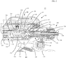
Fig. 2 is an enlarged, side, longitudinal, cross-sectional view of a proximal portion of the ultrasonic surgical instrument ofFig. 1 including an ultrasonic horn in accordance with the present disclosure coupling the transducer assembly with the waveguide; and -
Fig. 3 is a side, perspective view of the ultrasonic horn ofFig. 2 . - Referring to
Figs. 1 and2 , ultrasonicsurgical instrument 10 includes ahandle assembly 100 and anelongated assembly 200 extending distally fromhandle assembly 100.Handle assembly 100 includes ahousing 110 defining abody portion 112 and afixed handle portion 114.Handle assembly 100 further includes anactivation button 120 and aclamp trigger 130. -
Body portion 112 ofhousing 110 is configured to support an ultrasonic transducer and generator assembly ("TAG") 300 including agenerator 310 and anultrasonic transducer 320. TAG 300 may be permanently engaged withbody portion 112 ofhousing 110 or removable therefrom.Generator 310 includes ahousing 312 configured to house the internal electronics ofgenerator 310, and acradle 314 configured to rotatably supportultrasonic transducer 320. Alternatively,generator 310 may be remotely disposed and coupled to ultrasonicsurgical instrument 10 by way of a surgical cable. -
Ultrasonic transducer 320 includes apiezoelectric stack 322, ahorn 324, acasing 326, and abolt 328 securingpiezoelectric stack 322 betweenhorn 324 and a proximal nut (not shown). Horn 324 is described in greater detail below.Ultrasonic transducer 320 further includes a rotation knob 329 (Fig. 1 ).Casing 326 androtation knob 329 are engaged with one another and cooperate to form an enclosure to encapsulate the proximal nut,piezoelectric stack 322, and a portion ofhorn 324, with the remainder ofhorn 324 extending distally fromcasing 326.Rotation knob 329 is accessible from the exterior ofhandle assembly 100 and is configured for manual rotation to rotateultrasonic transducer 320 relative togenerator 310 andhousing 110. - A set of
connectors 330 and correspondingrotational contacts 334 associated withgenerator 310 andultrasonic transducer 320, respectively, enable drive signals to be communicated fromgenerator 310 topiezoelectric stack 322 ofultrasonic transducer 320 to driveultrasonic transducer 320 regardless of the rotational orientation ofultrasonic transducer 320. Horn 324, in turn, is configured to transmit the ultrasonic energy produced bypiezoelectric stack 322 towaveguide 230 ofelongated assembly 200 for transmission therealong toblade 282 ofend effector 280 ofelongated assembly 200, as detailed below. - Referring still to
Figs. 1 and2 ,fixed handle portion 114 ofhousing 110 defines acompartment 116 configured to receive abattery assembly 400 and adoor 118 configured to enclosecompartment 116. Anelectrical connection assembly 140 is disposed withinhousing 110 ofhandle assembly 100 and serves to electricallycouple activation button 120,generator 310 ofTAG 300, andbattery assembly 400 with one another when TAG 300 is supported on or inbody portion 112 ofhousing 110 andbattery assembly 400 is disposed withincompartment 116 offixed handle portion 114 ofhousing 110, thus enabling activation of ultrasonicsurgical instrument 10 in response to depression ofactivation button 120. In embodiments wheregenerator 310 is remote from ultrasonicsurgical instrument 10,battery assembly 400 and the configuration offixed handle portion 114 for receivingbattery assembly 400 need not be provided, asgenerator 310 may be powered by a standard wall outlet or other power source. - Elongated
assembly 200 of ultrasonicsurgical instrument 10 includes anouter drive sleeve 210, aninner support sleeve 220 disposed withinouter drive sleeve 210, awaveguide 230 extending throughinner support sleeve 220, adrive assembly 250, arotation knob 270, and anend effector 280 including ablade 282 and ajaw 284. A proximal portion ofouter drive sleeve 210 is operably coupled toclamp trigger 130 ofhandle assembly 100 viadrive assembly 250, while a distal portion ofouter drive sleeve 210 is operably coupled tojaw 284. As such,clamp trigger 130 is selectively actuatable to thereby moveouter drive sleeve 210 aboutinner support sleeve 220 topivot jaw 284 relative toblade 282 ofend effector 280 from a spaced-apart position to an approximated position for clamping tissue between jaw 284 andblade 282.Drive assembly 250 provides a force-limiting feature whereby the clamping pressure applied to tissue is limited to a particular clamping pressure or particular clamping pressure range.Rotation knob 270 is rotatable in either direction to rotateelongated assembly 200 in either direction relative to handleassembly 100. -
Waveguide 230, as noted above, extends throughinner support sleeve 220.Waveguide 230 defines abody 232 and ablade 282 extending from the distal end ofbody 232.Blade 282 serves as the blade ofend effector 280.Waveguide 230 further includes a proximal threadedmale connector 236 configured for threaded engagement within threadedfemale receiver 349 ofhorn 324 such that ultrasonic motion produced byultrasonic transducer 320 is transmitted alongwaveguide 230 toblade 282 for treating tissue clamping betweenblade 282 andjaw 284 or positioned adjacent toblade 282. - Turning now to
Figs. 2 and3 ,ultrasonic horn 324 is configured in such a manner thatultrasonic horn 324 may be formed via metal injection molding (MIM) instead of the traditional method of machining which is expensive due to the tight tolerance requirements of ultrasonic horns.Ultrasonic horn 324, more specifically, may be formed via MIM using zirconium-based amorphous metals, although other suitable metals are also contemplated. In order to enableultrasonic horn 324 to be formed via MIM, the volume and thickness ofultrasonic horn 324 must be below threshold levels to ensure the material can be injection molded and rapidly cooled within a mold. Specifically, it has been found that current manufacturing threshold levels for MIM of zirconium-based amorphous metals are: 80 g total mass, 0.6 mm to 4 mm wall thickness, and 100 mm total length. Thus, to ensure proper formation ofultrasonic horn 324 via MIM,ultrasonic horn 324 should define a total mass of less than about 80 g (wherein "about" accounts for manufacturing and material tolerances), a wall thickness of from about 0.6 mm to about 4 mm (wherein "about" accounts for manufacturing and material tolerances), and a total length of less than about 100 mm (wherein "about" accounts for manufacturing and material tolerances). - Ultrasonic horn 500 includes a body 510 and a nose 520 extending distally from body 510. Ultrasonic horn 500 defines a total length of less than about 100 mm. Body 510 defines a tubular configuration having a substantially uniform (within manufacturing and material tolerances) diameter along the entire length thereof. However, other configurations are also contemplated, e.g., cone-shaped. Body 510 defines a
hollow interior 346 and a wall thickness of the tubular wall surroundinghollow interior 346 of from about 0.6 mm to about 4 mm. Body 510 further defines a plurality ofslots 347 through the tubular wall thereof and extending intohollow interior 346. Body 510, more specifically, defines four equally-spacedelongated slots 347 having arched ends so as to define four equally-spaced, longitudinally-extending, and substantially parallel columns of body 510 that extend between the proximal end portion of body 510, which defines aproximal receiver 348 configured to receivebolt 328 to securepiezoelectric stack 322 betweenhorn 324 and the proximal nut (seeFig. 2 ), and a node point defined along body 510 towards a distal end of body 510. However, other suitable number and/or configuration ofslots 347 is also contemplated to define a corresponding configuration of body 510 extending between the proximal end portion thereof and the node point thereof towards the distal end of body 510.Slots 347, along withhollow interior 346, enable ultrasonic horn 500 to define a total mass of less than about 80 g and a wall thickness of from about 0.6 mm to about 4 mm. - Nose 520 of horn 500, as noted above, extends distally from body 510. Nose 520 tapers in proximal-to-distal direction along a portion of the length thereof and defines a threaded
female receiver 349 configured to receive proximal threadedmale connector 236 ofwaveguide 230 to permit releasable engagement ofwaveguide 230 withhorn 324. Nose 520, having a reduced diameter as compared with body 510, may be of solid construction (except for threaded female receiver 349) in embodiments where the diameter of nose 520 does not exceed 4 mm. Alternatively, nose 520 may define a hollow or partially-hollow configuration such that a wall thickness of any portion thereof does not exceed 4 mm. - While several embodiments of the disclosure have been detailed above and are shown in the drawings, it is not intended that the disclosure be limited thereto, as it is intended that the disclosure be as broad in scope as the art will allow and that the specification be read likewise. Therefore, the above description and accompanying drawings should not be construed as limiting, but merely as exemplifications of particular embodiments. Those skilled in the art will envision other modifications within the scope and spirit of the claims appended hereto.
- The invention may be described by reference to the following numbered paragraphs:-
- 1. An ultrasonic horn for an ultrasonic transducer assembly of an ultrasonic surgical instrument, comprising:
- a body defining a tubular configuration having a hollow interior, the body defining a plurality of slots therethrough and extending into the hollow interior; and
- a nose extending distally from the body,
- wherein the body defines a proximal connector configured to enable the body to be secured to a piezoelectric stack and the nose defines a distal connector configured to enable the nose to be engaged with a waveguide for transmission of ultrasonic energy produced by the piezoelectric stack to the waveguide.
- 2. The ultrasonic horn according to paragraph 1, wherein the body and the nose are monolithically formed as a single component from a zirconium-based amorphous metal.
- 3. The ultrasonic horn according to paragraph 1, wherein the ultrasonic horn defines a total mass of less than about 80 g.
- 4. The ultrasonic horn according to paragraph 1, wherein a thickness of each wall of the ultrasonic horn is between about 0.6 mm and about 4 mm.
- 5. The ultrasonic horn according to paragraph 1, wherein the ultrasonic horn defines a total length of less than about 100 mm.
- 6. The ultrasonic horn according to paragraph 1, wherein the plurality of slots are elongated slots equally-spaced about the body between a proximal end portion of the body and a node point defined towards a distal end of the body.
- 7. The ultrasonic horn according to paragraph 1, wherein the nose tapers in a proximal-to-distal direction.
- 8. The ultrasonic horn according to paragraph 1, wherein the nose is of solid construction except for the distal connector and defines a diameter between about 0.6 mm and about 4 mm.
- 9. An ultrasonic surgical instrument, comprising:
- a handle assembly including a housing and an ultrasonic transducer assembly supported by the housing, the ultrasonic transducer assembly including a piezoelectric stack and an ultrasonic horn secured to and extending distally from the piezoelectric stack, the ultrasonic horn including:
- a body defining a tubular configuration having a hollow interior, the body defining a plurality of slots therethrough and extending into the hollow interior; and
- a nose extending distally from the body; and
- an elongated assembly extending distally from the handle assembly, the elongated assembly including a waveguide configured to engage the nose of the ultrasonic horn, the waveguide defining a blade at a distal end thereof,
- wherein ultrasonic energy produced by the piezoelectric stack is transmitted along the horn and the waveguide to the blade for treating tissue adjacent the blade.
- a handle assembly including a housing and an ultrasonic transducer assembly supported by the housing, the ultrasonic transducer assembly including a piezoelectric stack and an ultrasonic horn secured to and extending distally from the piezoelectric stack, the ultrasonic horn including:
- 10. The ultrasonic surgical instrument according to paragraph 9, wherein the body and the nose are monolithically formed as a single component from a zirconium-based amorphous metal.
- 11. The ultrasonic surgical instrument according to paragraph 9, wherein the ultrasonic horn defines a total mass of less than about 80 g.
- 12. The ultrasonic surgical instrument according to paragraph 9, wherein a thickness of each wall of the ultrasonic horn is between about 0.6 mm and about 4 mm.
- 13. The ultrasonic surgical instrument according to paragraph 9, wherein the ultrasonic horn defines a total length of less than about 100 mm.
- 14. The ultrasonic surgical instrument according to paragraph 9, wherein the plurality of slots are elongated slots equally-spaced about the body between a proximal end portion of the body and a node point defined towards a distal end of the body.
- 15. The ultrasonic surgical instrument according to paragraph 9, wherein the nose tapers in a proximal-to-distal direction.
- 16. The ultrasonic surgical instrument according to paragraph 9, wherein the nose is of solid construction except for the distal connector and defines a diameter between about 0.6 mm and about 4 mm.
- 17. A method of manufacturing a transducer assembly for an ultrasonic surgical instrument, comprising:
- forming, via metal injection molding, an ultrasonic horn including a body and a nose extending distally from the body, the body defining a tubular configuration having a hollow interior, the body defining a plurality of slots therethrough and extending into the hollow interior; and
- securing a piezoelectric stack to a proximal end portion of the body of the ultrasonic horn.
- 18. The method according to paragraph 17, wherein the ultrasonic horn is formed from a zirconium-based amorphous metal.
- 19. The method according to paragraph 17, wherein the ultrasonic horn is formed to define a total mass of less than about 80 g and a thickness of each wall of the horn of between about 0.6 mm and about 4 mm.
- 20. The method according to paragraph 17, wherein securing the piezoelectric stack includes bolting the piezoelectric stack to the proximal end portion of the body of the ultrasonic horn.
Claims (15)
- An ultrasonic horn for an ultrasonic transducer assembly of an ultrasonic surgical instrument, comprising:a body defining a tubular configuration having a hollow interior, the body defining a plurality of slots therethrough and extending into the hollow interior; anda nose extending distally from the body,wherein the body defines a proximal connector configured to enable the body to be secured to a piezoelectric stack and the nose defines a distal connector configured to enable the nose to be engaged with a waveguide for transmission of ultrasonic energy produced by the piezoelectric stack to the waveguide.
- The ultrasonic horn according to claim 1, wherein the body and the nose are monolithically formed as a single component from a zirconium-based amorphous metal.
- The ultrasonic horn according to claim 1 or 2, wherein the ultrasonic horn defines a total mass of less than about 80 g.
- The ultrasonic horn according to claim 1, 2 or 3 wherein a thickness of each wall of the ultrasonic horn is between about 0.6 mm and about 4 mm.
- The ultrasonic horn according to any preceding claim, wherein the ultrasonic horn defines a total length of less than about 100 mm.
- The ultrasonic horn according to any preceding claim, wherein the plurality of slots are elongated slots equally-spaced about the body between a proximal end portion of the body and a node point defined towards a distal end of the body.
- The ultrasonic horn according to any preceding claim, wherein the nose tapers in a proximal-to-distal direction.
- The ultrasonic horn according to any preceding claim, wherein the nose is of solid construction except for the distal connector and defines a diameter between about 0.6 mm and about 4 mm.
- An ultrasonic surgical instrument, comprising:a handle assembly including a housing and an ultrasonic transducer assembly supported by the housing, the ultrasonic transducer assembly including a piezoelectric stack and an ultrasonic horn as claimed in any one of claims 1 to 8 secured to and extending distally from the piezoelectric stack,an elongated assembly extending distally from the handle assembly, the elongated assembly including a waveguide configured to engage the nose of the ultrasonic horn, the waveguide defining a blade at a distal end thereof,wherein ultrasonic energy produced by the piezoelectric stack is transmitted along the horn and the waveguide to the blade for treating tissue adjacent the blade.
- A method of manufacturing a transducer assembly for an ultrasonic surgical instrument, comprising:forming, via metal injection molding, an ultrasonic horn including a body and a nose extending distally from the body, the body defining a tubular configuration having a hollow interior, the body defining a plurality of slots therethrough and extending into the hollow interior; andsecuring a piezoelectric stack to a proximal end portion of the body of the ultrasonic horn.
- The method according to claim 10, wherein the ultrasonic horn is formed from a zirconium-based amorphous metal.
- The method according to claim 10 or 11, wherein the ultrasonic horn is formed to define a total mass of less than about 80 g and a thickness of each wall of the horn of between about 0.6 mm and about 4 mm.
- The method according to claim 10, 11 or 12, wherein securing the piezoelectric stack includes bolting the piezoelectric stack to the proximal end portion of the body of the ultrasonic horn.
- The method according to any one of claims 10 to 13 wherein the nose os formed to taper in a proximal-to-distal direction.
- The method according to any one of claims 10 to 14 wherein the nose is formed as a solid construction, except for the distal connector, having a diameter between 0.6mm and 4mm.
Applications Claiming Priority (1)
| Application Number | Priority Date | Filing Date | Title |
|---|---|---|---|
| US15/882,079 US11259832B2 (en) | 2018-01-29 | 2018-01-29 | Ultrasonic horn for an ultrasonic surgical instrument, ultrasonic surgical instrument including the same, and method of manufacturing an ultrasonic horn |
Publications (1)
| Publication Number | Publication Date |
|---|---|
| EP3517060A1 true EP3517060A1 (en) | 2019-07-31 |
Family
ID=65236953
Family Applications (1)
| Application Number | Title | Priority Date | Filing Date |
|---|---|---|---|
| EP19153890.9A Pending EP3517060A1 (en) | 2018-01-29 | 2019-01-28 | Ultrasonic horn for an ultrasonic surgical instrument, ultrasonic surgical instrument including the same, and method of manufacturing an ultrasonic horn |
Country Status (3)
| Country | Link |
|---|---|
| US (1) | US11259832B2 (en) |
| EP (1) | EP3517060A1 (en) |
| CN (1) | CN110090067B (en) |
Families Citing this family (1)
| Publication number | Priority date | Publication date | Assignee | Title |
|---|---|---|---|---|
| WO2023076479A1 (en) * | 2021-10-27 | 2023-05-04 | Suono Bio, Inc. | Ultrasound-mediated drug delivery |
Citations (7)
| Publication number | Priority date | Publication date | Assignee | Title |
|---|---|---|---|---|
| US20020055754A1 (en) * | 1999-10-05 | 2002-05-09 | Kevin Ranucci | Utrasonic probe device with rapid attachment and detachment means |
| EP1990032A1 (en) * | 2007-05-10 | 2008-11-12 | Alcon, Inc. | Method of operating an ultrasound handpiece |
| WO2010049684A1 (en) * | 2008-10-27 | 2010-05-06 | Sra Developments Limited | Torsional mode ultrasonic generator |
| US20100324581A1 (en) * | 2006-12-08 | 2010-12-23 | Alcon, Inc. | Torsional Ultrasound Hand Piece That Eliminates Chatter |
| US8043229B2 (en) * | 2007-06-29 | 2011-10-25 | Actuated Medical, Inc. | Medical tool for reduced penetration force |
| WO2015041849A2 (en) * | 2013-09-20 | 2015-03-26 | Ethicon Endo-Surgery, Inc. | Transducer features for ultrasonic surgical instrument |
| US20170296216A1 (en) * | 2012-11-06 | 2017-10-19 | Med-Sonics Corporation | Systems and methods for controlling delivery of ultrasonic energy to a bodily tissue |
Family Cites Families (178)
| Publication number | Priority date | Publication date | Assignee | Title |
|---|---|---|---|---|
| US1813902A (en) | 1928-01-18 | 1931-07-14 | Liebel Flarsheim Co | Electrosurgical apparatus |
| US2235274A (en) | 1938-10-13 | 1941-03-18 | Trehern Joseph Thomas | Grounding clamp |
| US2874470A (en) | 1954-05-28 | 1959-02-24 | James R Richards | High frequency dental tool |
| NL106732C (en) | 1955-03-08 | |||
| US3293456A (en) | 1963-03-18 | 1966-12-20 | Branson Instr | Ultrasonic cleaning apparatus |
| US3432691A (en) | 1966-09-15 | 1969-03-11 | Branson Instr | Oscillatory circuit for electro-acoustic converter |
| US3489930A (en) | 1968-07-29 | 1970-01-13 | Branson Instr | Apparatus for controlling the power supplied to an ultrasonic transducer |
| US3629726A (en) | 1969-08-29 | 1971-12-21 | Surgical Design Corp | Oscillator and oscillator control circuit |
| US3668486A (en) | 1971-01-08 | 1972-06-06 | Crest Ultrasonics Corp | Load-sensitive generator for driving piezo-electric transducers |
| US3924335A (en) | 1971-02-26 | 1975-12-09 | Ultrasonic Systems | Ultrasonic dental and other instrument means and methods |
| US3809977A (en) | 1971-02-26 | 1974-05-07 | Ultrasonic Systems | Ultrasonic kits and motor systems |
| US3875945A (en) | 1973-11-02 | 1975-04-08 | Demetron Corp | Electrosurgery instrument |
| US4012647A (en) | 1974-01-31 | 1977-03-15 | Ultrasonic Systems, Inc. | Ultrasonic motors and converters |
| US4227110A (en) | 1976-11-10 | 1980-10-07 | Westinghouse Electric Corp. | Transducer control system |
| US4300083A (en) | 1977-07-05 | 1981-11-10 | Automation Devices, Inc. | Constant amplitude controller and method |
| US4193818A (en) | 1978-05-05 | 1980-03-18 | American Sterilizer Company | Combined ultrasonic cleaning and biocidal treatment in a single pressure vessel |
| JPS5590195A (en) | 1978-12-28 | 1980-07-08 | Ootake Seisakusho:Kk | Ultrasonic oscillator with output meter |
| US4370302A (en) | 1980-01-04 | 1983-01-25 | Teijin Limited | Machine for solid phase polymerization |
| US4641053A (en) | 1984-08-14 | 1987-02-03 | Matsushita Seiko Co., Ltd. | Ultrasonic liquid atomizer with an improved soft start circuit |
| US5113116A (en) | 1989-10-05 | 1992-05-12 | Firma J. Eberspacher | Circuit arrangement for accurately and effectively driving an ultrasonic transducer |
| US5224680A (en) | 1991-08-22 | 1993-07-06 | Automated Medical Products Corp. | Surgical instrument holder |
| US5394187A (en) | 1992-06-26 | 1995-02-28 | Apollo Camera, L.L.C. | Video imaging systems and method using a single interline progressive scanning sensor and sequential color object illumination |
| US5408268A (en) | 1992-06-26 | 1995-04-18 | Apollo Camera, L.L.C. | Video imaging system and method using a single full frame sensor and sequential color object illumination |
| US6449006B1 (en) | 1992-06-26 | 2002-09-10 | Apollo Camera, Llc | LED illumination system for endoscopic cameras |
| US5264925A (en) | 1992-06-26 | 1993-11-23 | Life Surgery, Inc. | Single sensor video imaging system and method using sequential color object illumination |
| US5374813A (en) | 1992-10-15 | 1994-12-20 | Life Surgery, Inc. | Surgical instrument recycling and tracking system |
| US5275166A (en) | 1992-11-16 | 1994-01-04 | Ethicon, Inc. | Method and apparatus for performing ultrasonic assisted surgical procedures |
| US5582617A (en) | 1993-07-21 | 1996-12-10 | Charles H. Klieman | Surgical instrument for endoscopic and general surgery |
| US5858018A (en) | 1993-08-25 | 1999-01-12 | Apollo Camera, Llc | Low profile tool for applying spring action ligation clips |
| CA2147757A1 (en) | 1993-08-25 | 1995-03-02 | John I. Shipp | Surgical ligation clip |
| US5490860A (en) | 1993-12-08 | 1996-02-13 | Sofamor Danek Properties, Inc. | Portable power cutting tool |
| DE4401314C2 (en) | 1994-01-19 | 1998-01-22 | Nbb Nachrichtentech Gmbh | Multi-step switch |
| DE4419431C1 (en) | 1994-06-03 | 1995-04-27 | Goldschmidt Ag Th | Polyolefins, polyolefin blends and elastomer-modified polyolefins having increased surface polarity, process for their preparation, and their use |
| US5779130A (en) | 1994-08-05 | 1998-07-14 | United States Surgical Corporation | Self-contained powered surgical apparatus |
| US5451220A (en) | 1994-08-15 | 1995-09-19 | Microsonic Engineering Devices Company, Inc. | Battery operated multifunction ultrasonic wire for angioplasty |
| JP3487981B2 (en) | 1994-10-20 | 2004-01-19 | オリンパス株式会社 | Ultrasonic probe |
| US5717306A (en) | 1994-11-18 | 1998-02-10 | Shipp; John I. | Battery identification and power interrupt system |
| US6284185B1 (en) | 1995-04-28 | 2001-09-04 | Nippon Kayaku Kabushiki Kaisha | Ultraviolet-curable adhesive composition for bonding opaque substrates |
| US5792138A (en) | 1996-02-22 | 1998-08-11 | Apollo Camera, Llc | Cordless bipolar electrocautery unit with automatic power control |
| US5728130A (en) | 1996-03-22 | 1998-03-17 | Olympus Optical Co., Ltd. | Ultrasonic trocar system |
| US6031526A (en) | 1996-08-08 | 2000-02-29 | Apollo Camera, Llc | Voice controlled medical text and image reporting system |
| GB9617749D0 (en) | 1996-08-23 | 1996-10-02 | Young Michael J R | Improved apparatus for ultrasonic therapeutic trteatment |
| CA2213948C (en) | 1996-09-19 | 2006-06-06 | United States Surgical Corporation | Ultrasonic dissector |
| DE69727183T2 (en) | 1996-09-24 | 2004-11-04 | Xomed Surgical Products, Inc., North Jacksonville | Driven handpiece |
| US6036667A (en) | 1996-10-04 | 2000-03-14 | United States Surgical Corporation | Ultrasonic dissection and coagulation system |
| US6126676A (en) | 1996-10-30 | 2000-10-03 | Ethicon, Inc. | Surgical tipping apparatus |
| US5776155A (en) | 1996-12-23 | 1998-07-07 | Ethicon Endo-Surgery, Inc. | Methods and devices for attaching and detaching transmission components |
| US6067988A (en) | 1996-12-26 | 2000-05-30 | Eclipse Surgical Technologies, Inc. | Method for creation of drug delivery and/or stimulation pockets in myocardium |
| US5944737A (en) | 1997-10-10 | 1999-08-31 | Ethicon Endo-Surgery, Inc. | Ultrasonic clamp coagulator apparatus having improved waveguide support member |
| US5810859A (en) | 1997-02-28 | 1998-09-22 | Ethicon Endo-Surgery, Inc. | Apparatus for applying torque to an ultrasonic transmission component |
| PT1011494E (en) | 1997-03-05 | 2007-04-30 | Univ Columbia | Electrothermal device for sealing and joining or cutting tissue |
| US5897569A (en) | 1997-04-16 | 1999-04-27 | Ethicon Endo-Surgery, Inc. | Ultrasonic generator with supervisory control circuitry |
| JP3816960B2 (en) | 1997-05-15 | 2006-08-30 | 松下電工株式会社 | Ultrasonic equipment |
| US5938633A (en) | 1997-07-09 | 1999-08-17 | Ethicon Endo-Surgery, Inc. | Ultrasonic surgical devices |
| US5954746A (en) | 1997-10-09 | 1999-09-21 | Ethicon Endo-Surgery, Inc. | Dual cam trigger for a surgical instrument |
| US5947984A (en) | 1997-10-10 | 1999-09-07 | Ethicon Endo-Surger, Inc. | Ultrasonic clamp coagulator apparatus having force limiting clamping mechanism |
| US5954736A (en) | 1997-10-10 | 1999-09-21 | Ethicon Endo-Surgery, Inc. | Coagulator apparatus having indexed rotational positioning |
| US5873873A (en) | 1997-10-10 | 1999-02-23 | Ethicon Endo-Surgery, Inc. | Ultrasonic clamp coagulator apparatus having improved clamp mechanism |
| US6068647A (en) | 1997-10-10 | 2000-05-30 | Ethicon Endo-Surgery, Inc. | Ultrasonic clamp coagulator apparatus having improved clamp arm tissue pad |
| US6589200B1 (en) | 1999-02-22 | 2003-07-08 | Ethicon Endo-Surgery, Inc. | Articulating ultrasonic surgical shears |
| US6454782B1 (en) | 1998-04-13 | 2002-09-24 | Ethicon Endo-Surgery, Inc. | Actuation mechanism for surgical instruments |
| GB2337118A (en) | 1998-05-06 | 1999-11-10 | Csi Technology Inc | Interchangeable sensor monitoring device |
| US5994855A (en) | 1998-05-07 | 1999-11-30 | Optiva Corporation | Automatic power adjustment system for introductory use of a vibrating device on a human body |
| US6162194A (en) | 1998-05-20 | 2000-12-19 | Apollo Camera, Llc | Surgical irrigation apparatus and methods for use |
| US6083228A (en) | 1998-06-09 | 2000-07-04 | Michelson; Gary K. | Device and method for preparing a space between adjacent vertebrae to receive an insert |
| US6660017B2 (en) | 1998-06-29 | 2003-12-09 | Ethicon Endo-Surgery, Inc. | Balanced ultrasonic blade including a singular balance asymmetry |
| CA2276313C (en) | 1998-06-29 | 2008-01-29 | Ethicon Endo-Surgery, Inc. | Balanced ultrasonic blade including a plurality of balance asymmetries |
| CA2276316C (en) | 1998-06-29 | 2008-02-12 | Ethicon Endo-Surgery, Inc. | Method of balancing asymmetric ultrasonic surgical blades |
| US6309400B2 (en) | 1998-06-29 | 2001-10-30 | Ethicon Endo-Surgery, Inc. | Curved ultrasonic blade having a trapezoidal cross section |
| US6095981A (en) | 1998-07-01 | 2000-08-01 | The Regents Of The University Of California | Apparatus for attachment of needle or catheter to endoluminal ultrasound probe |
| US6350269B1 (en) | 1999-03-01 | 2002-02-26 | Apollo Camera, L.L.C. | Ligation clip and clip applier |
| US6290575B1 (en) | 1999-03-01 | 2001-09-18 | John I. Shipp | Surgical ligation clip with increased ligating force |
| US6666875B1 (en) | 1999-03-05 | 2003-12-23 | Olympus Optical Co., Ltd. | Surgical apparatus permitting recharge of battery-driven surgical instrument in noncontact state |
| US6287344B1 (en) | 1999-03-31 | 2001-09-11 | Ethicon Endo-Surgery, Inc. | Method for repairing tissue defects using an ultrasonic device |
| US6416486B1 (en) | 1999-03-31 | 2002-07-09 | Ethicon Endo-Surgery, Inc. | Ultrasonic surgical device having an embedding surface and a coagulating surface |
| US6257241B1 (en) | 1999-03-31 | 2001-07-10 | Ethicon Endo-Surgery, Inc. | Method for repairing tissue defects using ultrasonic radio frequency energy |
| AU774545B2 (en) | 1999-04-15 | 2004-07-01 | Ethicon Endo-Surgery, Inc. | Ultrasonic transducer with improved compressive loading |
| US6278218B1 (en) | 1999-04-15 | 2001-08-21 | Ethicon Endo-Surgery, Inc. | Apparatus and method for tuning ultrasonic transducers |
| US6454781B1 (en) | 1999-05-26 | 2002-09-24 | Ethicon Endo-Surgery, Inc. | Feedback control in an ultrasonic surgical instrument for improved tissue effects |
| US6214023B1 (en) | 1999-06-21 | 2001-04-10 | Ethicon Endo-Surgery, Inc. | Ultrasonic surgical instrument with removable clamp arm |
| US6254623B1 (en) | 1999-06-30 | 2001-07-03 | Ethicon Endo-Surgery, Inc. | Ultrasonic clamp coagulator surgical instrument with improved blade geometry |
| JP4282180B2 (en) | 1999-10-15 | 2009-06-17 | オリンパス株式会社 | Water suction device and medical operation system |
| US6458142B1 (en) | 1999-10-05 | 2002-10-01 | Ethicon Endo-Surgery, Inc. | Force limiting mechanism for an ultrasonic surgical instrument |
| US6325811B1 (en) | 1999-10-05 | 2001-12-04 | Ethicon Endo-Surgery, Inc. | Blades with functional balance asymmetries for use with ultrasonic surgical instruments |
| JP4233742B2 (en) | 1999-10-05 | 2009-03-04 | エシコン・エンド−サージェリィ・インコーポレイテッド | Connecting curved clamp arms and tissue pads used with ultrasonic surgical instruments |
| US6432118B1 (en) | 1999-10-05 | 2002-08-13 | Ethicon Endo-Surgery, Inc. | Multifunctional curved blade for use with an ultrasonic surgical instrument |
| US6352532B1 (en) | 1999-12-14 | 2002-03-05 | Ethicon Endo-Surgery, Inc. | Active load control of ultrasonic surgical instruments |
| US6423082B1 (en) | 2000-03-31 | 2002-07-23 | Ethicon Endo-Surgery, Inc. | Ultrasonic surgical blade with improved cutting and coagulation features |
| CN2420088Y (en) | 2000-05-15 | 2001-02-21 | 铨宝工业股份有限公司 | Electric drill base casing structure with cladding clamp |
| US6558376B2 (en) | 2000-06-30 | 2003-05-06 | Gregory D. Bishop | Method of use of an ultrasonic clamp and coagulation apparatus with tissue support surface |
| US20020091339A1 (en) | 2000-08-24 | 2002-07-11 | Timi 3 Systems, Inc. | Systems and methods for applying ultrasound energy to stimulating circulatory activity in a targeted body region of an individual |
| US6679899B2 (en) | 2000-10-20 | 2004-01-20 | Ethicon Endo-Surgery, Inc. | Method for detecting transverse vibrations in an ultrasonic hand piece |
| US6623500B1 (en) | 2000-10-20 | 2003-09-23 | Ethicon Endo-Surgery, Inc. | Ring contact for rotatable connection of switch assembly for use in a surgical system |
| US7273483B2 (en) | 2000-10-20 | 2007-09-25 | Ethicon Endo-Surgery, Inc. | Apparatus and method for alerting generator functions in an ultrasonic surgical system |
| US6678621B2 (en) | 2000-10-20 | 2004-01-13 | Ethicon Endo-Surgery, Inc. | Output displacement control using phase margin in an ultrasonic surgical hand piece |
| US6633234B2 (en) | 2000-10-20 | 2003-10-14 | Ethicon Endo-Surgery, Inc. | Method for detecting blade breakage using rate and/or impedance information |
| US6662127B2 (en) | 2000-10-20 | 2003-12-09 | Ethicon Endo-Surgery, Inc. | Method for detecting presence of a blade in an ultrasonic system |
| US6945981B2 (en) | 2000-10-20 | 2005-09-20 | Ethicon-Endo Surgery, Inc. | Finger operated switch for controlling a surgical handpiece |
| US6626926B2 (en) | 2000-10-20 | 2003-09-30 | Ethicon Endo-Surgery, Inc. | Method for driving an ultrasonic system to improve acquisition of blade resonance frequency at startup |
| US6537291B2 (en) | 2000-10-20 | 2003-03-25 | Ethicon Endo-Surgery, Inc. | Method for detecting a loose blade in a hand piece connected to an ultrasonic surgical system |
| US6908472B2 (en) | 2000-10-20 | 2005-06-21 | Ethicon Endo-Surgery, Inc. | Apparatus and method for altering generator functions in an ultrasonic surgical system |
| US6480796B2 (en) | 2000-10-20 | 2002-11-12 | Ethicon Endo-Surgery, Inc. | Method for improving the start up of an ultrasonic system under zero load conditions |
| US6500188B2 (en) | 2001-01-29 | 2002-12-31 | Ethicon Endo-Surgery, Inc. | Ultrasonic surgical instrument with finger actuator |
| US6752815B2 (en) | 2001-01-31 | 2004-06-22 | Ethicon Endo-Surgery, Inc. | Method and waveguides for changing the direction of longitudinal vibrations |
| US6561983B2 (en) | 2001-01-31 | 2003-05-13 | Ethicon Endo-Surgery, Inc. | Attachments of components of ultrasonic blades or waveguides |
| US6719776B2 (en) | 2001-03-01 | 2004-04-13 | Ethicon Endo-Surgery, Inc. | Thumb pad actuator for an ultrasonic surgical instrument |
| US6514267B2 (en) | 2001-03-26 | 2003-02-04 | Iep Pharmaceutical Devices Inc. | Ultrasonic scalpel |
| US20020151837A1 (en) | 2001-04-16 | 2002-10-17 | Surgicon Inc. | Surgical irrigation apparatus and methods for use |
| US6588277B2 (en) | 2001-05-21 | 2003-07-08 | Ethicon Endo-Surgery | Method for detecting transverse mode vibrations in an ultrasonic hand piece/blade |
| US7796969B2 (en) | 2001-10-10 | 2010-09-14 | Peregrine Semiconductor Corporation | Symmetrically and asymmetrically stacked transistor group RF switch |
| US20030144680A1 (en) | 2002-01-22 | 2003-07-31 | Sontra Medical, Inc. | Portable ultrasonic scalpel/cautery device |
| JP4088665B2 (en) | 2002-01-23 | 2008-05-21 | 株式会社Ijr | Ultrasonic wave generation method and apparatus |
| US7501198B2 (en) | 2002-02-07 | 2009-03-10 | Linvatec Corporation | Sterile transfer battery container |
| JP2003305050A (en) | 2002-04-17 | 2003-10-28 | Olympus Optical Co Ltd | Ultrasonic operation apparatus |
| JP2004129871A (en) | 2002-10-10 | 2004-04-30 | Olympus Corp | Ultrasonic operating device |
| US7678125B2 (en) | 2002-11-12 | 2010-03-16 | Apollo Camera, L.L.C. | Surgical ligation clip |
| US7217128B2 (en) | 2002-12-12 | 2007-05-15 | Discus Dental Impressions, Inc. | Ultrasonic dental insert having interchangeable plastic and metal tips |
| US7883031B2 (en) | 2003-05-20 | 2011-02-08 | James F. Collins, Jr. | Ophthalmic drug delivery system |
| US8172870B2 (en) | 2003-06-09 | 2012-05-08 | Microline Surgical, Inc. | Ligation clip applier |
| US7037306B2 (en) | 2003-06-30 | 2006-05-02 | Ethicon, Inc. | System for creating linear lesions for the treatment of atrial fibrillation |
| US7066895B2 (en) | 2003-06-30 | 2006-06-27 | Ethicon, Inc. | Ultrasonic radial focused transducer for pulmonary vein ablation |
| US7074218B2 (en) | 2003-06-30 | 2006-07-11 | Ethicon, Inc. | Multi-modality ablation device |
| US7128720B2 (en) | 2003-06-30 | 2006-10-31 | Ethicon, Inc. | Ultrasonic finger probe |
| US6915623B2 (en) | 2003-08-14 | 2005-07-12 | Ethicon, Inc. | Method for assembling a package for sutures |
| US7572266B2 (en) | 2003-10-21 | 2009-08-11 | Young Wayne P | Clip applier tool having a discharge configuration |
| AU2004286865B2 (en) | 2003-11-04 | 2008-07-24 | University Of Washington | Toothbrush employing an acoustic waveguide |
| US7163548B2 (en) | 2003-11-05 | 2007-01-16 | Ethicon Endo-Surgery, Inc | Ultrasonic surgical blade and instrument having a gain step |
| WO2005051838A2 (en) | 2003-11-19 | 2005-06-09 | Transoma Medical, Inc. | Feedback control of ventricular assist devices |
| US7879033B2 (en) | 2003-11-20 | 2011-02-01 | Covidien Ag | Electrosurgical pencil with advanced ES controls |
| US7118564B2 (en) | 2003-11-26 | 2006-10-10 | Ethicon Endo-Surgery, Inc. | Medical treatment system with energy delivery device for limiting reuse |
| TWI238715B (en) | 2004-02-06 | 2005-09-01 | Shr Ji Tau | Medicament dispensing and injecting system with radiation protection |
| US20050234484A1 (en) | 2004-02-27 | 2005-10-20 | Houser Kevin L | Ultrasonic surgical blade having transverse and longitudinal vibration |
| US7179254B2 (en) | 2004-03-09 | 2007-02-20 | Ethicon, Inc. | High intensity ablation device |
| US7645256B2 (en) * | 2004-08-12 | 2010-01-12 | Alcon, Inc. | Ultrasound handpiece |
| JP4282523B2 (en) | 2004-03-30 | 2009-06-24 | オリンパス株式会社 | Ultrasonic treatment device |
| JP4602681B2 (en) | 2004-03-30 | 2010-12-22 | オリンパス株式会社 | Ultrasonic coagulation / cutting device and method for assembling and disassembling this device |
| JP2005296411A (en) | 2004-04-13 | 2005-10-27 | Olympus Corp | Ultrasonic treatment apparatus |
| JP4917019B2 (en) | 2004-05-04 | 2012-04-18 | オーツー マイクロ, インコーポレーテッド | Cordless power tool with protected weak link element |
| JP4300169B2 (en) | 2004-09-10 | 2009-07-22 | アロカ株式会社 | Ultrasound surgical device |
| CN101432089B (en) | 2004-09-27 | 2010-12-01 | 布莱克和戴克公司 | Tool chuck with sleeve and clutch mechanism to remove operator variability |
| MX2007004151A (en) | 2004-10-08 | 2007-09-11 | Johnson & Johnson | Ultrasonic surgical instrument. |
| EP1805863B1 (en) | 2004-10-18 | 2013-06-26 | Black & Decker, Inc. | Cordless power system |
| US7807299B2 (en) | 2004-10-29 | 2010-10-05 | Medtronic, Inc. | Lithium-ion battery |
| CA2588932C (en) | 2004-11-30 | 2016-09-27 | John T. Haynes | Determining respiratory or circulatory health condition in animals for improved management |
| JP2006228567A (en) | 2005-02-17 | 2006-08-31 | Olympus Medical Systems Corp | Portable electronic device and capsule type endoscope diagnostic system |
| US20060206100A1 (en) | 2005-03-09 | 2006-09-14 | Brasseler Usa Medical Llc | Surgical apparatus and power module for same, and a method of preparing a surgical apparatus |
| US20060217729A1 (en) | 2005-03-09 | 2006-09-28 | Brasseler Usa Medical Llc | Surgical apparatus and tools for same |
| US7335997B2 (en) | 2005-03-31 | 2008-02-26 | Ethicon Endo-Surgery, Inc. | System for controlling ultrasonic clamping and cutting instruments |
| NZ563822A (en) | 2005-05-03 | 2011-01-28 | Ultreo Inc | Oral hygiene devices employing an acoustic waveguide |
| US8573462B2 (en) | 2006-05-19 | 2013-11-05 | Ethicon Endo-Surgery, Inc. | Electrical surgical instrument with optimized power supply and drive |
| US7230199B2 (en) | 2005-08-19 | 2007-06-12 | Zippy Technology Corp. | Multi-stage button switch |
| US20070191713A1 (en) | 2005-10-14 | 2007-08-16 | Eichmann Stephen E | Ultrasonic device for cutting and coagulating |
| US20070149881A1 (en) | 2005-12-22 | 2007-06-28 | Rabin Barry H | Ultrasonically Powered Medical Devices and Systems, and Methods and Uses Thereof |
| JP4370302B2 (en) | 2006-01-13 | 2009-11-25 | オリンパスメディカルシステムズ株式会社 | Press operation type two-stage switch device and endoscope to which the same is applied |
| US20070166663A1 (en) | 2006-01-18 | 2007-07-19 | Telles Heidi A | Cordless ultrasonic dental scaler |
| US7464846B2 (en) | 2006-01-31 | 2008-12-16 | Ethicon Endo-Surgery, Inc. | Surgical instrument having a removable battery |
| US20070239101A1 (en) | 2006-02-21 | 2007-10-11 | David Kellogg | Method for applying serum to a person's skin |
| US9675375B2 (en) | 2006-03-29 | 2017-06-13 | Ethicon Llc | Ultrasonic surgical system and method |
| US7897888B2 (en) | 2006-03-30 | 2011-03-01 | Strattec Security Corporation | Key fob device and method |
| US8114104B2 (en) | 2006-06-01 | 2012-02-14 | Ethicon Endo-Surgery, Inc. | Mechanism for assembly of ultrasonic instrument |
| AU2007286660A1 (en) | 2006-08-25 | 2008-02-28 | Eilaz Babaev | Portable ultrasound device for the treatment of wounds |
| US7217893B1 (en) | 2006-10-13 | 2007-05-15 | Altek Corporation | Two-stage button structure |
| US20080172076A1 (en) * | 2006-11-01 | 2008-07-17 | Alcon, Inc. | Ultrasound apparatus and method of use |
| JP4104648B1 (en) | 2007-09-13 | 2008-06-18 | 和征 榊原 | Battery pack |
| US8758342B2 (en) | 2007-11-28 | 2014-06-24 | Covidien Ag | Cordless power-assisted medical cauterization and cutting device |
| US8425545B2 (en) | 2007-12-03 | 2013-04-23 | Covidien Ag | Cordless hand-held ultrasonic cautery cutting device and method |
| US20090143800A1 (en) | 2007-12-03 | 2009-06-04 | Derek Dee Deville | Cordless Hand-Held Ultrasonic Cautery Cutting Device |
| US9107690B2 (en) | 2007-12-03 | 2015-08-18 | Covidien Ag | Battery-powered hand-held ultrasonic surgical cautery cutting device |
| US7977587B2 (en) | 2008-10-08 | 2011-07-12 | Research In Motion Limited | Two-stage switch assembly |
| CN101632849A (en) * | 2009-07-14 | 2010-01-27 | 张毓笠 | Ultrasonic debridement surgical system |
| CA2774751C (en) | 2011-04-15 | 2018-11-06 | Covidien Ag | Battery powered hand-held ultrasonic surgical cautery cutting device |
| US9241732B2 (en) | 2012-10-16 | 2016-01-26 | Covdien LP | Surgical instrument |
| US10368892B2 (en) | 2013-11-22 | 2019-08-06 | Ethicon Llc | Features for coupling surgical instrument shaft assembly with instrument body |
| US10010340B2 (en) | 2014-02-28 | 2018-07-03 | Ethicon Llc | Ultrasonic surgical instrument with removable handle assembly |
| GB201411381D0 (en) * | 2014-06-26 | 2014-08-13 | Sra Dev Ltd | Torsional revision tool |
| CN104434231B (en) * | 2014-11-27 | 2016-08-17 | 大连理工大学 | A kind of PZT transducer and ultrasonic transformer integrative ultrasonic drive structure |
| US9763689B2 (en) * | 2015-05-12 | 2017-09-19 | Tenex Health, Inc. | Elongated needles for ultrasonic applications |
| US10779847B2 (en) * | 2016-08-25 | 2020-09-22 | Ethicon Llc | Ultrasonic transducer to waveguide joining |
-
2018
- 2018-01-29 US US15/882,079 patent/US11259832B2/en active Active
-
2019
- 2019-01-28 EP EP19153890.9A patent/EP3517060A1/en active Pending
- 2019-01-29 CN CN201910088623.1A patent/CN110090067B/en active Active
Patent Citations (7)
| Publication number | Priority date | Publication date | Assignee | Title |
|---|---|---|---|---|
| US20020055754A1 (en) * | 1999-10-05 | 2002-05-09 | Kevin Ranucci | Utrasonic probe device with rapid attachment and detachment means |
| US20100324581A1 (en) * | 2006-12-08 | 2010-12-23 | Alcon, Inc. | Torsional Ultrasound Hand Piece That Eliminates Chatter |
| EP1990032A1 (en) * | 2007-05-10 | 2008-11-12 | Alcon, Inc. | Method of operating an ultrasound handpiece |
| US8043229B2 (en) * | 2007-06-29 | 2011-10-25 | Actuated Medical, Inc. | Medical tool for reduced penetration force |
| WO2010049684A1 (en) * | 2008-10-27 | 2010-05-06 | Sra Developments Limited | Torsional mode ultrasonic generator |
| US20170296216A1 (en) * | 2012-11-06 | 2017-10-19 | Med-Sonics Corporation | Systems and methods for controlling delivery of ultrasonic energy to a bodily tissue |
| WO2015041849A2 (en) * | 2013-09-20 | 2015-03-26 | Ethicon Endo-Surgery, Inc. | Transducer features for ultrasonic surgical instrument |
Also Published As
| Publication number | Publication date |
|---|---|
| CN110090067B (en) | 2022-07-05 |
| US11259832B2 (en) | 2022-03-01 |
| US20190231384A1 (en) | 2019-08-01 |
| CN110090067A (en) | 2019-08-06 |
Similar Documents
| Publication | Publication Date | Title |
|---|---|---|
| US10582944B2 (en) | Ultrasonic surgical instrument with torque assist feature | |
| US11627981B2 (en) | Ultrasonic transducer assembly and ultrasonic surgical instrument incorporating the same | |
| US20220117621A1 (en) | Compact ultrasonic transducer and ultrasonic surgical instrument including the same | |
| EP3520721A1 (en) | Utrasonic horn, ultrasonic transducer assembly, and ultrasonic surgical instrument including the same | |
| EP3517060A1 (en) | Ultrasonic horn for an ultrasonic surgical instrument, ultrasonic surgical instrument including the same, and method of manufacturing an ultrasonic horn | |
| US20210052293A1 (en) | Hemostat-style ultrasonic surgical instrument with clamp force-limiting feature | |
| CN210185655U (en) | Compact ultrasonic transducer and ultrasonic surgical instrument | |
| EP3996609A1 (en) | Ultrasonic transducer assembly and ultrasonic surgical instrument incorporating the same | |
| US20210369295A1 (en) | Ultrasonic transducer casing, ultrasonic transducer assembly, and ultrasonic surgical instrument | |
| US20220192696A1 (en) | Ultrasonic waveguide and blade for ultrasonic surgical instruments and method of manufacturing the same | |
| US20210267623A1 (en) | Ultrasonic transducer assembly for a surgical instrument and method of assembling the same | |
| US20200268407A1 (en) | Ultrasonic surgical instrument incorporating contactless transfer of drive and data signals | |
| US20210361316A1 (en) | Ultrasonic transducer assembly for an ultrasonic surgical instrument | |
| US20230121477A1 (en) | Systems and methods for operating a surgical device | |
| CN115605147A (en) | Articulating ultrasonic surgical instrument and system |
Legal Events
| Date | Code | Title | Description |
|---|---|---|---|
| PUAI | Public reference made under article 153(3) epc to a published international application that has entered the european phase |
Free format text: ORIGINAL CODE: 0009012 |
|
| STAA | Information on the status of an ep patent application or granted ep patent |
Free format text: STATUS: REQUEST FOR EXAMINATION WAS MADE |
|
| 17P | Request for examination filed |
Effective date: 20190128 |
|
| AK | Designated contracting states |
Kind code of ref document: A1 Designated state(s): AL AT BE BG CH CY CZ DE DK EE ES FI FR GB GR HR HU IE IS IT LI LT LU LV MC MK MT NL NO PL PT RO RS SE SI SK SM TR |
|
| AX | Request for extension of the european patent |
Extension state: BA ME |
|
| RBV | Designated contracting states (corrected) |
Designated state(s): AL AT BE BG CH CY CZ DE DK EE ES FI FR GB GR HR HU IE IS IT LI LT LU LV MC MK MT NL NO PL PT RO RS SE SI SK SM TR |