EP3516925B1 - Infrarotflächenstrahler - Google Patents
Infrarotflächenstrahler Download PDFInfo
- Publication number
- EP3516925B1 EP3516925B1 EP17755502.6A EP17755502A EP3516925B1 EP 3516925 B1 EP3516925 B1 EP 3516925B1 EP 17755502 A EP17755502 A EP 17755502A EP 3516925 B1 EP3516925 B1 EP 3516925B1
- Authority
- EP
- European Patent Office
- Prior art keywords
- conductor track
- conductor
- carrier
- section
- infrared
- Prior art date
- Legal status (The legal status is an assumption and is not a legal conclusion. Google has not performed a legal analysis and makes no representation as to the accuracy of the status listed.)
- Active
Links
Images



Classifications
-
- H—ELECTRICITY
- H05—ELECTRIC TECHNIQUES NOT OTHERWISE PROVIDED FOR
- H05B—ELECTRIC HEATING; ELECTRIC LIGHT SOURCES NOT OTHERWISE PROVIDED FOR; CIRCUIT ARRANGEMENTS FOR ELECTRIC LIGHT SOURCES, IN GENERAL
- H05B3/00—Ohmic-resistance heating
- H05B3/20—Heating elements having extended surface area substantially in a two-dimensional [2D] plane, e.g. plate-heater
- H05B3/22—Heating elements having extended surface area substantially in a two-dimensional [2D] plane, e.g. plate-heater non-flexible
- H05B3/26—Heating elements having extended surface area substantially in a two-dimensional [2D] plane, e.g. plate-heater non-flexible heating conductor mounted on insulating base
- H05B3/265—Heating elements having extended surface area substantially in a two-dimensional [2D] plane, e.g. plate-heater non-flexible heating conductor mounted on insulating base the insulating base being an inorganic material, e.g. ceramic
-
- H—ELECTRICITY
- H05—ELECTRIC TECHNIQUES NOT OTHERWISE PROVIDED FOR
- H05B—ELECTRIC HEATING; ELECTRIC LIGHT SOURCES NOT OTHERWISE PROVIDED FOR; CIRCUIT ARRANGEMENTS FOR ELECTRIC LIGHT SOURCES, IN GENERAL
- H05B3/00—Ohmic-resistance heating
- H05B3/20—Heating elements having extended surface area substantially in a two-dimensional [2D] plane, e.g. plate-heater
- H05B3/22—Heating elements having extended surface area substantially in a two-dimensional [2D] plane, e.g. plate-heater non-flexible
- H05B3/24—Heating elements having extended surface area substantially in a two-dimensional [2D] plane, e.g. plate-heater non-flexible heating conductor being self-supporting
-
- H—ELECTRICITY
- H05—ELECTRIC TECHNIQUES NOT OTHERWISE PROVIDED FOR
- H05B—ELECTRIC HEATING; ELECTRIC LIGHT SOURCES NOT OTHERWISE PROVIDED FOR; CIRCUIT ARRANGEMENTS FOR ELECTRIC LIGHT SOURCES, IN GENERAL
- H05B3/00—Ohmic-resistance heating
- H05B3/20—Heating elements having extended surface area substantially in a two-dimensional [2D] plane, e.g. plate-heater
- H05B3/22—Heating elements having extended surface area substantially in a two-dimensional [2D] plane, e.g. plate-heater non-flexible
- H05B3/26—Heating elements having extended surface area substantially in a two-dimensional [2D] plane, e.g. plate-heater non-flexible heating conductor mounted on insulating base
- H05B3/262—Heating elements having extended surface area substantially in a two-dimensional [2D] plane, e.g. plate-heater non-flexible heating conductor mounted on insulating base the insulating base being an insulated metal plate
-
- H—ELECTRICITY
- H10—SEMICONDUCTOR DEVICES; ELECTRIC SOLID-STATE DEVICES NOT OTHERWISE PROVIDED FOR
- H10P—GENERIC PROCESSES OR APPARATUS FOR THE MANUFACTURE OR TREATMENT OF DEVICES COVERED BY CLASS H10
- H10P72/00—Handling or holding of wafers, substrates or devices during manufacture or treatment thereof
- H10P72/04—Apparatus for manufacture or treatment
- H10P72/0431—Apparatus for thermal treatment
-
- H—ELECTRICITY
- H10—SEMICONDUCTOR DEVICES; ELECTRIC SOLID-STATE DEVICES NOT OTHERWISE PROVIDED FOR
- H10P—GENERIC PROCESSES OR APPARATUS FOR THE MANUFACTURE OR TREATMENT OF DEVICES COVERED BY CLASS H10
- H10P72/00—Handling or holding of wafers, substrates or devices during manufacture or treatment thereof
- H10P72/10—Handling or holding of wafers, substrates or devices during manufacture or treatment thereof using carriers specially adapted therefor, e.g. front opening unified pods [FOUP]
-
- H—ELECTRICITY
- H05—ELECTRIC TECHNIQUES NOT OTHERWISE PROVIDED FOR
- H05B—ELECTRIC HEATING; ELECTRIC LIGHT SOURCES NOT OTHERWISE PROVIDED FOR; CIRCUIT ARRANGEMENTS FOR ELECTRIC LIGHT SOURCES, IN GENERAL
- H05B2203/00—Aspects relating to Ohmic resistive heating covered by group H05B3/00
- H05B2203/002—Heaters using a particular layout for the resistive material or resistive elements
- H05B2203/003—Heaters using a particular layout for the resistive material or resistive elements using serpentine layout
-
- H—ELECTRICITY
- H05—ELECTRIC TECHNIQUES NOT OTHERWISE PROVIDED FOR
- H05B—ELECTRIC HEATING; ELECTRIC LIGHT SOURCES NOT OTHERWISE PROVIDED FOR; CIRCUIT ARRANGEMENTS FOR ELECTRIC LIGHT SOURCES, IN GENERAL
- H05B2203/00—Aspects relating to Ohmic resistive heating covered by group H05B3/00
- H05B2203/002—Heaters using a particular layout for the resistive material or resistive elements
- H05B2203/007—Heaters using a particular layout for the resistive material or resistive elements using multiple electrically connected resistive elements or resistive zones
-
- H—ELECTRICITY
- H05—ELECTRIC TECHNIQUES NOT OTHERWISE PROVIDED FOR
- H05B—ELECTRIC HEATING; ELECTRIC LIGHT SOURCES NOT OTHERWISE PROVIDED FOR; CIRCUIT ARRANGEMENTS FOR ELECTRIC LIGHT SOURCES, IN GENERAL
- H05B2203/00—Aspects relating to Ohmic resistive heating covered by group H05B3/00
- H05B2203/013—Heaters using resistive films or coatings
-
- H—ELECTRICITY
- H05—ELECTRIC TECHNIQUES NOT OTHERWISE PROVIDED FOR
- H05B—ELECTRIC HEATING; ELECTRIC LIGHT SOURCES NOT OTHERWISE PROVIDED FOR; CIRCUIT ARRANGEMENTS FOR ELECTRIC LIGHT SOURCES, IN GENERAL
- H05B2203/00—Aspects relating to Ohmic resistive heating covered by group H05B3/00
- H05B2203/032—Heaters specially adapted for heating by radiation heating
Definitions
- the present invention relates to an infrared surface radiator, comprising a carrier with a heating surface and with a conductor path made of an electrically conductive resistance material that generates heat when the current flows through, and the conductor path has a first conductor path section for generating a first area power and a second conductor path Comprises a section for generating a second area performance that deviates from the first area performance,
- Infrared radiant heaters in the sense of the invention show a heating surface with a two-dimensional or three-dimensional radiation characteristic that extends over a large area; due to their surface radiation characteristics, they can be easily adapted to the geometry of a surface of a heating material to be heated, so that homogeneous irradiation of two- or three-dimensional heating material surfaces is made possible.
- Infrared radiators according to the invention are used in particular for thermal heating processes, for example for the thermal treatment of semiconductor wafers in the semiconductor or photovoltaic industry, in the printing industry or in plastics processing.
- infrared surface emitters according to the invention are used in the polymerisation of plastics, in the curing of lacquers or in the drying of colors.
- Another important area of application is the production of flexible printed electronics, especially in the roll-to-roll process (R2R process), in which drying and sintering processes take place immediately one after the other.
- Infrared radiators are often used for the thermal treatment of heating goods.
- Known infrared radiators can have different designs.
- infrared surface radiators are known in which a plurality of infrared radiators with a cylindrical radiator tube are arranged in a radiator module such that their longitudinal axis of the radiator tube run parallel to one another in one plane.
- infrared surface radiators according to the type mentioned at the outset are known, in which a resistance heating element is applied directly to the surface of a flat carrier.
- the two designs described above differ in the heat transfer. While in the former case the heat transfer from a heating element arranged in the radiator tube to the radiator tube takes place primarily through heat radiation, in the second case the heating element is in direct contact with the flat carrier, so that the heat transfer from the heating element to the carrier takes place predominantly by heat conduction and convection .
- Infrared radiators with a heating element applied to the carrier show good power efficiency. If a voltage is applied to the resistance heating element in these infrared radiators, this is operated with an essentially constant electrical power over its entire length.
- edge area and the center area of a support have to be heated to different degrees in order to obtain the most homogeneous possible carrier temperature and, consequently, the most homogeneous possible radiation emission from the actual heating surface.
- Infrared radiators with a flat carrier are known in which the conductor track has a plurality of conductor track sections connected in parallel.
- the parallel connection is intended to help ensure that the conductor track has the lowest possible total resistance and can therefore be operated with high operating currents and, consequently, with high powers.
- the conductor track sections are operated with different area outputs, the conductor track sections mostly being produced by using printing techniques, for example by screen or inkjet printing.
- the edge region of the carrier is assigned a conductor track section which can be operated with a higher area performance. This has the advantage that convection-related temperature losses in the area of the edge zones can be compensated for by the higher area performance of the conductor track assigned to this area.
- an infrared surface radiator is known in which a resistance structure is applied to a carrier.
- the resistance structure comprises an internal conductor track and an external conductor track connected in parallel, which differ in their resistances.
- Such a resistance structure takes advantage of the effect that the conductor track with the lower resistance makes a higher contribution to the heating output. In this way, the formation of so-called "cold spots" or a drop in performance in the area of the peripheral zone is counteracted.
- a parallel connection of heating resistors has the advantage that it has a particularly low total resistance. For a given, constant operating voltage, a low total resistance goes hand in hand with a high operating current and enables the infrared surface heater to be operated at high power.
- the provision of heating resistors connected in parallel has an influence on the conductor track design, i.e. the arrangement and geometry of the Conductor sections.
- the resistances of the parallel component circles and the position of the parallel branches from the main circuit can be predetermined by the desired temperature distribution. It may be the case that the conductor track design can no longer be freely selected due to the predetermined position of the parallel circuit branches.
- a higher conductor occupancy density can result, which in turn can influence the temperature distribution on the carrier, in particular the heating surface.
- DE 202 02 810 U1 relates to an electrical panel radiator with a front plate, a carrier plate and a holder or a foot part, the carrier plate made of non-current-conducting material with a low coefficient of thermal expansion having a heatable cover layer.
- US 2014/0314396 A1 relates to an electrothermal element with a substrate, a reflector layer, an electrothermal layer and an auxiliary layer.
- WO 2012/139883 A1 relates to a panel heater with at least one substrate with a substrate surface, an electrical heating layer for heating the substrate, which is electrically divided by separation zones.
- DE 11 2014 003 822 T5 relates to a foil heater for a heating plate for heating the passenger compartment of a vehicle.
- EP 0 495 770 A1 relates to an infrared radiator made of a carrier plate made of sheet steel, which is coated with a dielectric based on ceramic or of enamel or of aluminum oxide, to which at least one conductor track made of metal oxide is applied.
- FR 979 374 A relates to a heating element for a heating blanket with one or more heating conductors.
- the present invention is therefore based on the technical object of specifying an infrared area radiator with high irradiation power, which is designed to emit radiation with an irradiation intensity that is as uniform as possible.
- the carrier contains a composite material which comprises an amorphous matrix component and an additional component in the form of a semiconductor material embedded in the amorphous matrix component, and in that the first conductor track Section and the second conductor track section are connected in series and differ from one another in their occupancy density and / or their conductor cross section.
- the present invention is based on the knowledge that an infrared surface radiator with high irradiance and particularly homogeneous radiation emission can be obtained if it is made on the one hand from a composite material with a high emissivity and on the other hand the conductor track design by connecting several conductor track sections in series Composite material can be tuned in that the conductor track sections differ from one another in their occupancy density and / or in their conductor cross section. This tunability ensures that the heating surface contains IR radiation a homogeneous irradiance, or in other words: that when a voltage is applied to the conductor track, an essentially uniform temperature distribution is obtained on the heating surface.
- the infrared radiator according to the invention thus differs from conventional infrared radiators in two respects, namely on the one hand in the chemical composition of the carrier or at least part of the carrier, which is made of a specific composite material and on the other hand in the conductor track design, which is specific to the composition of the Composite material is matched.
- the carrier comprises an amorphous matrix component and an additional component in the form of a semiconductor material
- a carrier is obtained which can assume an energetic, excited state when thermally excited.
- the physical properties of the carrier are influenced by the additional component.
- the addition of a semiconductor material gives a carrier which is suitable for emitting infrared radiation with high irradiance.
- the composite material shows a temperature-dependent thermal conductivity, which is also based on the addition of the semiconductor material.
- the conductor path applied to the conductor path assignment surface is used directly for heating another component, namely the carrier.
- the conductor track acts as a "local" heating element with which at least a portion of the carrier can be locally heated; it is dimensioned such that it heats a part of the carrier which is made of the composite material which forms the actual element of the carrier which emits infrared radiation.
- the fact that the conductor track in connection with the carrier is in direct contact with the conductor track assignment surface of the carrier results in a particularly compact infrared surface radiator.
- the conductor track design and the electrical circuitry of the conductor track sections are adapted to the physical properties of the thermally excitable composite material.
- the infrared surface radiator according to the invention shows a material-related absorption range in which thermal excitation of the carrier is possible. Since the area performance depends on the absorption area, the lowest possible total resistance is not desirable, as is the case with conventional infrared radiators, but rather it has been shown that an optimized, efficient heat output can be achieved if the area performance of the conductor tracks and, as a result, the overall resistance thereof material-related absorption range is matched.
- the energy required to excite the carrier can be provided simply and inexpensively with a series connection of conductor track sections.
- the series connection of conductor track sections also has the advantage that an excitation with a particularly favorable current-voltage ratio is made possible.
- the series connection of the conductor track resistors enables operating voltages in the range from 100 V to 400 V. At the same time, operation of the conductor track sections with lower operating currents is possible, as a result of which the service life of the infrared radiator according to the invention can be increased.
- the conductor track design can be flexibly adapted to the respective application.
- each conductor track section forms a pitch circle
- no pitch circle branches are necessary, the position of which is due to the total resistance can be predetermined, so that they can conflict with a free design of the print design.
- the freely selectable print design enables a heating surface with a particularly homogeneous irradiance, so that a particularly homogeneous thermal treatment of the heating material is made possible.
- the conductor track of the infrared radiator according to the invention has several sections which differ in the area performance that can be achieved with them, namely at least a first and a second conductor track section, the occupancy density and / or the conductor cross section of the first and second conductor track sections are coordinated with one another in such a way that an essentially uniform temperature distribution on the heating surface is obtained when a voltage is applied to the conductor track.
- the respective area performances of the first and second conductor track sections can be set, for example, by varying the occupancy density or by varying the conductor cross sections of the respective conductor track sections, or both.
- the area power is defined as the electrical connection power of the conductor track based on the carrier area occupied by the conductor track.
- the carrier surface is that surface which is enclosed by an envelope around the conductor track, the envelopes of adjacent conductor track sections running without a distance from one another centrally between the adjacent conductor tracks and any power supply lines being disregarded.
- the carrier surface thus indicates the individual surface area that is assigned to a conductor track section.
- the area coverage in a conductor track section is higher, the higher the conductor track occupancy density and the smaller the conductor track conductor cross section.
- the conductor cross-section is the cross-sectional area through the conductor track viewed in the direction of current flow.
- the conductor cross section is thus obtained by multiplying the layer width and layer thickness.
- the occupancy density is a measure of how densely a carrier section is covered with a conductor track.
- the occupancy density is given as a percentage as an area ratio by referring to the surface covered with the conductor track (as a projection onto the conductor track assignment surface) on the carrier surface.
- the carrier surface includes both the surface that is occupied by the conductor track and the “free” surface of the conductor path assignment surface that is not covered by the conductor path.
- the conductor track comprises a plurality of such conductor track sections enables the formation of heating zones which differ in their area performance.
- the heating zones can be arranged in such a way that temperature losses in the heating surface are compensated for, so that a heating surface with homogeneous irradiance is obtained.
- a compensation of edge zone effects is possible, for example an edge zone of the conductor track assignment area is assigned a conductor track section with a higher area performance.
- Such an infrared surface heater has a heating surface which is designed to achieve irradiance levels above 200 kW / m 2 , preferably in the range from 200 kW / m 2 to 250 kW / m 2 .
- the carrier is made entirely of the composite material, the composite material being an electrical insulator.
- the carrier can be made of multiple layers and contain other material areas in addition to the composite material.
- the carrier surface is made of an electrically insulating material, at least in the area of the conductor path occupation surface. This ensures low-interference operation of the infrared radiator, in particular arcing and short circuits between adjacent conductor track sections are prevented.
- the fact that the composite material is an electrical insulator makes it possible to apply the conductor track directly to the composite material and thus to the carrier.
- a carrier made of several materials can, for example, have a layer structure in which two or more material layers can be arranged one above the other.
- the carrier it is also possible for the carrier to have a core made of a first material, preferably the composite material, which is covered with a coating made of a second material.
- the core can be completely or partially covered with the second material.
- the core is preferably completely covered with the second material.
- the composite material is coated with a layer of an electrically insulating material, at least in the area of the conductor track occupation surface.
- the composite material from which the carrier is made shows a good emissivity in the infrared range.
- other physical properties of the composite material in particular its electrical conductivity, are important for its suitability as a carrier for an infrared radiator.
- the physical properties of the composite material are primarily determined by the components from which the composite material is composed. Depending on the chemical composition, it is therefore possible that the composite material is either an electrical insulator or has a certain electrical conductivity. For the reasons mentioned above, an electrically conductive composite material cannot be provided directly with a conductor track, since short circuits can occur during the operation of the infrared surface radiator.
- a carrier In order to be able to manufacture a carrier from an electrically conductive composite material, it has proven to be advantageous if it is first coated with a layer of an electrically insulating material.
- the composite material can be completely or partially covered with an electrically insulating material.
- at least the area of the carrier to which the conductor track is assigned - that is to say the conductor track assignment area - should be coated with a layer of an electrically insulating material, for example with a layer of glass, in particular quartz glass.
- the proportion by weight of the additional component is in the range between 1% and 5%, preferably in the range between 1.5% and 3.5%.
- the heat absorption of the composite material depends on the proportion of the additional component.
- the proportion by weight of the additional component should therefore preferably be at least 1%.
- a high volume fraction of the additional component can impair the chemical and mechanical properties of the matrix.
- the weight fraction of the additional component is preferably in the range between 1% and 5%, preferably in the range between 1.5% and 3.5%.
- the conductor track is designed as a burned-in thick film layer or if it is applied as a shaped piece to the surface of the carrier such that the conductor track and carrier are permanently connected to one another.
- a conductor track can be produced by various manufacturing methods, for example using printing techniques, but also by stamping, laser beam cutting or casting.
- the conductor track is designed as a burned-in thick film layer.
- Thick film layers of this type are produced, for example, from resistance paste by means of screen printing or from metal-containing ink by means of ink jet printing and then baked at high temperature.
- a shaped piece can also be produced from a sheet metal using a thermal separation process, for example by laser beam cutting, or by stamping. The use of thermal separation or stamping processes enables the production of conductor tracks in large numbers and thus helps to keep material and manufacturing costs low.
- the conductor track is made of an electrically conductive resistance material that generates heat when the current flows through it, this acts as a heating element.
- a surface-homogeneously radiating infrared radiator with high radiation power is only obtained when the conductor track is connected to the carrier.
- the conductor track is applied as a shaped piece to the surface of the carrier and is permanently connected to the carrier.
- the conductor track can be joined to the carrier both mechanically and thermally or connected via a non-conductive layer. In the simplest case, the conductor track is attached to the carrier in a loose connection.
- the conductor track is made of platinum, high-temperature-resistant steel, tantalum, a ferritic FeCrAl alloy, an austenitic CrFeNi alloy, silicon carbide, molybdenum disilicide or a molybdenum-based alloy.
- the aforementioned materials in particular silicon carbide (SiC), molybdenum disilicide (MoSi 2 ), tantalum (Ta), high-temperature steel or a ferritic FeCrAl alloy such as Kanthal® (Kanthal is a registered trademark of SANDVIK INTELLECTUAL PROPERTY AB, 811 81, Sandviken, SE ) are inexpensive compared to precious metals such as gold, platinum or silver; they can easily be formed into a conductor track molded body, which can be used as a semi-finished product in the manufacture of the infrared surface radiator. They are available in particular as sheets, from which a conductor track can be easily and inexpensively can be manufactured.
- the aforementioned materials have the advantage that they are resistant to oxidation in air, so that an additional layer (covering layer) covering the conductor track is not absolutely necessary to protect the conductor tracks.
- each conductor track section depends on the specific resistance of the resistance material, the conductor track section length and the conductor cross section. By adjusting the length and the cable cross-section, the heat output of the respective conductor track section can be set quickly and easily.
- the total resistance and the current flowing at constant supply voltage result from the sum of the resistors connected in series.
- a higher area performance can be generated by a higher occupancy density with cables of the same cross-section or by increasing the current density or by a thinner cable cross-section.
- the conductor cross section of the conductor track of the first conductor track section is in the range from 0.01 mm 2 to 0.03 mm 2 and the conductor cross section of the conductor track of the second conductor track section is between 0.025 mm 2 and 0.5 mm 2 lies.
- Conductor cross sections in the range of 0.01 and 0.5 mm 2 are characterized by a particularly favorable voltage / current ratio; in particular, they enable operation with voltages in the range from 100 V to 400 V at currents from 1 A to 4.5 A.
- the length of the interconnect can be varied by suitable choice of the shape of the interconnect. With regard to a temperature distribution that is as homogeneous as possible, it has proven to be advantageous if the conductor track is designed as a line pattern that covers a surface of the carrier in such a way that a space of at least 1 mm, preferably at least 2 mm, remains between adjacent conductor track sections.
- the conductor track is advantageously designed as a line pattern with an occupancy density in the range from 25% to 85%.
- the conductor track on the side of the heating surface can be seen as an inhomogeneity in the temperature profile.
- Increasing the occupancy density to more than 85% no longer brings any appreciable gain in area coverage.
- the first and second conductor track sections can have the same or different occupancy densities.
- the area coverage can be set via the occupancy density.
- the setting of the area performance can take place both by a suitable choice of the occupancy density and by a suitable choice of the conductor cross-sections.
- a conductor track section with a high area performance is obtained if its conductor cross section is small or if the conductor track section has a high occupancy density.
- the area outputs of the first and second conductor track sections are set as precisely as possible if the conductor track sections differ both in their conductor cross section and in their occupancy density.
- the occupancy density of the first conductor track section is preferably at most 75% and the occupancy density of the second conductor track section is at most 85%.
- the previously mentioned occupancy densities of the first and second conductor track sections can be produced simply and inexpensively, for example by printing.
- the conductor track comprises a plurality of first conductor track sections and a plurality of second conductor track sections, the first and second conductor track sections alternatingly following one another.
- a conductor track section corresponds to a surface area of the heating surface that is heated with a constant surface power.
- the first and the second conductor track section can connect directly to one another or be objected to by one another.
- a gradual transition between the first and the second conductor track section contributes to the fact that the most homogeneous radiation power and a homogeneous temperature distribution can be achieved on the heating surface.
- a third conductor track section can be arranged between the first and the second conductor track section, which section is designed in such a way that it generates a surface power gradient. This ensures a continuous transition from the first area performance of the first conductor track section to the second area performance of the second conductor track section.
- the third conductor track section is designed such that the area performance in the third conductor track section passes from the first area performance to the second area performance.
- the conductor track occupancy area has an edge area and a central area, the first conductor track section having a higher area performance than the second conductor track section and the edge area is assigned, and the second conductor track section is assigned to the central area.
- the edge area of an infrared area radiator often has a lower temperature than the center area.
- the edge area is more accessible to heat dissipation than the center area. It has therefore proven to be advantageous if, in particular, the edge region is assigned a conductor track section with a higher area performance, which can compensate for the heat dissipation. This can be achieved, for example, in that the outer zone has a higher occupancy density or a smaller conductor cross section.
- the additional component largely determines the optical and thermal properties of the support; more precisely, it causes absorption in the infrared spectral range, that is the wavelength range between 780 nm and 1 mm.
- the additional component shows an absorption for at least part of the radiation in this spectral range, which is higher than that of the matrix component.
- phase areas of the additional component act as optical defects in the matrix and lead, for example, to the fact that the composite material - depending on the layer thickness - can appear visually black or gray-blackish at room temperature.
- the defects also have a heat-absorbing effect.
- the additional component is preferably present in a type and quantity which, in the composite material, causes a spectral emissivity ⁇ of at least 0.6 for wavelengths between 2 ⁇ m and 8 ⁇ m at a temperature of 600 ° C.
- the additional component is present in a type and quantity which causes a spectral emissivity ⁇ of at least 0.75 for wavelengths between 2 ⁇ m and 8 ⁇ m in the carrier material at a temperature of 1,000 ° C.
- the carrier material therefore has a high absorption and emissivity for heat radiation between 2 ⁇ m and 8 ⁇ m, i.e. in the wavelength range of infrared radiation. This reduces the reflection on the carrier surfaces, so that assuming a negligibly low transmission, a reflectance for wavelengths between 2 ⁇ m and 8 ⁇ m and at temperatures above 1,000 ° C at a maximum of 0.25 and at temperatures of 600 ° C of results in a maximum of 0.4. In this way, non-reproducible heating by reflected heat radiation is avoided, which contributes to an even or, if desired, uneven temperature distribution.
- a particularly high emissivity can be achieved if the additional component is in the form of an additional component phase and has a non-spherical morphology with maximum dimensions of on average less than 20 ⁇ m, but preferably more than 3 ⁇ m.
- the non-spherical morphology of the additional component phase also contributes to a high mechanical strength and to a low tendency of the composite material to crack.
- maximum dimension refers to the longest dimension of an isolated area with additional component phase which can be seen in the section. The median value of all longest extents in a micrograph forms the above average.
- spectral absorption coefficient ⁇ ⁇ and spectral emission coefficient ⁇ ⁇ of a real body correspond to each other in thermal equilibrium.
- ⁇ ⁇ ⁇ ⁇
- the additional component therefore causes the carrier material to emit infrared radiation.
- spectral emissivity is understood to mean the “spectral normal emissivity”. This is determined on the basis of a measurement principle which is known and published under the name “Black-Body Boundary Conditions” (BBC) is in “ DETERMINING THE TRANSMITTANCE AND EMITTANCE OF TRANSPARENT AND SEMITRANSPARENT MATERIALS AT ELEVATED TEMPERATURES”; J. Manara, M. Keller, D. Kraus, M. Arduini-Schuster; 5th European Thermal-Sciences Conference, The Netherlands (2008 ).
- BBC Black-Body Boundary Conditions
- the amorphous matrix component in the composite material that is to say in connection with the additional component, has a higher heat radiation absorption than would be the case without the additional component. This results in an improved heat conduction from the conductor track into the carrier, a faster distribution of the heat and a higher radiation rate on the carrier. This makes it possible to provide a higher radiation output per unit area and to produce a homogeneous radiation and a uniform temperature field even with thin carrier wall thicknesses and / or with a comparatively low conductor occupancy density. A carrier with a small wall thickness has a low thermal mass and enables rapid temperature changes. Cooling is not necessary for this.
- FIG. 1 shows a plan view of a first embodiment of an infrared radiator according to the invention, to which the reference number 100 is assigned.
- the infrared area heater 100 is suitable for use in a device for producing flexible printed electronics (not shown). It has a plate-shaped substrate (that is the support in the sense of this invention) 101, a conductor track 102 applied to the substrate 101, and two conductor tracks 103a, 103b for making electrical contact with the conductor track 102.
- the plate-shaped substrate 101 is made of quartz glass with a chemical purity of 99.99% and a cristobalite content of 0.25%, which is provided with an addition of elemental silicon in the amount of 5% of the total mass.
- the phase of elemental silicon is homogeneously distributed in the quartz glass in the form of non-spherical areas.
- the maximum dimensions of the Si phase areas are on average (median) in the range 1 ⁇ m to 10 ⁇ m.
- the plate-shaped substrate 101 has a density of 2.19 g / cm 3 and a length L of 100 mm, a width B of 100 mm and a thickness of 2 mm. The plate-shaped substrate 101 appears visually black.
- the embedded Si phase on the one hand contributes to the overall opacity of the substrate 101 and has an effect on its optical and thermal properties. It shows a high absorption of heat radiation and a high emissivity at high temperature.
- the emissivity of the composite material is measured using an integrating sphere. This allows the measurement of the directional hemispherical spectral reflectance R gh and the directional hemispherical spectral transmittance T gh , from which the normal spectral emissivity is calculated.
- the emissivity at elevated temperature is measured in the wavelength range from 2 to 18 ⁇ m using an FTIR spectrometer (Bruker IFS 66v Fourier Transform Infrared (FTIR)), to which a BBC sample chamber is coupled using additional optics, using the BBC mentioned above -Measurement principle.
- FTIR FTIR spectrometer
- the sample chamber has temperate blackbody environments and a beam exit opening with detector in the half-spaces in front of and behind the sample holder.
- the sample is heated to a predetermined temperature in a separate oven and placed in the beam path of the sample chamber with the blackbody surroundings set to the predetermined temperature for measurement.
- the intensity detected by the detector is composed of an emission, a reflection and a transmission component, namely intensity that is emitted by the sample itself, intensity that falls on the sample from the front half space and is reflected by it, and intensity that falls on the sample from the rear half-space and is transmitted by it.
- Three measurements have to be carried out to determine the individual parameters of emissivity, reflectance and transmittance.
- the emissivity measured on the substrate 101 in the wavelength range from 2 ⁇ m to approximately 4 ⁇ m depends on the temperature. The higher the temperature, the higher the emission. At 600 ° C the normal emissivity in the wavelength range from 2 ⁇ m to 4 ⁇ m is above 0.6. At 1000 ° C, the normal emissivity in the entire wavelength range between 2 ⁇ m and 8 ⁇ m is above 0.75.
- the conductor track 102 is produced from a platinum resistance paste in which it has been printed on the conductor track occupation surface 104 of the plate-shaped substrate 101 and then baked.
- the conductor track 102 has a meandering course and comprises two conductor track sections 105, 106, the first conductor track section 105 in the edge region of the substrate 101 and the second conductor track section 106 is assigned to the central region of the substrate 101.
- the conductor track section 105 assigned to the edge area is applied to the substrate 101 with a higher occupancy density than the conductor track section 106 assigned to the central area.
- the occupancy density of the conductor track section 105 is 80% and the occupancy density of the conductor track section 106 is 40%, the distance b of adjacent conductor tracks is 4.2 mm in the central region, the distance a of adjacent conductor tracks is 0.7 mm in the edge region.
- the conductor track sections 105, 106 are distinguished by a cross-sectional area of 0.028 mm 2 with a width of 2.8 mm and a thickness of 10 ⁇ m.
- FIG. 2 shows a second embodiment of an infrared radiator according to the invention, to which the reference number 200 is assigned.
- the infrared surface radiator 200 comprises a plate-shaped substrate 101, a conductor track 202 applied to the substrate 101, and two conductor tracks 103a, 103b.
- the infrared area radiator 200 differs from this Figure 1 known infrared radiator 100 essentially in the conductor track design.
- the substrate 101 reference is made to the description Figure 1 referred.
- the conductor tracks 202 is produced from a platinum resistance paste by printing it on the top 204 of the plate-shaped substrate 101 and then baking it on.
- the conductor track 202 has an almond-shaped course and comprises two conductor track sections 205, 206, the first conductor track section 205 being associated with the edge region of the substrate 101 and the second conductor track section 206 with the center region of the substrate 101.
- the one assigned to the edge region Conductor section 205 has a higher resistance than the conductor section 206 assigned to the central region.
- the conductor track section 205 has a conductor cross section of 0.02 mm 2 with a width of 0.02 mm and a thickness of 10 ⁇ m.
- the conductor track section 206 has a conductor cross section of 0.028 mm 2 with a width of 2.8 mm and a thickness of 10 ⁇ m.
- the distance b between adjacent conductor tracks is 4.18 mm; the distance a of adjacent conductor tracks is 4.98 mm in the edge region.
- the conductor width (and thus also the conductor cross section) is larger in the central region 206 than in the edge region 205, so that the sections 205, 206 do not have a uniform conductor occupancy density.
- the central area 206 there is an occupancy density of 40%; and in the edge region of 28.8%, based on the carrier area occupied by the respective conductor track, which is represented by gray areas 205a (for the carrier surface of the edge region 205) or 206a (for the carrier surface of the central region 206) are.
- FIG 3A shows a third embodiment of an infrared surface radiator according to the invention, to which the reference number 300 is assigned.
- the infrared surface radiator 300 comprises a substrate 101, as is shown in FIG Figure 1 is described in more detail.
- a conductor track 302 is applied to the substrate 101 and is provided at its ends with conductor tracks 303a, 303b.
- the conductor track 302 is designed to generate a temperature gradient.
- the conductor tracks 302 applied to the surface 304 of the substrate 101 are designed such that the distances x 0 to x 22 of adjacent conductor tracks decrease continuously as seen in the direction of the arrow 310, so that the occupancy density increases as viewed in the direction of the arrow 310.
- the occupancy density is 40% in the first conductor track end section 321 and increases continuously until it is 91% in the second conductor track end section 322.
- the conductor tracks 302 are produced by screen printing, as is shown below using the exemplary embodiment of FIG Figure 5 is explained in more detail.
- the conductor track 302 When viewed in the direction of the arrow 310, the conductor track 302 has a meandering course.
- the conductor track 302 has a conductor cross section of 0.02 mm 2 with a width of 0.1 mm and a thickness of 20 ⁇ m.
- the infrared surface radiator 300 can be used in a device (not shown) which is intended for the production of flexible printed electronics in the roll-to-roll process (R2R process).
- the infrared surface radiator 300 is arranged in such a way that the transport direction (from roll to roll) corresponds to the arrow direction 310. This enables a low power to be provided at the beginning of the irradiation, as is required, for example, for drying the printed electronics.
- the heating material is irradiated with increasingly higher radiation powers during transport until it is exposed to a high power at the end of the radiation process, as is required, for example, for sintering the printed electronics.
- the irradiation output is 50 kW / m 2 at the beginning of the irradiation process and increases continuously until 150 kW / m 2 is reached at the end.
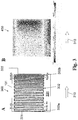
- FIG. 3B shows the temperature distribution on the heating surface of the infrared surface radiator 300 in the form of a diagram 400.
- the temperature of the heating surface increases continuously in the direction of the arrow 310, starting from an average temperature of approximately 550 ° C. in the left field of the infrared surface radiator 300 up to a temperature of 760 ° C in the right field of the infrared panel heater 300.
- FIG. 4 shows a fourth embodiment of an infrared radiator according to the invention, to which the reference number 500 is assigned.
- the infrared surface radiator 500 comprises a plate-shaped substrate 101, to which a conductor track 502 is applied by means of screen printing, as explained in the exemplary embodiment of FIG Figure 5 ..
- the substrate 101 With regard to the substrate 101, reference is made to the description Figure 1 referred. It points - different from the substrate 100 Figure 1 - A length l of 200mm, a width b of 100mm and a thickness of 2 mm.
- the conductor track 502 has five conductor track sections connected in series, which are identified by the reference numerals A to E.
- the conductor track sections B, D are identical; they have a conductor cross section of 0.01 mm 2 with a width of 0.05 mm and a thickness of 20 ⁇ m.
- the conductor track sections A, E are likewise of identical design and have a conductor cross section of 0.02 mm 2 with a width of 0.1 mm and a thickness of 20 ⁇ m.
- the conductor track section C has the same conductor track width and the same conductor cross section as the sections A, E only differs in length from the sections A, E.
- Section B has the same conductor track occupancy density as section D. However, the conductor track width in these sections is only half as large as that in the other sections A, E and C. Therefore, the conductor occupancy density in sections B and D is only 50% of that of the other sections.
- Figure 5 shows a fifth embodiment of an infrared surface radiator 600 according to the invention with a substrate 603, a conductor track 601 applied to the substrate 603 with five conductor track sections and a cover layer 602 covering the conductor track 601.
- the substrate 603 is made of the same material as the plate-shaped substrate 101 in Figure 1 . To the comments on this in Figure 1 is referred.
- the composite material from which the substrate 603 is made is an electrical insulator. It consists of a matrix component in the form of quartz glass. A phase of elemental silicon in the form of non-spherical areas is homogeneously distributed in the matrix, the proportion by weight of which is 5%. The maximum dimensions of the silicon phase areas are on average (median) in the range from approximately 1 ⁇ m to 10 ⁇ m.
- the composite material is gas-tight, it has a density of 2.19 g / cm3 and it is stable in air up to a temperature of around 1150 ° C.
- the composite material shows a high absorption of heat radiation and a high emissivity at high temperatures. This depends on the temperature. At 600 ° C the normal emissivity in the wavelength range from 2 ⁇ m to 4 ⁇ m is above 0.6. At 1,000 ° C, the normal emissivity in the same wavelength range is above 0.75.
- the conductor track 601 is made of a platinum paste which was applied to the substrate 603 by means of screen printing and then baked. On the conductor tracks 601, a thin cover layer 602 made of quartz glass is applied. This top layer of SiO 2 was applied using the thick film method in screen printing and has an average layer thickness of 20-50 ⁇ m. The layer is free of cracks and pores to protect the platinum from corrosive attacks.
- FIG 6 shows a further embodiment of an infrared radiator 700 according to the invention.
- the infrared radiator 700 differs from the infrared radiator 600 Figure 5 in the substrate composition.
- the substrate 705 is formed from two materials which are connected to one another in layers.
- the middle layer 704 consists of a conductive material with a high emissivity, namely SiC. Due to its electrical conductivity, layer 704 cannot be directly covered with conductor track 601. Layer 704 is therefore covered on both its top and bottom sides by layer 703 made of quartz glass.
- the layers 703 differ in their layer thickness.
- FIG 7 shows a seventh embodiment of an infrared radiator according to the invention, to which reference number 800 is assigned.
- the infrared surface radiator 800 has a substrate 805, which is made of the same materials as the substrate 705 Figure 6 consists.
- Material 704 forms a substrate core which is surrounded by a layer of material 703.
Landscapes
- Chemical & Material Sciences (AREA)
- Engineering & Computer Science (AREA)
- Ceramic Engineering (AREA)
- Resistance Heating (AREA)
- Surface Heating Bodies (AREA)
Description
- Die vorliegende Erfindung betrifft einen Infrarotflächenstrahler, aufweisend einen Träger mit einer Heizfläche und mit einer auf einer Leiterbahnbelegungsfläche des Trägers aufgebrachten Leiterbahn aus einem elektrisch leitenden und bei Stromdurchfluss wärmeerzeugenden Widerstandsmaterial, wobei die Leiterbahn einen ersten Leiterbahn-Abschnitt zur Erzeugung einer ersten Flächenleistung und einen zweiten Leiterbahn-Abschnitt zur Erzeugung einer von der ersten Flächenleistung abweichenden, zweiten Flächenleistung umfasst,
Infrarotflächenstrahler im Sinne der Erfindung zeigen eine Heizfläche mit flächig ausgedehnter, zwei- oder dreidimensionaler Abstrahlungscharakteristik; sie können aufgrund ihrer flächenhaften Abstrahlungscharakteristik einfach an die Geometrie einer zu beheizenden Oberfläche eines Heizguts angepasst werden, sodass eine homogene Bestrahlung zwei- oder dreidimensionaler Heizgut-Oberflächen ermöglicht wird. - Erfindungsgemäße Infrarotflächenstrahler werden insbesondere für thermische Heizprozesse eingesetzt, beispielsweise zur thermischen Behandlung von Halbleiterscheiben in der Halbleiter- oder Photovoltaik-Industrie, in der Druckindustrie oder der Kunststoffverarbeitung. Beispielsweise finden erfindungsgemäße Infrarotflächenstrahler Anwendung beim Polymerisieren von Kunststoffen, beim Aushärten von Lacken oder beim Trocknen von Farben. Sind darüber hinaus in einer Vielzahl von Trocknungsprozessen einsetzbar, beispielsweise bei der Herstellung von Folien oder Garnen oder der Fertigung von Modellen, Mustern, Prototypen, Werkzeugen oder Endprodukten (Additive Manufacturing). Ein weiteres wichtiges Anwendungsgebiet ist die Herstellung flexibler gedruckter Elektronik, insbesondere im Rolle-zu-Rolle-Verfahren (R2R-Verfahren), bei dem Trocknungs- und Sinterprozesse unmittelbar nacheinander ablaufen.
- Für die thermische Behandlung von Heizgütern werden häufig Infrarotflächenstrahler eingesetzt. Bekannte Infrarotflächenstrahler können unterschiedliche Bauformen aufweisen. Beispielsweise sind Infrarotflächenstrahler bekannt, bei denen mehrere Infrarotstrahler mit zylinderförmigem Strahlerrohr derart in einem Strahlermodul angeordnet sind, dass ihre Strahlerrohr-Längsachsen parallel zueinander in einer Ebene verlaufen. Weiterhin sind Infrarotflächenstrahler gemäß der eingangs genannten Gattung bekannt, bei denen ein Widerstands-Heizelement unmittelbar auf der Oberfläche eines flächigen Trägers aufgebracht ist.
- Die beiden zuvor beschriebenen Bauformen unterscheiden sich in der Wärmeübertragung. Während im erstgenannten Fall die Wärmeübertragung von einem in dem Strahlerrohr angeordneten Heizelement auf das Strahlerrohr vorrangig durch Wärmestrahlung erfolgt, steht im zweitgenannten Fall das Heizelement in unmittelbarem Kontakt mit dem flächigen Träger, sodass die Wärmeübertragung von dem Heizelement auf den Träger überwiegend durch Wärmeleitung und Konvektion erfolgt.
- Infrarotflächenstrahler mit einem auf den Träger aufgebrachten Heizelement zeigen eine gute Leistungseffizienz. Liegt bei diesen Infrarotflächenstrahlern eine Spannung am Widerstands-Heizelement an, wird dieses über seine gesamte Länge gesehen mit einer im Wesentlichen konstanten elektrischen Leistung betrieben.
- Es hat sich jedoch gezeigt, dass ein Betrieb eines Heizelements mit einer konstanten elektrischen Leistung mit Temperaturunterschieden, insbesondere einer ungleichmäßigen Temperaturverteilung auf der Heizfläche des Trägers einhergehen kann. Insbesondere an den Rändern des Trägers werden regelmäßig niedrigere Temperaturen gemessen als beispielsweise im Mittenbereich des Trägers. Ein Grund hierfür ist, dass im Träger-Randbereich gegenüber dem Mittenbereich höhere Energieverluste durch Konvektion auftreten können. Dies geht insbesondere im Randbereich des Trägers mit einer geringeren Temperatur und bezogen auf den gesamten Träger mit einer ungleichmäßigen Temperaturverteilung einher.
- Es ist daher bekannt, dass der Randbereich und der Mittenbereich eines Trägers unterschiedlich stark erwärmt werden müssen, um eine möglichst homogene Träger-Temperatur und damit einhergehend eine möglichst homogene Strahlungsemission der eigentlichen Heizfläche zu erhalten.
- Es sind Infrarotflächenstrahler mit flächigem Träger bekannt, bei denen die Leiterbahnmehrere, parallel geschaltete Leiterbahn-Abschnitte aufweist. Die Parallelschaltung soll dazu beitragen, dass die Leiterbahn einen möglichst geringen Gesamtwiderstand aufweist und daher mit hohen Betriebsströmen und damit einhergehend mit hohen Leistungen betrieben werden kann. Zur Kompensation von Randzonen-Effekten werden die Leiterbahn-Abschnitte mit unterschiedlichen Flächenleistungen betrieben, wobei die Leiterbahn-Abschnitte meist durch Einsatz von Drucktechniken erzeugt sind, beispielsweise durch Sieb- oder Tintenstrahldruck. In der Regel ist bei diesen Strahlern insbesondere dem Randbereich des Trägers ein Leiterbahn-Abschnitt zugeordnet, der mit einer höheren Flächenleistung betrieben werden kann. Dies hat den Vorteil, dass konvektionsbedingte Temperaturverluste im Bereich der Randzonen durch die höhere Flächenleistung der diesem Bereich zugeordneten Leiterbahn ausgeglichen werden können.
- Aus der
DE 10 2014 108 356 A1 ist ein Infrarotflächenstrahler bekannt, bei dem auf ein Träger eine Widerstandsstruktur aufgebracht ist. Die Widerstandsstruktur umfasst eine innenliegende Leiterbahn und eine parallel dazu geschaltete, außenliegende Leiterbahn, die sich in ihren Widerständen unterscheiden. Eine solche Widerstandsstruktur macht sich den Effekt zu Nutze, dass die Leiterbahn mit dem geringeren Widerstand einen höheren Beitrag zur Heizleistung beisteuert. Auf diese Weise wird der Ausbildung von sogenannten "cold spots" beziehungsweise einem Leistungsabfall im Bereich der Randzone entgegengewirkt. - Eine Parallelschaltung von Heizwiderständen hat den Vorteil, dass diese einen besonders niedrigen Gesamtwiderstand aufweist. Ein geringer Gesamtwiderstand geht bei vorgegebener, konstanter Betriebsspannung mit einer hohen Betriebsstromstärke einher und ermöglicht einen Betrieb des Infrarotflächenstrahlers mit hoher Leistung. Das Vorsehen parallel geschalteter Heizwiderstände hat allerdings Einfluss auf das Leiterbahn-Design, also die Anordnung und Geometrie der Leiterbahn-Abschnitte. Insbesondere können durch die gewünschte Temperaturverteilung die Widerstände der Parallelteilkreise und die Position der Parallelabzweigungen vom Hauptkreis vorgegeben sein. Hierbei kann es sein, dass durch die vorgegebene Position der Parallelkreis-Abzweigungen einerseits das Leiterbahn-Design nicht mehr frei wählbar ist. Darüber hinaus kann sich insbesondere im Bereich der Parallel-Abzweigung eine höhere Leiterbahn-Belegungsdichte ergeben, die wiederum Einfluss auf die Temperaturverteilung auf dem Träger, insbesondere der Heizfläche, haben kann.
-
DE 202 02 810 U1 betrifft einen elektrischen Flächenheizkörper mit einer Frontplatte, einer Trägerplatte und einer Halterung oder einem Fußteil, wobei die Trägerplatte aus nicht-stromleitendem Material mit geringem Wärmeausdehnungskoeffizienten eine beheizbare Deckschicht aufweist. -
US 2014/0314396 A1 betrifft ein elektrothermisches Element mit einem Substrat, einer Reflektorschicht, einer elektrothermischen Schicht und einer Hilfsschicht. -
WO 2012/139883 A1 betrifft einen Flächenheizkörper mit zumindest einem Substrat mit einer Substratfläche, einer elektrischen Heizschicht zum Heizen des Substrats, die durch Trennzonen elektrisch unterteilt ist. -
DE 11 2014 003 822 T5 betrifft eine Folienheizung für eine Heizplatte für das Heizen des Fahrgastraums eines Fahrzeugs. -
EP 0 495 770 A1 betrifft einen Infrarotstrahler aus einer Trägerplatte aus Stahlblech, das mit einem Dielektrikum auf keramischer Basis oder aus Email beschichtet ist oder aus Aluminiumoxid, auf die wenigstens eine Leiterbahn aus Metalloxid aufgebracht ist. -
FR 979 374 A - Der vorliegenden Erfindung liegt daher die technische Aufgabe zugrunde, einen Infrarotflächenstrahler mit hoher Bestrahlungsleistung anzugeben, der zur Emission von Strahlung mit einer möglichst gleichmäßigen Bestrahlungsstärke ausgelegt ist.
- Die oben genannte Aufgabe wird ausgehend von einem Infrarotflächenstrahler der eingangs genannten Gattung erfindungsgemäß dadurch gelöst, dass der Träger einen Komposit-Werkstoff enthält, der eine amorphe Matrixkomponente sowie eine in die amorphe Matrixkomponente eingelagerte Zusatzkomponente in Form eines Halbleitermaterials umfasst, und dass der erste Leiterbahn-Abschnitt und der zweite Leiterbahn-Abschnitt in Reihe geschaltet sind und sich in ihrer Belegungsdichte und/oder ihrem Leiterquerschnitt voneinander unterscheiden.
Der vorliegenden Erfindung liegt die Erkenntnis zugrunde, dass ein Infrarotflächenstrahler mit hoher Bestrahlungsstärke und besonders homogener Strahlungsemission erhalten werden kann, wenn dieser einerseits aus einem Komposit-Werkstoff mit hohem Emissionsgrad gefertigt ist und andererseits das Leiterbahn-Design durch Reihenschaltung mehrerer Leiterbahn-Abschnitte, auf den Komposit-Werkstoff abstimmbar ist, indem sich die Leiterbahn-Abschnitte in ihrer Belegungsdichte und/oder in ihrem Leiterquerschnitt voneinander unterscheiden. Durch diese Abstimmbarkeit wird erreicht, dass die Heizfläche IR-Strahlung mit einer homogenen Bestrahlungsstärke emittiert, oder anders gesagt: dass bei Anlegen einer Spannung an die Leiterbahn eine im wesentlichen gleichmäßige Temperaturverteilung auf der Heizfläche erhalten wird. - Der erfindungsgemäße Infrarotflächenstrahler unterscheidet sich somit von herkömmlichen Infrarotflächenstrahlern in zwei Gesichtspunkten, nämlich einerseits in der chemischen Zusammensetzung des Trägers oder mindestens eines Teils des Trägers, der aus einem spezifischen Komposit-Werkstoff gefertigt ist und andererseits im Leiterbahn-Design, das speziell auf die Zusammensetzung des Komposit-Werkstoffs abgestimmt ist.
- Dadurch, dass der Träger eine amorphe Matrixkomponente sowie eine Zusatzkomponente in Form eines Halbleitermaterials umfasst, wird ein Träger erhalten, das bei thermischer Anregung einen energiereichen, angeregten Zustand einnehmen kann. Insbesondere die physikalischen Eigenschaften des Trägers werden durch die Zusatzkomponente beeinflusst. Es hat sich gezeigt, dass durch den Zusatz eines Halbleitermaterials ein Träger erhalten wird, das zur Emission von Infrarotstrahlung mit hoher Bestrahlungsstärke geeignet ist. Gleichzeitig zeigt der Komposit-Werkstoff eine temperaturabhängige Wärmeleitfähigkeit, die ebenfalls auf dem Zusatz des Halbleitermaterials beruht.
- Der Komposit-Werkstoff umfasst dabei folgende Komponenten:
- Die amorphe Matrixkomponente stellt hinsichtlich Gewicht und Volumen den größten Anteil des Komposit-Werkstoffs dar. Sie bestimmt maßgeblich die mechanischen und chemischen Eigenschaften des Komposit-Werkstoffs; beispielsweise dessen Temperaturbeständigkeit, Festigkeit und Korrosionseigenschaften. Dadurch, dass die Matrixkomponente amorph ist - sie besteht vorzugsweise aus Glas - kann die geometrische Gestalt des Trägers im Vergleich zu einem Träger aus kristallinen Werkstoffen einfacher an die Anforderungen bei der spezifischen Anwendung des erfindungsgemäßen Infrarotflächenstrahlers angepasst werden.
Die Matrixkomponente kann aus undotiertem oder dotiertem Quarzglas bestehen und gegebenenfalls außer SiO2 in einer Menge bis maximal 10 Gew.- % andere oxidische, nitridische oder carbidische Komponenten enthalten. Zur Vermeidung einer vom Träger-Werkstoff ausgehenden Kontaminationsgefahr hat sich aber eine Ausführungsform des Infrarotflächenstrahlers besonders bewährt, bei dem die amorphe Matrixkomponente Quarzglas ist und vorzugsweise eine chemische Reinheit von mindestens 99,99 % SiO2 und ein Cristobalit-Gehalt von höchstens 1% besitzt. - Gemäß der Erfindung ist darüber hinaus vorgesehen, dass in die Matrixkomponente eine Zusatzkomponente in Form eines Halbleitermaterials eingelagert ist. Sie bildet eine eigene, in die amorphe Matrixkomponente dispergierte amorphe oder kristalline Phase. Sie trägt zu einem hohen Emissionsgrad bei, so dass ein Träger erhalten wird, der zur Emission von Infrarot-Strahlung mit hoher Strahlungsleistung geeignet ist.
- Bei dem erfindungsgemäßen Infrarotflächenstrahler dient die auf der Leiterbahnbelegungsfläche aufgebrachte Leiterbahn unmittelbar zur Erwärmung eines anderen Bauteils, nämlich des Trägers. Die Leiterbahn wirkt als "lokales" Heizelement, mit dem zumindest ein Teilbereich des Trägers lokal erwärmt werden kann; sie ist derart dimensioniert, dass sie einen Teil des Trägers erwärmt, der aus dem Komposit-Werkstoff gefertigt ist, der das eigentliche, Infrarotstrahlung emittierende Element des Trägers bildet. Dadurch, dass die Leiterbahn im Verbund mit dem Träger in unmittelbarem Kontakt mit der Leiterbahnbelegungsfläche des Trägers steht, wird ein besonders kompakter Infrarotflächenstrahler erhalten.
- Das Leiterbahn-Design und die elektrische Schaltung der Leiterbahn-Abschnitte sind an die physikalischen Eigenschaften des thermisch anregbaren Komposit-Werkstoffs angepasst.
- Die Wärmeleistung von herkömmlichen Infrarotflächenstrahlern, bei denen die Leiterbahn das eigentliche Heizelement bildet, hängt nach dem ohmschen Gesetz von dem elektrischen Gesamtwiderstand der Leiterbahn ab; bei ihnen kann die Wärmeleistung gesteigert werden, wenn der Leiterbahn-Gesamtwiderstandswert möglichst gering gewählt wird. Aus diesem Grund hat sich hier der Einsatz einer Parallelschaltung der Leiterbahn-Abschnitte als besonders günstig erwiesen, da ein Gesamtwiderstand erhalten wird, der kleiner ist als der kleinste Einzelwiderstand.
- Im Gegensatz hierzu zeigt der erfindungsgemäße Infrarotflächenstrahler einen materialbedingten Absorptionsbereich, in dem eine thermische Anregung des Trägers möglich ist. Da die Flächenleistung vom Absorptionsbereich abhängt, ist nicht-wie bei herkömmlichen Infrarotflächenstrahlern - ein möglichst niedriger Gesamtwiderstand wünschenswert, sondern es hat sich vielmehr gezeigt, dass eine optimierte, effiziente Wärmeleistung erreicht werden kann, wenn die Flächenleistungen der Leiterbahnen und damit einhergehend deren Gesamtwiderstand auf den materialbedingten Absorptionsbereich abgestimmt ist.
- Zur Erzielung einer optimalen Bestrahlungsstärke ist eine hinreichende thermische Anregung des Trägers notwendig. Dies wird erreicht, wenn die Leiterbahn und deren Abschnitte so geschaltet sind, dass genügend Energie zur thermischen Anregung des Trägers zur Verfügung steht. Ein darüber hinausgehender Energieeintrag trägt nur in begrenztem Umfang zur Steigerung der Bestrahlungsstärke bei und geht in der Regel mit einer geringeren Energieeffizienz einher.
- Die zur Anregung des Trägers notwendige Energie kann einfach und kostengünstig mit einer Reihenschaltung von Leiterbahn-Abschnitten zur Verfügung gestellt werden. In Bezug auf den thermisch anregbaren Komposit-Werkstoff des Trägers hat die Reihenschaltung von Leiterbahn-Abschnitten darüber hinaus den Vorteil, dass eine Anregung mit einem besonders günstigen Strom-Spannungs-Verhältnis ermöglicht wird. Durch die Reihenschaltung der Leiterbahn-Widerstände werden Betriebsspannungen im Bereich von 100 V bis 400 V möglich. Gleichzeitig wird ein Betrieb der Leiterbahn-Abschnitte geringeren Betriebsströmen möglich, wodurch die Lebensdauer des erfindungsgemäßen Infrarotflächenstrahlers erhöht werden kann.
- Schließlich kann dadurch, dass gemäß der Erfindung die Leiterbahn-Abschnitte in Reihe geschaltet sind, das Leiterbahn-Design flexibel an die jeweilige Anwendung angepasst werden. Insbesondere sind im Gegensatz zu einer Parallelschaltung von Leiterbahn-Abschnitten, bei der jeder Leiterbahn-Abschnitt einen Teilkreis bildet, keine Teilkreis-Abzweigungen notwendig, deren Position aufgrund des zu erzielenden Gesamtwiderstands vorgegeben sein können, sodass sie einer freien Gestaltung des Druckdesigns entgegenstehen können. Das frei wählbare Druckdesign ermöglicht eine Heizfläche mit einer besonders homogenen Bestrahlungsstärke, sodass eine besonders homogene thermische Behandlung des Heizguts ermöglicht wird.
- Zur Kompensation einer ungleichmäßigen Temperaturverteilung, insbesondere um konvektionsbedingte Randzonen-Effekte zu kompensieren, weist die Leiterbahn des erfindungsgemäßen Infrarotflächenstrahlers mehrere Abschnitte auf, die sich in den mit ihnen erzielbaren Flächenleistungen unterscheiden, nämlich mindestens einen ersten und einen zweiten Leiterbahn-Abschnitt, wobei die Belegungsdichte und/oder der Leiterquerschnitt des ersten und des zweiten Leiterbahn-Abschnitts so aufeinander abgestimmt sind, dass bei Anlegen einer Spannung an die Leiterbahn eine im wesentlichen gleichmäßige Temperaturverteilung auf der Heizfläche erhalten wird.
- Eine Einstellung der jeweiligen Flächenleistungen von erstem und zweitem Leiterbahn-Abschnitt kann beispielsweise über eine Variation der Belegungsdichte oder über eine Variation der Leiterquerschnitte der jeweiligen Leiterbahnen-Abschnitte oder über beides erfolgen.
- Die Flächenleistung ist dabei definiert als die elektrische Anschlussleistung der Leiterbahn bezogen auf die von der Leiterbahn belegte Träger-Fläche. Dabei gilt als Träger-Fläche diejenige Fläche, die von einer Umhüllenden um die Leiterbahn umschlossen ist, wobei die Umhüllenden benachbarter Leiterbahn-Abschnitte ohne Abstand zueinander mittig zwischen den benachbarten Leiterbahnen verlaufen und etwaige Stromzuführungsleitungen nicht berücksichtigt werden. Die Träger-Fläche gibt somit den individuellen Oberflächenbereich an, der einem Leiterbahnabschnitt zugeordnet ist. Die Flächenleistung in einem Leiterbahn-Abschnitt ist umso höher, je höher die Leiterbahn-Belegungsdichte und je geringer der Leiterbahn-Leiterquerschnitt ist.
- Der Leiterquerschnitt ist die in Stromflussrichtung betrachtete Querschnittsfläche durch die Leiterbahn. Bei einer schichtförmigen Leiterbahn mit Rechteckform ergibt sich der Leiterquerschnitt somit durch Multiplikation von Schichtbreite und Schichtdicke.
- Die Belegungsdichte ist ein Maß dafür, wie dicht ein Träger-Abschnitt mit einer Leiterbahn belegt ist. Die Belegungsdichte wird prozentual als Flächen-Verhältnis angegeben, indem die mit der Leiterbahn belegte Oberfläche (als Projektion auf die Leiterbahnbelegungsfläche) auf die Träger-Fläche bezogen wird. Die Träger-Fläche umfasst dabei sowohl die mit der Leiterbahn belegte als auch die nicht mit der Leiterbahn belegte, "freie" Oberfläche der Leiterbahnbelegungsfläche.
- Dadurch, dass die Leiterbahn mehrere solcher Leiterbahn-Abschnitte umfasst, wird die Ausbildung von Heizzonen ermöglicht, die sich in ihrer Flächenleistung unterscheiden. Die Heizzonen können so angeordnet werden, dass Temperaturverluste der Heizfläche ausgeglichen werden, sodass eine Heizfläche mit homogener Bestrahlungsstärke erhalten wird. Insbesondere ist eine Kompensation von Randzoneneffekten möglich, beispielsweise ist einer Randzone der Leiterbahnbelegungsfläche ein Leiterbahn-Abschnitt mit höherer Flächenleistung zugeordnet.
- Ein solcher Infrarotflächenstrahler weist eine Heizfläche auf, die zur Erzielung von Bestrahlungsstärken oberhalb von 200 kW/m2, vorzugsweise im Bereich von 200 kW/m2 bis 250 kW/m2 ausgelegt ist.
- Bei einer bevorzugten Ausgestaltung des erfindungsgemäßen Infrarotflächenstrahlers ist der Träger vollständig aus dem Komposit-Werkstoff gefertigt, wobei der Komposit-Werkstoff ein elektrischer Isolator ist.
- Der Träger mehrschichtig ausgeführt sein und außer dem Komposit-Werkstoff auch andere Werkstoffbereiche enthalten. Für den Betrieb des Infrarotflächenstrahlers ist es allerdings wesentlich, dass die Träger-Oberfläche zumindest im Bereich der Leiterbahnbelegungsfläche aus einem elektrisch isolierenden Werkstoff gefertigt ist. Hierdurch wird ein störungsarmer Betrieb des Infrarotflächenstrahlers gewährleistet, insbesondere werden Überschläge und Kurzschlüsse zwischen benachbarten Leiterbahn-Abschnitten verhindert. Dadurch, dass der Komposit-Werkstoff ein elektrischer Isolator ist, ist es möglich, die Leiterbahn unmittelbar auf den Komposit-Werkstoff und damit auf den Träger aufzubringen.
- Ein aus mehreren Werkstoffen gefertigter Träger kann beispielsweise eine Schichtstruktur aufweisen, in der zwei oder mehrere Werkstoff-Schichten übereinander angeordnet sein können. Alternativ ist es auch möglich, dass der Träger einen Kern aus einem ersten Werkstoff, vorzugsweise dem Komposit-Werkstoff, aufweist, der mit einem Überzug aus einem zweiten Werkstoff überzogen ist. Der Kern kann vollständig oder teilweise mit dem zweiten Werkstoff überzogen sein. Vorzugsweise ist der Kern vollständig mit dem zweiten Werkstoff überzogen.
- Bei einer bevorzugten Ausgestaltung des erfindungsgemäßen Infrarotflächenstrahlers ist der Komposit-Werkstoff zumindest im Bereich der Leiterbahnbelegungsfläche mit einer Schicht aus einem elektrisch isolierenden Werkstoff überzogen.
- Der Komposit-Werkstoff, aus dem der Träger gefertigt ist, zeigt einen guten Emissionsgrad im Infrarotbereich. Neben dem Emissionsgrad des Komposit-Werkstoffs sind für dessen Eignung als Träger eines Infrarotflächenstrahlers weitere physikalische Eigenschaften des Komposit-Werkstoffs von Bedeutung, insbesondere dessen elektrische Leitfähigkeit. Die physikalischen Eigenschaften des Komposit-Werkstoffs werden in erster Linie durch die Komponenten bestimmt, aus denen der Komposit-Werkstoff zusammengesetzt ist. Je nach chemischer Zusammensetzung ist es daher möglich, dass der Komposit-Werkstoff entweder ein elektrischer Isolator ist, oder aber eine gewisse elektrische Leitfähigkeit aufweist. Ein elektrisch leitfähiger Komposit-Werkstoff kann aus den oben genannten Gründen nicht unmittelbar mit einer Leiterbahn versehen werden, da es während des Betriebs des Infrarotflächenstrahlers zu Kurzschlüssen kommen kann. Um dennoch aus einem elektrisch leitfähigen Komposit-Werkstoff einen Träger fertigen zu können, hat es sich als günstig erwiesen, wenn dieser zunächst mit einer Schicht aus einem elektrisch isolierenden Werkstoff überzogen wird. Der Komposit-Werkstoff kann vollständig oder teilweise mit einem elektrisch isolierenden Werkstoff überzogen sein. Jedenfalls sollte zumindest der Bereich des Trägers, dem die Leiterbahn zugeordnet ist - also die Leiterbahnbelegungsfläche - mit einer Schicht aus einem elektrisch isolierenden Werkstoff überzogen sein, beispielsweise mit einer Schicht aus Glas, insbesondere aus Quarzglas.
- Bei einer weiteren bevorzugten Ausgestaltung des erfindungsgemäßen Infrarotflächenstrahlers ist vorgesehen, dass der Gewichtsanteil der Zusatzkomponente im Bereich zwischen 1 % und 5 %, vorzugsweise im Bereich zwischen 1,5 % und 3,5 % liegt.
- Die Wärmeabsorption des Komposit-Werkstoffs hängt vom Anteil der Zusatzkomponente ab. Der Gewichtsanteil der Zusatzkomponente sollte daher vorzugsweise mindestens 1 % betragen. Andererseits kann ein hoher Volumenanteil der Zusatzkomponente die chemischen und mechanischen Eigenschaften der Matrix beeinträchtigen. Im Hinblick darauf liegt der Gewichtsanteil der Zusatzkomponente bevorzugt im Bereich zwischen 1 % und 5 %, vorzugsweise im Bereich zwischen 1,5 % und 3,5 %.
- Es hat sich als günstig erwiesen, wenn die Leiterbahn als eingebrannte Dickfilmschicht ausgeführt ist oder wenn sie als Formstück derart auf die Oberfläche des Trägers aufgebracht ist, dass Leiterbahn und Träger dauerhaft miteinander verbunden sind.
- Die Herstellung einer Leiterbahn kann durch verschiedene Fertigungsmethoden erfolgen, beispielsweise unter Einsatz von Drucktechniken, aber auch durch Stanzen, Laserstrahlschneiden oder Gießen.
- Es hat sich als besonders günstig erwiesen, wenn die Leiterbahn als eingebrannte Dickfilmschicht ausgeführt ist. Derartige Dickfilmschichten werden beispielsweise aus Widerstandspaste mittels Siebdruck oder aus metallhaltiger Tinte mittels Tintenstrahldruck erzeugt und anschließend bei hoher Temperatur eingebrannt. Alternativ kann auch ein Formstück aus einem Blech unter Einsatz eines thermischen Trennverfahrens, beispielsweise durch Laserstrahlschneiden, oder durch Stanzen hergestellt sein. Der Einsatz thermischer Trenn- oder Stanzverfahren ermöglicht die Fertigung von Leiterbahnen in hoher Stückzahl und trägt so dazu bei, Material- und Fertigungskosten gering zu halten.
- Durch den Einsatz von thermischen Trenn- oder Stanzverfahren können auch Werkstoffe zu einer Leiterbahn verarbeitet werden, die mittels Drucktechniken kaum oder nur aufwendig verarbeitet werden können. Dadurch, dass die Leiterbahn aus einem elektrisch leitenden und bei Stromdurchfluss wärmeerzeugenden Widerstandsmaterial gefertigt ist, wirkt diese als Heizelement. Ein flächighomogen abstrahlender Infrarotstrahler mit hoher Strahlungsleistung wird allerdings erst dann erhalten, wenn die Leiterbahn mit dem Träger in Verbindung gebracht wird. Hierzu wird beispielsweise die Leiterbahn als Formstück auf die Oberfläche des Trägers aufgebracht und mit dem Träger dauerhaft verbunden. Dabei kann die Leiterbahn mit dem Träger sowohl mechanisch als auch thermisch gefügt werden oder über eine nicht-leitende Schicht verbunden werden. Im einfachsten Fall ist die Leiterbahn dem Träger in losem Verbund angefügt.
- Darüber hinaus ist es beim Einsatz von thermischen Trenn- oder Stanzverfahren möglich, Fertigungsfehler, die bei der Herstellung der Leiterbahn auftreten können, frühzeitig zu erkennen. Insbesondere gegenüber einer unter Einsatz von Drucktechniken hergestellten Leiterbahn ist es möglich, die Leiterbahn-Formstücke vor dem Verfahrensschritt des Fügens mit dem Träger auf ihre Funktionsfähigkeit zu überprüfen. Als separates Bauteil kann die Leiterbahn beispielsweise einfach mit einer Spannung beaufschlagt werden. Hierdurch ist es möglich, eine fehlerhafte Leiterbahn auszusortieren, und zwar bevor die fehlerhafte Leiterbahn mit dem Träger verbunden wird, sodass die Entstehung von Ausschuss verringert und dadurch Herstellungskosten gesenkt werden können.
- Es hat sich als günstig erwiesen, wenn die Leiterbahn aus Platin, hochtemperaturfestem Stahl, Tantal, einer ferritischen FeCrAl-Legierung, einer austenitischen CrFeNi-Legierung, Siliziumcarbid, Molydändisilicid oder einer Molybdän-Basislegierung gefertigt ist.
- Die vorgenannten Werkstoffe, insbesondere Siliziumcarbid (SiC), Molybdändisilicid (MoSi2), Tantal (Ta), hochwarmfester Stahl oder eine ferritsche FeCrAl-Legierung wie Kanthal® (Kanthal ist eine eingetragene Marke der SANDVIK INTELLECTUAL PROPERTY AB, 811 81, Sandviken, SE) sind im Vergleich zu Edelmetallen, beispielsweise Gold, Platin oder Silber, kostengünstig; sie können einfach zu einem Leiterbahn-Formkörper umgeformt werden, der als Halbzeug bei der Herstellung des Infrarotflächenstrahlers eingesetzt werden kann. Sie sind insbesondere als Bleche verfügbar, aus denen einfach und kostengünstig eine Leiterbahn gefertigt werden kann. Darüber hinaus haben die vorgenannten Materialien den Vorteil, dass sie an Luft oxidationsbeständig sind, sodass eine zusätzliche, die Leiterbahn bedeckende Schicht (Deckschicht) zum Schutz der Leiterbahnen nicht zwingend notwendig ist.
- Die Wärmeleistung eines jeden Leiterbahn-Abschnittes, ist abhängig vom spezifischen Widerstand des Widerstandsmaterials, der Leiterbahn-Abschnitt-Länge sowie dem Leiterquerschnitt. Durch Anpassung der Länge und des Leitungsquerschnitts ist eine einfache und schnelle Einstellung der Wärmeleistung des jeweiligen Leiterbahn-Abschnitts möglich.
- Dabei gilt: Je größer der Leiterquerschnitt eines Leiterbahn-Abschnitts ist, desto geringer ist sein Widerstand und umso geringer ist seine Flächenleistung bei konstanter Anschlussspannung. Der Gesamtwiderstand und der bei konstanter Anschlussspannung fließende Strom ergeben sich aus der Summe der in Reihe geschalteten Widerstände. Eine höhere Flächenleistung kann durch eine höhere Belegungsdichte mit Leitungen gleichen Querschnitts oder durch eine Erhöhung der Stromdichte oder durch einen dünneren Leitungsquerschnitt erzeugt werden.
- Es hat sich daher besonders bewährt, wenn der Leiterquerschnitt der Leiterbahn des ersten Leiterbahn-Abschnitts im Bereich von 0,01 mm2 bis 0,03 mm2 und der Leiterquerschnitt der Leiterbahn des zweiten Leiterbahn-Abschnitts zwischen 0,025 mm2 und 0,5 mm2 liegt.
- Es hat sich gezeigt, dass gute Ergebnisse hinsichtlich der Kompensation von Bestrahlungsstärke-Inhomogenitäten, wie sie üblicherweise bei Infrarotflächenstrahler beobachtet werden, erzielt werden können, wenn sich die Leiterquerschnittsflächen des ersten und des zweiten Leiterbahn-Abschnitts um mindestens 25 % voneinander unterscheiden. Vorzugsweise liegt der Unterschied der Leiterquerschnitte zwischen erstem und zweitem Leiterbahnabschnitt im Bereich von 30% bis 70%. bei Leiterquerschnitten von weniger als 0,01 mm2 kann sich das Aufbringen als schwierig erweisen und die mechanische Haftung ist gering. Leiterquerschnitte von mehr als 0,5 mm2 ergeben einen vergleichsweise geringen Widerstand und erfordern zum Beheizen daher relativ hohe Betriebsströme.
- Leiterquerschnitte im Bereich von 0,01 und 0,5 mm2 zeichnen sich durch ein besonders günstiges Spannungs-/Strom-Verhältnis aus; sie ermöglichen insbesondere einen Betrieb mit Spannungen im Bereich von 100 V bis 400 V bei Strömen von 1 A bis 4,5 A.
- Eine Variation der Leitbahn-Länge ist durch geeignete Wahl der Form der Leiterbahn möglich. Im Hinblick auf eine möglichst homogene Temperaturverteilung hat es sich als vorteilhaft erwiesen, wenn die Leiterbahn als Linienmuster ausgeführt ist, das eine Fläche des Trägers derart bedeckt, dass zwischen benachbarten Leiterbahn-Abschnitten ein Zwischenraum von mindestens 1 mm, bevorzugt mindestens 2 mm, verbleibt.
- Vorteilhafterweise ist die Leiterbahn als Linienmuster mit einer Belegungsdichte im Bereich von 25 % bis 85 % ausgeführt.
- Bei einer geringen Belegungsdichte von weniger als 25% kann sich die Leiterbahn aus Seite der Heizfläche als Inhomogenität im Temperaturverlauf abzeichnen. Die Erhöhung der Belegungsdichte auf mehr als 85 % bringt keinen nennenswerten Zugewinn an Flächenleistung mehr. Erster und zweiter Leiterbahn-Abschnitt können dieselben oder unterschiedliche Belegungsdichten aufweisen. Über die Belegungsdichte ist eine Einstellung der Flächenleistung möglich. Die Einstellung der Flächenleistung kann dabei sowohl über eine geeignete Wahl der Belegungsdichte als auch über eine geeignete Wahl der Leiterquerschnitte erfolgen. Ein Leiterbahn-Abschnitt mit hoher Flächenleistung wird erhalten, wenn dessen Leiterquerschnitt gering ist oder wenn der Leiterbahn-Abschnitt eine hohe Belegungsdichte aufweist. Eine möglichst exakte Einstellung der Flächenleistungen von erstem und zweitem Leiterbahn-Abschnitt wird ermöglicht, wenn sich die Leiterbahn-Abschnitte sowohl in ihrem Leiterquerschnitt als auch ihrer Belegungsdichte unterscheiden.
- Vorzugsweise liegt die Belegungsdichte des ersten Leiterbahn-Abschnitts bei maximal 75 % und die Belegungsdichte des zweiten Leiterbahn-Abschnitts im Bereich bei maximal 85%. Die zuvor genannten Belegungsdichten von erstem und zweitem Leiterbahn-Abschnitt sind einfach und kostengünstig herstellbar, beispielsweise durch Drucken.
- Bei einer bevorzugten Ausgestaltung des erfindungsgemäßen Infrarotflächenstrahlers ist vorgesehen, dass die Leiterbahn mehrere erste Leiterbahn-Abschnitte und mehrere zweite Leiterbahn-Abschnitte umfasst, wobei erste und zweite Leiterbahn-Abschnitte wechselweise aufeinander folgen.
- Durch das Vorsehen mehrerer, aufeinanderfolgender Leiterbahn-Abschnitte wird eine besonders flexible Anpassung der Bestrahlungsstärke und damit der Temperaturverteilung auf der Heizfläche ermöglicht, sodass die Ausbildung sogenannter "cold spots" oder "hot spots" vermieden werden kann. Dadurch, dass die mehreren Leiterbahn-Abschnitte in Reihe geschaltet sind, kann nahezu jedes beliebige Leiterbahn-Design realisiert werden.
- Es hat sich besonders bewährt, wenn zwischen dem ersten Leiterbahn-Abschnitt und dem zweiten Leiterbahn-Abschnitt ein dritter Leiterbahn-Abschnitt zur Erzeugung eines Flächenleistungsgradienten angeordnet ist.
- Ein Leiterbahn-Abschnitt korrespondiert mit einem Flächenbereich der Heizfläche, der mit einer konstanten Flächenleistung erwärmt wird. Der erste und der zweite Leiterbahn-Abschnitt können unmittelbar aneinander anschließen oder voneinander beanstandet sein. Ein gradueller Übergang zwischen dem ersten und dem zweiten Leiterbahn-Abschnitt trägt dazu bei, dass eine möglichst homogene Bestrahlungsleistung und eine homogene Temperaturverteilung auf der Heizfläche erzielt werden kann. Zu diesem Zweck kann zwischen dem ersten und dem zweiten Leiterbahn-Abschnitt ein dritter Leiterbahn-Abschnitt angeordnet sein, der derart ausgestaltet ist, dass er einen Flächenleistungsgradienten erzeugt. Hierdurch wird ein kontinuierlicher Übergang von der ersten Flächenleistung des ersten Leiterbahn-Abschnitts zur zweiten Flächenleistung des zweiten Leiterbahn-Abschnitts gewährleistet. Im einfachsten Fall ist der dritte Leiterbahn-Abschnitt so gestaltet, dass die Flächenleistung im dritten Leiterbahn-Abschnitt von der ersten Flächenleistung in die zweite Flächenleistung übergeht.
- Bei einer bevorzugten Ausgestaltung des erfindungsgemäßen Infrarotflächenstrahlers ist vorgesehen, dass die Leiterbahnbelegungsfläche einen Randbereich und einen Mittenbereich aufweist, wobei der erste Leiterbahn-Abschnitt eine höhere Flächenleistung als der zweite Leiterbahn-Abschnitt aufweist und dem Randbereich zugeordnet ist, und der zweite Leiterbahn-Abschnitt dem Mittenbereich zugeordnet ist.
- Es hat sich gezeigt, dass häufig der Randbereich eines Infrarotflächenstrahlers eine niedrigere Temperatur als der Mittenbereich aufweist. Eine Ursache hierfür ist, dass der Randbereich aufgrund seiner räumlichen Anordnung einem Wärmeabtransport besser zugänglich ist als der Mittenbereich. Es hat sich daher als günstig erwiesen, wenn insbesondere dem Randbereich ein Leiterbahn-Abschnitt mit höherer Flächenleistung zugeordnet ist, der den Wärmeabtransport kompensieren kann. Dies kann beispielsweise dadurch erreicht werden, dass die äußere Zone eine höhere Belegungsdichte oder einen geringeren Leiterquerschnitt aufweist.
- Die Zusatzkomponente bestimmt maßgeblich die optischen und thermischen Eigenschaften des Trägers; genauer gesagt, sie bewirkt eine Absorption im infraroten Spektralbereich, das ist der Wellenlängenbereich zwischen 780 nm und 1 mm. Die Zusatzkomponente zeigt für mindestens einen Teil der Strahlung in diesem Spektralbereich eine Absorption, die höher ist als die der Matrixkomponente.
- Die Phasenbereiche der Zusatzkomponente wirken in der Matrix als optische Störstellen und führen beispielsweise dazu, dass der Komposit-Werkstoff - je nach Schichtdicke - bei Raumtemperatur visuell schwarz oder grau-schwärzlich erscheinen kann. Außerdem wirken die Störstellen selbst wärmeabsorbierend.
- Im Komposit-Werkstoff liegt die Zusatzkomponente bevorzugt in einer Art und Menge vor, die im Komposit-Werkstoff bei einer Temperatur von 600 °C einen spektralen Emissionsgrad ε von mindestens 0,6 für Wellenlängen zwischen 2 µm und 8 µm bewirkt. Bei einer besonders bevorzugten Ausführungsform des erfindungsgemäßen Infrarotflächenstrahlers liegt die Zusatzkomponente in einer Art und Menge vor, die im Träger-Werkstoff bei einer Temperatur von 1.000 °C einen spektralen Emissionsgrad ε von mindestens 0,75 für Wellenlängen zwischen 2 µm und 8 µm bewirkt.
- Der Träger-Werkstoff verfügt demnach über ein hohes Absorptions- und Emissionsvermögen für Wärmestrahlung zwischen 2 µm und 8 µm, also im Wellenlängenbereich der infraroten Strahlung. Dies vermindert die Reflexion an den Träger-Oberflächen, sodass sich unter der Annahme einer vernachlässigbar geringen Transmission ein Reflexionsgrad für Wellenlängen zwischen 2 µm und 8 µm und bei Temperaturen oberhalb von 1.000 °C bei maximal 0,25 und bei Temperaturen von 600 °C von maximal 0,4 ergibt. Nicht reproduzierbare Aufheizungen durch reflektierte Wärmestrahlung werden so vermieden, was zu einer gleichmäßigen oder gewünscht ungleichmäßigen Temperaturverteilung beiträgt.
- Ein besonders hoher Emissionsgrad ist erzielbar, wenn die Zusatzkomponente als Zusatzkomponenten-Phase vorliegt und eine nicht-sphärische Morphologie mit maximalen Abmessungen von im Mittel weniger als 20 µm, vorzugsweise jedoch mehr als 3 µm aufweist.
- Die nicht-sphärische Morphologie der Zusatzkomponenten-Phase trägt dabei auch zu einer hohen mechanischen Festigkeit und zu einer geringen Rissbildungsneigung des Komposit-Werkstoffs bei. Die Angabe "maximale Abmessung" bezieht sich auf die in Schliff erkennbare längste Ausdehnung eines isolierten Bereichs mit Zusatzkomponenten-Phase. Der Medianwert aller längsten Ausdehnungen in einem Schliffbild bildet den oben genannten Mittelwert.
- Laut Kirchhoff'schem Strahlungsgesetz entsprechen spektraler Absorptionsgrad αλ und spektraler Emissionsgrad ελeines realen Körpers im thermischen Gleichgewicht einander.

- Die Zusatzkomponente führt somit dazu, dass der Träger-Werkstoff Infrarotstrahlung emittiert. Der spektrale Emissionsgrad ελ lässt sich bei bekannten gerichtethemisphärischen spektralen Reflexionsgrad Rgh und Transmissionsgrad Tgh wie folgt berechnen:

- Unter dem "spektralen Emissionsgrad" wird hierbei der "spektrale normale Emissionsgrad" verstanden. Dieser wird anhand eines Messprinzips ermittelt, das unter der Bezeichnung "Black-Body Boundary Conditions" (BBC) bekannt ist und veröffentlicht ist in "DETERMINING THE TRANSMITTANCE AND EMITTANCE OF TRANSPARENT AND SEMITRANSPARENT MATERIALS AT ELEVATED TEMPERATURES"; J. Manara, M. Keller, D. Kraus, M. Arduini-Schuster; 5th European Thermal-Sciences Conference, The Netherlands (2008).
- Die amorphe Matrixkomponente hat im Komposit-Werkstoff, also in Verbindung mit der Zusatzkomponente, eine höhere Wärmestrahlungsabsorption als dies ohne die Zusatzkomponente der Fall wäre. Dadurch ergibt sich eine verbesserte Wärmeleitung von der Leiterbahn in den Träger, eine schnellere Verteilung der Wärme und eine höhere Abstrahlungsrate auf den Träger. Dadurch gelingt es, eine höhere Strahlungsleistung pro Flächeneinheit bereitzustellen und auch bei dünnen Träger-Wandstärken und/oder bei einer vergleichsweise geringen Leiterbahn-Belegungsdichte eine homogene Abstrahlung und ein gleichförmiges Temperaturfeld zu erzeugen. Ein Träger mit einer geringen Wandstärke verfügt über eine geringe thermische Masse und ermöglicht schnelle Temperaturwechsel. Eine Kühlung ist dafür nicht erforderlich.
- Die Erfindung wird nachfolgend anhand von Ausführungsbeispielen und Zeichnungen näher erläutert. Dabei zeigt in schematischer Darstellung
- Figur 1
- eine erste Ausführungsform eines erfindungsgemäßen Infrarotflächenstrahlers mit einer Leiterbahn, die im Randbereich eine höhere Belegungsdichte als im Mittenbereich aufweist,
- Figur 2
- eine zweite Ausführungsform eines erfindungsgemäßen Infrarotflächenstrahlers mit einer Leiterbahn, die im Randbereich einen geringeren Leiterquerschnitt als im Mittenbereich aufweist,
- Figur 3
- eine dritte Ausführungsform eines erfindungsgemäßen Infrarotflächenstrahlers, sowie ein Wärmebild, das die Temperaturverteilung des Substrats auf der Seite der Leiterbahnbelegung dieses Infrarotflächenstrahlers zeigt,
- Figur 4
- eine vierte Ausführungsform eines erfindungsgemäßen Infrarotflächenstrahlers, bei der Leiterbahn-Abschnitte mit hohem und mit niedrigem elektrischem Widerstand wechselweise in Serie geschaltet sind,
- Figur 5
- eine fünfte Ausführungsform eines erfindungsgemäßen Infrarotflächenstrahlers mit einem Träger aus einem einzigen Werkstoff,
- Figur 6
- eine sechste Ausführungsform eines erfindungsgemäßen Infrarotflächenstrahlers mit einem Träger mit drei Werkstoff-Schichten, und
- Figur 7
- eine siebte Ausführungsform eines erfindungsgemäßen Infrarotflächenstrahlers, bei dem der Träger einen ummantelten Träger-Kern aufweist.
-
Figur 1 zeigt eine Draufsicht auf eine erste Ausführungsform eines erfindungsgemäßen Infrarotflächenstrahlers, dem insgesamt die Bezugsziffer 100 zugeordnet ist. Der Infrarotflächenstrahler 100 ist für den Einsatz in einer Vorrichtung zur Herstellung flexibler gedruckter Elektronik (nicht dargestellt) geeignet. Er weist ein plattenförmiges Substrat (das ist der Träger im Sinne dieser Erfindung) 101, eine auf das Substrat 101 aufgebrachte Leiterbahn 102, sowie zwei Leitungsbahnen 103a, 103b zur elektrischen Kontaktierung der Leiterbahn 102 auf. - Das plattenförmige Substrat 101 ist aus Quarzglas mit einer chemischen Reinheit von 99,99 % und einem Cristobalit-Gehalt von 0,25 % gefertigt, das mit einem Zusatz von elementarem Silizium in Höhe von 5 % der Gesamtmasse versehen ist. Die Phase aus elementarem Silizium ist in dem Quarzglas in Form nicht-sphärischer Bereiche homogen verteilt. Die maximalen Abmessungen der Si-Phasenbereiche liegen im Mittel (Medianwert) im Bereich 1 µm bis 10 µm. Das plattenförmige Substrat 101 hat eine Dichte von 2,19 g/cm3 und es hat eine Länge L von 100 mm, eine Breite B von 100 mm und eine Dicke von 2 mm. Das plattenförmige Substrat 101 wirkt visuell schwarz.
- Die eingelagerte Si-Phase trägt einerseits zur Opazität des Substrats 101 insgesamt bei und sie hat Auswirkungen auf dessen optische und thermische Eigenschaften. Es zeigt bei hoher Temperatur eine hohe Absorption von Wärmestrahlung und einen hohen Emissionsgrad.
- Bei Raumtemperatur wird der Emissionsgrad des Komposit-Werkstoffs unter Einsatz einer Ulbrichtkugel gemessen. Diese erlaubt die Messung des gerichtet hemisphärischen spektralen Reflexionsgrades Rgh und des gerichtethemisphärischen spektralen Transmissionsgrades Tgh, woraus der normale spektrale Emissionsgrad berechnet wird. Die Messung des Emissionsgrades bei erhöhter Temperatur erfolgt im Wellenlängenbereich von 2 bis 18 µm mittels eines FTIR-Spektrometers (Bruker IFS 66v Fourier-Transformations Infrarot (FTIR)), an das über eine Zusatzoptik eine BBC-Probenkammer angekoppelt wird, anhand des oben genannten BBC-Messprinzips. Die Probenkammer verfügt dabei in den Halbräumen vor und hinter der Probenhalterung über temperierbare Schwarzkörperumgebungen und eine Strahlausgangsöffnung mit Detektor. Die Probe wird in einem separaten Ofen auf eine vorgegebene Temperatur aufgeheizt und zur Messung in den Strahlengang der Probenkammer mit den auf vorgegebene Temperatur eingestellten Schwarzkörperumgebungen verbracht. Die vom Detektor erfasste Intensität setzt sich aus einem Emissions-, einem Reflexions- und einem Transmissionsanteil zusammen, nämlich aus Intensität, die von der Probe selbst emittiert wird, Intensität, die vom vorderen Halbraum auf die Probe fällt und von dieser reflektiert wird, sowie Intensität, die vom hinteren Halbraum auf die Probe fällt und von dieser transmittiert wird. Zur Ermittlung der einzelnen Größen Emissions-, Reflexions- und Transmissionsgrad müssen drei Messungen durchgeführt werden.
- Der am Substrat 101 gemessene Emissionsgrad im Wellenlängenbereich von 2 µm bis etwa 4 µm hängt von der Temperatur ab. Je höher die Temperatur ist, umso höher ist die Emission. Bei 600 °C liegt der normale Emissionsgrad im Wellenlängenbereich von 2 µm bis 4 µm oberhalb von 0,6. Bei 1000 °C liegt der normale Emissionsgrad im gesamten Wellenlängenbereich zwischen 2 µm und 8 µm oberhalb von 0,75.
- Die Leiterbahn 102 ist aus einer Platin-Widerstandspaste erzeugt, in dem diese auf der Leiterbahnbelegungsfläche 104 des plattenförmigen Substrats 101 aufgedruckt und anschließend eingebrannt wurde. Die Leiterbahn 102 weist einen mäanderförmigen Verlauf auf und umfasst zwei Leiterbahn-Abschnitte 105, 106, wobei der erste Leiterbahn-Abschnitt 105 im Randbereich des Substrats 101 und der zweite Leiterbahn-Abschnitt 106 dem Mittenbereich des Substrats 101 zugeordnet ist. Um einer konvektionsbedingten, inhomogenen Temperaturverteilung auf dem Substrat 101 entgegenwirken zu können, ist der dem Randbereich zugeordnete Leiterbahn-Abschnitt 105 mit einer höheren Belegungsdichte auf das Substrat 101 aufgebracht als der dem Mittenbereich zugeordnete Leiterbahn-Abschnitt 106. Die Belegungsdichte des Leiterbahn-Abschnitts 105 beträgt 80 % und die Belegungsdichte des Leiterbahn-Abschnitts 106 beträgt 40 %, im Mittenbereich beträgt der Abstand b benachbarter Leiterbahnen 4,2 mm, im Randbereich beträgt der Abstand a benachbarter Leiterbahnen 0,7 mm.
- Die Leiterbahn-Abschnitte 105, 106 zeichnen sich durch eine Querschnittsfläche von 0,028 mm2 bei einer Breite von 2,8 mm und einer Dicke von 10 µm aus.
- Sofern bei den in anderen Figuren gezeigten Ausführungsformen dieselben Bezugsziffern wie in
Figur 1 verwendet sind, so sind damit baugleiche oder äquivalente Bauteile und Bestandteile bezeichnet, wie sie oben anhand der Beschreibung vonFigur 1 näher erläutert sind. -
Figur 2 zeigt eine zweite Ausführungsform eines erfindungsgemäßen Infrarotflächenstrahlers, dem insgesamt die Bezugsziffer 200 zugeordnet ist. Der Infrarotflächenstrahler 200 umfasst ein plattenförmiges Substrat 101 eine auf das Substrat 101 aufgebrachte Leiterbahn 202, sowie zwei Leitungsbahnen 103a, 103b. - Der Infrarotflächenstrahler 200 unterscheidet sich von dem aus
Figur 1 bekannten Infrarotflächenstrahler 100 im Wesentlichen im Leiterbahn-Design. Hinsichtlich des Substrats 101 wird auf die Beschreibung zuFigur 1 verwiesen. - Die Leiterbahnen 202 ist aus einer Platin-Widerstandspaste erzeugt, in dem diese auf die Oberseite 204 des plattenförmigen Substrats 101 aufgedruckt und anschließend eingebrannt wurde. Die Leiterbahn 202 weist einen mandelförmigen Verlauf auf und umfasst zwei Leiterbahn-Abschnitte 205, 206, wobei der erste Leiterbahn-Abschnitt 205 dem Randbereich des Substrats 101 und der zweite Leiterbahn-Abschnitt 206 dem Mittenbereich des Substrats 101 zugeordnet ist. Um einer konvektionsbedingten, inhomogenen Temperaturverteilung auf dem Substrat 101 entgegenwirken zu können, weist der dem Randbereich zugeordnete Leiterbahn-Abschnitt 205 einen höheren Widerstand als der dem Mittenbereich zugeordnete Leiterbahn-Abschnitt 206 auf. Der Leiterbahn-Abschnitt 205 hat einen Leiterquerschnitt von 0,02 mm2 bei einer Breite von 0,02 mm und einer Dicke von 10 µm. Der Leiterbahn-Abschnitt 206 hat einen Leiterquerschnitt von 0,028 mm2 bei einer Breite von 2,8 mm und einer Dicke von 10 µm.
- Im Mittenbereich beträgt der Abstand b benachbarter Leiterbahnen 4,18 mm; im Randbereich beträgt der Abstand a benachbarter Leiterbahnen 4,98 mm. Die Leiterbahnbreite (und damit auch der Leiterquerschnitt) ist im Mittenbereich 206 jedoch größer als im Randbereich 205, so dass die Abschnitte 205, 206 keine einheitliche Leiterbahn-Belegungsdichte haben. Im Mittenbereich 206 ergibt sich eine Belegungsdichte von 40%; und im Randbereich von 28,8%, bezogen auf die von der jeweiligen Leiterbahn belegte Träger-Fläche, die durch grau hinterlegte Flächenbereiche 205a (für die Träger-Fläche des Randbereichs 205) beziehungsweise 206a (für die Träger-Fläche des Mittenbereichs 206) repräsentiert sind.
-
Figur 3A zeigt eine dritte Ausführungsform eines erfindungsgemäßen Infrarotflächenstrahlers, dem insgesamt die Bezugsziffer 300 zugeordnet ist. Der Infrarotflächenstrahler 300 umfasst ein Substrat 101, wie es anhand vonFigur 1 näher beschrieben ist. Auf das Substrat 101 ist eine Leiterbahn 302 aufgebracht, die an ihren Enden mit Leitungsbahnen 303a, 303b versehen ist. Die Leiterbahn 302 ist zur Erzeugung eines Temperaturgradienten ausgelegt. - Zu diesem Zweck ist die auf die Oberfläche 304 des Substrats 101 aufgebrachte Leiterbahnen 302 derart ausgebildet, dass die Abstände x0 bis x22 benachbarter Leiterbahnen in Pfeilrichtung 310 gesehen kontinuierlich abnehmen, sodass die Belegungsdichte in Pfeilrichtung 310 gesehen zunimmt. Die Belegungsdichte beträgt im ersten Leiterbahn-Endabschnitt 321 40% und sie nimmt kontinuierlich zu bis sie im zweiten Leiterbahn-Endabschnitt 322 91 % beträgt.
- Die Leiterbahnen 302 wird durch Siebdruck erzeugt, wie dies weiter unten anhand des Ausführungsbeispiels von
Figur 5 noch näher erläutert wird. Die Leiterbahn 302 weist in Pfeilrichtung 310 gesehen einen mäanderförmigen Verlauf auf. Die Leiterbahn 302 hat einen Leiterquerschnitt von 0,02 mm2 bei einer Breite von 0,1 mm und einer Dicke von 20 µm. - Der Infrarotflächenstrahler 300 ist in einer Vorrichtung (nicht dargestellt) einsetzbar, die zur Herstellung flexibler gedruckter Elektronik im Rolle-zu-Rolle-Verfahren (R2R-Verfahren) bestimmt ist. In dieser Vorrichtung ist der Infrarotflächenstrahler 300 so angeordnet, dass die Transportrichtung (von Rolle zu Rolle) der Pfeilrichtung 310 entspricht. Hierdurch wird ermöglicht, dass zu Beginn der Bestrahlung eine geringe Leistung bereitgestellt wird, wie sie beispielsweise zum Trocknen der gedruckten Elektronik benötigt wird. Dadurch, dass die Belegungsdichte des Infrarotflächenstrahlers 300 in Transportrichtung gesehen zunimmt, wird das Heizgut während des Transports mit zunehmend höheren Bestrahlungsleistungen bestrahlt bis es am Ende des Bestrahlungsprozesses einer hohen Leistung exponiert ist, wie sie beispielsweise zum Sintern der gedruckten Elektronik benötigt wird. Die Bestrahlungsleistung beträgt zu Beginn des Bestrahlungsprozesses 50 kW/m2 und nimmt kontinuierlich zu bis am Ende 150 kW/m2 erreicht werden.
- Dieser Gradient spiegelt sich auch in der Temperaturverteilung auf der Heizfläche des Infrarotflächenstrahlers 300 wider.
Figur 3B zeigt in Form eines Diagramms 400 die Temperaturverteilung auf der Heizfläche des Infrarotflächenstrahlers 300. In Abhängigkeit von der Belegungsdichte nimmt in Pfeilrichtung 310 gesehen die Temperatur der Heizfläche kontinuierlich zu, und zwar ausgehend von einer mittleren Temperatur von etwa 550 °C im linken Feld des Infrarotflächenstrahlers 300 bis auf eine Temperatur von 760 °C im rechten Feld des Infrarotflächenstrahlers 300. -
Figur 4 zeigt eine vierte Ausführungsform eines erfindungsgemäßen Infrarotflächenstrahlers, dem insgesamt die Bezugsziffer 500 zugeordnet ist. Der Infrarotflächenstrahler 500 umfasst ein plattenförmiges Substrat 101, auf das eine Leiterbahn 502 mittels Siebdruck aufgebracht ist, wie erläutert im nachfolgend beschriebenen Ausführungsbeispiel vonFigur 5 .. - Hinsichtlich des Substrats 101 wird auf die Beschreibung zu
Figur 1 verwiesen. Es weist - abweichend von dem Substrat 100 ausFigur 1 - eine Länge l von 200mm, eine Breite b von 100mm und eine Dicke von 2 mm auf. - Die Leiterbahn 502 weist fünf in Reihe geschaltete Leiterbahn-Abschnitte auf, die mit den Bezugszeichen A bis E gekennzeichnet sind. Die Leiterbahn-Abschnitte B, D sind identisch ausgebildet; sie haben einen Leiterquerschnitt von 0,01 mm2 bei einer Breite von 0,05 mm und einer Dicke von 20 µm. Die Leiterbahnen-Abschnitte A, E sind ebenfalls identisch ausgebildet und weisen einen Leiterquerschnitt von 0,02 mm2 bei einer Breite von 0,1 mm und einer Dicke von 20 µm auf. Der Leiterbahn-Abschnitt C hat dieselbe Leiterbahnbreite und denselben Leiterquerschnitt wie die Abschnitte A, E unterscheidet sich lediglich in der Länge von den Abschnitten A, E. Abschnitt B hat dieselbe Leiterbahn-Belegungsdichte wie Abschnitt D. Die Leiterbahnbreite in diesen Abschnitten ist aber nur halb so groß wie die in den anderen Abschnitten A, E und C. Daher beträgt auch die Leiterbahn-Belegungsdichte in den Abschnitten B und D nur 50 % derjenigen der übrigen Abschnitte.
-
Figur 5 zeigt eine fünfte Ausführungsform eines erfindungsgemäßen Infrarotflächenstrahlers 600 mit einem Substrat 603, einer auf das Substrat 603 aufgebrachten Leiterbahn 601 mit fünf Leiterbahn-Abschnitten und einer die Leiterbahn 601 bedeckende Deckschicht 602. - Das Substrat 603 ist aus demselben Werkstoff gefertigt wie das plattenförmige Substrat 101 in
Figur 1 . Auf die Ausführungen hierzu inFigur 1 wird verwiesen. Der Komposit-Werkstoff, aus dem das Substrat 603 gefertigt ist, ist ein elektrischer Isolator. Er besteht aus einer Matrixkomponente in Form von Quarzglas. In der Matrix ist eine Phase aus elementarem Silizium in Form nicht-sphärischer Bereiche homogen verteilt, deren Gewichtsanteil 5 % beträgt. Die maximalen Abmessungen der Silizium-Phasenbereiche liegen im Mittel (Medianwert) im Bereich von etwa 1 µm bis 10 µm. Der Komposit-Werkstoff ist gasdicht, er hat eine Dichte von 2,19 g/cm3 und er ist an Luft bis zu einer Temperatur von etwa 1150 °C stabil. Der Komposit-Werkstoff zeigt bei hohen Temperaturen eine hohe Absorption von Wärmestrahlung und einen hohen Emissionsgrad. Dieser hängt von der Temperatur ab. Bei 600 °C liegt der normale Emissionsgrad im Wellenlängenbereich von 2 µm bis 4 µm oberhalb von 0,6. Bei 1.000 °C liegt der normale Emissionsgrad im selben Wellenlängenbereich oberhalb von 0,75. - Die Leiterbahn 601 ist aus einer Platinpaste gefertigt, die auf das Substrat 603 mittels Siebdruck aufgetragen und anschließend eingebrannt wurde. Auf die Leiterbahnen 601 ist eine dünne Deckschicht 602 aus Quarzglas aufgebracht. Diese Deckschicht aus SiO2 wurde über das Dickfilmverfahren im Siebdruck aufgebracht und hat eine mittlere Schichtdicke von 20-50 µm. Die Schicht ist riss- und porenfrei, um das Platin vor korrosiven Angriffen zu schützen.
- Sofern in den in den
Figuren 6 und 7 gezeigten Ausführungsformen dieselben Bezugsziffern wie inFigur 5 verwendet sind, so sind damit baugleiche oder äquivalente Bauteile und Bestandteile bezeichnet, wie sie oben anhand der Beschreibung vonFigur 5 näher erläutert sind. -
Figur 6 zeigt eine weitere Ausführungsform eines erfindungsgemäßen Infrarotflächenstrahlers 700. Der Infrarotflächenstrahler 700 unterscheidet sich von dem Infrarotflächenstrahler 600 ausFigur 5 in der Substratzusammensetzung. Das Substrat 705, ist aus zwei Werkstoffen gebildet, die schichtartig miteinander verbunden sind. Die mittlere Schicht 704 besteht aus einem leitfähigen Material mit hohem Emissionsgrad, nämlich aus SiC. Die Schicht 704 kann aufgrund ihrer elektrischen Leitfähigkeit nicht unmittelbar mit der Leiterbahn 601 belegt werden. Die Schicht 704 ist daher an ihrer Ober- und an ihrer Unterseite jeweils von Schicht 703 aus Quarzglas bedeckt. Die Schichten 703 unterscheiden sich in ihrer Schichtdicke. -
Figur 7 zeigt eine siebte Ausführungsform eines erfindungsgemäßen Infrarotflächenstrahlers, dem die Bezugsziffer 800 zugeordnet ist. Der Infrarotflächenstrahler 800 weist ein Substrat 805 auf, das aus denselben Werkstoffen wie das Substrat 705 ausFigur 6 besteht. Der Werkstoff 704 bildet einen Substrat-Kern der von einer Schicht aus dem Werkstoff 703 umgeben ist.
Claims (15)
- Infrarotflächenstrahler (100, 200, 300, 500, 600, 700, 800), aufweisend einen Träger mit einer Heizfläche und mit einer auf einer Leiterbahnbelegungsfläche des Trägers aufgebrachten Leiterbahn (102, 202, 302, 502, 601) aus einem elektrisch leitenden und bei Stromdurchfluss wärmeerzeugenden Widerstandsmaterial, wobei die Leiterbahn (102, 202, 302, 502, 601) einen ersten Leiterbahn-Abschnitt (105, 205) zur Erzeugung einer ersten Flächenleistung und einen zweiten Leiterbahn-Abschnitt (106, 206) zur Erzeugung einer von der ersten Flächenleistung abweichenden, zweiten Flächenleistung umfasst, wobei der erste Leiterbahn-Abschnitt (105, 205) und der zweite LeiterbahnAbschnitt (106, 206) in Reihe geschaltet sind und sich in ihrer Belegungsdichte und/oder ihrem Leiterquerschnitt voneinander unterscheiden, dadurch gekennzeichnet, dass der Träger einen Komposit-Werkstoff enthält, der eine amorphe Matrixkomponente sowie eine in die amorphe Matrixkomponente eingelagerte Zusatzkomponente in Form eines Halbleitermaterials umfasst.
- Infrarotflächenstrahler (100, 200, 300, 500, 600, 700, 800) nach Anspruch 1, dadurch gekennzeichnet, dass der Träger vollständig aus dem Komposit-Werkstoff gefertigt ist, wobei der Komposit-Werkstoff ein elektrischer Isolator ist.
- Infrarotflächenstrahler (100, 200, 300, 500, 600, 700, 800) nach Anspruch 1, dadurch gekennzeichnet, dass der Komposit-Werkstoff zumindest im Bereich der Leiterbahnbelegungsfläche mit einer Schicht aus einem elektrisch isolierenden Werkstoff überzogen ist.
- Infrarotflächenstrahler (100, 200, 300, 500, 600, 700, 800) nach einem der vorhergehenden Ansprüche, dadurch gekennzeichnet, dass der Gewichtsanteil der Zusatzkomponente im Bereich zwischen 1 % und 5 %, vorzugsweise im Bereich zwischen 1,5 % und 3,5 % liegt.
- Infrarotflächenstrahler (100, 200, 300, 500, 600, 700, 800) nach einem der vorhergehenden Ansprüche, dadurch gekennzeichnet, dass die Leiterbahnen (102, 202, 302, 502, 601) als eingebrannte Dickfilmschicht ausgeführt ist oder als Formstück derart auf die Oberfläche des Trägers aufgebracht ist, dass Leiterbahn (102, 202, 302, 502, 601) und Träger dauerhaft miteinander verbunden sind.
- Infrarotflächenstrahler (100, 200, 300, 500, 600, 700, 800) nach einem der vorhergehenden Ansprüche, dadurch gekennzeichnet, dass die Leiterbahn (102, 202, 302, 502, 601) als Linienmuster mit einer Belegungsdichte im Bereich von 25 % bis 85 % ausgeführt ist.
- Infrarotflächenstrahler (100, 200, 300, 500, 600, 700, 800) nach einem der vorhergehenden Ansprüche, dadurch gekennzeichnet, dass die Leiterbahn (102, 202, 302, 502, 601) im ersten Leiterbahn-Abschnitt (105, 205) einen Leiterquerschnitt im Bereich von 0,01 bis 0,03 mm2 und die Leiterbahn im zweiten Leiterbahn-Abschnitt (106, 206) einen Leiterquerschnitt im Bereich von 0,025 bis 0,5 mm2 hat.
- Infrarotflächenstrahler (100, 200, 300, 500, 600, 700, 800) nach einem der vorhergehenden Ansprüche, dadurch gekennzeichnet, dass die Leiterbahn (102, 202, 302, 502, 601) mehrere erste Leiterbahn-Abschnitte und mehrere zweite Leiterbahn-Abschnitte umfasst, wobei erste und zweite Leiterbahnenabschnitte wechselweise aufeinander folgen.
- Infrarotflächenstrahler (100, 200, 300, 500, 600, 700, 800) nach einem der vorhergehenden Ansprüche, dadurch gekennzeichnet, dass zwischen dem ersten Leiterbahn-Abschnitt und dem zweiten Leiterbahn-Abschnitt ein dritter Leiterbahn-Abschnitt zur Erzeugung eines Flächenleistungsgradienten angeordnet ist.
- Infrarotflächenstrahler (100, 200, 300, 500, 600, 700, 800) nach einem der vorhergehenden Ansprüche, dadurch gekennzeichnet, dass die Leiterbahnbelegungsfläche einen Randbereich und einen Mittenbereich aufweist, wobei der erste Leiterbahn-Abschnitt (105, 205) eine höhere Flächenleistung als der zweite Leiterbahn-Abschnitt (106, 206) aufweist und dem Randbereich zugeordnet ist, und der zweite Leiterbahn-Abschnitt (106, 206) dem Mittenbereich zugeordnet ist.
- Infrarotflächenstrahler (100, 200, 300, 500, 600, 700, 800) nach einem der vorhergehenden Ansprüche, dadurch gekennzeichnet, dass die Heizfläche eine Bestrahlungsleistung im Bereich von 200 kW/m2 bis zu 250 kW/m2 hat.
- Infrarotflächenstrahler (100, 200, 300, 500, 600, 700, 800) nach einem der vorhergehenden Ansprüche, dadurch gekennzeichnet, dass die Zusatzkomponente eine eigene, in die amorphe Matrixkomponente dispergierte amorphe oder kristalline Phase bildet.
- Infrarotflächenstrahler (100, 200, 300, 500, 600, 700, 800) nach einem der vorhergehenden Ansprüche, dadurch gekennzeichnet, dass die Zusatzkomponente in einer Art und Menge vorliegt, die im Komposit-Werkstoff bei einer Temperatur von 600 °C einen spektralen Emissionsgrad ε von mindestens 0,6 für Wellenlängen zwischen 2 µm und 8 µm bewirkt.
- Infrarotflächenstrahler (100, 200, 300, 500, 600, 700, 800) nach einem der vorhergehenden Ansprüche, dadurch gekennzeichnet, dass die Zusatzkomponente in einer Art und Menge vor liegt, die im Träger-Werkstoff bei einer Temperatur von 1.000 °C einen spektralen Emissionsgrad ε von mindestens 0,75 für Wellenlängen zwischen 2 µm und 8 µm bewirkt.
- Infrarotflächenstrahler (100, 200, 300, 500, 600, 700, 800) nach einem der vorhergehenden Ansprüche, dadurch gekennzeichnet, dass die Zusatzkomponente als Zusatzkomponenten-Phase vorliegt und eine nicht-sphärische Morphologie mit maximalen Abmessungen von im Mittel weniger als 20 µm, vorzugsweise jedoch mehr als 3 µm aufweist.
Applications Claiming Priority (2)
| Application Number | Priority Date | Filing Date | Title |
|---|---|---|---|
| DE102016118137.4A DE102016118137A1 (de) | 2016-09-26 | 2016-09-26 | Infrarotflächenstrahler |
| PCT/EP2017/071086 WO2018054629A1 (de) | 2016-09-26 | 2017-08-22 | Infrarotflächenstrahler |
Publications (2)
| Publication Number | Publication Date |
|---|---|
| EP3516925A1 EP3516925A1 (de) | 2019-07-31 |
| EP3516925B1 true EP3516925B1 (de) | 2020-06-17 |
Family
ID=59686957
Family Applications (1)
| Application Number | Title | Priority Date | Filing Date |
|---|---|---|---|
| EP17755502.6A Active EP3516925B1 (de) | 2016-09-26 | 2017-08-22 | Infrarotflächenstrahler |
Country Status (8)
| Country | Link |
|---|---|
| US (1) | US20190208579A1 (de) |
| EP (1) | EP3516925B1 (de) |
| JP (1) | JP6771657B2 (de) |
| KR (1) | KR102276922B1 (de) |
| CN (1) | CN109716858A (de) |
| DE (1) | DE102016118137A1 (de) |
| TW (1) | TWI662858B (de) |
| WO (1) | WO2018054629A1 (de) |
Families Citing this family (18)
| Publication number | Priority date | Publication date | Assignee | Title |
|---|---|---|---|---|
| DE102016120536A1 (de) * | 2016-10-27 | 2018-05-03 | Heraeus Noblelight Gmbh | Infrarotstrahler |
| DE102018125304A1 (de) * | 2018-10-12 | 2020-04-16 | Heraeus Noblelight Gmbh | Heizeinrichtung mit einem Infrarot-Flächenstrahler |
| CN110940696B (zh) * | 2019-11-28 | 2022-04-26 | 航天特种材料及工艺技术研究所 | 一种用于热导率测试的均温性加热装置 |
| CN110907491B (zh) * | 2019-11-28 | 2022-06-28 | 航天特种材料及工艺技术研究所 | 一种低导热材料高温热导率测试装置 |
| CN110940695B (zh) * | 2019-11-28 | 2022-04-26 | 航天特种材料及工艺技术研究所 | 一种热量汇聚装置 |
| CN110907493B (zh) * | 2019-11-28 | 2022-05-27 | 航天特种材料及工艺技术研究所 | 一种高温热导率的测试方法 |
| CN110933784B (zh) * | 2019-11-28 | 2022-02-15 | 航天特种材料及工艺技术研究所 | 一种一维传热高温均匀加热板及加热装置 |
| CN110907490B (zh) * | 2019-11-28 | 2022-02-11 | 航天特种材料及工艺技术研究所 | 一种高导热材料的热导率测试装置及方法 |
| EP3904846A1 (de) * | 2020-04-29 | 2021-11-03 | Infineon Technologies AG | Wärmestrahler mit eingebettetem heizelement |
| US12106957B2 (en) * | 2020-04-30 | 2024-10-01 | Taiwan Nano & Micro-Photonics Co., Ltd. | Narrow band infrared emitter through thermal manner |
| CN111935914A (zh) * | 2020-10-09 | 2020-11-13 | 浙江嘉美光电科技有限公司 | 光学基板上贵金属膜层的加工方法 |
| CN112929998B (zh) * | 2021-03-10 | 2023-03-31 | 盐城嘉腾机电有限公司 | 一种加热板 |
| CN112867293A (zh) * | 2021-03-10 | 2021-05-28 | 盐城嘉腾机电有限公司 | 一种压合机 |
| CN113086210B (zh) * | 2021-04-08 | 2023-05-23 | 中国商用飞机有限责任公司 | 一种多分区的三相电加热单元 |
| CN116360139B (zh) * | 2023-03-15 | 2025-08-01 | 上海中航光电子有限公司 | 一种显示面板及显示装置 |
| WO2024251944A1 (en) | 2023-06-09 | 2024-12-12 | Basf Se | A heating panel |
| DE102024002800A1 (de) * | 2024-08-30 | 2026-03-05 | Gentherm Gmbh | Strahlungsheizung |
| WO2026068458A1 (en) | 2024-09-24 | 2026-04-02 | Basf Se | A heating panel |
Family Cites Families (19)
| Publication number | Priority date | Publication date | Assignee | Title |
|---|---|---|---|---|
| BE486857A (de) * | 1948-01-29 | |||
| JPS49150048U (de) * | 1973-04-20 | 1974-12-25 | ||
| JPS50156838U (de) * | 1974-06-13 | 1975-12-25 | ||
| JP2676405B2 (ja) * | 1989-04-25 | 1997-11-17 | 信越石英株式会社 | 半導体製造装置若しくは治具用石英ガラス及びその製造方法 |
| ATE125095T1 (de) * | 1991-01-16 | 1995-07-15 | Friedrich Hoffmann | Infrarotstrahler. |
| JP2000058237A (ja) * | 1998-06-05 | 2000-02-25 | Ngk Spark Plug Co Ltd | セラミックヒ―タ及びそれを用いた酸素センサ |
| JP2002280151A (ja) * | 2001-03-21 | 2002-09-27 | Hattori Heating Kogyo Kk | セラミック塗装ヒータ及びその製造方法 |
| JP3584231B2 (ja) * | 2001-10-04 | 2004-11-04 | 啓行 大野 | 面状ヒーター及び温熱健康器 |
| DE20202810U1 (de) * | 2002-02-22 | 2002-05-02 | Rupp, Johann Alexander, 90765 Fürth | Elektrischer Flächenheizkörper mit beheizbarer Deckschicht |
| US8536496B2 (en) * | 2004-09-15 | 2013-09-17 | Watlow Electric Manufacturing Company | Adaptable layered heater system |
| DE102004058077A1 (de) * | 2004-12-01 | 2006-06-08 | Heraeus Noblelight Gmbh | CFC-Heizstrahler |
| US8395096B2 (en) * | 2009-02-05 | 2013-03-12 | Sandvik Thermal Process, Inc. | Precision strip heating element |
| CN101538151A (zh) * | 2009-04-17 | 2009-09-23 | 江苏省陶瓷研究所有限公司 | 高红外辐射率堇青石陶瓷基片及制备工艺和高红外辐射率电热复合陶瓷发热片 |
| CN201700850U (zh) * | 2009-11-24 | 2011-01-12 | 李光 | 生理保健电热毯 |
| CN103477706B (zh) * | 2011-04-12 | 2015-10-14 | 法国圣戈班玻璃厂 | 可电加热的载体和板式加热体及其制备方法 |
| US20140314396A1 (en) * | 2013-04-22 | 2014-10-23 | Chih-Ming Hsu | Electrothermal element |
| LU92270B1 (en) * | 2013-08-22 | 2015-02-23 | Iee Sarl | Foil heater eg for a heating panel |
| US9957431B2 (en) * | 2013-11-11 | 2018-05-01 | Heraeus Quarzglas Gmbh & Co. Kg | Composite material, heat-absorbing component, and method for producing the composite material |
| DE102014108356A1 (de) * | 2014-06-13 | 2015-12-17 | Innovative Sensor Technology Ist Ag | Planares Heizelement mit einer PTC-Widerstandsstruktur |
-
2016
- 2016-09-26 DE DE102016118137.4A patent/DE102016118137A1/de not_active Ceased
-
2017
- 2017-08-18 TW TW106128097A patent/TWI662858B/zh not_active IP Right Cessation
- 2017-08-22 US US16/334,195 patent/US20190208579A1/en not_active Abandoned
- 2017-08-22 WO PCT/EP2017/071086 patent/WO2018054629A1/de not_active Ceased
- 2017-08-22 JP JP2019511988A patent/JP6771657B2/ja not_active Expired - Fee Related
- 2017-08-22 CN CN201780056840.1A patent/CN109716858A/zh active Pending
- 2017-08-22 EP EP17755502.6A patent/EP3516925B1/de active Active
- 2017-08-22 KR KR1020197007109A patent/KR102276922B1/ko not_active Expired - Fee Related
Non-Patent Citations (1)
| Title |
|---|
| None * |
Also Published As
| Publication number | Publication date |
|---|---|
| EP3516925A1 (de) | 2019-07-31 |
| DE102016118137A1 (de) | 2018-03-29 |
| CN109716858A (zh) | 2019-05-03 |
| JP6771657B2 (ja) | 2020-10-21 |
| KR102276922B1 (ko) | 2021-07-13 |
| WO2018054629A1 (de) | 2018-03-29 |
| JP2019530144A (ja) | 2019-10-17 |
| KR20190035889A (ko) | 2019-04-03 |
| TWI662858B (zh) | 2019-06-11 |
| US20190208579A1 (en) | 2019-07-04 |
| TW201815224A (zh) | 2018-04-16 |
Similar Documents
| Publication | Publication Date | Title |
|---|---|---|
| DE102016118137A1 (de) | Infrarotflächenstrahler | |
| EP3378280B1 (de) | Infrarotstrahler | |
| EP1762122B2 (de) | Strahlungsheizung zum heizen des aufbaumaterials in einer lasersintervorrichtung | |
| WO2018019530A1 (de) | Infrarotflächenstrahler und verfahren zur herstellung des infrarotflächenstrahlers | |
| EP3436271B1 (de) | Druckmaschine mit einer infrarot-trocknereinheit | |
| DE4411871A1 (de) | Elektrisch modulierbare thermische Strahlungsquelle und Verfahren zur Herstellung derselben | |
| EP3516680A1 (de) | Infrarot-strahler | |
| DE69027993T2 (de) | Pulsierende infrarot-strahlungsquelle | |
| EP2406607B1 (de) | Infrarotstrahleranordnung für ein gasanalysengerät | |
| DE102016120536A1 (de) | Infrarotstrahler | |
| DE102016111234B4 (de) | Vorrichtung für die thermische Behandlung eines Substrats sowie Trägerhorde und Substrat-Trägerelement dafür | |
| WO2023217486A1 (de) | Infrarot-Strahler mit einer auf eine Reflektorschicht aus Metall aufgebrachten emissiven Schicht und Verwendung der emissiven Schicht | |
| DE10163087B4 (de) | Infrarotstrahler zur thermischen Behandlung von Gütern | |
| DE10356508B4 (de) | Mikromechanische Infrarotquelle | |
| DE10325602B3 (de) | Verfahren zur temperaturgeregelten Prozessierung von Substraten | |
| DE102017112611A1 (de) | Infrarotstrahler und Verfahren für dessen Herstellung | |
| DE19720880A1 (de) | Elektrisches Heizelement | |
| WO2018234389A1 (de) | Beheizbarer waferträger und bearbeitungsverfahren | |
| EP1631121B1 (de) | Infrarotheizelement und Vakuumkammer mit Substratheizung, insbesondere für Vakuumbeschichtungsanlagen | |
| DE102017124456A1 (de) | Beheizbarer Gasinjektor | |
| DE102024110949A1 (de) | Wärmeemissionselementmodul und wärmeemissionslichtquelle |
Legal Events
| Date | Code | Title | Description |
|---|---|---|---|
| STAA | Information on the status of an ep patent application or granted ep patent |
Free format text: STATUS: UNKNOWN |
|
| STAA | Information on the status of an ep patent application or granted ep patent |
Free format text: STATUS: THE INTERNATIONAL PUBLICATION HAS BEEN MADE |
|
| PUAI | Public reference made under article 153(3) epc to a published international application that has entered the european phase |
Free format text: ORIGINAL CODE: 0009012 |
|
| STAA | Information on the status of an ep patent application or granted ep patent |
Free format text: STATUS: REQUEST FOR EXAMINATION WAS MADE |
|
| 17P | Request for examination filed |
Effective date: 20190218 |
|
| AK | Designated contracting states |
Kind code of ref document: A1 Designated state(s): AL AT BE BG CH CY CZ DE DK EE ES FI FR GB GR HR HU IE IS IT LI LT LU LV MC MK MT NL NO PL PT RO RS SE SI SK SM TR |
|
| AX | Request for extension of the european patent |
Extension state: BA ME |
|
| RIN1 | Information on inventor provided before grant (corrected) |
Inventor name: PIELA, THOMAS Inventor name: STERNKIKER, CHRISTOPH Inventor name: GAAB, LOTTA Inventor name: WEBER, JUERGEN |
|
| DAV | Request for validation of the european patent (deleted) | ||
| DAX | Request for extension of the european patent (deleted) | ||
| GRAP | Despatch of communication of intention to grant a patent |
Free format text: ORIGINAL CODE: EPIDOSNIGR1 |
|
| STAA | Information on the status of an ep patent application or granted ep patent |
Free format text: STATUS: GRANT OF PATENT IS INTENDED |
|
| INTG | Intention to grant announced |
Effective date: 20200226 |
|
| RIN1 | Information on inventor provided before grant (corrected) |
Inventor name: GAAB, LOTTA Inventor name: STERNKIKER, CHRISTOPH Inventor name: WEBER, JUERGEN Inventor name: PIELA, THOMAS |
|
| GRAS | Grant fee paid |
Free format text: ORIGINAL CODE: EPIDOSNIGR3 |
|
| GRAA | (expected) grant |
Free format text: ORIGINAL CODE: 0009210 |
|
| STAA | Information on the status of an ep patent application or granted ep patent |
Free format text: STATUS: THE PATENT HAS BEEN GRANTED |
|
| AK | Designated contracting states |
Kind code of ref document: B1 Designated state(s): AL AT BE BG CH CY CZ DE DK EE ES FI FR GB GR HR HU IE IS IT LI LT LU LV MC MK MT NL NO PL PT RO RS SE SI SK SM TR |
|
| REG | Reference to a national code |
Ref country code: GB Ref legal event code: FG4D Free format text: NOT ENGLISH |
|
| REG | Reference to a national code |
Ref country code: CH Ref legal event code: EP |
|
| REG | Reference to a national code |
Ref country code: IE Ref legal event code: FG4D Free format text: LANGUAGE OF EP DOCUMENT: GERMAN |
|
| REG | Reference to a national code |
Ref country code: DE Ref legal event code: R096 Ref document number: 502017005782 Country of ref document: DE |
|
| REG | Reference to a national code |
Ref country code: AT Ref legal event code: REF Ref document number: 1282911 Country of ref document: AT Kind code of ref document: T Effective date: 20200715 |
|
| REG | Reference to a national code |
Ref country code: CH Ref legal event code: NV Representative=s name: DENNEMEYER AG, CH |
|
| REG | Reference to a national code |
Ref country code: NL Ref legal event code: FP |
|
| PG25 | Lapsed in a contracting state [announced via postgrant information from national office to epo] |
Ref country code: SE Free format text: LAPSE BECAUSE OF FAILURE TO SUBMIT A TRANSLATION OF THE DESCRIPTION OR TO PAY THE FEE WITHIN THE PRESCRIBED TIME-LIMIT Effective date: 20200617 Ref country code: FI Free format text: LAPSE BECAUSE OF FAILURE TO SUBMIT A TRANSLATION OF THE DESCRIPTION OR TO PAY THE FEE WITHIN THE PRESCRIBED TIME-LIMIT Effective date: 20200617 Ref country code: GR Free format text: LAPSE BECAUSE OF FAILURE TO SUBMIT A TRANSLATION OF THE DESCRIPTION OR TO PAY THE FEE WITHIN THE PRESCRIBED TIME-LIMIT Effective date: 20200918 Ref country code: NO Free format text: LAPSE BECAUSE OF FAILURE TO SUBMIT A TRANSLATION OF THE DESCRIPTION OR TO PAY THE FEE WITHIN THE PRESCRIBED TIME-LIMIT Effective date: 20200917 Ref country code: LT Free format text: LAPSE BECAUSE OF FAILURE TO SUBMIT A TRANSLATION OF THE DESCRIPTION OR TO PAY THE FEE WITHIN THE PRESCRIBED TIME-LIMIT Effective date: 20200617 |
|
| REG | Reference to a national code |
Ref country code: LT Ref legal event code: MG4D |
|
| PG25 | Lapsed in a contracting state [announced via postgrant information from national office to epo] |
Ref country code: BG Free format text: LAPSE BECAUSE OF FAILURE TO SUBMIT A TRANSLATION OF THE DESCRIPTION OR TO PAY THE FEE WITHIN THE PRESCRIBED TIME-LIMIT Effective date: 20200917 Ref country code: LV Free format text: LAPSE BECAUSE OF FAILURE TO SUBMIT A TRANSLATION OF THE DESCRIPTION OR TO PAY THE FEE WITHIN THE PRESCRIBED TIME-LIMIT Effective date: 20200617 Ref country code: HR Free format text: LAPSE BECAUSE OF FAILURE TO SUBMIT A TRANSLATION OF THE DESCRIPTION OR TO PAY THE FEE WITHIN THE PRESCRIBED TIME-LIMIT Effective date: 20200617 Ref country code: RS Free format text: LAPSE BECAUSE OF FAILURE TO SUBMIT A TRANSLATION OF THE DESCRIPTION OR TO PAY THE FEE WITHIN THE PRESCRIBED TIME-LIMIT Effective date: 20200617 |
|
| PG25 | Lapsed in a contracting state [announced via postgrant information from national office to epo] |
Ref country code: AL Free format text: LAPSE BECAUSE OF FAILURE TO SUBMIT A TRANSLATION OF THE DESCRIPTION OR TO PAY THE FEE WITHIN THE PRESCRIBED TIME-LIMIT Effective date: 20200617 |
|
| PG25 | Lapsed in a contracting state [announced via postgrant information from national office to epo] |
Ref country code: ES Free format text: LAPSE BECAUSE OF FAILURE TO SUBMIT A TRANSLATION OF THE DESCRIPTION OR TO PAY THE FEE WITHIN THE PRESCRIBED TIME-LIMIT Effective date: 20200617 Ref country code: PT Free format text: LAPSE BECAUSE OF FAILURE TO SUBMIT A TRANSLATION OF THE DESCRIPTION OR TO PAY THE FEE WITHIN THE PRESCRIBED TIME-LIMIT Effective date: 20201019 Ref country code: RO Free format text: LAPSE BECAUSE OF FAILURE TO SUBMIT A TRANSLATION OF THE DESCRIPTION OR TO PAY THE FEE WITHIN THE PRESCRIBED TIME-LIMIT Effective date: 20200617 Ref country code: CZ Free format text: LAPSE BECAUSE OF FAILURE TO SUBMIT A TRANSLATION OF THE DESCRIPTION OR TO PAY THE FEE WITHIN THE PRESCRIBED TIME-LIMIT Effective date: 20200617 Ref country code: EE Free format text: LAPSE BECAUSE OF FAILURE TO SUBMIT A TRANSLATION OF THE DESCRIPTION OR TO PAY THE FEE WITHIN THE PRESCRIBED TIME-LIMIT Effective date: 20200617 Ref country code: IT Free format text: LAPSE BECAUSE OF FAILURE TO SUBMIT A TRANSLATION OF THE DESCRIPTION OR TO PAY THE FEE WITHIN THE PRESCRIBED TIME-LIMIT Effective date: 20200617 Ref country code: SM Free format text: LAPSE BECAUSE OF FAILURE TO SUBMIT A TRANSLATION OF THE DESCRIPTION OR TO PAY THE FEE WITHIN THE PRESCRIBED TIME-LIMIT Effective date: 20200617 |
|
| PG25 | Lapsed in a contracting state [announced via postgrant information from national office to epo] |
Ref country code: IS Free format text: LAPSE BECAUSE OF FAILURE TO SUBMIT A TRANSLATION OF THE DESCRIPTION OR TO PAY THE FEE WITHIN THE PRESCRIBED TIME-LIMIT Effective date: 20201017 Ref country code: PL Free format text: LAPSE BECAUSE OF FAILURE TO SUBMIT A TRANSLATION OF THE DESCRIPTION OR TO PAY THE FEE WITHIN THE PRESCRIBED TIME-LIMIT Effective date: 20200617 Ref country code: SK Free format text: LAPSE BECAUSE OF FAILURE TO SUBMIT A TRANSLATION OF THE DESCRIPTION OR TO PAY THE FEE WITHIN THE PRESCRIBED TIME-LIMIT Effective date: 20200617 |
|
| REG | Reference to a national code |
Ref country code: DE Ref legal event code: R097 Ref document number: 502017005782 Country of ref document: DE |
|
| PG25 | Lapsed in a contracting state [announced via postgrant information from national office to epo] |
Ref country code: MC Free format text: LAPSE BECAUSE OF FAILURE TO SUBMIT A TRANSLATION OF THE DESCRIPTION OR TO PAY THE FEE WITHIN THE PRESCRIBED TIME-LIMIT Effective date: 20200617 |
|
| PLBE | No opposition filed within time limit |
Free format text: ORIGINAL CODE: 0009261 |
|
| STAA | Information on the status of an ep patent application or granted ep patent |
Free format text: STATUS: NO OPPOSITION FILED WITHIN TIME LIMIT |
|
| PG25 | Lapsed in a contracting state [announced via postgrant information from national office to epo] |
Ref country code: DK Free format text: LAPSE BECAUSE OF FAILURE TO SUBMIT A TRANSLATION OF THE DESCRIPTION OR TO PAY THE FEE WITHIN THE PRESCRIBED TIME-LIMIT Effective date: 20200617 Ref country code: LU Free format text: LAPSE BECAUSE OF NON-PAYMENT OF DUE FEES Effective date: 20200822 |
|
| 26N | No opposition filed |
Effective date: 20210318 |
|
| REG | Reference to a national code |
Ref country code: BE Ref legal event code: MM Effective date: 20200831 |
|
| PG25 | Lapsed in a contracting state [announced via postgrant information from national office to epo] |
Ref country code: BE Free format text: LAPSE BECAUSE OF NON-PAYMENT OF DUE FEES Effective date: 20200831 Ref country code: IE Free format text: LAPSE BECAUSE OF NON-PAYMENT OF DUE FEES Effective date: 20200822 |
|
| PGFP | Annual fee paid to national office [announced via postgrant information from national office to epo] |
Ref country code: NL Payment date: 20210819 Year of fee payment: 5 |
|
| PGFP | Annual fee paid to national office [announced via postgrant information from national office to epo] |
Ref country code: CH Payment date: 20210819 Year of fee payment: 5 |
|
| PG25 | Lapsed in a contracting state [announced via postgrant information from national office to epo] |
Ref country code: TR Free format text: LAPSE BECAUSE OF FAILURE TO SUBMIT A TRANSLATION OF THE DESCRIPTION OR TO PAY THE FEE WITHIN THE PRESCRIBED TIME-LIMIT Effective date: 20200617 Ref country code: MT Free format text: LAPSE BECAUSE OF FAILURE TO SUBMIT A TRANSLATION OF THE DESCRIPTION OR TO PAY THE FEE WITHIN THE PRESCRIBED TIME-LIMIT Effective date: 20200617 Ref country code: CY Free format text: LAPSE BECAUSE OF FAILURE TO SUBMIT A TRANSLATION OF THE DESCRIPTION OR TO PAY THE FEE WITHIN THE PRESCRIBED TIME-LIMIT Effective date: 20200617 |
|
| PG25 | Lapsed in a contracting state [announced via postgrant information from national office to epo] |
Ref country code: MK Free format text: LAPSE BECAUSE OF FAILURE TO SUBMIT A TRANSLATION OF THE DESCRIPTION OR TO PAY THE FEE WITHIN THE PRESCRIBED TIME-LIMIT Effective date: 20200617 |
|
| REG | Reference to a national code |
Ref country code: CH Ref legal event code: PL |
|
| REG | Reference to a national code |
Ref country code: NL Ref legal event code: MM Effective date: 20220901 |
|
| PG25 | Lapsed in a contracting state [announced via postgrant information from national office to epo] |
Ref country code: LI Free format text: LAPSE BECAUSE OF NON-PAYMENT OF DUE FEES Effective date: 20220831 Ref country code: CH Free format text: LAPSE BECAUSE OF NON-PAYMENT OF DUE FEES Effective date: 20220831 |
|
| PG25 | Lapsed in a contracting state [announced via postgrant information from national office to epo] |
Ref country code: NL Free format text: LAPSE BECAUSE OF NON-PAYMENT OF DUE FEES Effective date: 20220901 |
|
| P01 | Opt-out of the competence of the unified patent court (upc) registered |
Effective date: 20230530 |
|
| PG25 | Lapsed in a contracting state [announced via postgrant information from national office to epo] |
Ref country code: SI Free format text: LAPSE BECAUSE OF FAILURE TO SUBMIT A TRANSLATION OF THE DESCRIPTION OR TO PAY THE FEE WITHIN THE PRESCRIBED TIME-LIMIT Effective date: 20200617 |
|
| REG | Reference to a national code |
Ref country code: AT Ref legal event code: MM01 Ref document number: 1282911 Country of ref document: AT Kind code of ref document: T Effective date: 20220822 |
|
| PG25 | Lapsed in a contracting state [announced via postgrant information from national office to epo] |
Ref country code: AT Free format text: LAPSE BECAUSE OF NON-PAYMENT OF DUE FEES Effective date: 20220822 |
|
| REG | Reference to a national code |
Ref country code: DE Ref legal event code: R082 Ref document number: 502017005782 Country of ref document: DE Representative=s name: MEWBURN ELLIS LLP, DE |
|
| PGFP | Annual fee paid to national office [announced via postgrant information from national office to epo] |
Ref country code: DE Payment date: 20240828 Year of fee payment: 8 |
|
| PGFP | Annual fee paid to national office [announced via postgrant information from national office to epo] |
Ref country code: GB Payment date: 20240827 Year of fee payment: 8 |
|
| PGFP | Annual fee paid to national office [announced via postgrant information from national office to epo] |
Ref country code: FR Payment date: 20240826 Year of fee payment: 8 |
|
| REG | Reference to a national code |
Ref country code: DE Ref legal event code: R119 Ref document number: 502017005782 Country of ref document: DE |
|
| GBPC | Gb: european patent ceased through non-payment of renewal fee |
Effective date: 20250822 |