EP3516286B1 - Anzeigebildschirmvorrichtung - Google Patents
Anzeigebildschirmvorrichtung Download PDFInfo
- Publication number
- EP3516286B1 EP3516286B1 EP17787039.1A EP17787039A EP3516286B1 EP 3516286 B1 EP3516286 B1 EP 3516286B1 EP 17787039 A EP17787039 A EP 17787039A EP 3516286 B1 EP3516286 B1 EP 3516286B1
- Authority
- EP
- European Patent Office
- Prior art keywords
- display screen
- unit
- screen device
- braking
- screen unit
- Prior art date
- Legal status (The legal status is an assumption and is not a legal conclusion. Google has not performed a legal analysis and makes no representation as to the accuracy of the status listed.)
- Active
Links
Images

Classifications
-
- F—MECHANICAL ENGINEERING; LIGHTING; HEATING; WEAPONS; BLASTING
- F16—ENGINEERING ELEMENTS AND UNITS; GENERAL MEASURES FOR PRODUCING AND MAINTAINING EFFECTIVE FUNCTIONING OF MACHINES OR INSTALLATIONS; THERMAL INSULATION IN GENERAL
- F16M—FRAMES, CASINGS OR BEDS OF ENGINES, MACHINES OR APPARATUS, NOT SPECIFIC TO ENGINES, MACHINES OR APPARATUS PROVIDED FOR ELSEWHERE; STANDS; SUPPORTS
- F16M11/00—Stands or trestles as supports for apparatus or articles placed thereon ; Stands for scientific apparatus such as gravitational force meters
- F16M11/02—Heads
- F16M11/18—Heads with mechanism for moving the apparatus relatively to the stand
-
- B—PERFORMING OPERATIONS; TRANSPORTING
- B60—VEHICLES IN GENERAL
- B60B—VEHICLE WHEELS; CASTORS; AXLES FOR WHEELS OR CASTORS; INCREASING WHEEL ADHESION
- B60B33/00—Castors in general ; Anti-clogging castors
- B60B33/0078—Castors in general ; Anti-clogging castors characterised by details of the wheel braking mechanism
- B60B33/0081—Castors in general ; Anti-clogging castors characterised by details of the wheel braking mechanism acting on tyre tread
-
- B—PERFORMING OPERATIONS; TRANSPORTING
- B60—VEHICLES IN GENERAL
- B60B—VEHICLE WHEELS; CASTORS; AXLES FOR WHEELS OR CASTORS; INCREASING WHEEL ADHESION
- B60B33/00—Castors in general ; Anti-clogging castors
- B60B33/0078—Castors in general ; Anti-clogging castors characterised by details of the wheel braking mechanism
- B60B33/0092—Castors in general ; Anti-clogging castors characterised by details of the wheel braking mechanism actuated remotely, e.g. by cable or electrically
-
- B—PERFORMING OPERATIONS; TRANSPORTING
- B60—VEHICLES IN GENERAL
- B60B—VEHICLE WHEELS; CASTORS; AXLES FOR WHEELS OR CASTORS; INCREASING WHEEL ADHESION
- B60B33/00—Castors in general ; Anti-clogging castors
- B60B33/0078—Castors in general ; Anti-clogging castors characterised by details of the wheel braking mechanism
- B60B33/0094—Castors in general ; Anti-clogging castors characterised by details of the wheel braking mechanism actuated automatically
-
- F—MECHANICAL ENGINEERING; LIGHTING; HEATING; WEAPONS; BLASTING
- F16—ENGINEERING ELEMENTS AND UNITS; GENERAL MEASURES FOR PRODUCING AND MAINTAINING EFFECTIVE FUNCTIONING OF MACHINES OR INSTALLATIONS; THERMAL INSULATION IN GENERAL
- F16M—FRAMES, CASINGS OR BEDS OF ENGINES, MACHINES OR APPARATUS, NOT SPECIFIC TO ENGINES, MACHINES OR APPARATUS PROVIDED FOR ELSEWHERE; STANDS; SUPPORTS
- F16M11/00—Stands or trestles as supports for apparatus or articles placed thereon ; Stands for scientific apparatus such as gravitational force meters
- F16M11/02—Heads
- F16M11/04—Means for attachment of apparatus; Means allowing adjustment of the apparatus relatively to the stand
- F16M11/043—Allowing translations
- F16M11/046—Allowing translations adapted to upward-downward translation movement
-
- F—MECHANICAL ENGINEERING; LIGHTING; HEATING; WEAPONS; BLASTING
- F16—ENGINEERING ELEMENTS AND UNITS; GENERAL MEASURES FOR PRODUCING AND MAINTAINING EFFECTIVE FUNCTIONING OF MACHINES OR INSTALLATIONS; THERMAL INSULATION IN GENERAL
- F16M—FRAMES, CASINGS OR BEDS OF ENGINES, MACHINES OR APPARATUS, NOT SPECIFIC TO ENGINES, MACHINES OR APPARATUS PROVIDED FOR ELSEWHERE; STANDS; SUPPORTS
- F16M11/00—Stands or trestles as supports for apparatus or articles placed thereon ; Stands for scientific apparatus such as gravitational force meters
- F16M11/42—Stands or trestles as supports for apparatus or articles placed thereon ; Stands for scientific apparatus such as gravitational force meters with arrangement for propelling the support stands on wheels
-
- B—PERFORMING OPERATIONS; TRANSPORTING
- B60—VEHICLES IN GENERAL
- B60B—VEHICLE WHEELS; CASTORS; AXLES FOR WHEELS OR CASTORS; INCREASING WHEEL ADHESION
- B60B2200/00—Type of product being used or applied
- B60B2200/20—Furniture or medical appliances
-
- F—MECHANICAL ENGINEERING; LIGHTING; HEATING; WEAPONS; BLASTING
- F16—ENGINEERING ELEMENTS AND UNITS; GENERAL MEASURES FOR PRODUCING AND MAINTAINING EFFECTIVE FUNCTIONING OF MACHINES OR INSTALLATIONS; THERMAL INSULATION IN GENERAL
- F16M—FRAMES, CASINGS OR BEDS OF ENGINES, MACHINES OR APPARATUS, NOT SPECIFIC TO ENGINES, MACHINES OR APPARATUS PROVIDED FOR ELSEWHERE; STANDS; SUPPORTS
- F16M2200/00—Details of stands or supports
- F16M2200/02—Locking means
- F16M2200/025—Locking means for translational movement
- F16M2200/027—Locking means for translational movement by friction
Definitions
- the present invention relates to a display screen device, in particular an interactive display screen device, comprising a frame with a foot unit with wheel elements, and a display screen unit connected to the frame with display screen reproduction means, wherein the display screen unit is movable in relation to the frame between a first, low position and a second, high position.
- a display screen device of this type is known, for example in the form of an interactive whiteboard.
- the known display screen device is mobile, since it is provided with a movable frame.
- the known display screen device is furthermore height-adjustable, so that the display screen unit can be positioned at a height that is ergonomic for the user.
- the display screen device is used, for example, by teachers to support their lessons, although other applications, for example in business, are of course conceivable.
- US 2015/0168207 A1 discloses a surgical object and comprehensive fluid monitoring system.
- the object of the present invention is to improve the currently known interactive display screen device, and, in particular, to improve the safety of the display screen device.
- the invention provides a display screen device according to Claim 1.
- the display screen device according to the present invention comprises a frame with a foot unit and a multiplicity of wheel elements connected thereto, with which the display screen device is movable in a rolling manner.
- the display screen device is movable by means of the wheel elements, for example between different rooms. If the display screen device is used in a school environment, the display screen device can be moved between different classrooms.
- the display screen device furthermore comprises a display screen unit connected to the frame with display screen reproduction means, wherein the display screen unit is height-adjustable in relation to the foot unit between a first, low position and a second, high position.
- the display screen device is provided with braking means for braking one or more of the multiplicity of wheel elements, wherein the braking means are configured so that the one or more of the multiplicity of wheel elements is released only if the display screen unit is near or in the first, low position, so that the display screen device is movable only if the display screen unit is near or in the first, low position.
- the display screen device thus comprises braking means for braking one or more of the multiplicity of wheel elements.
- the display screen device is thereby prevented from being moved.
- the braking means are configured so that the one or more of the multiplicity of wheel elements is released only if the display screen unit is near or in the first position. It can thus be ensured herewith that the display screen device is movable only if the display screen unit is near or in the first, low position. Movement in a higher position is then prevented as the braking means are activated. In the low position, the display screen device is relatively stable, whereby the risk of unwanted falling of the display screen device is lower. In the relatively unstable higher position of the display screen unit (higher centre of gravity), movement is then prevented. The safety of the display screen device is thus improved, and the object of the present invention is achieved.
- the braking means comprise a movable braking element that is configured to grip onto one or more of the multiplicity of wheel elements.
- a simple but effective blocking of the movement of the display screen device can be implemented in this way.
- the braking means comprise a first actuator which is movably connected to the frame or to the display screen unit, and which is configured to release blocked wheel elements when the display screen unit is moved to the first, lower position.
- this first actuator can be configured in an effective manner to move along with the display screen unit when the latter is height-adjusted, and thus release the braking elements therewith when the display screen unit reaches the first, low position.
- the braking means comprise a second actuator connected to the foot unit, said second actuator being configured to interact with the first actuator to release the blocked wheel elements when the display screen unit is moved to the first, lower position.
- the second actuator enables a release of the wheel elements in an effective and simple manner.
- the second actuator is operatively connected to the braking element, and, when the display screen unit is moved near to the first, low position, for the first actuator to be configured to pivot the second actuator in order to move the braking element away from the wheel element.
- the display screen device may furthermore comprise drive means which are configured to move the display screen unit between the first position and the second position, in particular by means of a mechanical, electrical, hydraulic or pneumatic drive source.
- the display screen device comprises a control unit which is configured to control the drive means, so that the drive means can be put into operation or just switched off.
- the display screen device may furthermore comprise position-setting means which are connected to the control unit and which are operable by a user, wherein the control unit is configured to control the drive means following the operation of the position-setting means in such a way that the display screen unit is moved to a predetermined setting position.
- the predetermined setting position could comprise the first, low position, so that the display screen device can be set automatically to a movable state. Furthermore, the predetermined setting position could also be a height of the display screen unit which corresponds to a blocked position. In other words, the display screen unit is then moved from the first, low position to a slightly higher position, and to such a height that the braking means are activated and the wheel elements are braked, in particular blocked.
- the predetermined setting position may be a setting position adjusted to the height of the user.
- the adjusted setting position may then be the same as the first position or the second position.
- the setting position adjusted to the height of the user will be located between the first position and the second position, as a result of which it is thus not the same as the first position or the second position.
- the position-setting means are configured so that the display screen unit is movable to a multiplicity of predetermined setting positions.
- the multiplicity of predetermined setting positions may be different positions for one user or, for a multiplicity of users, a single position for each user or, for a multiplicity of users, different positions for each user.
- the position-setting means according to the present invention may be designed in different ways.
- the position-setting means comprise a multiplicity of button elements provided on the display screen device.
- a predetermined setting position can simply be chosen by means of the button elements. It is conceivable for one of the button elements to be allocated to a first user, a following button element to be allocated to a third user, and so on until all button elements and/or users are linked to one another.
- the display screen device comprises foot-operating means connected to the frame which are operable by a user. By means of a press of the button, the display screen device can then be moved to a desired setting position. It is alternatively or additionally conceivable for the foot-operating means to be configured so that the display screen unit is thereby movably adjustable by a user between the first position and the second position.
- this therefore provides a display screen device, according to claim 1, further comprising:
- the height of the display screen unit can thus be set as required with the foot.
- a "high” button and a “low” button can be provided.
- the position-setting means are operable by means of wireless communication, such as, for example, RFID, NFC, and/or Bluetooth.
- the user can then, for example, use a personal card into which an RFID chip is incorporated.
- the RFID comprises instructions which correspond to the predetermined setting position, and/or comprise data of the user concerned.
- the device comprises an RFID reader which is able to read the instructions and/or the data, after which the display screen unit can be moved directly, or following intervention on the part of the user, to a desired setting position.
- a corresponding method is possible by means of NFC and/or a Bluetooth connection, for example with a Smartphone with an associated app.
- the display screen reproduction means are configured to display a graphical user interface.
- a graphical user interface (or GUI) is known per se and uses graphical images, widgets and/or text which are shown on the display screen reproduction means and which are operable by the user.
- the graphical user interface comprises the position-setting means.
- the user can operate the graphical user interface, and one of the components of the graphical user interface is an operating element (for example a menu, a submenu, a program, and/or a button) with which the user can give an instruction, as a result of which the display screen device moves to the associated predetermined setting position.
- the graphical user interface may be operable in a manner known per se, such as, for example, by means of, for example, keys, a (standard) keyboard, mouse, touchpad, trackpad and/or voice control.
- the graphical user interface is at least operable by means of a touchscreen. The position-setting means can thus be operated in a simple manner herewith.
- the wireless communication according to the second embodiment may be used in combination with a graphical user interface according to the third embodiment. It is then possible, for example, for the specific user to be identified through the use of the wireless communication, after which a selection menu is activated on the graphical user interface, wherein one or more predetermined setting positions of the user concerned can be chosen. By swiping a card with an RFID chip along a reading element provided on the display screen device, the user can indicate that he wishes to change the position of the display screen unit, after which the required position can be chosen by means of the graphical user interface.
- the predetermined setting position is settable by a user.
- the user can thus, for example, set a desired height and choose this height as the predetermined setting position applicable to him.
- Fig. 1 shows schematic views of a display screen device 1 with a frame 3 and a display screen unit 5 connected thereto.
- the display screen unit 5 comprises display screen reproduction means 6 for showing images, such as video images and/or computer images.
- the display screen unit 5 is movably attached to the frame 3.
- Fig. 1a shows a first, bottom, low position of the display screen unit 5, and
- Fig. 1b shows a second, top, high position of the display screen unit 5.
- the display screen unit 5 is movable in relation to the frame 3 between a first position and a second position.
- the display screen device 1 comprises drive means 7 which are configured to move the display screen unit 5 between the first position and the second position.
- the device 1 furthermore comprises a control unit 8 which is configured to control the drive means 7.
- the drive means may comprise, in particular, a motor, such as an electric motor.
- the display screen unit 5 may be vertically movable in a manner known per se, for example in that the frame comprises telescopic guides, or in that the display screen unit 5 is movable via a rail guide provided on the frame 3. This is known per se to the person skilled in the art, and alternatives thereto are obviously conceivable.
- the display screen device 1 furthermore comprises a foot unit 11 connected to the frame, to which a multiplicity of wheel elements 13 are attached, in such a way that the display screen device 1 is movable in a rolling manner.
- a multiplicity of wheel elements 13 are attached, in such a way that the display screen device 1 is movable in a rolling manner.
- four wheel elements 13 are provided, on each corner of the foot unit 11 in order to provide a stable device 1.
- Position-setting means 9 which are designed in the embodiment shown here in the form of in total four buttons 91a, 91b, 91c, 91d are furthermore also provided on the foot unit 11. These position-setting means 9 are connected to the control unit 8 and are operable by a user, for example by means of the foot.
- the control unit 8 is configured, following operation of the position-setting means 9, to control the drive means in such a way that the display screen unit is moved to a predetermined setting position.
- the setting position may, for example, be a height setting adjusted to the height of the user.
- four different predetermined setting positions for example, are stored which can be retrieved thereafter by different users. Each button 91a-d can thus belong to an individual user.
- the display screen device 1 comprises braking means 15 (not shown in Fig. 1a and 1b ) for braking one or more of the multiplicity of wheel elements 13, wherein these braking means are configured so that the one or more of the multiplicity of wheel elements 13 is released only if the display screen unit 5 is near or in the first low position (see Fig. 1a ), so that the display screen device is movable only if the display screen unit is near or in the first, low position.
- the braking means may be configured in such a way that a predetermined and defined transitional position exists wherein the wheel elements 13 are released from the first position to the transitional position, and the wheel elements are blocked from the transitional position to the second, high position.
- Fig. 2 shows a different embodiment of the display screen device 1.
- the embodiment shown here again comprises a frame 3 with a display screen unit 5 movable in relation thereto.
- This display screen device 1 is similarly provided with a movable foot unit 11 (as in Fig. 1 ) which is provided here on leg ends formed by the frame 3.
- the display screen unit 5 of the display screen device 1 is movable between the position (first, bottom position) shown in Fig. 2a and the position (second, top position) shown in Fig. 2b .
- the wheel elements 13 are blocked in the second, top position, whereas the wheel elements 13 are released in the first, bottom position so that the display screen device 1 is movable.
- the display screen unit 5 comprises display screen reproduction means 6 which are configured, in particular, to reproduce photo, video and/or computer images. Other images are obviously conceivable.
- the display screen unit 5 comprises a control unit 8.
- the device 1 again comprises drive means 7, such as those already described with reference to Fig. 1a and 1b .
- the display screen unit 5 is provided with the position-setting means 9, in the form of an activation element 92 which is configured for wireless communication.
- this may be an RFID reader which interacts with an RFID card which can be shown by a user. It is also conceivable for a different wireless technology, such as NFC or Bluetooth, to be used.
- a wireless communication technology that interacts with a personal user object, such as, for example, a badge, a card and/or a mobile telephone/Smartphone, is advantageous.
- the individual user is identifiable with the personal user object.
- the position-setting means 9 are connected to the control unit 8, whereby, following activation of the activation element 92, the drive means 7 are driven to move the display screen unit 5 to the desired setting position, associated with the user object that is used.
- Fig. 3a shows a third embodiment of the display screen device 1 according to the present invention.
- the display screen device 1 comprises a frame 3 with a display screen unit 5, and also a foot unit 11 movably connected to the frame 3 and having wheel elements 13.
- the display screen unit 5 comprises display screen reproduction means 6 which are configured to reproduce a graphical user interface 93.
- This graphical user interface 93 comprises the position-setting means 9 with which the display screen unit 5 can be moved by means of the drive means 7 and the control unit to a desired setting position. On the basis of the situation shown in Fig. 3a , this operates as follows.
- the user activates the graphical user interface 93, for example by touching the display screen 6.
- the display screen reproduction means 6 comprise a touch-sensitive screen (touchscreen) which is configured, following touching thereof, or following a specific touch, to reproduce a menu for, inter alia, the height setting of the display screen unit 5.
- the user then presses the desired button, after which the display screen unit 5 moves to the desired position (see Fig. 3b ).
- the setting of the display screen unit 5 to the desired height thus becomes very simple for the user.
- Fig. 3a and 3b furthermore show that the foot unit is provided with braking means 150.
- the braking means are configured to release the wheel elements only if the display screen unit is in the first, low position.
- the braking means 150 may comprise a braking element 15, for example in the form of a block which grips onto one or more wheel elements 13 so that movement of the device 1 following the activation of the braking means 150 is prevented.
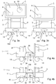
- Fig. 4a and 4b show an embodiment of the braking means 150.
- Fig. 4a shows the braking means 150 in an activated state
- Fig. 4b shows the braking means 150 in a release state.
- the braking means comprise a first rod-shaped actuator 31 which is movably connected to the frame 3 or to the display screen unit 5.
- the actuator 31 is movable essentially in a vertical direction.
- the braking means furthermore comprises a second actuator 33 which is pivotably attached around the axis 32 to the foot unit 11.
- a wire element 34 is suspended between the second actuator 33 and the brake 15 by means of pulley elements 35, 36.
- the wire element 34, the second actuator 33 and the pulleys 35, 36 are positioned in such a way that pivoting of the second actuator 33 results in a movement of the brake 15 toward the wheel element 13, or away from the wheel element 13.
- the pivoting of the second actuator 33 is initiated by the first actuator 31, wherein a downward movement of the first actuator 31 ensures that the brake 15 is moved toward a release state, and an upward movement ensures that the brake 15 is moved toward an activated state.
- the first actuator 31 is configured, in particular, to move downward in response to a downward movement of the display screen unit 5.
- the second actuator 33 is preferably operated by the first actuator 31 only if the display screen unit 5 is close to the first, bottom position, or if it just reaches the first, bottom position.
- Pressing means (not shown, but, for example, in the form of a spring) can be provided to push the second actuator 33 back to the position shown in Fig. 4a so that, when the first actuator 31 moves upward, the braking means 150 are again activated.
- the braking can be performed by means of a pressure contact, as shown in Fig. 3a and 4a , or in any other way, for example by means of a mechanical brake, electrical brake or magnetic brake.
- a drum brake, disc brake or blocking element with interlocking gear teeth can be used. Other types of brakes are obviously conceivable.
- the great advantage of this embodiment is that it improves stability and safety, given that the device can be moved only if the centre of gravity is positioned relatively low. Unwanted falling of the device is thereby prevented.
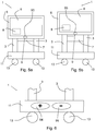
- Fig. 5a thus shows, as an example, a combination of a device 1 with a foot unit with wheel elements, with braking means, wherein the foot unit connects the struts 3 (choice 1); wherein the position-setting means 9 are designed as wireless communication with an activation element 93 (choice b).
- a plurality of choices can, in principle, be made simultaneously. Physical buttons and/or an operation by means of a graphical user interface can thus be provided along with the wireless communication. The person skilled in the art will be able to make a suitable choice.
- FIG. 6 shows a further embodiment of a foot unit 11 for the device 1 according to the present invention, wherein, in particular, foot buttons 94, 95 are provided.
- the foot buttons 94, 95 are connected to the drive means and, if required, to the control unit. With the foot buttons 94, 95, the display screen unit 5 can be positioned incrementally higher ("+”, foot button 94), or incrementally lower ("-", foot button 95). An individual fine adjustment between the first position and the second position is thus possible for the user.
Landscapes
- Engineering & Computer Science (AREA)
- Mechanical Engineering (AREA)
- General Engineering & Computer Science (AREA)
- Devices For Indicating Variable Information By Combining Individual Elements (AREA)
Claims (12)
- Anzeigebildschirmvorrichtung (1), umfassend:- einen Rahmen (3) mit einer Fußeinheit (11) und mehreren damit verbundenen Radelementen (13), wobei die Anzeigebildschirmvorrichtung (1) auf rollende Weise beweglich ist;- eine mit dem Rahmen verbundene Anzeigebildschirmeinheit (5) mit Anzeigebildschirm-Wiedergabemitteln (6), wobei die Anzeigebildschirmeinheit (5) in Bezug auf die Fußeinheit (11) zwischen einer ersten unteren Position und einer zweiten oberen Position höhenverstellbar ist;
dadurch gekennzeichnet, dass die Anzeigebildschirmvorrichtung (1) ferner Bremsmittel (150) zum Bremsen eines oder mehrerer der mehreren Radelemente (13) umfasst, wobei die Bremsmittel (150) so ausgelegt sind, dass das eine oder mehreren der mehreren Radelemente (13) nur freigegeben wird/werden, wenn sich die Anzeigebildschirmeinheit (5) an der ersten unteren Position oder in deren Nähe befindet, so dass die Anzeigebildschirmvorrichtung nur beweglich ist, wenn sich die Anzeigebildschirmeinheit an der ersten unteren Position oder in deren Nähe befindet. - Anzeigebildschirmvorrichtung nach Anspruch 1, wobei die Bremsmittel (150) ein bewegliches Bremselement (15) umfassen, das zum Halten eines oder mehrerer der mehreren Radelemente (13) ausgelegt ist.
- Anzeigebildschirmvorrichtung nach Anspruch 1 oder 2, wobei die Bremsmittel (150) einen ersten Stellantrieb (31) umfassen, der beweglich mit dem Rahmen (3) oder mit der Anzeigebildschirmeinheit (5) verbunden ist und der dafür ausgelegt ist, blockierte Radelemente (13) freizugeben, wenn die Anzeigebildschirmeinheit (5) an die erste untere Position bewegt wird.
- Anzeigebildschirmvorrichtung nach Anspruch 3, wobei die Bremsmittel (150) einen zweiten Stellantrieb (33) umfassen, der mit der Fußeinheit verbunden ist und der zur Interaktion mit dem ersten Stellantrieb (31) ausgelegt ist, um die blockierten Radelemente (13) freizugeben, wenn die Anzeigebildschirmeinheit (5) an die erste untere Position bewegt wird.
- Anzeigebildschirmvorrichtung nach Anspruch 2, 3 und 4, wobei der zweite Stellantrieb (33) funktionsfähig mit dem Bremselement (15) verbunden ist, und wobei, wenn die Anzeigebildschirmeinheit (5) in die Nähe der ersten unteren Position bewegt wird, der erste Stellantrieb (31) zum Schwenken des zweiten Stellantriebs (33) ausgelegt ist, um das Bremselement (15) von dem Radelement weg zu bewegen.
- Anzeigebildschirmvorrichtung (1) nach einem der vorhergehenden Ansprüche, umfassend:- Antriebsmittel (7), die zum Bewegen der Anzeigebildschirmeinheit (5) zwischen der ersten Position und der zweiten Position ausgelegt sind;- eine Steuereinheit (8), die zum Steuern der Antriebsmittel ausgelegt ist; und- Positionseinstellmittel (9), die mit der Steuereinheit (8) verbunden und von einem Benutzer bedienbar sind, wobei die Steuereinheit (8) so ausgelegt ist, dass sie die Antriebsmittel nach der Bedienung der Positionseinstellmittel (9) auf solche Weise steuert, dass die Anzeigebildschirmeinheit an eine vorbestimmte Einstellposition bewegt wird.
- Anzeigebildschirmvorrichtung nach Anspruch 6, wobei die vorbestimmte Einstellposition die erste untere Position ist.
- Anzeigebildschirmvorrichtung nach Anspruch 6 oder 7, wobei die Anzeigebildschirm-Wiedergabemittel (6) zum Anzeigen einer grafischen Benutzeroberfläche (93) ausgelegt sind und wobei die grafische Benutzeroberfläche (93) die Positionseinstellmittel (9) umfasst.
- Anzeigebildschirmvorrichtung nach Anspruch 6, 7 oder 8, wobei die Positionseinstellmittel (9) so ausgelegt sind, dass die Anzeigebildschirmeinheit an mehrere vorbestimmte Einstellpositionen beweglich ist.
- Anzeigebildschirmvorrichtung nach Anspruch 6 bis 9, wobei die Positionseinstellmittel (9) mithilfe drahtloser Kommunikation (92), wie beispielsweise mit NFC, RFID und/oder Bluetooth, bedienbar sind.
- Anzeigebildschirmvorrichtung nach Anspruch 6 bis 10, wobei die vorbestimmte Einstellposition durch einen Benutzer einstellbar ist.
- Anzeigebildschirmvorrichtung nach einem der vorhergehenden Ansprüche, Fußbedienmittel (94, 95) umfassend, die mit der Fußeinheit (11) verbunden und durch einen Benutzer bedienbar sind, und wobei die Anzeigebildschirmeinheit (5) durch einen Benutzer zwischen der ersten Position und der zweiten Position beweglich einstellbar ist.
Applications Claiming Priority (2)
| Application Number | Priority Date | Filing Date | Title |
|---|---|---|---|
| NL2017500A NL2017500B1 (nl) | 2016-09-20 | 2016-09-20 | Beeldscherminrichting |
| PCT/NL2017/050622 WO2018056809A2 (en) | 2016-09-20 | 2017-09-20 | Display screen device |
Publications (2)
| Publication Number | Publication Date |
|---|---|
| EP3516286A2 EP3516286A2 (de) | 2019-07-31 |
| EP3516286B1 true EP3516286B1 (de) | 2020-04-22 |
Family
ID=57104159
Family Applications (1)
| Application Number | Title | Priority Date | Filing Date |
|---|---|---|---|
| EP17787039.1A Active EP3516286B1 (de) | 2016-09-20 | 2017-09-20 | Anzeigebildschirmvorrichtung |
Country Status (3)
| Country | Link |
|---|---|
| EP (1) | EP3516286B1 (de) |
| NL (1) | NL2017500B1 (de) |
| WO (1) | WO2018056809A2 (de) |
Cited By (1)
| Publication number | Priority date | Publication date | Assignee | Title |
|---|---|---|---|---|
| NL2028148B1 (en) | 2021-05-05 | 2022-11-23 | Bordrijk Intellectual Property B V | a screen lift device |
Families Citing this family (4)
| Publication number | Priority date | Publication date | Assignee | Title |
|---|---|---|---|---|
| PL4234240T3 (pl) | 2017-12-22 | 2025-06-23 | Avient Protective Materials B.V. | Arkusz kompozytowy z wysokowydajnych włókien |
| CN110925565A (zh) * | 2019-12-02 | 2020-03-27 | 徐州支点科技有限公司 | 一种技术咨询使用的展示组合装置 |
| CN111503466A (zh) * | 2020-05-19 | 2020-08-07 | 南京舒普医疗科技有限公司 | 渗透式加湿加热电动呼吸机 |
| NL2029225B1 (en) * | 2021-09-22 | 2023-03-29 | Prowise B V | a display screen device |
Family Cites Families (7)
| Publication number | Priority date | Publication date | Assignee | Title |
|---|---|---|---|---|
| DE19918298C2 (de) * | 1999-04-22 | 2001-05-03 | Fette Wilhelm Gmbh | Bedienstand für eine Tablettenpreßvorrichtung |
| DK199900212U3 (da) * | 1999-05-26 | 1999-10-22 | Soeren Rasmussen | Motoriseret rotations- og justerings anordning for f.eks. monitorer |
| KR200386693Y1 (ko) * | 2005-03-24 | 2005-06-16 | 김성삼 | 대형 디스플레이의 승하강 기구 |
| US20070252919A1 (en) * | 2006-04-27 | 2007-11-01 | Mcgreevy Roy L | Remotely controlled adjustable flat panel display support system |
| TWI326437B (en) * | 2006-12-29 | 2010-06-21 | Chimei Innolux Corp | Display device |
| KR101084029B1 (ko) * | 2011-07-19 | 2011-11-16 | (주)엘리비젼 | 자동높이조절 기능이 구비된 키오스크 |
| US9347817B2 (en) * | 2013-03-15 | 2016-05-24 | Surgitrac Corporation | Surgical object and comprehensive fluid monitoring system having capability of mobile monitoring and having highly sensitive and reliable detection of objects being placed in a container |
-
2016
- 2016-09-20 NL NL2017500A patent/NL2017500B1/nl not_active IP Right Cessation
-
2017
- 2017-09-20 WO PCT/NL2017/050622 patent/WO2018056809A2/en not_active Ceased
- 2017-09-20 EP EP17787039.1A patent/EP3516286B1/de active Active
Non-Patent Citations (1)
| Title |
|---|
| None * |
Cited By (1)
| Publication number | Priority date | Publication date | Assignee | Title |
|---|---|---|---|---|
| NL2028148B1 (en) | 2021-05-05 | 2022-11-23 | Bordrijk Intellectual Property B V | a screen lift device |
Also Published As
| Publication number | Publication date |
|---|---|
| EP3516286A2 (de) | 2019-07-31 |
| WO2018056809A3 (en) | 2018-08-02 |
| NL2017500B1 (nl) | 2018-03-29 |
| WO2018056809A2 (en) | 2018-03-29 |
Similar Documents
| Publication | Publication Date | Title |
|---|---|---|
| EP3516286B1 (de) | Anzeigebildschirmvorrichtung | |
| US11656694B2 (en) | Multi-mode scroll wheel for input device | |
| CN106445184B (zh) | 虚拟计算机键盘 | |
| US10037130B2 (en) | Display apparatus and method for improving visibility of the same | |
| US11058216B2 (en) | Control of a height adjustable table using fingerprints | |
| CN106185497B (zh) | 用于通过输入电梯呼叫来启动电梯服务的系统和方法 | |
| EP2249241A1 (de) | Vorrichtung und Verfahren zur Positionierung von Menüpunkten in elliptischen Menüs | |
| WO2013181881A1 (zh) | 触摸屏幕的控制方法及装置 | |
| WO2014073007A1 (en) | Input device, particularly for computers or the like, and corresponding graphical user interface system | |
| JP2012502553A5 (de) | ||
| EP2573648B1 (de) | Taktile Rückmeldungsvorrichtung, System und Verfahren zum Betrieb einer taktilen Rückmeldungsvorrichtung | |
| CN107924282A (zh) | 针对同时作用中应用程序的动态控制方案 | |
| EP2214174A2 (de) | Verfahren und Vorrichtung zur Wiedergabe von Multimedia-Elementen | |
| US9727237B2 (en) | Management method and management system of keypad of handheld electronic device | |
| KR102257772B1 (ko) | 디스플레이 장치 및 그의 제어 방법 | |
| JP2019128942A (ja) | 入力ユニットの持上げ装置及びそのキーボード並びに電子デバイス | |
| KR101812846B1 (ko) | 건설용 리프트의 운행 구간 설정 방법 및 컴퓨터 프로그램 | |
| CN112835670A (zh) | 一种转盘式菜单的实现方法及其存储介质 | |
| JP6695438B2 (ja) | 感圧タッチスクリーン上で複数のオブジェクトを操作するための方法および装置 | |
| CN109564468A (zh) | 信息处理设备、信息处理方法以及程序 | |
| KR20130000786U (ko) | 후면 터치패드와 측면버튼을 이용한 스마트폰 조작방법 | |
| CN107665053B (zh) | 可穿戴式电子设备及适于其的人机交互方法 | |
| JP2024507663A (ja) | コンピュータ、ソフトウェアモジュールアレンジメント、回路アレンジメント、ユーザ装置、および、複数のアプリケーションを同時に制御する改良されたユーザインターフェースのための方法 | |
| KR102378503B1 (ko) | 무형 마우스를 통한 정보의 입출력 방법 및 비일시성의 컴퓨터 판독 가능 기록 매체 | |
| KR20150096171A (ko) | 컨텐츠 처리장치 및 그 메뉴 표시 방법 |
Legal Events
| Date | Code | Title | Description |
|---|---|---|---|
| STAA | Information on the status of an ep patent application or granted ep patent |
Free format text: STATUS: UNKNOWN |
|
| STAA | Information on the status of an ep patent application or granted ep patent |
Free format text: STATUS: THE INTERNATIONAL PUBLICATION HAS BEEN MADE |
|
| PUAI | Public reference made under article 153(3) epc to a published international application that has entered the european phase |
Free format text: ORIGINAL CODE: 0009012 |
|
| STAA | Information on the status of an ep patent application or granted ep patent |
Free format text: STATUS: REQUEST FOR EXAMINATION WAS MADE |
|
| 17P | Request for examination filed |
Effective date: 20190319 |
|
| AK | Designated contracting states |
Kind code of ref document: A2 Designated state(s): AL AT BE BG CH CY CZ DE DK EE ES FI FR GB GR HR HU IE IS IT LI LT LU LV MC MK MT NL NO PL PT RO RS SE SI SK SM TR |
|
| AX | Request for extension of the european patent |
Extension state: BA ME |
|
| DAV | Request for validation of the european patent (deleted) | ||
| DAX | Request for extension of the european patent (deleted) | ||
| GRAP | Despatch of communication of intention to grant a patent |
Free format text: ORIGINAL CODE: EPIDOSNIGR1 |
|
| STAA | Information on the status of an ep patent application or granted ep patent |
Free format text: STATUS: GRANT OF PATENT IS INTENDED |
|
| INTG | Intention to grant announced |
Effective date: 20200211 |
|
| GRAS | Grant fee paid |
Free format text: ORIGINAL CODE: EPIDOSNIGR3 |
|
| GRAA | (expected) grant |
Free format text: ORIGINAL CODE: 0009210 |
|
| STAA | Information on the status of an ep patent application or granted ep patent |
Free format text: STATUS: THE PATENT HAS BEEN GRANTED |
|
| AK | Designated contracting states |
Kind code of ref document: B1 Designated state(s): AL AT BE BG CH CY CZ DE DK EE ES FI FR GB GR HR HU IE IS IT LI LT LU LV MC MK MT NL NO PL PT RO RS SE SI SK SM TR |
|
| REG | Reference to a national code |
Ref country code: CH Ref legal event code: EP |
|
| REG | Reference to a national code |
Ref country code: IE Ref legal event code: FG4D |
|
| REG | Reference to a national code |
Ref country code: DE Ref legal event code: R096 Ref document number: 602017015381 Country of ref document: DE |
|
| REG | Reference to a national code |
Ref country code: AT Ref legal event code: REF Ref document number: 1260575 Country of ref document: AT Kind code of ref document: T Effective date: 20200515 |
|
| REG | Reference to a national code |
Ref country code: NL Ref legal event code: FP |
|
| REG | Reference to a national code |
Ref country code: LT Ref legal event code: MG4D |
|
| PG25 | Lapsed in a contracting state [announced via postgrant information from national office to epo] |
Ref country code: SE Free format text: LAPSE BECAUSE OF FAILURE TO SUBMIT A TRANSLATION OF THE DESCRIPTION OR TO PAY THE FEE WITHIN THE PRESCRIBED TIME-LIMIT Effective date: 20200422 Ref country code: LT Free format text: LAPSE BECAUSE OF FAILURE TO SUBMIT A TRANSLATION OF THE DESCRIPTION OR TO PAY THE FEE WITHIN THE PRESCRIBED TIME-LIMIT Effective date: 20200422 Ref country code: PT Free format text: LAPSE BECAUSE OF FAILURE TO SUBMIT A TRANSLATION OF THE DESCRIPTION OR TO PAY THE FEE WITHIN THE PRESCRIBED TIME-LIMIT Effective date: 20200824 Ref country code: IS Free format text: LAPSE BECAUSE OF FAILURE TO SUBMIT A TRANSLATION OF THE DESCRIPTION OR TO PAY THE FEE WITHIN THE PRESCRIBED TIME-LIMIT Effective date: 20200822 Ref country code: FI Free format text: LAPSE BECAUSE OF FAILURE TO SUBMIT A TRANSLATION OF THE DESCRIPTION OR TO PAY THE FEE WITHIN THE PRESCRIBED TIME-LIMIT Effective date: 20200422 Ref country code: GR Free format text: LAPSE BECAUSE OF FAILURE TO SUBMIT A TRANSLATION OF THE DESCRIPTION OR TO PAY THE FEE WITHIN THE PRESCRIBED TIME-LIMIT Effective date: 20200723 Ref country code: NO Free format text: LAPSE BECAUSE OF FAILURE TO SUBMIT A TRANSLATION OF THE DESCRIPTION OR TO PAY THE FEE WITHIN THE PRESCRIBED TIME-LIMIT Effective date: 20200722 |
|
| REG | Reference to a national code |
Ref country code: AT Ref legal event code: MK05 Ref document number: 1260575 Country of ref document: AT Kind code of ref document: T Effective date: 20200422 |
|
| PG25 | Lapsed in a contracting state [announced via postgrant information from national office to epo] |
Ref country code: RS Free format text: LAPSE BECAUSE OF FAILURE TO SUBMIT A TRANSLATION OF THE DESCRIPTION OR TO PAY THE FEE WITHIN THE PRESCRIBED TIME-LIMIT Effective date: 20200422 Ref country code: BG Free format text: LAPSE BECAUSE OF FAILURE TO SUBMIT A TRANSLATION OF THE DESCRIPTION OR TO PAY THE FEE WITHIN THE PRESCRIBED TIME-LIMIT Effective date: 20200722 Ref country code: HR Free format text: LAPSE BECAUSE OF FAILURE TO SUBMIT A TRANSLATION OF THE DESCRIPTION OR TO PAY THE FEE WITHIN THE PRESCRIBED TIME-LIMIT Effective date: 20200422 Ref country code: LV Free format text: LAPSE BECAUSE OF FAILURE TO SUBMIT A TRANSLATION OF THE DESCRIPTION OR TO PAY THE FEE WITHIN THE PRESCRIBED TIME-LIMIT Effective date: 20200422 |
|
| PG25 | Lapsed in a contracting state [announced via postgrant information from national office to epo] |
Ref country code: AL Free format text: LAPSE BECAUSE OF FAILURE TO SUBMIT A TRANSLATION OF THE DESCRIPTION OR TO PAY THE FEE WITHIN THE PRESCRIBED TIME-LIMIT Effective date: 20200422 |
|
| REG | Reference to a national code |
Ref country code: DE Ref legal event code: R097 Ref document number: 602017015381 Country of ref document: DE |
|
| PG25 | Lapsed in a contracting state [announced via postgrant information from national office to epo] |
Ref country code: RO Free format text: LAPSE BECAUSE OF FAILURE TO SUBMIT A TRANSLATION OF THE DESCRIPTION OR TO PAY THE FEE WITHIN THE PRESCRIBED TIME-LIMIT Effective date: 20200422 Ref country code: IT Free format text: LAPSE BECAUSE OF FAILURE TO SUBMIT A TRANSLATION OF THE DESCRIPTION OR TO PAY THE FEE WITHIN THE PRESCRIBED TIME-LIMIT Effective date: 20200422 Ref country code: CZ Free format text: LAPSE BECAUSE OF FAILURE TO SUBMIT A TRANSLATION OF THE DESCRIPTION OR TO PAY THE FEE WITHIN THE PRESCRIBED TIME-LIMIT Effective date: 20200422 Ref country code: EE Free format text: LAPSE BECAUSE OF FAILURE TO SUBMIT A TRANSLATION OF THE DESCRIPTION OR TO PAY THE FEE WITHIN THE PRESCRIBED TIME-LIMIT Effective date: 20200422 Ref country code: SM Free format text: LAPSE BECAUSE OF FAILURE TO SUBMIT A TRANSLATION OF THE DESCRIPTION OR TO PAY THE FEE WITHIN THE PRESCRIBED TIME-LIMIT Effective date: 20200422 Ref country code: AT Free format text: LAPSE BECAUSE OF FAILURE TO SUBMIT A TRANSLATION OF THE DESCRIPTION OR TO PAY THE FEE WITHIN THE PRESCRIBED TIME-LIMIT Effective date: 20200422 Ref country code: ES Free format text: LAPSE BECAUSE OF FAILURE TO SUBMIT A TRANSLATION OF THE DESCRIPTION OR TO PAY THE FEE WITHIN THE PRESCRIBED TIME-LIMIT Effective date: 20200422 Ref country code: DK Free format text: LAPSE BECAUSE OF FAILURE TO SUBMIT A TRANSLATION OF THE DESCRIPTION OR TO PAY THE FEE WITHIN THE PRESCRIBED TIME-LIMIT Effective date: 20200422 |
|
| PG25 | Lapsed in a contracting state [announced via postgrant information from national office to epo] |
Ref country code: SK Free format text: LAPSE BECAUSE OF FAILURE TO SUBMIT A TRANSLATION OF THE DESCRIPTION OR TO PAY THE FEE WITHIN THE PRESCRIBED TIME-LIMIT Effective date: 20200422 Ref country code: PL Free format text: LAPSE BECAUSE OF FAILURE TO SUBMIT A TRANSLATION OF THE DESCRIPTION OR TO PAY THE FEE WITHIN THE PRESCRIBED TIME-LIMIT Effective date: 20200422 |
|
| PLBE | No opposition filed within time limit |
Free format text: ORIGINAL CODE: 0009261 |
|
| STAA | Information on the status of an ep patent application or granted ep patent |
Free format text: STATUS: NO OPPOSITION FILED WITHIN TIME LIMIT |
|
| 26N | No opposition filed |
Effective date: 20210125 |
|
| REG | Reference to a national code |
Ref country code: CH Ref legal event code: PL |
|
| PG25 | Lapsed in a contracting state [announced via postgrant information from national office to epo] |
Ref country code: LU Free format text: LAPSE BECAUSE OF NON-PAYMENT OF DUE FEES Effective date: 20200920 |
|
| PG25 | Lapsed in a contracting state [announced via postgrant information from national office to epo] |
Ref country code: CH Free format text: LAPSE BECAUSE OF NON-PAYMENT OF DUE FEES Effective date: 20200930 Ref country code: LI Free format text: LAPSE BECAUSE OF NON-PAYMENT OF DUE FEES Effective date: 20200930 Ref country code: IE Free format text: LAPSE BECAUSE OF NON-PAYMENT OF DUE FEES Effective date: 20200920 |
|
| PG25 | Lapsed in a contracting state [announced via postgrant information from national office to epo] |
Ref country code: TR Free format text: LAPSE BECAUSE OF FAILURE TO SUBMIT A TRANSLATION OF THE DESCRIPTION OR TO PAY THE FEE WITHIN THE PRESCRIBED TIME-LIMIT Effective date: 20200422 Ref country code: MT Free format text: LAPSE BECAUSE OF FAILURE TO SUBMIT A TRANSLATION OF THE DESCRIPTION OR TO PAY THE FEE WITHIN THE PRESCRIBED TIME-LIMIT Effective date: 20200422 Ref country code: CY Free format text: LAPSE BECAUSE OF FAILURE TO SUBMIT A TRANSLATION OF THE DESCRIPTION OR TO PAY THE FEE WITHIN THE PRESCRIBED TIME-LIMIT Effective date: 20200422 |
|
| PG25 | Lapsed in a contracting state [announced via postgrant information from national office to epo] |
Ref country code: MK Free format text: LAPSE BECAUSE OF FAILURE TO SUBMIT A TRANSLATION OF THE DESCRIPTION OR TO PAY THE FEE WITHIN THE PRESCRIBED TIME-LIMIT Effective date: 20200422 Ref country code: MC Free format text: LAPSE BECAUSE OF FAILURE TO SUBMIT A TRANSLATION OF THE DESCRIPTION OR TO PAY THE FEE WITHIN THE PRESCRIBED TIME-LIMIT Effective date: 20200422 |
|
| P01 | Opt-out of the competence of the unified patent court (upc) registered |
Effective date: 20230527 |
|
| PG25 | Lapsed in a contracting state [announced via postgrant information from national office to epo] |
Ref country code: SI Free format text: LAPSE BECAUSE OF FAILURE TO SUBMIT A TRANSLATION OF THE DESCRIPTION OR TO PAY THE FEE WITHIN THE PRESCRIBED TIME-LIMIT Effective date: 20200422 |
|
| PGFP | Annual fee paid to national office [announced via postgrant information from national office to epo] |
Ref country code: DE Payment date: 20250919 Year of fee payment: 9 |
|
| PGFP | Annual fee paid to national office [announced via postgrant information from national office to epo] |
Ref country code: NL Payment date: 20250918 Year of fee payment: 9 |
|
| PGFP | Annual fee paid to national office [announced via postgrant information from national office to epo] |
Ref country code: BE Payment date: 20250918 Year of fee payment: 9 Ref country code: GB Payment date: 20250919 Year of fee payment: 9 |
|
| PGFP | Annual fee paid to national office [announced via postgrant information from national office to epo] |
Ref country code: FR Payment date: 20250922 Year of fee payment: 9 |