EP3515779B1 - Verfahren zur überwachung einer elektromagnetisch betätigbaren bremse und fahrzeug mit elektromagnetisch betätigbarer bremse - Google Patents
Verfahren zur überwachung einer elektromagnetisch betätigbaren bremse und fahrzeug mit elektromagnetisch betätigbarer bremse Download PDFInfo
- Publication number
- EP3515779B1 EP3515779B1 EP17745261.2A EP17745261A EP3515779B1 EP 3515779 B1 EP3515779 B1 EP 3515779B1 EP 17745261 A EP17745261 A EP 17745261A EP 3515779 B1 EP3515779 B1 EP 3515779B1
- Authority
- EP
- European Patent Office
- Prior art keywords
- brake
- coil
- current
- determined
- state
- Prior art date
- Legal status (The legal status is an assumption and is not a legal conclusion. Google has not performed a legal analysis and makes no representation as to the accuracy of the status listed.)
- Active
Links
Images
Classifications
-
- B—PERFORMING OPERATIONS; TRANSPORTING
- B60—VEHICLES IN GENERAL
- B60T—VEHICLE BRAKE CONTROL SYSTEMS OR PARTS THEREOF; BRAKE CONTROL SYSTEMS OR PARTS THEREOF, IN GENERAL; ARRANGEMENT OF BRAKING ELEMENTS ON VEHICLES IN GENERAL; PORTABLE DEVICES FOR PREVENTING UNWANTED MOVEMENT OF VEHICLES; VEHICLE MODIFICATIONS TO FACILITATE COOLING OF BRAKES
- B60T17/00—Component parts, details, or accessories of power brake systems not covered by groups B60T8/00, B60T13/00 or B60T15/00, or presenting other characteristic features
- B60T17/18—Safety devices; Monitoring
- B60T17/22—Devices for monitoring or checking brake systems; Signal devices
-
- B—PERFORMING OPERATIONS; TRANSPORTING
- B60—VEHICLES IN GENERAL
- B60T—VEHICLE BRAKE CONTROL SYSTEMS OR PARTS THEREOF; BRAKE CONTROL SYSTEMS OR PARTS THEREOF, IN GENERAL; ARRANGEMENT OF BRAKING ELEMENTS ON VEHICLES IN GENERAL; PORTABLE DEVICES FOR PREVENTING UNWANTED MOVEMENT OF VEHICLES; VEHICLE MODIFICATIONS TO FACILITATE COOLING OF BRAKES
- B60T17/00—Component parts, details, or accessories of power brake systems not covered by groups B60T8/00, B60T13/00 or B60T15/00, or presenting other characteristic features
- B60T17/18—Safety devices; Monitoring
- B60T17/22—Devices for monitoring or checking brake systems; Signal devices
- B60T17/221—Procedure or apparatus for checking or keeping in a correct functioning condition of brake systems
-
- B—PERFORMING OPERATIONS; TRANSPORTING
- B60—VEHICLES IN GENERAL
- B60B—VEHICLE WHEELS; CASTORS; AXLES FOR WHEELS OR CASTORS; INCREASING WHEEL ADHESION
- B60B33/00—Castors in general ; Anti-clogging castors
- B60B33/0078—Castors in general ; Anti-clogging castors characterised by details of the wheel braking mechanism
- B60B33/0092—Castors in general ; Anti-clogging castors characterised by details of the wheel braking mechanism actuated remotely, e.g. by cable or electrically
-
- B—PERFORMING OPERATIONS; TRANSPORTING
- B60—VEHICLES IN GENERAL
- B60T—VEHICLE BRAKE CONTROL SYSTEMS OR PARTS THEREOF; BRAKE CONTROL SYSTEMS OR PARTS THEREOF, IN GENERAL; ARRANGEMENT OF BRAKING ELEMENTS ON VEHICLES IN GENERAL; PORTABLE DEVICES FOR PREVENTING UNWANTED MOVEMENT OF VEHICLES; VEHICLE MODIFICATIONS TO FACILITATE COOLING OF BRAKES
- B60T13/00—Transmitting braking action from initiating means to ultimate brake actuator with power assistance or drive; Brake systems incorporating such transmitting means, e.g. air-pressure brake systems
- B60T13/74—Transmitting braking action from initiating means to ultimate brake actuator with power assistance or drive; Brake systems incorporating such transmitting means, e.g. air-pressure brake systems with electrical assistance or drive
- B60T13/748—Transmitting braking action from initiating means to ultimate brake actuator with power assistance or drive; Brake systems incorporating such transmitting means, e.g. air-pressure brake systems with electrical assistance or drive acting on electro-magnetic brakes
-
- B—PERFORMING OPERATIONS; TRANSPORTING
- B60—VEHICLES IN GENERAL
- B60T—VEHICLE BRAKE CONTROL SYSTEMS OR PARTS THEREOF; BRAKE CONTROL SYSTEMS OR PARTS THEREOF, IN GENERAL; ARRANGEMENT OF BRAKING ELEMENTS ON VEHICLES IN GENERAL; PORTABLE DEVICES FOR PREVENTING UNWANTED MOVEMENT OF VEHICLES; VEHICLE MODIFICATIONS TO FACILITATE COOLING OF BRAKES
- B60T8/00—Arrangements for adjusting wheel-braking force to meet varying vehicular or ground-surface conditions, e.g. limiting or varying distribution of braking force
- B60T8/32—Arrangements for adjusting wheel-braking force to meet varying vehicular or ground-surface conditions, e.g. limiting or varying distribution of braking force responsive to a speed condition, e.g. acceleration or deceleration
- B60T8/88—Arrangements for adjusting wheel-braking force to meet varying vehicular or ground-surface conditions, e.g. limiting or varying distribution of braking force responsive to a speed condition, e.g. acceleration or deceleration with failure responsive means, i.e. means for detecting and indicating faulty operation of the speed responsive control means
- B60T8/885—Arrangements for adjusting wheel-braking force to meet varying vehicular or ground-surface conditions, e.g. limiting or varying distribution of braking force responsive to a speed condition, e.g. acceleration or deceleration with failure responsive means, i.e. means for detecting and indicating faulty operation of the speed responsive control means using electrical circuitry
-
- B—PERFORMING OPERATIONS; TRANSPORTING
- B62—LAND VEHICLES FOR TRAVELLING OTHERWISE THAN ON RAILS
- B62B—HAND-PROPELLED VEHICLES, e.g. HAND CARTS OR PERAMBULATORS; SLEDGES
- B62B3/00—Hand carts having more than one axis carrying transport wheels; Steering devices therefor; Equipment therefor
-
- B—PERFORMING OPERATIONS; TRANSPORTING
- B62—LAND VEHICLES FOR TRAVELLING OTHERWISE THAN ON RAILS
- B62B—HAND-PROPELLED VEHICLES, e.g. HAND CARTS OR PERAMBULATORS; SLEDGES
- B62B5/00—Accessories or details specially adapted for hand carts
- B62B5/04—Braking mechanisms; Locking devices against movement
- B62B5/048—Hub brakes; drum brakes
-
- F—MECHANICAL ENGINEERING; LIGHTING; HEATING; WEAPONS; BLASTING
- F16—ENGINEERING ELEMENTS AND UNITS; GENERAL MEASURES FOR PRODUCING AND MAINTAINING EFFECTIVE FUNCTIONING OF MACHINES OR INSTALLATIONS; THERMAL INSULATION IN GENERAL
- F16D—COUPLINGS FOR TRANSMITTING ROTATION; CLUTCHES; BRAKES
- F16D49/00—Brakes with a braking member co-operating with the periphery of a drum, wheel-rim, or the like
-
- F—MECHANICAL ENGINEERING; LIGHTING; HEATING; WEAPONS; BLASTING
- F16—ENGINEERING ELEMENTS AND UNITS; GENERAL MEASURES FOR PRODUCING AND MAINTAINING EFFECTIVE FUNCTIONING OF MACHINES OR INSTALLATIONS; THERMAL INSULATION IN GENERAL
- F16D—COUPLINGS FOR TRANSMITTING ROTATION; CLUTCHES; BRAKES
- F16D63/00—Brakes not otherwise provided for; Brakes combining more than one of the types of groups F16D49/00 - F16D61/00
- F16D63/002—Brakes with direct electrical or electro-magnetic actuation
-
- F—MECHANICAL ENGINEERING; LIGHTING; HEATING; WEAPONS; BLASTING
- F16—ENGINEERING ELEMENTS AND UNITS; GENERAL MEASURES FOR PRODUCING AND MAINTAINING EFFECTIVE FUNCTIONING OF MACHINES OR INSTALLATIONS; THERMAL INSULATION IN GENERAL
- F16D—COUPLINGS FOR TRANSMITTING ROTATION; CLUTCHES; BRAKES
- F16D65/00—Parts or details
- F16D65/14—Actuating mechanisms for brakes; Means for initiating operation at a predetermined position
- F16D65/16—Actuating mechanisms for brakes; Means for initiating operation at a predetermined position arranged in or on the brake
-
- F—MECHANICAL ENGINEERING; LIGHTING; HEATING; WEAPONS; BLASTING
- F16—ENGINEERING ELEMENTS AND UNITS; GENERAL MEASURES FOR PRODUCING AND MAINTAINING EFFECTIVE FUNCTIONING OF MACHINES OR INSTALLATIONS; THERMAL INSULATION IN GENERAL
- F16D—COUPLINGS FOR TRANSMITTING ROTATION; CLUTCHES; BRAKES
- F16D66/00—Arrangements for monitoring working conditions, e.g. wear, temperature
- F16D66/02—Apparatus for indicating wear
- F16D66/021—Apparatus for indicating wear using electrical detection or indication means
-
- B—PERFORMING OPERATIONS; TRANSPORTING
- B60—VEHICLES IN GENERAL
- B60B—VEHICLE WHEELS; CASTORS; AXLES FOR WHEELS OR CASTORS; INCREASING WHEEL ADHESION
- B60B2900/00—Purpose of invention
- B60B2900/50—Improvement of
-
- B—PERFORMING OPERATIONS; TRANSPORTING
- B60—VEHICLES IN GENERAL
- B60B—VEHICLE WHEELS; CASTORS; AXLES FOR WHEELS OR CASTORS; INCREASING WHEEL ADHESION
- B60B33/00—Castors in general ; Anti-clogging castors
- B60B33/0047—Castors in general ; Anti-clogging castors characterised by details of the rolling axle
- B60B33/0049—Castors in general ; Anti-clogging castors characterised by details of the rolling axle the rolling axle being horizontal
-
- B—PERFORMING OPERATIONS; TRANSPORTING
- B60—VEHICLES IN GENERAL
- B60B—VEHICLE WHEELS; CASTORS; AXLES FOR WHEELS OR CASTORS; INCREASING WHEEL ADHESION
- B60B33/00—Castors in general ; Anti-clogging castors
- B60B33/0047—Castors in general ; Anti-clogging castors characterised by details of the rolling axle
- B60B33/0057—Castors in general ; Anti-clogging castors characterised by details of the rolling axle the rolling axle being offset from swivel axis
-
- B—PERFORMING OPERATIONS; TRANSPORTING
- B60—VEHICLES IN GENERAL
- B60B—VEHICLE WHEELS; CASTORS; AXLES FOR WHEELS OR CASTORS; INCREASING WHEEL ADHESION
- B60B33/00—Castors in general ; Anti-clogging castors
- B60B33/006—Castors in general ; Anti-clogging castors characterised by details of the swivel mechanism
- B60B33/0065—Castors in general ; Anti-clogging castors characterised by details of the swivel mechanism characterised by details of the swivel axis
- B60B33/0068—Castors in general ; Anti-clogging castors characterised by details of the swivel mechanism characterised by details of the swivel axis the swivel axis being vertical
-
- B—PERFORMING OPERATIONS; TRANSPORTING
- B60—VEHICLES IN GENERAL
- B60B—VEHICLE WHEELS; CASTORS; AXLES FOR WHEELS OR CASTORS; INCREASING WHEEL ADHESION
- B60B33/00—Castors in general ; Anti-clogging castors
- B60B33/0078—Castors in general ; Anti-clogging castors characterised by details of the wheel braking mechanism
-
- B—PERFORMING OPERATIONS; TRANSPORTING
- B60—VEHICLES IN GENERAL
- B60T—VEHICLE BRAKE CONTROL SYSTEMS OR PARTS THEREOF; BRAKE CONTROL SYSTEMS OR PARTS THEREOF, IN GENERAL; ARRANGEMENT OF BRAKING ELEMENTS ON VEHICLES IN GENERAL; PORTABLE DEVICES FOR PREVENTING UNWANTED MOVEMENT OF VEHICLES; VEHICLE MODIFICATIONS TO FACILITATE COOLING OF BRAKES
- B60T2270/00—Further aspects of brake control systems not otherwise provided for
- B60T2270/40—Failsafe aspects of brake control systems
- B60T2270/406—Test-mode; Self-diagnosis
-
- B—PERFORMING OPERATIONS; TRANSPORTING
- B62—LAND VEHICLES FOR TRAVELLING OTHERWISE THAN ON RAILS
- B62B—HAND-PROPELLED VEHICLES, e.g. HAND CARTS OR PERAMBULATORS; SLEDGES
- B62B2301/00—Wheel arrangements; Steering; Stability; Wheel suspension
- B62B2301/04—Wheel arrangements; Steering; Stability; Wheel suspension comprising a wheel pivotable about a substantially vertical axis, e.g. swivelling castors
-
- F—MECHANICAL ENGINEERING; LIGHTING; HEATING; WEAPONS; BLASTING
- F16—ENGINEERING ELEMENTS AND UNITS; GENERAL MEASURES FOR PRODUCING AND MAINTAINING EFFECTIVE FUNCTIONING OF MACHINES OR INSTALLATIONS; THERMAL INSULATION IN GENERAL
- F16D—COUPLINGS FOR TRANSMITTING ROTATION; CLUTCHES; BRAKES
- F16D2121/00—Type of actuator operation force
- F16D2121/18—Electric or magnetic
- F16D2121/20—Electric or magnetic using electromagnets
- F16D2121/22—Electric or magnetic using electromagnets for releasing a normally applied brake
-
- F—MECHANICAL ENGINEERING; LIGHTING; HEATING; WEAPONS; BLASTING
- F16—ENGINEERING ELEMENTS AND UNITS; GENERAL MEASURES FOR PRODUCING AND MAINTAINING EFFECTIVE FUNCTIONING OF MACHINES OR INSTALLATIONS; THERMAL INSULATION IN GENERAL
- F16D—COUPLINGS FOR TRANSMITTING ROTATION; CLUTCHES; BRAKES
- F16D2125/00—Components of actuators
- F16D2125/18—Mechanical mechanisms
- F16D2125/20—Mechanical mechanisms converting rotation to linear movement or vice versa
- F16D2125/22—Mechanical mechanisms converting rotation to linear movement or vice versa acting transversely to the axis of rotation
- F16D2125/28—Cams; Levers with cams
Definitions
- the invention relates to a method for monitoring an electromagnetically actuated brake and a vehicle with an electromagnetically actuated brake.
- a brake has a coil, which, when energized, can generate a magnetic field that is intended for electromagnetic actuation.
- the brake can be released or applied by energizing or not energizing it.
- the invention is therefore based on the object of further developing, and in particular improving, the operation of a vehicle with brakes.
- the object is achieved in the method according to the features specified in claim 1 and in the vehicle according to the features specified in claim 4.
- the advantage here is that the current curve is monitored and/or evaluated.
- the brake coil is used as a sensor.
- the position of the solenoid is determined from the current curve and thus, for example, the wear of the brake pad, an unacceptably large deviation from the intended operating behavior when releasing or applying the brake, i.e. opening or closing the brake.
- the wear state of a brake pad of the brake is determined from the specific position, wherein a brake pad carrier can be pressed by a spring element of the brake by means of the lifting magnet against a part having a braking surface, in particular a brake drum, to generate a frictional torque, in particular when the coil is de-energized.
- the advantage here is that the state of wear, i.e. the degree of wear, of the brake pad can be determined in a simple manner. This is because with increasing wear, i.e. increasing degree of wear, the brake pad becomes thinner and the position of the lifting magnet in the collapsed state shifts accordingly.
- the opening force of the brake is determined from the current curve recorded when the brake is released, i.e. the current curve recorded when the brake state changes from the applied to the released state of the brake and monitored for exceeding a first threshold value and/or falling below a second threshold value, in particular for displaying and/or forwarding a warning and/or error message, and/or triggering an action.
- condition monitoring and/or function monitoring can be carried out in a simple manner.
- a risk can be identified by determining the change accordingly, such as the degree of wear of a functionally necessary part, and can be displayed and/or reported as a warning or error message.
- the duration of the opening process, in particular the release process, of the brake is determined from the time interval between two consecutive extremes, in particular extreme ranges.
- the ohmic resistance of the coil is determined from the voltage applied to the coil and the current flowing through the coil, in particular when the brake is in an operating state with a constant current value, and the temperature of the brake is determined from this.
- the brake when the brake is in an operating state with a substantially constant current value of the current flowing through the coil, the detected current value is monitored for exceeding a first threshold value and/or falling below a second threshold value and, depending on this, a warning is displayed and/or reported via a bus system.
- a first threshold value and/or falling below a second threshold value when the brake is in an operating state with a substantially constant current value of the current flowing through the coil, the detected current value is monitored for exceeding a first threshold value and/or falling below a second threshold value and, depending on this, a warning is displayed and/or reported via a bus system.
- the current value of the current flowing through the coil is recorded when the coil is permanently ventilated and is monitored for unacceptably high deviations and, depending on this, a warning is displayed and/or reported via a data bus.
- the advantage here is that the condition of the brake can be monitored in a simple manner. Only the described current value and, if applicable, the value of the voltage applied to the coil must be determined.
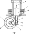
- the wheel unit has a wheel 1 to which a brake drum 2 is connected and arranged in a rotationally fixed manner.
- the brake drum 2 thus represents a braking surface against which a brake pad can be pressed to generate a friction torque.
- the brake pad is arranged on a brake pad carrier (3, 4) which is rotatably mounted on a supporting part of the wheel unit
- the brake pad carrier is shown in a first rotational position 3 and in a second rotational position 4.
- the released and applied state of the brake is visibly shown.
- a coil 5 is arranged on the wheel unit, which when energized pushes a linearly movable lifting magnet 7 with a tappet section 9, which is guided in particular on the linear guide 8, out of the coil as a result of the repulsive force generated by the magnetic field of the coil 5, which overcomes the spring force of a spring element.
- the tappet section 9 is thus pushed away from the brake pad carrier (3, 4) and the brake is thereby released, i.e. released.
- the wheel unit is rotatably mounted on a frame of a vehicle via a bearing 6.
- the vehicle preferably has two or more such wheel units rotatably mounted on the frame of the vehicle.
- the lifting magnet 7 When the coil 5 is de-energized, the lifting magnet 7 is pressed by the spring element towards the coil 5, so that the plunger section 9 presses on the brake pad carrier (3, 4) in such a way that the brake is applied, i.e. the brake pad of the brake pad carrier is pressed against the brake drum 2.
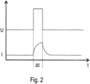
- the voltage effective for permanently releasing the brake is briefly increased to determine the stroke position. During this time, the current increases.
- the linear position of the lifting magnet 7 relative to the coil 5 can be determined from the associated current curve, in particular by determining the differential inductance. This is because the inductance of the coil 5 decreases as the working air gap of the brake increases.
- the determination is carried out in an evaluation unit, which is fed with the current value curve of the current of the coil 5, recorded by a current sensor, and by which the voltage applied to the coil 5 can be controlled.
- the position of the lifting magnet 7 relative to the coil 5 can thus be determined from the current response to the voltage increase pulse by determining the differential inductance.
- the evaluation unit can therefore determine the state of the brake based on the determined position. This then recognizes from the determined position whether the brake is in the released or applied state. In the released state, the brake does not generate any friction torque, but in the applied state, the brake generates friction torque.
- the evaluation unit can even determine the degree of wear on the brake pad from a specific position. If a threshold value is undershot, a warning can be displayed and/or reported. When the brake is applied, the air gap increases as the brake pad wears and the position of the lifting magnet 7 is shifted accordingly.
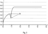
- the current through the coil 5 increases when the brake is opened because a corresponding voltage is effective at the coil 5.
- the magnetic field generated by the coil 5 exerts such a large force on the lifting magnet 7 that, after overcoming the static friction, the lifting magnet 7 begins to move and thus the air gap increases, the current collapses as a result of the decreasing inductance and, after the collapse, rises at a rate corresponding to the reduced inductance.
- the force required to release the brake can be determined from the extreme ranges 30 of the current curve determined by the evaluation unit through current detection and evaluation of the detected current value curve, i.e. the highest value before the collapse and the minimum value reached during the collapse.
- the time until the brake is released can be monitored by the evaluation unit, whereby it is monitored whether the time exceeds a threshold value and/or falls below another threshold value. In this way, the function of the brake can be monitored during operation. This means that a brake function that deviates from the desired function can be detected and a corresponding warning can be displayed or transmitted.
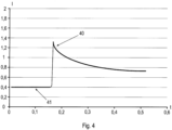
- a preset current value is necessary. This holding current 41 can be monitored by the evaluation unit so that an unwanted change to the applied state of the brake can be detected. This is because, as in Figure 4 As shown, a current increase 40 is the result. Thus, if the current exceeds a threshold value, this is a sign of an unwanted application of the brake.
- the recorded current value is monitored for impermissible deviations from a specified value and in this way the evaluation unit issues a warning or an error is displayed, in particular such as a line break, line short circuit, or unwanted change in the brake state.
- the evaluation unit determines the ohmic resistance of the coil from the voltage applied to coil 5 and the current detected.
- the temperature value of coil 5 is then determined from the resistance value determined in this way using a characteristic curve or parameters stored in the evaluation unit and monitored for exceeding a threshold value, so that even in the event of excess temperature, a corresponding warning can be displayed and/or forwarded to other bus participants via the data bus.
Landscapes
- Engineering & Computer Science (AREA)
- Mechanical Engineering (AREA)
- Transportation (AREA)
- General Engineering & Computer Science (AREA)
- Chemical & Material Sciences (AREA)
- Combustion & Propulsion (AREA)
- Braking Arrangements (AREA)
- Valves And Accessory Devices For Braking Systems (AREA)
Description
- Die Erfindung betrifft ein Verfahren zur Überwachung einer elektromagnetisch betätigbaren Bremse und Fahrzeug mit elektromagnetisch betätigbarer Bremse.
- Es ist allgemein bekannt, dass eine Bremse eine Spule aufweist, durch deren Bestromung ein Magnetfeld erzeugbar ist, welches zur elektromagnetischen Betätigung vorgesehen ist. Mittels Bestromung oder Nicht-Bestromung ist das Lüften oder Einfallen der Bremse bewirkbar.
- So ist aus der
DE 10 2013 018 272 A1 ein Verfahren zum Überwachen des Zustands einer Bremse eines Mobilteils bekannt. - Aus der
DE 10 2012 008 547 B3 ist ein Verfahren zum Überwachen einer Bremse bekannt. - Aus der
DE 10 2012 005 862 A1 ist ein Verfahren zur Wirküberwachung von Schienenbremsen bekannt. - Aus der
DE 11 2012 005188 T5 ist als nächstliegender Stand der Technik ist eine Diagnosevorrichtung des Bremsenzustands für elektromagnetische Bremse bekannt. - Aus der
EP 2 930 504 A2 ist ein Sensorsystem zur Zustandserkennung bekannt. - Aus der
DE 195 48 520 A1 ist ein Verfahren zum Ermitteln der Luftspaltdicke einer Kupplung bekannt. - Aus der
DE 101 49 604 A1 ist ein Verfahren zur Überwachung des Betriebszustandes einer elektromagnetisch betätigbaren Bremse bekannt. - Aus der
DE 10 2004 015447 A1 ist ein Verfahren zum Notbetrieb eines hydraulischen Bremssystems für Kraftfahrzeuge bekannt. - Aus der
JP H08 42613 A - Aus der
US 2003/061872 A1 ist ein Verfahren zur Verschleißbestimmung einer Bremse bekannt. - Aus der
DE 10 2008 029 312 B3 ist ein Verfahren zur Wirküberwachung einer Schienenbremse bekannt. - Der Erfindung liegt daher die Aufgabe zugrunde, das Betreiben eines Fahrzeugs mit Bremse weiterzubilden, insbesondere zu verbessern.
- Erfindungsgemäß wird die Aufgabe bei dem Verfahren nach den in Anspruch 1 und bei dem Fahrzeug nach den in Anspruch 4 angegebenen Merkmalen gelöst.
- Wichtige Merkmale der Erfindung bei dem Verfahren zur Überwachung einer elektromagnetisch betätigbaren Bremse, welche eine mit einem linear bewegbar angeordneten Hubmagneten zusammenwirkende bestrombare Spule aufweist, sind, dass der durch die Spule fließende Strom erfasst wird, insbesondere wobei der erfasste Stromwert einer Auswerteeinheit zugeführt wird,
- wobei zeitabschnittsweise die an der Spule angelegte Spannung erhöht wird und aus dem dadurch bewirkten Stromverlauf, insbesondere Verlauf des Stromanstiegs, eine auf die Spule bezogene relative Position des Hubmagneten bestimmt wird,
- wobei aus der bestimmten Position bestimmt wird, ob die Bremse im eingefallenen Zustand oder im gelüfteten Zustand ist,
- wobei der Hubmagnet als Dauermagnet ausgeführt ist oder einen Dauermagneten aufweist.
- Von Vorteil ist dabei, dass der Stromverlauf überwacht und/oder ausgewertet wird. Durch die Verwendung des Stromverlaufs wird die Spule der Bremse als Sensor verwendet. Somit wird aus dem Stromverlauf die Position des Hubmagneten bestimmt und somit beispielsweise die Abnutzung des Bremsbelags, eine unzulässig große Abweichung vom vorgesehenen Betriebsverhalten beim Lüften oder Einfallen der Bremse, also Öffnen beziehungsweise Schließen der Bremse.
- Erfindungsgemäß wird im eingefallenen Zustand, also bei von Null beginnendem Stromverlauf, aus der bestimmten Position der Verschleißzustand eines Bremsbelags der Bremse bestimmt,
wobei von einem Federelement der Bremse mittels des Hubmagneten ein Bremsbelagträger gegen ein eine Bremsfläche aufweisendes Teil, insbesondere Bremstrommel, zur Erzeugung eines Reibmomentes drückbar ist, insbesondere bei stromloser Spule gedrückt ist. Von Vorteil ist dabei, dass der Verschleißzustand, also der Abnutzungsgrad, des Bremsbelags in einfacher weise bestimmbar ist. Denn bei zunehmendem Verschleiß, also zunehmendem Abnutzungsgrad, wird der Bremsbelag dünnschichtiger und die Position des Hubmagneten beim eingefallenen Zustand verschiebt sich entsprechend. - Erfindungsgemäß wird aus dem beim Lüften der Bremse, also der zum Wechsel des Zustandes der Bremse vom eingefallenen zum gelüfteten Zustand der Bremse, erfasste Stromverlauf die Öffnungskraft der Bremse bestimmt
und auf Überschreiten eines ersten Schwellwertes und/oder Unterschreiten eines zweiten Schwellwertes überwacht, insbesondere zum Anzeigen und/oder Weiterleiten einer Warnung und/oder Fehlermeldung, und/oder Auslösen einer Aktion. Von Vorteil ist dabei, dass eine Zustandsüberwachung und/oder Funktionsüberwachung in einfacher Weise ausführbar ist. Dabei ist durch die Bestimmung der Dauer des Öffnungsvorgangs, also der Zeitabstand zwischen Lösen des Bremsbelags von der Bremsfläche an der Bremstrommel der Bremse und dem Erreichen der von der Spule aus gesehen entferntesten Position des Hubmagneten, eine Überwachung des Wirkungspfades der Bremse ermöglicht. Versagt eines der für diese Wirkung notwendigen Teile der Bremse oder verschleißt eines der Teile derart, dass davon abhängig eine Verschiebung der Positionen und/oder eine Veränderung der Zeitdauer des Öffnungsvorgangs bewirkbar ist, ist durch die entsprechende Bestimmung der Veränderung, wie beispielsweise Abnutzungsgrad eines funktionsnotwendigen Teils, ein Risiko erkennbar und als Warnung oder Fehlermeldung anzeigbar und/oder weitermeldbar. - Erfindungsgemäß werden lokale Extrema des beim Lüften der Bremse erfassten Stromverlaufs bestimmt und aus dem zeitlichen Abstand zweier aufeinander folgender Extrema, insbesondere Extremalbereiche, wird die Dauer des Öffnungsvorgangs, insbesondere Lüftvorgangs, der Bremse bestimmt. Von Vorteil ist dabei, dass die Zeitdauer in einfacher Weise bestimmbar ist.
- Erfindungsgemäß wird aus der an der Spule anliegenden Spannung und dem durch die Spule fließenden Strom, insbesondere bei einem Betriebszustand der Bremse mit konstantem Strombetragswert, der Ohm'sche Widerstand der Spule bestimmt und daraus wird die Temperatur der Bremse bestimmt. Von Vorteil ist dabei, dass diese Bestimmungen jeweils in einfacher Weise ausführbar sind, also nur das Bestimmen von Werten elektrisch detektierbarer physikalischer Größen notwendig ist.
- Bei einer vorteilhaften Ausgestaltung wird bei einem Betriebszustand der Bremse bei einem im Wesentlichen konstanten Strombetragswert des die Spule durchfließenden Stroms der erfasste Stromwert auf Überschreiten eines ersten Schwellwertes und/oder Unterschreiten eines zweiten Schwellwertes überwacht und davon abhängig eine Warnung angezeigt und/oder über ein Bussystem weitergemeldet. Von Vorteil ist dabei, dass eine einfache Überwachung der Funktion der Bremse ausführbar ist.
- Bei einer vorteilhaften Ausgestaltung wird beim dauerhaft gelüfteten Zustand der Strombetragswert des die Spule durchfließenden Stroms erfasst und wird auf unzulässig hohe Abweichungen überwacht und davon abhängig wird eine Warnung angezeigt und/oder über einen Datenbus weitergemeldet. Von Vorteil ist dabei, dass ein plötzliches Versagen in einfacher Weise erkennbar ist.
- Wichtige Merkmale bei einem Fahrzeug mit elektromagnetisch betätigbarer Bremse zur Durchführung eines vorgenannten Verfahrens sind, dass am Gestell des Fahrzeugs Radeinheiten jeweils drehbar, insbesondere lenkbar, ausgerichtet sind, insbesondere wobei die zugehörige Drehachse in Normalenrichtung der Verfahrbodenfläche ausgerichtet ist,
- wobei eine der Radeinheiten die Bremse aufweist,
- wobei ein Mittel zur Erfassung des durch die Spule der Bremse fließenden Stroms vorgesehen ist und das Mittel den erfassten Stromwert an eine Auswerteeinheit des Fahrzeugs weiterleitet.
- Von Vorteil ist dabei, dass eine Zustandsüberwachung der Bremse in einfacher Weise ermöglicht ist. Es muss nur der beschriebene Stromwert und gegebenenfalls der Wert der an der Spule anliegenden Spannung bestimmt werden.
- Die Erfindung wird nun anhand von Abbildungen näher erläutert:
- In der
Figur 1 ist eine Radeinheit mit elektromagnetisch betätigbarer Bremse eines erfindungsgemäßen Fahrzeugs. - In der
Figur 2 ist ein durch eine zeitlich befristete Spannungserhöhung bewirkter Stromverlauf dargestellt. - In der
Figur 3 ist beim Öffnen der Bremse durch plötzliche Induktivitätsänderung bewirkter Stromeinbruch dargestellt. - In der
Figur 4 ist ein durch plötzliches Schließen der Bremse bewirkter Stromanstieg dargestellt. - Wie in
Figur 1 dargestellt, weist die Radeinheit ein Rad 1 auf, an welchem eine Bremstrommel 2 drehfest verbunden und angeordnet ist. Die Bremstrommel 2 stellt somit eine Bremsfläche dar, gegen die ein Bremsbelag zur Erzeugung eines Reibmoments drückbar ist.
Der Bremsbelag ist auf einem Bremsbelagträger (3, 4) angeordnet, der an einem Tragteil der Radeinheit drehbar gelagert ist
InFigur 1 ist der Bremsbelagträger in eine erste Drehstellung 3 und in zweiter Drehstellung 4 dargestellt. Somit ist der gelüftete und der eingefallene Zustand der Bremse sichtbar dargestellt. - Eine Spule 5 ist an der Radeinheit angeordnet, welche bei Bestromung einen linear bewegbar, insbesondere an der Linearführung 8 geführten, Hubmagneten 7 mit Stößelabschnitt 9 von der Spule herausdrückt infolge durch das Magnetfeld der Spule 5 erzeugter, abstoßender Kraft, welche die Federkraft eines Federelementes überwindet. Somit wird der Stößelabschnitt 9 vom Bremsbelagträger (3, 4) weggedrückt und dadurch die Bremse frei gegeben, also gelüftet.
- Die Radeinheit ist über ein Lager 6 drehbar gelagert an einem Gestell eines Fahrzeugs. Das Fahrzeug weist vorzugsweise zwei oder mehr solcher, am Gestell des Fahrzeugs drehbar gelagerten Radeinheiten auf.
- Bei unbestromter Spule 5 wird der Hubmagnet 7 von dem Federelement zur Spule 5 hingedrückt, so dass der Stößelabschnitt 9 auf den Bremsbelagträger (3, 4) derart drückt, dass ein Einfallen der Bremse bewirkt wird, also der Bremsbelag des Bremsbelagträgers gegen die Bremstrommel 2 gedrückt wird.
- Wie in den Figuren, insbesondere in
Figur 2 , gezeigt, wird zur Bestimmung der Hubposition die zum dauerhaften Lüften der Bremse wirksame Spannung kurzfristig erhöht. Während dieser Zeit steigt der Strom an. Aus dem zugehörigen Stromverlauf wird die Linearposition des Hubmagneten 7 relativ zur Spule 5 bestimmbar, insbesondere über Bestimmung der differentiellen Induktivität. Denn die Induktivität der Spule 5 nimmt mit zunehmendem Arbeitsluftspalt der Bremse ab. - Die Bestimmung wird in einer Auswerteeinheit ausgeführt, welcher der mittels eines Stromsensors erfasste Stromwerteverlauf des Stromes der Spule 5 zugeführt wird und durch welchen die an der Spule 5 angelegte Spannung steuerbar ist. Somit ist aus der Stromantwort auf den Spannungsüberhöhungspuls mittels Bestimmung der differentiellen Induktivität die Position des Hubmagneten 7 relativ zur Spule 5 bestimmbar. Somit ist aus der anhand der bestimmten Position die Bestimmung des Zustandes der Bremse von der Auswerteeinheit ausführbar. Diese erkennt dann also aus der bestimmten Position, ob die Bremse im gelüfteten oder eingefallenen Zustand ist. Im gelüfteten Zustand wird von der Bremse keine Reibmoment erzeugt, im eingefallenen Zustand wird von der Bremse Reibmoment erzeugt.
- Im eingefallenen Zustand der Bremse ist aus der bestimmten Position von der Auswerteeinheit sogar der Grad der Abnutzung des Bremsbelags ermöglicht. Bei Unterschreiten eines Schwellwertes wird dann eine Warnung anzeigbar und/oder weitermeldbar. Der Luftspalt bei eingefallener Bremse steigt mit Abnutzung des Bremsbelags an und entsprechend ist die Position des Hubmagneten 7 verschoben.
- Wie in
Figur 3 gezeigt, steigt der Strom durch die Spule 5 beim Öffnen der Bremse an, weil eine entsprechende Spannung an der Spule 5 wirksam ist. Sobald jedoch das von der Spule 5 erzeugte Magnetfeld eine derart große Kraft auf den Hubmagneten 7 ausübt, dass nach Überwinden der Haftreibung sich der Hubmagnet 7 beginnt zu bewegen und somit der Luftspalt sich vergrößert, bricht der Strom infolge der abnehmenden Induktivität ein und steigt nach dem Einbruch mit einer der verringerten Induktivität entsprechenden Steigung an. - Aus den von der Auswerteeinheit durch Stromerfassung und Auswertung des erfassten Stromwerteverlaufs bestimmten Extremalbereiche 30 des Stromverlaufs, also der vor dem Einbrechen höchste Wert und der beim Einbrechen erreichte Minimalwert, ist die für das Lüften der Bremse benötigte Kraft bestimmbar. Außerdem ist die Zeitdauer bis zum Lüften der Bremse von der Auswerteeinheit überwachbar, wobei überwacht wird, ob die Zeitdauer einen Schwellwert überschreitet und/oder einen anderen schwellwert unterschreitet. Auf diese Weise ist die Funktion der Bremse während des Betriebs überwachbar. Somit ist also eine von der gewünschten Funktionsweise abweichende Funktionsweise der Bremse detektierbar und eine entsprechende Warnung anzeigbar oder übermittelbar.
- Zur Erreichung des dauerhaft gelüfteten Zustands der Bremse ist ein vorgebbarer Stromwert notwendig. Dieser Haltestrom 41 ist von der Auswerteeinheit überwachbar, so dass ein ungewolltes Wechseln in den eingefallenen Zustand der Bremse detektierbar ist. Denn beim plötzlichen Wechsel in den eingefallenen Zustand der Bremse ist, wie in
Figur 4 gezeigt, eine Stromüberhöhung 40 die Folge. Somit ist ein Überschreiten eines Schwellwertes durch den Strom kennzeichnend für ein ungewolltes Einfallen der Bremse. - Wenn also trotz der zur Erzeugung des Haltestroms gesteuerten Spannung eine Überschreitung eines Schwellwertes mittels der Stromerfassung detektiert wird, wird ein Fehler angezeigt und/oder über ein Datenbussystem von der Auswerteeinheit weitergemeldet.
- Durch Überwachung eines unterhalb des Wertes für Haltestrom 41 vorgesehenen weiteren Schwellwertes sind weitere Fehlerzustände erkennbar.
- Vorzugsweise wird also der erfasste Stromwert auf unzulässige Abweichungen von einem vorgegebenen Wert überwacht und auf diese Weise von der Auswerteeinheit eine Warnung oder ein Fehler angezeigt, insbesondere wie Leitungsbruch, Leitungsschluss, ungewollter Zustandswechsel der Bremse.
- Außerdem bestimmt die Auswerteeinheit aus der an die Spule 5 angelegten Spannung und dem erfassten Strom den ohmeschenen Widerstand der Spule. Aus dem so bestimmten Widerstandswert wird dann anhand einer in der Auswerteeinheit hinterlegten Kennlinie beziehungsweise Parametern der Temperaturwert der Spule 5 bestimmt und auf Überschreiten eines Schwellwertes überwacht, so dass auch bei Übertemperatur eine entsprechende Warnung anzeigbar und/oder über den Datenbus an weitere Busteilnehmer weitermeldbar ist.
-
- 1 Rad
- 2 Bremstrommel
- 3 Bremsbelagträger in erster Drehstellung
- 4 Bremsbelagträger in zweiter Drehstellung
- 5 Spule
- 6 Drehlager für Radeinheit
- 7 Hubmagnet
- 8 Führung
- 9 Stößelabschnitt
- 30 Extremalbereiche
- 40 Bereich der Stromüberhöhung
- 41 Bereich des Haltestroms
Claims (4)
- Verfahren zur Überwachung der Funktion einer elektromagnetisch betätigbaren Bremse während des Betriebs, welche eine mit einem linear bewegbar angeordneten Hubmagneten (7) zusammenwirkende bestrombare Spule (5) aufweist,wobei der durch die Spule (5) fließende Strom erfasst wird, insbesondere wobei der erfasste Stromwert einer Auswerteeinheit zugeführt wird,wobei zeitabschnittsweise die an der Spule (5) angelegte Spannung erhöht wird und aus dem dadurch bewirkten Stromverlauf, insbesondere Verlauf des Stromanstiegs, eine auf die Spule (5) bezogene relative Position des Hubmagneten (7) bestimmt wird,dadurch gekennzeichnet, dasszur Bestimmung der Hubposition die zum dauerhaften Lüften der Bremse wirksame Spannung kurzfristig erhöht wird, wobei aus dem während dieser Zeit ansteigenden zugehörigen Stromverlauf die Linearposition des Hubmagneten (7) relativ zur Spule (5) über Bestimmung der differentiellen Induktivität bestimmt wird,wobei aus der bestimmten Position bestimmt wird, ob die Bremse im eingefallenen Zustand oder im gelüfteten Zustand ist,wobei der Hubmagnet (7) als Dauermagnet ausgeführt ist oder einen Dauermagneten aufweist,- wobei im eingefallenen Zustand, also bei von Null beginnendem Stromverlauf, aus der bestimmten Position der Verschleißzustand eines Bremsbelags der Bremse bestimmt wird,wobei von einem Federelement der Bremse mittels des Hubmagneten (7) ein Bremsbelagträger (3, 4) gegen ein eine Bremsfläche aufweisendes Teil, insbesondere Bremstrommel (2), zur Erzeugung eines Reibmomentes drückbar ist, insbesondere bei stromloser Spule (5) gedrückt ist,wobei aus der an der Spule (5) anliegenden Spannung und dem durch die Spule (5) fließenden Strom, insbesondere bei einem Betriebszustand der Bremse mit konstantem Strombetragswert, der Ohm'sche Widerstand der Spule (5) bestimmt wird und daraus die Temperatur der Bremse bestimmt wird,- wobei lokale Extrema des beim Lüften der Bremse erfassten Stromverlaufs bestimmt werden und aus dem zeitlichen Abstand zweier aufeinander folgender Extrema, insbesondere Extremalbereiche (30), die Zeitdauer des Öffnungsvorgangs, nämlich Lüftvorgangs, der Bremse bestimmt wird,wobei überwacht wird, ob die Zeitdauer einen Schwellwert überschreitet und/oder einen anderen Schwellwert unterschreitet, so dass die Funktion der Bremse während des Betriebs überwacht wird,wobei aus dem beim Lüften der Bremse, also der zum Wechsel des Zustandes der Bremse vom eingefallenen zum gelüfteten Zustand der Bremse, erfassten Stromverlauf die Öffnungskraft der Bremse bestimmt wird und auf Überschreiten eines ersten Schwellwertes und/oder Unterschreiten eines zweiten Schwellwertes überwacht wird,insbesondere zum Anzeigen und/oder Weiterleiten einer Warnung und/oder Fehlermeldung, und/oder Auslösen einer Aktion.
- Verfahren nach Anspruch 1,
dadurch gekennzeichnet, dass
bei einem Betriebszustand der Bremse bei einem konstanten Strombetragswert des die Spule (5) durchfließenden Stroms der erfasste Stromwert auf Überschreiten eines ersten Schwellwertes und/oder Unterschreiten eines zweiten Schwellwertes überwacht wird und davon abhängig eine Warnung angezeigt und/oder über ein Bussystem weitergemeldet wird. - Verfahren nach Anspruch 1 oder 2,
dadurch gekennzeichnet, dass
beim dauerhaft gelüfteten Zustand der Strombetragswert des die Spule (5) durchfließenden Stroms erfasst wird und auf unzulässig hohe Abweichungen überwacht wird und davon abhängig eine Warnung angezeigt und/oder über einen Datenbus weitergemeldet wird. - Fahrzeug mit elektromagnetisch betätigbarer Bremse, wobeiam Gestell des Fahrzeugs Radeinheiten jeweils drehbar, insbesondere lenkbar, ausgerichtet sind, insbesondere wobei die zugehörige Drehachse in Normalenrichtung der Verfahrbodenfläche ausgerichtet ist,wobei eine der Radeinheiten die Bremse aufweist,wobei ein Mittel zur Erfassung des durch die Spule (5) der Bremse fließenden Stroms vorgesehen ist und das Mittel den erfassten Stromwert an eine Auswerteeinheit des Fahrzeugs weiterleitet, dadurch gekennzeichnet dass die Auswerteeinheit zur Durchführung eines Verfahrens nach mindestens einem der vorangegangenen Ansprüche eingerichtet ist.
Applications Claiming Priority (2)
| Application Number | Priority Date | Filing Date | Title |
|---|---|---|---|
| DE102016011427 | 2016-09-22 | ||
| PCT/EP2017/025219 WO2018054545A1 (de) | 2016-09-22 | 2017-07-20 | Verfahren zur überwachung einer elektromagnetisch betätigbaren bremse und fahrzeug mit elektromagnetisch betätigbarer bremse |
Publications (3)
| Publication Number | Publication Date |
|---|---|
| EP3515779A1 EP3515779A1 (de) | 2019-07-31 |
| EP3515779B1 true EP3515779B1 (de) | 2024-04-10 |
| EP3515779C0 EP3515779C0 (de) | 2024-04-10 |
Family
ID=59416647
Family Applications (1)
| Application Number | Title | Priority Date | Filing Date |
|---|---|---|---|
| EP17745261.2A Active EP3515779B1 (de) | 2016-09-22 | 2017-07-20 | Verfahren zur überwachung einer elektromagnetisch betätigbaren bremse und fahrzeug mit elektromagnetisch betätigbarer bremse |
Country Status (6)
| Country | Link |
|---|---|
| US (1) | US11535226B2 (de) |
| EP (1) | EP3515779B1 (de) |
| CN (1) | CN109641585B (de) |
| CA (1) | CA3031711A1 (de) |
| DE (1) | DE102017006888A1 (de) |
| WO (1) | WO2018054545A1 (de) |
Families Citing this family (11)
| Publication number | Priority date | Publication date | Assignee | Title |
|---|---|---|---|---|
| CN109641585B (zh) * | 2016-09-22 | 2021-08-27 | 索尤若驱动有限及两合公司 | 用于监控能电磁操纵的制动器的方法和具有能电磁操纵的制动器的车辆 |
| EP3626565B1 (de) * | 2018-09-19 | 2023-04-26 | Goodrich Actuation Systems Limited | Bremsplattenverschleisserkennung mit magnetstrom-signatur |
| WO2020059189A1 (ja) * | 2018-09-21 | 2020-03-26 | 日本精工株式会社 | 駆動輪、台車及び機器 |
| AT522589B1 (de) | 2019-06-08 | 2020-12-15 | Omnidirektionaler Radnabenatrieb | |
| DE102020100637B3 (de) | 2020-01-14 | 2021-07-01 | Ebm-Papst St. Georgen Gmbh & Co. Kg | Bremsmodul eines Radmoduls mit einem von einem Antriebsmodul um eine Radachse antreibbaren und unbegrenzt um eine Lenkachse lenkbaren Rad |
| CN111895007B (zh) * | 2020-09-03 | 2025-08-05 | 山西中科智能控制技术研究院有限公司 | 制动器 |
| CN114683244B (zh) * | 2020-12-31 | 2024-12-13 | 苏州艾利特机器人有限公司 | 一种工业机器人及其制动器状态监测方法 |
| CN112706816B (zh) * | 2021-01-13 | 2024-01-23 | 天津万恒智能科技有限公司 | 一种推车车身稳定装置 |
| USD1043427S1 (en) * | 2021-12-22 | 2024-09-24 | Hyundai Motor Company | Wheel module for personal mobility |
| DE102022116653A1 (de) * | 2022-07-05 | 2024-01-11 | Weiss Gmbh | Verfahren zum Betrieb eines Schwenkantriebs |
| CN116924174A (zh) * | 2023-08-09 | 2023-10-24 | 日立楼宇技术(广州)有限公司 | 制动器动作状态监控方法、装置、电子设备和存储介质 |
Family Cites Families (24)
| Publication number | Priority date | Publication date | Assignee | Title |
|---|---|---|---|---|
| JPH0842613A (ja) | 1994-08-02 | 1996-02-16 | Hitachi Building Syst Eng & Service Co Ltd | 電磁ブレーキの良否判定装置 |
| DE19548520B4 (de) | 1995-12-22 | 2004-07-08 | Linde Ag | Verfahren zum Ermitteln der Luftspaltdicke einer Kupplung, insbesondere einer Bremse und dafür vorgesehene Vorrichtung |
| US5777218A (en) * | 1996-03-12 | 1998-07-07 | Hydro-Aire Division Of Crane Company | Monitor for uncommanded braking |
| DE69836301T2 (de) * | 1997-07-29 | 2007-06-06 | Toyota Jidosha Kabushiki Kaisha, Toyota | Elektrisch betätigte Bremsanlage mit Betätigungsvorrichtung eines elektrischen Bremsmotors zur Erlangung einer Beziehung zwischen Motorkraft und Bremsmoment |
| JP4033281B2 (ja) * | 2000-09-06 | 2008-01-16 | 日産自動車株式会社 | 制動装置 |
| DE10147817C5 (de) * | 2001-09-27 | 2011-02-24 | Siemens Ag | Verfahren zur Verschleisserkennung bei einer Bremse oder einer Kupplung |
| DE10149604A1 (de) | 2001-10-09 | 2003-04-10 | Pintsch Bamag Gmbh | Verfahren und Vorrichtung zur Überwachung des Betriebszustands einer elektromagnetisch betätigbaren Bremse |
| DE102004015447A1 (de) * | 2003-05-08 | 2004-12-09 | Continental Teves Ag & Co. Ohg | Vorrichtung und Verfahren zum Notbetrieb eines hydraulischen Bremssystems für Kraftfahrzeuge |
| US6959794B2 (en) * | 2003-05-30 | 2005-11-01 | Goodrich Corporation | Low power parking brake force adjustment apparatus and method for electrically actuated brake systems |
| EP1800809A1 (de) * | 2005-12-19 | 2007-06-27 | ABB Technology AG | Bremsvorrichtung für einen Roboterantrieb und Verfahren zum Erkennen eines Bremsenzustandes |
| DE102008029312B3 (de) * | 2008-06-20 | 2009-12-24 | Knorr-Bremse Systeme für Schienenfahrzeuge GmbH | Verfahren zur Wirküberwachung von Schienenbremsen |
| US8067909B2 (en) * | 2009-05-29 | 2011-11-29 | GM Global Technology Operations LLC | Method and apparatus for electromagnetically braking a motor |
| CN102478435A (zh) | 2010-11-23 | 2012-05-30 | 上海诚佳电子科技有限公司 | 一种用于信号仿真的热电阻温度转换方法及装置 |
| JP5737500B2 (ja) * | 2011-01-31 | 2015-06-17 | 日立オートモティブシステムズ株式会社 | 電動ブレーキ装置 |
| DE102012008547A1 (de) | 2011-06-14 | 2012-12-20 | Sew-Eurodrive Gmbh & Co. Kg | Verfahren zum Überwachen einer elektromagnetisch betätigbaren Bremse und Vorrichtung zur Durchführung des Verfahrens |
| CN103459880B (zh) | 2011-12-12 | 2016-03-30 | 三菱电机株式会社 | 电磁制动器状态诊断装置及其方法 |
| DE102012005862B4 (de) | 2012-03-22 | 2020-01-16 | Lenze Automation Gmbh | Antriebssystem und Verfahren zur Steuerung des Antriebssystems |
| FI124062B (fi) * | 2012-10-03 | 2014-02-28 | Konecranes Oyj | Jarrun valvonta |
| WO2014174633A1 (ja) * | 2013-04-25 | 2014-10-30 | 三菱電機株式会社 | ブレーキ付モータ |
| DE102013018272B4 (de) | 2013-10-31 | 2020-11-26 | Sew-Eurodrive Gmbh & Co Kg | Verfahren zum Überwachen des Zustandes einer Bremse und Mobilteil mit Rollenlagereinheit |
| US9366549B2 (en) | 2014-04-09 | 2016-06-14 | Goodrich Corporation | State sensor systems and methods |
| CN109641585B (zh) * | 2016-09-22 | 2021-08-27 | 索尤若驱动有限及两合公司 | 用于监控能电磁操纵的制动器的方法和具有能电磁操纵的制动器的车辆 |
| JP6506236B2 (ja) * | 2016-11-28 | 2019-04-24 | トヨタ自動車株式会社 | 電動ブレーキ制御装置 |
| JP6851229B2 (ja) * | 2017-03-10 | 2021-03-31 | シャープ株式会社 | ブレーキ制御装置、走行車両、およびブレーキ駆動方法 |
-
2017
- 2017-07-20 CN CN201780050744.6A patent/CN109641585B/zh active Active
- 2017-07-20 CA CA3031711A patent/CA3031711A1/en active Pending
- 2017-07-20 EP EP17745261.2A patent/EP3515779B1/de active Active
- 2017-07-20 US US16/335,915 patent/US11535226B2/en active Active
- 2017-07-20 WO PCT/EP2017/025219 patent/WO2018054545A1/de not_active Ceased
- 2017-07-20 DE DE102017006888.7A patent/DE102017006888A1/de active Pending
Also Published As
| Publication number | Publication date |
|---|---|
| CA3031711A1 (en) | 2018-03-29 |
| CN109641585A (zh) | 2019-04-16 |
| DE102017006888A1 (de) | 2018-03-22 |
| WO2018054545A1 (de) | 2018-03-29 |
| US11535226B2 (en) | 2022-12-27 |
| EP3515779C0 (de) | 2024-04-10 |
| CN109641585B (zh) | 2021-08-27 |
| US20190263376A1 (en) | 2019-08-29 |
| EP3515779A1 (de) | 2019-07-31 |
Similar Documents
| Publication | Publication Date | Title |
|---|---|---|
| EP3515779B1 (de) | Verfahren zur überwachung einer elektromagnetisch betätigbaren bremse und fahrzeug mit elektromagnetisch betätigbarer bremse | |
| EP2111512B1 (de) | Kupplungssystem und verfahren zur steuerung eines kupplungssystems | |
| EP2613985B1 (de) | Verfahren zum absichern eines fahrzeugs mit automatischer parkbremse | |
| EP3253632B1 (de) | Verfahren zur überwachung einer bremse für kraftfahrzeuge, bremssystem zur durchführung des verfahrens sowie kraftfahrzeug mit einem solchen | |
| EP3898477B1 (de) | Verfahren und bremssteuerung zum steuern einer bremse einer aufzuganlage | |
| EP3386816B1 (de) | Verfahren zum betreiben einer bremseinrichtung, steuerungseinrichtung für eine solche bremseinrichtung, bremseinrichtung, und fahrzeug mit einer solchen bremseinrichtung | |
| DE102012008547A1 (de) | Verfahren zum Überwachen einer elektromagnetisch betätigbaren Bremse und Vorrichtung zur Durchführung des Verfahrens | |
| EP2184507A1 (de) | Verfahren und Anordnung zum Bestimmen des Verschleißzustandes einer Schaltkupplung | |
| EP3027930B1 (de) | Verfahren zum überwachen einer bremse sowie bremse, die mit dem verfahren überwacht wird | |
| EP3807662B1 (de) | Verfahren und vorrichtung zur verschleissüberwachung eines langstator-linearmotor-systems | |
| EP1987576A1 (de) | Sitzsteuerelektronik sowie verfahren zur motorisch angetriebenen kraftfahrzeug- verstellvorrichtung | |
| DE102016200830A1 (de) | Verfahren und Vorrichtung zur Fehlererkennung einer Winkelerfassungseinrichtung an einer Tür eines Kraftfahrzeugs | |
| DE102012206419A1 (de) | Steuerung für ein Druckregelventil | |
| EP0735292A2 (de) | Verfahren zum Betrieb einer elektromagnetisch lüftbaren Federkraftbremse bei sanftem Bremseinsatz | |
| DE10235432B4 (de) | Verfahren zur Durchführung einer Diagnose eines Betriebszustandes eines elektromagnetischen Antriebssystems | |
| DE102021209291A1 (de) | Verfahren zur Überwachung eines Blockierstößels und Betätigungseinheit | |
| DE10112902B4 (de) | Verfahren zum Betreiben einer einen Elektromagnet aufweisenden Bremse | |
| DE102022003389B3 (de) | Verfahren zum Bestimmen eines Verschleißes von Bremsbelägen einer elektromagnetisch betätigbaren Bremse und Elektromotor mit elektromagnetisch betätigbarer Bremse und Signalelektronik zur Durchführung eines solchen Verfahrens | |
| DE102022209146A1 (de) | Verfahren zum Betreiben einer Bremse eines Kraftfahrzeugs, Bremsanordnung und Speichermedium | |
| DE102013018272B4 (de) | Verfahren zum Überwachen des Zustandes einer Bremse und Mobilteil mit Rollenlagereinheit | |
| DE102024209192B4 (de) | Verfahren zum Erkennen einer erhöhten Fading-Wahrscheinlichkeit einer Radbremseinrichtung eines Kraftfahrzeugs, Steuereinrichtung, Radbremseinrichtung | |
| DE102007028170B4 (de) | Verfahren zur Funktionsüberwachung eines elektromechanischen Bremskraftverstärkers | |
| EP2548300B1 (de) | Verfahren zum betreiben eines antriebssystem und antriebssystem | |
| DE102022204480A1 (de) | Betätigungssystem für eine Fahrzeugbremse | |
| DE102016204336A1 (de) | Motorrad |
Legal Events
| Date | Code | Title | Description |
|---|---|---|---|
| STAA | Information on the status of an ep patent application or granted ep patent |
Free format text: STATUS: UNKNOWN |
|
| STAA | Information on the status of an ep patent application or granted ep patent |
Free format text: STATUS: THE INTERNATIONAL PUBLICATION HAS BEEN MADE |
|
| PUAI | Public reference made under article 153(3) epc to a published international application that has entered the european phase |
Free format text: ORIGINAL CODE: 0009012 |
|
| STAA | Information on the status of an ep patent application or granted ep patent |
Free format text: STATUS: REQUEST FOR EXAMINATION WAS MADE |
|
| 17P | Request for examination filed |
Effective date: 20190423 |
|
| AK | Designated contracting states |
Kind code of ref document: A1 Designated state(s): AL AT BE BG CH CY CZ DE DK EE ES FI FR GB GR HR HU IE IS IT LI LT LU LV MC MK MT NL NO PL PT RO RS SE SI SK SM TR |
|
| AX | Request for extension of the european patent |
Extension state: BA ME |
|
| DAV | Request for validation of the european patent (deleted) | ||
| DAX | Request for extension of the european patent (deleted) | ||
| STAA | Information on the status of an ep patent application or granted ep patent |
Free format text: STATUS: EXAMINATION IS IN PROGRESS |
|
| 17Q | First examination report despatched |
Effective date: 20210628 |
|
| GRAP | Despatch of communication of intention to grant a patent |
Free format text: ORIGINAL CODE: EPIDOSNIGR1 |
|
| STAA | Information on the status of an ep patent application or granted ep patent |
Free format text: STATUS: GRANT OF PATENT IS INTENDED |
|
| INTG | Intention to grant announced |
Effective date: 20231121 |
|
| GRAS | Grant fee paid |
Free format text: ORIGINAL CODE: EPIDOSNIGR3 |
|
| GRAA | (expected) grant |
Free format text: ORIGINAL CODE: 0009210 |
|
| STAA | Information on the status of an ep patent application or granted ep patent |
Free format text: STATUS: THE PATENT HAS BEEN GRANTED |
|
| AK | Designated contracting states |
Kind code of ref document: B1 Designated state(s): AL AT BE BG CH CY CZ DE DK EE ES FI FR GB GR HR HU IE IS IT LI LT LU LV MC MK MT NL NO PL PT RO RS SE SI SK SM TR |
|
| REG | Reference to a national code |
Ref country code: GB Ref legal event code: FG4D Free format text: NOT ENGLISH |
|
| REG | Reference to a national code |
Ref country code: CH Ref legal event code: EP |
|
| REG | Reference to a national code |
Ref country code: DE Ref legal event code: R096 Ref document number: 502017016021 Country of ref document: DE |
|
| REG | Reference to a national code |
Ref country code: IE Ref legal event code: FG4D Free format text: LANGUAGE OF EP DOCUMENT: GERMAN |
|
| RAP4 | Party data changed (patent owner data changed or rights of a patent transferred) |
Owner name: SEW-EURODRIVE GMBH & CO. KG |
|
| U01 | Request for unitary effect filed |
Effective date: 20240417 |
|
| U07 | Unitary effect registered |
Designated state(s): AT BE BG DE DK EE FI FR IT LT LU LV MT NL PT SE SI Effective date: 20240423 |
|
| U20 | Renewal fee for the european patent with unitary effect paid |
Year of fee payment: 8 Effective date: 20240731 |
|
| PG25 | Lapsed in a contracting state [announced via postgrant information from national office to epo] |
Ref country code: IS Free format text: LAPSE BECAUSE OF FAILURE TO SUBMIT A TRANSLATION OF THE DESCRIPTION OR TO PAY THE FEE WITHIN THE PRESCRIBED TIME-LIMIT Effective date: 20240810 |
|
| PG25 | Lapsed in a contracting state [announced via postgrant information from national office to epo] |
Ref country code: HR Free format text: LAPSE BECAUSE OF FAILURE TO SUBMIT A TRANSLATION OF THE DESCRIPTION OR TO PAY THE FEE WITHIN THE PRESCRIBED TIME-LIMIT Effective date: 20240410 |
|
| PG25 | Lapsed in a contracting state [announced via postgrant information from national office to epo] |
Ref country code: GR Free format text: LAPSE BECAUSE OF FAILURE TO SUBMIT A TRANSLATION OF THE DESCRIPTION OR TO PAY THE FEE WITHIN THE PRESCRIBED TIME-LIMIT Effective date: 20240711 |
|
| PG25 | Lapsed in a contracting state [announced via postgrant information from national office to epo] |
Ref country code: ES Free format text: LAPSE BECAUSE OF FAILURE TO SUBMIT A TRANSLATION OF THE DESCRIPTION OR TO PAY THE FEE WITHIN THE PRESCRIBED TIME-LIMIT Effective date: 20240410 |
|
| PG25 | Lapsed in a contracting state [announced via postgrant information from national office to epo] |
Ref country code: PL Free format text: LAPSE BECAUSE OF FAILURE TO SUBMIT A TRANSLATION OF THE DESCRIPTION OR TO PAY THE FEE WITHIN THE PRESCRIBED TIME-LIMIT Effective date: 20240410 |
|
| PG25 | Lapsed in a contracting state [announced via postgrant information from national office to epo] |
Ref country code: PL Free format text: LAPSE BECAUSE OF FAILURE TO SUBMIT A TRANSLATION OF THE DESCRIPTION OR TO PAY THE FEE WITHIN THE PRESCRIBED TIME-LIMIT Effective date: 20240410 Ref country code: NO Free format text: LAPSE BECAUSE OF FAILURE TO SUBMIT A TRANSLATION OF THE DESCRIPTION OR TO PAY THE FEE WITHIN THE PRESCRIBED TIME-LIMIT Effective date: 20240710 Ref country code: IS Free format text: LAPSE BECAUSE OF FAILURE TO SUBMIT A TRANSLATION OF THE DESCRIPTION OR TO PAY THE FEE WITHIN THE PRESCRIBED TIME-LIMIT Effective date: 20240810 Ref country code: HR Free format text: LAPSE BECAUSE OF FAILURE TO SUBMIT A TRANSLATION OF THE DESCRIPTION OR TO PAY THE FEE WITHIN THE PRESCRIBED TIME-LIMIT Effective date: 20240410 Ref country code: GR Free format text: LAPSE BECAUSE OF FAILURE TO SUBMIT A TRANSLATION OF THE DESCRIPTION OR TO PAY THE FEE WITHIN THE PRESCRIBED TIME-LIMIT Effective date: 20240711 Ref country code: ES Free format text: LAPSE BECAUSE OF FAILURE TO SUBMIT A TRANSLATION OF THE DESCRIPTION OR TO PAY THE FEE WITHIN THE PRESCRIBED TIME-LIMIT Effective date: 20240410 Ref country code: RS Free format text: LAPSE BECAUSE OF FAILURE TO SUBMIT A TRANSLATION OF THE DESCRIPTION OR TO PAY THE FEE WITHIN THE PRESCRIBED TIME-LIMIT Effective date: 20240710 |
|
| REG | Reference to a national code |
Ref country code: DE Ref legal event code: R097 Ref document number: 502017016021 Country of ref document: DE |
|
| PG25 | Lapsed in a contracting state [announced via postgrant information from national office to epo] |
Ref country code: CZ Free format text: LAPSE BECAUSE OF FAILURE TO SUBMIT A TRANSLATION OF THE DESCRIPTION OR TO PAY THE FEE WITHIN THE PRESCRIBED TIME-LIMIT Effective date: 20240410 |
|
| PG25 | Lapsed in a contracting state [announced via postgrant information from national office to epo] |
Ref country code: SK Free format text: LAPSE BECAUSE OF FAILURE TO SUBMIT A TRANSLATION OF THE DESCRIPTION OR TO PAY THE FEE WITHIN THE PRESCRIBED TIME-LIMIT Effective date: 20240410 Ref country code: RO Free format text: LAPSE BECAUSE OF FAILURE TO SUBMIT A TRANSLATION OF THE DESCRIPTION OR TO PAY THE FEE WITHIN THE PRESCRIBED TIME-LIMIT Effective date: 20240410 |
|
| PG25 | Lapsed in a contracting state [announced via postgrant information from national office to epo] |
Ref country code: SM Free format text: LAPSE BECAUSE OF FAILURE TO SUBMIT A TRANSLATION OF THE DESCRIPTION OR TO PAY THE FEE WITHIN THE PRESCRIBED TIME-LIMIT Effective date: 20240410 |
|
| PG25 | Lapsed in a contracting state [announced via postgrant information from national office to epo] |
Ref country code: SM Free format text: LAPSE BECAUSE OF FAILURE TO SUBMIT A TRANSLATION OF THE DESCRIPTION OR TO PAY THE FEE WITHIN THE PRESCRIBED TIME-LIMIT Effective date: 20240410 Ref country code: SK Free format text: LAPSE BECAUSE OF FAILURE TO SUBMIT A TRANSLATION OF THE DESCRIPTION OR TO PAY THE FEE WITHIN THE PRESCRIBED TIME-LIMIT Effective date: 20240410 Ref country code: RO Free format text: LAPSE BECAUSE OF FAILURE TO SUBMIT A TRANSLATION OF THE DESCRIPTION OR TO PAY THE FEE WITHIN THE PRESCRIBED TIME-LIMIT Effective date: 20240410 Ref country code: CZ Free format text: LAPSE BECAUSE OF FAILURE TO SUBMIT A TRANSLATION OF THE DESCRIPTION OR TO PAY THE FEE WITHIN THE PRESCRIBED TIME-LIMIT Effective date: 20240410 |
|
| PG25 | Lapsed in a contracting state [announced via postgrant information from national office to epo] |
Ref country code: MC Free format text: LAPSE BECAUSE OF FAILURE TO SUBMIT A TRANSLATION OF THE DESCRIPTION OR TO PAY THE FEE WITHIN THE PRESCRIBED TIME-LIMIT Effective date: 20240410 |
|
| PLBE | No opposition filed within time limit |
Free format text: ORIGINAL CODE: 0009261 |
|
| STAA | Information on the status of an ep patent application or granted ep patent |
Free format text: STATUS: NO OPPOSITION FILED WITHIN TIME LIMIT |
|
| REG | Reference to a national code |
Ref country code: CH Ref legal event code: PL |
|
| 26N | No opposition filed |
Effective date: 20250113 |
|
| PG25 | Lapsed in a contracting state [announced via postgrant information from national office to epo] |
Ref country code: CH Free format text: LAPSE BECAUSE OF NON-PAYMENT OF DUE FEES Effective date: 20240731 |
|
| PGFP | Annual fee paid to national office [announced via postgrant information from national office to epo] |
Ref country code: GB Payment date: 20250529 Year of fee payment: 9 |
|
| PG25 | Lapsed in a contracting state [announced via postgrant information from national office to epo] |
Ref country code: IE Free format text: LAPSE BECAUSE OF NON-PAYMENT OF DUE FEES Effective date: 20240720 |
|
| U20 | Renewal fee for the european patent with unitary effect paid |
Year of fee payment: 9 Effective date: 20250731 |
|
| PG25 | Lapsed in a contracting state [announced via postgrant information from national office to epo] |
Ref country code: CY Free format text: LAPSE BECAUSE OF FAILURE TO SUBMIT A TRANSLATION OF THE DESCRIPTION OR TO PAY THE FEE WITHIN THE PRESCRIBED TIME-LIMIT; INVALID AB INITIO Effective date: 20170720 |
|
| PG25 | Lapsed in a contracting state [announced via postgrant information from national office to epo] |
Ref country code: HU Free format text: LAPSE BECAUSE OF FAILURE TO SUBMIT A TRANSLATION OF THE DESCRIPTION OR TO PAY THE FEE WITHIN THE PRESCRIBED TIME-LIMIT; INVALID AB INITIO Effective date: 20170720 |