EP3515534B1 - Spritzenbetätigungsvorrichtung - Google Patents
Spritzenbetätigungsvorrichtung Download PDFInfo
- Publication number
- EP3515534B1 EP3515534B1 EP17780893.8A EP17780893A EP3515534B1 EP 3515534 B1 EP3515534 B1 EP 3515534B1 EP 17780893 A EP17780893 A EP 17780893A EP 3515534 B1 EP3515534 B1 EP 3515534B1
- Authority
- EP
- European Patent Office
- Prior art keywords
- supporting plate
- primary rod
- syringe
- rod
- sliding
- Prior art date
- Legal status (The legal status is an assumption and is not a legal conclusion. Google has not performed a legal analysis and makes no representation as to the accuracy of the status listed.)
- Active
Links
Images


Classifications
-
- A—HUMAN NECESSITIES
- A61—MEDICAL OR VETERINARY SCIENCE; HYGIENE
- A61M—DEVICES FOR INTRODUCING MEDIA INTO, OR ONTO, THE BODY; DEVICES FOR TRANSDUCING BODY MEDIA OR FOR TAKING MEDIA FROM THE BODY; DEVICES FOR PRODUCING OR ENDING SLEEP OR STUPOR
- A61M5/00—Devices for bringing media into the body in a subcutaneous, intra-vascular or intramuscular way; Accessories therefor, e.g. filling or cleaning devices, arm-rests
- A61M5/14—Infusion devices, e.g. infusing by gravity; Blood infusion; Accessories therefor
- A61M5/142—Pressure infusion, e.g. using pumps
- A61M5/14212—Pumping with an aspiration and an expulsion action
- A61M5/14216—Reciprocating piston type
- A61M5/1422—Reciprocating piston type with double acting or multiple pistons
-
- A—HUMAN NECESSITIES
- A61—MEDICAL OR VETERINARY SCIENCE; HYGIENE
- A61M—DEVICES FOR INTRODUCING MEDIA INTO, OR ONTO, THE BODY; DEVICES FOR TRANSDUCING BODY MEDIA OR FOR TAKING MEDIA FROM THE BODY; DEVICES FOR PRODUCING OR ENDING SLEEP OR STUPOR
- A61M5/00—Devices for bringing media into the body in a subcutaneous, intra-vascular or intramuscular way; Accessories therefor, e.g. filling or cleaning devices, arm-rests
- A61M5/14—Infusion devices, e.g. infusing by gravity; Blood infusion; Accessories therefor
- A61M5/142—Pressure infusion, e.g. using pumps
-
- A—HUMAN NECESSITIES
- A61—MEDICAL OR VETERINARY SCIENCE; HYGIENE
- A61M—DEVICES FOR INTRODUCING MEDIA INTO, OR ONTO, THE BODY; DEVICES FOR TRANSDUCING BODY MEDIA OR FOR TAKING MEDIA FROM THE BODY; DEVICES FOR PRODUCING OR ENDING SLEEP OR STUPOR
- A61M5/00—Devices for bringing media into the body in a subcutaneous, intra-vascular or intramuscular way; Accessories therefor, e.g. filling or cleaning devices, arm-rests
- A61M5/14—Infusion devices, e.g. infusing by gravity; Blood infusion; Accessories therefor
- A61M5/142—Pressure infusion, e.g. using pumps
- A61M5/14244—Pressure infusion, e.g. using pumps adapted to be carried by the patient, e.g. portable on the body
-
- A—HUMAN NECESSITIES
- A61—MEDICAL OR VETERINARY SCIENCE; HYGIENE
- A61M—DEVICES FOR INTRODUCING MEDIA INTO, OR ONTO, THE BODY; DEVICES FOR TRANSDUCING BODY MEDIA OR FOR TAKING MEDIA FROM THE BODY; DEVICES FOR PRODUCING OR ENDING SLEEP OR STUPOR
- A61M5/00—Devices for bringing media into the body in a subcutaneous, intra-vascular or intramuscular way; Accessories therefor, e.g. filling or cleaning devices, arm-rests
- A61M5/14—Infusion devices, e.g. infusing by gravity; Blood infusion; Accessories therefor
- A61M5/142—Pressure infusion, e.g. using pumps
- A61M5/145—Pressure infusion, e.g. using pumps using pressurised reservoirs, e.g. pressurised by means of pistons
- A61M5/1452—Pressure infusion, e.g. using pumps using pressurised reservoirs, e.g. pressurised by means of pistons pressurised by means of pistons
- A61M5/14546—Front-loading type injectors
-
- A—HUMAN NECESSITIES
- A61—MEDICAL OR VETERINARY SCIENCE; HYGIENE
- A61M—DEVICES FOR INTRODUCING MEDIA INTO, OR ONTO, THE BODY; DEVICES FOR TRANSDUCING BODY MEDIA OR FOR TAKING MEDIA FROM THE BODY; DEVICES FOR PRODUCING OR ENDING SLEEP OR STUPOR
- A61M5/00—Devices for bringing media into the body in a subcutaneous, intra-vascular or intramuscular way; Accessories therefor, e.g. filling or cleaning devices, arm-rests
- A61M5/14—Infusion devices, e.g. infusing by gravity; Blood infusion; Accessories therefor
- A61M5/142—Pressure infusion, e.g. using pumps
- A61M5/145—Pressure infusion, e.g. using pumps using pressurised reservoirs, e.g. pressurised by means of pistons
- A61M5/1452—Pressure infusion, e.g. using pumps using pressurised reservoirs, e.g. pressurised by means of pistons pressurised by means of pistons
- A61M5/14566—Pressure infusion, e.g. using pumps using pressurised reservoirs, e.g. pressurised by means of pistons pressurised by means of pistons with a replaceable reservoir for receiving a piston rod of the pump
-
- A—HUMAN NECESSITIES
- A61—MEDICAL OR VETERINARY SCIENCE; HYGIENE
- A61M—DEVICES FOR INTRODUCING MEDIA INTO, OR ONTO, THE BODY; DEVICES FOR TRANSDUCING BODY MEDIA OR FOR TAKING MEDIA FROM THE BODY; DEVICES FOR PRODUCING OR ENDING SLEEP OR STUPOR
- A61M5/00—Devices for bringing media into the body in a subcutaneous, intra-vascular or intramuscular way; Accessories therefor, e.g. filling or cleaning devices, arm-rests
- A61M5/14—Infusion devices, e.g. infusing by gravity; Blood infusion; Accessories therefor
- A61M5/168—Means for controlling media flow to the body or for metering media to the body, e.g. drip meters, counters ; Monitoring media flow to the body
- A61M5/16804—Flow controllers
- A61M5/16827—Flow controllers controlling delivery of multiple fluids, e.g. sequencing, mixing or via separate flow-paths
-
- A—HUMAN NECESSITIES
- A61—MEDICAL OR VETERINARY SCIENCE; HYGIENE
- A61M—DEVICES FOR INTRODUCING MEDIA INTO, OR ONTO, THE BODY; DEVICES FOR TRANSDUCING BODY MEDIA OR FOR TAKING MEDIA FROM THE BODY; DEVICES FOR PRODUCING OR ENDING SLEEP OR STUPOR
- A61M5/00—Devices for bringing media into the body in a subcutaneous, intra-vascular or intramuscular way; Accessories therefor, e.g. filling or cleaning devices, arm-rests
- A61M5/14—Infusion devices, e.g. infusing by gravity; Blood infusion; Accessories therefor
- A61M5/142—Pressure infusion, e.g. using pumps
- A61M5/145—Pressure infusion, e.g. using pumps using pressurised reservoirs, e.g. pressurised by means of pistons
- A61M5/1452—Pressure infusion, e.g. using pumps using pressurised reservoirs, e.g. pressurised by means of pistons pressurised by means of pistons
- A61M2005/14573—Pressure infusion, e.g. using pumps using pressurised reservoirs, e.g. pressurised by means of pistons pressurised by means of pistons with a replaceable reservoir for quick connection/disconnection with a driving system
Definitions
- the invention concerns a syringe actuating device. More particularly, but not exclusively, the invention concerns an electromechanical syringe actuating device, adapted to be used for the programmed infusion of substances, especially drugs, into the body of a living being.
- EP 2832389 discloses an example of portable infusion device of the above kind.
- EP 2460547 discloses a device of this kind.
- the need to control infusion through two or more syringes associated with a single device can be determined by several factors. For instance, such a need may arise because the therapy requires infusion of high drug amounts per time unit, or because more kinds of drugs are to be simultaneously infused at different sites of the body, or because it is desired to infuse a same drug at more sites simultaneously, in order to increase the effectiveness of the same drug without encountering the risk of excessive infusion at a single site (what could occur in case of use of "Y"-shaped connectors connected to a single syringe, if one branch becomes obstructed), or yet because a high drug supply has to be available since the therapy is particularly long and cannot be frequently interrupted for substituting the exhausted syringe.
- the present invention relates to a syringe actuating device according to independent claim 1.
- the syringe actuating device includes a first supporting plate in which an axial guide for a primary rod is defined.
- said axial guide may consist of a hole passing through the supporting plate.
- the guide may consist of a sleeve or a ferrule joined to the plate.
- said sleeve or ferrule is made integrally therewith and defining a passageway for the primary rod passing through the supporting plate.
- the device further includes a second supporting plate defining at least two engagement seats for the bases of corresponding syringes.
- Base of the syringe denotes the open end portion located on the opposite side of the syringe barrel relative to the tapered opening, generally provided with a Luer-Lock connection, for drug delivery during infusion.
- the engagement seats are made so that they can receive the base of a conventional disposable syringe provided with radially projecting wings. Consequently, the engagement seat is substantially circular and is surrounded by a pair of diametrically opposite, interrupted annular grooves, defining the female part of a bayonet coupling for the syringe.
- a guide for the axial sliding of a corresponding secondary rod is associated with each of the engagement seats for the syringes.
- the guides for the axial sliding of the secondary rods are defined by ferrules or sleeves.
- said ferrules or sleeves are joined to the secondary plate.
- said ferrules or sleeves are made integrally therewith.
- the ferrules or sleeves define corresponding passageways through the plate for corresponding secondary rods.
- the secondary rod is adapted to cause the sliding of the syringe plunger within the syringe barrel, thereby causing the outflow of the substance, e.g. a drug, contained in the syringe barrel. Drug outflow takes place through the front opening, from where the drug arrives, generally though a flexible duct, into the body of the living being.
- the guides for the axial sliding of the primary rod and the secondary rods have an internal sliding surface made of a material with a low frictional coefficient or having undergone a treatment for lowering the frictional coefficient.
- jamming of the rod while the latter is sliding in the guide perpendicularly to the plate is thus prevented.
- the device according to the invention further includes an electric motor having a rotatable driving shaft.
- the electric motor is controlled by a programmable electronic control unit and is supplied by a battery embodied in the device.
- an assembly for converting the rotary motion of the driving shaft of the electric motor into a translational motion of the primary rod is provided between the driving shaft of the motor and the primary rod.
- the motion converting assembly includes a pinion associated with the driving shaft of the electric motor and a gear ring of which the teeth are engaged in the pinion.
- the gear ring surrounds an internally threaded screw nut cooperating with the outer thread of the primary rod. The rotation of the screw nut caused by the rotation of the gear ring induced by the rotation of the pinion and of the driving shaft of the electric motor causes the axial sliding of the primary rod through the first supporting plate.
- the screw nut is rotatably supported by a third supporting plate of the device.
- the device is equipped with at least one pair of connecting arms adapted to transmit the axial sliding motion of the primary rod to a corresponding one of said secondary rods.
- the arms may be separate and radially fastened to the primary rod and a corresponding secondary rod. Therefore, according to the invention, the rotary motion of the driving shaft of the electric motor causes sliding of the heads of the secondary rods and, consequently, the sliding of the plungers of the syringes, when the latter are engaged in the corresponding engagement seats of the first plate.
- the casing comprises a main portion and an interface portion.
- the motor and the motion converting assembly are housed in the main portion.
- the main portion has a constant cross-section along an axis parallel to the primary rod:
- the interface portion preferably has on the contrary a bell-shaped cross-section that widens in a direction away from the main portion and parallel to the axis of the primary rod.
- the interface portion internally defines a chamber for the sliding of the connecting arms, and externally carries, at the end opposite to the main portion, the second plate on which the engagement seats for the syringes are defined.
- the bell shape widening outwards further allows receiving a second plate equipped with two or more engagement seats for corresponding syringes, by keeping the size of the casing of the device in the whole compact.
- the plates of the device and the casing may be made of various materials, e.g. plastics or metal, preferably aluminium. Moreover, the plates are parallel to each other and, moreover, the second plate preferably has no openings, apart from the opening for the passage of the corresponding sliding secondary rods.
- the guides for the secondary rods are so constructed as to substantially prevent inlet of liquid from the outside, at least under the normal conditions of use of the device, for instance when it is worn under a shower or in the normal activities for the care of the personal hygiene.
- a ring-shaped sealing gasket preventing the inlet of liquid into the casing under the aforesaid normal conditions of use is preferably provided between the interface portion and the first plate and between the second plate and the interface portion.
- the guides for the secondary rods include sealing rings, e.g. consisting of O-rings, in order to improve the tight sealing of the device against the inlet of liquids and humidity from the outside.
- first and/or the second supporting plate open, e.g. bored in order to reduce their weight, or as a supporting frame fastened to the walls of the casing of the device.
- the device according to the invention allows actuating at least two syringes at the same time by means of a single electric motor and therefore it is compact and cheap.
- the device can be made also with more than two connecting arms and as many syringe engagement seats, in a cross-like or star-like arrangement, in order to actuate four or more syringes.
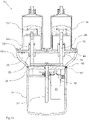
- device 11 made in accordance with a preferred embodiment of the invention includes a first supporting plate or frame 13.
- An axial guide 15 for a threaded primary rod 17 is defined in plate 13.
- plate 13 is made of plastics or more preferably of metal, e.g. aluminium.
- Primary rod 13 passes through said first plate 13 within axial guide 15.
- axial guide 15 consists of a corresponding hole passing through plate 13.
- axial guide 15 is defined substantially centrally of plate 13, which has, in plan view, an approximatively rectangular shape with rounded corners.
- plate 13 has no further opening besides the hole defining axial guide 15.
- Device 11 further includes a second supporting plate or frame 21.
- Two engagement seats 23a, 23b for the open rear base or end 25 of a corresponding syringe 27a, 27b are defined in plate 21.
- Said base 25 is defined in syringe barrel 55 on the side opposite opening 24 provided with a Luer-Lock connection and serving for drug delivery during infusion.
- Syringes 27a, 27b may be conventional disposable syringes made of plastic material and provided with radially projecting wings 31 at base 25.
- a guide 26 for the axial sliding of a corresponding secondary rod 29a, 29b is associated with each engagement seat 23a, 23b.
- Guides 26 are located substantially centrally of engagement seats 23a, 23b. Secondary rods 29a, 29b pass through the second plate 21 within corresponding guides 26.
- seats 23a, 23b are made so that they can house base 25 of a disposable syringe 27a, 27b provided with radially projecting wings 31. Consequently, each seat 23a, 23b is substantially circular and is surrounded by a pair of diametrically opposite and interrupted annular grooves 33 defining the female part of a bayonet-like coupling for the corresponding syringe 27a, 27b.
- guides 26 are made as ferrules 28 integrally made with supporting plate 21, which will be preferably made of aluminium.
- ferrules 28 have an internal surface with low frictional coefficient, made for instance of anodised aluminium, in order to make sliding of secondary rods 29a, 29b in the corresponding ferrule 28 easier.
- the second plate 21 has no further opening besides holes 35 provided in ferrules 28 for the passage of secondary rods 29a, 29b. As it will become more apparent from the following description, the second plate 21 separates the environment outside device 11, which is faced by syringe engagement seats 23a, 23b, from the environment inside device 11.
- ferrule 28 further defines a substantially tight seal with respect to the corresponding secondary rod 29 a, 29b, thereby making device 11 substantially tightly sealed.
- Device 11 further includes an electric motor 37 having a rotatable driving shaft 39.
- electric motor 37 is controlled by a programmable electronic control unit associated with a control panel 40 accessible from the outside of device 11 and is supplied by a battery.
- control unit and the battery will be housed within device 11.
- the motion converting assembly includes a pinion 41 associated with driving shaft 39 of electric motor 37 and a gear ring 43 engaged in pinion 41.
- Gear ring 43 surrounds an internally threaded screw nut 45 cooperating with the external thread of primary rod 17.
- Screw nut 45 caused by the rotation of gear ring 43 induced by the rotation of pinion 41 and driving shaft 39 of electric motor 37, causes the axial sliding of externally threaded primary rod 17 through the first supporting plate 13 within axial guide 15.
- Screw nut 45 is rotatably supported by a third supporting plate or frame 47 of device 11, to which motor 37 is fastened.
- a thrust ball bearing 48 is preferably provided between plate 47 and screw nut 45.
- device 11 is equipped with at least one pair of connecting arms 49a, 49b adapted to transmit the axial sliding motion of primary rod 17 to a corresponding one of said secondary rods 29a, 29b.
- arms 49a, 49b are separate and are firmly fastened to primary rod 17 and secondary rods 29a, 29b, which will be provided with corresponding radial holes for receiving the ends of connecting arms 49a, 49b.
- connecting arms 49a, 49b could be made as a single piece, and in yet other embodiments primary rod 17, connecting arms 49a, 49b and secondary rods 29a, 29b could be made as a single piece, thereby forming a single component.
- Connecting arms 49a, 49b are arranged substantially perpendicularly to primary rod 17 and secondary rods 29a, 29b.
- the assembly consisting of primary rod 17, connecting arms 49a, 49b and secondary rods 29a, 29b defines a substantially fork-like configuration. Therefore, according to the invention, the rotary movement of driving shaft 39 of electric motor 37 causes the axial sliding of heads 51 of secondary rods 29a, 29b and, consequently, the sliding of plungers 53 in barrels 55 of syringes 27a, 27b, when said syringes are engaged in the corresponding engagement seats 23a, 23b.
- device 11 is shown in the infusion start configuration, i.e. when syringes 27a, 27b inserted into engagement seats 23a, 23b are filled with liquid and the corresponding plungers 53 are wholly withdrawn.
- connecting arms 49a, 49b are in a wholly withdrawn position, close to the first plate 13.
- Primary rod 17 and secondary rods 29a, 29b also are wholly withdrawn.
- device 11 is shown in the infusion end configuration, i.e. when syringes 27a, 27b inserted into engagement seats 23a, 23b no longer contain liquid and the corresponding plungers 53 are wholly advanced towards opening 24 of the front end of the syringe.
- connecting arms 49a, 49b are in a wholly advanced position close to the second plate 21.
- Primary rod 17 and secondary rods 29a, 29b also are wholly advanced.
- first supporting plate 13 and the second supporting plate 21 are parallel to each other and are firmly associated along their corresponding perimeters inside a casing 57 of device 11, also housing motor 37 and the motion converting assembly.
- casing 57 includes a main portion 59 and an interface portion 61, mutually connected.
- Motor 37 and the motion converting assembly are housed in the main portion.
- the battery supplying the device with power and the electronic control unit of the device are housed in said main portion.
- the seat for the battery housed in main portion 59 of the casing is accessible from the outside through a cover 60.
- Main portion 59 has a substantially constant cross-section along an axis parallel to primary rod 17 and interface portion 61 has a bell-shaped cross-section that widens in a direction away from main portion 59 and parallel to the axis of primary rod 17.
- Bell-shaped interface portion 61 is open at its opposed ends and has a side wall 62 without openings. The wider opening of interface portion 61 is closed by the second plate 21 provided with engagement seats 23a, 23b for syringes 27a, 27b.
- a sealing gasket 63 preventing the inlet of liquids and humidity into interface portion 61 is provided between the peripheral edge of plate 21 and the rim of the opening of interface portion 61.
- the first plate 13 is located between interface portion 61 and main portion 59 of casing 57.
- a first sealing gasket 65 preventing the inlet of humidity and liquids coming from the outside into interface portion 61 is provided between the peripheral edge of the first plate 13 and the adjacent surface of the edge of main portion 59.
- a second sealing gasket 67 preventing the inlet of humidity and liquids coming from the outside into main portion 59 is provided between the peripheral edge of the first plate 13 and the adjacent surface of the edge of main portion 59.
Landscapes
- Health & Medical Sciences (AREA)
- Vascular Medicine (AREA)
- Engineering & Computer Science (AREA)
- Anesthesiology (AREA)
- Biomedical Technology (AREA)
- Heart & Thoracic Surgery (AREA)
- Hematology (AREA)
- Life Sciences & Earth Sciences (AREA)
- Animal Behavior & Ethology (AREA)
- General Health & Medical Sciences (AREA)
- Public Health (AREA)
- Veterinary Medicine (AREA)
- Infusion, Injection, And Reservoir Apparatuses (AREA)
- Surgical Instruments (AREA)
- Saccharide Compounds (AREA)
- Seal Device For Vehicle (AREA)
Claims (10)
- Spritzenbetätigungsvorrichtung (11) mit:- einer ersten Trägerplatte oder Rahmen (13), in der eine axiale Führung (15) für eine Primärstange (17) ausgebildet ist,- einer zweiten Trägerplatte oder Rahmen (21), die wenigstens zwei Aufnahmesitze (23a, 23b) für die Basen (25) von entsprechenden Spitzen (27a, 27b), die einen Spritzenzylinder (55) und einen beweglichen Kolben (53) haben, eine Führung (26) für das axiale Gleiten einer entsprechenden zweiten Stange (29a, 29b), die einen Kopf (51) aufweist, der einem der beiden Aufnahmesitze (23a, 23b) zugeordnet ist, bildet,- einem Elektromotor (37), der eine Antriebswelle (39) hat,- einer Baugruppe zum Umwandeln der Drehbewegung der Antriebswelle (39) des Elektromotors (37) in eine translatorische Bewegung des Primärstanges (17),- wenigstens einem Paar Verbindungsarme (49a, 49b), die dafür ausgelegt sind, die axiale Gleitbewegung der Primärstange (17) auf eine der Sekundärstangen (29a, 29b) zu übertragen, wodurch die Drehbewegung der Antriebswelle (39) des Elektromotors (37) das Gleiten der Sekundärstangen (29a, 29b) und folglich das Gleiten der Kolben (53) der Spritzen (27a, 27b) bewirkt, wenn die Spritzen in den entsprechenden Aufnahmesitzen (23a, 23b) sitzen und die Kolben (53) an die Köpfe (51) anstoßen,wobei die Vorrichtung dadurch gekennzeichnet ist, dass die zweite Trägerplatte (21) an jeden Aufnahmesitz (23a, 23b) für die Spritze mit einer Hülse (28) versehen ist, welche die Führung (26) für die axiale Verschiebung bildet, eine Dichtung (19), die eine Abdichtung zwischen den Hülsen (28) und der entsprechenden Sekundärstange (29a, 29b) bewirkt und verhindert, dass Feuchtigkeit und Flüssigkeit durch die Hülsen (28) hindurchtritt, zwischen einer Hülse (28) und dem entsprechenden Sekundärstange (29a, 29b) angeordnet ist, und dass die Hülsen (28) einstückig mit der zweiten Trägerplatte (21) ausgebildet sind.
- Vorrichtung nach Anspruch 1, wobei die Aufnahmesitze (23a, 23b) dafür ausgelegt sind, die hintere Basis (25) einer Einwegspritze (27a, 27b) aufzunehmen, die mit radial vorstehenden Flügeln (31) versehen ist und somit den weiblichen Teil einer bajonettartigen Koppelung für die entsprechende Spritze (27a, 27b) bildet.
- Vorrichtung nach Anspruch 1 oder 2, wobei die Dichtung (19), die zwischen den Hülsen (28) und den Sekundärstangen (29a, 29b) angeordnet ist, einen O-Ring aufweist, der aus Gummi oder anderem geeignetem Material hergestellt ist.
- Vorrichtung nach Anspruch 1 oder 2 oder 3, wobei die Bewegung umwandelnde Baugruppe ein Ritzel (41), das der Antriebswelle (39) des Elektromotors (37) zugeordnet ist, und ein Zahnrad (43), das in das Ritzel (41) eingreift und eine mit einem Innengewinde versehene Mutter (45) umgibt, die mit einem Außengewinde der Primärstange (17) zusammenwirkt, aufweist, wobei die Drehung der Gewindemutter (45), die durch Drehung des Zahnrads (43) bewirkt wird, die durch Drehung des Ritzels (41) und der Antriebswelle (39) des Elektromotors (37) induziert wird, die axiale Verschiebung der Primärstange (17), die durch die erste Trägerplatte (13) hindurch an der axialen Führung (15) verläuft, sowie über die Verbindungsarme (49a, 49b) der axialen Verschiebung der Sekundärstange (29a, 29b), die durch die zweite Trägerplatte an der axialen Führung (26) hindurch verlaufen, bewirkt.
- Vorrichtung nach Anspruch 4, wobei die Gewindemutter (45) drehbar von einer dritten Trägerplatte oder einem Rahmen (47) der Vorrichtung (11) getragen ist, wobei ein axiales Kugellager (48) zwischen der dritten Platte (47) und der Gewindemutter (45) vorgesehen ist.
- Vorrichtung nach einem der vorstehenden Ansprüche, wobei die Verbindungsarme (49a, 49b) im Wesentlichen senkrecht zu dem Primärstange (17) und den Sekundärstangen (29a, 29b) angeordnet sind und wobei die Baugruppe, die aus der Primärstange (17), den Verbindungsarmen (49a, 49b) und der Sekundärstange (49a, 29b) besteht, eine im Wesentlichen gabelartige Anordnung bildet.
- Vorrichtung nach einem der vorstehenden Ansprüche, wobei die erste und die zweite Trägerplatte (13, 21) parallel zueinander und einander entlang ihrer ansprechenden Ränder innerhalb des Gehäuses (57) der Vorrichtung (11) fest zugeordnet sind.
- Vorrichtung nach Anspruch 7, wobei das Gehäuse (57) einen Hauptabschnitt (59), in dem der Motor (37) und die Bewegung umwandelnde Baugruppe angeordnet sind, und einen Verbindungsabschnitt (61), der mit einer der Basen des Hauptabschnitts (59) verbunden ist und dem die zweite Trägerplatte (21) abgedichtet zugeordnet ist, aufweist.
- Vorrichtung nach Anspruch 8, wobei der Hauptabschnitt (59) entlang einer parallel zu dem Primärstange (17) verlaufenden Achse einen im Wesentlichen konstanten Querschnitt hat und der Verbindungsabschnitt (61) einen glockenförmigen Querschnitt hat, der sich in einer Richtung weg von dem Hauptabschnitt und parallel zu der Achse der Primärstange (17) aufweitet.
- Vorrichtung nach Anspruch 9, wobei die erste Platte (13) an ihrem Umfang abgedichtet an der Innenwand des Gehäuses (57) angebracht ist, wobei der Hauptabschnitt (59) des Gehäuses (57) im Wesentlichen abgedichtet von der Umgebung der Vorrichtung (11) isoliert ist.
Applications Claiming Priority (2)
| Application Number | Priority Date | Filing Date | Title |
|---|---|---|---|
| IT102016000093803A IT201600093803A1 (it) | 2016-09-19 | 2016-09-19 | Dispositivo di azionamento per siringhe |
| PCT/IB2017/055595 WO2018051281A1 (en) | 2016-09-19 | 2017-09-15 | Syringe actuating device |
Publications (2)
| Publication Number | Publication Date |
|---|---|
| EP3515534A1 EP3515534A1 (de) | 2019-07-31 |
| EP3515534B1 true EP3515534B1 (de) | 2023-01-25 |
Family
ID=58606479
Family Applications (1)
| Application Number | Title | Priority Date | Filing Date |
|---|---|---|---|
| EP17780893.8A Active EP3515534B1 (de) | 2016-09-19 | 2017-09-15 | Spritzenbetätigungsvorrichtung |
Country Status (4)
| Country | Link |
|---|---|
| US (1) | US11273253B2 (de) |
| EP (1) | EP3515534B1 (de) |
| IT (1) | IT201600093803A1 (de) |
| WO (1) | WO2018051281A1 (de) |
Cited By (1)
| Publication number | Priority date | Publication date | Assignee | Title |
|---|---|---|---|---|
| US20220080113A1 (en) * | 2018-12-31 | 2022-03-17 | Cane' S.P.A. | Portable pump for drug infusion through a syringe removably engaged in the pump |
Families Citing this family (3)
| Publication number | Priority date | Publication date | Assignee | Title |
|---|---|---|---|---|
| IT201800006427A1 (it) | 2018-06-18 | 2019-12-18 | Pompa compatta a ricarica rapida di sicurezza per la somministrazione di farmaci | |
| EP4740980A2 (de) * | 2018-12-31 | 2026-05-13 | Cane' S.P.A. | Schale für eine tragbare elektromechanische vorrichtung zur arzneimittelinfusion |
| US12042624B2 (en) | 2021-08-12 | 2024-07-23 | Cane' S.P.A. | Manually operated mechanical pump for drug infusion |
Family Cites Families (12)
| Publication number | Priority date | Publication date | Assignee | Title |
|---|---|---|---|---|
| IT1307266B1 (it) | 1999-08-13 | 2001-10-30 | Cane Srl | Apparecchio per infusione di farmaci. |
| US7670315B2 (en) * | 2005-01-21 | 2010-03-02 | Medrad, Inc. | Injectors, injector systems and methods for injecting fluids |
| US20080045925A1 (en) * | 2006-06-19 | 2008-02-21 | Stepovich Matthew J | Drug delivery system |
| USD659234S1 (en) | 2006-08-11 | 2012-05-08 | Cane S.R.L. | Drug infusion device with a protective cap |
| EP2289581B1 (de) * | 2006-10-11 | 2013-11-06 | Mallinckrodt LLC | Injektor mit geringer Einspritzleistung |
| KR100906825B1 (ko) * | 2008-12-09 | 2009-07-09 | (주)세일글로발 | 이액형 의료용 점성유체 압출건 |
| IT1404942B1 (it) * | 2010-06-11 | 2013-12-09 | Cane Spa | Dispositivo per l'infusione simultanea di farmaci in piu' siti di infusione. |
| IT1403780B1 (it) * | 2010-12-02 | 2013-10-31 | Cane Spa | Dispositivo per l'infusione di farmaci. |
| US20120245560A1 (en) * | 2011-03-22 | 2012-09-27 | Hochman Mark N | Multi-vessel computer control drug delivery |
| ITTO20130467A1 (it) | 2013-06-06 | 2014-12-07 | Cane Spa | Serbatoio per dispositivo infusore di farmaci. |
| ITTO20130661A1 (it) * | 2013-08-02 | 2015-02-03 | Cane Spa | Pompa portatile per l¿infusione di sostanze liquide nel corpo di un essere vivente e serbatoio per l¿uso in detta pompa |
| ITUA20164003A1 (it) | 2016-05-31 | 2017-12-01 | Cane Spa | Sistema di collegamento di una siringa ad una pompa per infusione di farmaci |
-
2016
- 2016-09-19 IT IT102016000093803A patent/IT201600093803A1/it unknown
-
2017
- 2017-09-15 EP EP17780893.8A patent/EP3515534B1/de active Active
- 2017-09-15 WO PCT/IB2017/055595 patent/WO2018051281A1/en not_active Ceased
- 2017-09-15 US US16/334,259 patent/US11273253B2/en active Active
Cited By (2)
| Publication number | Priority date | Publication date | Assignee | Title |
|---|---|---|---|---|
| US20220080113A1 (en) * | 2018-12-31 | 2022-03-17 | Cane' S.P.A. | Portable pump for drug infusion through a syringe removably engaged in the pump |
| US12508359B2 (en) * | 2018-12-31 | 2025-12-30 | Cane' S.P.A. | Portable pump for drug infusion through a syringe removably engaged in the pump |
Also Published As
| Publication number | Publication date |
|---|---|
| US11273253B2 (en) | 2022-03-15 |
| EP3515534A1 (de) | 2019-07-31 |
| IT201600093803A1 (it) | 2018-03-19 |
| US20190209772A1 (en) | 2019-07-11 |
| WO2018051281A1 (en) | 2018-03-22 |
Similar Documents
| Publication | Publication Date | Title |
|---|---|---|
| US11273253B2 (en) | Syringe actuating device | |
| US12268839B2 (en) | Drive mechanism for infusion pump | |
| CN101239205B (zh) | 注射器组件和包括其的输液泵组件 | |
| US4666430A (en) | Infusion pump | |
| EP2832389B1 (de) | Tragbare wasserdichte Infusionspumpe und Reservoir zur Verwendung in einer solchen Pumpe | |
| KR102650782B1 (ko) | 인퓨전 장치 | |
| CA3001887C (en) | Systems for fluid delivery with wicking membrane | |
| US10188789B2 (en) | Fluid infusion device with safety coupling | |
| US10279128B2 (en) | Systems for managing reservoir chamber pressure | |
| US20220339423A1 (en) | Medical connector with automatic sealing on disconnection | |
| EP1789115A1 (de) | Reservoir für eine vom vorderen ende geladene infusionsvorrichtung | |
| US6095757A (en) | Liquid drug infusion pump | |
| EP3288630B1 (de) | Fluidstecker, fluidbuchse und fluidverbindungssystem damit | |
| CN113663160A (zh) | 注射装置及医疗器械 | |
| WO2021102292A1 (en) | Hand tool with integrated micropump and drug reservoir for intracochlear drug delivery | |
| KR20030004630A (ko) | 인슐린 자동주사기용 주사침 유니트 | |
| US20050177110A1 (en) | Device for locking syringes to infusion pumps | |
| US9833563B2 (en) | Systems for managing reservoir chamber pressure | |
| EP3914220B1 (de) | Zuführkappe, antriebskopf und antriebssystem | |
| RU2824350C2 (ru) | Многофлюидная система доставки с многоразовым расходным комплектом и ее конструкционные особенности | |
| HK40064670B (en) | Feeding cap, drive head, and drive system |
Legal Events
| Date | Code | Title | Description |
|---|---|---|---|
| STAA | Information on the status of an ep patent application or granted ep patent |
Free format text: STATUS: UNKNOWN |
|
| STAA | Information on the status of an ep patent application or granted ep patent |
Free format text: STATUS: THE INTERNATIONAL PUBLICATION HAS BEEN MADE |
|
| PUAI | Public reference made under article 153(3) epc to a published international application that has entered the european phase |
Free format text: ORIGINAL CODE: 0009012 |
|
| STAA | Information on the status of an ep patent application or granted ep patent |
Free format text: STATUS: REQUEST FOR EXAMINATION WAS MADE |
|
| 17P | Request for examination filed |
Effective date: 20190318 |
|
| AK | Designated contracting states |
Kind code of ref document: A1 Designated state(s): AL AT BE BG CH CY CZ DE DK EE ES FI FR GB GR HR HU IE IS IT LI LT LU LV MC MK MT NL NO PL PT RO RS SE SI SK SM TR |
|
| AX | Request for extension of the european patent |
Extension state: BA ME |
|
| DAV | Request for validation of the european patent (deleted) | ||
| DAX | Request for extension of the european patent (deleted) | ||
| GRAP | Despatch of communication of intention to grant a patent |
Free format text: ORIGINAL CODE: EPIDOSNIGR1 |
|
| STAA | Information on the status of an ep patent application or granted ep patent |
Free format text: STATUS: GRANT OF PATENT IS INTENDED |
|
| INTG | Intention to grant announced |
Effective date: 20220819 |
|
| GRAS | Grant fee paid |
Free format text: ORIGINAL CODE: EPIDOSNIGR3 |
|
| GRAA | (expected) grant |
Free format text: ORIGINAL CODE: 0009210 |
|
| STAA | Information on the status of an ep patent application or granted ep patent |
Free format text: STATUS: THE PATENT HAS BEEN GRANTED |
|
| AK | Designated contracting states |
Kind code of ref document: B1 Designated state(s): AL AT BE BG CH CY CZ DE DK EE ES FI FR GB GR HR HU IE IS IT LI LT LU LV MC MK MT NL NO PL PT RO RS SE SI SK SM TR |
|
| REG | Reference to a national code |
Ref country code: GB Ref legal event code: FG4D |
|
| REG | Reference to a national code |
Ref country code: CH Ref legal event code: EP |
|
| REG | Reference to a national code |
Ref country code: DE Ref legal event code: R096 Ref document number: 602017065774 Country of ref document: DE |
|
| REG | Reference to a national code |
Ref country code: AT Ref legal event code: REF Ref document number: 1545511 Country of ref document: AT Kind code of ref document: T Effective date: 20230215 Ref country code: IE Ref legal event code: FG4D |
|
| REG | Reference to a national code |
Ref country code: LT Ref legal event code: MG9D |
|
| REG | Reference to a national code |
Ref country code: NL Ref legal event code: MP Effective date: 20230125 |
|
| REG | Reference to a national code |
Ref country code: AT Ref legal event code: MK05 Ref document number: 1545511 Country of ref document: AT Kind code of ref document: T Effective date: 20230125 |
|
| PG25 | Lapsed in a contracting state [announced via postgrant information from national office to epo] |
Ref country code: NL Free format text: LAPSE BECAUSE OF FAILURE TO SUBMIT A TRANSLATION OF THE DESCRIPTION OR TO PAY THE FEE WITHIN THE PRESCRIBED TIME-LIMIT Effective date: 20230125 |
|
| PG25 | Lapsed in a contracting state [announced via postgrant information from national office to epo] |
Ref country code: RS Free format text: LAPSE BECAUSE OF FAILURE TO SUBMIT A TRANSLATION OF THE DESCRIPTION OR TO PAY THE FEE WITHIN THE PRESCRIBED TIME-LIMIT Effective date: 20230125 Ref country code: PT Free format text: LAPSE BECAUSE OF FAILURE TO SUBMIT A TRANSLATION OF THE DESCRIPTION OR TO PAY THE FEE WITHIN THE PRESCRIBED TIME-LIMIT Effective date: 20230525 Ref country code: NO Free format text: LAPSE BECAUSE OF FAILURE TO SUBMIT A TRANSLATION OF THE DESCRIPTION OR TO PAY THE FEE WITHIN THE PRESCRIBED TIME-LIMIT Effective date: 20230425 Ref country code: LV Free format text: LAPSE BECAUSE OF FAILURE TO SUBMIT A TRANSLATION OF THE DESCRIPTION OR TO PAY THE FEE WITHIN THE PRESCRIBED TIME-LIMIT Effective date: 20230125 Ref country code: LT Free format text: LAPSE BECAUSE OF FAILURE TO SUBMIT A TRANSLATION OF THE DESCRIPTION OR TO PAY THE FEE WITHIN THE PRESCRIBED TIME-LIMIT Effective date: 20230125 Ref country code: HR Free format text: LAPSE BECAUSE OF FAILURE TO SUBMIT A TRANSLATION OF THE DESCRIPTION OR TO PAY THE FEE WITHIN THE PRESCRIBED TIME-LIMIT Effective date: 20230125 Ref country code: ES Free format text: LAPSE BECAUSE OF FAILURE TO SUBMIT A TRANSLATION OF THE DESCRIPTION OR TO PAY THE FEE WITHIN THE PRESCRIBED TIME-LIMIT Effective date: 20230125 Ref country code: AT Free format text: LAPSE BECAUSE OF FAILURE TO SUBMIT A TRANSLATION OF THE DESCRIPTION OR TO PAY THE FEE WITHIN THE PRESCRIBED TIME-LIMIT Effective date: 20230125 |
|
| PG25 | Lapsed in a contracting state [announced via postgrant information from national office to epo] |
Ref country code: SE Free format text: LAPSE BECAUSE OF FAILURE TO SUBMIT A TRANSLATION OF THE DESCRIPTION OR TO PAY THE FEE WITHIN THE PRESCRIBED TIME-LIMIT Effective date: 20230125 Ref country code: PL Free format text: LAPSE BECAUSE OF FAILURE TO SUBMIT A TRANSLATION OF THE DESCRIPTION OR TO PAY THE FEE WITHIN THE PRESCRIBED TIME-LIMIT Effective date: 20230125 Ref country code: IS Free format text: LAPSE BECAUSE OF FAILURE TO SUBMIT A TRANSLATION OF THE DESCRIPTION OR TO PAY THE FEE WITHIN THE PRESCRIBED TIME-LIMIT Effective date: 20230525 Ref country code: GR Free format text: LAPSE BECAUSE OF FAILURE TO SUBMIT A TRANSLATION OF THE DESCRIPTION OR TO PAY THE FEE WITHIN THE PRESCRIBED TIME-LIMIT Effective date: 20230426 Ref country code: FI Free format text: LAPSE BECAUSE OF FAILURE TO SUBMIT A TRANSLATION OF THE DESCRIPTION OR TO PAY THE FEE WITHIN THE PRESCRIBED TIME-LIMIT Effective date: 20230125 |
|
| REG | Reference to a national code |
Ref country code: DE Ref legal event code: R097 Ref document number: 602017065774 Country of ref document: DE |
|
| PG25 | Lapsed in a contracting state [announced via postgrant information from national office to epo] |
Ref country code: SM Free format text: LAPSE BECAUSE OF FAILURE TO SUBMIT A TRANSLATION OF THE DESCRIPTION OR TO PAY THE FEE WITHIN THE PRESCRIBED TIME-LIMIT Effective date: 20230125 Ref country code: RO Free format text: LAPSE BECAUSE OF FAILURE TO SUBMIT A TRANSLATION OF THE DESCRIPTION OR TO PAY THE FEE WITHIN THE PRESCRIBED TIME-LIMIT Effective date: 20230125 Ref country code: EE Free format text: LAPSE BECAUSE OF FAILURE TO SUBMIT A TRANSLATION OF THE DESCRIPTION OR TO PAY THE FEE WITHIN THE PRESCRIBED TIME-LIMIT Effective date: 20230125 Ref country code: DK Free format text: LAPSE BECAUSE OF FAILURE TO SUBMIT A TRANSLATION OF THE DESCRIPTION OR TO PAY THE FEE WITHIN THE PRESCRIBED TIME-LIMIT Effective date: 20230125 Ref country code: CZ Free format text: LAPSE BECAUSE OF FAILURE TO SUBMIT A TRANSLATION OF THE DESCRIPTION OR TO PAY THE FEE WITHIN THE PRESCRIBED TIME-LIMIT Effective date: 20230125 |
|
| PG25 | Lapsed in a contracting state [announced via postgrant information from national office to epo] |
Ref country code: SK Free format text: LAPSE BECAUSE OF FAILURE TO SUBMIT A TRANSLATION OF THE DESCRIPTION OR TO PAY THE FEE WITHIN THE PRESCRIBED TIME-LIMIT Effective date: 20230125 |
|
| PLBE | No opposition filed within time limit |
Free format text: ORIGINAL CODE: 0009261 |
|
| STAA | Information on the status of an ep patent application or granted ep patent |
Free format text: STATUS: NO OPPOSITION FILED WITHIN TIME LIMIT |
|
| 26N | No opposition filed |
Effective date: 20231026 |
|
| PG25 | Lapsed in a contracting state [announced via postgrant information from national office to epo] |
Ref country code: SI Free format text: LAPSE BECAUSE OF FAILURE TO SUBMIT A TRANSLATION OF THE DESCRIPTION OR TO PAY THE FEE WITHIN THE PRESCRIBED TIME-LIMIT Effective date: 20230125 |
|
| REG | Reference to a national code |
Ref country code: CH Ref legal event code: PL |
|
| PG25 | Lapsed in a contracting state [announced via postgrant information from national office to epo] |
Ref country code: LU Free format text: LAPSE BECAUSE OF NON-PAYMENT OF DUE FEES Effective date: 20230915 |
|
| REG | Reference to a national code |
Ref country code: BE Ref legal event code: MM Effective date: 20230930 |
|
| PG25 | Lapsed in a contracting state [announced via postgrant information from national office to epo] |
Ref country code: LU Free format text: LAPSE BECAUSE OF NON-PAYMENT OF DUE FEES Effective date: 20230915 Ref country code: MC Free format text: LAPSE BECAUSE OF FAILURE TO SUBMIT A TRANSLATION OF THE DESCRIPTION OR TO PAY THE FEE WITHIN THE PRESCRIBED TIME-LIMIT Effective date: 20230125 |
|
| REG | Reference to a national code |
Ref country code: IE Ref legal event code: MM4A |
|
| PG25 | Lapsed in a contracting state [announced via postgrant information from national office to epo] |
Ref country code: IE Free format text: LAPSE BECAUSE OF NON-PAYMENT OF DUE FEES Effective date: 20230915 |
|
| PG25 | Lapsed in a contracting state [announced via postgrant information from national office to epo] |
Ref country code: CH Free format text: LAPSE BECAUSE OF NON-PAYMENT OF DUE FEES Effective date: 20230930 |
|
| PG25 | Lapsed in a contracting state [announced via postgrant information from national office to epo] |
Ref country code: IE Free format text: LAPSE BECAUSE OF NON-PAYMENT OF DUE FEES Effective date: 20230915 Ref country code: CH Free format text: LAPSE BECAUSE OF NON-PAYMENT OF DUE FEES Effective date: 20230930 |
|
| PG25 | Lapsed in a contracting state [announced via postgrant information from national office to epo] |
Ref country code: BE Free format text: LAPSE BECAUSE OF NON-PAYMENT OF DUE FEES Effective date: 20230930 |
|
| PG25 | Lapsed in a contracting state [announced via postgrant information from national office to epo] |
Ref country code: BG Free format text: LAPSE BECAUSE OF FAILURE TO SUBMIT A TRANSLATION OF THE DESCRIPTION OR TO PAY THE FEE WITHIN THE PRESCRIBED TIME-LIMIT Effective date: 20230125 |
|
| PG25 | Lapsed in a contracting state [announced via postgrant information from national office to epo] |
Ref country code: BG Free format text: LAPSE BECAUSE OF FAILURE TO SUBMIT A TRANSLATION OF THE DESCRIPTION OR TO PAY THE FEE WITHIN THE PRESCRIBED TIME-LIMIT Effective date: 20230125 |
|
| PG25 | Lapsed in a contracting state [announced via postgrant information from national office to epo] |
Ref country code: CY Free format text: LAPSE BECAUSE OF FAILURE TO SUBMIT A TRANSLATION OF THE DESCRIPTION OR TO PAY THE FEE WITHIN THE PRESCRIBED TIME-LIMIT; INVALID AB INITIO Effective date: 20170915 |
|
| PG25 | Lapsed in a contracting state [announced via postgrant information from national office to epo] |
Ref country code: HU Free format text: LAPSE BECAUSE OF FAILURE TO SUBMIT A TRANSLATION OF THE DESCRIPTION OR TO PAY THE FEE WITHIN THE PRESCRIBED TIME-LIMIT; INVALID AB INITIO Effective date: 20170915 |
|
| PGFP | Annual fee paid to national office [announced via postgrant information from national office to epo] |
Ref country code: DE Payment date: 20250922 Year of fee payment: 9 |
|
| PGFP | Annual fee paid to national office [announced via postgrant information from national office to epo] |
Ref country code: IT Payment date: 20250919 Year of fee payment: 9 |
|
| PGFP | Annual fee paid to national office [announced via postgrant information from national office to epo] |
Ref country code: GB Payment date: 20250926 Year of fee payment: 9 |
|
| PGFP | Annual fee paid to national office [announced via postgrant information from national office to epo] |
Ref country code: FR Payment date: 20250821 Year of fee payment: 9 |
|
| PG25 | Lapsed in a contracting state [announced via postgrant information from national office to epo] |
Ref country code: TR Free format text: LAPSE BECAUSE OF FAILURE TO SUBMIT A TRANSLATION OF THE DESCRIPTION OR TO PAY THE FEE WITHIN THE PRESCRIBED TIME-LIMIT Effective date: 20230125 |