EP3515529B1 - Einsatzstück für einen blutschlauchsatz zum begünstigen einer vermischung einer infusionslösung mit einem weiteren fluid - Google Patents
Einsatzstück für einen blutschlauchsatz zum begünstigen einer vermischung einer infusionslösung mit einem weiteren fluid Download PDFInfo
- Publication number
- EP3515529B1 EP3515529B1 EP17777230.8A EP17777230A EP3515529B1 EP 3515529 B1 EP3515529 B1 EP 3515529B1 EP 17777230 A EP17777230 A EP 17777230A EP 3515529 B1 EP3515529 B1 EP 3515529B1
- Authority
- EP
- European Patent Office
- Prior art keywords
- line
- blood
- insert piece
- main line
- lumen
- Prior art date
- Legal status (The legal status is an assumption and is not a legal conclusion. Google has not performed a legal analysis and makes no representation as to the accuracy of the status listed.)
- Active
Links
Images


Classifications
-
- A—HUMAN NECESSITIES
- A61—MEDICAL OR VETERINARY SCIENCE; HYGIENE
- A61M—DEVICES FOR INTRODUCING MEDIA INTO, OR ONTO, THE BODY; DEVICES FOR TRANSDUCING BODY MEDIA OR FOR TAKING MEDIA FROM THE BODY; DEVICES FOR PRODUCING OR ENDING SLEEP OR STUPOR
- A61M1/00—Suction or pumping devices for medical purposes; Devices for carrying-off, for treatment of, or for carrying-over, body-liquids; Drainage systems
- A61M1/34—Filtering material out of the blood by passing it through a membrane, i.e. hemofiltration or diafiltration
- A61M1/342—Adding solutions to the blood, e.g. substitution solutions
- A61M1/3455—Substitution fluids
- A61M1/3465—Substitution fluids using dialysate as substitution fluid
-
- A—HUMAN NECESSITIES
- A61—MEDICAL OR VETERINARY SCIENCE; HYGIENE
- A61M—DEVICES FOR INTRODUCING MEDIA INTO, OR ONTO, THE BODY; DEVICES FOR TRANSDUCING BODY MEDIA OR FOR TAKING MEDIA FROM THE BODY; DEVICES FOR PRODUCING OR ENDING SLEEP OR STUPOR
- A61M1/00—Suction or pumping devices for medical purposes; Devices for carrying-off, for treatment of, or for carrying-over, body-liquids; Drainage systems
- A61M1/34—Filtering material out of the blood by passing it through a membrane, i.e. hemofiltration or diafiltration
- A61M1/3472—Filtering material out of the blood by passing it through a membrane, i.e. hemofiltration or diafiltration with treatment of the filtrate
-
- A—HUMAN NECESSITIES
- A61—MEDICAL OR VETERINARY SCIENCE; HYGIENE
- A61M—DEVICES FOR INTRODUCING MEDIA INTO, OR ONTO, THE BODY; DEVICES FOR TRANSDUCING BODY MEDIA OR FOR TAKING MEDIA FROM THE BODY; DEVICES FOR PRODUCING OR ENDING SLEEP OR STUPOR
- A61M1/00—Suction or pumping devices for medical purposes; Devices for carrying-off, for treatment of, or for carrying-over, body-liquids; Drainage systems
- A61M1/36—Other treatment of blood in a by-pass of the natural circulatory system, e.g. temperature adaptation, irradiation ; Extra-corporeal blood circuits
- A61M1/3672—Means preventing coagulation
-
- A—HUMAN NECESSITIES
- A61—MEDICAL OR VETERINARY SCIENCE; HYGIENE
- A61M—DEVICES FOR INTRODUCING MEDIA INTO, OR ONTO, THE BODY; DEVICES FOR TRANSDUCING BODY MEDIA OR FOR TAKING MEDIA FROM THE BODY; DEVICES FOR PRODUCING OR ENDING SLEEP OR STUPOR
- A61M39/00—Tubes, tube connectors, tube couplings, valves, access sites or the like, specially adapted for medical use
- A61M2039/0009—Assemblies therefor designed for particular applications, e.g. contrast or saline injection, suction or irrigation
- A61M2039/0027—Assemblies therefor designed for particular applications, e.g. contrast or saline injection, suction or irrigation for mixing several substances from different containers
-
- A—HUMAN NECESSITIES
- A61—MEDICAL OR VETERINARY SCIENCE; HYGIENE
- A61M—DEVICES FOR INTRODUCING MEDIA INTO, OR ONTO, THE BODY; DEVICES FOR TRANSDUCING BODY MEDIA OR FOR TAKING MEDIA FROM THE BODY; DEVICES FOR PRODUCING OR ENDING SLEEP OR STUPOR
- A61M2206/00—Characteristics of a physical parameter; associated device therefor
- A61M2206/10—Flow characteristics
- A61M2206/14—Static flow deviators in tubes disturbing laminar flow in tubes, e.g. archimedes screws
-
- A—HUMAN NECESSITIES
- A61—MEDICAL OR VETERINARY SCIENCE; HYGIENE
- A61M—DEVICES FOR INTRODUCING MEDIA INTO, OR ONTO, THE BODY; DEVICES FOR TRANSDUCING BODY MEDIA OR FOR TAKING MEDIA FROM THE BODY; DEVICES FOR PRODUCING OR ENDING SLEEP OR STUPOR
- A61M2206/00—Characteristics of a physical parameter; associated device therefor
- A61M2206/10—Flow characteristics
- A61M2206/20—Flow characteristics having means for promoting or enhancing the flow, actively or passively
Definitions
- the invention relates to an insert piece according to the preamble of claim 1, an extracorporeal blood tubing set according to the preamble of claim 10 and a blood treatment device according to the preamble of claim 15.
- infusion solutions or medications are usually infused via the extracorporeal blood circuit, i.e. the blood tubing system used.
- the extracorporeal blood circuit i.e. the blood tubing system used.
- rapid mixing of the infusion solution with the blood may be desirable.
- in extracorporeal blood treatment routinely involves infusion of infusion solutions to inhibit blood coagulation in order to prevent possible blockage of the extracorporeal blood circuit.
- systemic and regional anticoagulation Two main methods are used for this: systemic and regional anticoagulation.
- regional anticoagulation a citrate solution is usually used as an anticoagulant, which forms a complex with calcium and thus suppresses blood clotting.
- calcium must be substituted, as too low calcium concentrations affect nerves and muscles, blood clotting and the function of the lungs, heart and kidneys.
- regional anticoagulation a calcium-containing solution is added to the blood before it is reinfused into the patient, which can permanently maintain the physiological calcium concentration in the systemic blood.
- T-pieces T-shaped addition points
- laminar flow conditions prevail at the addition point due to the circular cross-section and the smooth inner wall.
- the flow rates of the infused solutions are low compared to the blood flow.
- solutions which generate a pulsed infusion flow of the infusion solution into the blood through intermittent operation of an infusion pump.
- One task may be to propose a further solution to promote mixing of an infusion solution with another fluid, such as blood.
- the object can be achieved by an insert piece with the features of claim 1, an extracorporeal blood tubing set with the features of claim 10 and a blood treatment device with the features of claim 15.
- the insert according to the invention serves to be inserted into a blood tubing set (or into a blood tubing system) or to be part of it.
- the insert comprises at least one first connection point for connecting a first tube section of the blood tubing set to the insert. It comprises a second Connection point for connecting a second tube section of the blood tube set to the insert piece. It comprises a third connection point for connecting a third tube section of the blood tube set to the insert piece.
- It comprises a main line for conducting a first liquid, preferably blood, through the insert piece.
- the main line is in fluid communication with at least the first connection point and with the second connection point or with a lumen surrounded by the first connection point and/or with the second connection point or formed by the latter.
- the insert comprises at least one secondary line for conducting a second liquid, preferably an infusion solution, directly or indirectly, into the main line.
- the secondary line is in fluid communication with the third connection point or a lumen surrounded by it.
- the secondary line is in fluid communication with the main line in an intermediate section of the insert, which is arranged between the first connection point and the second connection point.
- the first connection point has a flow-through lumen with a first cross-sectional area.
- the second connection point has a flow-through lumen with a second cross-sectional area.
- the intermediate section has a flow-through lumen with a third cross-sectional area.
- the secondary line has a lumen section.
- the lumen section has at least one mouth or outlet opening for the second fluid. The lumen section projects into the interior of the intermediate section.
- the blood tubing set, extracorporeal blood circuit or blood tubing system according to the invention has at least one insert piece according to the invention.
- the insert according to the invention is inserted between tube sections of the blood tubing set or is manufactured integrally therewith.
- the insert according to the invention is permanently connected to tube sections of the blood tubing set, in others it is detachably connected.
- the blood treatment device according to the invention is connected to at least one blood tubing set according to the invention.
- Embodiments according to the invention can have one or more of the features mentioned above or below in any combination, each based on one of the independent claims. Embodiments according to the invention are also the subject of the dependent claims.
- the outlet opening opens into a (in the radial direction) central region of the flow-through lumen or into a central region of the intermediate section.
- the first connection point, the second connection point and/or the intermediate section each have a largely cylindrical inner wall or a section with a cylindrical inner wall.
- the insert is manufactured integrally with the blood tubing set. All or some of the sections of the insert referred to herein as connection points are, in such embodiments, transition sections between the insert and adjacent or continuing tubing sections.
- the bypass line is connected in fluid communication with a source of the infusion solution or indicates this.
- the infusion solution is a calcium solution or comprises a calcium solution.
- the invention is not limited to the use of a calcium-containing solution.
- Other drug solutions are also encompassed by the present invention. These include, in particular, a citrate solution.
- the third cross-sectional area is as large or substantially as large as the first cross-sectional area and/or the second cross-sectional area. "Substantially as large” may be considered to be 80%, 90% or more. All intermediate values, and in particular any whole number percentage (81%, 82%, 83%, etc.), are also included.
- the lumen section is designed such that the second liquid is or can be discharged from the outlet opening into or substantially in an axial direction of the main line or parallel to a main flow direction of the main line.
- This design can primarily relate to the main flow direction present in the intermediate section. This can be achieved, for example, by a kink in the secondary line in the intermediate section.
- the outlet opening is arranged to discharge the second liquid into the main line in or substantially in an axial direction of the main line or parallel to a main flow direction of the main line. This can preferably mean the main flow direction present in the intermediate section during the intended use of the insert piece.
- a section of the lumen section is provided which adjoins the outlet opening for the second liquid upstream - with respect to the second liquid when it flows towards the main line. It is arranged such that its longitudinal extension or its longitudinal axis extends parallel, or substantially parallel, to the longitudinal axis of the intermediate section or parallel to a center line of the main line.
- An impact or deflection element is provided inside the intermediate section. This element is arranged in such a way that a second liquid emerging from the outlet opening or mouth of the secondary line is limited in its radial movement or in its movement in the direction of exit.
- the impact or deflection element is not the inner wall of the main line, for example in the region of the first connection point, the second connection point or the intermediate section.
- the radially inner end of the impact or deflection element is located further radially inward than the inner wall of the main line, for example in the region of the first connection point, the second connection point or the intermediate section.
- the baffle or deflection element is part of the lumen section.
- the lumen section extends in one piece or in multiple pieces through the entire interior of the main line, in the transverse direction or in the radial direction.
- a projection extends into the interior of the intermediate section in the region of the intermediate section.
- the projection lies in an extension or in an imaginary continuation of the secondary line in the interior of the intermediate section.
- a supply line is connected in fluid communication with a blood return line and/or with a blood withdrawal line of the blood tubing set by means of the bypass line of the insert.
- the blood tubing set is designed to perform hemodialysis, hemofiltration or Suitable and/or prepared for hemodiafiltration or plasmapheresis treatment or whole blood adsorption treatment.
- the lumen portion is not a portion that abuts the inner wall of the intermediate portion or that would continue the inner wall, in particular would abut or fixate thereto without forming a radial shoulder or step.
- the lumen section projects beyond the inner wall and into the interior of the intermediate section.
- the lumen portion does not have a ring shape in a cross-sectional view of the intermediate portion.
- the lumen portion is not an aperture-shaped structure.
- the lumen section does not lie - e.g. in a cross section of the intermediate section - against the inner wall of the intermediate section in a circular manner, i.e. over the entire inner circumference of the intermediate section.
- the lumen section does not narrow the flow-through lumen of the intermediate section in a circular manner, i.e. over the entire inner circumference of the intermediate section.
- the lumen section projects into the lumen of the main line in a pin-shaped or cylindrical manner.
- the lumen portion has at least one groove which extends at least partially in a direction parallel to the main line.
- the groove can advantageously be exclusively straight. It can have a curved section in the longitudinal direction for better distribution of the fluid supplied through the secondary line.
- the groove can have a curved, triangular or any other shape in a cross-section.
- the insert is made of plastic, preferably injection-molded.
- the insert piece does not have a three-dimensional spiral structure for generating turbulence, in particular no recessed cutout in the inner wall of the intermediate section.
- the lumen portion is not configured as a raised bulge on the inner wall of the intermediate portion, or it is not a thickening of the inner wall.
- the first, second and/or third connection point is each glued to a hose section.
- the connection can be a plug-in or clamp connection or another connection.
- the blood tubing set has a drip chamber, further inserts in the form of T-pieces or injection points, etc.
- the blood tubing set is intended and/or suitable for carrying out an extracorporeal blood treatment with regional anticoagulation.
- One advantage is that, due to the injecting or introducing of the infusion solution into the blood according to the invention, no further devices or process steps are required to ensure that the infusion solution is swirled within the blood. Nevertheless, an accelerated and reliable mixing of the infusion solution with the blood can be achieved.
- An advantage of using the insert according to the invention or the blood tubing set according to the invention can also be that the advantages described here can be achieved without having to make any changes to the control of the blood treatment device or the pump for the infusion solution.
- the structure of the insert according to the invention brings about an advantageous distribution of the second fluid in the first fluid without this requiring, for example, a pulsating addition, as is the case, for example, in the EN 10 2013 011 010 A1
- the effect according to the invention can be achieved solely by means of the geometry of the insert described herein. In particular, no change in the control of the infusion pump is required. Its delivery behavior can be retained.
- the effect of the insert according to the invention is independent of the parameters of the blood treatment. If, for example, the delivery rate of the blood pump and, in line with this, the delivery rate of the pump for the infusion solution are changed, this does not change the operating principle or the effect of the insert according to the invention.
- the insert according to the invention impresses with its extremely simple and, if desired, even symmetrical design. It can be manufactured using the simplest injection molding tools, which can significantly reduce the overall cost of its production. Spiral courses and contours are just as dispensable as undercuts.
- the intermediate section has a cross-sectional area which, as the intermediate section progresses from one end to the other, increases monotonically in a first region and decreases monotonically in a second region; preferably, the cross-sectional area initially increases and then decreases again.
- the first and second regions merge directly into one another, so that the cross-sectional area preferably initially increases monotonically over the course of the intermediate section and then immediately decreases monotonically.
- the first region and the second region of the intermediate section are separated from one another, for example by the secondary line and/or the impact or deflection surface, preferably exclusively by the secondary line and/or the impact or deflection surface.
- the cross-sectional area over the course of the intermediate section preferably does not fall below 80%, particularly preferably not below 90% of the cross-sectional area of the first and/or second connection point and/or preferably does not rise above 120%, particularly preferably not above 110% of the same.
- the cross-section of the first and/or second connection point does not decrease in their respective course, in particular does not decrease continuously.
- the first connection point and the second connection point are arranged such that they lie on an axis.
- the bypass line is arranged at a right angle to this axis.
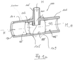
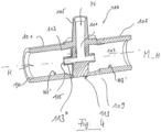
- Fig.1 shows the insert 100 according to the invention for a Fig.1 Blood tubing set 200 not shown (but see Fig.6 ) in a first exemplary embodiment in a longitudinal section.
- the insert piece 100 has a first connection point 101, by means of which a first hose section 205a (see Fig.6 ) of the blood tubing set 200 can be connected to the insert piece 100.
- the insert piece 100 has a second connection point 103, by means of which a second tube section 205b of the blood tube set 200 can be connected to the insert piece 100.
- the insert piece 100 has a third connection point 105, by means of which a third tube section, here a line for calcium solution 209 of the blood tubing set 200, can be connected to the insert piece 100.
- a third tube section here a line for calcium solution 209 of the blood tubing set 200
- the insert piece 100 has a main line 107 for conducting a first liquid, preferably blood, through the insert piece 100.
- the main line 107 is in fluid communication with the first connection point 101 and with the second connection point 103.
- the first liquid can flow into the main line 107 in the direction of the arrow H.
- the insert 100 has a longitudinal direction which is parallel to the center line of the main line 107, which is designated by the reference symbol M_H.
- the insert 100 has a transverse direction or radial direction, which is designated by r
- the insert 100 has an intermediate section 109.
- the main line 107 passes through it.
- the intermediate section 109 is in the Fig.1 by means of a dashed line.
- the insert piece 100 has a secondary line 111. It serves to guide a second liquid, preferably an infusion solution, into the main line 107.
- the second liquid can flow into the secondary line 111 in the direction of the arrow N.
- the secondary line 111 is in fluid communication with the third connection point 105. It is also in fluid communication with the main line 107 in the intermediate section 109 of the insert piece 100.
- the first connection point 101 has a flow-through lumen with a first cross-sectional area and an inner wall 101'.
- the inner wall 101' encloses an interior of the first connection point 101.
- the interior corresponds to its flow-through lumen.
- the second connection point 103 has a flow-through lumen with a second cross-sectional area and an inner wall 103'.
- the inner wall 103' encloses an interior of the second connection point 103.
- the interior corresponds to its flow-through lumen.
- the intermediate section 109 has a flow-through lumen with a third cross-sectional area and an inner wall 109'.
- the inner wall 109' encloses an interior of the intermediate section 109.
- the interior does not correspond to its flow-through lumen. Rather, the cross-sectional area of the interior is increased by the cross-sectional area of a lumen section 113, as far as this extends into the interior, larger than the permeable cross-sectional area of the lumen. If you imagine Fig.1 the lumen section 113 away, then in Fig.1 the interior corresponds to the permeable lumen.
- the center line of the main line 107 (approximately defined by the centers of the first and second cross-sectional areas, see above) is designated M_H.
- the center line M_H corresponds to the longitudinal axis of the main line 107 and its axial direction.
- the secondary line 111 has the lumen section 113, which projects into the interior of the intermediate section 109 and which has at least one mouth or outlet opening 115.
- the second liquid can be introduced into the lumen of the main line 107 through the outlet opening 115.
- the inner wall 101' encloses a flow-through lumen of the main line 107 in the region of the first connection point 101, while the inner wall 103' encloses a flow-through lumen of the main line 107 in the region of the second connection point 103.
- the inner wall 109 ⁇ encloses a flow-through lumen of the main line 107 in the region of the intermediate section 109.
- the lumen section 113 projects into the interior of the intermediate section 109.
- the lumen section 113 is not to be understood as a thickening or narrowing of the wall of the insert, but rather as an opening or continuation of the wall with the intention of moving the outlet opening 115 as far as possible radially into the flow-through interior of the main line 107 - and thus into the flow of the first liquid through the main line 107.
- the diameter of the exit opening 115 constitutes a large part of the diameter or cross-sectional area of the lumen portion 113, as described with reference to Fig.2 is further explained.
- the first connection point 101, the second connection point 103 and/or the third connection point 105 can optionally each have a bevel or chamfer 119 of the inner wall or the outer wall.
- the lumen section 113 is preferably not a section that corresponds to the inner wall 109' of the intermediate section 109 continuously. While the inner wall 109' delimits the interior of the intermediate section 109, the lumen section 113 projects beyond the inner wall 109' into the interior of the intermediate section 109.
- the lumen portion 113 is also not a structure that is annular in a cross-section of the intermediate portion 109.
- the lumen section 113 is not a diaphragm-shaped structure which forms a passage for the fluid in a cross-section of the intermediate section 109, but which would abut the inner wall 109 ⁇ in a circular manner on its outer circumference, i.e., for example, over the entire inner circumference of the intermediate section 109.
- the lumen section 113 is arranged inside the main line 107 such that liquid flowing through the lumen of the main line 107 can flow in the region of the lumen section 113 in front of it (i.e. in front of the drawing plane) as well as behind it (i.e. behind the drawing plane).
- the lumen section 113 protrudes into the interior of the main line 107 in a pin-shaped or cylindrical manner (e.g. with the center line M_N as the axis of rotation).
- An optional feature of the insert piece 100 according to the invention is that the flow-through area of the main line 107 in the area of the intermediate section 109 is not smaller than the flow-through area of the main line in the area of the first connection point 101 and/or in the area of the second connection point 103.
- Various embodiments are envisaged here according to the invention. One option is shown in Fig.1 shown; the inner wall of the intermediate section 109 is thinner compared to neighboring sections, which results in an increase in the flow-through lumen with a stepless outer wall.
- an offset of the wall of the main line 107 can be provided in the area of the intermediate section 109, such that the inner wall is offset radially outwards compared to neighboring areas, and that the outer wall is also offset radially outwards compared to neighboring areas.
- the latter is in Fig.1 not shown, the former, however, was.
- Fig. 1a shows the insert 100 according to the invention of the Fig.1 with a modification in the left branch of the main line 107.
- the inner wall 101 ⁇ of the main line 107 has a stop against which a Fig. 1a not shown hose, which is inserted into the first connection point 101, can be pushed.
- the ring-shaped stop 101a shown here as an example can be in contact with the front face of the hose, which is also ring-shaped and not shown, during use.
- the height of the stop 101a can advantageously be selected so that the inner wall of the hose is flush with the inner wall 101' of the section of the inner wall 109 ⁇ that adjoins the stop 101a to the right. In this way, the laminarity of the fluid in the stagnation area (near the wall) is not undesirably impaired.
- a stop 101a which can have the form of a step in the inner wall 101', is only shown on the left side of the insert piece 100. However, such a stop can also be provided in the area of the second connection point 103.
- Such a stop can also be provided in any other embodiment according to the invention.
- Such a stop can also be provided in any embodiment according to the invention together with a bevel or chamfer 119.
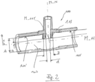
- Fig.2 shows the insert 100 according to the invention of the Fig.1 .
- Fig.2 on the reproduction of a variety of Fig.1 already known reference symbols have been omitted.
- the lumen section 113 projects into the interior of the intermediate section 109.
- the mouth or outlet opening 115 is clearly above the level of the inner wall 101' or 103' into the interior.
- the inner diameter of the main line 107 is A in the area of the first connection point 101 or in the area of the second connection point 103.
- the center point M_115 (or the geometric center of gravity) of an opening plane of the outlet opening 115 is located at a distance a from the center line M_H.
- the ratio a/A is preferably at most 0.33.
- the external diameter of the secondary line 111 in the area of the outlet opening 115 is the value D.
- the internal diameter of the secondary line 111 in the area of the outlet opening 115 is the value d.
- the ratio d/D is preferably at least 0.125.
- the ratio a/A is preferably at most 0.17, measured within a region whose points are at most 2*d away from a center line M_N of the secondary line 111.
- the second liquid can be introduced into the lumen of the main line 107 through the outlet opening 115.
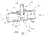
- Fig.3 shows the insert piece 100 according to the invention for a Fig.3 not shown blood tubing set 200 in a second exemplary embodiment in a longitudinal section.
- the lumen section 113 comprises portions which reach up to or extend to both opposite inner wall sections of the main line 107.
- an impact surface or deflection surface 113' is located opposite the outlet opening 115.
- the deflection surface 113' is part of the lumen section 113 or can be part of it.
- the deflection surface 113' can serve to ensure that the second liquid exiting from the outlet surface 115 is not discharged into radially outer flow areas ("stagnation areas") of the main line 107 when it exits the outlet surface 115, but rather enters the flow of the first liquid closer to the center line M_H, i.e. in an area of particularly high flow velocity.
- the design of the Fig.3 represents a more symmetrical design of the insert 100 in the area of the intermediate section 109 than that of the Fig.1 .
- With the design of the Fig.3 can help to keep the flow through the main line 107 as untouched as possible. In this way, the flow profile of the flow through the main line 107 can be left as unchanged as possible. This makes it easier to direct the second liquid in an area of highest flow velocity - relative to the first liquid in the main line 107 - into to introduce them, namely in a radially central area thereof.
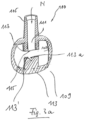
- Fig. 3a shows the insert 100 according to the invention of the Fig.3 in a cross-section.
- the flow through the main line 107 takes place in Fig. 3a mainly into or out of the drawing plane, i.e. perpendicular to the drawing plane.
- the impact surface or deflection surface 113' opposite the outlet opening 115 has a Fig.3 not visible groove 113a.
- the groove 113a is part of the lumen section 113 or can be part thereof. It preferably extends in the direction of flow through the main line 107 and is thus at least partially perpendicular to the plane of the drawing.
- the groove 113a can serve to ensure that the second liquid exiting the exit surface 115 is not discharged into radially outer flow regions ("stagnation regions") of the main line 107 when it exits the exit surface 115, but rather enters the flow of the first liquid closer to the center line M_H, i.e. in a region of particularly high flow velocity, and is guided in this over a predetermined distance due to the course of the groove 113a.
- the cross section of the groove 113a can be as in Fig. 3a shown by way of example, be triangular. Other cross-sectional shapes are also encompassed by the present invention.
- Fig.4 shows the insert piece 100 according to the invention for a Fig.4 not shown blood tubing set 200 in a third exemplary embodiment in a longitudinal section.
- the lumen section 113 comprises, in addition to those parts that Fig.3 known, and a pipe section 113" aligned in the longitudinal direction of the main line 107.
- the pipe section 113" can have a round cross-sectional shape. Other, arbitrary cross-sectional shapes are also possible and are also encompassed by the present invention.
- the longitudinal axis of the pipe section 113" coincides with the longitudinal direction or here the center line M_H of the main line 107. In other embodiments, the longitudinal axis of the pipe section 113" or its longitudinal direction is parallel to the longitudinal direction or here the center line M_H of the main line 107.
- the deflection element 113" can advantageously serve to stabilize the flow. It can advantageously help to ensure that the second liquid is actually introduced in the middle of the flow profile across the cross section, or where the flow velocity within the main line 107 is at least sufficiently high or even highest.
- the pipe section 113" can help to ensure that the second liquid exits from the outlet opening 115 in an area in which the flow in the main line 107 does not stagnate.
- Fig.5 shows the insert piece 100 according to the invention for a Fig.3 not shown blood tubing set 200 in a fourth exemplary embodiment in a longitudinal section.
- the lumen section 113 comprises the tube section 113" of the Fig.4 . Unlike in Fig.4 however, the lumen section 113 does not extend through the entire interior of the intermediate section 109. The lumen section 113 therefore reduces the flow-through lumen of the intermediate section 109 less than in Fig.4 .
- Fig.6 shows an optional, basic arrangement of an insert piece 100 according to the invention in a schematically very simplified illustrated extracorporeal blood tubing set 200 according to the invention in an exemplary embodiment.
- the blood tubing set 200 includes or is connected to a hemofilter 201.
- a blood withdrawal line 203 (or arterial line) and a blood return line 205 (or venous line) are connected to the hemofilter 201, or dialyzer or blood filter.
- the blood collection line 203 is operatively connected to or has a blood pump 301.
- a line 207 for citrate solution flows into the blood withdrawal line 203.
- the line 207 is operatively connected to or has a citrate pump 307.
- the inventive line 209 for calcium solution opens into the blood return line 205.
- the insert 100 according to the invention is operatively connected to a calcium pump 309 or has this. It is made of a Fig.1 not shown source for an infusion solution, here as an example a calcium source.
- the source can be a bag or a bottle.
- the infusion solution can be produced online; in this case, the corresponding device in which the infusion solution is produced counts as the source.
- the operative connection with the calcium pump 309 is to be understood here as exemplary.
- the present invention also encompasses an arrangement of the insert piece 100 according to the invention behind a pump other than a calcium pump, for example downstream of a citrate pump such as the citrate pump 307 of the Fig.6 .
- the hemofilter 201 is connected to a line 311 for fresh dialysis fluid and a line 315 for used dialysate or filtrate.
- the line 311 is connected to or has a dialysis fluid pump 313.
- the line 315 is connected to or has a filtrate pump 317.
- the arrowheads shown indicate the direction of flow when the blood tubing set 200 is used as intended.
- the blood tubing set 200 shown may correspond to a conventional extracorporeal blood tubing set and may be particularly suitable for CWHD ( continuous veno-venous hemodialysis ).
- CWHD continuous veno-venous hemodialysis
- the pumps 301, 307, 309, 313 and 317 can be part of a blood treatment device 300, which is only indicated schematically. The same applies to the lines 311 and 315.
Landscapes
- Health & Medical Sciences (AREA)
- Heart & Thoracic Surgery (AREA)
- Vascular Medicine (AREA)
- Engineering & Computer Science (AREA)
- Anesthesiology (AREA)
- Biomedical Technology (AREA)
- Hematology (AREA)
- Life Sciences & Earth Sciences (AREA)
- Animal Behavior & Ethology (AREA)
- General Health & Medical Sciences (AREA)
- Public Health (AREA)
- Veterinary Medicine (AREA)
- Cardiology (AREA)
- External Artificial Organs (AREA)
Description
- Die Erfindung betrifft ein Einsatzstück gemäß dem Oberbegriff des Anspruchs 1, einen extrakorporalen Blutschlauchsatz gemäß dem Oberbegriff des Anspruchs 10 und eine Blutbehandlungsvorrichtung gemäß dem Oberbegriff des Anspruchs 15.
- Bei der extrakorporalen Blutbehandlung werden Infusionslösungen oder Medikamente meist über den extrakorporalen Blutkreislauf, d. h. das verwendete Blutschlauchsystem, infundiert. Je nach Art der Infusionslösung kann eine schnelle Mischung der Infusionslösung mit dem Blut wünschenswert sein.
- So werden bei der extrakorporalen Blutbehandlung standardmäßig Infusionslösungen zur Hemmung der Blutgerinnung infundiert, um einem möglichen Verschluss des extrakorporalen Blutkreislaufs vorzubeugen.
- Dazu werden hauptsächlich zwei Verfahren angewendet, die systemische und die regionale Antikoagulation. Bei der regionalen Antikoagulation wird als Antikoagulanz meist eine Citratlösung verwendet, die Calcium komplexiert und so die Gerinnung des Blutes unterdrückt. Vor Rückgabe des Bluts an den Patienten muss Calcium substituiert werden, da zu niedrige Calciumkonzentrationen Auswirkungen auf Nerven und Muskeln, die Blutgerinnung sowie Funktion von Lunge, Herz und Nieren haben. Deshalb wird bei der regionalen Antikoagulation dem Blut vor Reinfusion in den Patienten eine calciumhaltige Lösung zudosiert, durch die die physiologische Calciumkonzentration im systemischen Blut dauerhaft aufrechterhalten werden kann.
- Die Infusion von Infusionslösungen oder Medikamenten in den Schlauchsatz erfolgt üblicherweise über Zugabestellen in T-Form, sogenannten T-Stücken. In diesen T-Stücken herrschen aufgrund des kreisförmigen Querschnitts und der glatten Innenwandung an der Zugabestelle laminare Strömungsbedingungen vor. Zusätzlich sind die Flussraten der infundierten Lösungen im Vergleich zum Blutfluss gering.
- Die weitgehend laminaren Strömungsbedingungen und die geringen Flüsse der in den Blutstrom einfließenden Infusionslösungen oder Medikamente können eine zeitlich verzögerte oder nur langsame Durchmischung des Blutes mit der zugegebenen Infusionslösung bedingen. Diese langsame Vermischung der beiden Flüssigkeiten an der Zugabestelle ist speziell bei der Zugabe der Calciumlösung zu Blut unerwünscht und kann aufgrund punktuell dauerhafter hoher Calciumkonzentrationen im Blut vereinzelt zu Gerinnungsproblemen an der Zugabestelle führen. Um dies zu verhindern, ist die rasche und homogene Durchmischung der zugegebenen Calciumlösung mit dem Blut wünschenswert.
- Dasselbe Problem kann sich aber auch bei der Zumischung anderer Flüssigkeiten ergeben, z. B. Medikamenten, deren schnelle Durchmischung ebenfalls vorteilhaft sein kann.
- Im Stand der Technik ist dieses Problem bekannt. Zu seiner Lösung wurden spezielle Blutschlauchsätze, die Mittel zur Turbulenzerzeugung enthalten, beschrieben.
- So ist in der
WO 2014/026771 A1 ein Einsatzstück in Gestalt eines T-Stücks für einen Blutschlauchsatz beschrieben, welches eine Spiralstruktur aufweist. Die Spiralstruktur dient dem Erzeugen von Turbulenzen im Bereich der Infusionsstelle. Die Turbulenzen tragen zu einer besseren Vermischung der zusammengeführten Fluide bei. - Ferner sind Lösungen bekannt, die durch intermittierenden Betrieb einer Infusionspumpe einen gepulsten Infusionsstrom der Infusionslösung in das Blut hinein erzeugen.
- Eine Aufgabe kann darin bestehen, eine weitere Lösung zum Begünstigen einer Vermischung einer Infusionslösung mit einem weiteren Fluid, etwa Blut, vorzuschlagen.
- Die Aufgabe kann gelöst werden durch ein Einsatzstück mit den Merkmalen des Anspruchs 1, einen extrakorporalen Blutschlauchsatz mit den Merkmalen des Anspruchs 10 sowie eine Blutbehandlungsvorrichtung mit den Merkmalen des Anspruchs 15.
- Das erfindungsgemäße Einsatzstück dient dazu, in einen Blutschlauchsatz (oder in ein Blutschlauchsystem) eingesetzt zu werden oder Teil hiervon zu sein. Das Einsatzstück umfasst wenigstens eine erste Anschlussstelle zum Anschließen eines ersten Schlauchabschnitts des Blutschlauchsatzes an das Einsatzstück. Es umfasst eine zweite Anschlussstelle zum Anschließen eines zweiten Schlauchabschnitts des Blutschlauchsatzes an das Einsatzstück. Es umfasst eine dritte Anschlussstelle zum Anschließen eines dritten Schlauchabschnitts des Blutschlauchsatzes an das Einsatzstück. Es umfasst eine Hauptleitung zum Leiten einer ersten Flüssigkeit, vorzugsweise Blut, durch das Einsatzstück hindurch. Die Hauptleitung steht in Fluidverbindung mit zumindest der ersten Anschlussstelle und mit der zweiten Anschlussstelle oder jeweils einem von der ersten Anschlussstelle und/oder mit der zweiten Anschlussstelle umgebenen oder von dieser gebildeten Lumen.
- Das Einsatzstück umfasst wenigstens eine Nebenleitung zum Leiten einer zweiten Flüssigkeit, vorzugsweise einer Infusionslösung, direkt oder indirekt, in die Hauptleitung hinein. Die Nebenleitung steht in Fluidverbindung mit der dritten Anschlussstelle oder einem von dieser umgebenen Lumen. Die Nebenleitung steht in einem Zwischenabschnitt des Einsatzstücks, welcher zwischen der ersten Anschlussstelle und mit der zweiten Anschlussstelle angeordnet, in Fluidverbindung mit der Hauptleitung.
- Die erste Anschlussstelle weist ein durchströmbares Lumen mit einer ersten Querschnittsfläche auf. Die zweite Anschlussstelle weist ein durchströmbares Lumen mit einer zweiten Querschnittsfläche auf. Der Zwischenabschnitt weist ein durchströmbares Lumen mit einer dritten Querschnittsfläche auf. Die Nebenleitung weist einen Lumenabschnitt auf. Der Lumenabschnitt weist wenigstens eine Mündung oder Austrittsöffnung für das zweite Fluid auf. Der Lumenabschnitt ragt in das Innere des Zwischenabschnitts hinein.
- Der erfindungsgemäße Blutschlauchsatz, extrakorporale Blutkreislauf oder Blutschlauchsystem weist wenigstens ein erfindungsgemäßes Einsatzstück auf.
- In einigen beispielhaften, erfindungsgemäßen Ausführungsformen ist das erfindungsgemäße Einsatzstück zwischen Schlauchabschnitte des Blutschlauchsatzes eingeschoben oder integral mit diesen gefertigt.
- In einigen beispielhaften, erfindungsgemäßen Ausführungsformen ist das erfindungsgemäße Einsatzstück unlösbar mit Schlauchabschnitten des Blutschlauchsatzes verbunden, in anderen lösbar.
- Die erfindungsgemäße Blutbehandlungsvorrichtung ist mit wenigstens einem erfindungsgemäßen Blutschlauchsatz verbunden.
- Erfindungsgemäße Ausführungsformen können eines oder mehrere der vorstehend oder im Folgenden genannten Merkmale in beliebiger Kombination aufweisen, jeweils basierend auf einem der unabhänigen Ansprüche. Erfindungsgemäße Ausführungsformen sind ferner Gegenstand der Unteransprüche.
- Bei allen hierin gemachten Ausführungen ist der Gebrauch des Ausdrucks "kann sein" bzw. "kann haben" usw. synonym zu "ist vorzugsweise" bzw. "hat vorzugsweise" usw. zu verstehen und soll eine erfindungsgemäße Ausführungsform erläutern.
- Wann immer hierin Zahlenworte genannt werden, so versteht der Fachmann diese als Angabe einer zahlenmäßig unteren Grenze. Sofern dies zu keinem für den Fachmann erkennbaren Widerspruch führt, liest der Fachmann daher beispielsweise bei der Angabe "ein" oder "einem" stets "wenigstens ein" oder "wenigstens einem" mit. Dieses Verständnis ist ebenso von der vorliegenden Erfindung mit umfasst wie die Auslegung, dass ein Zahlenwort wie beispielsweise "ein" alternativ als "genau ein" gemeint sein kann, wo immer dies für den Fachmann erkennbar technisch möglich ist. Beides ist von der vorliegenden Erfindung umfasst und gilt für alle hierin verwendeten Zahlenworte.
- Hierin gemachte räumliche Angaben wie "oben", "unten", usw. beziehen sich im Zweifel auf die Darstellung, wie sie den hier beigefügten Figuren zu entnehmen ist.
- In bestimmten, beispielhaften erfindungsgemäßen Ausführungsformen mündet die Austrittsöffnung in einem (in radialer Richtung) zentralen Bereich des durchströmbaren Lumens oder in einem zentralen Bereich des Zwischenabschnitts.
- In bestimmten, beispielhaften erfindungsgemäßen Ausführungsformen weist die erste Anschlussstelle, die zweite Anschlussstelle und/oder der Zwischenabschnitt jeweils eine weitgehend zylinderförmige Innenwand oder einen Abschnitt mit einer zylinderförmigen Innenwand auf.
- In bestimmten, beispielhaften erfindungsgemäßen Ausführungsformen ist das Einsatzstück integral mit dem Blutschlauchsatz gefertigt. Alle oder manche der hierin als Anschlussstellen bezeichneten Abschnitte des Einsatzstücks sind in solchen Ausführungsformen Übergangsabschnitte zwischen Einsatzstück und angrenzenden oder weiterführenden Schlauchabschnitten.
- In bestimmten, beispielhaften erfindungsgemäßen Ausführungsformen ist die Nebenleitung in Fluidverbindung mit einer Quelle für die Infusionslösung verbunden oder weist diese auf.
- In bestimmten, beispielhaften erfindungsgemäßen Ausführungsformen ist die Infusionslösung eine Calciumlösung oder weist eine Calciumlösung auf. Die Erfindung ist jedoch nicht auf die Verwendung einer calciumhaltigen Lösung beschränkt. Andere Medikamentenlösungen sind ebenfalls von der vorliegenden Erfindung umfasst. Zu ihnen zählt insbesondere eine Citratlösung.
- In bestimmten, beispielhaften erfindungsgemäßen Ausführungsformen ist die dritte Querschnittsfläche so groß oder im Wesentlichen so groß wie die erste Querschnittsfläche und/oder die zweite Querschnittsfläche. Als "im Wesentlichen so groß" kann ein Wert von 80 %, 90 % oder mehr gelten. Alle Zwischenwerte, und insbesondere jeder ganzzahlige Prozentwert (81 %, 82 %, 83 %, usw.), sind ebenfalls umfasst.
- In bestimmten, beispielhaften erfindungsgemäßen Ausführungsformen ist der Lumenabschnitt derart ausgestaltet, dass die zweite Flüssigkeit aus der Austrittsöffnung in oder im Wesentlichen in einer axialen Richtung der Hauptleitung oder parallel zu einer Hauptströmungsrichtung der Hauptleitung in letztere abgegeben wird oder abgegeben werden kann. Diese Ausgestaltung kann vor allem die im Zwischenabschnitt vorliegende Hauptströmungsrichtung betreffen. Dies kann beispielsweise durch einen Knick der Nebenleitung im Zwischenabschnitt erzielt werden.
- In bestimmten, beispielhaften erfindungsgemäßen Ausführungsformen ist die Austrittsöffnung angeordnet, um die zweite Flüssigkeit in oder im Wesentlichen in einer axialen Richtung der Hauptleitung oder parallel zu einer Hauptströmungsrichtung der Hauptleitung in letztere abzugeben. Hierbei kann vorzugsweise die im bestimmungsgemäßen Gebrauch des Einsatzstücks im Zwischenabschnitt vorliegende Hauptströmungsrichtung gemeint sein.
- In bestimmten, beispielhaften erfindungsgemäßen Ausführungsformen ist ein sich an die Austrittsöffnung für die zweite Flüssigkeit stromaufwärts - bezogen auf die zweite Flüssigkeit, wenn diese Richtung Hauptleitung strömt - anschließender Abschnitt des Lumenabschnitts vorgesehen. Er ist derart angeordnet, dass sich seine Längserstreckung oder seine Längsachse parallel, oder im Wesentlichen parallel, zur Längsachse des Zwischenabschnitts oder parallel zu einer Mittellinie der Hauptleitung erstreckt.
- In bestimmten, beispielhaften erfindungsgemäßen Ausführungsformen ist im Bereich des Zwischenabschnitts ein Prall- oder Umlenkelement im Inneren des Zwischenabschnitts vorgesehen. Dieses Element ist derart angeordnet ist, dass eine aus der Austrittsöffnung oder Mündung der Nebenleitung austretende zweite Flüssigkeit in ihrer radialen Bewegung oder in ihrer Bewegung in Austrittsrichtung begrenzt ist.
- In bestimmten, beispielhaften erfindungsgemäßen Ausführungsformen ist das Prall- oder Umlenkelement nicht die Innenwandung der Hauptleitung, etwa im Bereich der ersten Anschlussstelle, der zweiten Anschlussstelle oder des Zwischenabschnitts.
- In bestimmten, beispielhaften erfindungsgemäßen Ausführungsformen liegt das radial innere Ende des Prall- oder Umlenkelements weiter radial innen als die Innenwandung der Hauptleitung, etwa im Bereich der ersten Anschlussstelle, der zweiten Anschlussstelle oder des Zwischenabschnitts.
- In bestimmten, beispielhaften erfindungsgemäßen Ausführungsformen ist das Prall- oder Umlenkelement Teil des Lumenabschnitts.
- In bestimmten, beispielhaften erfindungsgemäßen Ausführungsformen erstreckt sich der Lumenabschnitt einstückig oder mehrstückig durch das gesamte Innere der Hauptleitung hindurch, und zwar in Querrichtung oder in radialer Richtung.
- In bestimmten, beispielhaften erfindungsgemäßen Ausführungsformen erstreckt sich im Bereich des Zwischenabschnitts ein Vorsprung in das Innere des Zwischenabschnitts hinein. Der Vorsprung liegt in einer Verlängerung oder in einer gedachten Fortführung der Nebenleitung im Inneren des Zwischenabschnitts.
- In bestimmten, beispielhaften erfindungsgemäßen Ausführungsformen ist eine Zugabeleitung mittels der Nebenleitung des Einsatzstücks in Fluidkommunikation mit einer Blutrückgabeleitung und/oder mit einer Blutentnahmeleitung des Blutschlauchsatzes verbunden.
- In bestimmten, beispielhaften erfindungsgemäßen Ausführungsformen ist der Blutschlauchsatz für die Durchführung einer regionalen Antikoagulation geeignet und/oder vorbereitet.
- In bestimmten, beispielhaften erfindungsgemäßen Ausführungsformen ist der Blutschlauchsatz zur Durchführung einer Hämodialyse, einer Hämofiltration oder einer Hämodiafiltration oder einer Plasmapheresebehandlung oder Vollblutadsorptionsbehandlung geeignet und/oder vorbereitet.
- In bestimmten, beispielhaften erfindungsgemäßen Ausführungsformen ist der Lumenabschnitt kein Abschnitt, der an der Innenwandung des Zwischenabschnitts anliegt oder der die Innenwandung fortsetzten würde, insbesondere anliegen oder festsetzen würde, ohne dabei einen radialen Absatz oder eine radiale Stufe zu bilden.
- Erfindungsgemäß ragt der Lumenabschnitt über die Innenwandung hinaus und in das Innere des Zwischenabschnitts hinein.
- In bestimmten, beispielhaften erfindungsgemäßen Ausführungsformen weist der Lumenabschnitt - in einer Ansicht eines Querschnitts des Zwischenabschnitts - keine Ringform auf.
- In bestimmten, beispielhaften erfindungsgemäßen Ausführungsformen ist der Lumenabschnitt keine blendenförmige Struktur.
- In bestimmten, beispielhaften erfindungsgemäßen Ausführungsformen liegt der Lumenabschnitt nicht - z. B. in einem Querschnitt des Zwischenabschnitts - der Innenwandung des Zwischenabschnitts kreisförmig, also über dem gesamten Innenumfang des Zwischenabschnitts, an.
- In bestimmten, beispielhaften erfindungsgemäßen Ausführungsformen verengt der Lumenabschnitt das durchströmbare Lumen des Zwischenabschnitts nicht kreisförmig, also über dem gesamten Innenumfang des Zwischenabschnitts.
- In bestimmten, beispielhaften erfindungsgemäßen Ausführungsformen ist der Lumenabschnitt im Inneren der Hauptleitung derart angeordnet, dass Flüssigkeit, welche das Lumen der Hauptleitung durchströmt, im Bereich des Lumenabschnitts vor diesem (also vor der Zeichenebene der hier angehängten Zeichnung) als auch hinter diesem (also hinter der Zeichenebene der hier angehängten Zeichnung) strömen kann.
- In bestimmten, beispielhaften erfindungsgemäßen Ausführungsformen ragt der Lumenabschnitt stiftförmig oder zylinderförmig in das Lumen der Hauptleitung hinein.
- In bestimmten, beispielhaften erfindungsgemäßen Ausführungsformen weist der Lumenabschnitt wenigstens eine Rille auf, welche sich zumindest abschnittsweise in einer Richtung parallel zur Hauptleitung erstreckt.
- Die Rille kann aus Fertigungsgründen vorteilhaft ausschließlich gerade verlaufen. Sie kann zur besseren Verteilung des durch die Nebenleitung zugeführten Fluids einen gekrümmten Abschnitt in Längsrichtung haben.
- Die Rille kann in einem Querschnitt eine gekrümmte, eine dreieckige oder jede andere Form haben.
- In bestimmten, beispielhaften erfindungsgemäßen Ausführungsformen ist das Einsatzstück aus Kunststoff gefertigt, vorzugweise spritzgegossen.
- In bestimmten, beispielhaften erfindungsgemäßen Ausführungsformen weist das Einsatzstück keine dreidimensionale Spiralstuktur zur Erzeugung einer Turbulenz auf, insbesondere keinen vertieften Ausschnitt in der Innenwandung des Zwischenabschnitts.
- In bestimmten, beispielhaften erfindungsgemäßen Ausführungsformen ist der Lumenabschnitt nicht als erhöhter Wulst auf der Innenwandung des Zwischenabschnitts ausgestaltet, oder er ist keine Verdickung der Innenwandung.
- In einigen, beispielhaften erfindungsgemäßen Ausführungsformen ist die erste, die zweite und/oder die dritte Anschlussstelle mit jeweils einem Schlauchabschnitt verklebt. Alternativ kann die Verbindung eine Steck- oder Klemmverbindung oder eine andere Verbindung sein.
- In einigen, beispielhaften, erfindungsgemäßen Ausführungsformen weist der Blutschlauchsatz eine Tropfkammer, weitere Einsatzstücke in Form von T-Stücken oder Zuspritzstellen usw. auf.
- In einigen, beispielhaften, erfindungsgemäßen Ausführungsformen ist der Blutschlauchsatz zur Durchführung einer extrakorporalen Blutbehandlung mit einer regionalen Antikoagulation vorgesehen und/oder geeignet.
- Wenn hierin von Flüssigkeiten die Rede ist, ist dies nicht beschränkend zu verstehen. Die vorliegende Erfindung umfasst auch das Zusammenführen von Fluiden im weiteren Sinne.
- Einige oder alle erfindungsgemäßen Ausführungsformen können einen oder mehrere der oben oder im Folgenden genannten Vorteile aufweisen.
- Ein Vorteil besteht darin, dass es aufgrund des erfindungsgemäßen Einspritzens oder Einbringens der Infusionslösung in das Blut keiner weiteren Vorrichtungen oder Verfahrensschritte zum Sicherstellen einer Verwirbelung der Infusionslösung innerhalb des Bluts bedarf. Dennoch kann eine beschleunigte und zuverlässige Durchmischung der Infusionslösung mit dem Blut erzielt werden.
- Ein Vorteil der Verwendung des erfindungsgemäßen Einsatzstücks oder des erfindungsgemäßen Blutschlauchsatzes kann ferner darin bestehen, dass die hierin beschriebenen Vorteile erzielbar sein können, ohne dass hierzu eine Veränderung an der Steuerung der Blutbehandlungsvorrichtung oder der Pumpe für die Infusionslösung vorgenommen werden müsste. Denn die Struktur des erfindungsgemäßen Einsatzstücks bewirkt eine vorteilhafte Verteilung des zweiten Fluids im ersten Fluid, ohne dass dies z. B. einer pulsierenden Zugabe bedürfte wie z. B. in der
DE 10 2013 011 010 A1 beschrieben. Der erfindungsgemäße Effekt kann allein mittels der hierin beschriebenen Geometrie des Einsatzstücks erzielt werden. Insbesondere bedarf es keiner geänderten Ansteuerung der Infusionspumpe. Ihr Förderverhalten kann beibehalten bleiben. - Damit einher geht vorteilhaft, dass es keiner baulichen oder andersartigen Anpassung bereits ausgelieferter Blutbehandlungsvorrichtungen, etwa einer Softwareanpassung, bedarf. Die Umsetzung der vorliegenden Erfindung kann aus dem Verwenden von erfindungsgemäßen Einsatzstücken oder Blutschlauchsätzen bestehen. Ein Umstellen auf Letztere ist auch deshalb einfach zu bewerkstelligen, da es sich hierbei ohnehin um Einwegartikel oder Disposables handeln wird.
- Die Wirkung des erfindungsgemäßen Einsatzstücks ist unabhängig von Parametern der Blutbehandlung. Werden beispielsweise die Förderrate der Blutpumpe und im Einklang hiermit die Förderrate der Pumpe für die Infusionslösung verändert, so ändert dies nichts am Wirkprinzip oder an der Wirkung des erfindungsgemäßen Einsatzstücks.
- Schließlich besticht das erfindungsgemäße Einsatzstück durch seine äußerst einfache und bei Wunsch sogar symmetrische Gestaltung. Es lässt sich mittels einfachster Spritzwerkzeuge herstellen, was den Gesamtaufwand seiner Fertigung erheblich senken kann. Spiralige Verläufe und Konturen sind ebenso verzichtbar wie Hinterschneidungen.
- Einfache, gerade Verläufe von Wandungen können erfindungsgemäß am Einsatzstück vorherrschen.
- In einigen Ausführungsformen weist der Zwischenabschnitt eine Querschnittsfläche auf, die im Verlauf des Zwischenabschnitts von einem Ende zum anderen in einem ersten Bereich monoton ansteigt und in einem zweiten Bereich monoton abnimmt, vorzugsweise steigt im Verlauf die Querschnittsfläche zunächst an und nimmt dann wieder ab.
- In einigen Ausführungsformen gehen der erste und der zweite Bereich unmittelbar ineinander über, so dass vorzugsweise die Querschnittsfläche im Verlauf des Zwischenabschnitts zunächst monoton ansteigt und unmittelbar danach monoton abnimmt. In anderen Ausführungsformen sind der erste Bereich und der zweite Bereich des Zwischenabschnitts voneinander getrennt, beispielsweise durch die Nebenleitung und/oder die Prall- oder Umlenkfläche, vorzugsweise ausschließlich durch die Nebenleitung und/oder die Prall- oder Umlenkfläche. Dabei sinkt die Querschnittsfläche im Verlauf des Zwischenabschnitts vorzugsweise nicht unter 80%, besonders vorzugsweise nicht unter 90% der Querschnittsfläche der ersten und/oder zweiten Anschlussstelle ab und/oder steigt vorzugsweise nicht über 120%, besonders vorzugsweise nicht über 110% derselben an.
- In einigen Ausführungsformen nimmt der Querschnitt der ersten und/oder zweiten Anschlussstelle in deren jeweiligen Verlauf nicht ab, insbesondere nicht kontinuierlich ab.
- In einigen Ausführungsformen sind die erste Anschlussstelle und die zweite Anschlussstelle derart angeordnet, dass sie auf einer Achse liegen. Vorzugsweise ist die Nebenleitung in einem rechten Winkel zu dieser Achse angeordnet.
- Erfindungsgemäß sind im Inneren des Einsatzstücks keine Strömungshindernisse vorhanden, mit Ausnahme der Nebenleitung und/oder der optionalen Prall- oder Umlenkfläche.
- Die vorliegende Erfindung wird im Folgenden anhand der beigefügten Zeichnungen, in welcher identische Bezugszeichen gleiche oder ähnliche Bauteile bezeichnen, exemplarisch erläutert. In den zum Teil stark vereinfachten Figuren gilt:
- Fig. 1
- zeigt ein erfindungsgemäßes Einsatzstück für einen in
Fig. 1 nicht gezeigten Blutschlauchsatz in einer ersten exemplarischen Ausführungsform in einem Längsschnitt; - Fig. 1a
- zeigt das erfindungsgemäße Einsatzstück der
Fig. 1 in einer geringfügigen Modifikation; - Fig. 2
- zeigt das erfindungsgemäße Einsatzstück der
Fig. 1 ; - Fig. 3
- zeigt das erfindungsgemäße Einsatzstück in einer zweiten exemplarischen Ausführungsform in einem Längsschnitt;
- Fig. 3a
- zeigt das erfindungsgemäße Einsatzstück der
Fig. 3 in einem Querschnitt; - Fig. 4
- zeigt das erfindungsgemäße Einsatzstück in einer dritten exemplarischen Ausführungsform in einem Längsschnitt;
- Fig. 5
- zeigt das erfindungsgemäße Einsatzstück in einer vierten exemplarischen Ausführungsform in einem Längsschnitt; und
- Fig. 6
- zeigt einen erfindungsgemäßen Blutschlauchsatz mit einem erfindungsgemäßen Einsatzstück.
-
Fig. 1 zeigt das erfindungsgemäße Einsatzstück 100 für einen inFig. 1 nicht gezeigten Blutschlauchsatz 200 (siehe jedochFig. 6 ) in einer ersten exemplarischen Ausführungsform in einem Längsschnitt. - Das Einsatzstück 100 weist eine erste Anschlussstelle 101 auf, mittels welcher ein erster Schlauchabschnitt 205a (siehe
Fig. 6 ) des Blutschlauchsatzes 200 an das Einsatzstück 100 angeschlossen werden kann. - Das Einsatzstück 100 weist eine zweite Anschlussstelle 103 auf, mittels welcher ein zweiter Schlauchabschnitt 205b des Blutschlauchsatzes 200 an das Einsatzstück 100 angeschlossen werden kann.
- Das Einsatzstück 100 weist eine dritte Anschlussstelle 105 auf, mittels welcher ein dritter Schlauchabschnitt, hier eine Leitung für Calciumlösung 209 des Blutschlauchsatzes 200, an das Einsatzstück 100 angeschlossen werden kann.
- Das Einsatzstück 100 weist eine Hauptleitung 107 zum Leiten einer ersten Flüssigkeit, vorzugsweise Blut, durch das Einsatzstück 100 hindurch auf. Die Hauptleitung 107 steht in Fluidverbindung mit der ersten Anschlussstelle 101 und mit der zweiten Anschlussstelle 103. Die erste Flüssigkeit kann in Richtung des Pfeils H in die Hauptleitung 107 einströmen.
- Das Einsatzstück 100 weist eine Längsrichtung auf, welche parallel zur Mittellinie der Hauptleitung 107, welche durch das Bezugszeichen M_H bezeichnet ist, verläuft. Das Einsatzstück 100 weist eine Querrichtung oder radiale Richtung auf, welche mit r bezeichnet ist
- Das Einsatzstück 100 weist einen Zwischenabschnitt 109 auf. Die Hauptleitung 107 führt durch ihn hindurch. Der Zwischenabschnitt 109 ist im
Fig. 1 mittels Strichlinie umfahren. - Das Einsatzstück 100 weist eine Nebenleitung 111 auf. Sie dient dem Leiten einer zweiten Flüssigkeit, vorzugsweise einer Infusionslösung, in die Hauptleitung 107 hinein. Die zweite Flüssigkeit kann in Richtung des Pfeils N in die Nebenleitung 111 einströmen.
- Die Nebenleitung 111 steht in Fluidverbindung mit der dritten Anschlussstelle 105. Sie steht ferner im Zwischenabschnitt 109 des Einsatzstücks 100 in Fluidverbindung mit der Hauptleitung 107.
- Die erste Anschlussstelle 101 weist ein durchströmbares Lumen mit einer ersten Querschnittsfläche und einer Innenwandung 101' auf. Die Innenwandung 101' umschließt ein Inneres der ersten Anschlussstelle 101. Das Innere entspricht beim Beispiel der ersten Anschlussstelle 101 deren durchströmbaren Lumen.
- Die zweite Anschlussstelle 103 weist ein durchströmbares Lumen mit einer zweiten Querschnittsfläche und einer Innenwandung 103` auf. Die Innenwandung 103' umschließt ein Inneres der zweiten Anschlussstelle 103. Das Innere entspricht beim Beispiel der zweiten Anschlussstelle 103 deren durchströmbaren Lumen.
- Der Zwischenabschnitt 109 weist ein durchströmbares Lumen mit einer dritten Querschnittsfläche und einer Innenwandung 109` auf. Die Innenwandung 109' umschließt ein Inneres des Zwischenabschnitts 109. Das Innere entspricht beim Beispiel des Zwischenabschnitts 109 nicht dessen durchströmbaren Lumen. Die Querschnittsfläche des Inneren ist vielmehr um die Querschnittsfläche eines Lumenabschnitts 113, soweit dieser in das Innere hineinreicht, größer als die durchströmbare Querschnittsfläche des Lumens. Denkt man sich in
Fig. 1 den Lumenabschnitt 113 weg, so würde inFig. 1 das Innere dem durchströmbaren Lumen entsprechen. - Die Mittellinie der Hauptleitung 107 (etwa festgelegt durch die Mittelpunkte der ersten und der zweiten Querschnittsflächen, siehe oben) ist mit M_H bezeichnet. Die Mittellinie M_H entspricht der Längsachse der Hauptleitung 107 und deren axialer Richtung.
- Die Nebenleitung 111 weist den Lumenabschnitt 113 auf, welcher in das Innere des Zwischenabschnitts 109 ragt und welcher wenigstens eine Mündung oder Austrittsöffnung 115 aufweist. Durch die Austrittsöffnung 115 kann die zweite Flüssigkeit in das Lumen der Hauptleitung 107 eingebracht werden.
- Wie
Fig. 1 zu entnehmen ist, umschließt die Innenwandung 101' ein durchströmbares Lumen der Hauptleitung 107 im Bereich der ersten Anschlussstelle 101, während die Innenwandung 103' ein durchströmbares Lumen der Hauptleitung 107 im Bereich der zweiten Anschlussstelle 103 umschließt. Die Innenwandung 109` umschließt ein durchströmbares Lumen der Hauptleitung 107 im Bereich des Zwischenabschnitts 109. - Wie
Fig. 1 ferner zeigt, ragt der Lumenabschnitt 113 in das Innere des Zwischenabschnitts 109 hinein. Dabei ist der Lumenabschnitt 113 nicht als Verdickung oder Verengung der Wandung des Einsatzstückes zu verstehen, sondern als Durchbrechung oder Fortsetzung der Wandung mit der Absicht, die Austrittsöffnung 115 möglichst weit radial in das durchströmte Innere der Hauptleitung 107 - und damit in den Strom der ersten Flüssigkeit durch die Hauptleitung 107 - vorzuverlagern. - Dies kann dadurch erreicht werden, dass, wie beispielhaft in
Fig. 1 gezeigt, der Durchmesser der Austrittsöffnung 115 einen großen Teil des Durchmessers oder der Querschnittsfläche des Lumenabschnitts 113 ausmacht, wie dies mit Bezug aufFig. 2 weiter erläutert ist. - Die erste Anschlussstelle 101, die zweite Anschlussstelle 103 und/oder die dritte Anschlussstelle 105 können optional jeweils eine Abschrägung oder Fase 119 der Innenwandung oder der Außenwandung aufweisen.
- Wie
Fig. 1 zu entnehmen ist, handelt es sich beim Lumenabschnitt 113 vorzugsweise nicht um einen Abschnitt, der der Innenwandung 109' des Zwischenabschnitts 109 stufenlos anliegt. Während die Innenwandung 109' das Innere des Zwischenabschnitts 109 begrenzt, ragt der Lumenabschnitt 113 über die Innenwandung 109' hinaus in das Innere des Zwischenabschnitts 109 hinein. - Optional ist der Lumenabschnitt 113 auch keine Struktur, die in einem Querschnitt des Zwischenabschnitts109 ringförmig ist.
- Optional ist der Lumenabschnitt 113 keine blendenförmige Struktur, die in einem Querschnitt des Zwischenabschnitts 109 einen Durchlass für das Fluid bildet, an ihrem Außenumfang jedoch der Innenwandung 109` kreisförmig, also beispielsweise über dem gesamten Innenumfang des Zwischenabschnitts 109 anliegen würde.
- Optional ist der Lumenabschnitt 113 im Inneren der Hauptleitung 107 derart angeordnet, dass Flüssigkeit, welche das Lumen der Hauptleitung 107 durchströmt, im Bereich des Lumenabschnitts 113 vor diesem (also vor der Zeichenebene) als auch hinter diesem (also hinter der Zeichenebene) strömen kann.
- Optional ragt der Lumenabschnitt 113 stiftförmig oder zylinderförmig (z. B. mit der Mittellinie M_N als Drehachse) in das Innere der Hauptleitung 107 hinein.
- Ein optionales Merkmal des erfindungsgemäßen Einsatzstücks 100 ist es, dass die durchströmbare Fläche der Hauptleitung 107 im Bereich des Zwischenabschnitts 109 nicht kleiner als die durchströmbare Fläche der Hauptleitung im Bereich der ersten Anschlussstelle 101 und/oder im Bereich der zweiten Anschlussstelle 103 ist. Hier sind erfindungsgemäß verschiedene Ausgestaltungen angedacht. Eine Option ist in
Fig. 1 gezeigt; die Innenwandung des Zwischenabschnitts 109 ist verglichen mit benachbarten Abschnitten dünner ausgestaltet, was bei stufenloser Außenwandung eine Vergrößerung des durchströmbaren Lumens zur Folge hat. Alternativ oder ergänzend hierzu kann ein Versatz der Wandung der Hauptleitung 107 im Bereich des Zwischenabschnitts 109 vorgesehen sein, derart, dass die Innenwandung gegenüber benachbarten Bereichen radial nach außen versetzt ist, und dass zudem auch die Außenwandung gegenüber benachbarten Bereichen radial nach außen versetzt ist. Letzteres ist inFig. 1 nicht gezeigt, ersteres hingegen schon. -
Fig. 1a zeigt das erfindungsgemäße Einsatzstück 100 derFig. 1 mit einer Modifikation im linken Schenkel der Hauptleitung 107. - Wie durch das Bezugszeichen 101a gezeigt, weist die Innenwandung 101` der Hauptleitung 107 einen Anschlag auf, gegen welchen ein in
Fig. 1a nicht gezeigter Schlauch, welcher in die erste Anschlussstelle 101 eingesteckt ist, geschoben werden kann. - Der hier exemplarisch ringförmige Anschlag 101a kann mit der Stirnfläche des ebenfalls ringförmigen, nicht gezeigten Schlauchs im Gebrauch in Kontakt stehen. Die Höhe des Anschlags 101a kann dabei vorteilhaft so gewählt sein, dass die Innenwandung des Schlauchs mit der Innenwandung 101' des sich an den Anschlag 101a nach rechts anschließenden Abschnitts der Innenwandung 109` stufenlos abschließt. Auf diese Weise wird die Laminarität des Fluids im Stagnationsbereich (nahe der Wandung) nicht ungewünscht beeinträchtigt.
- In
Fig. 1a ist ein solcher Anschlag 101a, welcher die Form einer Stufe in der Innenwandung 101' haben kann, nur auf der linken Seite des Einsatzstücks 100 gezeigt. Ein solcher Anschlag kann allerdings auch im Bereich der zweiten Anschlussstelle 103 vorgesehen sein. - Ein solcher Anschlag kann ferner in jeder anderen erfindungsgemäßen Ausführungsform vorgesehen sein.
- Ein solcher Anschlag kann zudem in jeder erfindungsgemäßen Ausführungsform gemeinsam mit einer Abschrägung oder Fase 119 vorgesehen sein.
-
Fig. 2 zeigt das erfindungsgemäße Einsatzstück 100 derFig. 1 . Für eine bessere Übersichtlichkeit wurde inFig. 2 auf die Wiedergabe einer Vielzahl der ausFig. 1 bereits bekannten Bezugszeichen verzichtet. - Wie zu erkennen ist ragt der Lumenabschnitt 113 in das Innere des Zwischenabschnitts 109 hinein. Dabei steht die Mündung oder Austrittsöffnung 115 erkennbar über das Niveau der Innenwandung 101' oder 103' in das Innere hinein.
- Der Innendurchmesser der Hauptleitung 107 beträgt im Bereich der ersten Anschlussstelle 101 oder im Bereich der zweiten Anschlussstelle 103 den Wert A. Der Mittelpunkt M_115 (oder der geometrische Schwerpunkt) einer Öffnungsebene der Austrittsöffnung 115 liegt um den Absatz a von der Mittellinie M_H entfernt. Dabei beträgt das Verhältnis a/A vorzugweise höchstens 0,33.
- Der Außendurchmesser der Nebenleitung 111 beträgt im Bereich der Austrittsöffnung 115 den Wert D. Der Innendurchmesser der Nebenleitung 111 beträgt im Bereich der Austrittsöffnung 115 den Wert d. Dabei beträgt das Verhältnis d/D vorzugweise mindestens 0,125.
- Ganz bevorzugt beträgt das Verhältnis a/A vorzugweise höchstens 0,17, gemessen innerhalb eines Bereichs, dessen Punkte höchstens um den Wert 2*d von einer Mittellinie M_N der Nebenleitung 111 entfernt liegen.
- Durch die Austrittsöffnung 115 kann die zweite Flüssigkeit in das Lumen der Hauptleitung 107 eingebracht werden.
-
Fig. 3 zeigt das erfindungsgemäße Einsatzstück 100 für einen inFig. 3 nicht gezeigten Blutschlauchsatz 200 in einer zweiten exemplarischen Ausführungsform in einem Längsschnitt. - Wie
Fig. 3 zu entnehmen ist umfasst der Lumenabschnitt 113 Anteile, die bis an beide gegenüberliegende Innenwandabschnitte der Hauptleitung 107 reichen oder sich bis zu diesen jeweils erstrecken. - Im Beispiel der
Fig. 3 liegt der Austrittsöffnung 115 eine Prallfläche oder Umlenkfläche 113' gegenüber. Die Umlenkfläche 113' ist Teil des Lumenabschnitts 113 oder kann Teil hiervon sein. Die Umlenkfläche 113' kann dazu dienen, dass aus der Austrittsfläche 115 austretende zweite Flüssigkeit bei ihrem Austritt aus der Austrittsfläche 115 nicht bis in radial außen gelegene Strömungsbereiche ("Stagnationsbereiche") der Hauptleitung 107 ausgebracht wird, sondern sich näher an der Mittellinie M_H, also in einem Bereich besonders hoher Strömungsgeschwindigkeit, in den Strom der ersten Flüssigkeit hinein begibt. - Die Ausgestaltung der
Fig. 3 stellt eine symmetrischere Ausgestaltung des Einsatzstücks 100 im Bereich des Zwischenabschnitts 109 dar als jene derFig. 1 . Mit der Ausgestaltung derFig. 3 kann dazu beigetragen werden, die Strömung durch die Hauptleitung 107 möglichst unberührt zu lassen. Auf diese Weise kann das Strömungsprofil der Strömung durch die Hauptleitung 107 möglichst unverändert belassen werden. So ist es einfacher, die zweite Flüssigkeit in einem Bereich höchster Strömungsgeschwindigkeit - bezogen auf die erste Flüssigkeit der Hauptleitung 107 - in diese einzubringen, nämlich in einem radial zentralen Bereich hiervon. -
Fig. 3a zeigt das erfindungsgemäße Einsatzstück 100 derFig. 3 in einem Querschnitt. Die Strömung durch die Hauptleitung 107 erfolgt inFig. 3a hauptsächlich in die Zeichenebene hinein oder aus dieser heraus, also senkrecht zur Zeichenebene. - Die der Austrittsöffnung 115 gegenüber liegende Prallfläche oder Umlenkfläche 113' weist eine in der Ansicht der
Fig. 3 nicht erkennbare Rille 113a auf. Die Rille 113a ist Teil des Lumenabschnitts 113 oder kann Teil hiervon sein. Sie erstreckt sich vorzugweise in der Richtung der Strömung durch die Hauptleitung 107 hindurch und steht somit zumindest abschnittsweise senkrecht zur Zeichenebene. - Die Rille 113a kann wie die Umlenkfläche 113' dazu dienen, dass aus der Austrittsfläche 115 austretende zweite Flüssigkeit bei ihrem Austritt aus der Austrittsfläche 115 nicht bis in radial außen gelegene Strömungsbereiche ("Stagnationsbereiche") der Hauptleitung 107 ausgebracht wird, sondern sich näher an der Mittellinie M_H, also in einem Bereich besonders hoher Strömungsgeschwindigkeit, in den Strom der ersten Flüssigkeit hinein begibt und in diesem bedingt durch den Verlauf der Rille 113a über eine vorbestimmte Strecke geführt wird.
- Der Querschnitt der Rille 113a kann wie in
Fig. 3a exemplarisch gezeigt, dreieckig sein. Andere Querschnittsformen sind ebenfalls von der vorliegenden Erfindung umfasst. -
Fig. 4 zeigt das erfindungsgemäße Einsatzstück 100 für einen inFig. 4 nicht gezeigten Blutschlauchsatz 200 in einer dritten exemplarischen Ausführungsform in einem Längsschnitt. - Wie
Fig. 4 zu entnehmen ist, umfasst der Lumenabschnitt 113 neben jenen Anteilen, die ausFig. 3 bekannt sind, ferner einen in Längsrichtung der Hauptleitung 107 ausgerichteten Rohrabschnitt 113". Der Rohrabschnitt 113" kann eine runde Querschnittsform haben. Andere, beliebige Querschnittsformen kommen ebenfalls in Betracht und sind von der vorliegenden Erfindung ebenfalls umfasst. - In
Fig. 4 deckt sich die Längsachse des Rohrabschnitts 113" mit der Längsrichtung bzw. hier der Mittellinie M_H der Hauptleitung 107. In anderen Ausführungsformen liegt die Längsachse des Rohrabschnitts 113" oder dessen Längsrichtung parallel zur Längsrichtung bzw. hier der Mittellinie M_H der Hauptleitung 107. - Andere als in
Fig. 4 gezeigte Umlenkelemente zum Umlenken der aus der Nebenleitung 111 austretenden Flüssigkeit derart, dass sie möglichst mit paralleler Strömungsrichtung bereits aus der Austrittsöffnung 115 austritt und in die Strömung der durch den Hauptleitung 107 strömenden Flüssigkeit eintritt, sind ebenfalls von der vorliegenden Erfindung umfasst. - Das Umlenkelement 113" kann je nach Ausgestaltung vorteilhaft der Stabilisierung der Strömung dienen. Es kann vorteilhaft dazu beitragen, sicherzustellen, dass die zweite Flüssigkeit tatsächlich in einer Mitte des Strömungsprofils über den Querschnitt eingebracht wird, bzw. dort, wo die Strömungsgeschwindigkeit innerhalb der Hauptleitung 107 zumindest ausreichend hoch oder gar am höchsten ist.
- Wie die Prall- oder Umlenkfläche 113 der
Fig. 3 kann der Rohrabschnitt 113" dazu beitragen, den Austritt der zweiten Flüssigkeit aus der Austrittsöffnung 115 in einem Bereich erfolgen zu lassen, in welchem die Strömung in der Hauptleitung 107 nicht stagniert. -
Fig. 5 zeigt das erfindungsgemäße Einsatzstück 100 für einen inFig. 3 nicht gezeigten Blutschlauchsatz 200 in einer vierten exemplarischen Ausführungsform in einem Längsschnitt. - Wie
Fig. 5 zu entnehmen ist, umfasst der Lumenabschnitt 113 den Rohrabschnitt 113" derFig. 4 . Anders als inFig. 4 reicht der Lumenabschnitt 113 jedoch nicht durch das gesamte Innere des Zwischenabschnitts 109. Der Lumenabschnitt 113 verringert daher das durchströmbare Lumen des Zwischenabschnitts 109 weniger als inFig. 4 . - Die vorstehenden Figuren zeigen Ausführungsformen, in welchen die zweite Flüssigkeit aus einer Austrittsöffnung 115 austritt. Von der Erfindung umfasst sind jedoch auch Lösungen mit mehr als nur einer Austrittsöffnung 115. So können mehrere, vor allem axial voneinander beabstandete Austrittsöffnungen vorgesehen sein.
-
Fig. 6 zeigt eine optionale, grundsätzliche Anordnung eines erfindungsgemäßen Einsatzstücks 100 in einem schematisch sehr vereinfacht dargestellten, erfindungsgemäßen extrakorporalen Blutschlauchsatz 200 in einer exemplarischen Ausführungsform. - Der Blutschlauchsatz 200 weist einen Hämofilter 201 auf oder ist hiermit verbunden. Mit dem Hämofilter 201, oder Dialysator oder Blutfilter, sind eine Blutentnahmeleitung 203 (oder arterielle Leitung) und eine Blutrückgabeleitung 205 (oder venöse Leitung) verbunden.
- Die Blutentnahmeleitung 203 ist mit einer Blutpumpe 301 in Wirkverbindung verbunden oder weist diese auf.
- Stromauf der Blutpumpe 301 mündet eine weitere Zugabeleitung, hier eine Leitung 207 für Citratlösung, in die Blutentnahmeleitung 203.
- Die Leitung 207 ist mit einer Citratpumpe 307 in Wirkverbindung verbunden oder weist diese auf.
- Stromab des Hämofilters 201 mündet die erfindungsgemäße Leitung 209 für Calciumlösung in die Blutrückgabeleitung 205.
- Das erfindungsgemäße Einsatzstück 100 ist mit einer Calciumpumpe 309 in Wirkverbindung verbunden oder weist diese auf. Sie wird aus einer in
Fig. 1 nicht gezeigten Quelle für eine Infusionslösung, hier exemplarisch eine Calciumquelle, gespeist. Die Quelle kann ein Beutel oder eine Flasche sein. Optional kann die Infusionslösung on-line erzeugt sein; in diesem Fall zählt die entsprechende Vorrichtung, in welcher die Infusionslösung erzeugt wird, als Quelle. - Die Wirkverbindung mit der Calciumpumpe 309 ist hier als exemplarisch zu verstehen. Von der vorliegenden Erfindung mit umfasst ist eine Anordnung des erfindungsgemäßen Einsatzstücks 100 hinter einer anderen Pumpe als einer Calciumpumpe, also z. B. stromab einer Citratpumpe wie der Citratpumpe 307 der
Fig. 6 . - Der Hämofilter 201 ist mit einer Leitung 311 für frische Dialysierflüssigkeit und einer Leitung 315 für verbrauchtes Dialysat oder Filtrat verbunden. Die Leitung 311 ist mit einer Dialysierflüssigkeitspumpe 313 verbunden oder weist diese auf. Die Leitung 315 ist mit einer Filtratpumpe 317 verbunden oder weist diese auf.
- Die gezeigten Pfeilspitze geben jeweils die Strömungsrichtung in einer bestimmungsgemäßen Benutzung des Blutschlauchsatzes 200 an.
- Der in
Fig. 6 gezeigte Blutschlauchsatz 200 kann einem üblichen extrakorporalen Blutschlauchsatz entsprechen und insbesondere für die CWHD (continuous veno-venous hemodialysis) geeignet sein. - Die Pumpen 301, 307, 309, 313 und 317 können Teil einer nur schematisch angedeuteten Blutbehandlungsvorrichtung 300 sein. Dasselbe gilt für die Leitungen 311 und 315.
-
- 100
- Einsatzstück
- 101
- erste Anschlussstelle
- 101'
- Innenwandung
- 103
- zweite Anschlussstelle
- 103'
- Innenwandung
- 105
- dritte Anschlussstelle
- 107
- Hauptleitung
- 109
- Zwischenabschnitt
- 109'
- Innenwandung
- 111
- Nebenleitung
- 113
- Lumenabschnitt
- 113'
- Prall- oder Umlenkfläche
- 113"
- Rohrabschnitt
- 113a
- Rille
- 115
- Austrittsöffnung oder Mündung
- 119
- Abschrägung oder Fase
- 200
- Blutschlauchsatz, Blutschlauchsystem
- 201
- Hämofilter oder Blutfilter oder Dialysator
- 203
- Blutentnahmeleitung
- 205
- Blutrückgabeleitung
- 205a
- erster Schlauchabschnitt
- 205b
- zweiter Schlauchabschnitt
- 207
- Leitung für Citratlösung
- 209
- Leitung für Calciumlösung; Zugabeleitung; dritter Schlauchabschnitt
- 300
- Blutbehandlungsvorrichtung
- 301
- Blutpumpe
- 307
- Citratpumpe
- 309
- Calciumpumpe
- 311
- Leitung für Dialysierflüssigkeit
- 313
- Pumpe für Dialysierflüssigkeit
- 315
- Leitung für Dialysat, Filtrat
- 317
- Pumpe für Dialysat, Filtrat
- A
- Wert
- a
- Absatz
- D
- Außendurchmesser der Nebenleitung
- d
- Innendurchmesser der Nebenleitung
- H
- Einströmrichtung des ersten Fluids in die Hauptleitung
- N
- Einströmrichtung des zweiten Fluids in die Nebenleitung
- M_H
- Mittellinie der Hauptleitung
- M_N
- Mittellinie der Nebenleitung
- M_A M_115
- Mittelpunkt einer Öffnungsebene der Austrittsöffnung
- r
- radiale Richtung oder Erstreckung der Hauptleitung
Claims (15)
- Einsatzstück (100) für einen Blutschlauchsatz (200), umfassend jeweils wenigstens- eine erste Anschlussstelle (101) zum Anschließen eines ersten Schlauchabschnitts (205a) des Blutschlauchsatzes (200) an das Einsatzstück (100);- eine zweite Anschlussstelle (103) zum Anschließen eines zweiten Schlauchabschnitts (205b) des Blutschlauchsatzes (200) an das Einsatzstück (100);- eine dritte Anschlussstelle (105) zum Anschließen eines dritten Schlauchabschnitts (209) des Blutschlauchsatzes (200) an das Einsatzstück (100);- eine Hauptleitung (107) zum Leiten einer ersten Flüssigkeit, vorzugsweise Blut, durch das Einsatzstück (100) hindurch, wobei die Hauptleitung (107) in Fluidverbindung steht mit der ersten Anschlussstelle (101) und mit der zweiten Anschlussstelle (103);- eine Nebenleitung (111) zum Leiten einer zweiten Flüssigkeit, vorzugsweise einer Infusion, in die Hauptleitung (107) hinein, wobei die Nebenleitung (111) in Fluidverbindung steht mit der dritten Anschlussstelle (105), und wobei die Nebenleitung (111) ferner in einem Zwischenabschnitt (109) des Einsatzstücks (100), welcher zwischen der ersten Anschlussstelle (101) und der zweiten Anschlussstelle (103) angeordnet ist, in Fluidverbindung steht mit der Hauptleitung (107);wobei:- die erste Anschlussstelle (101) ein durchströmbares Lumen mit einer ersten Querschnittsfläche aufweist;- die zweite Anschlussstelle (103) ein durchströmbares Lumen mit einer zweiten Querschnittsfläche aufweist;- der Zwischenabschnitt (109) ein durchströmbares Lumen mit einer dritten Querschnittsfläche aufweist;dadurch gekennzeichnet, dass- die Nebenleitung (111) einen Lumenabschnitt (113) aufweist, welcher in ein Inneres des Zwischenabschnitts (109) ragt und welcher wenigstens eine Mündung oder Austrittsöffnung (115) für das zweite Fluid aufweist; und- im Inneren des Einsatzstücks keine Strömungshindernisse vorhanden sind mit Ausnahme der Nebenleitung und/oder einer optionalen Prall- oder Umlenkfläche (113') im Bereich des Zwischenabschnitts (109), welche angeordnet ist, um die aus der Austrittsöffnung oder Mündung der Nebenleitung (111) austretende zweite Flüssigkeit in ihrer radialen Bewegung oder in ihrer Bewegung in Austrittsrichtung zu begrenzen.
- Einsatzstück (100) nach einem der vorangegangenen Ansprüche, wobei die dritte Querschnittsfläche so groß oder im Wesentlichen so groß wie die erste Querschnittsfläche und/oder die zweite Querschnittsfläche ist.
- Einsatzstück (100) nach einem der vorangegangenen Ansprüche, wobei der Lumenabschnitt (113) ausgestaltet ist, um die zweite Flüssigkeit in, oder im Wesentlichen in, einer axialen Richtung der Hauptleitung (107) oder parallel zu einer Hauptströmungsrichtung der Hauptleitung (107) in letztere abzugeben.
- Einsatzstück (100) nach einem der vorangegangenen Ansprüche, wobei die Austrittsöffnung (115) angeordnet ist, um die zweite Flüssigkeit in, oder im Wesentlichen in, einer axialen Richtung der Hauptleitung (107) oder parallel zu einer Hauptströmungsrichtung der Hauptleitung (107) in letztere abzugeben.
- Einsatzstück (100) nach einem der vorangegangenen Ansprüche, wobei ein sich an die Austrittsöffnung (115) stromaufwärts anschließender Abschnitt des Lumenabschnitts (113) derart angeordnet ist, dass sich seine Längsrichtung parallel, oder im Wesentlichen, parallel, zur Längsachse des Zwischenabschnitts (109) erstreckt.
- Einsatzstück (100) nach einem der vorangegangenen Ansprüche, wobei im Bereich des Zwischenabschnitts (109) ein Prall- oder Umlenkelement (113') im Inneren des Zwischenabschnitts (109) derart angeordnet ist, dass eine aus der Austrittsöffnung (115) oder Mündung der Nebenleitung (111) austretende zweite Flüssigkeit in ihrer radialen Bewegung begrenzt ist.
- Einsatzstück (100) nach einem der vorangegangenen Ansprüche, wobei sich der Lumenabschnitt (113), einstückig oder mehrstückig, in radialer Richtung (r) durch das gesamte Innere des Zwischenabschnitts (109) oder der Hauptleitung (107) erstreckt.
- Einsatzstück (100) nach einem der vorangegangenen Ansprüche, wobei der Lumenabschnitt (113) wenigstens eine Rille (113a) aufweist, welche sich zumindest abschnittsweise in einer Richtung parallel zur Hauptleitung (107) erstreckt.
- Einsatzstück (100) nach einem der vorangegangenen Ansprüche, wobei sich im Bereich des Zwischenabschnitts (109) ein Vorsprung in das Innere des Zwischenabschnitts (109) erstreckt, welcher in einer Verlängerung der Nebenleitung (111) im Zwischenabschnitt (109) liegt.
- Blutschlauchsatz (200) oder extrakorporaler Blutkreislauf (200), welcher wenigstens ein Einsatzstück (100) nach einem der vorangegangenen Ansprüche aufweist.
- Blutschlauchsatz (200) nach Anspruch 10, wobei das Einsatzstück (100) in Fluidkommunikation mit einer Zugabeleitung (207, 209) und in Fluidkommunikation mit einer Blutentnahmeleitung (203) und/oder einer Blutrückgabeleitung (205) verbunden ist.
- Blutschlauchsatz (200) nach einem der Ansprüche 10 und 11, wobei der Blutschlauchsatz (200) für die Durchführung einer regionalen Antikoagulation geeignet und/oder vorbereitet ist.
- Blutschlauchsatz (200) nach einem der Ansprüche 10 bis 12, wobei der Blutschlauchsatz (200) zur Durchführung einer Hämodialyse, einer Hämofiltration, einer Hämodiafiltration, einer Plasmapheresebehandlung oder Vollblutadsorptionsbehandlung geeignet ist.
- Blutschlauchsatz (200) nach einem der Ansprüche 10 bis 13, wobei die erste Anschlussstelle (101) und die zweite Anschlussstelle (103) mit einer blutführenden Leitung (205) des Blutschlauchsatzes (200) verbunden sind und die dritte Anschlussstelle (105) mit einer Leitung für eine Elektrolytlösung, insbesondere eine Calciumleitung, verbunden ist.
- Blutbehandlungsvorrichtung (300), verbunden mit wenigstens einem Blutschlauchsatz (200) nach einem der Ansprüche 10 bis 14.
Applications Claiming Priority (2)
| Application Number | Priority Date | Filing Date | Title |
|---|---|---|---|
| DE102016117974.4A DE102016117974A1 (de) | 2016-09-23 | 2016-09-23 | Einsatzstück für einen Blutschlauchsatz zum Begünstigen einer Vermischung einer Infusionslösung mit einem weiteren Fluid |
| PCT/EP2017/074043 WO2018055091A1 (de) | 2016-09-23 | 2017-09-22 | Einsatzstück für einen blutschlauchsatz zum begünstigen einer vermischung einer infusionslösung mit einem weiteren fluid |
Publications (2)
| Publication Number | Publication Date |
|---|---|
| EP3515529A1 EP3515529A1 (de) | 2019-07-31 |
| EP3515529B1 true EP3515529B1 (de) | 2024-07-24 |
Family
ID=59982365
Family Applications (1)
| Application Number | Title | Priority Date | Filing Date |
|---|---|---|---|
| EP17777230.8A Active EP3515529B1 (de) | 2016-09-23 | 2017-09-22 | Einsatzstück für einen blutschlauchsatz zum begünstigen einer vermischung einer infusionslösung mit einem weiteren fluid |
Country Status (5)
| Country | Link |
|---|---|
| US (1) | US11918722B2 (de) |
| EP (1) | EP3515529B1 (de) |
| CN (1) | CN109789261B (de) |
| DE (1) | DE102016117974A1 (de) |
| WO (1) | WO2018055091A1 (de) |
Families Citing this family (4)
| Publication number | Priority date | Publication date | Assignee | Title |
|---|---|---|---|---|
| EP3421061A1 (de) | 2017-06-28 | 2019-01-02 | Fresenius Medical Care Deutschland GmbH | Ein weiteres einsatzstück für einen bluttubussatz zur förderung der mischen eines infusionslösung mit einer weiteren flüssigkeit |
| DE102020116247A1 (de) * | 2020-06-19 | 2021-12-23 | Fresenius Medical Care Deutschland Gmbh | Schlaucheinsatzstück für einen hydraulikschlauchsatz einer blutbehandlungsvorrichtung |
| EP4088758A1 (de) * | 2021-05-12 | 2022-11-16 | Fresenius Medical Care Deutschland GmbH | Infusionsstelle eines blutschlauchsystems |
| US20250032747A1 (en) * | 2023-07-28 | 2025-01-30 | Philip Meyers | Multi-Component Medical Packaging Device |
Family Cites Families (15)
| Publication number | Priority date | Publication date | Assignee | Title |
|---|---|---|---|---|
| US3511238A (en) | 1967-04-14 | 1970-05-12 | Bio Medical Systems Inc | System for transferring human fluids without clotting thereof |
| SE458340B (sv) | 1984-06-18 | 1989-03-20 | Gambro Lundia Ab | Blodfiltreringssystem samt dropp- och /eller expansionskammare avsedd foer detta system |
| JPH043060Y2 (de) * | 1986-08-28 | 1992-01-31 | ||
| IT1250529B (it) * | 1991-12-13 | 1995-04-08 | Hospal Dasco Spa | Raccordo di campionamento e di infusione per una linea di circolazione extracorporea di sangue. |
| DE4240681C2 (de) | 1992-12-03 | 1994-09-08 | Fresenius Ag | Vorrichtung zur Hämodialyse ohne Antikoagulation |
| US7615028B2 (en) | 2004-12-03 | 2009-11-10 | Chf Solutions Inc. | Extracorporeal blood treatment and system having reversible blood pumps |
| US8211048B2 (en) | 2006-02-22 | 2012-07-03 | Henry Ford Health System | System and method for delivery of regional citrate anticoagulation to extracorporeal blood circuits |
| FR2920314B1 (fr) | 2007-09-05 | 2010-07-30 | Gambro Lundia Ab | Circuit de traitement extracorporel de sang et ligne ayant un site d'infusion pour le melange optimise de fluides |
| DE102010047747B4 (de) | 2010-10-08 | 2017-11-02 | Cedic Srl-Divisione Biomedicale | Einwegeventil für ein Infusionsbesteck |
| DE102011108784A1 (de) | 2011-07-29 | 2013-01-31 | Fresenius Medical Care Deutschland Gmbh | Verfahren sowie Vorrichtungen zum Überprüfen wenigstens einer Funktion einer medizinischen Funktionseinrichtung |
| DE102011116262A1 (de) * | 2011-10-19 | 2013-04-25 | Fresenius Medical Care Deutschland Gmbh | Verfahren sowie Vorrichtungen zum retrograden Befüllen wenigstens einer Calciumleitung eines extrakorporalen Blutkreislaufs |
| DE102012016210A1 (de) | 2012-08-16 | 2014-02-20 | Fresenius Medical Care Deutschland Gmbh | T-Stück rnit Turbulenzerzeugung |
| DE102013011010A1 (de) | 2013-07-02 | 2015-01-22 | Fresenius Medical Care Deutschland Gmbh | Verfahren und Vorrichtung zur Turbulenzerzeugung durch pulsierenden Fluss |
| JP5826815B2 (ja) * | 2013-12-11 | 2015-12-02 | 日機装株式会社 | 混注部材 |
| DE102015008143A1 (de) * | 2015-06-24 | 2016-12-29 | Fresenius Medical Care Deutschland Gmbh | Adapter |
-
2016
- 2016-09-23 DE DE102016117974.4A patent/DE102016117974A1/de active Pending
-
2017
- 2017-09-22 US US16/335,304 patent/US11918722B2/en active Active
- 2017-09-22 WO PCT/EP2017/074043 patent/WO2018055091A1/de not_active Ceased
- 2017-09-22 EP EP17777230.8A patent/EP3515529B1/de active Active
- 2017-09-22 CN CN201780059035.4A patent/CN109789261B/zh active Active
Also Published As
| Publication number | Publication date |
|---|---|
| WO2018055091A1 (de) | 2018-03-29 |
| CN109789261A (zh) | 2019-05-21 |
| CN109789261B (zh) | 2022-03-08 |
| EP3515529A1 (de) | 2019-07-31 |
| US11918722B2 (en) | 2024-03-05 |
| US20200016314A1 (en) | 2020-01-16 |
| DE102016117974A1 (de) | 2018-03-29 |
Similar Documents
| Publication | Publication Date | Title |
|---|---|---|
| EP3515529B1 (de) | Einsatzstück für einen blutschlauchsatz zum begünstigen einer vermischung einer infusionslösung mit einem weiteren fluid | |
| DE2645520C2 (de) | ||
| DE69636325T2 (de) | Kegelförmiger verstärkter Katheter | |
| EP0150462B1 (de) | Doppellumiger Katheter für eine Vorrichtung zur in-vivo-Reinigung von Blut | |
| WO2018109071A1 (de) | Blutbehandlungsvorrichtung zur durchführung einer extrakorporalen blutbehandlung, blutführungsvorrichtung, blutbehandlungssystem | |
| EP2885020B1 (de) | T-stück mit turbulenzerzeugung | |
| WO2007131611A2 (de) | Verfahren zur füllung und spülung eines blutschlauchsatzes | |
| DE102016117725A1 (de) | Verfahren zum Entfernen von Blut aus einem extrakorporalen Blutkreislauf nach Beendigung einer Blutbehandlungssitzung, Steuerungs- und Regelungseinrichtung sowie Behandlungsvorrichtung zum Durchführen desselben | |
| EP2654823B1 (de) | Kammer für ein blutschlauchsystems des extrakorpoalen blutkreislaufs einer dialysmaschine, verwendung der kammer, blutschlauchsystem sowie blutbehandlungssystem | |
| WO2013010666A1 (de) | Filtermodul | |
| EP2445546B1 (de) | Kammer für ein blutbehandlungssystem, blutschlauchsystem sowie blutbehandlungssystem | |
| EP2954911B1 (de) | Dialysemaschinen-integrierte substituatpumpe | |
| DE102011015075B4 (de) | Blutschlauchabschnitt zum extrakorporalen Führen von Blut, extrakorporaler Blutkreislauf, Behandlungsvorrichtung sowie Verfahren | |
| WO2021255149A1 (de) | Schlaucheinsatzstück für einen hydraulikschlauchsatz einer blutbehandlungsvorrichtung | |
| EP3237036B1 (de) | Infusionsleitung mit einrichtung zum begünstigen einer vermischung einer infusionslösung mit einem weiteren fluid | |
| EP3773791B1 (de) | Steuer- oder regelvorrichtung und blutbehandlungsvorrichtung für die single needle-behandlung | |
| EP3421061A1 (de) | Ein weiteres einsatzstück für einen bluttubussatz zur förderung der mischen eines infusionslösung mit einer weiteren flüssigkeit | |
| EP3513867B1 (de) | Blutbehandlungsmaschine mit einem hohlfaserfiltermodul zur horizontalen anordnung | |
| EP3934711B1 (de) | Extrakorporales blutleitungsset und blutbehandlungsmaschine | |
| EP3150273A1 (de) | Filtermodul einer extrakorporalen blutbehandlungsmaschine | |
| EP2112936B1 (de) | Vorrichtung und verfahren zum filtrieren einer mischung einer blutkomponente und einer additivlösung | |
| EP4337372A1 (de) | Hohlfasermembranfilter mit verbesserten trenneigenschaften | |
| WO2021005164A1 (de) | Dialysegerät mit drei bilanzkammern | |
| DE102023121091A1 (de) | Multiplex-Infusionssystem mit Steuervorrichtung, Katheter und Speichereinheit für ein solches Multiplex-Infusionssystem |
Legal Events
| Date | Code | Title | Description |
|---|---|---|---|
| STAA | Information on the status of an ep patent application or granted ep patent |
Free format text: STATUS: UNKNOWN |
|
| STAA | Information on the status of an ep patent application or granted ep patent |
Free format text: STATUS: THE INTERNATIONAL PUBLICATION HAS BEEN MADE |
|
| PUAI | Public reference made under article 153(3) epc to a published international application that has entered the european phase |
Free format text: ORIGINAL CODE: 0009012 |
|
| STAA | Information on the status of an ep patent application or granted ep patent |
Free format text: STATUS: REQUEST FOR EXAMINATION WAS MADE |
|
| 17P | Request for examination filed |
Effective date: 20190423 |
|
| AK | Designated contracting states |
Kind code of ref document: A1 Designated state(s): AL AT BE BG CH CY CZ DE DK EE ES FI FR GB GR HR HU IE IS IT LI LT LU LV MC MK MT NL NO PL PT RO RS SE SI SK SM TR |
|
| AX | Request for extension of the european patent |
Extension state: BA ME |
|
| DAV | Request for validation of the european patent (deleted) | ||
| DAX | Request for extension of the european patent (deleted) | ||
| STAA | Information on the status of an ep patent application or granted ep patent |
Free format text: STATUS: EXAMINATION IS IN PROGRESS |
|
| 17Q | First examination report despatched |
Effective date: 20200511 |
|
| 17Q | First examination report despatched |
Effective date: 20200526 |
|
| GRAP | Despatch of communication of intention to grant a patent |
Free format text: ORIGINAL CODE: EPIDOSNIGR1 |
|
| STAA | Information on the status of an ep patent application or granted ep patent |
Free format text: STATUS: GRANT OF PATENT IS INTENDED |
|
| INTG | Intention to grant announced |
Effective date: 20231004 |
|
| P01 | Opt-out of the competence of the unified patent court (upc) registered |
Effective date: 20231128 |
|
| GRAJ | Information related to disapproval of communication of intention to grant by the applicant or resumption of examination proceedings by the epo deleted |
Free format text: ORIGINAL CODE: EPIDOSDIGR1 |
|
| STAA | Information on the status of an ep patent application or granted ep patent |
Free format text: STATUS: EXAMINATION IS IN PROGRESS |
|
| GRAS | Grant fee paid |
Free format text: ORIGINAL CODE: EPIDOSNIGR3 |
|
| STAA | Information on the status of an ep patent application or granted ep patent |
Free format text: STATUS: GRANT OF PATENT IS INTENDED |
|
| GRAP | Despatch of communication of intention to grant a patent |
Free format text: ORIGINAL CODE: EPIDOSNIGR1 |
|
| INTC | Intention to grant announced (deleted) | ||
| INTG | Intention to grant announced |
Effective date: 20240222 |
|
| GRAA | (expected) grant |
Free format text: ORIGINAL CODE: 0009210 |
|
| STAA | Information on the status of an ep patent application or granted ep patent |
Free format text: STATUS: THE PATENT HAS BEEN GRANTED |
|
| AK | Designated contracting states |
Kind code of ref document: B1 Designated state(s): AL AT BE BG CH CY CZ DE DK EE ES FI FR GB GR HR HU IE IS IT LI LT LU LV MC MK MT NL NO PL PT RO RS SE SI SK SM TR |
|
| REG | Reference to a national code |
Ref country code: GB Ref legal event code: FG4D Free format text: NOT ENGLISH |
|
| REG | Reference to a national code |
Ref country code: CH Ref legal event code: EP |
|
| REG | Reference to a national code |
Ref country code: IE Ref legal event code: FG4D Free format text: LANGUAGE OF EP DOCUMENT: GERMAN Ref country code: DE Ref legal event code: R096 Ref document number: 502017016288 Country of ref document: DE |
|
| REG | Reference to a national code |
Ref country code: LT Ref legal event code: MG9D |
|
| REG | Reference to a national code |
Ref country code: NL Ref legal event code: MP Effective date: 20240724 |
|
| PG25 | Lapsed in a contracting state [announced via postgrant information from national office to epo] |
Ref country code: PT Free format text: LAPSE BECAUSE OF FAILURE TO SUBMIT A TRANSLATION OF THE DESCRIPTION OR TO PAY THE FEE WITHIN THE PRESCRIBED TIME-LIMIT Effective date: 20241125 |
|
| PG25 | Lapsed in a contracting state [announced via postgrant information from national office to epo] |
Ref country code: NL Free format text: LAPSE BECAUSE OF FAILURE TO SUBMIT A TRANSLATION OF THE DESCRIPTION OR TO PAY THE FEE WITHIN THE PRESCRIBED TIME-LIMIT Effective date: 20240724 |
|
| PG25 | Lapsed in a contracting state [announced via postgrant information from national office to epo] |
Ref country code: PT Free format text: LAPSE BECAUSE OF FAILURE TO SUBMIT A TRANSLATION OF THE DESCRIPTION OR TO PAY THE FEE WITHIN THE PRESCRIBED TIME-LIMIT Effective date: 20241125 Ref country code: NL Free format text: LAPSE BECAUSE OF FAILURE TO SUBMIT A TRANSLATION OF THE DESCRIPTION OR TO PAY THE FEE WITHIN THE PRESCRIBED TIME-LIMIT Effective date: 20240724 |
|
| PG25 | Lapsed in a contracting state [announced via postgrant information from national office to epo] |
Ref country code: NO Free format text: LAPSE BECAUSE OF FAILURE TO SUBMIT A TRANSLATION OF THE DESCRIPTION OR TO PAY THE FEE WITHIN THE PRESCRIBED TIME-LIMIT Effective date: 20241024 |
|
| PG25 | Lapsed in a contracting state [announced via postgrant information from national office to epo] |
Ref country code: PL Free format text: LAPSE BECAUSE OF FAILURE TO SUBMIT A TRANSLATION OF THE DESCRIPTION OR TO PAY THE FEE WITHIN THE PRESCRIBED TIME-LIMIT Effective date: 20240724 Ref country code: FI Free format text: LAPSE BECAUSE OF FAILURE TO SUBMIT A TRANSLATION OF THE DESCRIPTION OR TO PAY THE FEE WITHIN THE PRESCRIBED TIME-LIMIT Effective date: 20240724 Ref country code: GR Free format text: LAPSE BECAUSE OF FAILURE TO SUBMIT A TRANSLATION OF THE DESCRIPTION OR TO PAY THE FEE WITHIN THE PRESCRIBED TIME-LIMIT Effective date: 20241025 |
|
| PG25 | Lapsed in a contracting state [announced via postgrant information from national office to epo] |
Ref country code: BG Free format text: LAPSE BECAUSE OF FAILURE TO SUBMIT A TRANSLATION OF THE DESCRIPTION OR TO PAY THE FEE WITHIN THE PRESCRIBED TIME-LIMIT Effective date: 20240724 |
|
| PG25 | Lapsed in a contracting state [announced via postgrant information from national office to epo] |
Ref country code: LV Free format text: LAPSE BECAUSE OF FAILURE TO SUBMIT A TRANSLATION OF THE DESCRIPTION OR TO PAY THE FEE WITHIN THE PRESCRIBED TIME-LIMIT Effective date: 20240724 |
|
| PG25 | Lapsed in a contracting state [announced via postgrant information from national office to epo] |
Ref country code: IS Free format text: LAPSE BECAUSE OF FAILURE TO SUBMIT A TRANSLATION OF THE DESCRIPTION OR TO PAY THE FEE WITHIN THE PRESCRIBED TIME-LIMIT Effective date: 20241124 |
|
| PG25 | Lapsed in a contracting state [announced via postgrant information from national office to epo] |
Ref country code: HR Free format text: LAPSE BECAUSE OF FAILURE TO SUBMIT A TRANSLATION OF THE DESCRIPTION OR TO PAY THE FEE WITHIN THE PRESCRIBED TIME-LIMIT Effective date: 20240724 |
|
| PG25 | Lapsed in a contracting state [announced via postgrant information from national office to epo] |
Ref country code: RS Free format text: LAPSE BECAUSE OF FAILURE TO SUBMIT A TRANSLATION OF THE DESCRIPTION OR TO PAY THE FEE WITHIN THE PRESCRIBED TIME-LIMIT Effective date: 20241024 Ref country code: ES Free format text: LAPSE BECAUSE OF FAILURE TO SUBMIT A TRANSLATION OF THE DESCRIPTION OR TO PAY THE FEE WITHIN THE PRESCRIBED TIME-LIMIT Effective date: 20240724 |
|
| PG25 | Lapsed in a contracting state [announced via postgrant information from national office to epo] |
Ref country code: RS Free format text: LAPSE BECAUSE OF FAILURE TO SUBMIT A TRANSLATION OF THE DESCRIPTION OR TO PAY THE FEE WITHIN THE PRESCRIBED TIME-LIMIT Effective date: 20241024 Ref country code: PL Free format text: LAPSE BECAUSE OF FAILURE TO SUBMIT A TRANSLATION OF THE DESCRIPTION OR TO PAY THE FEE WITHIN THE PRESCRIBED TIME-LIMIT Effective date: 20240724 Ref country code: NO Free format text: LAPSE BECAUSE OF FAILURE TO SUBMIT A TRANSLATION OF THE DESCRIPTION OR TO PAY THE FEE WITHIN THE PRESCRIBED TIME-LIMIT Effective date: 20241024 Ref country code: LV Free format text: LAPSE BECAUSE OF FAILURE TO SUBMIT A TRANSLATION OF THE DESCRIPTION OR TO PAY THE FEE WITHIN THE PRESCRIBED TIME-LIMIT Effective date: 20240724 Ref country code: IS Free format text: LAPSE BECAUSE OF FAILURE TO SUBMIT A TRANSLATION OF THE DESCRIPTION OR TO PAY THE FEE WITHIN THE PRESCRIBED TIME-LIMIT Effective date: 20241124 Ref country code: HR Free format text: LAPSE BECAUSE OF FAILURE TO SUBMIT A TRANSLATION OF THE DESCRIPTION OR TO PAY THE FEE WITHIN THE PRESCRIBED TIME-LIMIT Effective date: 20240724 Ref country code: GR Free format text: LAPSE BECAUSE OF FAILURE TO SUBMIT A TRANSLATION OF THE DESCRIPTION OR TO PAY THE FEE WITHIN THE PRESCRIBED TIME-LIMIT Effective date: 20241025 Ref country code: FI Free format text: LAPSE BECAUSE OF FAILURE TO SUBMIT A TRANSLATION OF THE DESCRIPTION OR TO PAY THE FEE WITHIN THE PRESCRIBED TIME-LIMIT Effective date: 20240724 Ref country code: ES Free format text: LAPSE BECAUSE OF FAILURE TO SUBMIT A TRANSLATION OF THE DESCRIPTION OR TO PAY THE FEE WITHIN THE PRESCRIBED TIME-LIMIT Effective date: 20240724 Ref country code: BG Free format text: LAPSE BECAUSE OF FAILURE TO SUBMIT A TRANSLATION OF THE DESCRIPTION OR TO PAY THE FEE WITHIN THE PRESCRIBED TIME-LIMIT Effective date: 20240724 |
|
| PG25 | Lapsed in a contracting state [announced via postgrant information from national office to epo] |
Ref country code: SM Free format text: LAPSE BECAUSE OF FAILURE TO SUBMIT A TRANSLATION OF THE DESCRIPTION OR TO PAY THE FEE WITHIN THE PRESCRIBED TIME-LIMIT Effective date: 20240724 Ref country code: DK Free format text: LAPSE BECAUSE OF FAILURE TO SUBMIT A TRANSLATION OF THE DESCRIPTION OR TO PAY THE FEE WITHIN THE PRESCRIBED TIME-LIMIT Effective date: 20240724 Ref country code: RO Free format text: LAPSE BECAUSE OF FAILURE TO SUBMIT A TRANSLATION OF THE DESCRIPTION OR TO PAY THE FEE WITHIN THE PRESCRIBED TIME-LIMIT Effective date: 20240724 |
|
| PG25 | Lapsed in a contracting state [announced via postgrant information from national office to epo] |
Ref country code: MC Free format text: LAPSE BECAUSE OF FAILURE TO SUBMIT A TRANSLATION OF THE DESCRIPTION OR TO PAY THE FEE WITHIN THE PRESCRIBED TIME-LIMIT Effective date: 20240724 Ref country code: EE Free format text: LAPSE BECAUSE OF FAILURE TO SUBMIT A TRANSLATION OF THE DESCRIPTION OR TO PAY THE FEE WITHIN THE PRESCRIBED TIME-LIMIT Effective date: 20240724 |
|
| PG25 | Lapsed in a contracting state [announced via postgrant information from national office to epo] |
Ref country code: CZ Free format text: LAPSE BECAUSE OF FAILURE TO SUBMIT A TRANSLATION OF THE DESCRIPTION OR TO PAY THE FEE WITHIN THE PRESCRIBED TIME-LIMIT Effective date: 20240724 |
|
| REG | Reference to a national code |
Ref country code: DE Ref legal event code: R097 Ref document number: 502017016288 Country of ref document: DE |
|
| PG25 | Lapsed in a contracting state [announced via postgrant information from national office to epo] |
Ref country code: SK Free format text: LAPSE BECAUSE OF FAILURE TO SUBMIT A TRANSLATION OF THE DESCRIPTION OR TO PAY THE FEE WITHIN THE PRESCRIBED TIME-LIMIT Effective date: 20240724 |
|
| REG | Reference to a national code |
Ref country code: CH Ref legal event code: PL |
|
| PG25 | Lapsed in a contracting state [announced via postgrant information from national office to epo] |
Ref country code: LU Free format text: LAPSE BECAUSE OF NON-PAYMENT OF DUE FEES Effective date: 20240922 |
|
| PLBE | No opposition filed within time limit |
Free format text: ORIGINAL CODE: 0009261 |
|
| STAA | Information on the status of an ep patent application or granted ep patent |
Free format text: STATUS: NO OPPOSITION FILED WITHIN TIME LIMIT |
|
| 26N | No opposition filed |
Effective date: 20250425 |
|
| REG | Reference to a national code |
Ref country code: BE Ref legal event code: MM Effective date: 20240930 |
|
| PG25 | Lapsed in a contracting state [announced via postgrant information from national office to epo] |
Ref country code: BE Free format text: LAPSE BECAUSE OF NON-PAYMENT OF DUE FEES Effective date: 20240930 |
|
| PG25 | Lapsed in a contracting state [announced via postgrant information from national office to epo] |
Ref country code: CH Free format text: LAPSE BECAUSE OF NON-PAYMENT OF DUE FEES Effective date: 20240930 |
|
| PG25 | Lapsed in a contracting state [announced via postgrant information from national office to epo] |
Ref country code: IE Free format text: LAPSE BECAUSE OF NON-PAYMENT OF DUE FEES Effective date: 20240922 |
|
| PG25 | Lapsed in a contracting state [announced via postgrant information from national office to epo] |
Ref country code: SE Free format text: LAPSE BECAUSE OF FAILURE TO SUBMIT A TRANSLATION OF THE DESCRIPTION OR TO PAY THE FEE WITHIN THE PRESCRIBED TIME-LIMIT Effective date: 20240724 |
|
| PGFP | Annual fee paid to national office [announced via postgrant information from national office to epo] |
Ref country code: DE Payment date: 20250820 Year of fee payment: 9 |
|
| PGFP | Annual fee paid to national office [announced via postgrant information from national office to epo] |
Ref country code: IT Payment date: 20250820 Year of fee payment: 9 |
|
| PGFP | Annual fee paid to national office [announced via postgrant information from national office to epo] |
Ref country code: GB Payment date: 20250822 Year of fee payment: 9 |
|
| PGFP | Annual fee paid to national office [announced via postgrant information from national office to epo] |
Ref country code: FR Payment date: 20250821 Year of fee payment: 9 |
|
| REG | Reference to a national code |
Ref country code: AT Ref legal event code: MM01 Ref document number: 1705716 Country of ref document: AT Kind code of ref document: T Effective date: 20240922 |