EP3515166B1 - Vorrichtungsstruktur mit schneller befestigung - Google Patents
Vorrichtungsstruktur mit schneller befestigung Download PDFInfo
- Publication number
- EP3515166B1 EP3515166B1 EP17781241.9A EP17781241A EP3515166B1 EP 3515166 B1 EP3515166 B1 EP 3515166B1 EP 17781241 A EP17781241 A EP 17781241A EP 3515166 B1 EP3515166 B1 EP 3515166B1
- Authority
- EP
- European Patent Office
- Prior art keywords
- implement
- maintenance vehicle
- lawn maintenance
- latch rod
- pin
- Prior art date
- Legal status (The legal status is an assumption and is not a legal conclusion. Google has not performed a legal analysis and makes no representation as to the accuracy of the status listed.)
- Active
Links
Images


Classifications
-
- A—HUMAN NECESSITIES
- A01—AGRICULTURE; FORESTRY; ANIMAL HUSBANDRY; HUNTING; TRAPPING; FISHING
- A01D—HARVESTING; MOWING
- A01D75/00—Accessories for harvesters or mowers
-
- A—HUMAN NECESSITIES
- A01—AGRICULTURE; FORESTRY; ANIMAL HUSBANDRY; HUNTING; TRAPPING; FISHING
- A01B—SOIL WORKING IN AGRICULTURE OR FORESTRY; PARTS, DETAILS, OR ACCESSORIES OF AGRICULTURAL MACHINES OR IMPLEMENTS, IN GENERAL
- A01B59/00—Devices specially adapted for connection between animals or tractors and agricultural machines or implements
- A01B59/002—Details, component parts
- A01B59/006—Latched hooks
-
- A—HUMAN NECESSITIES
- A01—AGRICULTURE; FORESTRY; ANIMAL HUSBANDRY; HUNTING; TRAPPING; FISHING
- A01B—SOIL WORKING IN AGRICULTURE OR FORESTRY; PARTS, DETAILS, OR ACCESSORIES OF AGRICULTURAL MACHINES OR IMPLEMENTS, IN GENERAL
- A01B59/00—Devices specially adapted for connection between animals or tractors and agricultural machines or implements
- A01B59/06—Devices specially adapted for connection between animals or tractors and agricultural machines or implements for machines mounted on tractors
- A01B59/061—Devices specially adapted for connection between animals or tractors and agricultural machines or implements for machines mounted on tractors specially adapted for enabling connection or disconnection controlled from the driver's seat
- A01B59/062—Devices specially adapted for connection between animals or tractors and agricultural machines or implements for machines mounted on tractors specially adapted for enabling connection or disconnection controlled from the driver's seat the connection comprising a rigid interface frame on the tractor
-
- A—HUMAN NECESSITIES
- A01—AGRICULTURE; FORESTRY; ANIMAL HUSBANDRY; HUNTING; TRAPPING; FISHING
- A01D—HARVESTING; MOWING
- A01D34/00—Mowers; Mowing apparatus of harvesters
- A01D34/01—Mowers; Mowing apparatus of harvesters characterised by features relating to the type of cutting apparatus
- A01D34/412—Mowers; Mowing apparatus of harvesters characterised by features relating to the type of cutting apparatus having rotating cutters
- A01D34/63—Mowers; Mowing apparatus of harvesters characterised by features relating to the type of cutting apparatus having rotating cutters having cutters rotating about a vertical axis
- A01D34/82—Other details
-
- A—HUMAN NECESSITIES
- A01—AGRICULTURE; FORESTRY; ANIMAL HUSBANDRY; HUNTING; TRAPPING; FISHING
- A01D—HARVESTING; MOWING
- A01D75/00—Accessories for harvesters or mowers
- A01D75/008—Tool-carrying means
-
- B—PERFORMING OPERATIONS; TRANSPORTING
- B60—VEHICLES IN GENERAL
- B60R—VEHICLES, VEHICLE FITTINGS, OR VEHICLE PARTS, NOT OTHERWISE PROVIDED FOR
- B60R9/00—Supplementary fittings on vehicle exterior for carrying loads, e.g. luggage, sports gear or the like
- B60R9/06—Supplementary fittings on vehicle exterior for carrying loads, e.g. luggage, sports gear or the like at vehicle front or rear
-
- B—PERFORMING OPERATIONS; TRANSPORTING
- B60—VEHICLES IN GENERAL
- B60S—SERVICING, CLEANING, REPAIRING, SUPPORTING, LIFTING, OR MANOEUVRING OF VEHICLES, NOT OTHERWISE PROVIDED FOR
- B60S9/00—Ground-engaging vehicle fittings for supporting, lifting, or manoeuvring the vehicle, wholly or in part, e.g. built-in jacks
- B60S9/02—Ground-engaging vehicle fittings for supporting, lifting, or manoeuvring the vehicle, wholly or in part, e.g. built-in jacks for only lifting or supporting
-
- B—PERFORMING OPERATIONS; TRANSPORTING
- B60—VEHICLES IN GENERAL
- B60S—SERVICING, CLEANING, REPAIRING, SUPPORTING, LIFTING, OR MANOEUVRING OF VEHICLES, NOT OTHERWISE PROVIDED FOR
- B60S9/00—Ground-engaging vehicle fittings for supporting, lifting, or manoeuvring the vehicle, wholly or in part, e.g. built-in jacks
- B60S9/22—Means for attaching lifting, supporting, or manoeuvring devices to vehicles
-
- A—HUMAN NECESSITIES
- A01—AGRICULTURE; FORESTRY; ANIMAL HUSBANDRY; HUNTING; TRAPPING; FISHING
- A01D—HARVESTING; MOWING
- A01D2101/00—Lawn-mowers
Definitions
- the present disclosure relates to lawn and garden equipment, and more particularly, to an implement attachment system for a lawn maintenance vehicle, such as a simplified structure for mounting implements to a lawn maintenance vehicle.
- the present invention provides an implement attachment system for a lawn maintenance vehicle as defined in claim 1.
- Example embodiments that incorporate one or more aspects of the present disclosure are described and illustrated in the drawings. These illustrated examples are not intended to be a limitation on the present disclosure. For example, one or more aspects of the present disclosure can be utilized in other embodiments and even other types of devices. Moreover, certain terminology is used herein for convenience only and is not to be taken as a limitation on the present disclosure. Still further, in the drawings, the same reference numerals are employed for designating the same elements.
- an implement attachment system 20 for a lawn maintenance vehicle 24 is shown.
- the implement attachment system 20 can be described as a "fast attach apparatus," as it eliminates the use of tools (e.g., hand tools such as screwdrivers, ratchet sets, wrenches, etc.) for operations such as attaching an implement to a lawn maintenance vehicle.
- a lawn maintenance vehicle include, but are not limited to, a riding mower, lawn tractor, or other utility vehicle.
- Any number of implements can be attached to the lawn maintenance vehicle 24 including, but not limited to, a cargo carrier, a spreader, a sprayer, a grass bagger, etc. Many of these implements are relatively light, and can be lifted by an operator to attach the implement to the lawn maintenance vehicle 24.
- the implement may remain on the turf and be attached to the lawn maintenance vehicle 24 after the lawn maintenance vehicle drives to a close proximity to the implement.
- the implement attachment system 20 includes a box-like structure 26.
- the box-like structure 26 can be constructed of relatively rigid materials in order to withstand the demands of operation with a lawn maintenance vehicle 24.
- the box-like structure 26 defines a hook 28 configured to cooperate with fasteners 30 located on the lawn maintenance vehicle 24.
- the fasteners 30 can be generally cylindrical, but may also benefit from having a bolt-like formation with a bolt head 34 that is spaced from a surface 36 of the associated frame 38 located on the lawn maintenance vehicle 24.
- the implement attachment system 20 further includes a pin 40 that is attached to the box-like structure 26.
- the pin 40 extends generally downward from the box-like structure 26 and is configured to cooperate with an aperture 44 defined by a portion 46 of the associated frame 38 located on the lawn maintenance vehicle 24.
- the aperture 44 can be the "hitch hole” of the frame 38 located along the longitudinal centerline of the lawn maintenance vehicle 24.
- the pin 40 can include a beveled end 48 that can ease the insertion process of the pin 40 into the aperture 44.
- the pin 40 can also include a top 50 (best seen in FIG. 3 ) having a wider diameter than the aperture 44 such that it acts as a stop for the box-like structure 26 as it is attached to the lawn maintenance vehicle 24 to prevent further downward motion relative to the frame 38.
- the implement attachment system 20 still further includes a resilient force member 54 which can be, among other things, a coil spring.
- the resilient force member 54 is attached to the box-like structure 26 and to a latch rod 56.
- the latch rod 56 can be termed an engagement structure and is attached to the resilient force member 54. Additionally, the latch rod 56 is slidingly attached to the box-like structure 26. With this construction, the latch rod 56 is urged toward an engaged position that will be further described below.
- the force to urge the latch rod 56 into the engaged position is provided by the resilient force member 54 (e.g., coil spring) and force provided by an operator moves the resilient force member 54 away from the engaged position toward a disengaged position.
- the latch rod 56 includes a forked end 58, that is configured to cooperate with the fasteners 30 to help secure the implement attachment system 20 to the lawn maintenance vehicle 24.
- the latch rod 56 is not secured in a rotational direction and is configured to rotate about a longitudinal axis 60 (best seen in FIG. 9 ). As such, the latch rod 56 can be freely rotated by an operator in particular positions along the longitudinal axis 60.
- the latch rod 56 includes a curved handle 64 configured to both provide a ready handle for an operator and maintain the latch rod 56 in a disengaged position against a force supplied by the resilient force member 54 when in a first rotated position as shown in FIG. 1 .
- the latch rod 56 is maintained in the disengaged position in FIG. 1 , because the curved handle 64 is prevented from being urged toward the lawn maintenance vehicle 24 by the curved handle 64 being in contact with a rear side 66 of the box-like structure 26.
- FIG. 2 A series of steps to attach the implement attachment system 20 will now be described.
- the operator moves to the first step as shown in FIG. 2 .
- the right rear tire of the lawn maintenance vehicle 24 has been removed in FIG. 2 for clarity.
- the operator moves the box-like structure 26 to a position where the pin 40 is in close proximity to the aperture 44 (e.g., the hitch hole). It may be helpful to tilt the box-like structure a bit toward the rear as shown in FIG. 2 .
- FIG. 3 the detail view of the pin 40 entering the aperture 44 is shown.
- the pin 40 interaction with the aperture 44 can be used as a point of rotation for the second step.
- FIG. 4 the box-like structure 26 can be rotated in the direction of arrow 68 in order to place the hooks 28 over the fasteners 30 as the second step. Note the latch rod 56 remains in the disengaged position.
- FIG. 5 shows the pin 40 now perpendicular to the axis of the aperture 44 and is in position to translate into greater engagement with the aperture 44.
- the third step of the attachment process is the box-like structure 26 translating downward in the direction of arrow 70 (i.e., toward the ground).
- the fasteners 30 are fully engaged with the hooks 28, and note that in FIG. 7 , the pin 40 is now fully engaged with the aperture 44.
- FIG. 8 the fourth step of the attachment process is shown.
- the operator can pull slightly rearward on the curved handle 64 to act against the resilient force member 54. Then, the operator rotates the curved handle 64 such that the curved handle 64 is no longer in physical interference with the rear side 66 of the box-like structure 26. In this way, the curved handle 64 is configured to release the latch rod 56 to an engaged position when in this second rotated position as shown in FIG. 10 .
- FIG. 9 clearly shows the curved handle 64 out of the first rotated position that holds the latch rod 56 in the disengaged position.
- FIG. 10 the fifth step of the attachment process is shown.
- the latch rod 56 has been urged to the engaged position by the resilient force member 54 and locks the box-like structure into attachment with the frame 38 to hold the implement(s) in place.
- the interaction between the fastener 30 and the hook 28 prevents forward/backward translation.
- the enlarged diameter section of the pin 40 along with the hook 28/fastener 30 interaction limit and/or eliminate downward translation.
- rotation about an axis of the fastener 30 is limited and/or eliminated by the pin 40/aperture 44 interaction.
- the forked end 58 of the latch rod 56 encloses the fastener 30 within the hook 28 space and limits and/or eliminates relative motion between the box-like structure 26 and the frame 38, particularly upward translational motion.
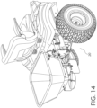
- FIGS. 12-14 show the implement attachment system 20 in use with various implements, such as a cargo carrier in FIG. 12 , a sprayer in FIG. 13 , and a spreader in FIG. 14 .
- implements such as a cargo carrier in FIG. 12 , a sprayer in FIG. 13 , and a spreader in FIG. 14 .
- other implements are also contemplated. Additionally, some of the implements can be used in combination with one another.
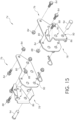
- FIG. 15 structure for a fast attach apparatus or implement attachment system 74 for a front-end of a lawn maintenance vehicle (not shown) will be described.
- at least two attachment clips 76 are located on alternate sides of the longitudinal centerline of the lawn maintenance vehicle proximate to a front end of the lawn maintenance vehicle.
- Each clip 76 is fastened to a portion of the lawn maintenance vehicle.
- the attachment points can be on the frame of the lawn maintenance vehicle.
- each clip 76 can define a cavity 78.
- the cavity 78 may face forward and be configured to cooperatively interact with a portion of an implement (best seen in FIG. 17 ).
- the clip 76 can include a flat bracket 80 that is connected to the frame of the lawn maintenance vehicle.
- the flat bracket 80 is attached with threaded fasteners 84 as shown.
- the flat bracket 80 can be welded to the frame for a more permanent attachment method. Any suitable attachment method is contemplated.
- the clip 76 can further include a receiver bracket 86 such that the flat bracket 80 and the receiver bracket form the cavity 78 that is previously described.
- the receiver bracket 86 can be attached to the flat bracket by threaded fasteners 88 as shown. Other attachment methods are also acceptable.
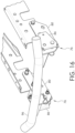
- the receiver bracket 86 defines at least one aperture 90, wherein the aperture 90 is configured to cooperate with a pin 94.
- the pin 94 is configured to pass through the aperture 90 and through a portion of the implement to secure the associated implement to the lawn maintenance vehicle. In many cases, the pin 94 is inserted and removed without an associated hand tool.
- the pin 94 can be translatably attachable to the implement or the clip 76. The operator can then move the pin 94 or pins and removably attach the implement to the lawn maintenance vehicle.
- the pin 94 can be a clevis pin, or any other suitable pin.
- the pin 94 may be a spring-located pin that is urged out of the way by an operator, the implement is put in place, and then the operator releases the pin to have it move back into a position that constitutes a locked position for the implement.
- the clips 76 are attached to a bumper 96 rather than the frame of the lawn maintenance vehicle, and the bumper 96 may be removably attached to the lawn maintenance vehicle.
- the clips 76 are again shown attached to the bumper 96 and a brush guard implement 98 is shown in preparation for attachment to the clips 76.
- the brush guard implement 98 is moved into place in the direction of arrows 100.
- the cavity 78 faces forward and is configured to cooperatively interact with a portion 104 of the brush guard implement 98.
- the portion 104 is configured to be the same general shape and size, albeit slightly smaller, than the cavity 78 to encourage a relatively snug fit between the clips 76 and the implement.
- any number of suitable implements can be used in conjunction with the present disclosure including, but not limited to, a tractor lift, a brush guard, de-thatcher, snow plow, etc. Additionally, the implement may be placed proximate to the front end of the lawn maintenance vehicle prior to attachment.
- the implement attachment system includes one of a post or an aperture located on the plate.
- the post or aperture interacts with the opposite structure (post or aperture) located on the lawn maintenance vehicle.
- the implement attachment system 74 for a lawn maintenance includes a lifting device that attaches to the implement attachment system 74 and is configured to raise the front end of the lawn maintenance vehicle to ease underbody work on the lawn maintenance vehicle.
- the described implement attachment system can provide several benefits.
- the structure can provide a convenient, quick, and inexpensive way to attach implements to a lawn maintenance vehicle without the use of separate hand tools such as screwdrivers, ratchet sets, wrenches, etc.
- the structure described can also provide a relatively strong connection between an implement and the lawn maintenance vehicle in comparison to other attachment methods and structures.
Landscapes
- Life Sciences & Earth Sciences (AREA)
- Engineering & Computer Science (AREA)
- Mechanical Engineering (AREA)
- Environmental Sciences (AREA)
- Zoology (AREA)
- Soil Sciences (AREA)
- Body Structure For Vehicles (AREA)
Claims (5)
- Geräteanbringungssystem (20) für ein Rasenpflegefahrzeug (24), umfassend:eine Gerätemontieranordnung (26), wobei die Gerätemontieranordnung kastenartig ist und einen Haken (28) definiert, der so konfiguriert ist, dass er mit Befestigungselementen (30), die sich am Rasenpflegefahrzeug befinden, zusammenwirkt;einen Stift (40), wobei der Stift an der Gerätemontieranordnung angebracht ist und der Stift sich von der Gerätemontieranordnung in eine Abwärtsrichtung erstreckt, wobei der Stift so konfiguriert ist, dass er mit einer Öffnung (44) zusammenwirkt, die von einem Abschnitt eines zugehörigen Rahmens (38), der sich am Rasenpflegefahrzeug befindet, definiert wird;ein elastisches Kraftelement (54), wobei das elastische Kraftelement an der Gerätemontieranordnung angebracht ist; undeine Riegelstange (56), wobei die Riegelstange an dem elastischen Kraftelement angebracht ist und die Riegelstange gleitend an der Gerätemontieranordnung angebracht ist;wobei die Riegelstange (56) einen gekrümmten Griff (64) beinhaltet, der gekrümmte Griff so konfiguriert ist, dass er die Riegelstange in einer Freigabeposition gegen eine Kraft hält, die von dem elastischen Kraftelement (54) bereitgestellt wird, wenn sich der gekrümmte Griff in einer ersten gedrehten Position befindet, undwobei der gekrümmte Griff (64) so konfiguriert ist, dass er die Riegelstange in eine Eingriffsposition freigibt, wenn sich der gekrümmte Griff in einer zweiten gedrehten Position befindet,dadurch gekennzeichnet, dass sich der gekrümmte Griff (64) mit einer Rückseite (66) der kastenartigen Gerätemontieranordnung (26) in Kontakt befindet, wenn sich der gekrümmte Griff in der ersten gedrehten Position befindet, um die Riegelstange durch Verhindern, dass der gekrümmte Griff (64) zum Rasenpflegefahrzeug (24) hin gedrückt wird, in der Freigabeposition zu halten.
- Geräteanbringungssystem nach Anspruch 1, wobei die Riegelstange (56) weiter ein gegabeltes Ende (58) beinhaltet, das gegabelte Ende so konfiguriert ist, dass es mit einem Befestigungselement (30) zusammenwirkt, das sich am zugehörigen Rahmen befindet, um zu helfen, das Geräteanbringungssystem am Rasenpflegefahrzeug zu sichern.
- Geräteanbringungssystem nach einem der Ansprüche 1-2, wobei das elastische Kraftelement (54) eine Schraubenfeder ist.
- Geräteanbringungssystem nach einem der Ansprüche 1-3, wobei die Riegelstange (56) so konfiguriert ist, dass sie sich um eine Längsachse dreht.
- Rasenpflegefahrzeug (24) und Geräteanbringungssystem (20) nach einem vorstehenden Anspruch, wobei sich das Geräteanbringungssystem (20) an einer Rückseite des Rasenpflegefahrzeugs (24) befindet.
Applications Claiming Priority (2)
| Application Number | Priority Date | Filing Date | Title |
|---|---|---|---|
| US201662397569P | 2016-09-21 | 2016-09-21 | |
| PCT/US2017/052826 WO2018057816A1 (en) | 2016-09-21 | 2017-09-21 | Fast attach implement structure |
Publications (2)
| Publication Number | Publication Date |
|---|---|
| EP3515166A1 EP3515166A1 (de) | 2019-07-31 |
| EP3515166B1 true EP3515166B1 (de) | 2024-10-30 |
Family
ID=60043290
Family Applications (1)
| Application Number | Title | Priority Date | Filing Date |
|---|---|---|---|
| EP17781241.9A Active EP3515166B1 (de) | 2016-09-21 | 2017-09-21 | Vorrichtungsstruktur mit schneller befestigung |
Country Status (4)
| Country | Link |
|---|---|
| US (1) | US20180125008A1 (de) |
| EP (1) | EP3515166B1 (de) |
| CA (1) | CA3041632C (de) |
| WO (1) | WO2018057816A1 (de) |
Families Citing this family (4)
| Publication number | Priority date | Publication date | Assignee | Title |
|---|---|---|---|---|
| US10899284B2 (en) * | 2018-07-19 | 2021-01-26 | Timothy J Descoteaux | Vehicle mounted foldable carrying system |
| US12305680B2 (en) * | 2020-12-21 | 2025-05-20 | Kubota Corporation | Locking bracket and methods of using the same |
| EP4043248A3 (de) * | 2021-02-16 | 2022-11-23 | D.S. Raider Ltd | Verbindungsvorrichtung zum verbinden eines fahrzeugs mit einem anderen fahrzeug, motorisiertes schleppfahrzeug und mit mehreren zusätzlichen fahrzeugen modular verbindbares fahrzeug |
| WO2024063796A1 (en) * | 2022-09-21 | 2024-03-28 | Husqvarna Ab | Movable storage assembly for a riding lawn care vehicle |
Family Cites Families (12)
| Publication number | Priority date | Publication date | Assignee | Title |
|---|---|---|---|---|
| CH293841A (fr) * | 1951-07-16 | 1953-10-15 | Wyss Hans Rudolf | Dispositif d'accrochage d'un bâti à un véhicule. |
| AT309515B (de) * | 1969-08-29 | 1973-08-27 | Kahlbacher Anton | Verriegelungseinrichtung für ein Anbaugerät |
| US3949540A (en) * | 1974-08-02 | 1976-04-13 | The Toro Company | Mower discharge interlock apparatus |
| US4484760A (en) * | 1982-09-30 | 1984-11-27 | Rach Lester G | Remote control hitch |
| US4596347A (en) * | 1985-06-17 | 1986-06-24 | Hite Francis D | Rear mounted utility box with a dumping pivot for a lawn and garden tractor |
| US4688819A (en) * | 1986-08-01 | 1987-08-25 | Deere & Company | Hitch |
| US5082065A (en) * | 1990-08-15 | 1992-01-21 | Support Services International, Inc. | Quick attach implement coupler |
| US6138770A (en) * | 1998-01-26 | 2000-10-31 | Kayser; Howard H. | Lawn tractor load-carrying hitch/frame and spraying apparatus |
| US6557333B2 (en) * | 2001-07-10 | 2003-05-06 | Deere & Company | Material collector mounting system |
| US6988560B2 (en) * | 2003-10-29 | 2006-01-24 | Cnh America Llc | Quick attachment system |
| JP4559778B2 (ja) * | 2004-06-25 | 2010-10-13 | 株式会社クボタ | 草刈機の集草装置 |
| US7908837B2 (en) * | 2008-05-07 | 2011-03-22 | Exmark Mfg. Co., Inc. | Grass collector mounting system |
-
2017
- 2017-09-21 EP EP17781241.9A patent/EP3515166B1/de active Active
- 2017-09-21 CA CA3041632A patent/CA3041632C/en active Active
- 2017-09-21 US US15/712,063 patent/US20180125008A1/en not_active Abandoned
- 2017-09-21 WO PCT/US2017/052826 patent/WO2018057816A1/en not_active Ceased
Also Published As
| Publication number | Publication date |
|---|---|
| EP3515166A1 (de) | 2019-07-31 |
| WO2018057816A1 (en) | 2018-03-29 |
| US20180125008A1 (en) | 2018-05-10 |
| CA3041632A1 (en) | 2018-03-29 |
| CA3041632C (en) | 2021-12-14 |
Similar Documents
| Publication | Publication Date | Title |
|---|---|---|
| EP3515166B1 (de) | Vorrichtungsstruktur mit schneller befestigung | |
| US8371603B2 (en) | Maximum security/maximum versatility ball mount assembly | |
| US8840130B2 (en) | Maximum security/maximum versatility ball mount assembly | |
| US8226107B2 (en) | Maximum security/maximum versatility ball mount assembly | |
| CA2852125C (en) | Hitch assembly for truck frame with integrated hitch mounting structure | |
| US20150021371A1 (en) | Cargo accessory folding mechanism | |
| US20100201100A1 (en) | Hitch adapter | |
| US11890904B2 (en) | Safety chain tie down apparatus | |
| US2877025A (en) | Detachable trailer hitch | |
| CN104334376B (zh) | 用于车辆牵引组件的自动锁定系统 | |
| US4210210A (en) | Quick mounting mechanism for agricultural implement | |
| US20120217725A1 (en) | Dual tow ball coupling apparatus | |
| CA2935507C (en) | Fifth wheel ball hitch | |
| US4193456A (en) | Biased agricultural implement | |
| US7686277B2 (en) | Tool support apparatus | |
| US11926293B2 (en) | Mounting mechanism to enable hitching a tool with the frame of a utility vehicle | |
| US4799555A (en) | Chisel plow mounting assembly | |
| US10161106B2 (en) | Platform assembly for a ground engaging tool | |
| US2678222A (en) | Drawbar lock | |
| JP5388687B2 (ja) | 作業機 | |
| US4883285A (en) | Removable trailer hitch | |
| US20100051729A1 (en) | Rear implement for a vehicle and method of exchanging rear implements | |
| US8814197B2 (en) | Drop-down tilt stop assembly for fifth wheel assembly | |
| US20090230657A1 (en) | Hitching Mechanism | |
| EP1096848B1 (de) | Geräteanschlussvorrichtung und -verfahren |
Legal Events
| Date | Code | Title | Description |
|---|---|---|---|
| STAA | Information on the status of an ep patent application or granted ep patent |
Free format text: STATUS: UNKNOWN |
|
| STAA | Information on the status of an ep patent application or granted ep patent |
Free format text: STATUS: THE INTERNATIONAL PUBLICATION HAS BEEN MADE |
|
| PUAI | Public reference made under article 153(3) epc to a published international application that has entered the european phase |
Free format text: ORIGINAL CODE: 0009012 |
|
| STAA | Information on the status of an ep patent application or granted ep patent |
Free format text: STATUS: REQUEST FOR EXAMINATION WAS MADE |
|
| 17P | Request for examination filed |
Effective date: 20190423 |
|
| AK | Designated contracting states |
Kind code of ref document: A1 Designated state(s): AL AT BE BG CH CY CZ DE DK EE ES FI FR GB GR HR HU IE IS IT LI LT LU LV MC MK MT NL NO PL PT RO RS SE SI SK SM TR |
|
| AX | Request for extension of the european patent |
Extension state: BA ME |
|
| DAV | Request for validation of the european patent (deleted) | ||
| DAX | Request for extension of the european patent (deleted) | ||
| STAA | Information on the status of an ep patent application or granted ep patent |
Free format text: STATUS: EXAMINATION IS IN PROGRESS |
|
| 17Q | First examination report despatched |
Effective date: 20210909 |
|
| GRAP | Despatch of communication of intention to grant a patent |
Free format text: ORIGINAL CODE: EPIDOSNIGR1 |
|
| STAA | Information on the status of an ep patent application or granted ep patent |
Free format text: STATUS: GRANT OF PATENT IS INTENDED |
|
| INTG | Intention to grant announced |
Effective date: 20240105 |
|
| GRAJ | Information related to disapproval of communication of intention to grant by the applicant or resumption of examination proceedings by the epo deleted |
Free format text: ORIGINAL CODE: EPIDOSDIGR1 |
|
| STAA | Information on the status of an ep patent application or granted ep patent |
Free format text: STATUS: EXAMINATION IS IN PROGRESS |
|
| INTC | Intention to grant announced (deleted) | ||
| GRAP | Despatch of communication of intention to grant a patent |
Free format text: ORIGINAL CODE: EPIDOSNIGR1 |
|
| STAA | Information on the status of an ep patent application or granted ep patent |
Free format text: STATUS: GRANT OF PATENT IS INTENDED |
|
| INTG | Intention to grant announced |
Effective date: 20240503 |
|
| GRAS | Grant fee paid |
Free format text: ORIGINAL CODE: EPIDOSNIGR3 |
|
| GRAA | (expected) grant |
Free format text: ORIGINAL CODE: 0009210 |
|
| STAA | Information on the status of an ep patent application or granted ep patent |
Free format text: STATUS: THE PATENT HAS BEEN GRANTED |
|
| AK | Designated contracting states |
Kind code of ref document: B1 Designated state(s): AL AT BE BG CH CY CZ DE DK EE ES FI FR GB GR HR HU IE IS IT LI LT LU LV MC MK MT NL NO PL PT RO RS SE SI SK SM TR |
|
| REG | Reference to a national code |
Ref country code: GB Ref legal event code: FG4D |
|
| REG | Reference to a national code |
Ref country code: CH Ref legal event code: EP |
|
| P01 | Opt-out of the competence of the unified patent court (upc) registered |
Free format text: CASE NUMBER: APP_52696/2024 Effective date: 20240919 |
|
| REG | Reference to a national code |
Ref country code: IE Ref legal event code: FG4D |
|
| REG | Reference to a national code |
Ref country code: DE Ref legal event code: R096 Ref document number: 602017085789 Country of ref document: DE |
|
| REG | Reference to a national code |
Ref country code: LT Ref legal event code: MG9D |
|
| REG | Reference to a national code |
Ref country code: NL Ref legal event code: MP Effective date: 20241030 |
|
| PG25 | Lapsed in a contracting state [announced via postgrant information from national office to epo] |
Ref country code: HR Free format text: LAPSE BECAUSE OF FAILURE TO SUBMIT A TRANSLATION OF THE DESCRIPTION OR TO PAY THE FEE WITHIN THE PRESCRIBED TIME-LIMIT Effective date: 20241030 Ref country code: IS Free format text: LAPSE BECAUSE OF FAILURE TO SUBMIT A TRANSLATION OF THE DESCRIPTION OR TO PAY THE FEE WITHIN THE PRESCRIBED TIME-LIMIT Effective date: 20250228 Ref country code: PT Free format text: LAPSE BECAUSE OF FAILURE TO SUBMIT A TRANSLATION OF THE DESCRIPTION OR TO PAY THE FEE WITHIN THE PRESCRIBED TIME-LIMIT Effective date: 20250228 |
|
| PG25 | Lapsed in a contracting state [announced via postgrant information from national office to epo] |
Ref country code: FI Free format text: LAPSE BECAUSE OF FAILURE TO SUBMIT A TRANSLATION OF THE DESCRIPTION OR TO PAY THE FEE WITHIN THE PRESCRIBED TIME-LIMIT Effective date: 20241030 Ref country code: NL Free format text: LAPSE BECAUSE OF FAILURE TO SUBMIT A TRANSLATION OF THE DESCRIPTION OR TO PAY THE FEE WITHIN THE PRESCRIBED TIME-LIMIT Effective date: 20241030 |
|
| REG | Reference to a national code |
Ref country code: AT Ref legal event code: MK05 Ref document number: 1735945 Country of ref document: AT Kind code of ref document: T Effective date: 20241030 |
|
| PG25 | Lapsed in a contracting state [announced via postgrant information from national office to epo] |
Ref country code: BG Free format text: LAPSE BECAUSE OF FAILURE TO SUBMIT A TRANSLATION OF THE DESCRIPTION OR TO PAY THE FEE WITHIN THE PRESCRIBED TIME-LIMIT Effective date: 20241030 |
|
| PG25 | Lapsed in a contracting state [announced via postgrant information from national office to epo] |
Ref country code: ES Free format text: LAPSE BECAUSE OF FAILURE TO SUBMIT A TRANSLATION OF THE DESCRIPTION OR TO PAY THE FEE WITHIN THE PRESCRIBED TIME-LIMIT Effective date: 20241030 |
|
| PG25 | Lapsed in a contracting state [announced via postgrant information from national office to epo] |
Ref country code: NO Free format text: LAPSE BECAUSE OF FAILURE TO SUBMIT A TRANSLATION OF THE DESCRIPTION OR TO PAY THE FEE WITHIN THE PRESCRIBED TIME-LIMIT Effective date: 20250130 |
|
| PG25 | Lapsed in a contracting state [announced via postgrant information from national office to epo] |
Ref country code: GR Free format text: LAPSE BECAUSE OF FAILURE TO SUBMIT A TRANSLATION OF THE DESCRIPTION OR TO PAY THE FEE WITHIN THE PRESCRIBED TIME-LIMIT Effective date: 20250131 Ref country code: LV Free format text: LAPSE BECAUSE OF FAILURE TO SUBMIT A TRANSLATION OF THE DESCRIPTION OR TO PAY THE FEE WITHIN THE PRESCRIBED TIME-LIMIT Effective date: 20241030 Ref country code: AT Free format text: LAPSE BECAUSE OF FAILURE TO SUBMIT A TRANSLATION OF THE DESCRIPTION OR TO PAY THE FEE WITHIN THE PRESCRIBED TIME-LIMIT Effective date: 20241030 |
|
| PG25 | Lapsed in a contracting state [announced via postgrant information from national office to epo] |
Ref country code: PL Free format text: LAPSE BECAUSE OF FAILURE TO SUBMIT A TRANSLATION OF THE DESCRIPTION OR TO PAY THE FEE WITHIN THE PRESCRIBED TIME-LIMIT Effective date: 20241030 |
|
| PG25 | Lapsed in a contracting state [announced via postgrant information from national office to epo] |
Ref country code: RS Free format text: LAPSE BECAUSE OF FAILURE TO SUBMIT A TRANSLATION OF THE DESCRIPTION OR TO PAY THE FEE WITHIN THE PRESCRIBED TIME-LIMIT Effective date: 20250130 |
|
| PG25 | Lapsed in a contracting state [announced via postgrant information from national office to epo] |
Ref country code: SM Free format text: LAPSE BECAUSE OF FAILURE TO SUBMIT A TRANSLATION OF THE DESCRIPTION OR TO PAY THE FEE WITHIN THE PRESCRIBED TIME-LIMIT Effective date: 20241030 |
|
| PG25 | Lapsed in a contracting state [announced via postgrant information from national office to epo] |
Ref country code: DK Free format text: LAPSE BECAUSE OF FAILURE TO SUBMIT A TRANSLATION OF THE DESCRIPTION OR TO PAY THE FEE WITHIN THE PRESCRIBED TIME-LIMIT Effective date: 20241030 |
|
| PG25 | Lapsed in a contracting state [announced via postgrant information from national office to epo] |
Ref country code: EE Free format text: LAPSE BECAUSE OF FAILURE TO SUBMIT A TRANSLATION OF THE DESCRIPTION OR TO PAY THE FEE WITHIN THE PRESCRIBED TIME-LIMIT Effective date: 20241030 |
|
| PG25 | Lapsed in a contracting state [announced via postgrant information from national office to epo] |
Ref country code: RO Free format text: LAPSE BECAUSE OF FAILURE TO SUBMIT A TRANSLATION OF THE DESCRIPTION OR TO PAY THE FEE WITHIN THE PRESCRIBED TIME-LIMIT Effective date: 20241030 |
|
| PG25 | Lapsed in a contracting state [announced via postgrant information from national office to epo] |
Ref country code: SK Free format text: LAPSE BECAUSE OF FAILURE TO SUBMIT A TRANSLATION OF THE DESCRIPTION OR TO PAY THE FEE WITHIN THE PRESCRIBED TIME-LIMIT Effective date: 20241030 |
|
| PG25 | Lapsed in a contracting state [announced via postgrant information from national office to epo] |
Ref country code: CZ Free format text: LAPSE BECAUSE OF FAILURE TO SUBMIT A TRANSLATION OF THE DESCRIPTION OR TO PAY THE FEE WITHIN THE PRESCRIBED TIME-LIMIT Effective date: 20241030 |
|
| PG25 | Lapsed in a contracting state [announced via postgrant information from national office to epo] |
Ref country code: IT Free format text: LAPSE BECAUSE OF FAILURE TO SUBMIT A TRANSLATION OF THE DESCRIPTION OR TO PAY THE FEE WITHIN THE PRESCRIBED TIME-LIMIT Effective date: 20241030 |
|
| REG | Reference to a national code |
Ref country code: DE Ref legal event code: R097 Ref document number: 602017085789 Country of ref document: DE |
|
| PLBE | No opposition filed within time limit |
Free format text: ORIGINAL CODE: 0009261 |
|
| STAA | Information on the status of an ep patent application or granted ep patent |
Free format text: STATUS: NO OPPOSITION FILED WITHIN TIME LIMIT |
|
| PG25 | Lapsed in a contracting state [announced via postgrant information from national office to epo] |
Ref country code: SE Free format text: LAPSE BECAUSE OF FAILURE TO SUBMIT A TRANSLATION OF THE DESCRIPTION OR TO PAY THE FEE WITHIN THE PRESCRIBED TIME-LIMIT Effective date: 20241030 |
|
| 26N | No opposition filed |
Effective date: 20250731 |
|
| PGFP | Annual fee paid to national office [announced via postgrant information from national office to epo] |
Ref country code: DE Payment date: 20250919 Year of fee payment: 9 |
|
| PGFP | Annual fee paid to national office [announced via postgrant information from national office to epo] |
Ref country code: GB Payment date: 20250923 Year of fee payment: 9 |
|
| PGFP | Annual fee paid to national office [announced via postgrant information from national office to epo] |
Ref country code: FR Payment date: 20250924 Year of fee payment: 9 |