EP3514922B2 - Fractional slot multi winding set electrical machine - Google Patents
Fractional slot multi winding set electrical machine Download PDFInfo
- Publication number
- EP3514922B2 EP3514922B2 EP18152223.6A EP18152223A EP3514922B2 EP 3514922 B2 EP3514922 B2 EP 3514922B2 EP 18152223 A EP18152223 A EP 18152223A EP 3514922 B2 EP3514922 B2 EP 3514922B2
- Authority
- EP
- European Patent Office
- Prior art keywords
- phase
- winding set
- winding
- slots
- sections
- Prior art date
- Legal status (The legal status is an assumption and is not a legal conclusion. Google has not performed a legal analysis and makes no representation as to the accuracy of the status listed.)
- Active
Links
- 238000004804 winding Methods 0.000 title claims description 121
- 238000001816 cooling Methods 0.000 claims description 25
- 230000009977 dual effect Effects 0.000 claims description 19
- 238000000034 method Methods 0.000 claims description 8
- 230000001965 increasing effect Effects 0.000 description 10
- 230000005347 demagnetization Effects 0.000 description 8
- 230000003071 parasitic effect Effects 0.000 description 7
- 230000001276 controlling effect Effects 0.000 description 5
- 230000008901 benefit Effects 0.000 description 4
- 230000000875 corresponding effect Effects 0.000 description 4
- 230000007423 decrease Effects 0.000 description 3
- 230000010363 phase shift Effects 0.000 description 3
- 239000002826 coolant Substances 0.000 description 2
- 230000009286 beneficial effect Effects 0.000 description 1
- 238000010276 construction Methods 0.000 description 1
- 239000012809 cooling fluid Substances 0.000 description 1
- 230000003247 decreasing effect Effects 0.000 description 1
- 230000001419 dependent effect Effects 0.000 description 1
- 238000010586 diagram Methods 0.000 description 1
- 230000004907 flux Effects 0.000 description 1
- 230000001939 inductive effect Effects 0.000 description 1
- 230000002427 irreversible effect Effects 0.000 description 1
- 238000004519 manufacturing process Methods 0.000 description 1
- 230000011218 segmentation Effects 0.000 description 1
Images


Classifications
-
- H—ELECTRICITY
- H02—GENERATION; CONVERSION OR DISTRIBUTION OF ELECTRIC POWER
- H02K—DYNAMO-ELECTRIC MACHINES
- H02K3/00—Details of windings
- H02K3/04—Windings characterised by the conductor shape, form or construction, e.g. with bar conductors
- H02K3/28—Layout of windings or of connections between windings
-
- H—ELECTRICITY
- H02—GENERATION; CONVERSION OR DISTRIBUTION OF ELECTRIC POWER
- H02K—DYNAMO-ELECTRIC MACHINES
- H02K1/00—Details of the magnetic circuit
- H02K1/06—Details of the magnetic circuit characterised by the shape, form or construction
- H02K1/12—Stationary parts of the magnetic circuit
- H02K1/14—Stator cores with salient poles
- H02K1/146—Stator cores with salient poles consisting of a generally annular yoke with salient poles
- H02K1/148—Sectional cores
-
- H—ELECTRICITY
- H02—GENERATION; CONVERSION OR DISTRIBUTION OF ELECTRIC POWER
- H02K—DYNAMO-ELECTRIC MACHINES
- H02K21/00—Synchronous motors having permanent magnets; Synchronous generators having permanent magnets
- H02K21/12—Synchronous motors having permanent magnets; Synchronous generators having permanent magnets with stationary armatures and rotating magnets
- H02K21/22—Synchronous motors having permanent magnets; Synchronous generators having permanent magnets with stationary armatures and rotating magnets with magnets rotating around the armatures, e.g. flywheel magnetos
-
- H—ELECTRICITY
- H02—GENERATION; CONVERSION OR DISTRIBUTION OF ELECTRIC POWER
- H02K—DYNAMO-ELECTRIC MACHINES
- H02K2213/00—Specific aspects, not otherwise provided for and not covered by codes H02K2201/00 - H02K2211/00
- H02K2213/12—Machines characterised by the modularity of some components
-
- H—ELECTRICITY
- H02—GENERATION; CONVERSION OR DISTRIBUTION OF ELECTRIC POWER
- H02K—DYNAMO-ELECTRIC MACHINES
- H02K7/00—Arrangements for handling mechanical energy structurally associated with dynamo-electric machines, e.g. structural association with mechanical driving motors or auxiliary dynamo-electric machines
- H02K7/18—Structural association of electric generators with mechanical driving motors, e.g. with turbines
- H02K7/1807—Rotary generators
- H02K7/1823—Rotary generators structurally associated with turbines or similar engines
- H02K7/183—Rotary generators structurally associated with turbines or similar engines wherein the turbine is a wind turbine
- H02K7/1838—Generators mounted in a nacelle or similar structure of a horizontal axis wind turbine
-
- Y—GENERAL TAGGING OF NEW TECHNOLOGICAL DEVELOPMENTS; GENERAL TAGGING OF CROSS-SECTIONAL TECHNOLOGIES SPANNING OVER SEVERAL SECTIONS OF THE IPC; TECHNICAL SUBJECTS COVERED BY FORMER USPC CROSS-REFERENCE ART COLLECTIONS [XRACs] AND DIGESTS
- Y02—TECHNOLOGIES OR APPLICATIONS FOR MITIGATION OR ADAPTATION AGAINST CLIMATE CHANGE
- Y02E—REDUCTION OF GREENHOUSE GAS [GHG] EMISSIONS, RELATED TO ENERGY GENERATION, TRANSMISSION OR DISTRIBUTION
- Y02E10/00—Energy generation through renewable energy sources
- Y02E10/70—Wind energy
- Y02E10/72—Wind turbines with rotation axis in wind direction
Definitions
- the present invention relates to a fractional slot dual three-phase winding set electrical machine, relates to a wind turbine and further relates to a method for controlling a fractional slot dual three-phase winding set electrical machine or a wind turbine.
- An electrical machine may comprise a stator comprising a stator yoke having plural teeth alternating with plural slots. Furthermore, the electrical machine may comprise a rotor on which plural permanent magnets are mounted. The rotor may be rotatably supported to allow rotation of the rotor relative to the stator, while a gap is present between ends of the teeth of the stator and the poles of the rotor. In the slots of the stator, one or more winding sets may be arranged, in particular in multiple turns.
- a fractional slot topology refers to a configuration, wherein the ratio of the number of slots divided by the number of poles is not an integer but a rational number. It has been observed that fractional slot topologies may be inherently prone to parasitic air gap sub-harmonic frequencies which may cause issues such as undesirable air gap forces and losses within the rotor house.
- the fractional slot concentrated winding (FSCW) generator may show a beneficial electromagnetic performance, the concentrated winding may also lead to a decrease in cooling surface area when compared to integer slot distributed winding topology electrical machines due to the reduction in end winding surface area.
- the magnets of a permanent magnet FSCW may be more susceptible to demagnetization during fault conditions (such as short-circuits) than an equivalent distributed winding machine.
- the electrical machine is composed of at least two sections which form a ring, i.e. a whole circumference in the circumferential direction.
- the electrical machine may be composed of at least two or at least three or even more sections which when assembled form a ring, i.e. a whole circumference in the circumferential direction.
- the stator portion and the rotor portion in each section may be separate from each other (not being connected to each other) to allow the assembled machine to rotate the rotor relative to the stator. All sections may be configured in a same manner or at least in a similar manner.
- the electrical machine may be configured as a generator for generating electrical energy or a motor for producing mechanical rotation.
- the electrical machine may comprise in particular a relatively high number of sections which may contribute for decreasing parasitic air gap sub-harmonic frequencies and/or which may contribute to reduce the demagnetization of the permanent magnets during fault conditions and may also contribute to improving the cooling.
- the number of slots is greater than or equal to 9 and the number of poles is greater than or equal to 10.
- the number of slots is 12 and the number of poles is 10 or the number of slots is 9 and the number of poles is 12 or the number of slots is 9 and the number of poles is 8 or the number of slots is 9 and the number of poles is 10 or the number of slots is 12 and the number of poles is 14.
- Other configurations are possible, e.g. multiples of these slot/pole numbers.
- the at least one second winding set comprises exactly one second winding set, wherein in particular one wire of one phase (e.g. A1+) of the first winding set and one wire of one phase (e.g. A2-) of the second winding sets are at least partly arranged in one slot of the plural slots side by side in the circumferential direction.
- the winding scheme may be a concentrated winding scheme.
- the dual winding set electrical machine may have the advantage to be of simple construction, while allowing segmentation of the electrical machine for transportation, simplifying the transportation.
- a wire of a phase of the first winding set may be arranged as well as a wire of a phase of the second winding set.
- the two wires commonly arranged in one slot may be insulated from each other appropriately.
- the turning direction of the one wire of the one phase of the first winding set may be opposite to the winding direction of the one wire of one phase of the second winding set.
- Other winding topologies may be possible.
- each winding set comprises a common connec-tion point at which one respective end of all wires of this winding set are connected with each other.
- the common connection point may also be referred to as a star con-nection point.
- other ends of all wires of one phase for one wind-ing set are connected with each other and are connect-able to a converter input of the respective phase for the respective winding set.
- a number of wires of each of the winding sets is equal to the number of sections times a number of phas-es, wherein the number of phases is three.
- the electrical machine further comprises a cooling system including cooling ducts at least within the teeth (in particular running along a radial direction), wherein a cooling capacity is scaled down for higher number of sections.
- a cooling system including cooling ducts at least within the teeth (in particular running along a radial direction), wherein a cooling capacity is scaled down for higher number of sections.
- a wind turbine comprising a rotor shaft with plural rotor blades and a machine according to one of the preceding embodiments which has the rotor mechanically coupled with the rotor shaft.
- the rotor of the machine rotates thereby inducing electrical currents in the multiple winding sets, thereby generating electrical energy.
- a method for controlling a fractional slot dual three-phase winding set electrical machine or a wind turbine comprising controlling a first AC-DC converter connected to the first winding set and a second AC-DC converter connected to the second winding set such that first electric currents carried in the first winding set are (e.g. 30° for a dual machine) phase shifted relative to respective second electric currents carried in the second winding set.
- a first current of an A phase of the first three-phase winding set is generated to be essentially 30° phase shifted relative to a second current of an A phase of the second three-phase winding set
- a first current of a B phase of the first three-phase winding set is generated to be essentially 30° phase shifted relative to a second current of a B phase of the second three-phase winding set
- a first current of a C phase of the first three-phase winding set is generated to be essentially 30° phase shifted relative to a second current of a C phase of the second three-phase winding set.
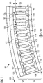
- Fig. 1 schematically illustrates one section 100 of a fractional slot dual three-phase winding set electrical machine according to an embodiment of the present invention in a sectional view having an axial direction 101 being perpendicular to the drawing plane. At least two, for example three sections 100 form a whole circumference in the circumferential direction 103 of the fractional slot dual three-phase winding set electrical machine.
- the section 100 is configured as a dual winding set section for the electrical machine, wherein each winding set has three phases.
- the phases are labelled A, B, C and the first winding set and the second winding set are labelled with numbers “1" and "2", respectively.
- the stator portion 102 comprises 12 slots 105 alternating with teeth 107 along the circumferential direction 103.
- the section 100 comprises a first winding set comprising wires for the phases A1, B1 and C1.
- the first winding set comprises a wire 109 for phase A1+ wherein the wire 109 is wound around one of the teeth 107 and occupies about a half of one of the slots 105.
- the wire 109 is wound around the tooth 107 which is labelled "A1+”.
- the wire 109 is then led to another tooth 107 which is labelled "A1-” and is turned around this tooth in the opposite turning direction.
- the wire 109 forms two coils around two teeth (labelled as "A1+” and "A1-").
- One end of the wire 109 is connected with respective ends of all other phases or wires of the first winding set, i.e. the wires 111 and the wire 113 at a common connection point N1, as illustrated in Fig. 2 .
- the wire 111 is first wound around a tooth 107 labelled as "B1-”, led to the tooth labelled "B1+” and turned around this tooth in the opposite direction.
- the wire 113 is turned in one or more winding turns around the tooth 107 labelled as "C1+”, is then led to the tooth labelled "C1-” and is turned around this tooth in the opposite direction.
- the wires 109, 111 and 113 all belong to the first winding set (labelled in Fig. 2 as 125).
- the second winding set (labelled in Fig. 2 as 127) comprises the wire 115 which is wound around the tooth labelled "A2-" which is then led to the tooth which is labelled "A2+” and turned in an opposite direction around this tooth.
- the second winding set further comprises the wires 117 (for phase B2) and the wire 119 (for phase C2).
- the section 100 comprises the stator portion 102 and the (radially outer) rotor portion 104 having a gap g between ends of teeth and poles.
- the rotor portion comprises a number of poles, in the illustrated embodiment poles of ten magnets 121 which are mounted on a ring section 123 which may be supported to rotate relative to the stator portion 102.
- the stator 106 comprises the teeth 107.
- the section 100 illustrated in Fig. 1 further comprises a not in detail illustrated cooling system including cooling fluid ducts within the stator yoke 106 which may comprise an inlet or an outlet 145, 147. Due to a relatively high number of sections 100 comprised in the electrical machine, the cooling surface may be relatively large or larger than conventionally observed. Thereby, the cooling may be improved.
- Fig. 2 schematically illustrates the electrical connectivity of the first winding set 125 and the second winding set 127 for three sections such as section 100 illustrated in Fig. 1 .
- the first winding set 125 comprises for the phase U1 a parallel connection of three series connections of coils which are labelled A1-, A1, A1-', A1', A1-", A1" which are formed by winding the wires 109 (for the first section), 109' (for the second section) and 109" (for the third section), respectively, around teeth as is illustrated for example in Fig. 1 .
- the second winding set 127 comprises for each phase U2, V2, W2 a parallel connection of a series connection of two coils which are formed by winding the wires 115, 117, 119 and the corresponding primed wires around respective teeth.
- connection scheme illustrated in Fig. 2 thus represents a connection scheme of a fractional slot dual three-phase winding set electrical machine having exactly three sections per segment, such as sections as illustrated in Fig. 1 .
- the fractional slot dual three-phase winding set electrical machine has a total of twelve sections or thirteen sections or fourteen sections or fifteen sections or sixteen sections or even a greater number of sections.
- phase connection points 129, 131 and 133 of the first set 125 of windings are connected (as U1, V1 and W1) to respective input terminals of a first AC-DC converter 141.
- phase connection points 135, 137 and 139 may be connected (as U2, V2 and W2) to respective input terminals of a second AC-DC converter 143.
- the AC-DC converters 141, 143 are connected to a control system 142 that is adapted to carry out a method according to an embodiment of the present invention.
- the wire 109 of the first winding set may be comprised in a first section, the wire 109' may be comprised in a second section and the wire 109" may be comprised in a third section of the fractional dual three-phase winding set electrical machine.
- the wire 111 may be comprised in the first section, the wire 111' may be comprised in the second section and the wire 111" may be comprised in the third section of the electrical machine.
- the wire 113 may be comprised in a first section, the wire 113' may be comprised in a second section and the wire 113" may be comprised in a third section of the electrical machine.
- the first winding set comprises thus nine wires which is equal to the number of sections (i.e. three sections) times the number of phases (i.e. three phases).
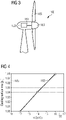
- Fig. 3 schematically illustrates a wind turbine 160 according to an embodiment of the present invention.
- the wind turbine 160 comprises a rotor shaft 161 having a hub 163 at which plural rotor blades 165 are connected.
- the wind turbine 160 further comprises an electrical machine 150 which may comprise at least one section, for example three, 100 as illustrated in Fig. 1 which form a whole circumference in the circumferential direction.
- the electrical machine 150 may for example be controlled according to a method for controlling a fractional slot dual three-phase winding set electrical machine according to an embodiment of the present invention.
- the first AC-DC converter 141 is connected to the first winding set 125 and the second AC-DC converter 143 is connected to the second winding set, as illustrated in Fig. 2 .
- the control is such that the first electric currents 171, 173, 175 carried in the first winding set 125 are essentially phase shifted, for example 30°, relative to the respective second electric currents 177, 179 and 181.
- the inherent harmonics and ripple may be eliminated alleviating the parasitic air gap forces and rotor loss issues.
- the 12 slots/10 pole topology in this manner may improve the generator performance due to the improved phase winding factor.
- Using other fractional slot topologies may result in requiring a higher number of multi-phase combinations resulting in added costs in converter system modularity. This technique is also applicable for 12 slots/14 pole rotor combinations.
- the fault current per coil may be reduced. This may be because the number of coils is greater thereby the current per coil may be reduced. Further, this may be due to the parallel arrangement of the 12 s/10 p sections (see Fig. 2 ), therefore the higher number of sections, the lower the fault current per coil may be.
- a lower fault current per coil may equate to a lower demagnetization risk of the permanent magnet poles directly opposite the coil which is in a circuit under fault conditions.
- a simple fractional slot topology of 12 slots and 10 poles is utilized combined with the dual three-phase winding with phase shift to eliminate the parasitic effect of the air gap flux harmonics.
- a simple fractional slot topology of 12 slots and 10 poles is utilized combined with the dual three-phase winding with phase shift to eliminate the parasitic effect of the air gap flux harmonics.
- combined with the increase in the number of 12 s/10 p sections may improve the thermal operation of the generator by increasing the cooling surface area, reducing the demagnetization risk of the magnets as well as reducing the torque ripple.
- Fig. 4 shows that the cooling surface area increases with increasing number of 12 slot/10 pole sections comprised in the electrical machine.
- Fig. 4 demonstrates how the total cooling area of the generator can be increased by increasing the number of 12 s/10 p groups.
- the increase in area is primarily due to the increase in the end-winding area as well as the increase of coil area in the cooling ducts.
- the previously mentioned decrease in peak fault current can also be appreciated in Fig. 5 as a curve 195.
- the peak fault current is the leading factor in magnet irreversible demagnetization.
- the peak fault current decreases according to the curve 195 with increasing number of 12 s/10 p sections comprised in the electrical machine.
Description
- The present invention relates to a fractional slot dual three-phase winding set electrical machine, relates to a wind turbine and further relates to a method for controlling a fractional slot dual three-phase winding set electrical machine or a wind turbine.
- An electrical machine may comprise a stator comprising a stator yoke having plural teeth alternating with plural slots. Furthermore, the electrical machine may comprise a rotor on which plural permanent magnets are mounted. The rotor may be rotatably supported to allow rotation of the rotor relative to the stator, while a gap is present between ends of the teeth of the stator and the poles of the rotor. In the slots of the stator, one or more winding sets may be arranged, in particular in multiple turns.
- A fractional slot topology refers to a configuration, wherein the ratio of the number of slots divided by the number of poles is not an integer but a rational number. It has been observed that fractional slot topologies may be inherently prone to parasitic air gap sub-harmonic frequencies which may cause issues such as undesirable air gap forces and losses within the rotor house. Although the fractional slot concentrated winding (FSCW) generator may show a beneficial electromagnetic performance, the concentrated winding may also lead to a decrease in cooling surface area when compared to integer slot distributed winding topology electrical machines due to the reduction in end winding surface area. Similarly, the magnets of a permanent magnet FSCW may be more susceptible to demagnetization during fault conditions (such as short-circuits) than an equivalent distributed winding machine.
- Thus, there may be a need for a fractional slot dual three-phase winding set electrical machine where parasitic air gap sub-harmonic frequencies are reduced, where effective cooling is achieved and demagnetization during fault conditions is reduced. The document
EP 3 051 670 A1 discloses a winding design for a stator of an electric machine. - This need may be met by the subject matter according to the independent claims. Advantageous em-bodiments of the present invention are described by the dependent claims.
- The electrical machine is composed of at least two sections which form a ring, i.e. a whole circumference in the circumferential direction. Alternatively, the electrical machine may be composed of at least two or at least three or even more sections which when assembled form a ring, i.e. a whole circumference in the circumferential direction. The stator portion and the rotor portion in each section may be separate from each other (not being connected to each other) to allow the assembled machine to rotate the rotor relative to the stator. All sections may be configured in a same manner or at least in a similar manner. The electrical machine may be configured as a generator for generating electrical energy or a motor for producing mechanical rotation. The electrical machine may comprise in particular a relatively high number of sections which may contribute for decreasing parasitic air gap sub-harmonic frequencies and/or which may contribute to reduce the demagnetization of the permanent magnets during fault conditions and may also contribute to improving the cooling.
- According to an embodiment of the present invention, the number of slots is greater than or equal to 9 and the number of poles is greater than or equal to 10. Thereby, technical advantages regarding reduction of undesired frequencies and reduction of demagnetization of the permanent magnets may be achieved.
- According to an embodiment of the present invention, the number of slots is 12 and the number of poles is 10 or the number of slots is 9 and the number of poles is 12 or the number of slots is 9 and the number of poles is 8 or the number of slots is 9 and the number of poles is 10 or the number of slots is 12 and the number of poles is 14. Other configurations are possible, e.g. multiples of these slot/pole numbers.
- According to an embodiment of the present invention, a number of sections is between three to 11 or at least 12 or at least 13 or at least 14 or at least 15 or at least 16 sections or greater. The higher the number of sections, the better parasitic air gap sub-harmonic frequencies may be reduced, demagnetization may be reduced and cooling may be improved.
- According to an embodiment of the present invention, the at least one second winding set comprises exactly one second winding set, wherein in particular one wire of one phase (e.g. A1+) of the first winding set and one wire of one phase (e.g. A2-) of the second winding sets are at least partly arranged in one slot of the plural slots side by side in the circumferential direction. Thereby, a dual electrical machine is provided having exactly two winding sets. In particular, the winding scheme may be a concentrated winding scheme. The dual winding set electrical machine may have the advantage to be of simple construction, while allowing segmentation of the electrical machine for transportation, simplifying the transportation.
- In each of the slots of the stator, a wire of a phase of the first winding set may be arranged as well as a wire of a phase of the second winding set. The two wires commonly arranged in one slot may be insulated from each other appropriately. The turning direction of the one wire of the one phase of the first winding set may be opposite to the winding direction of the one wire of one phase of the second winding set. Other winding topologies may be possible.
- According to an embodiment of the present invention, any wire of any winding set of any phase is wound in at least one turn around a tooth thereby at least partly occupying two slots adjacent to the tooth. In particular, any wire of any winding set of any phase may essentially occupy half of each of the two slots adjacent to the tooth around which this wire is wound. Thereby, a concentrated winding scheme may be supported.
- According to the present invention, each winding set comprises a common connec-tion point at which one respective end of all wires of this winding set are connected with each other. The common connection point may also be referred to as a star con-nection point. Thereby, a star configuration is supported.
- According to the present invention, other ends of all wires of one phase for one wind-ing set are connected with each other and are connect-able to a converter input of the respective phase for the respective winding set.
- For each section the electrical machine comprises for each phase for each winding set at least one series connec-tion of coils, for example two, cor-responding to that phase and which are formed by wind-ing the wire in two opposing directions around two teeth which may be spaced apart in the circumferential direc-tion such that other teeth are in between. The series con-nection of the two coils for each phase for one section may be connected in parallel with a corresponding series connection of two coils of this phase for any of the other sections.
- According to an embodiment of the present invention, a number of wires of each of the winding sets is equal to the number of sections times a number of phas-es, wherein the number of phases is three.
- According to an embodiment of the present invention, the electrical machine further comprises a cooling system including cooling ducts at least within the teeth (in particular running along a radial direction), wherein a cooling capacity is scaled down for higher number of sections. By increasing the number of sections, the cooling surface area may be increased leading to a larger overall cooling surface area and therefore a more efficient transfer of losses from the machine to the cooling medium may be enabled. Thereby, scaling back the required cooling to reduce the costs is enabled.
- According to an embodiment of the present invention it is provided a wind turbine comprising a rotor shaft with plural rotor blades and a machine according to one of the preceding embodiments which has the rotor mechanically coupled with the rotor shaft. Upon rotation of the rotor shaft driven by wind energy, the rotor of the machine rotates thereby inducing electrical currents in the multiple winding sets, thereby generating electrical energy.
- It should be understood that features, individually or in any combination, disclosed, described or explained with respect to a fractional slot dual three-phase winding set electrical machine may also be applied, individually or in any combination, to a method for controlling a fractional slot dual three-phase winding set electrical machine or a wind turbine according to embodiments of the present invention and vice versa.
- According to an embodiment of the present invention it is provided a method for controlling a fractional slot dual three-phase winding set electrical machine or a wind turbine according to one of the preceding claims, comprising controlling a first AC-DC converter connected to the first winding set and a second AC-DC converter connected to the second winding set such that first electric currents carried in the first winding set are (e.g. 30° for a dual machine) phase shifted relative to respective second electric currents carried in the second winding set.
- By achieving a 30° phase shift between the electrical currents of the two winding sets, the inherent harmonics and ripples may be efficiently eliminated alleviating the parasitic air gap forces and rotor loss issues. In particular, when the electrical machine is configured having a 12 slot/10 pole topology, the generator performance due to the improved phase winding factor may be improved. The electrical machine may also have a topology of 12 slots and 14 poles in each section.
- According to an embodiment of the present invention, a first current of an A phase of the first three-phase winding set is generated to be essentially 30° phase shifted relative to a second current of an A phase of the second three-phase winding set, wherein a first current of a B phase of the first three-phase winding set is generated to be essentially 30° phase shifted relative to a second current of a B phase of the second three-phase winding set, wherein a first current of a C phase of the first three-phase winding set is generated to be essentially 30° phase shifted relative to a second current of a C phase of the second three-phase winding set.
- The aspects defined above and further aspects of the present invention are apparent from the examples of embodiment to be described hereinafter and are explained with reference to the examples of embodiment. The invention will be described in more detail hereinafter with reference to examples of embodiment but to which the invention is not limited.
- Embodiments of the present invention are now described with reference to the accompanying drawings. The invention is not limited to the described or illustrated embodiments.
-
Fig. 1 schematically illustrates in a sectional view a section of a fractional slot multi winding set electrical machine according to an embodiment of the present invention; -
Fig. 2 schematically illustrates a circuit diagram of winding sets of a fractional slot multi winding set electrical machine according to an embodiment of the present invention; -
Fig. 3 illustrates a wind turbine according to an embodiment of the present invention; -
Fig. 4 illustrates a graph of a cooling surface area achieved in embodiments of the present invention; -
Fig. 5 illustrates a graph of a fault current as achieved according to embodiments of the present invention; - Fig. 6 illustrates curves of torque ripple as achieved in embodiments of the present invention and
- Fig. 7 illustrates graphs of a torque as observed for embodiments of the present invention.
- The illustration in the drawings is in schematic form. It is noted that in different figures, similar or identical elements are provided with the same reference signs or with reference signs, which are different from the corresponding reference signs only within the first digit.
-
Fig. 1 schematically illustrates onesection 100 of a fractional slot dual three-phase winding set electrical machine according to an embodiment of the present invention in a sectional view having anaxial direction 101 being perpendicular to the drawing plane. At least two, for example threesections 100 form a whole circumference in thecircumferential direction 103 of the fractional slot dual three-phase winding set electrical machine. - In particular, the
section 100 is configured as a dual winding set section for the electrical machine, wherein each winding set has three phases. The phases are labelled A, B, C and the first winding set and the second winding set are labelled with numbers "1" and "2", respectively. Thestator portion 102 comprises 12slots 105 alternating withteeth 107 along thecircumferential direction 103. Furthermore, thesection 100 comprises a first winding set comprising wires for the phases A1, B1 and C1. In particular, the first winding set comprises awire 109 for phase A1+ wherein thewire 109 is wound around one of theteeth 107 and occupies about a half of one of theslots 105. In particular, thewire 109 is wound around thetooth 107 which is labelled "A1+". Thewire 109 is then led to anothertooth 107 which is labelled "A1-" and is turned around this tooth in the opposite turning direction. Thus, thewire 109 forms two coils around two teeth (labelled as "A1+" and "A1-"). - One end of the
wire 109 is connected with respective ends of all other phases or wires of the first winding set, i.e. thewires 111 and thewire 113 at a common connection point N1, as illustrated inFig. 2 . Thewire 111 is first wound around atooth 107 labelled as "B1-", led to the tooth labelled "B1+" and turned around this tooth in the opposite direction. Finally, thewire 113 is turned in one or more winding turns around thetooth 107 labelled as "C1+", is then led to the tooth labelled "C1-" and is turned around this tooth in the opposite direction. Thewires Fig. 2 as 125). - The second winding set (labelled in
Fig. 2 as 127) comprises thewire 115 which is wound around the tooth labelled "A2-" which is then led to the tooth which is labelled "A2+" and turned in an opposite direction around this tooth. The second winding set further comprises the wires 117 (for phase B2) and the wire 119 (for phase C2). - The
section 100 comprises thestator portion 102 and the (radially outer)rotor portion 104 having a gap g between ends of teeth and poles. The rotor portion comprises a number of poles, in the illustrated embodiment poles of tenmagnets 121 which are mounted on aring section 123 which may be supported to rotate relative to thestator portion 102. Thestator 106 comprises theteeth 107. - The
section 100 illustrated inFig. 1 further comprises a not in detail illustrated cooling system including cooling fluid ducts within thestator yoke 106 which may comprise an inlet or anoutlet sections 100 comprised in the electrical machine, the cooling surface may be relatively large or larger than conventionally observed. Thereby, the cooling may be improved. -
Fig. 2 schematically illustrates the electrical connectivity of the first winding set 125 and the second windingset 127 for three sections such assection 100 illustrated inFig. 1 . As can be appreciated fromFig. 2 , the first winding set 125 comprises for the phase U1 a parallel connection of three series connections of coils which are labelled A1-, A1, A1-', A1', A1-", A1" which are formed by winding the wires 109 (for the first section), 109' (for the second section) and 109" (for the third section), respectively, around teeth as is illustrated for example inFig. 1 . Further, the first winding set 125 comprises for the phase V1 a parallel connection of three series connections of coils which are labelled B1-, B1, B1-', B1', B1-", B1" which are formed by winding thewires Fig. 1 . Further, the first winding set 125 comprises for the phase W1 a parallel connection of three series connections of coils which are labelled C1-, C1, C1-', C1', C1-", C1" which are formed by winding thewires Fig. 1 . - Similarly, the second winding set 127 comprises for each phase U2, V2, W2 a parallel connection of a series connection of two coils which are formed by winding the
wires - The connection scheme illustrated in
Fig. 2 thus represents a connection scheme of a fractional slot dual three-phase winding set electrical machine having exactly three sections per segment, such as sections as illustrated inFig. 1 . In other embodiments, the fractional slot dual three-phase winding set electrical machine has a total of twelve sections or thirteen sections or fourteen sections or fifteen sections or sixteen sections or even a greater number of sections. - One end of all
wires - The phase connection points 129, 131 and 133 of the
first set 125 of windings are connected (as U1, V1 and W1) to respective input terminals of a first AC-DC converter 141. Similarly, the phase connection points 135, 137 and 139 may be connected (as U2, V2 and W2) to respective input terminals of a second AC-DC converter 143. The AC-DC converters control system 142 that is adapted to carry out a method according to an embodiment of the present invention. - The
wire 109 of the first winding set may be comprised in a first section, the wire 109' may be comprised in a second section and thewire 109" may be comprised in a third section of the fractional dual three-phase winding set electrical machine. Furthermore, thewire 111 may be comprised in the first section, the wire 111' may be comprised in the second section and thewire 111" may be comprised in the third section of the electrical machine. Analogously, thewire 113 may be comprised in a first section, the wire 113' may be comprised in a second section and thewire 113" may be comprised in a third section of the electrical machine. - The first winding set comprises thus nine wires which is equal to the number of sections (i.e. three sections) times the number of phases (i.e. three phases).
-
Fig. 3 schematically illustrates awind turbine 160 according to an embodiment of the present invention. Thewind turbine 160 comprises arotor shaft 161 having ahub 163 at whichplural rotor blades 165 are connected. Thewind turbine 160 further comprises anelectrical machine 150 which may comprise at least one section, for example three, 100 as illustrated inFig. 1 which form a whole circumference in the circumferential direction. - The
electrical machine 150 may for example be controlled according to a method for controlling a fractional slot dual three-phase winding set electrical machine according to an embodiment of the present invention. Thereby, the first AC-DC converter 141 is connected to the first winding set 125 and the second AC-DC converter 143 is connected to the second winding set, as illustrated inFig. 2 . The control is such that the firstelectric currents electric currents - By using a dual-three-phase system with a phase shift, for example 30°, between the systems, the inherent harmonics and ripple may be eliminated alleviating the parasitic air gap forces and rotor loss issues. Also, by operating the 12 slots/10 pole topology in this manner may improve the generator performance due to the improved phase winding factor. Using other fractional slot topologies may result in requiring a higher number of multi-phase combinations resulting in added costs in converter system modularity. This technique is also applicable for 12 slots/14 pole rotor combinations.
- By increasing the number of 12 slots/10 poles (12 s/10 p) FSCW sections, the fault current per coil may be reduced. This may be because the number of coils is greater thereby the current per coil may be reduced. Further, this may be due to the parallel arrangement of the 12 s/10 p sections (see
Fig. 2 ), therefore the higher number of sections, the lower the fault current per coil may be. A lower fault current per coil may equate to a lower demagnetization risk of the permanent magnet poles directly opposite the coil which is in a circuit under fault conditions. - A further advantage of increasing the number of 12 s/10 p sections may be to increase the cooling surface area of the double layer winding and the air in the air ducts. This may lead to a larger overall cooling surface area and therefore a more efficient transfer of losses from the machine to the cooling medium. This could facilitate either loading the machine slightly higher to achieve a higher output power or scaling down the required cooling to reduce the cost. 12 x 12s/10 p sections may be considered which may be divided into six segments of 2 x 12 s/10 p sections. Increasing this to 14 x and 16 x 12 s/10 p sections has been evaluated which would then require seven or eight segments, respectively. A higher number of segments may slightly increase the manufacturing cost, but would also reduce cost and storage, transportation and lifting due to the smaller size and weight of each segment.
- Finally, the higher number of poles would also lead to a slight reduction in the torque ripple.
- According to an embodiment of the present invention, a simple fractional slot topology of 12 slots and 10 poles is utilized combined with the dual three-phase winding with phase shift to eliminate the parasitic effect of the air gap flux harmonics. In particular combined with the increase in the number of 12 s/10 p sections may improve the thermal operation of the generator by increasing the cooling surface area, reducing the demagnetization risk of the magnets as well as reducing the torque ripple.
-
Figs. 4 to 7 illustrate graphs regarding the performance and properties of electrical machines according to embodiments of the present invention. Thereby, theabscissas 183 denote the number of 12 slot/10 pole sections, such assection 100 illustrated inFig. 1 , which are comprised in the fractional slot electrical machine. - The
ordinate 185 inFig. 4 denotes the coolingsurface area 185, theordinate 187 inFig. 5 denotes the fault current relative to a nominal current. The ordinate 189 in Fig. 6 denotes the torque ripple in units of the nominal torque ripple and the ordinate 191 in Fig. 7 denotes the torque in units of the nominal torque. - The
curve 193 inFig. 4 shows that the cooling surface area increases with increasing number of 12 slot/10 pole sections comprised in the electrical machine. In particular,Fig. 4 demonstrates how the total cooling area of the generator can be increased by increasing the number of 12 s/10 p groups. In this case, the increase in area is primarily due to the increase in the end-winding area as well as the increase of coil area in the cooling ducts. - The previously mentioned decrease in peak fault current can also be appreciated in
Fig. 5 as acurve 195. The peak fault current is the leading factor in magnet irreversible demagnetization. As can be appreciated fromFig. 5 , the peak fault current decreases according to thecurve 195 with increasing number of 12 s/10 p sections comprised in the electrical machine. - Although embodiments of this application have been detailed regarding the 12 s/10 p combination, other fractional slot concentrated winding pole slot combinations may equally benefit from this invention, like 11 s/12 p, 9 s/10 p.
- It should be noted that the term "comprising" does not exclude other elements or steps and "a" or "an" does not exclude a plurality. Also elements described in association with different embodiments may be combined. It should also be noted that reference signs in the claims should not be construed as limiting the scope of the claims.
Claims (11)
- Fractional slot dual three-phase winding set electrical machine (150), comprising:at least two sections (100) forming a whole circumference in a circumferential direction (103), each section having a stator portion (102) and a rotor portion (104),the stator portion of each section comprising:a number of slots (105) alternating with teeth (107) along the circumferential direction;for each phase (A, B, C) a wire (109, 109', 109", 111, 111', 111", 1013, 113', 113") of a first winding set (125) comprising three phases (A, B, C);for each phase (A, B, C) a wire (115, 115', 115", 117, 117', 117", 119, 119', 119") of a second winding set (127) comprising three phases (A, B, C),the electrical machine further comprising:a first AC-DC converter (141) connected to the first winding set (125),a second AC-DC converter (143) connected to the second winding set (127),wherein the first and second winding sets (125, 127) are arranged at least partly in the slots (105) according to a concentrated winding topology,the rotor portion (104) of each section comprising:a number of poles (122) of plural magnets (121) separated by a gap (g) from the teeth (107),wherein the electrical machine is configured to control the first AC-DC converter (141) and the second AC-DC converter (143) such that first electric currents (161, 173, 175) carried in the first winding set are phase shifted relative to respective second electric currents (177, 179, 181) carried in the second winding set,wherein for each section the electrical machine comprises for each phase for each winding set at least one series connection of coils corresponding to that phase and which are formed by winding the wire in two opposing directions around two teeth which are spaced apart in the circumferential direction such that other teeth are in between, wherein the series connection of the coils for each phase for one section is connected in parallel with a corresponding series connec-tion of coils of this phase for any of the other sections,wherein each winding set (125, 127) comprises a common connection point (N1, N2) at which one respective end of all wires (109,111,113; 115, 117, 119) of this winding set are connected with each other,wherein other ends of all wires of one phase for one winding set are connected with each other and are connectable to a converter (141, 143) input of the respective phase for the respective winding set.
- Machine according to the preceding claim, wherein the number of slots (105) per pole (122) per phase is not an integer.
- Machine according to the preceding claim, wherein the number of slots (105) is greater than or equal to 9 and the number of poles (122) is greater than or equal to 10.
- Machine according to one of the preceding claims,wherein the number of slots (105) is 12 and the number of poles (122) is 10 orwherein the number of slots (105) is 9 and the number of poles (122) is 12 orwherein the number of slots (105) is 9 and the number of poles (122) is 8 orwherein the number of slots (105) is 9 and the number of poles (122) is 10 orwherein the number of slots (105) is 12 and the number of poles (122) is 14.
- Machine according to one of the preceding claims, wherein a number of sections (100) is between one to 11 or at least 12 or at least 13 or at least 14 or at least 15 or at least 16 sections or greater.
- Machine according to one of the preceding claims, wherein any wire of any winding set of any phase is wound in at least one turn around a tooth thereby at least partly occupying two slots adjacent to the tooth.
- Machine according to one of the preceding claims, wherein a number of wires of each of the winding sets is equal to the number of sections times a number of phases, wherein the number of phases is three or four of five or even greater.
- Machine according to one of the preceding claims, further comprising:
a cooling system (145, 147) including cooling ducts within the teeth, wherein a cooling capacity is scaled down for higher number of sections. - Wind turbine (160), comprising:a rotor shaft (161) with plural rotor blades (163);a machine (150) according to one of the preceding claims having the rotor mechanically coupled with the rotor shaft.
- Method for controlling a fractional slot dual three-phase winding set electrical machine (150) or a wind turbine (160) according to one of the preceding claims, comprising:
controlling the first AC-DC converter (141) connected to the first winding set (125) and the second AC-DC converter (143) connected to the second winding set (127) such that first electric currents (161, 173, 175) carried in the first winding set are phase shifted relative to respective second electric currents (177, 179, 181) carried in the second winding set. - Method according to the preceding claim,wherein a first current (171) of an A phase of the first three-phase winding set (125) is generated to be phase shifted relative to a second current (177) of an A phase of the second three-phase winding set (127),wherein a first current (173) of a B phase of the first three-phase winding set (125) is generated to be phase shifted relative to a second current (179) of a B phase of the second three-phase winding set (127),wherein a first current (175) of a C phase of the first three-phase winding set (125) is generated to be phase shifted relative to a second current (181) of a C phase of the second three-phase winding set (127).
Priority Applications (2)
| Application Number | Priority Date | Filing Date | Title |
|---|---|---|---|
| EP18152223.6A EP3514922B2 (en) | 2018-01-18 | 2018-01-18 | Fractional slot multi winding set electrical machine |
| DK18152223.6T DK3514922T4 (en) | 2018-01-18 | 2018-01-18 | Electric machine with multi-winding set with fractional slits |
Applications Claiming Priority (1)
| Application Number | Priority Date | Filing Date | Title |
|---|---|---|---|
| EP18152223.6A EP3514922B2 (en) | 2018-01-18 | 2018-01-18 | Fractional slot multi winding set electrical machine |
Publications (3)
| Publication Number | Publication Date |
|---|---|
| EP3514922A1 EP3514922A1 (en) | 2019-07-24 |
| EP3514922B1 EP3514922B1 (en) | 2020-02-26 |
| EP3514922B2 true EP3514922B2 (en) | 2022-12-14 |
Family
ID=61002937
Family Applications (1)
| Application Number | Title | Priority Date | Filing Date |
|---|---|---|---|
| EP18152223.6A Active EP3514922B2 (en) | 2018-01-18 | 2018-01-18 | Fractional slot multi winding set electrical machine |
Country Status (2)
| Country | Link |
|---|---|
| EP (1) | EP3514922B2 (en) |
| DK (1) | DK3514922T4 (en) |
Families Citing this family (2)
| Publication number | Priority date | Publication date | Assignee | Title |
|---|---|---|---|---|
| CN113839497B (en) * | 2021-08-26 | 2023-11-21 | 天津工业大学 | Design method of low-harmonic double-three-phase fractional slot permanent magnet synchronous motor |
| EP4262058A1 (en) * | 2022-04-12 | 2023-10-18 | Siemens Gamesa Renewable Energy A/S | Multi-winding set fractional slot synchronous machine |
Citations (2)
| Publication number | Priority date | Publication date | Assignee | Title |
|---|---|---|---|---|
| WO2003073583A1 (en) † | 2002-02-28 | 2003-09-04 | Abb Research Ltd. | Synchronous generator |
| DE102015205348A1 (en) † | 2015-03-24 | 2016-09-29 | Wobben Properties Gmbh | Method for controlling a synchronous generator of a gearless wind turbine |
Family Cites Families (9)
| Publication number | Priority date | Publication date | Assignee | Title |
|---|---|---|---|---|
| DE10040273A1 (en) * | 2000-08-14 | 2002-02-28 | Aloys Wobben | Wind turbine |
| DK175645B1 (en) * | 2002-10-31 | 2005-01-03 | Bonus Energy As | Electric circuit for powered generator with segmented stator |
| DE102009032881A1 (en) * | 2009-07-13 | 2011-01-27 | Siemens Aktiengesellschaft | Segmented stator for a dynamoelectric machine |
| CN102005867B (en) * | 2010-11-24 | 2012-10-31 | 沈阳工业大学 | Making and assembly methods of split independent type large alternating current motor stator |
| DE102012202735B4 (en) * | 2012-02-22 | 2014-10-16 | Siemens Aktiengesellschaft | Dynamoelectric machine with a single-layer break hole winding |
| EP2924847A1 (en) * | 2014-03-28 | 2015-09-30 | Siemens Aktiengesellschaft | Composite electric machine |
| EP3051670B1 (en) * | 2015-01-28 | 2018-08-22 | Siemens Aktiengesellschaft | Winding design for a stator of an electric machine |
| CN205176890U (en) | 2015-11-04 | 2016-04-20 | 泉州市佳能机械制造有限公司 | Answer system of intelligence pen |
| CN105680585B (en) * | 2016-02-05 | 2018-09-21 | 东南大学 | A kind of Modular motor stator and its end are overlapped fractional-slot winding structure |
-
2018
- 2018-01-18 DK DK18152223.6T patent/DK3514922T4/en active
- 2018-01-18 EP EP18152223.6A patent/EP3514922B2/en active Active
Patent Citations (2)
| Publication number | Priority date | Publication date | Assignee | Title |
|---|---|---|---|---|
| WO2003073583A1 (en) † | 2002-02-28 | 2003-09-04 | Abb Research Ltd. | Synchronous generator |
| DE102015205348A1 (en) † | 2015-03-24 | 2016-09-29 | Wobben Properties Gmbh | Method for controlling a synchronous generator of a gearless wind turbine |
Non-Patent Citations (6)
| Title |
|---|
| "Skalieren von getriebelosen Windturbinen", 3. VDI- FACHKONFERENZ, 15 November 2012 (2012-11-15), Getriebelose Windenergieanlagen, Bremerhaven † |
| "WINDKRAFTANLAGEN - GRUNDLAGEN, TECHNIK, EINSATZ, WIRTSCHAFTLICHKEIT", 2008, ISBN: 978-3-540-72150-5, article ERICH HAU: "chapter 9" † |
| Elektrische Maschinen und Antriebe", Andreas Binder. Springer verlag 2012, ISBN 978-3-540-71849-9. † |
| FRANK BRASAS: "Elektromagnetische Auslegung und Untersuchung von segmentierten Direct Drive Windkraftgeneratoren", FEMAG-ANWENDERTREFFEN 2011, 18 November 2011 (2011-11-18) † |
| MANFRED STIEBLER, WIND ENERGY SYSTEMS FOR ELECTRIC POWER GENERATION, 2008, ISBN: 978-3-540-68762-7 † |
| WIEDEMANN ET AL., KONSTRUKTION ELEKTRISCHER MASCHINEN, 1967, ISBN: 978-3-662-12181-8 † |
Also Published As
| Publication number | Publication date |
|---|---|
| EP3514922A1 (en) | 2019-07-24 |
| DK3514922T4 (en) | 2023-01-30 |
| EP3514922B1 (en) | 2020-02-26 |
| DK3514922T3 (en) | 2020-05-04 |
Similar Documents
| Publication | Publication Date | Title |
|---|---|---|
| US8471428B2 (en) | Rotating electrical machine | |
| US8841813B2 (en) | Brushless synchronous motor having a periodically varying air gap | |
| US9539909B2 (en) | Inverter-integrated driving module and manufacturing method therefor | |
| US20110025165A1 (en) | Rotating electrical machine | |
| WO2011089749A1 (en) | Rotary electric device | |
| US11923733B2 (en) | High efficiency high density motor and generator with multiple airgaps | |
| EP2634894A1 (en) | Rotating electric machine | |
| US20110248582A1 (en) | Switched reluctance machine | |
| CN109983678B (en) | Spiral winding with more uniform field utilization | |
| EP3514922B2 (en) | Fractional slot multi winding set electrical machine | |
| CN110337772B (en) | Segmented stator motor | |
| US20140001907A1 (en) | High-efficiency power generator | |
| EP3252927A1 (en) | Segmented armature assembly | |
| JP7038026B2 (en) | Rotating electric machine | |
| EP2355307B1 (en) | Multi-speed induction motor | |
| US20210242740A1 (en) | Concentrated winding layout for a stator of an electrical ac machine | |
| EP2717432A1 (en) | Rotor structure and electrical machine | |
| CN216794819U (en) | Switched reluctance motor structure, in-wheel motor and vehicle | |
| KR101954946B1 (en) | Coil winding structure of stator with 24 slots | |
| CN218997803U (en) | Stator winding structure of generator, generator stator and generator | |
| EP4102683A1 (en) | Cooling of an electric generator | |
| EP3496233A1 (en) | Electric generator having end-windings with reduced axial protrusion | |
| US11901782B2 (en) | Magnetically active unit of a rotating multiphase electric machine | |
| EP4262058A1 (en) | Multi-winding set fractional slot synchronous machine | |
| WO2022064547A1 (en) | Rotor and rotating electric machine |
Legal Events
| Date | Code | Title | Description |
|---|---|---|---|
| PUAI | Public reference made under article 153(3) epc to a published international application that has entered the european phase |
Free format text: ORIGINAL CODE: 0009012 |
|
| STAA | Information on the status of an ep patent application or granted ep patent |
Free format text: STATUS: THE APPLICATION HAS BEEN PUBLISHED |
|
| AK | Designated contracting states |
Kind code of ref document: A1 Designated state(s): AL AT BE BG CH CY CZ DE DK EE ES FI FR GB GR HR HU IE IS IT LI LT LU LV MC MK MT NL NO PL PT RO RS SE SI SK SM TR |
|
| AX | Request for extension of the european patent |
Extension state: BA ME |
|
| STAA | Information on the status of an ep patent application or granted ep patent |
Free format text: STATUS: REQUEST FOR EXAMINATION WAS MADE |
|
| 17P | Request for examination filed |
Effective date: 20190805 |
|
| RBV | Designated contracting states (corrected) |
Designated state(s): AL AT BE BG CH CY CZ DE DK EE ES FI FR GB GR HR HU IE IS IT LI LT LU LV MC MK MT NL NO PL PT RO RS SE SI SK SM TR |
|
| GRAP | Despatch of communication of intention to grant a patent |
Free format text: ORIGINAL CODE: EPIDOSNIGR1 |
|
| STAA | Information on the status of an ep patent application or granted ep patent |
Free format text: STATUS: GRANT OF PATENT IS INTENDED |
|
| RIC1 | Information provided on ipc code assigned before grant |
Ipc: H02K 1/14 20060101ALI20190912BHEP Ipc: H02K 3/28 20060101AFI20190912BHEP Ipc: H02K 7/18 20060101ALN20190912BHEP Ipc: H02K 21/22 20060101ALN20190912BHEP |
|
| INTG | Intention to grant announced |
Effective date: 20191016 |
|
| GRAS | Grant fee paid |
Free format text: ORIGINAL CODE: EPIDOSNIGR3 |
|
| GRAA | (expected) grant |
Free format text: ORIGINAL CODE: 0009210 |
|
| STAA | Information on the status of an ep patent application or granted ep patent |
Free format text: STATUS: THE PATENT HAS BEEN GRANTED |
|
| AK | Designated contracting states |
Kind code of ref document: B1 Designated state(s): AL AT BE BG CH CY CZ DE DK EE ES FI FR GB GR HR HU IE IS IT LI LT LU LV MC MK MT NL NO PL PT RO RS SE SI SK SM TR |
|
| REG | Reference to a national code |
Ref country code: GB Ref legal event code: FG4D |
|
| REG | Reference to a national code |
Ref country code: CH Ref legal event code: EP |
|
| REG | Reference to a national code |
Ref country code: AT Ref legal event code: REF Ref document number: 1238841 Country of ref document: AT Kind code of ref document: T Effective date: 20200315 |
|
| REG | Reference to a national code |
Ref country code: IE Ref legal event code: FG4D |
|
| REG | Reference to a national code |
Ref country code: DE Ref legal event code: R096 Ref document number: 602018002580 Country of ref document: DE |
|
| REG | Reference to a national code |
Ref country code: DK Ref legal event code: T3 Effective date: 20200430 |
|
| REG | Reference to a national code |
Ref country code: NL Ref legal event code: FP |
|
| PG25 | Lapsed in a contracting state [announced via postgrant information from national office to epo] |
Ref country code: RS Free format text: LAPSE BECAUSE OF FAILURE TO SUBMIT A TRANSLATION OF THE DESCRIPTION OR TO PAY THE FEE WITHIN THE PRESCRIBED TIME-LIMIT Effective date: 20200226 Ref country code: FI Free format text: LAPSE BECAUSE OF FAILURE TO SUBMIT A TRANSLATION OF THE DESCRIPTION OR TO PAY THE FEE WITHIN THE PRESCRIBED TIME-LIMIT Effective date: 20200226 Ref country code: NO Free format text: LAPSE BECAUSE OF FAILURE TO SUBMIT A TRANSLATION OF THE DESCRIPTION OR TO PAY THE FEE WITHIN THE PRESCRIBED TIME-LIMIT Effective date: 20200526 |
|
| REG | Reference to a national code |
Ref country code: LT Ref legal event code: MG4D |
|
| PG25 | Lapsed in a contracting state [announced via postgrant information from national office to epo] |
Ref country code: BG Free format text: LAPSE BECAUSE OF FAILURE TO SUBMIT A TRANSLATION OF THE DESCRIPTION OR TO PAY THE FEE WITHIN THE PRESCRIBED TIME-LIMIT Effective date: 20200526 Ref country code: IS Free format text: LAPSE BECAUSE OF FAILURE TO SUBMIT A TRANSLATION OF THE DESCRIPTION OR TO PAY THE FEE WITHIN THE PRESCRIBED TIME-LIMIT Effective date: 20200626 Ref country code: LV Free format text: LAPSE BECAUSE OF FAILURE TO SUBMIT A TRANSLATION OF THE DESCRIPTION OR TO PAY THE FEE WITHIN THE PRESCRIBED TIME-LIMIT Effective date: 20200226 Ref country code: SE Free format text: LAPSE BECAUSE OF FAILURE TO SUBMIT A TRANSLATION OF THE DESCRIPTION OR TO PAY THE FEE WITHIN THE PRESCRIBED TIME-LIMIT Effective date: 20200226 Ref country code: GR Free format text: LAPSE BECAUSE OF FAILURE TO SUBMIT A TRANSLATION OF THE DESCRIPTION OR TO PAY THE FEE WITHIN THE PRESCRIBED TIME-LIMIT Effective date: 20200527 Ref country code: HR Free format text: LAPSE BECAUSE OF FAILURE TO SUBMIT A TRANSLATION OF THE DESCRIPTION OR TO PAY THE FEE WITHIN THE PRESCRIBED TIME-LIMIT Effective date: 20200226 |
|
| PG25 | Lapsed in a contracting state [announced via postgrant information from national office to epo] |
Ref country code: SM Free format text: LAPSE BECAUSE OF FAILURE TO SUBMIT A TRANSLATION OF THE DESCRIPTION OR TO PAY THE FEE WITHIN THE PRESCRIBED TIME-LIMIT Effective date: 20200226 Ref country code: RO Free format text: LAPSE BECAUSE OF FAILURE TO SUBMIT A TRANSLATION OF THE DESCRIPTION OR TO PAY THE FEE WITHIN THE PRESCRIBED TIME-LIMIT Effective date: 20200226 Ref country code: LT Free format text: LAPSE BECAUSE OF FAILURE TO SUBMIT A TRANSLATION OF THE DESCRIPTION OR TO PAY THE FEE WITHIN THE PRESCRIBED TIME-LIMIT Effective date: 20200226 Ref country code: EE Free format text: LAPSE BECAUSE OF FAILURE TO SUBMIT A TRANSLATION OF THE DESCRIPTION OR TO PAY THE FEE WITHIN THE PRESCRIBED TIME-LIMIT Effective date: 20200226 Ref country code: SK Free format text: LAPSE BECAUSE OF FAILURE TO SUBMIT A TRANSLATION OF THE DESCRIPTION OR TO PAY THE FEE WITHIN THE PRESCRIBED TIME-LIMIT Effective date: 20200226 Ref country code: PT Free format text: LAPSE BECAUSE OF FAILURE TO SUBMIT A TRANSLATION OF THE DESCRIPTION OR TO PAY THE FEE WITHIN THE PRESCRIBED TIME-LIMIT Effective date: 20200719 Ref country code: ES Free format text: LAPSE BECAUSE OF FAILURE TO SUBMIT A TRANSLATION OF THE DESCRIPTION OR TO PAY THE FEE WITHIN THE PRESCRIBED TIME-LIMIT Effective date: 20200226 Ref country code: CZ Free format text: LAPSE BECAUSE OF FAILURE TO SUBMIT A TRANSLATION OF THE DESCRIPTION OR TO PAY THE FEE WITHIN THE PRESCRIBED TIME-LIMIT Effective date: 20200226 |
|
| REG | Reference to a national code |
Ref country code: AT Ref legal event code: MK05 Ref document number: 1238841 Country of ref document: AT Kind code of ref document: T Effective date: 20200226 |
|
| REG | Reference to a national code |
Ref country code: DE Ref legal event code: R026 Ref document number: 602018002580 Country of ref document: DE |
|
| PLBI | Opposition filed |
Free format text: ORIGINAL CODE: 0009260 |
|
| 26 | Opposition filed |
Opponent name: VENSYS ENERGY AG Effective date: 20201126 |
|
| PLAX | Notice of opposition and request to file observation + time limit sent |
Free format text: ORIGINAL CODE: EPIDOSNOBS2 |
|
| PG25 | Lapsed in a contracting state [announced via postgrant information from national office to epo] |
Ref country code: AT Free format text: LAPSE BECAUSE OF FAILURE TO SUBMIT A TRANSLATION OF THE DESCRIPTION OR TO PAY THE FEE WITHIN THE PRESCRIBED TIME-LIMIT Effective date: 20200226 Ref country code: IT Free format text: LAPSE BECAUSE OF FAILURE TO SUBMIT A TRANSLATION OF THE DESCRIPTION OR TO PAY THE FEE WITHIN THE PRESCRIBED TIME-LIMIT Effective date: 20200226 |
|
| PG25 | Lapsed in a contracting state [announced via postgrant information from national office to epo] |
Ref country code: PL Free format text: LAPSE BECAUSE OF FAILURE TO SUBMIT A TRANSLATION OF THE DESCRIPTION OR TO PAY THE FEE WITHIN THE PRESCRIBED TIME-LIMIT Effective date: 20200226 |
|
| PLBB | Reply of patent proprietor to notice(s) of opposition received |
Free format text: ORIGINAL CODE: EPIDOSNOBS3 |
|
| PG25 | Lapsed in a contracting state [announced via postgrant information from national office to epo] |
Ref country code: MC Free format text: LAPSE BECAUSE OF FAILURE TO SUBMIT A TRANSLATION OF THE DESCRIPTION OR TO PAY THE FEE WITHIN THE PRESCRIBED TIME-LIMIT Effective date: 20200226 |
|
| REG | Reference to a national code |
Ref country code: CH Ref legal event code: PL |
|
| PG25 | Lapsed in a contracting state [announced via postgrant information from national office to epo] |
Ref country code: LU Free format text: LAPSE BECAUSE OF NON-PAYMENT OF DUE FEES Effective date: 20210118 |
|
| REG | Reference to a national code |
Ref country code: BE Ref legal event code: MM Effective date: 20210131 |
|
| PG25 | Lapsed in a contracting state [announced via postgrant information from national office to epo] |
Ref country code: CH Free format text: LAPSE BECAUSE OF NON-PAYMENT OF DUE FEES Effective date: 20210131 Ref country code: LI Free format text: LAPSE BECAUSE OF NON-PAYMENT OF DUE FEES Effective date: 20210131 |
|
| PG25 | Lapsed in a contracting state [announced via postgrant information from national office to epo] |
Ref country code: IE Free format text: LAPSE BECAUSE OF NON-PAYMENT OF DUE FEES Effective date: 20210118 |
|
| PG25 | Lapsed in a contracting state [announced via postgrant information from national office to epo] |
Ref country code: BE Free format text: LAPSE BECAUSE OF NON-PAYMENT OF DUE FEES Effective date: 20210131 |
|
| REG | Reference to a national code |
Ref country code: DE Ref legal event code: R082 Ref document number: 602018002580 Country of ref document: DE Representative=s name: SAUTHOFF, KARSTEN, DIPL.-ING. UNIV., DE |
|
| PUAH | Patent maintained in amended form |
Free format text: ORIGINAL CODE: 0009272 |
|
| STAA | Information on the status of an ep patent application or granted ep patent |
Free format text: STATUS: PATENT MAINTAINED AS AMENDED |
|
| 27A | Patent maintained in amended form |
Effective date: 20221214 |
|
| AK | Designated contracting states |
Kind code of ref document: B2 Designated state(s): AL AT BE BG CH CY CZ DE DK EE ES FI FR GB GR HR HU IE IS IT LI LT LU LV MC MK MT NL NO PL PT RO RS SE SI SK SM TR |
|
| REG | Reference to a national code |
Ref country code: DE Ref legal event code: R102 Ref document number: 602018002580 Country of ref document: DE |
|
| REG | Reference to a national code |
Ref country code: NL Ref legal event code: FP |
|
| REG | Reference to a national code |
Ref country code: DK Ref legal event code: T4 Effective date: 20230123 |
|
| PGFP | Annual fee paid to national office [announced via postgrant information from national office to epo] |
Ref country code: FR Payment date: 20230123 Year of fee payment: 6 Ref country code: DK Payment date: 20230123 Year of fee payment: 6 |
|
| PGFP | Annual fee paid to national office [announced via postgrant information from national office to epo] |
Ref country code: GB Payment date: 20230124 Year of fee payment: 6 Ref country code: DE Payment date: 20230119 Year of fee payment: 6 |
|
| PG25 | Lapsed in a contracting state [announced via postgrant information from national office to epo] |
Ref country code: CY Free format text: LAPSE BECAUSE OF FAILURE TO SUBMIT A TRANSLATION OF THE DESCRIPTION OR TO PAY THE FEE WITHIN THE PRESCRIBED TIME-LIMIT Effective date: 20200226 |
|
| PGFP | Annual fee paid to national office [announced via postgrant information from national office to epo] |
Ref country code: NL Payment date: 20230124 Year of fee payment: 6 |
|
| P01 | Opt-out of the competence of the unified patent court (upc) registered |
Effective date: 20230530 |
|
| PG25 | Lapsed in a contracting state [announced via postgrant information from national office to epo] |
Ref country code: HU Free format text: LAPSE BECAUSE OF FAILURE TO SUBMIT A TRANSLATION OF THE DESCRIPTION OR TO PAY THE FEE WITHIN THE PRESCRIBED TIME-LIMIT; INVALID AB INITIO Effective date: 20180118 |
|
| PG25 | Lapsed in a contracting state [announced via postgrant information from national office to epo] |
Ref country code: SI Free format text: LAPSE BECAUSE OF FAILURE TO SUBMIT A TRANSLATION OF THE DESCRIPTION OR TO PAY THE FEE WITHIN THE PRESCRIBED TIME-LIMIT Effective date: 20200226 |
|
| PGFP | Annual fee paid to national office [announced via postgrant information from national office to epo] |
Ref country code: NL Payment date: 20240123 Year of fee payment: 7 |