EP3514871A1 - Wasserelektrolysevorrichtung zur homogenisierung der strömungsdichte - Google Patents
Wasserelektrolysevorrichtung zur homogenisierung der strömungsdichte Download PDFInfo
- Publication number
- EP3514871A1 EP3514871A1 EP19152189.7A EP19152189A EP3514871A1 EP 3514871 A1 EP3514871 A1 EP 3514871A1 EP 19152189 A EP19152189 A EP 19152189A EP 3514871 A1 EP3514871 A1 EP 3514871A1
- Authority
- EP
- European Patent Office
- Prior art keywords
- anode
- active layer
- point
- anodic
- water inlet
- Prior art date
- Legal status (The legal status is an assumption and is not a legal conclusion. Google has not performed a legal analysis and makes no representation as to the accuracy of the status listed.)
- Granted
Links
Images


Classifications
-
- H—ELECTRICITY
- H01—ELECTRIC ELEMENTS
- H01M—PROCESSES OR MEANS, e.g. BATTERIES, FOR THE DIRECT CONVERSION OF CHEMICAL ENERGY INTO ELECTRICAL ENERGY
- H01M4/00—Electrodes
- H01M4/86—Inert electrodes with catalytic activity, e.g. for fuel cells
- H01M4/8636—Inert electrodes with catalytic activity, e.g. for fuel cells with a gradient in another property than porosity
- H01M4/8642—Gradient in composition
-
- C—CHEMISTRY; METALLURGY
- C25—ELECTROLYTIC OR ELECTROPHORETIC PROCESSES; APPARATUS THEREFOR
- C25B—ELECTROLYTIC OR ELECTROPHORETIC PROCESSES FOR THE PRODUCTION OF COMPOUNDS OR NON-METALS; APPARATUS THEREFOR
- C25B1/00—Electrolytic production of inorganic compounds or non-metals
- C25B1/01—Products
- C25B1/02—Hydrogen or oxygen
- C25B1/04—Hydrogen or oxygen by electrolysis of water
-
- C—CHEMISTRY; METALLURGY
- C25—ELECTROLYTIC OR ELECTROPHORETIC PROCESSES; APPARATUS THEREFOR
- C25B—ELECTROLYTIC OR ELECTROPHORETIC PROCESSES FOR THE PRODUCTION OF COMPOUNDS OR NON-METALS; APPARATUS THEREFOR
- C25B11/00—Electrodes; Manufacture thereof not otherwise provided for
- C25B11/02—Electrodes; Manufacture thereof not otherwise provided for characterised by shape or form
-
- C—CHEMISTRY; METALLURGY
- C25—ELECTROLYTIC OR ELECTROPHORETIC PROCESSES; APPARATUS THEREFOR
- C25B—ELECTROLYTIC OR ELECTROPHORETIC PROCESSES FOR THE PRODUCTION OF COMPOUNDS OR NON-METALS; APPARATUS THEREFOR
- C25B11/00—Electrodes; Manufacture thereof not otherwise provided for
- C25B11/02—Electrodes; Manufacture thereof not otherwise provided for characterised by shape or form
- C25B11/03—Electrodes; Manufacture thereof not otherwise provided for characterised by shape or form perforated or foraminous
- C25B11/031—Porous electrodes
-
- C—CHEMISTRY; METALLURGY
- C25—ELECTROLYTIC OR ELECTROPHORETIC PROCESSES; APPARATUS THEREFOR
- C25B—ELECTROLYTIC OR ELECTROPHORETIC PROCESSES FOR THE PRODUCTION OF COMPOUNDS OR NON-METALS; APPARATUS THEREFOR
- C25B11/00—Electrodes; Manufacture thereof not otherwise provided for
- C25B11/04—Electrodes; Manufacture thereof not otherwise provided for characterised by the material
- C25B11/051—Electrodes formed of electrocatalysts on a substrate or carrier
-
- C—CHEMISTRY; METALLURGY
- C25—ELECTROLYTIC OR ELECTROPHORETIC PROCESSES; APPARATUS THEREFOR
- C25B—ELECTROLYTIC OR ELECTROPHORETIC PROCESSES FOR THE PRODUCTION OF COMPOUNDS OR NON-METALS; APPARATUS THEREFOR
- C25B11/00—Electrodes; Manufacture thereof not otherwise provided for
- C25B11/04—Electrodes; Manufacture thereof not otherwise provided for characterised by the material
- C25B11/051—Electrodes formed of electrocatalysts on a substrate or carrier
- C25B11/073—Electrodes formed of electrocatalysts on a substrate or carrier characterised by the electrocatalyst material
-
- C—CHEMISTRY; METALLURGY
- C25—ELECTROLYTIC OR ELECTROPHORETIC PROCESSES; APPARATUS THEREFOR
- C25B—ELECTROLYTIC OR ELECTROPHORETIC PROCESSES FOR THE PRODUCTION OF COMPOUNDS OR NON-METALS; APPARATUS THEREFOR
- C25B11/00—Electrodes; Manufacture thereof not otherwise provided for
- C25B11/04—Electrodes; Manufacture thereof not otherwise provided for characterised by the material
- C25B11/051—Electrodes formed of electrocatalysts on a substrate or carrier
- C25B11/073—Electrodes formed of electrocatalysts on a substrate or carrier characterised by the electrocatalyst material
- C25B11/091—Electrodes formed of electrocatalysts on a substrate or carrier characterised by the electrocatalyst material consisting of at least one catalytic element and at least one catalytic compound; consisting of two or more catalytic elements or catalytic compounds
- C25B11/093—Electrodes formed of electrocatalysts on a substrate or carrier characterised by the electrocatalyst material consisting of at least one catalytic element and at least one catalytic compound; consisting of two or more catalytic elements or catalytic compounds at least one noble metal or noble metal oxide and at least one non-noble metal oxide
-
- C—CHEMISTRY; METALLURGY
- C25—ELECTROLYTIC OR ELECTROPHORETIC PROCESSES; APPARATUS THEREFOR
- C25B—ELECTROLYTIC OR ELECTROPHORETIC PROCESSES FOR THE PRODUCTION OF COMPOUNDS OR NON-METALS; APPARATUS THEREFOR
- C25B9/00—Cells or assemblies of cells; Constructional parts of cells; Assemblies of constructional parts, e.g. electrode-diaphragm assemblies; Process-related cell features
- C25B9/17—Cells comprising dimensionally-stable non-movable electrodes; Assemblies of constructional parts thereof
- C25B9/19—Cells comprising dimensionally-stable non-movable electrodes; Assemblies of constructional parts thereof with diaphragms
-
- C—CHEMISTRY; METALLURGY
- C25—ELECTROLYTIC OR ELECTROPHORETIC PROCESSES; APPARATUS THEREFOR
- C25B—ELECTROLYTIC OR ELECTROPHORETIC PROCESSES FOR THE PRODUCTION OF COMPOUNDS OR NON-METALS; APPARATUS THEREFOR
- C25B9/00—Cells or assemblies of cells; Constructional parts of cells; Assemblies of constructional parts, e.g. electrode-diaphragm assemblies; Process-related cell features
- C25B9/17—Cells comprising dimensionally-stable non-movable electrodes; Assemblies of constructional parts thereof
- C25B9/19—Cells comprising dimensionally-stable non-movable electrodes; Assemblies of constructional parts thereof with diaphragms
- C25B9/23—Cells comprising dimensionally-stable non-movable electrodes; Assemblies of constructional parts thereof with diaphragms comprising ion-exchange membranes in or on which electrode material is embedded
-
- C—CHEMISTRY; METALLURGY
- C25—ELECTROLYTIC OR ELECTROPHORETIC PROCESSES; APPARATUS THEREFOR
- C25B—ELECTROLYTIC OR ELECTROPHORETIC PROCESSES FOR THE PRODUCTION OF COMPOUNDS OR NON-METALS; APPARATUS THEREFOR
- C25B9/00—Cells or assemblies of cells; Constructional parts of cells; Assemblies of constructional parts, e.g. electrode-diaphragm assemblies; Process-related cell features
- C25B9/70—Assemblies comprising two or more cells
- C25B9/73—Assemblies comprising two or more cells of the filter-press type
-
- H—ELECTRICITY
- H01—ELECTRIC ELEMENTS
- H01M—PROCESSES OR MEANS, e.g. BATTERIES, FOR THE DIRECT CONVERSION OF CHEMICAL ENERGY INTO ELECTRICAL ENERGY
- H01M4/00—Electrodes
- H01M4/86—Inert electrodes with catalytic activity, e.g. for fuel cells
- H01M4/88—Processes of manufacture
- H01M4/8825—Methods for deposition of the catalytic active composition
- H01M4/8828—Coating with slurry or ink
-
- Y—GENERAL TAGGING OF NEW TECHNOLOGICAL DEVELOPMENTS; GENERAL TAGGING OF CROSS-SECTIONAL TECHNOLOGIES SPANNING OVER SEVERAL SECTIONS OF THE IPC; TECHNICAL SUBJECTS COVERED BY FORMER USPC CROSS-REFERENCE ART COLLECTIONS [XRACs] AND DIGESTS
- Y02—TECHNOLOGIES OR APPLICATIONS FOR MITIGATION OR ADAPTATION AGAINST CLIMATE CHANGE
- Y02E—REDUCTION OF GREENHOUSE GAS [GHG] EMISSIONS, RELATED TO ENERGY GENERATION, TRANSMISSION OR DISTRIBUTION
- Y02E60/00—Enabling technologies; Technologies with a potential or indirect contribution to GHG emissions mitigation
- Y02E60/30—Hydrogen technology
- Y02E60/36—Hydrogen production from non-carbon containing sources, e.g. by water electrolysis
-
- Y—GENERAL TAGGING OF NEW TECHNOLOGICAL DEVELOPMENTS; GENERAL TAGGING OF CROSS-SECTIONAL TECHNOLOGIES SPANNING OVER SEVERAL SECTIONS OF THE IPC; TECHNICAL SUBJECTS COVERED BY FORMER USPC CROSS-REFERENCE ART COLLECTIONS [XRACs] AND DIGESTS
- Y02—TECHNOLOGIES OR APPLICATIONS FOR MITIGATION OR ADAPTATION AGAINST CLIMATE CHANGE
- Y02E—REDUCTION OF GREENHOUSE GAS [GHG] EMISSIONS, RELATED TO ENERGY GENERATION, TRANSMISSION OR DISTRIBUTION
- Y02E60/00—Enabling technologies; Technologies with a potential or indirect contribution to GHG emissions mitigation
- Y02E60/30—Hydrogen technology
- Y02E60/50—Fuel cells
Definitions
- the invention relates to electrolysers for the production of dihydrogen by electrolysis of water, and in particular electrolysers provided with proton exchange membranes.
- An electrolyzer cell comprises a membrane / electrode assembly, with the proton exchange membrane provided with an anodic active layer on one side and a cathodic active layer on the other side.
- Water is introduced to the anode.
- Oxygen is produced at the anode by oxidation of the water and protons are released.
- the protons pass through the membrane forming a solid electrolyte, and hydrogen is produced at the cathode by proton reduction.
- Anodic materials must withstand high potentials. As a result, the number of electrocatalytic materials available to form an anodic active layer is relatively small.
- the electrocatalytic materials of the anode layers are thus generally IrO 2 or IrO 2 X IrO 2 Rt alloys.
- the invention aims to solve one or more of these disadvantages.
- the invention thus relates to a device for electrolysis of water, as defined in the appended claims.
- the invention also relates to the variants of the dependent claims. It will be understood by those skilled in the art that each of the features of the dependent claims or of the description may be independently combined with the features of an independent claim, without necessarily constituting an intermediate generalization.
- the figure 1 is a sectional view of an example of an electrolysis device 1 of water to produce dihydrogen.
- the electrolysis device 1 comprises an electrochemical cell 2 and a power supply 3.
- the electrochemical cell 2 comprises a membrane-electrode assembly 4, flow-diffusing elements 5 and 6 disposed on either side of the membrane / electrode assembly 4, and electric supply plates 7 and 8.
- plate 7 forms a cathode and the plate 8 forms an anode.
- the flow-diffusing elements 5 and 6 are arranged respectively between the membrane / electrode assembly 4 and the cathode 7, and between the other membrane / electrode assembly 4 and the anode 8.
- the membrane / electrode assembly 4 comprises a proton exchange membrane 43, as well as a cathodic active layer 41 and an anodic active layer 42 fixed on either side of this proton exchange membrane 43.
- the cathode 7 is positioned opposite the layer active cathode 41.
- the anode 8 is positioned vis-à-vis the anodic active layer 42.
- a manifold 72 of hydrogen outlet is formed through one end of the cathode 7 and opens on the diffusion element 5.
- the cathode 7 has an unillustrated dihydrogen evacuation pipe in communication with the collector 72.
- a water inlet manifold 81 is formed through one end of the anode 8 and opens out on the diffusion element 6.
- An oxygen outlet manifold 82 is formed through another end of the plate 8 and also opens out on the diffusion element 6.
- the feed plate 8 also has a function of guiding fluid flow between the manifold 81 and the manifold 82.
- a non-illustrated water supply conduit is in communication with the manifold 81.
- a non-illustrated oxygen evacuation duct is in communication with the collector 82.
- a seal 9 is positioned between the anode 8 and the membrane / electrode assembly 4, at the periphery of the anode 8 The seal 9 is intended to seal the flow between the collectors 81 and 82.
- FIG. 8 A first example of anode configuration 8 is illustrated with reference to the figure 2 .
- the anode 8 here comprises a substantially circular shape.
- a general direction of flow is here illustrated by the line X in dash-dot, connecting the collector 81 and the collector 82.
- the direction of flow between the collectors 81 and 82 is here illustrated by the dashed arrow.
- FIG. 8 A second example of anode configuration 8 is illustrated with reference to the figure 3 .
- the anode 8 here comprises a substantially rectangular shape.
- the power supply 3 is configured to apply a DC voltage generally between 1.48 V and 3 V, with a current density at the feed plates of between 500 and 40 000 A / m 2 .
- a DC voltage generally between 1.48 V and 3 V, with a current density at the feed plates of between 500 and 40 000 A / m 2 .
- reaction at anode 8 is as follows: 2H 2 O ⁇ 4H + + 4th - + O 2
- the protons generated by the anodic reaction pass through the proton exchange membrane 43 to the cathode 7.
- the feed 3 drives the electrons generated by the anodic reaction to the cathode 7.
- the proton exchange membrane 43 has the function of being traversed by protons of the anodic active layer 42 to the cathodic active layer 41, while blocking the electrons and the dioxygen and dihydrogen generated.
- the anode 8 is wider (the width is here defined as the maximum dimension of the anode 8 in a direction perpendicular to the flow direction X) than the collectors 81 and 82. If the flow between the manifolds 81 and 82 at different points according to the width (different points in a section along a normal to the direction of flow X), it is found that the flow of fluid passing through these different points imprint paths with quite different lengths. The pressure drop for these different paths can present strong variations, due to the presence of water in these flows. This is particularly pronounced midway between the collectors 81 and 82.
- This difference is illustrated in figure 2 by the points A and B, positioned on a diameter of the anode 8 perpendicular to the line X.
- the point B is positioned on a straight line connecting the collectors 81 and 82.
- the point A is positioned at the periphery of the anode 8.
- the cumulative respective distances of these points can be determined with the collector 81 on the one hand and the collector 82 on the other hand.
- this cumulative distance DB is equal to the distance between the collectors 81 and 82.
- this cumulative distance DA is equal to the sum of the distance DA1 between the point A and the collector 81 and the distance DA2 between the point A and the collector 82.
- the difference between the distances DA and DB is at least equal to 10%, and is approximately equal to 40% in the example illustrated.
- a point A and a point B have also been identified for the configuration of the anode 8 of substantially rectangular shape, with also differences between the distances DA and DB.
- the invention is particularly interesting when there is a difference of at least 20% between the distances cumulative for two points of the same section.
- the invention proposes to carry out a loading of the anodic active layer 42 of electrocatalytic material at least 10% higher for a point with respect to screw of the periphery of the anode 8 with respect to a point positioned on the line X, these two points being positioned in the same section of the normal anode to the right X.
- the electrocatalytic material loading of the anodic active layer 42 vis-à-vis the point A is at least 10% greater than its loading vis-à-vis the point B.
- FIG. 4 is a schematic front view of the active layer 42.
- the active layer 42 thus has a peripheral zone 425 superimposed on the zone 85, and a median zone 426 superimposed on the zone 86.
- the surface loading electrocatalytic material of the anodic active layer in the zone 426 is at least 10% greater than its surface loading in the area 425.
- the surface loading electrocatalytic material is homogeneous in the area 425 of the active layer 42.
- the surface loading electrocatalytic material is also homogeneous in the area 426.
- the zone 426 may for example be carried out on a strip of continuous width starting from the periphery of the active layer 42.
- the zone 426 may for example be dimensioned to form at least 20%, preferably at least 35% of the surface of the active layer 42.
- the active layer 42 with a disk-shaped median zone, a band-shaped peripheral zone, and a strip-shaped intermediate zone disposed between the disk and the peripheral strip. It is thus possible to better differentiate different operating zones of the active layer 42, with different surface charges of electrocatalytic material.
- the boundaries of the peripheral band and the intermediate band may be defined by a distance from the peripheral border of the active layer 42.
- the embodiment of the membrane / electrode assembly 4 with an anodic active layer 42 having areas with different electrocatalytic charges can easily be implemented by means of a pulverized ink jet printer. Such a printer can then be used to deposit a different amount of ink at different locations of a face of the membrane 43, with an ink including the electrocatalytic material dissolved in an ionomer.
- the quantity of ink can for example be adapted by modulating the ink flow rate in different zones or by using the same flow rate but by differentiating the number of layers deposited in superposition by the print head for different zones.
- Such a method therefore makes it easy to modulate the surface loading electrocatalytic material of the layer 42. By such a method, the differences in thickness for the different areas of the layer 42 are negligible and do not affect the operation of the cell 2 .
- the electrocatalytic material of the anodic active layer 42 advantageously includes one of these materials with more than 50% by weight in the dry extract of the catalytic layer.
- the average surface charge of the anodic active layer 42 in such an electrocatalytic material may for example be between 1 and 3 mg / cm 2 , preferably between 1.7 and 2.1 mg / cm 2 .
- the electrocatalytic material of the anode layer 42 may be embedded in a matrix of polymer material, for example an ionomer such as a fluoropolymer based on sulfonated tetrafluoroethylene.
- the electrocatalytic material of the layer 42 is fixed on a support such as antimony-doped tin oxide (ATO).
- ATO antimony-doped tin oxide
- the anodic active layer 42 is devoid of carbon support.
- the proton exchange membrane 43 may for example be made with a thickness at least equal to 100 microns.
- the membrane 43 may for example be made of an ionomer marketed under the trade name Nafion.
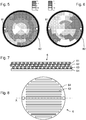
- FIGS. 5 and 6 illustrate the current distribution through an anode 8 associated with an active layer 42 according to the second type, respectively when it is put into service and after a hundred hours of use.
- FIG. 5 illustrates different ranges of current density in A / cm 2 .
- the invention has made it possible to obtain a relatively homogeneous current density for the different zones, namely the median zone, the intermediate band and the peripheral band. It can therefore be assumed that the aging of the different zones of the membrane / electrode assembly will also be homogeneous.
- the invention makes it possible in particular to avoid the concentration of the current in the median zone.
- the invention also makes it possible to increase the current density for the peripheral zone, which makes it possible to take advantage of an area of the active layer 42 forming the major part of its surface but usually being less efficient due to pressure losses. that the flow of fluid undergoes to join it.
- the average current density at commissioning was 0.405 A / cm 2 .
- the electrochemical cell 2 advantageously comprises a flow-diffusing element 6 arranged between the membrane / electrode assembly 4 and the anode 8.
- the figure 7 is a schematic sectional view of a structure for a first example of water diffusion element 6.
- the water diffusion element 6 here comprises a superposition of several grids 61 to 63 and a porous layer 64
- the porous layer 64 is positioned in contact with the layer 42, the grid 61 being placed in contact with the anode 8.
- three grids 61 to 63 have been superimposed.
- the grids 61 to 63 have relatively large meshes , with a width of at least 1 mm.
- Grids 61 to 63 have the role of distributing water in the volume.
- the porous layer 64 may for example have pores with a size of between 10 and 50 ⁇ m, with a porosity of between 30 and 50%.
- the porous layer 64 is intended to allow a fine distribution of the water to the layer 42.
- the porous layer 64 is also intended to evacuate the gases produced, and allow electrical contact as homogeneous as possible. It is also conceivable to superpose several porous layers 64 with different porosities, in order to create a porosity gradient.
- the grids 61 to 63 and the porous layer 64 are electrically conductive.
- the thickness of this water diffusion element 6 may for example be between 1 and 3 mm.
- the figure 8 is a schematic sectional view of another structure for a second example of a water diffusion element 6.
- the water diffusion element 6 is here in the form of a water flow guide.
- the element 6 is formed in one piece.
- the element 6 comprises walls 64 delimiting flow channels 63.
- the flow channels 63 are parallel to the line X, and thus make it possible to guide a flow of fluid from the collector 81 to the collector 82.
- flow channels 63 is for example between 1 and 3 mm.
Landscapes
- Chemical & Material Sciences (AREA)
- Chemical Kinetics & Catalysis (AREA)
- Electrochemistry (AREA)
- Engineering & Computer Science (AREA)
- Materials Engineering (AREA)
- Metallurgy (AREA)
- Organic Chemistry (AREA)
- Inorganic Chemistry (AREA)
- General Chemical & Material Sciences (AREA)
- Electrolytic Production Of Non-Metals, Compounds, Apparatuses Therefor (AREA)
- Electrodes For Compound Or Non-Metal Manufacture (AREA)
Applications Claiming Priority (1)
| Application Number | Priority Date | Filing Date | Title |
|---|---|---|---|
| FR1850509A FR3077076B1 (fr) | 2018-01-23 | 2018-01-23 | Dispositif d'electrolyse de l'eau pour l'homogeneisation de la densite de courant |
Publications (2)
| Publication Number | Publication Date |
|---|---|
| EP3514871A1 true EP3514871A1 (de) | 2019-07-24 |
| EP3514871B1 EP3514871B1 (de) | 2020-08-12 |
Family
ID=62222829
Family Applications (1)
| Application Number | Title | Priority Date | Filing Date |
|---|---|---|---|
| EP19152189.7A Not-in-force EP3514871B1 (de) | 2018-01-23 | 2019-01-16 | Wasserelektrolysevorrichtung zur homogenisierung der strömungsdichte |
Country Status (4)
| Country | Link |
|---|---|
| US (1) | US20190226097A1 (de) |
| EP (1) | EP3514871B1 (de) |
| JP (1) | JP2019151917A (de) |
| FR (1) | FR3077076B1 (de) |
Citations (3)
| Publication number | Priority date | Publication date | Assignee | Title |
|---|---|---|---|---|
| US20080264780A1 (en) * | 2007-04-26 | 2008-10-30 | Chlorine Engineers Corp., Ltd. | Water electrolysis system |
| US7901549B2 (en) * | 2006-12-06 | 2011-03-08 | General Electric Company | Gas evolving electrolysis system |
| US20170044678A1 (en) * | 2012-01-06 | 2017-02-16 | Commissariat A L'energie Atomique Et Aux Energies Alternatives | Porous electrode for proton-exchange membrane |
Family Cites Families (5)
| Publication number | Priority date | Publication date | Assignee | Title |
|---|---|---|---|---|
| FR2945378B1 (fr) * | 2009-05-11 | 2011-10-14 | Commissariat Energie Atomique | Cellule de pile a combustible haute temperature a reformage interne d'hydrocarbures. |
| JP5603928B2 (ja) * | 2010-03-23 | 2014-10-08 | 本田技研工業株式会社 | 電気化学装置 |
| US10273586B2 (en) * | 2014-02-20 | 2019-04-30 | Proton Energy Systems, Inc. | Electrochemical cell |
| TWI618837B (zh) * | 2016-06-17 | 2018-03-21 | Yuan Ze University | 灌溉系統 |
| DE112017005364T5 (de) * | 2016-10-24 | 2019-07-18 | Precision Combustion, Inc. | Regenerativer festoxidstapel |
-
2018
- 2018-01-23 FR FR1850509A patent/FR3077076B1/fr not_active Expired - Fee Related
-
2019
- 2019-01-16 EP EP19152189.7A patent/EP3514871B1/de not_active Not-in-force
- 2019-01-21 JP JP2019007601A patent/JP2019151917A/ja active Pending
- 2019-01-22 US US16/253,840 patent/US20190226097A1/en not_active Abandoned
Patent Citations (3)
| Publication number | Priority date | Publication date | Assignee | Title |
|---|---|---|---|---|
| US7901549B2 (en) * | 2006-12-06 | 2011-03-08 | General Electric Company | Gas evolving electrolysis system |
| US20080264780A1 (en) * | 2007-04-26 | 2008-10-30 | Chlorine Engineers Corp., Ltd. | Water electrolysis system |
| US20170044678A1 (en) * | 2012-01-06 | 2017-02-16 | Commissariat A L'energie Atomique Et Aux Energies Alternatives | Porous electrode for proton-exchange membrane |
Also Published As
| Publication number | Publication date |
|---|---|
| EP3514871B1 (de) | 2020-08-12 |
| US20190226097A1 (en) | 2019-07-25 |
| FR3077076A1 (fr) | 2019-07-26 |
| FR3077076B1 (fr) | 2020-01-17 |
| JP2019151917A (ja) | 2019-09-12 |
Similar Documents
| Publication | Publication Date | Title |
|---|---|---|
| EP3183379B1 (de) | Verfahren für hochtemperaturelektrolyse oder co-elektrolyse, verfahren zur erzeugung von strom mittels einer sofc-brennstoffzelle und zugehörige verbinder, reaktoren und betriebsverfahren | |
| FR2976592A1 (fr) | Assemblage membrane-electrodes pour dispositif d'electrolyse | |
| EP3516721B1 (de) | Wasserelektrolysereaktor (soec) oder brennstoffzelle (sofc) mit erhöhter wasserdampf- oder brennstoffeinsatzrate | |
| EP2676317B1 (de) | Protonenaustauschmembran-brennstoffzelle mit verbesserter leistung | |
| FR2957363A1 (fr) | Architecture d'electrolyseur a haute temperature, a production cible elevee par cellule d'electrolyse et taux de degradation des cellules limite | |
| FR2957359A1 (fr) | Dispositif d'electrolyse de l'eau a haute temperature a fonctionnement ameliore | |
| EP3514875B1 (de) | Anordnung von zellen für die leistungsanpassung von elektrochemischen reaktoren | |
| EP2800825B1 (de) | Poröse elektrode für protonenaustauschmembran | |
| JP2006338938A (ja) | 電解質膜−電極接合体およびその製造方法 | |
| EP2692009A1 (de) | Brennstoffzelle mit protonenaustauschermembran mit erhöhter lebensdauer | |
| EP2692005B1 (de) | Brennstoffzelle mit protonenaustauschermembran mit erhöhter lebensdauer | |
| FR3026231A1 (fr) | Pile a combustible destinee a la detection d’un polluant | |
| FR3016084A1 (fr) | Interconnecteur electrique et fluidique pour electrolyseur eht ou pile a combustible sofc | |
| EP3514871B1 (de) | Wasserelektrolysevorrichtung zur homogenisierung der strömungsdichte | |
| EP3013738A1 (de) | Vorrichtung zur elektrochemischen reinigung und kompression von wasserstoff mit mehreren stufen | |
| EP2867947A1 (de) | Verfahren zur herstellung einer elektroden-/protonenaustauschmembrananordnung | |
| CA3230063C (fr) | Interconnecteur pour empilement de cellules a oxydes solides de type soec/sofc comportant des elements en relief differents | |
| WO2025012385A1 (fr) | Cellule électrochimique à électrode support structurée | |
| FR3164325A1 (fr) | Procédé de fabrication d’un interconnecteur pour dispositifs électrochimiques à oxyde solide | |
| FR2973580A1 (fr) | Pile a combustible a membrane d'echange de protons presentant une duree de vie accrue | |
| FR2997230A1 (fr) | Pile a combustible a membrane echangeuse de protons presentant une duree de vie et des performances accrues | |
| EP2545203A1 (de) | Vorrichtung zur herstellung eines elektro- und fluidverbinders für einen reaktor für hochtemperaturwasserelektrolyse |
Legal Events
| Date | Code | Title | Description |
|---|---|---|---|
| PUAI | Public reference made under article 153(3) epc to a published international application that has entered the european phase |
Free format text: ORIGINAL CODE: 0009012 |
|
| STAA | Information on the status of an ep patent application or granted ep patent |
Free format text: STATUS: REQUEST FOR EXAMINATION WAS MADE |
|
| 17P | Request for examination filed |
Effective date: 20190116 |
|
| AK | Designated contracting states |
Kind code of ref document: A1 Designated state(s): AL AT BE BG CH CY CZ DE DK EE ES FI FR GB GR HR HU IE IS IT LI LT LU LV MC MK MT NL NO PL PT RO RS SE SI SK SM TR |
|
| AX | Request for extension of the european patent |
Extension state: BA ME |
|
| GRAP | Despatch of communication of intention to grant a patent |
Free format text: ORIGINAL CODE: EPIDOSNIGR1 |
|
| STAA | Information on the status of an ep patent application or granted ep patent |
Free format text: STATUS: GRANT OF PATENT IS INTENDED |
|
| RIC1 | Information provided on ipc code assigned before grant |
Ipc: C25B 9/10 20060101ALI20200212BHEP Ipc: C25B 1/10 20060101ALI20200212BHEP Ipc: H01M 4/86 20060101AFI20200212BHEP Ipc: C25B 9/08 20060101ALI20200212BHEP Ipc: H01M 4/88 20060101ALI20200212BHEP Ipc: C25B 11/03 20060101ALI20200212BHEP Ipc: C25B 11/04 20060101ALI20200212BHEP |
|
| INTG | Intention to grant announced |
Effective date: 20200305 |
|
| GRAS | Grant fee paid |
Free format text: ORIGINAL CODE: EPIDOSNIGR3 |
|
| GRAA | (expected) grant |
Free format text: ORIGINAL CODE: 0009210 |
|
| STAA | Information on the status of an ep patent application or granted ep patent |
Free format text: STATUS: THE PATENT HAS BEEN GRANTED |
|
| AK | Designated contracting states |
Kind code of ref document: B1 Designated state(s): AL AT BE BG CH CY CZ DE DK EE ES FI FR GB GR HR HU IE IS IT LI LT LU LV MC MK MT NL NO PL PT RO RS SE SI SK SM TR |
|
| REG | Reference to a national code |
Ref country code: CH Ref legal event code: EP |
|
| REG | Reference to a national code |
Ref country code: IE Ref legal event code: FG4D Free format text: LANGUAGE OF EP DOCUMENT: FRENCH |
|
| REG | Reference to a national code |
Ref country code: DE Ref legal event code: R096 Ref document number: 602019000422 Country of ref document: DE |
|
| REG | Reference to a national code |
Ref country code: AT Ref legal event code: REF Ref document number: 1302437 Country of ref document: AT Kind code of ref document: T Effective date: 20200915 |
|
| REG | Reference to a national code |
Ref country code: LT Ref legal event code: MG4D |
|
| REG | Reference to a national code |
Ref country code: NL Ref legal event code: MP Effective date: 20200812 |
|
| PG25 | Lapsed in a contracting state [announced via postgrant information from national office to epo] |
Ref country code: GR Free format text: LAPSE BECAUSE OF FAILURE TO SUBMIT A TRANSLATION OF THE DESCRIPTION OR TO PAY THE FEE WITHIN THE PRESCRIBED TIME-LIMIT Effective date: 20201113 Ref country code: NO Free format text: LAPSE BECAUSE OF FAILURE TO SUBMIT A TRANSLATION OF THE DESCRIPTION OR TO PAY THE FEE WITHIN THE PRESCRIBED TIME-LIMIT Effective date: 20201112 Ref country code: LT Free format text: LAPSE BECAUSE OF FAILURE TO SUBMIT A TRANSLATION OF THE DESCRIPTION OR TO PAY THE FEE WITHIN THE PRESCRIBED TIME-LIMIT Effective date: 20200812 Ref country code: FI Free format text: LAPSE BECAUSE OF FAILURE TO SUBMIT A TRANSLATION OF THE DESCRIPTION OR TO PAY THE FEE WITHIN THE PRESCRIBED TIME-LIMIT Effective date: 20200812 Ref country code: BG Free format text: LAPSE BECAUSE OF FAILURE TO SUBMIT A TRANSLATION OF THE DESCRIPTION OR TO PAY THE FEE WITHIN THE PRESCRIBED TIME-LIMIT Effective date: 20201112 Ref country code: SE Free format text: LAPSE BECAUSE OF FAILURE TO SUBMIT A TRANSLATION OF THE DESCRIPTION OR TO PAY THE FEE WITHIN THE PRESCRIBED TIME-LIMIT Effective date: 20200812 Ref country code: HR Free format text: LAPSE BECAUSE OF FAILURE TO SUBMIT A TRANSLATION OF THE DESCRIPTION OR TO PAY THE FEE WITHIN THE PRESCRIBED TIME-LIMIT Effective date: 20200812 |
|
| REG | Reference to a national code |
Ref country code: AT Ref legal event code: MK05 Ref document number: 1302437 Country of ref document: AT Kind code of ref document: T Effective date: 20200812 |
|
| PG25 | Lapsed in a contracting state [announced via postgrant information from national office to epo] |
Ref country code: LV Free format text: LAPSE BECAUSE OF FAILURE TO SUBMIT A TRANSLATION OF THE DESCRIPTION OR TO PAY THE FEE WITHIN THE PRESCRIBED TIME-LIMIT Effective date: 20200812 Ref country code: PL Free format text: LAPSE BECAUSE OF FAILURE TO SUBMIT A TRANSLATION OF THE DESCRIPTION OR TO PAY THE FEE WITHIN THE PRESCRIBED TIME-LIMIT Effective date: 20200812 Ref country code: RS Free format text: LAPSE BECAUSE OF FAILURE TO SUBMIT A TRANSLATION OF THE DESCRIPTION OR TO PAY THE FEE WITHIN THE PRESCRIBED TIME-LIMIT Effective date: 20200812 Ref country code: NL Free format text: LAPSE BECAUSE OF FAILURE TO SUBMIT A TRANSLATION OF THE DESCRIPTION OR TO PAY THE FEE WITHIN THE PRESCRIBED TIME-LIMIT Effective date: 20200812 Ref country code: IS Free format text: LAPSE BECAUSE OF FAILURE TO SUBMIT A TRANSLATION OF THE DESCRIPTION OR TO PAY THE FEE WITHIN THE PRESCRIBED TIME-LIMIT Effective date: 20201212 |
|
| PG25 | Lapsed in a contracting state [announced via postgrant information from national office to epo] |
Ref country code: SM Free format text: LAPSE BECAUSE OF FAILURE TO SUBMIT A TRANSLATION OF THE DESCRIPTION OR TO PAY THE FEE WITHIN THE PRESCRIBED TIME-LIMIT Effective date: 20200812 Ref country code: EE Free format text: LAPSE BECAUSE OF FAILURE TO SUBMIT A TRANSLATION OF THE DESCRIPTION OR TO PAY THE FEE WITHIN THE PRESCRIBED TIME-LIMIT Effective date: 20200812 Ref country code: RO Free format text: LAPSE BECAUSE OF FAILURE TO SUBMIT A TRANSLATION OF THE DESCRIPTION OR TO PAY THE FEE WITHIN THE PRESCRIBED TIME-LIMIT Effective date: 20200812 Ref country code: DK Free format text: LAPSE BECAUSE OF FAILURE TO SUBMIT A TRANSLATION OF THE DESCRIPTION OR TO PAY THE FEE WITHIN THE PRESCRIBED TIME-LIMIT Effective date: 20200812 Ref country code: CZ Free format text: LAPSE BECAUSE OF FAILURE TO SUBMIT A TRANSLATION OF THE DESCRIPTION OR TO PAY THE FEE WITHIN THE PRESCRIBED TIME-LIMIT Effective date: 20200812 |
|
| REG | Reference to a national code |
Ref country code: DE Ref legal event code: R097 Ref document number: 602019000422 Country of ref document: DE |
|
| PG25 | Lapsed in a contracting state [announced via postgrant information from national office to epo] |
Ref country code: AL Free format text: LAPSE BECAUSE OF FAILURE TO SUBMIT A TRANSLATION OF THE DESCRIPTION OR TO PAY THE FEE WITHIN THE PRESCRIBED TIME-LIMIT Effective date: 20200812 Ref country code: AT Free format text: LAPSE BECAUSE OF FAILURE TO SUBMIT A TRANSLATION OF THE DESCRIPTION OR TO PAY THE FEE WITHIN THE PRESCRIBED TIME-LIMIT Effective date: 20200812 Ref country code: ES Free format text: LAPSE BECAUSE OF FAILURE TO SUBMIT A TRANSLATION OF THE DESCRIPTION OR TO PAY THE FEE WITHIN THE PRESCRIBED TIME-LIMIT Effective date: 20200812 |
|
| PLBE | No opposition filed within time limit |
Free format text: ORIGINAL CODE: 0009261 |
|
| STAA | Information on the status of an ep patent application or granted ep patent |
Free format text: STATUS: NO OPPOSITION FILED WITHIN TIME LIMIT |
|
| PG25 | Lapsed in a contracting state [announced via postgrant information from national office to epo] |
Ref country code: SK Free format text: LAPSE BECAUSE OF FAILURE TO SUBMIT A TRANSLATION OF THE DESCRIPTION OR TO PAY THE FEE WITHIN THE PRESCRIBED TIME-LIMIT Effective date: 20200812 |
|
| 26N | No opposition filed |
Effective date: 20210514 |
|
| PG25 | Lapsed in a contracting state [announced via postgrant information from national office to epo] |
Ref country code: IT Free format text: LAPSE BECAUSE OF FAILURE TO SUBMIT A TRANSLATION OF THE DESCRIPTION OR TO PAY THE FEE WITHIN THE PRESCRIBED TIME-LIMIT Effective date: 20200812 |
|
| PG25 | Lapsed in a contracting state [announced via postgrant information from national office to epo] |
Ref country code: MC Free format text: LAPSE BECAUSE OF FAILURE TO SUBMIT A TRANSLATION OF THE DESCRIPTION OR TO PAY THE FEE WITHIN THE PRESCRIBED TIME-LIMIT Effective date: 20200812 Ref country code: SI Free format text: LAPSE BECAUSE OF FAILURE TO SUBMIT A TRANSLATION OF THE DESCRIPTION OR TO PAY THE FEE WITHIN THE PRESCRIBED TIME-LIMIT Effective date: 20200812 |
|
| PG25 | Lapsed in a contracting state [announced via postgrant information from national office to epo] |
Ref country code: LU Free format text: LAPSE BECAUSE OF NON-PAYMENT OF DUE FEES Effective date: 20210116 |
|
| REG | Reference to a national code |
Ref country code: BE Ref legal event code: MM Effective date: 20210131 |
|
| PG25 | Lapsed in a contracting state [announced via postgrant information from national office to epo] |
Ref country code: IE Free format text: LAPSE BECAUSE OF NON-PAYMENT OF DUE FEES Effective date: 20210116 |
|
| PG25 | Lapsed in a contracting state [announced via postgrant information from national office to epo] |
Ref country code: BE Free format text: LAPSE BECAUSE OF NON-PAYMENT OF DUE FEES Effective date: 20210131 |
|
| REG | Reference to a national code |
Ref country code: CH Ref legal event code: PL |
|
| PG25 | Lapsed in a contracting state [announced via postgrant information from national office to epo] |
Ref country code: LI Free format text: LAPSE BECAUSE OF NON-PAYMENT OF DUE FEES Effective date: 20220131 Ref country code: CH Free format text: LAPSE BECAUSE OF NON-PAYMENT OF DUE FEES Effective date: 20220131 |
|
| PG25 | Lapsed in a contracting state [announced via postgrant information from national office to epo] |
Ref country code: PT Free format text: LAPSE BECAUSE OF FAILURE TO SUBMIT A TRANSLATION OF THE DESCRIPTION OR TO PAY THE FEE WITHIN THE PRESCRIBED TIME-LIMIT Effective date: 20201214 |
|
| PG25 | Lapsed in a contracting state [announced via postgrant information from national office to epo] |
Ref country code: CY Free format text: LAPSE BECAUSE OF FAILURE TO SUBMIT A TRANSLATION OF THE DESCRIPTION OR TO PAY THE FEE WITHIN THE PRESCRIBED TIME-LIMIT Effective date: 20200812 |
|
| PG25 | Lapsed in a contracting state [announced via postgrant information from national office to epo] |
Ref country code: HU Free format text: LAPSE BECAUSE OF FAILURE TO SUBMIT A TRANSLATION OF THE DESCRIPTION OR TO PAY THE FEE WITHIN THE PRESCRIBED TIME-LIMIT; INVALID AB INITIO Effective date: 20190116 |
|
| GBPC | Gb: european patent ceased through non-payment of renewal fee |
Effective date: 20230116 |
|
| PG25 | Lapsed in a contracting state [announced via postgrant information from national office to epo] |
Ref country code: GB Free format text: LAPSE BECAUSE OF NON-PAYMENT OF DUE FEES Effective date: 20230116 |
|
| PG25 | Lapsed in a contracting state [announced via postgrant information from national office to epo] |
Ref country code: MK Free format text: LAPSE BECAUSE OF FAILURE TO SUBMIT A TRANSLATION OF THE DESCRIPTION OR TO PAY THE FEE WITHIN THE PRESCRIBED TIME-LIMIT Effective date: 20200812 |
|
| PGFP | Annual fee paid to national office [announced via postgrant information from national office to epo] |
Ref country code: DE Payment date: 20240119 Year of fee payment: 6 |
|
| PGFP | Annual fee paid to national office [announced via postgrant information from national office to epo] |
Ref country code: FR Payment date: 20240118 Year of fee payment: 6 |
|
| PG25 | Lapsed in a contracting state [announced via postgrant information from national office to epo] |
Ref country code: TR Free format text: LAPSE BECAUSE OF FAILURE TO SUBMIT A TRANSLATION OF THE DESCRIPTION OR TO PAY THE FEE WITHIN THE PRESCRIBED TIME-LIMIT Effective date: 20200812 |
|
| PG25 | Lapsed in a contracting state [announced via postgrant information from national office to epo] |
Ref country code: MT Free format text: LAPSE BECAUSE OF FAILURE TO SUBMIT A TRANSLATION OF THE DESCRIPTION OR TO PAY THE FEE WITHIN THE PRESCRIBED TIME-LIMIT Effective date: 20200812 |
|
| REG | Reference to a national code |
Ref country code: DE Ref legal event code: R119 Ref document number: 602019000422 Country of ref document: DE |
|
| PG25 | Lapsed in a contracting state [announced via postgrant information from national office to epo] |
Ref country code: DE Free format text: LAPSE BECAUSE OF NON-PAYMENT OF DUE FEES Effective date: 20250801 |
|
| PG25 | Lapsed in a contracting state [announced via postgrant information from national office to epo] |
Ref country code: FR Free format text: LAPSE BECAUSE OF NON-PAYMENT OF DUE FEES Effective date: 20250131 |