EP3514766A2 - Elektronische vorrichtung, verfahren zur anzeige einer szene mit erweiterter realität und nichttransitorisches computerlesbares medium - Google Patents
Elektronische vorrichtung, verfahren zur anzeige einer szene mit erweiterter realität und nichttransitorisches computerlesbares medium Download PDFInfo
- Publication number
- EP3514766A2 EP3514766A2 EP19152771.2A EP19152771A EP3514766A2 EP 3514766 A2 EP3514766 A2 EP 3514766A2 EP 19152771 A EP19152771 A EP 19152771A EP 3514766 A2 EP3514766 A2 EP 3514766A2
- Authority
- EP
- European Patent Office
- Prior art keywords
- image
- environment
- virtual object
- processor
- images
- Prior art date
- Legal status (The legal status is an assumption and is not a legal conclusion. Google has not performed a legal analysis and makes no representation as to the accuracy of the status listed.)
- Withdrawn
Links
Images






Classifications
-
- G—PHYSICS
- G06—COMPUTING OR CALCULATING; COUNTING
- G06T—IMAGE DATA PROCESSING OR GENERATION, IN GENERAL
- G06T15/00—Three-dimensional [3D] image rendering
- G06T15/50—Lighting effects
- G06T15/506—Illumination models
-
- G—PHYSICS
- G06—COMPUTING OR CALCULATING; COUNTING
- G06T—IMAGE DATA PROCESSING OR GENERATION, IN GENERAL
- G06T15/00—Three-dimensional [3D] image rendering
- G06T15/10—Geometric effects
- G06T15/20—Perspective computation
- G06T15/205—Image-based rendering
-
- G—PHYSICS
- G06—COMPUTING OR CALCULATING; COUNTING
- G06T—IMAGE DATA PROCESSING OR GENERATION, IN GENERAL
- G06T15/00—Three-dimensional [3D] image rendering
- G06T15/50—Lighting effects
- G06T15/60—Shadow generation
-
- G—PHYSICS
- G06—COMPUTING OR CALCULATING; COUNTING
- G06T—IMAGE DATA PROCESSING OR GENERATION, IN GENERAL
- G06T19/00—Manipulating three-dimensional [3D] models or images for computer graphics
- G06T19/006—Mixed reality
-
- G—PHYSICS
- G06—COMPUTING OR CALCULATING; COUNTING
- G06T—IMAGE DATA PROCESSING OR GENERATION, IN GENERAL
- G06T3/00—Geometric image transformations in the plane of the image
- G06T3/40—Scaling of whole images or parts thereof, e.g. expanding or contracting
- G06T3/4038—Image mosaicing, e.g. composing plane images from plane sub-images
-
- G—PHYSICS
- G06—COMPUTING OR CALCULATING; COUNTING
- G06T—IMAGE DATA PROCESSING OR GENERATION, IN GENERAL
- G06T2215/00—Indexing scheme for image rendering
- G06T2215/12—Shadow map, environment map
-
- G—PHYSICS
- G06—COMPUTING OR CALCULATING; COUNTING
- G06T—IMAGE DATA PROCESSING OR GENERATION, IN GENERAL
- G06T2215/00—Indexing scheme for image rendering
- G06T2215/16—Using real world measurements to influence rendering
Definitions
- the present application relates to an electronic device and method for displaying an augmented reality scene and non-transitory computer-readable medium. More particularly, the present application relates to an electronic device and method for displaying a virtual object in the augmented reality scene and non-transitory computer-readable medium.
- the virtual object In the augmented reality (AR) system or the mixed reality (MR) system, if the virtual object is blended into the real world environment, it is need to make the lighting configuration of the virtual object and the lighting of real-world environment as similar as possible. Because of the performance issue, existing real-time environment lighting techniques usually do not simulate shadows. However, the shadows of the virtual object can provide depth information to viewers and greatly improve rendering quality. Therefore, an electronic device for capturing the lighting configuration of real-world environment into the mixed reality or the augmented reality system is required.
- AR augmented reality
- MR mixed reality
- An aspect of the disclosure is to provide an electronic device located in a physical environment.
- the electronic device includes a camera unit, a displayer and a processor.
- the camera unit is configured to capture a plurality of images of the physical environment.
- the displayer is configured to display an AR image, wherein content of the AR image comprises a virtual object and object corresponding to the physical environment.
- the processor is electrically connected to the camera unit and the displayer.
- the processor is configured to stitch the plurality of images to generate an environment image; calculate an environment light and a reflection of the physical environment corresponding to the virtual object according to the environment image; analyze direction of a lighting to calculate a shadow corresponding to the virtual object according to the environment image; and render the virtual object on the AR image according to the environment light, the reflection, and the shadow.
- Another aspect of the disclosure is to provide a method for displaying an augmented reality scene.
- the method includes operations of: capturing a plurality of images of the physical environment by a camera unit; stitching the plurality of images to generate an environment image by a processor; calculating an environment light and a reflection of the physical environment corresponding to a virtual object according to the environment image by the processor; analyzing direction of a lighting to calculate a shadow corresponding to the virtual object according to the environment image by the processor; rendering the virtual object on an AR image according to the environment light, the reflection, and the shadow by the processor; and displaying the AR image by a displayer, wherein content of the AR image comprises the virtual object and object corresponding to the physical environment.
- Another aspect of the disclosure is to provide a non-transitory computer-readable medium including one or more sequences of instructions to be executed by a processor of an electronic device for performing a method for displaying an augmented reality scene, wherein the method includes operations of: capturing a plurality of images of the physical environment by a camera unit; stitching the plurality of images to generate an environment image by a processor; calculating an environment light and a reflection of the physical environment corresponding to a virtual object according to the environment image by the processor; analyzing direction of a lighting to calculate a shadow corresponding to the virtual object according to the environment image by the processor; rendering the virtual object on an AR image according to the environment light, the reflection, and the shadow by the processor; and displaying the AR image by a displayer, wherein content of the AR image comprises the virtual object and object corresponding to the physical environment.
- FIG. 1 is a functional block diagram illustrating an electronic device 100 according to an embodiment of the disclosure.
- the electronic device 100 includes a camera unit 110, a processor 130 and a displayer 150.
- the processor 130 is electrically connected to the camera unit 110 and the displayer 150.
- the electronic device 100 can be a device of an augmented reality (AR) system or a mixed reality (MR) system, such as a head-mounted display (HMD).
- the processor 130 can be implemented by a central processing unit, a control circuit and/or a graphics processing unit.
- the displayer 150 will cover visions of the user, and the displayer 150 is configured for displaying a mixed reality scene or an augmented reality scene to the user.
- the processor 130 is coupled to the displayer 150.
- the processor 130 is configured to process image/video data of the AR (or MR) scene to be displayed on the displayer 150.
- the AR/MR scene may include virtual objects (e.g. teapot, statue, glass, etc.) and/or the physical environment features (e.g. walls, doors, tables, windows, etc.).
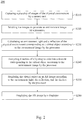
- FIG. 2 is a flow diagram illustrating a method 200 according to an embodiment of this disclosure.
- the method 200 for displaying an augmented reality scene can be utilized to perform computations for rendering the virtual object and to combine the virtual objects and the physical environment features together to form AR images.
- the content of AR images has the virtual object and the object corresponding to the physical environment.
- the AR scene is formed by a plurality of AR images.
- the method 200 firstly executes step S210 to capture a plurality of images of the physical environment by a camera unit 110.
- FIG. 3A is a schematic diagram illustrating an AR scene SCN according to an embodiment of this disclosure.
- the AR scene SCN can include image data Img with a sphere shaped AR scenario surrounding the user wearing the electronic device 100. The disclosed is not limited to the sphere shaped AR scenario.
- the AR scene SCN can include image data Img with a hemisphere shaped AR scenario, a circular ring shaped AR scenario or other equivalent shapes.
- the method 200 executes step S220 to stitch the images to generate an environment image by a processor 130.
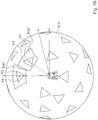
- FIG. 3B is a schematic diagram illustrating the matching target MT and the initial view point VP according to an embodiment of this disclosure.
- the environment image can be realized to a skybox of the physical environment.
- the camera unit 110 of the electronic device 100 is configured to capture an image Img1 of the AR scene SCN. It is noticed that each image captured from the camera unit 110 includes a position data of the camera unit 110.
- the view point VP is moved and rotated along with the electronic device 100, and the plurality of matching targets MT are around of the view point VP.
- the camera unit 110 is configured to captured an initial image Img1, and the coordinate of the initial position of the camera unit 110 is Ip(0, 0, 0).
- an assisting target can be utilized to help the user to align the matching target MT.
- the assisting target can be implemented as the same shape of the matching target MT or different shape of the matching target MT.
- the number of the matching target MT can be set to be larger than 12. The shape and the number of assisting target should not be limited thereto.
- FIG. 3C is a schematic diagram illustrating the environment image EI according to an embodiment of this disclosure.
- the processor 130 is configured to stitch the initial image Img1 into the environment image EI.
- the view point VP' is moved and rotated to a new position and matched another matching target MT, the camera unit 110 is configured to capture another image Img2.
- the processor 130 is further configured to calculate a quality of current image Img2 according to a distance between a current position and an initial position.
- the current position is corresponding to the position of the camera unit 110 captured the image Img2.
- the quality of current image Img2 could be calculated by Formula 1.
- the coordinate of the initial position of the camera unit 110 is Ip(0, 0, 0) and the coordinate of the current position of the camera unit 110 is Cp(10, 10, 10). Therefore, the quality of current image Img2 can be obtained by the Formula 1. If the distance between the current position and the initial position is farther, the quality of current image Img2 would be worse, and thus the distance has an inverse relation with the quality.
- Qp Distance Cp Ip ⁇ 1
- FIG. 3D is a schematic diagram illustrating the environment image EI according to an embodiment of this disclosure.
- the processor 130 is configured to stitch the current image Img2 into the environment image EI.
- the initial image Img1 and the current image Img2 is overlapped in the region R.
- the processor 130 is configured to compare the quality of the initial image Img1 and the quality of the current image Img2. In an embodiment, the image with lower quality will be ignored, the overlapped region R will be updated to the image with better quality. In this case, quality of the initial image Img1 is better than quality of the current image Img2. Therefore, the overlapped region R will be updated to data of the initial image Img1.
- the image with lower quality will be blended with the image with better quality.
- the overlapped region R will be updated to data of the initial image Img1 blended with the current image Img2.
- the ratio of blending can be adjusted. For example, if the initial image Img1 has the better quality, the ratio of blending of the initial image Img1 can be set as 0.8, and the ratio of blending of the current image Img2 can be set as 0.2.
- the disclosure is not limited thereto.
- the view point VP when the view point VP is matched all of the matching target MT, it is can realize that the environment image EI is generated. It is noticed that, the images captured by the camera unit 110 is corresponding to the physical environment, and thus the environment image EI is a skybox corresponding to the physical environment.
- FIG. 4 is a schematic diagram illustrating views of the electronic device 100 in the physical environment PE according to an embodiment of this disclosure.
- the camera unit 110 of the electronic device 100 is configured to capture a plurality of images of the physical environment PE.
- the objects PO1, PO2 and PO3 have different texture.
- FIG. 5A is a schematic diagram illustrating the virtual object VO according to an embodiment of this disclosure.
- the processor 130 when the processor 130 is configured to render the virtual object VO into the physical environment PE, the user can see the virtual object VO in the AR scene SCN via the electronic device 100. It is assumed that the virtual object VO is a bottle with metal material.
- the texture of the virtual object VO is a default texture (i.e. net texture).
- the object PO1 has the shadow S1 and the object PO2 has the shadow S2, due to lighting from the lamp L.
- the virtual object VO with the default texture is unmatched with surrounding objects in the physical environment PE, the virtual object VO rendered by the processor 130 may be seen unrealistic in the physical environment PE.
- the method 200 executes step S230 to calculate an environment light and a reflection of the physical environment PE corresponding to a virtual object VO according to the environment image EI by the processor 130.
- the processor 130 is configured to utilize a spherical harmonics (SH) function to calculate the environment light corresponding to the virtual object VO according to the environment image EI.
- SH spherical harmonics
- the graphics engine e.g. Unity 3D, Unreal Engine, etc
- SH spherical harmonics
- SH spherical harmonics
- the processor 130 is configured to generate a cube map according to the environment image EI, and to calculate the reflection corresponding to the virtual object VO according to the cube map.
- cube maps generally include six texture map surfaces, each cube face can be represented as some environmental detail, such as illuminated color or texture. Therefore, the cube map may be used to impart realistic environmental lighting effects on the virtual object being rendered, giving the virtual object a realistic look and feel within the context of the scene.
- FIG. 5B is a schematic diagram illustrating the virtual object VO is rendered in the physical environment PE according to an embodiment of this disclosure.
- the environment light and the reflection of the physical environment PE corresponding to the virtual object VO can be calculated according to the environment image EI.
- the texture of the object PO1 is a plus texture (i.e. "+”) with red color
- the texture of the object PO2 is a slash texture (i.e. "/”) with brown color
- the texture of the object PO3 is a dot texture (i.e. " ⁇ ") with blue color
- the texture of the virtual object VO is the default texture (i.e. net texture) with gray color.
- the reflection from the object PO1 to the virtual object VO is calculated and is shown, for example, in an area A1 on the virtual object VO (i.e., plus texture shown within the area A1).
- the reflection from the object PO2 to the virtual object VO is calculated and is shown in, for example, an area A2 on the virtual object VO (i.e., slash texture shown within the area A2).
- the reflection from the object PO3 to the virtual object VO is calculated and is shown, for example, in an area A3 on the virtual object VO (i.e., dot texture shown within the area A3).
- the appearance of the virtual object VO is now displayed as a rendered of textures (slash texture, plus texture, and dot texture) with colors from other objects in the physical environment PE.
- the texture of the virtual object VO is the default texture with gray color.
- the surface (or appearance) of the virtual object VO is now blended with its own net texture and the reflections from textures of other objects PO1 ⁇ PO3.
- the areas A1 ⁇ A4 are just shown for easily illustrating.
- the colors of objects PO1-PO3 and the original color of the virtual object VO are mixed to render on the surface of the virtual object VO.
- the environment image EI can be utilized to generate the environment light and the reflection corresponding to the virtual object VO, and thus the virtual object VO generated after the step S230 can be more realistic than the virtual object VO shown in FIG. 5A .
- step S240 executes step S240 to analyze direction of a lighting to calculate a shadow corresponding to the virtual object VO according to the environment image EI by the processor 130.
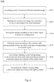
- the step S240 further includes steps S241 ⁇ S246, reference is made to FIG. 6 , which is a flow diagram illustrating step S240 according to an embodiment of this disclosure.
- the method 200 executes step S241 to calculate a total luminance of the environment image EI.
- the processor 130 is configured to calculate the summation of the gray value of the environment image EI.
- the total luminance of the environment image EI is 20000.
- the method 200 executes step S242 to split the environment image EI into a plurality of regions according to the total luminance.
- FIG. 7A is a schematic diagram illustrating the regions of the environment image EI according to an embodiment of this disclosure.
- the processor 130 is configured to split environment image EI into regions R1 and R2 by the splitting line SL1.
- the luminance of region R1 is equal to the luminance of region R2, and it means that the luminance of regions R1 and R2 are both 10000.
- FIG. 7B is a schematic diagram illustrating the regions of the environment image EI according to an embodiment of this disclosure.
- the processor 130 is further configured to split regions R1 into regions R3 and R4 by the splitting line SL2, and to split regions R2 into regions R5 and R6 by the splitting line SL3.
- the luminance of region R3 is equal to the luminance of region R4, and it means that the luminance of regions R3 and R4 are both 5000.
- the luminance of region R5 is equal to the luminance of region R6, and it means that the luminance of regions R5 and R6 are both 5000.
- the times of executions of the step S242 are setting by the number of splitting line or the luminance of region. If the number of executions of the step S242 is increasing, the summation of the luminance of region will be decreasing and the number of region is increasing.
- step S243 to sort the regions according to size of each region to generate a sorting result.
- each regions has similar luminance (i.e. 5000). If the size of region is smaller, the region will be lighting candidates. Therefore, it can be realized that the sorting result is arranged according to the size of the regions (from the largest size to the smallest size). In another embodiment, the sorting result can be arranged from the smallest size to the largest size.
- the disclosure is not limited thereto.
- the method 200 executes step S244 to select region according to the sorting result, and to generate at least one directional light corresponding to selected region.
- the processor 130 if the processor 130 is configured to select the region with the smallest size, the selected region will be a light source and generate a directional light.
- the processor 130 can select multiple of the region in sequence according to the sorting result, or the number of selected region can be set by user.
- the means of selected region should not be limited thereto.
- step S245 to calculate a lighting vector corresponding to the at least one directional light according to position of selected region and position of the virtual object VO.
- FIG. 8 is a schematic diagram illustrating the lighting vector in the physical environment PE according to an embodiment of this disclosure.
- the selected region is a partial of the environment image EI
- position of the selected region in the environment image EI can be obtained.
- the selected region is the region of the lamp L.
- the position of the lamp L in the sphere shaped AR scene SCN can be obtained (the coordinate of the z-axis can be obtained by a default value, multi-view sensor or depth sensor).
- the position of the virtual object VO in the sphere shaped AR scene SCN can be obtained.
- the coordinate of the lamp L are (x1, y1, z1) and the coordinate of the virtual object VO are (x2, y2, z2). Therefore, the lighting vector can be calculated by the coordinate of the lamp L and coordinate of the virtual object VO.
- step S246 to generate the shadow S3 corresponding to the virtual object VO according to the lighting vector.
- FIG. 9 is a schematic diagram illustrating the virtual object VO is rendered in the physical environment PE according to an embodiment of this disclosure.
- the processor 130 is configured to generate the shadow S3 of the virtual object VO according to the lighting vector. Therefore, the virtual object VO has the shadow S3, due to lighting from the lamp L.
- the method 200 executes step S250 to render the virtual object VO on an AR image according to the environment light, the reflection, and the shadow by the processor 130.
- the virtual object VO generated after the step S240 can be more realistic than the virtual object VO shown in FIG. 5B .
- the method 200 further executes step S260 to display the AR image by the displayer 150.
- the displayer 150 is configured to display the AR scene SCN.
- the virtual object VO rendered by the processor 130 in the physical environment PE according to the environment light, the reflection, and the shadow the virtual object VO can be more consistent to the real-world object (e.g. objects PO1, PO2 and PO3).
- the non-transitory computer readable storage medium stores instructions for performing the method 200 for displaying an augmented reality scene in aforesaid embodiment shown in Fig. 2 .
- electronic device, method, and non-transitory computer-readable medium for displaying an augmented reality scene are capable of generating a environment image of the physical environment; calculating the environment light, the reflection, and the shadow according to the environment image; and rendering the virtual object on the AR scene according to the environment light, the reflection, and the shadow.
- the head-mounted display is able to display the virtual object in the augmented reality scenario.
Landscapes
- Engineering & Computer Science (AREA)
- Physics & Mathematics (AREA)
- Theoretical Computer Science (AREA)
- General Physics & Mathematics (AREA)
- Computer Graphics (AREA)
- Computer Hardware Design (AREA)
- General Engineering & Computer Science (AREA)
- Software Systems (AREA)
- Computing Systems (AREA)
- Geometry (AREA)
- Processing Or Creating Images (AREA)
- Image Generation (AREA)
Applications Claiming Priority (1)
| Application Number | Priority Date | Filing Date | Title |
|---|---|---|---|
| US201862619130P | 2018-01-19 | 2018-01-19 |
Publications (2)
| Publication Number | Publication Date |
|---|---|
| EP3514766A2 true EP3514766A2 (de) | 2019-07-24 |
| EP3514766A3 EP3514766A3 (de) | 2019-08-14 |
Family
ID=65138884
Family Applications (1)
| Application Number | Title | Priority Date | Filing Date |
|---|---|---|---|
| EP19152771.2A Withdrawn EP3514766A3 (de) | 2018-01-19 | 2019-01-21 | Elektronische vorrichtung, verfahren zur anzeige einer szene mit erweiterter realität und nichttransitorisches computerlesbares medium |
Country Status (4)
| Country | Link |
|---|---|
| US (1) | US10636200B2 (de) |
| EP (1) | EP3514766A3 (de) |
| CN (1) | CN110070621B (de) |
| TW (1) | TWI711966B (de) |
Cited By (1)
| Publication number | Priority date | Publication date | Assignee | Title |
|---|---|---|---|---|
| CN112562051A (zh) * | 2020-11-30 | 2021-03-26 | 腾讯科技(深圳)有限公司 | 虚拟对象显示方法、装置、设备及存储介质 |
Families Citing this family (19)
| Publication number | Priority date | Publication date | Assignee | Title |
|---|---|---|---|---|
| US20210134049A1 (en) * | 2017-08-08 | 2021-05-06 | Sony Corporation | Image processing apparatus and method |
| US10607567B1 (en) | 2018-03-16 | 2020-03-31 | Amazon Technologies, Inc. | Color variant environment mapping for augmented reality |
| US10777010B1 (en) | 2018-03-16 | 2020-09-15 | Amazon Technologies, Inc. | Dynamic environment mapping for augmented reality |
| US10559121B1 (en) * | 2018-03-16 | 2020-02-11 | Amazon Technologies, Inc. | Infrared reflectivity determinations for augmented reality rendering |
| US10930049B2 (en) * | 2018-08-27 | 2021-02-23 | Apple Inc. | Rendering virtual objects with realistic surface properties that match the environment |
| US11620794B2 (en) * | 2018-12-14 | 2023-04-04 | Intel Corporation | Determining visually reflective properties of physical surfaces in a mixed reality environment |
| TWI767179B (zh) * | 2019-01-24 | 2022-06-11 | 宏達國際電子股份有限公司 | 混合實境中偵測真實世界光源的方法、混合實境系統及記錄媒體 |
| US12175010B2 (en) * | 2019-09-28 | 2024-12-24 | Apple Inc. | Devices, methods, and graphical user interfaces for interacting with three-dimensional environments |
| CN111199573B (zh) * | 2019-12-30 | 2023-07-07 | 成都索贝数码科技股份有限公司 | 一种基于增强现实的虚实互反射方法、装置、介质及设备 |
| CN111639613B (zh) * | 2020-06-04 | 2024-04-16 | 上海商汤智能科技有限公司 | 一种增强现实ar特效生成方法、装置及电子设备 |
| EP3937138A1 (de) * | 2020-07-10 | 2022-01-12 | X-Rite Europe GmbH | Anzeigen eines virtuellen objekts in einer szene des realen lebens |
| CN113313808B (zh) * | 2020-08-27 | 2024-11-29 | 阿里巴巴(深圳)技术有限公司 | 图像处理方法及系统、图像处理设备 |
| CN114979457B (zh) * | 2021-02-26 | 2023-04-07 | 华为技术有限公司 | 一种图像处理方法及相关装置 |
| JP7809720B2 (ja) * | 2021-04-07 | 2026-02-02 | インターディジタル・シーイー・パテント・ホールディングス・ソシエテ・パ・アクシオンス・シンプリフィエ | 光効果をサポートする容積ビデオ |
| CN113393516B (zh) * | 2021-06-17 | 2022-05-24 | 贝壳找房(北京)科技有限公司 | 用于打散ar场景中的虚拟物体的方法和装置 |
| CN115546375A (zh) * | 2021-06-30 | 2022-12-30 | 阿里巴巴新加坡控股有限公司 | 一种增强现实画面的渲染方法、程序产品及存储介质 |
| JP2023111647A (ja) * | 2022-01-31 | 2023-08-10 | 富士フイルムビジネスイノベーション株式会社 | 情報処理装置及び情報処理プログラム |
| US12461640B2 (en) | 2022-09-21 | 2025-11-04 | Apple Inc. | Devices, methods, and graphical user interfaces for displaying shadow and light effects in three-dimensional environments |
| US20250086902A1 (en) * | 2023-09-08 | 2025-03-13 | Htc Corporation | Method for rendering virtual object, host, and computer readable storage medium |
Family Cites Families (11)
| Publication number | Priority date | Publication date | Assignee | Title |
|---|---|---|---|---|
| US8139059B2 (en) * | 2006-03-31 | 2012-03-20 | Microsoft Corporation | Object illumination in a virtual environment |
| US20090046099A1 (en) * | 2006-11-13 | 2009-02-19 | Bunkspeed | Real-time display system |
| EP2072947B1 (de) * | 2007-08-07 | 2016-03-16 | Panasonic Intellectual Property Management Co., Ltd. | Bildverarbeitungsvorrichtung und bildverarbeitungsverfahren |
| US9524585B2 (en) * | 2012-11-05 | 2016-12-20 | Microsoft Technology Licensing, Llc | Constructing augmented reality environment with pre-computed lighting |
| US20140240354A1 (en) * | 2013-02-28 | 2014-08-28 | Samsung Electronics Co., Ltd. | Augmented reality apparatus and method |
| US10262462B2 (en) * | 2014-04-18 | 2019-04-16 | Magic Leap, Inc. | Systems and methods for augmented and virtual reality |
| CN104102412B (zh) * | 2014-07-24 | 2017-12-12 | 央数文化(上海)股份有限公司 | 一种基于增强现实技术的手持式阅览设备及其方法 |
| CN104766270B (zh) * | 2015-03-20 | 2017-10-03 | 北京理工大学 | 一种基于鱼眼镜头的虚实光照融合方法 |
| US9355433B1 (en) * | 2015-06-30 | 2016-05-31 | Gopro, Inc. | Image stitching in a multi-camera array |
| KR102716991B1 (ko) * | 2017-02-28 | 2024-10-15 | 삼성전자주식회사 | 외부 전자 장치를 이용한 촬영 방법 및 이를 지원하는 전자 장치 |
| CN107093204A (zh) * | 2017-04-14 | 2017-08-25 | 苏州蜗牛数字科技股份有限公司 | 一种基于全景画面影响虚拟对象光影效果的方法 |
-
2019
- 2019-01-18 CN CN201910049440.9A patent/CN110070621B/zh active Active
- 2019-01-18 TW TW108102067A patent/TWI711966B/zh active
- 2019-01-18 US US16/251,088 patent/US10636200B2/en active Active
- 2019-01-21 EP EP19152771.2A patent/EP3514766A3/de not_active Withdrawn
Non-Patent Citations (1)
| Title |
|---|
| None |
Cited By (2)
| Publication number | Priority date | Publication date | Assignee | Title |
|---|---|---|---|---|
| CN112562051A (zh) * | 2020-11-30 | 2021-03-26 | 腾讯科技(深圳)有限公司 | 虚拟对象显示方法、装置、设备及存储介质 |
| CN112562051B (zh) * | 2020-11-30 | 2023-06-27 | 腾讯科技(深圳)有限公司 | 虚拟对象显示方法、装置、设备及存储介质 |
Also Published As
| Publication number | Publication date |
|---|---|
| TW201933084A (zh) | 2019-08-16 |
| US20190228568A1 (en) | 2019-07-25 |
| CN110070621A (zh) | 2019-07-30 |
| TWI711966B (zh) | 2020-12-01 |
| EP3514766A3 (de) | 2019-08-14 |
| CN110070621B (zh) | 2023-04-07 |
| US10636200B2 (en) | 2020-04-28 |
Similar Documents
| Publication | Publication Date | Title |
|---|---|---|
| EP3514766A2 (de) | Elektronische vorrichtung, verfahren zur anzeige einer szene mit erweiterter realität und nichttransitorisches computerlesbares medium | |
| US20190206119A1 (en) | Mixed reality display device | |
| Kalkofen et al. | Visualization techniques for augmented reality | |
| CN106648049B (zh) | 一种基于眼球追踪及眼动点预测的立体渲染方法 | |
| US6876362B1 (en) | Omnidirectional shadow texture mapping | |
| US20090128552A1 (en) | Image processing apparatus for combining real object and virtual object and processing method therefor | |
| GB2465792A (en) | Illumination Direction Estimation using Reference Object | |
| JP3759971B2 (ja) | 3次元像を陰影付けする方法 | |
| JP2023087027A (ja) | 情報処理装置、情報処理方法及びプログラム | |
| JP2023514796A (ja) | 物理物体による拡張現実内の仮想物体のオクルージョン | |
| WO2015090421A1 (en) | Method and system for providing information associated with a view of a real environment superimposed with a virtual object | |
| CN114663632B (zh) | 基于空间位置的光照显示虚拟物体的方法及设备 | |
| CN116030228B (zh) | 一种基于web的mr虚拟画面展示方法及装置 | |
| US20180286130A1 (en) | Graphical image augmentation of physical objects | |
| CN106780297A (zh) | 场景和光照变化条件下的图像高精度配准方法 | |
| US10719124B2 (en) | Tracking system, tracking method for real-time rendering an image and non-transitory computer-readable medium | |
| US8464170B2 (en) | 2D editing metaphor for 3D graphics | |
| CN107464278A (zh) | 全视向的球体光场渲染方法 | |
| JP2024523729A (ja) | 3d環境におけるリアルタイム光線追跡のためのシステム及び方法 | |
| Schwandt et al. | Glossy reflections for mixed reality environments on mobile devices | |
| Chen et al. | Rapid creation of photorealistic virtual reality content with consumer depth cameras | |
| JP6898264B2 (ja) | 合成装置、方法及びプログラム | |
| CN115063307B (zh) | 一种基于亮度一致性的增强现实色度调节方法 | |
| CN107422952B (zh) | 一种立体图形显示的方法、装置及设备 | |
| CN117372502A (zh) | 针对目标易损性分析的群目标投影面积计算方法及系统 |
Legal Events
| Date | Code | Title | Description |
|---|---|---|---|
| PUAI | Public reference made under article 153(3) epc to a published international application that has entered the european phase |
Free format text: ORIGINAL CODE: 0009012 |
|
| PUAL | Search report despatched |
Free format text: ORIGINAL CODE: 0009013 |
|
| 17P | Request for examination filed |
Effective date: 20190121 |
|
| AK | Designated contracting states |
Kind code of ref document: A2 Designated state(s): AL AT BE BG CH CY CZ DE DK EE ES FI FR GB GR HR HU IE IS IT LI LT LU LV MC MK MT NL NO PL PT RO RS SE SI SK SM TR |
|
| AX | Request for extension of the european patent |
Extension state: BA ME |
|
| AK | Designated contracting states |
Kind code of ref document: A3 Designated state(s): AL AT BE BG CH CY CZ DE DK EE ES FI FR GB GR HR HU IE IS IT LI LT LU LV MC MK MT NL NO PL PT RO RS SE SI SK SM TR |
|
| AX | Request for extension of the european patent |
Extension state: BA ME |
|
| RIC1 | Information provided on ipc code assigned before grant |
Ipc: G06T 15/50 20110101ALI20190710BHEP Ipc: G06T 19/00 20110101AFI20190710BHEP Ipc: G06T 15/60 20060101ALI20190710BHEP Ipc: G06T 3/40 20060101ALI20190710BHEP |
|
| 17Q | First examination report despatched |
Effective date: 20190726 |
|
| RBV | Designated contracting states (corrected) |
Designated state(s): AL AT BE BG CH CY CZ DE DK EE ES FI FR GB GR HR HU IE IS IT LI LT LU LV MC MK MT NL NO PL PT RO RS SE SI SK SM TR |
|
| STAA | Information on the status of an ep patent application or granted ep patent |
Free format text: STATUS: THE APPLICATION IS DEEMED TO BE WITHDRAWN |
|
| 18D | Application deemed to be withdrawn |
Effective date: 20200306 |