EP3514459B1 - Air conditioner - Google Patents
Air conditioner Download PDFInfo
- Publication number
- EP3514459B1 EP3514459B1 EP17862937.4A EP17862937A EP3514459B1 EP 3514459 B1 EP3514459 B1 EP 3514459B1 EP 17862937 A EP17862937 A EP 17862937A EP 3514459 B1 EP3514459 B1 EP 3514459B1
- Authority
- EP
- European Patent Office
- Prior art keywords
- air
- door
- fan
- air outlet
- air conditioner
- Prior art date
- Legal status (The legal status is an assumption and is not a legal conclusion. Google has not performed a legal analysis and makes no representation as to the accuracy of the status listed.)
- Active
Links
- 239000003507 refrigerant Substances 0.000 description 11
- 238000001816 cooling Methods 0.000 description 5
- 238000005057 refrigeration Methods 0.000 description 4
- XLYOFNOQVPJJNP-UHFFFAOYSA-N water Substances O XLYOFNOQVPJJNP-UHFFFAOYSA-N 0.000 description 4
- 230000001143 conditioned effect Effects 0.000 description 3
- 238000007599 discharging Methods 0.000 description 3
- 238000006073 displacement reaction Methods 0.000 description 3
- 239000000428 dust Substances 0.000 description 3
- 230000000694 effects Effects 0.000 description 3
- 239000007788 liquid Substances 0.000 description 3
- 238000000034 method Methods 0.000 description 3
- 238000007664 blowing Methods 0.000 description 2
- 238000010438 heat treatment Methods 0.000 description 2
- 230000005855 radiation Effects 0.000 description 2
- 239000000126 substance Substances 0.000 description 2
- 230000006835 compression Effects 0.000 description 1
- 238000007906 compression Methods 0.000 description 1
- 230000003750 conditioning effect Effects 0.000 description 1
- 238000001704 evaporation Methods 0.000 description 1
- 230000008020 evaporation Effects 0.000 description 1
- 238000009434 installation Methods 0.000 description 1
- 238000012986 modification Methods 0.000 description 1
- 230000004048 modification Effects 0.000 description 1
- 239000002245 particle Substances 0.000 description 1
- 239000003381 stabilizer Substances 0.000 description 1
- 238000009834 vaporization Methods 0.000 description 1
- 230000008016 vaporization Effects 0.000 description 1
Images


Classifications
-
- F—MECHANICAL ENGINEERING; LIGHTING; HEATING; WEAPONS; BLASTING
- F24—HEATING; RANGES; VENTILATING
- F24F—AIR-CONDITIONING; AIR-HUMIDIFICATION; VENTILATION; USE OF AIR CURRENTS FOR SCREENING
- F24F1/00—Room units for air-conditioning, e.g. separate or self-contained units or units receiving primary air from a central station
- F24F1/0007—Indoor units, e.g. fan coil units
- F24F1/0011—Indoor units, e.g. fan coil units characterised by air outlets
- F24F1/0014—Indoor units, e.g. fan coil units characterised by air outlets having two or more outlet openings
-
- F—MECHANICAL ENGINEERING; LIGHTING; HEATING; WEAPONS; BLASTING
- F24—HEATING; RANGES; VENTILATING
- F24F—AIR-CONDITIONING; AIR-HUMIDIFICATION; VENTILATION; USE OF AIR CURRENTS FOR SCREENING
- F24F1/00—Room units for air-conditioning, e.g. separate or self-contained units or units receiving primary air from a central station
- F24F1/0007—Indoor units, e.g. fan coil units
- F24F1/0011—Indoor units, e.g. fan coil units characterised by air outlets
-
- F—MECHANICAL ENGINEERING; LIGHTING; HEATING; WEAPONS; BLASTING
- F24—HEATING; RANGES; VENTILATING
- F24F—AIR-CONDITIONING; AIR-HUMIDIFICATION; VENTILATION; USE OF AIR CURRENTS FOR SCREENING
- F24F1/00—Room units for air-conditioning, e.g. separate or self-contained units or units receiving primary air from a central station
- F24F1/0007—Indoor units, e.g. fan coil units
- F24F1/0018—Indoor units, e.g. fan coil units characterised by fans
- F24F1/0022—Centrifugal or radial fans
-
- F—MECHANICAL ENGINEERING; LIGHTING; HEATING; WEAPONS; BLASTING
- F24—HEATING; RANGES; VENTILATING
- F24F—AIR-CONDITIONING; AIR-HUMIDIFICATION; VENTILATION; USE OF AIR CURRENTS FOR SCREENING
- F24F1/00—Room units for air-conditioning, e.g. separate or self-contained units or units receiving primary air from a central station
- F24F1/0007—Indoor units, e.g. fan coil units
- F24F1/0018—Indoor units, e.g. fan coil units characterised by fans
- F24F1/0025—Cross-flow or tangential fans
-
- F—MECHANICAL ENGINEERING; LIGHTING; HEATING; WEAPONS; BLASTING
- F24—HEATING; RANGES; VENTILATING
- F24F—AIR-CONDITIONING; AIR-HUMIDIFICATION; VENTILATION; USE OF AIR CURRENTS FOR SCREENING
- F24F13/00—Details common to, or for air-conditioning, air-humidification, ventilation or use of air currents for screening
- F24F13/08—Air-flow control members, e.g. louvres, grilles, flaps or guide plates
- F24F13/10—Air-flow control members, e.g. louvres, grilles, flaps or guide plates movable, e.g. dampers
- F24F13/12—Air-flow control members, e.g. louvres, grilles, flaps or guide plates movable, e.g. dampers built up of sliding members
-
- F—MECHANICAL ENGINEERING; LIGHTING; HEATING; WEAPONS; BLASTING
- F24—HEATING; RANGES; VENTILATING
- F24F—AIR-CONDITIONING; AIR-HUMIDIFICATION; VENTILATION; USE OF AIR CURRENTS FOR SCREENING
- F24F13/00—Details common to, or for air-conditioning, air-humidification, ventilation or use of air currents for screening
- F24F13/20—Casings or covers
- F24F2013/205—Mounting a ventilator fan therein
Definitions
- the present disclosure relates to an air conditioner, and more specifically, to an air conditioner capable of varying an air discharge method and controlling a flow of discharged air.
- the present disclosure relates to an air conditioner, and more specifically, to an air conditioner
- the air conditioner refers to a device that adjusts the temperature, humidity, airflow, distribution and the like to be suitable for human activities using a refrigeration cycle and also serves to remove dust in the air.
- Main components forming the refrigeration cycle include a compressor, a condenser, an evaporator, a fan, and the like.
- the air conditioner may be divided into a split air conditioner in which an indoor unit and an outdoor unit are separately installed from each other and a packaged air conditioner in which an indoor unit and an outdoor unit are installed together in a single cabinet.
- the indoor unit of the split air conditioner includes a heat exchanger for performing heat exchange on the air suctioned into a panel, and a fan for suctioning indoor air into the panel and blowing the suctioned air into the interior.
- the conventional indoor unit of the air conditioner is manufactured such that the heat exchanger is minimized and the revolutions per minute (RPM) of the fan is increased to maximize the wind velocity and the wind volume. As a result, the discharge temperature is lowered, and is discharged to the interior in a narrow and long flow path.
- RPM revolutions per minute
- a user when directly exposed to the discharge air, may feel cold and uncomfortable, and when not exposed to the discharge air, feels hot and uncomfortable.
- JP2008-151477A relates to a floor-installed air conditioner provided with an air quantity ratio changing member that is movable in the casing between the fan and right and left blowoff ports, to change the ratio between the air quantity blown out of the right blowoff port and the air quantity blown out of the left blowoff port.
- One aspect of the present disclosure provides an air conditioner having various air discharge methods.
- Another aspect of the present disclosure provides an air conditioner for cooling or heating indoor space at a minimum wind speed for a user to feel pleasant.
- an air conditioner includes: a housing having an air outlet; a fan configured to suction air to an inside of the housing and move the air toward the air outlet; a door configured to selectively open a first portion and a second portion different from the first portion of the air outlet; and a guide member configured to be moveable to a first position in which air discharged from the fan is guided to the first portion of the air outlet or a second position in which air discharged from the fan is guided to the second portion of the air outlet.
- the guide member may be moved to the first position when the door opens the first portion of the air outlet and may be moved to the second position when the door opens the second portion of the air outlet.
- the door may be arranged on the housing to be movable in a first direction and a second direction, wherein when the door is moved in the first direction, the first portion of the air outlet may be opened, and when the door is moved in the second direction, the second portion of the air outlet may be opened.
- the door may include a curved surface.
- the door may include a curved surface bulging toward the housing, and the curved surface may guide air from the fan to the first portion or the second portion of the air outlet.
- the door may be arranged on the housing to be moveable along a curved line having a same center of curvature as a center of curvature of the curved surface.
- the door may include a plurality of holes for discharging air inside the housing when the door closes the first portion and the second portion of the air outlet.
- the guide member is arranged on the housing to be rotatable on a same center of rotation as a center of rotation of the fan.
- the air conditioner may further include a motor for driving the door and a gear assembly for connecting the motor to the door.
- the gear assembly may include a first gear coupled to the door and a second gear coupled to the motor.
- the first gear may include a curved line.
- the housing may include a guide surface including a curved surface that surrounds part of the fan to form a flow path of air discharged from the fan.
- the door may be configured to partly open the first portion or the second portion of the air outlet.
- the present disclosure also describes an exemplary air conditioner not part of the invention, said air conditioner including: a housing having an air outlet; a fan configured to suction air to an inside of the housing and move the air toward the air outlet; a door configured to close the air outlet or selectively open a lower portion and an upper portion of the air outlet; and a plurality of holes configured to discharge air inside the housing when the door closes the air outlet.
- the air outlet may be arranged at a front surface of the housing, the door may be arranged at a front side of the housing such that the lower portion of the air outlet is opened when the door is moved upward and the upper portion of the air outlet is opened when the door is moved downward.
- the air conditioner may further include a guide member configured to be moveable to a first position or a second position, wherein the guide member may be moved to the first position when the door opens the lower portion of the air outlet, and may be moved to the second position when the door closes the air outlet or opens the upper portion of the air outlet.
- the fan may include a cross-flow fan, wherein the guide member may be arranged on the housing to be rotatable along a circumferential direction of the fan.
- the plurality of holes may be arranged on the housing or the door.
- the present disclosure also describes an exemplary air conditioner not part of the invention, said air conditioner including: a housing having an air outlet; a fan configured to suction air to an inside of the housing and move the air toward the air outlet; a guide surface including a curved surface that surrounds part of the fan and provided on the housing, to form a flow path of air discharged from the fan; and a guide member configured to be rotatable along a circumferential direction of the fan to change a flow path of air discharged from the fan.
- the guide member may be configured to be moveable to a first position in which air discharged from the fan is guided in a radial direction of the fan and a second position in which air discharged from the fan is guided in a circumferential direction of the fan.
- the air conditioner can discharge heat-exchanged air by varying the airflow of the heat-exchanged air according to an operating environment.
- the air conditioner can discharge heat-exchanged air at different wind speeds.
- the air conditioner can cool or heat indoor space while preventing heat-exchanged air from being directly exposed to a user, thereby increasing the level of satisfaction of the user.
- first and second may be used to explain various components, but the components are not limited by the terms. The terms are only for the purpose of distinguishing a component from another. Thus, a first element, component, region, layer or section discussed below could be termed a second element, component, region, layer or section without departing from the teachings of the invention.
- a refrigeration cycle of an Air conditioner is comprised of a compressor, a condenser, an expansion valve, and an evaporator.
- Refrigerants go through a series of processes of compression, condensing, expansion, and evaporation, enabling high temperature air to exchange heat with low temperature refrigerants and then the low temperature air to be supplied into the room.
- a compressor compresses a gas refrigerant into a high temperature and high pressure state and discharges the compressed gas refrigerant, and the discharged gas refrigerant flows into a condenser.
- the condenser condenses the compressed gas refrigerant into a liquid state, releasing heat to the surroundings.
- An expansion valve expands the high temperature and high pressure liquid refrigerant condensed by the condenser to low pressure liquid refrigerant.
- the evaporator evaporates the refrigerant expanded by the expansion valve.
- the evaporator achieves a cooling effect using latent heat of vaporization of the refrigerant to exchange heat with an object to be cooled, and has low temperature and low pressure gas refrigerant return to the compressor. Through this cycle, the temperature of indoor air may be conditioned.
- An outdoor unit of an air conditioner refers to a part comprised of the compressor and an outdoor heat exchanger of the refrigeration cycle.
- the expansion valve may be placed in one of the indoor or outdoor units, and the indoor heat exchanger is placed in the indoor unit of the air conditioner.
- the invention is directed to an air conditioner for cooling indoor space, where the outdoor heat exchanger serves as the condenser while the indoor heat exchanger serves as the evaporator.
- an indoor unit including the indoor heat exchanger is called an air conditioner, and the indoor heat exchanger is called a heat exchanger.
- FIG. 1 is a perspective view illustrating an air conditioner according to an embodiment of the present invention
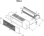
- FIG. 2 is an exploded perspective view illustrating some components of the air conditioner according to the embodiment of the present invention
- FIG. 3 is an exploded perspective view illustrating some other components of the air conditioner according to the embodiment of the present invention
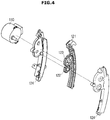
- FIG. 4 is an exploded perspective view illustrating a gear assembly of the air conditioner according to the embodiment of the present invention
- FIG. 5 is a cross-sectional view illustrating the air conditioner according to the embodiment of the present invention.
- the air conditioner 1 includes a housing 10 having an air inlet 14 and an air outlet 13, a heat exchanger 20 arranged inside the housing 10 and heat-exchanging with air introduced to the inside of the housing 10, a fan 30 for suctioning air to the inside of the housing 10 and moving the suctioned air toward the air outlet 13, and a door 100 for opening and closing the air outlet 13.
- the housing 10 may be provided in a rectangular parallelepiped shape having a transverse length longer than a longitudinal length, and the air outlet 13 may also be formed in a rectangular shape corresponding to the length of the housing 10.
- the door 100 may also be formed in a rectangular shape to correspond to the air outlet 13.
- the air outlet 13 may be arranged on a front surface of the housing 10, and the door 100 may be arranged in front of the housing 10 to open and close the air outlet 13.
- the door 100 is configured to selectively open a first portion of the fan 13 and a second portion of the fan 13 that is different from the first portion.
- the door 100 may be arranged on the housing 10 to be movable in a first direction and a second direction.
- the first portion of the air outlet 13 is opened when the door 100 is moved in the first direction
- the second portion of the air outlet 13 is opened when the door 100 is moved in the first direction.
- the door 100 may be arranged on the housing 10 to be movable upward and downward.
- the door may be configured to open a lower portion of the air outlet 13 by moving upward, and open an upper portion of the air outlet 13 by moving downward.
- the door 100 includes a plurality of holes 101 for discharging air inside the housing 10 when the door 100 closes the air outlet 13, that is, when the door 100 closes both of the first portion and the second portion of the air outlet 13.
- the plurality of holes 101 may be provided as a circular hole, and may be formed in various shapes, such as a triangle, a square, a star, and the like.
- the plurality of holes for discharging air inside the housing 10 when the air outlet 13 is closed by the door 100 may also be formed in at least a part of a lateral surface and/or a lower surface of the housing 10.
- the air conditioner 1 may control an airflow, such as a wind direction and wind volume of the discharged air, by selectively opening and closing the first portion or the second portion of the air outlet 13 using the door 100.
- an airflow such as a wind direction and wind volume of the discharged air
- the air conditioner 1 may be provided to be installed on a wall surface.
- the housing 10 may include a chassis 12 on which various components arranged inside the housing 10, such as the heat exchanger 20 and the fan 30, may be mounted and a cover 11 surrounding the chassis 12.
- the cover 11 may be provided at an upper surface thereof with an air inlet 14 through which air is suctioned into the interior space of the housing 10.
- An opening may be formed in a rear surface of the cover 11 and a rear surface of the chassis 12 to suction air to the interior space of the housing 10.
- the cover 11 may be provided at a front surface thereof with the air outlet 13 through which air from the fan 30 is blown to the outside of the housing 10.
- the air outlet 13 may have a cross-section whose area gradually increases toward the outside of the housing 10. That is, the cover 11 may include a first inclined wall 15 forming an upper surface of the air outlet 13 and a second inclined wall 16 forming a lower surface of the air outlet 13.
- a control panel (not shown) may be coupled to one surface of the cover 11.
- the control panel may include a receiver for receiving a signal from a remote controller and a display for displaying the operation state of the air conditioner 1.
- the control panel may be provided at an inside thereof with a printed circuit board for operating the receiver or the display.
- the heat exchanger 20 is arranged inside the housing 10 and configured to heat-exchange with air introduced into the air inlet 14. That is, the heat exchanger 20 is configured to absorb heat from air introduced through the air inlet 14 or transfer heat to air introduced through the air inlet 14.
- the air inlet 14 may be formed in a rectangular shape to correspond to the length of the housing 10, and the heat exchanger 20 may have a length corresponding to a length of the air inlet 14.
- the heat exchanger 20 may be arranged to surround a part of the fan 30 between the air inlet 14 and the fan 30. Although not shown in the drawings, the heat exchanger may be arranged between the fan and the air outlet.
- a filter (not shown) may be attached to the air inlet 14 of the housing 10.
- the filter may filter out foreign substance, such as dust, contained in the outside air suctioned through the air inlet 14.
- the air conditioner 1 may further include an additional filter provided inside the housing 10 to filter out and remove foreign substance, such as dust, odor particles, and the like, contained in the air.
- the fan 30 may be implemented using a cross flow fan having a shape and length corresponding to those of the housing 10. That is, the fan 30 may be arranged with a rotating shaft thereof in parallel to the air inlet 14 and the air outlet 13.
- the fan 30 may be rotatably mounted on the chassis 12, and may be rotated by a fan motor 31 mounted on the chassis 12.
- the chassis 13 may be provided with an operating portion 18 that includes a circuit board and the like configured to operate the fan motor 31 for driving the fan 30 and operate other components of the air conditioner 1.
- the first inclined wall 15, arranged at the front side of the cover 11, may be provided at a rear surface thereof with a water trap 21 to collect water condensed in the heat exchanger 20, and include a drain pipe (not shown) for draining the water collected in the water trap 21.
- the housing 10 may include a guide surface 19 having a curved surface that surrounds part of the fan 30 to form a flow path of air from the fan 30.
- the guide surface 19 may be provided on the chassis 12 and arranged at a rear side of the fan 30.
- a guide member 200 for determining a blowing direction of the fan 30 is mounted on the chassis 12.
- the guide member 200 is referred to as a stabilizer.
- the guide member 200 may be formed to surround part of the fan 30 at a predetermined interval from the fan 30 to divide a suctioned air flow path and a discharged air flow path of the fan 30, and may be formed to determine the position and intensity of a vortex of the discharged air.
- the guide member 200 and the guide surface 19 may form the discharged air flow path of the fan 30.
- the guide member 200 is configured to be rotatable along a circumferential direction of the fan 30 to change the flow path of air discharged from the fan 30. That is, the guide member 200 is arranged in the housing 10 to be rotatable on the same center of rotation as that of the fan 30.
- the guide member 200 is configured to be movable between a first position in which air from the fan 30 is guided to the first portion of the air outlet 13 and a second position in which air from the fan 30 is guided to the second portion of the air outlet 30.
- the chassis 12 may have a first motor 210 for driving the guide member 200.
- the guide member 200 is provided at one side thereof with a first motor connector 201 and at the other side thereof with a fan motor connector 202.
- the first motor connector 201 of the guide member 200 is connected to a driving shaft of the first motor 210 mounted on the chassis 12, and the fan motor connector 202 of the guide member 200 is connected to a driving shaft of the fan motor 31 mounted on the chassis 12.
- the first motor 210 and the fan motor 31 may be arranged to face each other with the guide member 200 and the fan 30 interposed therebetween.
- the first motor 210 may be arranged with a driving axis line aligned with that of the fan motor 31, and configured to rotate the guide member 200.
- the guide member 200 may include a bearing 203 provided on the fan motor connector 202 not to be rotated by the fan motor 31.
- a guide blade may be provided to be rotatable by a manual operation of a user.
- the guide blade may include a handle that may be manually rotated.
- the door 100 may include a curved surface 102.
- the door 100 may include a curved surface 102 bulging toward the housing 10.
- the curved surface 102 of the door 100 may be configured to guide air from the fan 30 to the first portion or the second portion of the air outlet 13.
- the door 100 may be arranged in the housing 10 to be movable along a curved line having the same center of curvature as that of the center of curvature of the curved surface 102.
- the door 100 while moving along an extension of the curved surface 102, moves in a first direction to open the first portion of the air outlet 13 or moves in a second direction to open the second portion of the air outlet 13, to guide air from the fan 30 to the first portion of the air outlet 13 or to the second portion of the air outlet 13.
- the air conditioner 1 may include a second motor 110 for driving the door 100 and a gear assembly 120 for connecting the second motor 110 to the door 100.
- the second motor 110 and the gear assembly 120 may be arranged on an inner surface of the housing 10, that is, on an inner surface of the cover 11.
- the cover 11 may be provided with a slit 17 for connection between the gear assembly 120 and the door 100.
- the door 100 has one side thereof connected to the gear assembly 120 and the second motor 110, and the other side thereof having a rail (103 in FIG. 6 ) for guiding movement of the door 100.
- the second motor 110 and the gear assembly 120 may be arranged on each lateral side surface of the housing 10.
- the gear assembly 120 includes a gear housing 124, a first gear 121 coupled to the door 100, a second gear 122 coupled to the second motor 110, and a third gear 123 connecting the first gear 121 to the second gear 122.
- the first gear 121 may be provided as a rack, and the third gear 123 may be provided as a pinion.
- the first gear 121 may include a curved linehaving the same curvature as that of the curved surface 102 of the door 100 such that the door 100 moves along the extension of the curved surface 102.
- the air conditioner 1 may variously set and control the airflow, such as a wind direction or wind volume, through the door 100 and the guide member 200.
- FIG. 6 is a cross-sectional view illustrating a downward wind mode of the air conditioner according to the embodiment of the present invention.
- FIG. 7 is a cross-sectional view illustrating an upward wind mode of the air conditioner according to the embodiment of the present invention
- FIG. 8 is a cross-sectional view illustrating a still-air mode of the air conditioner according to the embodiment of the present invention.
- the door 100 moves in a first direction A to open a first portion 13a of the air outlet 13 with a second portion 13b of the air outlet 13 closed.
- the door 100 opens a lower portion 13a of the air outlet 13 with an upper portion 13b of the air outlet 13 closed, by moving in the first direction A.
- the air conditioner 1 When the air conditioner 1 is operated with the lower portion 13a of the air outlet 13 opened, wind is discharged with an airflow having a higher wind speed and a wind direction oriented in the front and rear side directions.
- the air conditioner 1 may be installed on a wall surface, and under the assumption that the air conditioner 1 is installed on an upper portion of a wall surface, an operating mode in which the air conditioner 1 operates with the lower portion 13a of the air outlet 13 opened may be defined as a downward wind mode or a direct wind mode.
- the direct wind mode provides a user with an instantaneous cooling or heating, and allows the interior to be rapidly air conditioned with a high wind speed and a great wind volume.
- the guide member 200 may be located in a first position 200a in which air from the fan 30 is guided to a first flow path directed toward the first portion 13a of the air outlet 13. That is, when the door 100 is moved upward to open the first portion 13a of the air outlet 13, the guide member 200 may be moved to the first position 200a.
- the guide member 200 in the first position 200a may guide air from the fan 30 in a radial direction of the fan 30. That is, the guide member 200 in the first position 200a may guide air from the fan 300 to be moved along a tangent line of the fan 30 together with the second inclined wall 16 of the cover 11.
- the door 100 may partly open the first portion 13a of the air outlet 13. That is, the air conditioner 1 may control an opening area of the upper portion 13b of the air outlet 13 by adjusting the displacement of the door 100.
- the door 100 may move in a second direction B to open the second portion 13b of the air outlet 13 with the first portion 13a of the air outlet 13 closed.
- the door 100 may open an upper portion 13b of the air outlet 13 with a lower portion 13a of the air outlet 13 closed, by moving downward.
- the air conditioner 1 may be installed on a wall surface, and under the assumption that the air conditioner 1 is installed on an upper portion of a wall surface, an operating mode in which the air conditioner 1 operates with the second air outlet 210 opened may be defined as an upward wind mode or an indirect wind mode.
- the indirect wind mode prevents wind from being directly delivered to a user, allows the interior to be cooled by convection, and allows the interior to be rapidly air conditioned with a high wind speed and a great wind volume.
- the guide member 200 may be located in a second position 200b in which air from the fan 30 is guided to a second flow path directed toward the second portion 13b of the air outlet 13. That is, when the door 100 is moved upward to open the second portion 13b of the air outlet 13, the guide member 200 may be moved to the second position 200b.
- the guide member 200 in the second position 200b may guide air from the fan 30 in a circumferential direction of the fan 30. That is, the guide member 200 in the second position 200b may guide air from the fan 300 to be moved along a periphery of the fan 30 together with the curved surface 102 of the door 100.
- the door 100 may partly open the second portion 13b of the air outlet 13. That is, the air conditioner 1 may control an opening area of the lower portion 13a of the air outlet 13 by adjusting the displacement of the door 100.
- the air conditioner 1 may visualize the direction of discharged airflow through the up and down movement of the door 100 so that users may be intuitively identified of the wind direction.
- the user may be intuitively identified of the airflow information, such as wind volume or wind speed, from the up and down movement displacement of the door 100.
- the guide member 200 may be moved to the second position 200b in a state in which the air outlet 13 is closed by the door 100.
- a plurality of holes 101 may be uniformly distributed on the door 100.
- An operating mode in which the air conditioner 1 operates with the air outlet 13 closed is defined as a still-air mode.
- the still-air mode allows the interior to be slowly air-conditioned as a whole while preventing wind from being directly delivered to a user.
- the lower portion 13a of the air outlet 13 is opened, so that air from the fan 30 forms a strong airflow toward the lower portion 13a of the air outlet 13. Accordingly, the amount of air from the fan 30 discharged through the plurality of holes 101 in the door 100 is zero or extremely small.
- the upper portion 13b of the air outlet 13 is opened, so that air from the fan 30 forms a strong airflow toward the upper portion 13b of the air outlet 13. Accordingly, the amount of air from the fan 30 discharged through the plurality of holes 101 in the door 100 is zero or extremely small.
- the air outlet does not have any portion thereof open, so that air from the fan 30 may be discharged to the outside of the housing 10 through the plurality of holes 101 formed in the door 100 at a low speed as a whole.
- the plurality of holes for the still-air mode operation may be formed not only in the door 100 but also in the housing 10.
- the plurality of holes 101 may have the same diameter, and in this case, the aesthetics may be improved since the plurality of holes seen in the external appearance all have the same diameter.
- the plurality of holes 101 may have different diameters.
- a hole arranged at a portion in which air from the fan 30 has a higher flow rate is formed to have a smaller diameter
- a hole arranged at a portion in which air from the fan 30 has a lower airflow is formed to have a larger diameter.
- the air conditioner 1 may allow air to be discharged at the same flow rate through all the holes.
Landscapes
- Engineering & Computer Science (AREA)
- Chemical & Material Sciences (AREA)
- Combustion & Propulsion (AREA)
- Mechanical Engineering (AREA)
- General Engineering & Computer Science (AREA)
- Air-Flow Control Members (AREA)
- Air-Conditioning Room Units, And Self-Contained Units In General (AREA)
Applications Claiming Priority (2)
| Application Number | Priority Date | Filing Date | Title |
|---|---|---|---|
| KR1020160137920A KR102629978B1 (ko) | 2016-10-21 | 2016-10-21 | 공기조화기 |
| PCT/KR2017/008087 WO2018074712A1 (ko) | 2016-10-21 | 2017-07-27 | 공기조화기 |
Publications (3)
| Publication Number | Publication Date |
|---|---|
| EP3514459A1 EP3514459A1 (en) | 2019-07-24 |
| EP3514459A4 EP3514459A4 (en) | 2019-09-25 |
| EP3514459B1 true EP3514459B1 (en) | 2021-11-03 |
Family
ID=62018808
Family Applications (1)
| Application Number | Title | Priority Date | Filing Date |
|---|---|---|---|
| EP17862937.4A Active EP3514459B1 (en) | 2016-10-21 | 2017-07-27 | Air conditioner |
Country Status (5)
| Country | Link |
|---|---|
| US (1) | US11137148B2 (ko) |
| EP (1) | EP3514459B1 (ko) |
| KR (1) | KR102629978B1 (ko) |
| CN (1) | CN109891161B (ko) |
| WO (1) | WO2018074712A1 (ko) |
Families Citing this family (7)
| Publication number | Priority date | Publication date | Assignee | Title |
|---|---|---|---|---|
| US10865798B2 (en) * | 2016-05-30 | 2020-12-15 | Zhongshan Broad-Ocean Motor Co., Ltd. | Fan coil unit |
| US10895398B2 (en) * | 2017-03-01 | 2021-01-19 | Ice Qube, Inc. | Recessed-mounted air conditioning unit |
| CN110925879A (zh) * | 2018-09-04 | 2020-03-27 | 青岛海尔空调器有限总公司 | 一种空调内机导风装置 |
| KR102575515B1 (ko) * | 2018-12-19 | 2023-09-05 | 엘지디스플레이 주식회사 | 디스플레이 장치 |
| KR102232946B1 (ko) * | 2020-12-28 | 2021-03-26 | 김선태 | 자외선살균기능 쿨러가 장착된 저장용 냉동·냉장 창고 |
| CN113701335B (zh) * | 2021-08-31 | 2022-10-28 | 青岛海尔空调器有限总公司 | 壁挂式空调室内机 |
| CN113701334B (zh) * | 2021-08-31 | 2022-10-28 | 青岛海尔空调器有限总公司 | 壁挂式空调室内机 |
Family Cites Families (19)
| Publication number | Priority date | Publication date | Assignee | Title |
|---|---|---|---|---|
| JPS63147652A (ja) | 1986-12-10 | 1988-06-20 | Nec Corp | インクジエツト記録装置 |
| JPS63147652U (ko) * | 1987-03-17 | 1988-09-29 | ||
| EP1188993A4 (en) | 2000-04-19 | 2004-03-31 | Daikin Ind Ltd | AIR CONDITIONER |
| KR100554285B1 (ko) * | 2004-01-14 | 2006-02-24 | 삼성전자주식회사 | 공기조화기의 흡입구 개폐장치 |
| JP4880345B2 (ja) * | 2006-04-13 | 2012-02-22 | シャープ株式会社 | 空気調和機 |
| JP2008128622A (ja) * | 2006-11-24 | 2008-06-05 | Sharp Corp | 空気調和機 |
| JP2008151477A (ja) * | 2006-12-20 | 2008-07-03 | Daikin Ind Ltd | 床置型空気調和機 |
| KR101339940B1 (ko) * | 2007-05-18 | 2013-12-10 | 엘지전자 주식회사 | 공기조화기 및 그 제어 방법 |
| CN101581472A (zh) * | 2008-05-13 | 2009-11-18 | 乐金电子(天津)电器有限公司 | 空调器 |
| US9180751B2 (en) * | 2011-08-18 | 2015-11-10 | Halla Visteon Climate Control Corporation | Air conditioner for vehicle |
| KR20140018445A (ko) * | 2012-07-06 | 2014-02-13 | 삼성전자주식회사 | 공기조화기의 실내기 |
| KR102055939B1 (ko) * | 2012-10-10 | 2019-12-13 | 엘지전자 주식회사 | 공기 조화기 |
| EP2719958A3 (en) * | 2012-10-10 | 2017-11-01 | LG Electronics, Inc. | Air conditioner |
| CN103322661B (zh) * | 2013-06-20 | 2016-11-02 | 广东美的制冷设备有限公司 | 出风口导风结构、空调器及空调器的控制方法 |
| KR102152645B1 (ko) * | 2013-09-17 | 2020-09-08 | 삼성전자주식회사 | 공기조화기 |
| CN104697053B (zh) * | 2015-02-13 | 2018-03-09 | 广东美的制冷设备有限公司 | 空调器室内机和挡风板 |
| CN104697060B (zh) * | 2015-02-13 | 2018-03-30 | 广东美的制冷设备有限公司 | 空调室内机及其控制方法 |
| KR101718206B1 (ko) * | 2015-04-09 | 2017-03-22 | 한국과학기술원 | 로드 분산을 위한 동적 스펙트럼 할당 방식 |
| CN204901976U (zh) * | 2015-08-07 | 2015-12-23 | 广东美的制冷设备有限公司 | 空调室内机及空调器 |
-
2016
- 2016-10-21 KR KR1020160137920A patent/KR102629978B1/ko active IP Right Grant
-
2017
- 2017-07-27 CN CN201780064762.XA patent/CN109891161B/zh active Active
- 2017-07-27 EP EP17862937.4A patent/EP3514459B1/en active Active
- 2017-07-27 US US16/343,620 patent/US11137148B2/en active Active
- 2017-07-27 WO PCT/KR2017/008087 patent/WO2018074712A1/ko unknown
Also Published As
| Publication number | Publication date |
|---|---|
| EP3514459A4 (en) | 2019-09-25 |
| EP3514459A1 (en) | 2019-07-24 |
| KR20180044160A (ko) | 2018-05-02 |
| KR102629978B1 (ko) | 2024-01-29 |
| WO2018074712A1 (ko) | 2018-04-26 |
| US20190331350A1 (en) | 2019-10-31 |
| US11137148B2 (en) | 2021-10-05 |
| CN109891161B (zh) | 2021-06-15 |
| CN109891161A (zh) | 2019-06-14 |
Similar Documents
| Publication | Publication Date | Title |
|---|---|---|
| EP3514459B1 (en) | Air conditioner | |
| EP3396266B1 (en) | Air conditioner | |
| US11346576B2 (en) | Air conditioner | |
| CN108870536B (zh) | 空调 | |
| EP3183509B1 (en) | Air conditioner and control method thereof | |
| KR102569298B1 (ko) | 공기조화기 | |
| CN111615607B (zh) | 空调 | |
| CN109804202B (zh) | 空调 | |
| KR20190026325A (ko) | 공기조화기 | |
| US20220049854A1 (en) | Air conditioner | |
| EP3714213B1 (en) | Air conditioner | |
| KR102220818B1 (ko) | 공기조화기 | |
| KR20150027417A (ko) | 공기조화기 | |
| KR20150085219A (ko) | 공기조화기 |
Legal Events
| Date | Code | Title | Description |
|---|---|---|---|
| STAA | Information on the status of an ep patent application or granted ep patent |
Free format text: STATUS: THE INTERNATIONAL PUBLICATION HAS BEEN MADE |
|
| PUAI | Public reference made under article 153(3) epc to a published international application that has entered the european phase |
Free format text: ORIGINAL CODE: 0009012 |
|
| STAA | Information on the status of an ep patent application or granted ep patent |
Free format text: STATUS: REQUEST FOR EXAMINATION WAS MADE |
|
| 17P | Request for examination filed |
Effective date: 20190418 |
|
| AK | Designated contracting states |
Kind code of ref document: A1 Designated state(s): AL AT BE BG CH CY CZ DE DK EE ES FI FR GB GR HR HU IE IS IT LI LT LU LV MC MK MT NL NO PL PT RO RS SE SI SK SM TR |
|
| AX | Request for extension of the european patent |
Extension state: BA ME |
|
| A4 | Supplementary search report drawn up and despatched |
Effective date: 20190823 |
|
| RIC1 | Information provided on ipc code assigned before grant |
Ipc: F24F 1/00 20190101ALI20190819BHEP Ipc: F24F 13/12 20060101AFI20190819BHEP Ipc: F24F 1/0011 20190101ALI20190819BHEP Ipc: F24F 3/16 20060101ALI20190819BHEP Ipc: F24F 13/20 20060101ALI20190819BHEP |
|
| DAV | Request for validation of the european patent (deleted) | ||
| DAX | Request for extension of the european patent (deleted) | ||
| GRAP | Despatch of communication of intention to grant a patent |
Free format text: ORIGINAL CODE: EPIDOSNIGR1 |
|
| STAA | Information on the status of an ep patent application or granted ep patent |
Free format text: STATUS: GRANT OF PATENT IS INTENDED |
|
| RIC1 | Information provided on ipc code assigned before grant |
Ipc: F24F 1/0011 20190101ALI20210423BHEP Ipc: F24F 3/16 20210101ALI20210423BHEP Ipc: F24F 1/00 20190101ALI20210423BHEP Ipc: F24F 13/20 20060101ALI20210423BHEP Ipc: F24F 13/12 20060101AFI20210423BHEP |
|
| INTG | Intention to grant announced |
Effective date: 20210528 |
|
| GRAS | Grant fee paid |
Free format text: ORIGINAL CODE: EPIDOSNIGR3 |
|
| GRAA | (expected) grant |
Free format text: ORIGINAL CODE: 0009210 |
|
| STAA | Information on the status of an ep patent application or granted ep patent |
Free format text: STATUS: THE PATENT HAS BEEN GRANTED |
|
| AK | Designated contracting states |
Kind code of ref document: B1 Designated state(s): AL AT BE BG CH CY CZ DE DK EE ES FI FR GB GR HR HU IE IS IT LI LT LU LV MC MK MT NL NO PL PT RO RS SE SI SK SM TR |
|
| REG | Reference to a national code |
Ref country code: GB Ref legal event code: FG4D |
|
| REG | Reference to a national code |
Ref country code: AT Ref legal event code: REF Ref document number: 1444291 Country of ref document: AT Kind code of ref document: T Effective date: 20211115 Ref country code: CH Ref legal event code: EP |
|
| REG | Reference to a national code |
Ref country code: IE Ref legal event code: FG4D |
|
| REG | Reference to a national code |
Ref country code: DE Ref legal event code: R096 Ref document number: 602017048886 Country of ref document: DE |
|
| REG | Reference to a national code |
Ref country code: LT Ref legal event code: MG9D |
|
| REG | Reference to a national code |
Ref country code: NL Ref legal event code: MP Effective date: 20211103 |
|
| REG | Reference to a national code |
Ref country code: AT Ref legal event code: MK05 Ref document number: 1444291 Country of ref document: AT Kind code of ref document: T Effective date: 20211103 |
|
| PG25 | Lapsed in a contracting state [announced via postgrant information from national office to epo] |
Ref country code: RS Free format text: LAPSE BECAUSE OF FAILURE TO SUBMIT A TRANSLATION OF THE DESCRIPTION OR TO PAY THE FEE WITHIN THE PRESCRIBED TIME-LIMIT Effective date: 20211103 Ref country code: LT Free format text: LAPSE BECAUSE OF FAILURE TO SUBMIT A TRANSLATION OF THE DESCRIPTION OR TO PAY THE FEE WITHIN THE PRESCRIBED TIME-LIMIT Effective date: 20211103 Ref country code: FI Free format text: LAPSE BECAUSE OF FAILURE TO SUBMIT A TRANSLATION OF THE DESCRIPTION OR TO PAY THE FEE WITHIN THE PRESCRIBED TIME-LIMIT Effective date: 20211103 Ref country code: BG Free format text: LAPSE BECAUSE OF FAILURE TO SUBMIT A TRANSLATION OF THE DESCRIPTION OR TO PAY THE FEE WITHIN THE PRESCRIBED TIME-LIMIT Effective date: 20220203 Ref country code: AT Free format text: LAPSE BECAUSE OF FAILURE TO SUBMIT A TRANSLATION OF THE DESCRIPTION OR TO PAY THE FEE WITHIN THE PRESCRIBED TIME-LIMIT Effective date: 20211103 |
|
| PG25 | Lapsed in a contracting state [announced via postgrant information from national office to epo] |
Ref country code: IS Free format text: LAPSE BECAUSE OF FAILURE TO SUBMIT A TRANSLATION OF THE DESCRIPTION OR TO PAY THE FEE WITHIN THE PRESCRIBED TIME-LIMIT Effective date: 20220303 Ref country code: SE Free format text: LAPSE BECAUSE OF FAILURE TO SUBMIT A TRANSLATION OF THE DESCRIPTION OR TO PAY THE FEE WITHIN THE PRESCRIBED TIME-LIMIT Effective date: 20211103 Ref country code: PT Free format text: LAPSE BECAUSE OF FAILURE TO SUBMIT A TRANSLATION OF THE DESCRIPTION OR TO PAY THE FEE WITHIN THE PRESCRIBED TIME-LIMIT Effective date: 20220303 Ref country code: PL Free format text: LAPSE BECAUSE OF FAILURE TO SUBMIT A TRANSLATION OF THE DESCRIPTION OR TO PAY THE FEE WITHIN THE PRESCRIBED TIME-LIMIT Effective date: 20211103 Ref country code: NO Free format text: LAPSE BECAUSE OF FAILURE TO SUBMIT A TRANSLATION OF THE DESCRIPTION OR TO PAY THE FEE WITHIN THE PRESCRIBED TIME-LIMIT Effective date: 20220203 Ref country code: NL Free format text: LAPSE BECAUSE OF FAILURE TO SUBMIT A TRANSLATION OF THE DESCRIPTION OR TO PAY THE FEE WITHIN THE PRESCRIBED TIME-LIMIT Effective date: 20211103 Ref country code: LV Free format text: LAPSE BECAUSE OF FAILURE TO SUBMIT A TRANSLATION OF THE DESCRIPTION OR TO PAY THE FEE WITHIN THE PRESCRIBED TIME-LIMIT Effective date: 20211103 Ref country code: HR Free format text: LAPSE BECAUSE OF FAILURE TO SUBMIT A TRANSLATION OF THE DESCRIPTION OR TO PAY THE FEE WITHIN THE PRESCRIBED TIME-LIMIT Effective date: 20211103 Ref country code: GR Free format text: LAPSE BECAUSE OF FAILURE TO SUBMIT A TRANSLATION OF THE DESCRIPTION OR TO PAY THE FEE WITHIN THE PRESCRIBED TIME-LIMIT Effective date: 20220204 Ref country code: ES Free format text: LAPSE BECAUSE OF FAILURE TO SUBMIT A TRANSLATION OF THE DESCRIPTION OR TO PAY THE FEE WITHIN THE PRESCRIBED TIME-LIMIT Effective date: 20211103 |
|
| PG25 | Lapsed in a contracting state [announced via postgrant information from national office to epo] |
Ref country code: SM Free format text: LAPSE BECAUSE OF FAILURE TO SUBMIT A TRANSLATION OF THE DESCRIPTION OR TO PAY THE FEE WITHIN THE PRESCRIBED TIME-LIMIT Effective date: 20211103 Ref country code: SK Free format text: LAPSE BECAUSE OF FAILURE TO SUBMIT A TRANSLATION OF THE DESCRIPTION OR TO PAY THE FEE WITHIN THE PRESCRIBED TIME-LIMIT Effective date: 20211103 Ref country code: RO Free format text: LAPSE BECAUSE OF FAILURE TO SUBMIT A TRANSLATION OF THE DESCRIPTION OR TO PAY THE FEE WITHIN THE PRESCRIBED TIME-LIMIT Effective date: 20211103 Ref country code: EE Free format text: LAPSE BECAUSE OF FAILURE TO SUBMIT A TRANSLATION OF THE DESCRIPTION OR TO PAY THE FEE WITHIN THE PRESCRIBED TIME-LIMIT Effective date: 20211103 Ref country code: DK Free format text: LAPSE BECAUSE OF FAILURE TO SUBMIT A TRANSLATION OF THE DESCRIPTION OR TO PAY THE FEE WITHIN THE PRESCRIBED TIME-LIMIT Effective date: 20211103 Ref country code: CZ Free format text: LAPSE BECAUSE OF FAILURE TO SUBMIT A TRANSLATION OF THE DESCRIPTION OR TO PAY THE FEE WITHIN THE PRESCRIBED TIME-LIMIT Effective date: 20211103 |
|
| PGFP | Annual fee paid to national office [announced via postgrant information from national office to epo] |
Ref country code: GB Payment date: 20220620 Year of fee payment: 6 |
|
| REG | Reference to a national code |
Ref country code: DE Ref legal event code: R097 Ref document number: 602017048886 Country of ref document: DE |
|
| PLBE | No opposition filed within time limit |
Free format text: ORIGINAL CODE: 0009261 |
|
| STAA | Information on the status of an ep patent application or granted ep patent |
Free format text: STATUS: NO OPPOSITION FILED WITHIN TIME LIMIT |
|
| 26N | No opposition filed |
Effective date: 20220804 |
|
| PG25 | Lapsed in a contracting state [announced via postgrant information from national office to epo] |
Ref country code: AL Free format text: LAPSE BECAUSE OF FAILURE TO SUBMIT A TRANSLATION OF THE DESCRIPTION OR TO PAY THE FEE WITHIN THE PRESCRIBED TIME-LIMIT Effective date: 20211103 |
|
| PG25 | Lapsed in a contracting state [announced via postgrant information from national office to epo] |
Ref country code: SI Free format text: LAPSE BECAUSE OF FAILURE TO SUBMIT A TRANSLATION OF THE DESCRIPTION OR TO PAY THE FEE WITHIN THE PRESCRIBED TIME-LIMIT Effective date: 20211103 |
|
| PG25 | Lapsed in a contracting state [announced via postgrant information from national office to epo] |
Ref country code: MC Free format text: LAPSE BECAUSE OF FAILURE TO SUBMIT A TRANSLATION OF THE DESCRIPTION OR TO PAY THE FEE WITHIN THE PRESCRIBED TIME-LIMIT Effective date: 20211103 |
|
| REG | Reference to a national code |
Ref country code: CH Ref legal event code: PL |
|
| REG | Reference to a national code |
Ref country code: BE Ref legal event code: MM Effective date: 20220731 |
|
| PG25 | Lapsed in a contracting state [announced via postgrant information from national office to epo] |
Ref country code: LU Free format text: LAPSE BECAUSE OF NON-PAYMENT OF DUE FEES Effective date: 20220727 Ref country code: LI Free format text: LAPSE BECAUSE OF NON-PAYMENT OF DUE FEES Effective date: 20220731 Ref country code: FR Free format text: LAPSE BECAUSE OF NON-PAYMENT OF DUE FEES Effective date: 20220731 Ref country code: CH Free format text: LAPSE BECAUSE OF NON-PAYMENT OF DUE FEES Effective date: 20220731 |
|
| PG25 | Lapsed in a contracting state [announced via postgrant information from national office to epo] |
Ref country code: IT Free format text: LAPSE BECAUSE OF FAILURE TO SUBMIT A TRANSLATION OF THE DESCRIPTION OR TO PAY THE FEE WITHIN THE PRESCRIBED TIME-LIMIT Effective date: 20211103 Ref country code: BE Free format text: LAPSE BECAUSE OF NON-PAYMENT OF DUE FEES Effective date: 20220731 |
|
| PG25 | Lapsed in a contracting state [announced via postgrant information from national office to epo] |
Ref country code: IE Free format text: LAPSE BECAUSE OF NON-PAYMENT OF DUE FEES Effective date: 20220727 |
|
| PGFP | Annual fee paid to national office [announced via postgrant information from national office to epo] |
Ref country code: DE Payment date: 20230620 Year of fee payment: 7 |
|
| GBPC | Gb: european patent ceased through non-payment of renewal fee |
Effective date: 20230727 |
|
| PG25 | Lapsed in a contracting state [announced via postgrant information from national office to epo] |
Ref country code: HU Free format text: LAPSE BECAUSE OF FAILURE TO SUBMIT A TRANSLATION OF THE DESCRIPTION OR TO PAY THE FEE WITHIN THE PRESCRIBED TIME-LIMIT; INVALID AB INITIO Effective date: 20170727 |
|
| PG25 | Lapsed in a contracting state [announced via postgrant information from national office to epo] |
Ref country code: MK Free format text: LAPSE BECAUSE OF FAILURE TO SUBMIT A TRANSLATION OF THE DESCRIPTION OR TO PAY THE FEE WITHIN THE PRESCRIBED TIME-LIMIT Effective date: 20211103 Ref country code: CY Free format text: LAPSE BECAUSE OF FAILURE TO SUBMIT A TRANSLATION OF THE DESCRIPTION OR TO PAY THE FEE WITHIN THE PRESCRIBED TIME-LIMIT Effective date: 20211103 Ref country code: GB Free format text: LAPSE BECAUSE OF NON-PAYMENT OF DUE FEES Effective date: 20230727 |